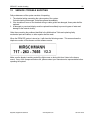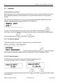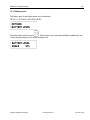
1
PRS40 EZ INSTALLATION, CALIBRATION and SERVICE MANUAL SkyAzúl, Equipment Solutions 6126 www.skyazul.com 301-371- NOTICE SkyAzúl makes no warranty of any kind with regard to this material, including, but not limited to, the implied warranties of merchantability and/or its fitness for a particular purpose. SkyAzúl will not be liable for errors contained in this manual or for incidental or consequential damages in connection with the furnishing, performance, or use of this manual. This document contains proprietary information, which is protected by copyright, and all rights are reserved. No part of this document may be photocopied, reproduced, or translated to another language without the prior written consent of SkyAzúl. SkyAzúl reserves proprietary rights to all drawings, photos and the data contained therein. The drawings, photos and data are confidential and cannot be used or reproduced without the written consent of SkyAzúl. The drawings and/or photos are subject to technical modification without prior notice. All information in this document is subject to change without notice. SkyAzúl, Inc. 200 W. Main Street, Suite, 2A Middletown, MD 21769 Fax 301-371-0029 [email protected] SkyAzúl, Equipment Solutions www.skyazul.com 301-371-6126 SkyAzúl, Equipment Solutions www.skyazul.com 301-371-6126 5 TABLE OF CONTENTS 1 GENERAL INFORMATION..............................................................................................................1 2 WARNINGS .....................................................................................................................................1 3 FEATURES ......................................................................................................................................2 4 SYSTEM DESCRIPTION.................................................................................................................2 4.1 CONSOLE .......................................................................................................................................2 4.1.1 4.1.2 Liquid Crystal Display ...........................................................................................................................2 Control Identification .............................................................................................................................3 4.2 OPERATION ....................................................................................................................................4 4.2.1 4.2.2 5 MENU STRUCTURE ............................................................................................................................5 Installation.............................................................................................................................................6 ANGLE .............................................................................................................................................7 5.1.1 5.1.2 5.1.3 5.1.4 Operation ..............................................................................................................................................7 Limits.....................................................................................................................................................7 Installation / Calibration Hardwired.......................................................................................................8 Calibration.............................................................................................................................................9 5.2 ANGLE .........................................................................................................................................10 6 A2B ................................................................................................................................................12 6.1.1 6.1.2 6.1.3 6.1.4 7 WIND..............................................................................................................................................19 7.1.1 7.1.2 7.1.3 7.1.4 8 Operation ............................................................................................................................................19 LIMITS ................................................................................................................................................20 Installation...........................................................................................................................................20 Wind Setup .........................................................................................................................................21 LOADCELL ....................................................................................................................................23 8.1.1 8.1.2 8.1.3 8.1.4 8.1.5 9 Operation ............................................................................................................................................12 A2B limit..............................................................................................................................................15 Installation...........................................................................................................................................15 A2B Setup...........................................................................................................................................17 Operation ............................................................................................................................................23 LIMITS ................................................................................................................................................24 Installation...........................................................................................................................................25 Loadcell Setup ....................................................................................................................................26 Loadcell Calibration ............................................................................................................................26 LINE RIDER ...................................................................................................................................28 9.1.1 9.1.2 9.1.3 9.1.4 9.1.5 Operation ............................................................................................................................................28 LIMITS ................................................................................................................................................29 Installation...........................................................................................................................................29 Linerider setup ....................................................................................................................................33 Linerider Calibration............................................................................................................................33 10 RADIO MODULE ...........................................................................................................................34 10.1 INSTALLATION...............................................................................................................................34 11 ADDING SENSORS.......................................................................................................................36 12 SERVICE / TROUBLE SHOOTING ...............................................................................................37 12.1 SCREENS .....................................................................................................................................38 12.1.1 To test the outputs: .............................................................................................................................38 12.1.2 To test the inputs: ...............................................................................................................................38 12.1.3 Battery level: .......................................................................................................................................39 12.2 TROUBLESHOOTING ......................................................................................................................40 12.3 TROUBLESHOOTING MOISTURE .....................................................................................................41 12.3.1 Water Ingress .....................................................................................................................................41 13 MAINTENANCE .............................................................................................................................42 SkyAzúl, Equipment Solutions www.skyazul.com 301-371-6126 6 Operator’s / Service Manual, PRS 40 EZ 13.1 BATTERY REPLACEMENT ........................................................................................................... 42 14 PART NUMBERS...........................................................................................................................43 14.1 CONSOLE ..................................................................................................................................43 14.2 A2B .............................................................................................................................................44 14.3 WIND .........................................................................................................................................46 14.4 ANGLE ..........................................................................................................................................47 14.5 ANTENNA OPTIONS .......................................................................................................................48 14.6 LINERIDER ....................................................................................................................................49 14.7 LOADCELL .................................................................................................................................50 SkyAzúl, Equipment Solutions www.skyazul.com 301-371-6126 General Information 1 1 GENERAL INFORMATION The PRS 40 EZ System has been designed to provide indication from various types of sensors, i.e. A2B, Load, Wind and Angle. The A2B system will warn the crane operator of a two-blocking condition of the crane. If a two-blocking condition is approached, the system will warn the operator by sounding an audible alarm, flashing the backlit LCD and locking out those functions which may aggravate the crane's condition, whenever applicable. If the system is set up for load, angle or wind, limits can be set by the user. When these limits are exceeded the system will warn the operator by sounding an audible alarm, flashing the backlit LCD and de-energize the lockout relay. The system relay can be connected to the cranes lockout system. If so, the system will lock out when exceeding any of the user limits. NOTE: The term "two-block" is a crane term that refers to a condition when the load handling device comes in contact with the boom head. This condition, if not prevented, may cause the wire rope to break, allowing the load to fall. Either raising the load into the boom head, or telescoping the boom out without paying attention to the hoist line can cause a "two- block" condition. 2 WARNINGS The PRS 40 EZ System is an operational aid, which warns a crane operator of approaching two-block conditions, which could cause damage to equipment and personal injury. This device is not, and must not be a substitute for good, sound operator judgment, experience and use of accepted safe crane operating procedures. The responsibility for the safe operation of the crane remains with the crane operator who must ensure that all warnings and instructions supplied are fully understood and observed. Prior to operating the crane, the operator must carefully and thoroughly read and understand the information in this manual to ensure that the operation and limitations of the system and the crane are known. The system can only work correctly, if all sensors/transmitters have been properly set. For correct setup, the operator has to answer thoroughly and correctly all questions asked during the setup procedure in accordance with the real rigging state of the crane. To prevent material damage and serious or even fatal accidents, the correct adjustment of the system has to be ensured before starting the crane operation. Always refer to operational instructions and load charts provided by the crane manufacturer for specific crane operation and load limits. SkyAzúl, Equipment Solutions www.skyazul.com 301-371-6126 2 Operator’s / Service Manual, PRS 40 EZ 3 FEATURES The PRS 40 EZ has the following features: x x x x x x x x x x x x Can be hardwired to most PAT sensors. Wireless operation option of multiple sensors. Easily and clearly shows the operator required information. Multi language. The system can be setup to display text in both English and Spanish. Multiple limits can be set. Minimum of 500 feet LOS. Can display in multiple units. Built in lockout relay. Rated at 5 amps Tare function. Low battery indication. Expandable Direct replacement for the EI33 4 SYSTEM DESCRIPTION 4.1 CONSOLE The console has 2 functions: x Accepts inputs from the crane operator (reeving, limits and setup) x Displays important data and information from the sensors The operator’s console should be mounted in the operator’s field of vision. 4.1.1 Liquid Crystal Display The Liquid Crystal Display (LCD) used in the PRS 40 EZ console is a wide temperature-range graphic display with transflective characteristics that give it a high visibility in sunlight and during backlit night operation. Due to the nature of any LCD, it works on the principle of polarization of light. It should be noted that dual polarizations that are at a certain angle to each other can reduce the amount of light up to completely eliminating it if that angle becomes perpendicular. This can have significance if the operator is wearing polarized sunglasses that happen to be perpendicularly polarized in relation to the LCD’s polarization. In this rare case, the operator has to work without sunglasses or find different sunglasses that do not have this characteristic, in order to avoid having the visibility of the display impaired. The LCD contains an automatic temperature compensation that will adjust the LCD’s contrast according to the surrounding temperature. SkyAzúl, Equipment Solutions www.skyazul.com 301-371-6126 System Description 3 4.1.2 Control Identification Fig 2: Operator’s Console Limit LED LCD Clear button Select button Up Button Down Button Button “SCROLL UP” x Use this button to increase values or to scroll up. x Changes which sensors are displayed and how each is displayed. x Use this button to decrease values or to scroll down. Button "SCROLL DOWN" x Changes which sensors are displayed and how each is displayed x Use this button to enter the menu screen and to confirm selections. x Generally used to back out of a selection and return to the previous screen. Pushing this button for more than 1 second will bypass the control lever lockout function of the system. Accesses the Tare function Button "SELECT" Button "C" x x SkyAzúl, Equipment Solutions www.skyazul.com 301-371-6126 4 Operator’s / Service Manual, PRS 40 EZ Since button C can deactivate the lockout function of the system, the following instructions must be obeyed: x The by-pass function shall be used with discretion, as unwarranted use of it to override the control lever lockout system can result in harm to the crane and danger to property and persons. x Never use the by-pass function to either overload or operate the crane in a nonpermissible range. 4.2 OPERATION Upon switching on crane ignition switch, the system starts with an automatic test of the system, of lamps and audible alarm. During the test, the LCD shows the console and system software version. The PRS 40 EZ setup procedure allows the operator to input the sensors being used and the limits for the sensors. The operator must complete the setup procedure for each sensor. SkyAzúl, Equipment Solutions www.skyazul.com 301-371-6126 System Description 5 4.2.1 MENU STRUCTURE SETUP REEVING LIMITS ANGLE MIN SELECTION MAX SELECTION WINDSPEED SELECTION LOAD MAX LOAD LINERIDER SELECTION CALIBRATIONS ANGLE ZERO POINT LOAD 0-POINT LOAD RANGE LOADCELL TYPE 7.5 TON 10 TON 22.5 TON LINERIDER 0 LINERIDER ADJ SETUP CONT' SENSORS INSTALL / REMOVE ANGLE NOT INSTALLED HARDWIRED HIRSCHMANN KRUEGER RADIO A2B1 NOT INSTALLED HARDWIRED RADIO A2B2 NOT INSTALLED HARDWIRED RADIO WINDSPEED NOT INSTALLED HARDWIRED RADIO LOADCELL NOT INSTALLED HARDWIRED RADIO LINERIDER NOT INSTALLED HARDWIRED RADIO OPTIONS TEST SEQUENCE LB/MPH OR KG/KPH ENGLISH OR SPANISH CONTRAST ANALOG INPUT ma/volts BATTERY LEVEL ANGLE A2B1 A2B2 WINDSPEED LOADCELL LINERIDER SkyAzúl, Equipment Solutions www.skyazul.com 301-371-6126 6 Operator’s / Service Manual, PRS 40 EZ 4.2.2 Installation The console has a mount that allows the console to be swiveled into any direction and to be mounted in a variety of locations and on nearly any surface. Choose a location that is in view and within reach of the operator. If radio sensors are being used, locate in line of site with the sensor. Securely attach the base of the mounting apparatus onto a solid surface. The power supply can be from 12- 24 volt DC. The lockout wire supplies power to operate external solenoids, or relays. The rating of the lockout is 5 amp. An internal fuse protects against overloading this circuit. Power Hardwired Sensor Power cable connections SkyAzúl, Equipment Solutions www.skyazul.com 301-371-6126 Angle 5 7 ANGLE 5.1.1 Operation When an angle sensor is installed either with radio or hardwired the function of the console is the same. The angle is displayed in tenths of a degree When other sensors are installed, they can be shown on other screens. These screens can be accessed with the up/down arrows. 5.1.2 Limits The limits are set by selecting SETUP/ LIMITS/ ANGLE There is then the choice to set the minimum angle limit or the maximum angle limit. To set the limit: x x x Select the desired limit to set. Move the boom to desired angle. Press enter. The angle limits can be cleared without moving the boom to the desired angle. To clear the angle limit without booming to the angle: SETUP/ LIMITS/ ANGLE/ MINIMUM Press and hold the down arrow, . The limits will change to -5 degrees. SETUP/ LIMITS/ ANGLE/ MAXIMUM Press and hold the up arrow, SkyAzúl, Equipment Solutions . The limits will change to 90 degrees. www.skyazul.com 301-371-6126 8 Operator’s / Service Manual, PRS 40 EZ 5.1.3 Installation / Calibration Hardwired Attach the supplied angle sensor mounting plate to the left side of the boom. Note the orientation of the plate from the photo below. If you are going to weld the plate to the boom, remove the angle sensor from the plate. Do not weld near the angle sensor. It will be damaged by welding. Install the angle sensor to the plate with #6-32 screws and washers. Clamp the cable with the supplied clamp and #6-32 screw and washers. Route the cable from the boom to the console and insert the connector. Loop any extra cable length and store in a safe location. Hardwired (HIRSCHMANN) This is the setup for the standard Hirschmann angle sensor. This angle sensor has a digital output. The angle sensor must be previously installed. Use the setup screens to add the angle sensor to the system. Select the "HIRSCHMANN" from the following menu. MENU/ SENSORS/ ANGLE/ HARDWIRED/ HIRSCHMANN SETUP SENSORS ANGLE NOT INSTALLED HARDWIRED HIRSCHMANN KRUEGER RADIO SkyAzúl, Equipment Solutions www.skyazul.com 301-371-6126 Angle 9 Hardwired (Kruger) Note for older system updates, use the hardwired option. For example if replacing a Krueger AP console and using the existing sensor, select the hardwired option. Set the internal DIP switch to: Voltage Angle sensor - SETUP 3 Select the "HARDWIRED" from the following menu. MENU/ SENSORS/ ANGLE/ HARDWIRED/ KRUEGER 5.1.4 Calibration Both the radio and the hardwired sensors are calibrated with the same procedure. The angle sensor is pre-calibrated at the factory, but it still must be matched to the boom angle. A level, accurate to +/.2 degrees must be used to set the boom to a known angle. Go to the menu for calibration of the angle: MENU/ SETUP/ CALIBRATION/ ANGLE 1. Once the boom angle is determined and the sensor is securely mounted, enter the angle setting screen. This screen is used to match the angle sensor to the angle of the boom. 2. Scroll to the correct angle and press OK. The calibration and set up of the sensor is then complete. SkyAzúl, Equipment Solutions www.skyazul.com 301-371-6126 10 5.2 Operator’s / Service Manual, PRS 40 EZ ANGLE This procedure describes how to install and setup a radio angle transmitter. CONTACT CRANE MANUFACTURER FOR WELDING INSTRUCTION PRIOR TO WELDING ON BOOM. Angle sensor, transmitter, and mounting plate. The angle sensor will be mounted on the side of boom so as the boom angle changes, the angle sensor can rotate as shown in the 0°(left) and 90° (above) positions. General information The angle sensor total range is approximately 105° and the zero point is adjustable in the software in the angle calibration menu. With no software adjustment, the angle range will allow a -15° to 90° range, but if the angle sensor is zeroed at -5° (-5° becomes 0°) your angle range will be -10° to 95°. Therefore, when affixing the mounting plate to the boom, make sure you will be able to get your desired angle range for your application. SkyAzúl, Equipment Solutions www.skyazul.com 301-371-6126 Angle 11 1. Locate an appropriated flat surface area on the boom base section or luffing jib root section. Avoid the installation close to moving parts or parts that could interfere during boom hoist up and down. Lower the boom into position that will allow you to safely install the angle sensor. Notes: The antenna must point down and not up. Do not install angle sensor on hot mounting plate, temperatures greater than 125°F (52°C) this could damage the angle sensor and/or transmitter. 2. Measure the boom angle by using a digital inclinometer (i.e. smart level) at the area selected in step 1. Align the mounting plate as defined be the decal or so the mounting holes pointing down as shown in the pictures above. Affix the mounting plate onto the area. Clean, prime, and paint the mounting plate if necessary. 3. Remove the angle sensor cover by loosen the four screws in the cover. Check the gasket to insure it is not damaged. Remove the batteries. Align the 4 holes with the mounting plate threaded holes and screw the angle sensor onto the mounting plate by using the four screws supplied in the kit. Attach the antenna to the connector by carefully rotating the antenna clockwise 4. On the console, setup the sensor by using the menu selection: MENU SETUP/SENSORS/ANGLE 1 or 2. In the setup process you will be asked to insert the batteries while the receiver searches for the transmitter. Install batteries correctly as shown on the label in the battery compartment. When the sensor has been found, confirm the angle sensor has been installed. Return angle sensor cover and tighten the four cover screws carefully. 5. On the console, calibrate the angle by using the menu selection: MENU SETUP/SENSORS/ANGLE (1 or 2 as defined above)/ZERO POINT. After making this selection, measure the boom angle by using a digital inclinometer (i.e. smart level), scroll to the correct angle and press OK. The calibration and set up of the sensor is now complete. 6. Check the angle of the main boom at 0°, 40°, 60°, and 70° and compare it with the measure value. It should be r1q. If it is incorrect, repeat step 5, calibrate the angle sensor again, and verify the actual angle and/or use a different/higher angle (50°) to scroll to and match the angle. SkyAzúl, Equipment Solutions www.skyazul.com 301-371-6126 12 6 Operator’s / Service Manual, PRS 40 EZ A2B 6.1.1 Operation When an A2B switch has been installed, the status of the switch is always shown. If other sensors are installed besides the A2B, the A2B status will be shown on the right side of the display. A2B OK 6.1.1.A PRE-OPERATION INSPECTION Before operating the crane, the following electrical connections must be checked to ensure that the system is properly connected for the crane configuration. With even parts of hoisting line, the weight shall be attached to the dead-end line. With odd parts of hoisting line, the weight shall be attached to the line of lowest speed. A separate A2B weight and transmitter must be used for each hoist that is in use. The Retainer flag, if equipped, must be removed from each switch that is in use. Switches that are not in use should either be removed from the system or must have the retainer flag installed. Anti-Two-Block Retainers (optional) Installation of Anti Two-Block Retainer in Locking Position Procedure (see Fig. 1 and 2): 1. Pull the cable out of the switch and bend back parallel to the boom and hold (1). 2. Slide the retainer from left side with its slot over the cable between the crimped stop and the switch (2). Push it firmly straight onto the cable guide of the Anti Two-Block switch (3). SkyAzúl, Equipment Solutions www.skyazul.com 301-371-6126 A2B 13 Fig. 1: Setting of Anti Two-Block Retainer in Locking Position Fig. 2: Retainer in Locking Position 3. Straighten the cable completely into the slot and release the cable (4). 4. Turn the flag of the retainer for best visibility for the operator (5). Removal and Storage of the Anti Two-Block Retainer Procedure (see Fig. 3 and 4): 1. Pull the cable out of the switch (1) and bend back parallel to the boom and hold (2). 2. Move the retainer down (3) and then left (4) to remove it from the Anti Two-Block switch. Release the cable. 3. For storage slide the retainer from right side (5) over the Anti Two-Block switch until the clips (A) lock into the holes (B). Fig. 3: Removal of the Anti Two-Block Retainer Fig. 4: Retainer in Storage Position (WIRED APPLICATION) After the electrical connections have been checked to insure that the system is properly connected for the crane configuration, the following checks shall be made: 1. Check the electrical wiring connecting the various parts of the system for physical damage. 2. Check the anti two-block switches and weights for free movement. SkyAzúl, Equipment Solutions www.skyazul.com 301-371-6126 14 Operator’s / Service Manual, PRS 40 EZ The following tests shall be performed with care to prevent damage to the machine or injury to personnel. Proper functioning of the system requires successful completion of these tests before operating the machine. If the operator cannot see the load-handling device approaching the boom nose, he shall have an assistant (signal person) watch the load-handling device. The operator shall be prepared to stop the machine immediately should the system not function properly as indicated by flashing the warning symbol, sounding the audible alarm and locking the crane movements, hoist up, telescope out and boom down. ( if lockout is installed) Check the anti two-block alarm by performing one of the following tests: a. By manually lifting the weight attached to the anti two-block switches. When the weight is lifted, the audible alarm should sound, the anti two-block alarm display should flash. b. Slowly raise the main boom load-handling device to create a potential two-block condition. When the load-handling device lifts the weight, the audible alarm should sound, the anti two- block alarm display should flash and the motion of the load-handling device should be stopped. Lower the load-handling device slightly to eliminate this condition. c. Slowly lower the boom to create a potential two-block condition. When the load-handling device lifts the weight, the audible alarm should sound, the anti two-block display should flash and the boom lowering function should be stopped. Lower the load-handling device slightly to eliminate this condition. If the A2B warning symbol fails to flash and audible alarm does not function as described and the crane movements are not stopped, the system is not working properly. The malfunction shall be corrected before operating the crane. 5. If the crane is equipped with a boom extension, repeat the test procedure for the boom extension anti two-block switch. SkyAzúl, Equipment Solutions www.skyazul.com 301-371-6126 A2B 15 6.1.2 A2B limit When the A2B limit is exceeded, the relay will disengage. The display will show A2B XX and the red LED will light. The audible alarm will sound. The limit for the A2B is fixed by the chain length and can not be altered. LIMIT LED LCD INDICATION H I R SCH MANN A2B XX 6.1.3 Installation 6.1.3.A Transmitter / Switch The transmitter and battery housing are made of a special polymer that resists damage from impact and will not become brittle even in low temperatures. LED SkyAzúl, Equipment Solutions www.skyazul.com 301-371-6126 16 6.1.3.B Operator’s / Service Manual, PRS 40 EZ Transmitter LED The transmitter has an LED on the bottom for diagnostics. The LED should be on when in a two-block condition or when the weight is lifted. The LED will flash rapidly during a 2-block condition and will stop flashing after the switch is in a two-block condition for more than 15 seconds. The LED will flash randomly approximately every 2 seconds when the switch is transmitting. When in sleep mode, the LED will not flash. When the transmitter is power up (batteries removed and replaced) the transmitter LED will be on for 1 second to indicate the transmitter is setup for an A2B switch. 6.1.3.C Travel position (optional) Designed into the transmitter plate is a small hole into which a hook can be installed. This can be used to fasten the chain. This hook is used to open the switch and put it into a permanent 2-block condition. This serves 2 functions. 1. It extends battery life. 2. It prevents the lockouts and alarms from engaging and disengaging due to bounce while traveling. The system is in permanent lockout and the system will not function until the chain is unhooked. To use the feature, attach any part of the chain into the hook. When it is desired to use the switch again, simply unhook the chain to allow the switch to close. The chain must be unhooked before the crane is operated. 6.1.3.D Transmitter/Switch installation Install the standoff to the boom head using 2 5/16x3/4” HEX bolts. The hole pattern for the standoff is the same as that of conventional PAT A2B switches. In most cases the standoff can be mounted in the same location as the conventional switch. If not replacing an existing switch, the proper location would be one that allows the switch to rotate freely without being obstructed by any part of the boom head. It should be mounted close to the dead end mounting gusset. The switch should normally be mounted on the cab side of the crane. SkyAzúl, Equipment Solutions www.skyazul.com 301-371-6126 A2B 17 For jib installations, locate the switch close to the jib head. Remove the lynch pin from the standoff. Slide the A2B switch onto the standoff. Replace the lynch pin into the standoff. Install the weight and chain onto the A2B switch. 6.1.4 A2B Setup HARDWIRED In order to use the A2B, the A2B sensor must first be set up on with the console. Set the internal DIP switch to: A2B sensor - SETUP 4 Add the first A2B sensor to the console by pressing SENSORS/A2B 1/ HARDWIRED. SkyAzúl, Equipment Solutions www.skyazul.com 301-371-6126 18 Operator’s / Service Manual, PRS 40 EZ HARDWIRED A2B WIRING DIAGRAM (EXTERNAL RELAY INSTALLED BY CUSTOMER) SkyAzúl, Equipment Solutions www.skyazul.com 301-371-6126 wind 19 RADIO In order to use the A2B, the A2B transmitter must first be set up to with the console. Add the first A2B sensor to the console by pressing SENSORS/A2B 1/ RADIO. The console will show "SEARCHING". Pull and release the cord of the A2B switch. The switch is now setup. Add the Second A2B sensor to the console by pressing SENSORS/A2B 2/ RADIO. The console will show "SEARCHING". Pull and release the cord of the A2B switch. The switch is now setup 7 WIND 7.1.1 Operation The wind speed can be shown by itself on the screen or if in combination with other sensors, as an additional screen. The speed can be shown in miles per hour, or kilometers per hour. When the wind speed is displayed by itself, the peak speed is also shown. The peak will be the highest wind speed recorded since the system was started. When the system is turned off the peak value will be reset. The peak value can also be reset by pressing the SkyAzúl, Equipment Solutions www.skyazul.com button. 301-371-6126 20 Operator’s / Service Manual, PRS 40 EZ 7.1.2 LIMITS The system sets the default speed limit to 20 mph. The limit can be set to any value. The limits are set by selecting SETUP/LIMITS/WIND Use the up and down arrows to set the desired limit. 7.1.3 Installation The sensor is delivered with a bracket support that allows the sensor to stay perpendicular to the ground through the boom angle range. CONTACT CRANE MANUFACTURER FOR WELDING INSTRUCTIONS PRIOR TO WELDING ON BOOM. The 1” diameter mounting pole will be affixed to the boom tip at your discretion so that the anemometer sensor is mounted approximately a foot higher than the boom sheaves and will not interfere or be damaged by hoist lines or extension mounting or movement. Affix the mounting pole to the boom tip or possibly the length cable anchor pin so the pipe supports the sensor. SkyAzúl, Equipment Solutions www.skyazul.com 301-371-6126 wind 21 7.1.4 Wind Setup In order to use the wind sensor, the wind sensor must first be set up to with the console. HARDWIRED Set the internal DIP switch to: Wind speed sensor - SETUP 4 Add the wind sensor to the console by pressing SENSORS/ WIND/ HARDWIRED. HARDWIRED WINDSPEED SENSOR WIRING DIAGRAM (EXTERNAL RELAY INSTALLED BY CUSTOMER) SkyAzúl, Equipment Solutions www.skyazul.com 301-371-6126 22 Operator’s / Service Manual, PRS 40 EZ RADIO Add the wind sensor to the console by pressing SENSORS/ WIND/ RADIO. The console will show "SEARCHING". Remove the batteries from the transmitter. Reinstall the batteries into the transmitter. The LED on the transmitter will be on for 3 seconds and then start to flash on and off. The sensor should now be set up. When the transmitter is powered up (after batteries removed and replaced) the transmitter LED will be on for 3 seconds to indicate the transmitter is setup for a wind speed sensor. SkyAzúl, Equipment Solutions www.skyazul.com 301-371-6126 LOADCELL 8 23 LOADCELL 8.1.1 Operation In order to use the loadcell, the loadcell must first be installed into the system. See the section on loadcell setup. When set up with a load cell, the last selected display and configuration will be shown and must only be confirmed if that configuration setup equals the crane’s actual configuration. Otherwise the reeving must be changed to match the current configuration. The load cell can be installed into a single part line configuration or into a multipart line configuration. When a multiple parts are used, the system multiplies the force from the load cell by the parts of line selected on the console. This is why it is imperative that the correct parts of line (reeving) is selected on the console. The correct setting of the reeving is of utmost importance for the proper functioning of the system. Therefore, only operators who are thoroughly familiar with the operation of the system should perform the setting of the system. The system will only measure the load on hook and will not measure the effect of any other attachments. Reeving To view the on hook load display, the correct reeving must be set. Enter Setup screen. Select Reeving and press When complete, press . Use the arrows to adjust the reeving setting. . Units The load can be displayed in pound or in kilograms. To change the units, press SkyAzúl, Equipment Solutions . MENU/OPTIONS/LB www.skyazul.com 301-371-6126 24 Operator’s / Service Manual, PRS 40 EZ 8.1.2 LIMITS The unit has no default limit set for the load. The limits are set by selecting SETUP/LIMITS/LOAD Use the up and down arrows to set the desired limit. Press SkyAzúl, Equipment Solutions www.skyazul.com when complete. 301-371-6126 LOADCELL 25 8.1.3 Installation The load cell is installed at the dead end of the wire rope that is being used to lift the load. Use the appropriate pins for the type and size of socket, block or ball that is being used. Note: The pin size should have been specified when ordered and should match the existing pin diameter. Ensure that the correct pin used is rated for the maximum line pull capacity. For the 7.5 ton load cell, install the pin so the pin head on the antenna side. The pin diameter, jaw thickness and jaw opening used to connect to the load cell will effect position of the antenna. There is 90° fitting for the antenna P/N 031-300-050535 maybe necessary in some cases. Ensure all safety pins are installed properly with washers and bushing to fit the hole diameter and pin length. 7.5 ton Installation Install the plate using the 2-1/4” pin so the pin head on the antenna side. The plates have a rest button installed to prevent the plates from striking the transmitter on the side of the load cell. On rest button should be on the load cell side of the plate. Ensure all safety pins are installed properly with washers and bushing to fit the hole diameter and pin length. SkyAzúl, Equipment Solutions www.skyazul.com 301-371-6126 26 Operator’s / Service Manual, PRS 40 EZ 8.1.4 Loadcell Setup In order to use the loadcell, the loadcell must first be installed into the system. Add the loadcell to the console by pressing HARDWIRED SETUP / SENSORS / INSTALL-REMOVE / LOADCELL / HARDWIRED. RADIO Add the radio loadcell to the console by pressing SETUP / SENSORS / INSTALL-REMOVE / LOADCELL / RADIO. The console will show "SEARCHING". Remove the batteries from the transmitter. Reinstall the batteries into the transmitter. The LED on the transmitter will be on for 3 seconds and then start to flash on and off. The sensor should now be set up. When the transmitter is powered up (after batteries removed and replaced) the transmitter LED will be on for 3 seconds to indicate the transmitter is setup for a loadcell. Press 8.1.4.A when complete. LOADCELL RANGE Use the following menu selection as an example to select the correct load cell. The following is an example for setting the 7.5 ton load cell. SETUP / CALIBRATIONS / LOAD RANGE / LOADCELL TYPE / 7.5 TON. 8.1.5 Loadcell Calibration ZERO POINT SETTING The load cell being zeroed must be installed and communicating with the console and there should be no load applied to the load cell. Use the following menu selection to set the zero point of the load cell. SETUP / CALIBRATIONS / LOAD 0-POINT Press when complete. SkyAzúl, Equipment Solutions www.skyazul.com 301-371-6126 LOADCELL 8.1.5.A 27 ACCURACY AND TEST REQUIREMENTS Check the load display by lifting a load of known weight. The accuracy of the load indication shall be within the tolerance of SAE J376, refer to complete SAE standard before testing. Accuracy The accuracy of the load indicating system is to be such that the indicated load is not less than 100% of the actual load, nor more than 110% of the actual load. Where the system cannot meet the accuracy criteria at the lower load range, conspicuous labeling or signaling is to be provided indicating that these accuracy criteria cannot be met. The weight of the load being lifted and all additional equipment such as blocks, slings, sensors, etc.; also referred to as working load. Test Requirements System tests are to be conducted using an appropriate configured crane and specified load rating chart. For system calibration, three or more test radii or boom angle are to be employed to establish compliance with the accuracy section above. Test loads shall be as near as is practical to minimum, mean, and maximum values within the operating limits. One of the following test methods or equivalent is to be used: Known Weight Test load to be applied by suspending known weights accurate to ± 1%. If the weights of all additional equipment such as blocks, slings, sensors, etc., are included in the test load, the total load is to be known to an accuracy of ± 1%. Fixed Anchor (Deadman) Test load to be applied by hoisting against a fixed anchor or deadman equipped with a means for measuring loads accurate to ± 1%. If the weights of all additional equipment such as blocks, slings, sensors, etc., are included in the test load, the total load is to be known to an accuracy of ± 1%. The system accuracy is to be determined from the following formula: Indicated Load x 100 = % of Load Actual Load SkyAzúl, Equipment Solutions www.skyazul.com 301-371-6126 28 9 Operator’s / Service Manual, PRS 40 EZ LINE RIDER 9.1.1 Operation In order to use the linerider, the linerider must first be installed into the system. See the section on linerider setup. Reeving To view the on hook load display, the correct reeving must be set. Enter Setup screen. Select Reeving and press When complete, press . Use the arrows to adjust the reeving setting. . Units The load can be displayed in pound or in kilograms. To change the units, press . MENU/OPTIONS/LB Tare A Tare load can be displayed by pressing . Pressing this button will zero out the current load display. The tare load will be displayed for 120 seconds. While in tare function, a ‘T’ will be shown on the display. During this time, the tare function can be turned off by again pressing SkyAzúl, Equipment Solutions www.skyazul.com . 301-371-6126 Line rider 29 9.1.2 LIMITS The unit has no default limit set for the load. The limits are set by selecting SETUP/LIMITS/LINERIDER Use the up and down arrows to set the desired limit. Press when complete. 9.1.3 Installation The linerider installation will depend on the type of boom. Follow the applicable instructions for a hydraulic or lattice boom. LINERIDER GENERAL INFORMATION The linerider is attached to the swing arm mounting bracket as shown in Figure 4. The swing arm assembly has four joints: 1. Vertical movement at the attachment point to the linerider. 2. Horizontal movement of the swing arm. 3. Vertical movement of the swing arm. 4. Swivels horizontally around the mounting bolt. The mounting bolt secures the swing arm to the machine. 3 4 2 1 Figure 4. Linerider and Swing Arm. SkyAzúl, Equipment Solutions www.skyazul.com 301-371-6126 30 Operator’s / Service Manual, PRS 40 EZ 9.1.3.A HYDRAULIC BOOM MACHINES Figure 5. Hydraulic Boom Linerider Installation. NOTE: CONTACT CRANE MANUFACTURER FOR WELDING INSTRUCTION PRIOR TO WELDING ON BOOM. 1. Affix the bolt at the tip of the base section on the main boom similar to Figure 5. 2. Attach the swing arm to the bolt. 3. Run the hoist line through the linerider. 4. Attach the swing arm to the linerider. 5. Ensure freedom of movement side to side 6. Connect linerider electrically with cable provided. Note: It is recommended that this cable be routed through conduit to the swing arm in a way that best protects the cable from damage, and secured with tie straps. 7. Connect the linerider extension to the console cable at boom base with the 28ft extension provided. NOTE: Extra cable extensions can be ordered if required. SkyAzúl, Equipment Solutions www.skyazul.com 301-371-6126 Line rider 9.1.3.B 31 LATTICE BOOM MACHINES 30 MAXIMUM Figure 6. Lattice Boom Linerider Installation. WARNING: CONTACT CRANE MANUFACTURER FOR WELDING INSTRUCTION PRIOR TO WELDING ON BOOM. 1. Select a location that the swing arm angle with respect to the boom will not exceed 30°(see Figure 6). The linerider should be located as close to the boom tip as possible. 2. Construct two base plates. Size of base plates will be specific to the lattice structure and your selected location. a. The first base plate will be attached to the boom with the swing arm bolt affixed to the center of the base plate. b. The second base plate will be attached to the boom so that it supports the linerider when not in use. 3. Affix the swing arm bolt to the center of the first base plate. 4. Affix the first base plate to the selected location on the lattice boom. 5. Attach the swing arm to the bolt. 6. Run the hoist line through the linerider. 7. Attach the swing arm to the linerider. 8. Ensure freedom of movement side to side 9. Attach the second base plate to the boom so the linerider rubber supports will touch the plate when there is no load. 10. Connect linerider electrically with cable provided. Note: It is recommended that this cable be routed through conduit to the linerider in a way that best protects the cable from damage, and secured with tie straps. 11. Connect the linerider extension to the console cable at boom base with the 28ft extension provided. NOTE: Extra electrical extensions can be ordered if required. SkyAzúl, Equipment Solutions www.skyazul.com 301-371-6126 32 9.1.3.C Operator’s / Service Manual, PRS 40 EZ PRS 40 EZ UPGRADE FROM EI33 HIRSCHMANN PRS 40 EZ NOTE: ADDITIONAL CABLE ASSEMBLIES ARE REQUIRED WHEN UPGRADING FROM THE EI33 CONSOLE TO THE PRS 40 EZ. (SEE BELOW) Cable assembly (031-300-060-434) connects to the back of the PRS 40 EZ console and mates with the existing (031-300-101178) cable assembly which connects to the linerider. If additional length is required between the console and linerider, cable assemblies of various lengths are available. (see below) SkyAzúl, Equipment Solutions www.skyazul.com 301-371-6126 Line rider 33 9.1.4 Linerider setup Hardwired Set the internal DIP switch to: 4-20 mA sensor SETUP 1 Select the "HARDWIRED" from the following menu. SENSORS/ LINERIDER/ HARDWIRED 9.1.5 Linerider Calibration The zero point and the gain of the linerider must be set before operation. Essential Information: x The units of measure shall be the same as load chart units. x Calibration should be completed after installation, crane modification, or anytime there is an indication of inaccuracy. x Recommendations for system calibration: Use single part line during calibration. Note: Multiple parts of line are acceptable. (It only increases the amount of test load recommended) Pick a known test load as close as possible to the maximum rated load for line configuration. The test load must include the hook block and all rigging. 1. Turn unit “on”. 2. Set the reeving to the actual parts of line configured. 3. Place hook block or headache ball on the ground, so there is no load on the hoist line. 4. Press 5. Press CALIBRATIONS/LINERIDER 0. . The display should show ,000 LB. 6. Pick a known test load as close as possible to the maximum rated load. SAE recommends the test load should be accurate to r1%. 7. Press CALIBRATIONS/LINERIDER ADJ. 8. Compare the known test load to the displayed load and adjust if necessary using the arrows on the console. SkyAzúl, Equipment Solutions www.skyazul.com 301-371-6126 34 Operator’s / Service Manual, PRS 40 EZ 10 RADIO MODULE 10.1 INSTALLATION A receiver module must be installed into the PRS 40 EZ before a radio sensor can be set up or used. The following is the procedure for installing the radio module. Caution: Handle the module with care. The module can be damaged by static electricity. Take proper precautions by removing any static electricity from your body. Do not remove the board from its protective anti static bag until the time of installation. 1. Open the PRS 40 by loosening the 4 screws on the console lid. 2. Insert p/n 101646 radio module into the sockets on the PCB assembly. Align the pins and press the radio module into place. Make sure that they are correctly aligned and that they are firmly seated. The foam will hold the radio module in place, when radio module is installed. Inspect the gasket for nicks or other damages. Radio Module sockets. P/N 101646 Radio Module Installed SkyAzúl, Equipment Solutions www.skyazul.com Ensure the pins are correctly aligned and that they are firmly seated sockets. 301-371-6126 Radio Module 35 3. Inspect the gasket on the lid for nicks or other damages that may prevent the gasket from sealing. If it appears to be damaged, a replacement gasket should be installed; p/n 031-300-050-786 GASKET, PRS HOUSING/FRONT FACE. 4. Reassemble the console; ensure the wires are not pinched between the lid and the housing. Close housing and tighten the 4 cover screws. Make sure that the console lid is completely seated and properly tightened. SkyAzúl, Equipment Solutions www.skyazul.com 301-371-6126 36 11 Operator’s / Service Manual, PRS 40 EZ ADDING SENSORS To add a new sensor, Menu- SETUP/SENSORS/ This gives the sensor select/information screen. It shows the status of all hardware. Each sensor has several options: *NOT INSTALLED HARDWIRED RADIO The status of the sensor is indicated with an "*". In the example, the sensor is "not installed". The PRS40 EZ is a very powerful and flexible system. To allow for multiple types of sensors, a 4 position DIP switch is utilized. The DIP switch must be in the proper position for the attached sensor to function properly. The DIP switch will be set into the proper position before shipped from the factory. If adding a hardwired sensor to the system, use the following for the diagrams. DIP SWITCH SETTINGS Current Linerider Kruger Angle sensor Serial Angle sensor Hardwired Wind speed Hardwired A2B All Radio sensors - SETUP 1 SETUP 3 NA SETUP 4 SETUP 4 NA WIRELESS SOCKET POWER INDICATION RUN INDICATION DIP SWITCH SkyAzúl, Equipment Solutions www.skyazul.com 301-371-6126 SERVICE / trouble shooting 12 37 SERVICE / TROUBLE SHOOTING Daily maintenance of the system consists of inspecting: 1. The electrical wiring connecting the various parts of the system. If electrical wiring is damaged, it shall be replaced immediately. 2. If the insulation is worn on the electrical wiring or cable guides are damaged, these parts shall be replaced. 3. A damaged or punctured display must be replaced immediately to prevent ingress of water and damage to the internal circuitry. Other than correcting the problems identified in the Malfunctions Table and replacing faulty mechanical parts and cables, no other repairs shall be made. When the PRS40 EZ system is turned on, it will show the following screen. This screen shows the telephone number of Hirschmann and the software version. Make sure the display is working and all the lights come on during this time. Listen to the buzzer sound. If any of the components above fail, please contact your nearest service representative before operating the system! SkyAzúl, Equipment Solutions www.skyazul.com 301-371-6126 38 12.1 Operator’s / Service Manual, PRS 40 EZ SCREENS Communication error screen When working from the normal operating screen and an error occurs, a communication error screen will be displayed temporarily, which indicates loss of communication between a sensor and the console. This screen shows that there is an error in the communication between the A2B sensor and the console. The sensor that is in error is indicated on the bottom line. . To return to this communication error screen, return to the SETUP screen and press At this point, you are enabled to scroll through all sensors which are experiencing a communication error by pressing the UP and DOWN arrows. 12.1.1 To test the outputs: The following outputs can be tested. Function lockout, Limit LED's, Buzzer. SETUP >> OPTIONS >>TEST SEQUENCE. Select this option and then press . Each of the outputs will be cycled on individually, enabling the user to determine if each is functioning correctly. 12.1.2 To test the inputs: The analog input screen may be used to assist with troubleshooting errors. To access this select: SETUP >> OPTIONS >> ANALOG INPUT To change between milliamps and volts use the UP the analog input. SkyAzúl, Equipment Solutions www.skyazul.com or DOWN arrows while viewing 301-371-6126 SERVICE / trouble shooting 39 12.1.3 Battery level: The battery level of each radio sensor can be monitored. SETUP >> OPTIONS >> BATTERY LEVEL. Select this option and then press . Each sensor can be selected individually, enabling the user to view the percentage of each sensor’s battery level. SkyAzúl, Equipment Solutions www.skyazul.com 301-371-6126 40 12.2 Operator’s / Service Manual, PRS 40 EZ TROUBLESHOOTING After the onboard diagnostics have been performed, follow these guidelines All LED's are located inside the receiver box. Problem LCD does not light or show characters. Cause No power to console Limit LED's do not light No power to console Communication error Low battery Communication error Faulty sensor Communication error Poor reception Communication error Sensor not installed. Poor communication caused by interference. Faulty Communication error Buzzer does not sound Crane functions locked out all the time Crane functions locked out all the time Crane functions locked out all the time Transmitter LED does not flash Transmitter LED does not flash SkyAzúl, Equipment Solutions Incorrect wiring Communication error. Fault in receiver module. Sensor is asleep. Batteries dead. Solution Make sure the console is getting power from the crane. Check wiring. Ensure correct polarity of the power. Open console, check status of LED's. Both the red and green LED's should be on. Make sure the console is getting power from the crane. Check wiring. Ensure correct polarity of the power. Open console, check status of LED's. Both the red and green LED's should be on. Verify which sensor is causing the error by looking at the communication error screen. (see section 11) Replace batteries. Verify which sensor is causing the error by looking at the communication error screen. (see section 11) Verify that the transmitting LED on the sensor is blinking. Verify which sensor is causing the error by looking at the communication error screen. (see section 11) Verify that the transmitting LED on the sensor is blinking. Verify that the sensor is line of sight to the console. Install the sensor on the console. See adding sensors Remove potential interference sources from the area. Mount the receiver in a different location. Go into the diagnostics screen for the outputs. Verify all outputs are functioning. (see section 11) If any of the tests fail, replace console. Check for power to lockout device. Clear all faults. See communication error. (see section 11) Check for power to lockout device. Clear all faults. Change the status of the sensor. Pull switch wire rope of A2B. Replace the batteries. www.skyazul.com 301-371-6126 SERVICE / trouble shooting 12.3 41 TROUBLESHOOTING MOISTURE The PRS 40 EZ contains electronic components in various locations, such as central unit, sensors, junction boxes etc. These internal components cannot be designed to withstand exposure to moisture over a longer period of time. For this reason, the housings of the components are water protected according to IP 65. If you find water or moisture inside any of the housings, the source for the water ingress has to be detected and corrected to ensure proper operation. There are two major possibilities for the occurrence of excessive moisture inside an enclosure: 1) Water ingress 2) Condensation This outline gives instructions for detecting the cause for excessive moisture by using simple troubleshooting methods and how to prevent the moisture ingress from happening again. 12.3.1 Water Ingress There are 4 possibilities for water to enter an enclosure: 1) Spray Cleaning 2) Missing / Loose Screws 3) Broken Lid 4) Defective Gasket It is possible to find out the source of water ingress by going through the following steps and ruling out one possibility after the other until the cause is identified: 1) Spray Cleaning The enclosures used for the PRS 40 EZ system are water protected to IP 65. This means protection against the environment, such as rain. However, through the use of spray cleaner at short distances, it is possible to force water through the gasket or strain relieves. For this reason, avoid spraying any components from short distances with spray cleaners. Convey this fact to any member of a maintenance crew. 2) Missing / Loose Screws All screws have to be present and to be equally tight to ensure water protection of the enclosure. If there are screws missing, replace them. If no screw is missing, check the tightness. If any were loose, then open all screws and then re-tighten them equally. 3) Broken Lid An enclosure will only seal correctly if the lid is not bent. To check this, loosen all screws of the lid, take the lid off the box and visually inspect it for deflection. If the lid is bent or damaged, it needs to be replaced. Try to determine what has caused the lid to be bent and eliminate the reason for that. Order a new lid through your Hirschmann representative. 4) Defective Gasket The gasket underneath the lid seals the unit. The gasket needs to be in good condition in order to seal correctly. If the gasket is torn, brittle or severely bent, it needs to be replaced. Order a new gasket through your Hirschmann representative. SkyAzúl, Equipment Solutions www.skyazul.com 301-371-6126 42 13 Operator’s / Service Manual, PRS 40 EZ MAINTENANCE The only maintenance required is to change the batteries when required. Also, check the mounting hardware daily to ensure that there is no damage. Replace any damaged parts before operating the crane. 13.1 BATTERY REPLACEMENT To replace the batteries, remove the 4 screws from the transmitter housing. During battery replacement, use caution when opening the battery cover and transmitter to avoid damage to the gasket causing moisture ingress which could corrode the batteries and terminals. Inspect the gasket surface on the transmitter for nicks or other damages that may prevent the gasket from sealing. If it appears to be damaged, a replacement gasket should be installed. Install 4 fresh batteries into the proper location and direction as indicated on the battery holder. Make sure that the cardboard tube is installed as shown. LOOSEN 4 SCREWS INSPECT CONDITION OF GASKET Software version Battery direction BATTERY DIRECTION LABEL INSTALLED BATTERIES IN CARDBOARD TUBE SkyAzúl, Equipment Solutions www.skyazul.com 301-371-6126 Part Numbers 43 14 PART NUMBERS 14.1 CONSOLE 101646 Radio Module Assembly 031-300-060-666 PRS 40 EZ, w/ Radio 031-300-060-619 PRS 40 EZ, w/o Radio 031-300-060-491 Power cable 3 2 4 1 Item Part number Qty Description 1. 031-300-060-382 1 Console Accy, Mounting Arm W/1" Ball 2. 031-300-050-485 3 Screw, #10-24 X 5/8 Ph. Ph 2. 031-300-050-487 3 Washer, Sealing #10 2. 031-300-050-489 3 Nut, #10-24 Lock Nylon Insert 3. 031-300-050-523 1 Fuse, 5 Amp Auto (Mini) 4. 031-300-050-786 1 Gasket, w/ PRS housing & front face SkyAzúl, Equipment Solutions www.skyazul.com 301-371-6126 44 14.2 Operator’s / Service Manual, PRS 40 EZ A2B 031-300-060-593 Radio A2B transmitter assembly 031-300-060-586 Radio A2B transmitter Antenna only 031-300-050-688 031-300-050-763 Neoprene rubber gasket SkyAzúl, Equipment Solutions www.skyazul.com 301-371-6126 Part Numbers 45 031-002-060-022 Radio A2B switch 031-300-050-295 A2B Mounting standoff 031-300-050-264 A2B mounting plate 031-300-050-272 Lynch pin SkyAzúl, Equipment Solutions www.skyazul.com 301-371-6126 46 14.3 Operator’s / Service Manual, PRS 40 EZ WIND 031-300-050-321 Mounting pole 031-300-050-480 Anemometer mounting plate 031-300-050-322 Pin 031-300-060-586 Transmitter 031-300-050-323 Retaining pin 031-300-050-507 Sensor SkyAzúl, Equipment Solutions www.skyazul.com 301-371-6126 Part Numbers 14.4 47 ANGLE 031-300-060-695 Sensor Assy, Angle w/ 25’ Cable 031-300-060-592 Sensor, Angle w/ Transmitter 031-300-050-577 Plate, Radio Angle Mounting SkyAzúl, Equipment Solutions www.skyazul.com 301-371-6126 48 14.5 Operator’s / Service Manual, PRS 40 EZ ANTENNA OPTIONS Mount antennas in identical positions and in a direct line between transmitter and receiver, ensuring that no obstructions will interfere with the transmission of the radio signal. 031-300-050-672 ANTENNA, 918 MHz MAGNETICBASE 13ft LONG WIRE FOR CONSOLE 031-300-050-671 ANTENNA, 918 MHz FOR TRS05ASSEMBLY 060-576 WHIP ELEMENT FOR CONSOLE 031-300-050-688 ANTENNA, 918 MHz RCL 90° OTHER SENSOR 031-300-060-559 ANTENNA ASSY, 918 MHz WHIP FORLOAD CELL FOR LOAD SENSOR 031-300-050-535 CONNECTOR, SMA RIGHT ANGLE M/FREVERSE POLARITY FOR LOAD SENSOR SkyAzúl, Equipment Solutions www.skyazul.com 301-371-6126 Part Numbers 14.6 49 LINERIDER Linerider * Please contact SkyAzul with questions concerning repair or replacement of component. (301) 371-6126 031-300-060-434 Extension cable 031-300-101-178 SkyAzúl, Equipment Solutions www.skyazul.com 301-371-6126 50 Operator’s / Service Manual, PRS 40 EZ Sensor cable 14.7 LOADCELL 7.5t (15k) RADIO LOAD CELL The load cell kit will include item 1, item 2, and one of the optional item 3. ITEM PART NUMBER QTY DESCRIPTION 1 031-300-060-608 1.00 SENSOR ASSY, FORCE TRANS. 7.5T W/RADIO TRANSMITTER 2 031-300-050-064 1.00 HARDWARE, COTTER PIN 2 3/8" LG1.8" GRIPPER LENGTH 3 1.00 OPTION 031-300-100-999 PIN, 1.5" DIAMETER, FOR USE W/15T FORCE TRANS. 3 1.00 OPTION 031-300-050-574 PIN/BUSHINGS, 1 1/4" FOR 7.5T RADIO LOADCELL 3 1.00 OPTION 031-300-050-555 PIN/BUSHINGS, 1 1/8" FOR 7.5T RADIO LOADCELL 5/8" ROPE 3 1.00 OPTION 031-300-050-554 PIN/BUSHINGS, 1 3/8" FOR 7.5T RADIO LOADCELL 3/4" ROPE 3 1.00 OPTION 031-300-050-556 PIN/BUSHINGS, 1" 7.5T RADIOLOADCELL 1/2" ROPE * Please contact SkyAzul with questions concerning repair or replacement of component. (301) 371-6126 Whip Antenna 031-300-050-559 SkyAzúl, Equipment Solutions 90° antenna fitting 031-300-060-535 www.skyazul.com 301-371-6126 Part Numbers 51 20t (45k) RADIO LOAD CELL The load cell kit will include item 1, item 2, item 3, item 4, and one of the optional item 5. ITEM PART NUMBER QTY 1 031-300-060-609 1.00 2 031-300-060-558 1.00 OPTION OPTION OPTION 3 4 5 5 5 031-300-050-625 031-300-050-568 031-300-050-568 031-300-050-559 031-300-050-600 2.00 1.00 1.00 1.00 1.00 OPTION OPTION 5 5 031-300-050-563 031-300-050-604 1.00 1.00 DESCRIPTION SENSOR ASSY, FORCE TRANS. 45K STRAIGHT W/TRANSMITTER BRACKET, H 20t RADIO LOADCELL 2-050-520 PLATES & 2-050-573 HARDWARE, COTTER PIN 3/8" x 3" PIN, 2.25" FOR 40K RADIO LOADCELL 1-1/8" ROPE PIN, 2.25" FOR 40K RADIO LOADCELL 1-1/8" ROPE PIN/BUSHINGS, 2" FOR 40K RADIO LOADCELL 1" ROPE PIN/BUSHINGS, 1 3/4" FOR 40 KRADIO LOADCELL PIN/BUSHINGS, 1 5/8" FOR 40 KRADIO LOADCELL 7/8" ROPE PIN/BUSHINGS, 1 1/2" FOR 40K RADIO LOADCELL * Please contact SkyAzul with questions concerning repair or replacement of component. (301) 371-6126 SkyAzúl, Equipment Solutions www.skyazul.com 301-371-6126 SkyAzúl, Equipment Solutions www.skyazul.com 301-371-6126 SkyAzúl, Inc. www.skyazul.com SkyAzúl, Equipment Solutions www.skyazul.com 200 W. Main Street, Suite, 2A Middletown, MD 21769 Phone 301-371-6126 Fax 301-371-0029 [email protected] 301-371-6126