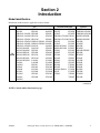
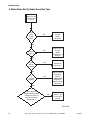
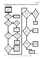
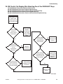
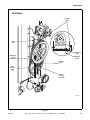
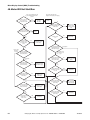
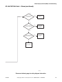
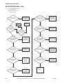
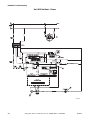
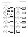
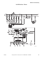
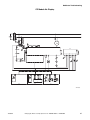
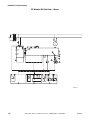
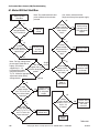
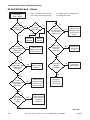
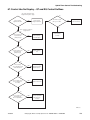
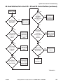
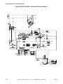
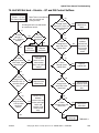
1
Troubleshooting
Drying Tumblers
50 Pound Capacity
75 Pound Capacity
Refer to Page 7 for Model Numbers
TMB795C
www.comlaundry.com
Part No. 70398301R1
June 2008
Table of
Contents
Section 1 – Safety Information ...............................................................4
Locating an Authorized Service Person ................................................6
Safety Warnings and Decals..................................................................6
Safety Precautions for Servicing Tumblers ...........................................6
Section 2 – Introduction ..........................................................................7
Model Identification ..............................................................................7
Serial Plate Location..............................................................................9
Customer Service...................................................................................9
Wiring Diagram.....................................................................................9
How a Tumbler Works ........................................................................10
Theory of Operation of Instant Electronic Ignition .............................10
Section 3 – Troubleshooting..................................................................11
1. Motor Does Not Start..................................................................12
2. Motor Overload Protector Cycles Repeatedly ............................13
3. Motor Runs But Cylinder Does Not Turn...................................14
4. Motor Does Not Stop ..................................................................15
5. Heating Element Does Not Heat or Burner Does Not Ignite......16
6. Igniter Does Not Shut Off After Gas Ignition — Gas Burner ....18
7. Heating Element or Burner Shuts Off Prematurely ....................19
8. Heating Element or Burner Repeatedly Cycles Off On
High Limit Thermostat................................................................20
9. Heating Element or Burner Does Not Shut-Off..........................21
10. Clothes Do Not Dry ....................................................................22
11. Tumbler Overheating ..................................................................23
12. Burners Not Burning Properly — Gas Models...........................24
13. Loading Door Opens During Operation......................................25
14. Tumbler Runs But No Steam To Coils — Steam Models ..........26
15. Water In Steam Line — Steam Models ......................................27
16. Door Open Light and Display Flash With Door Closed –
Electronic Control Models ..........................................................28
17. Display Shows “SH” and Signals Sounds – Electronic Control
Models.........................................................................................29
18. Display Shows “OP” and Signal Sounds Three Minutes After
Tumbler is Started – Electronic Control Models ........................30
19. Tumbler Will Not Start, Time on Drying Timer, Door Closed –
Manual Timer Models ................................................................31
20. Motor Runs, Time on Drying Timer But No Heat......................33
21. No Main Burner Flame, Igniter Does Not Spark ........................35
22. Steam OM Control: No Heat With Cycle Selected, Unit Running
and Calling For Heat ...................................................................36
23. OM and RM Control: No Start With Cycle Selected, Start Button
Pressed and Door Closed ............................................................37
24. OM Control: No Display After Selecting One of the ON/SELECT
Keys ............................................................................................39
25. Electric OM Control: No Heat With Cycle Selected, Unit Running
and Calling For Heat ...................................................................40
© Copyright 2008, Alliance Laundry Systems LLC
All rights reserved. No part of the contents of this book may be reproduced or transmitted in any form or by any means without
the expressed written consent of the publisher.
70398301
© Copyright, Alliance Laundry Systems LLC – DO NOT COPY or TRANSMIT
1
26. Gas OM Control: No Heat With Cycle Selected, Unit Running and
Calling For Heat..........................................................................42
27. OM Control: No Fan Motor Rotation With Cycle Selected and
Start Pressed................................................................................44
28. OM Reversing Control: No Cylinder Rotation or Reversing
Capabilities..................................................................................46
29. CD Control: No Start With Vend Satisfied and Start Button
Pressed In ....................................................................................48
30. CD Control: No Heat With Vend Satisfied and Unit Running ...50
31. CD Control: No Start With Vend Satisfied and
Start Button Pushed.....................................................................52
Section 4 – Adjustments ........................................................................54
32. Main Gas Burner Air Inlet Shutters (Gas Models) .....................54
33. Airflow Switch (Gas and Electric Models).................................55
34. Loading Door Strike....................................................................57
35. Drive Belt Tension ......................................................................57
36. Cylinder Clearance......................................................................60
Section 5 – Micro Display Control (MDC)
Troubleshooting .....................................................................................61
37. Coins Ignored When Entered......................................................61
38. Control Has No Display..............................................................62
39. Door Open Indicator ...................................................................64
40. Motor Will Not Start/Run ...........................................................66
41. Unit Will Not Heat – Gas............................................................69
42. Unit Will Not Heat – Steam........................................................72
43. Unit Will Not Heat – Electric .....................................................75
44. Error Codes .................................................................................78
Section 6 – NetMaster Troubleshooting ..............................................79
45. No Infrared Communication .......................................................80
46. Coins Ignored When Entered......................................................81
47. No Display ..................................................................................82
48. “Door Open” Indicator................................................................84
49. No Start/Run ...............................................................................86
50. Unit Will Not Heat – Gas............................................................88
51. Unit Will Not Heat – Steam........................................................91
52. Unit Will Not Heat – Electric .....................................................93
53. CE Models No Display ...............................................................96
54. CE Models “Door Open” Indicator.............................................98
55. CE Models No Start/Run ..........................................................100
56. CE Models Will Not Heat – Gas...............................................102
57. CE Models Will Not Heat – Steam...........................................105
58. CE Models Will Not Heat – Electric ........................................107
2
© Copyright, Alliance Laundry Systems LLC – DO NOT COPY or TRANSMIT
70398301
Section 7 – On Premise Micro Control (OM)
Troubleshooting ...................................................................................110
59. Control Has No Display............................................................111
60. Door Open Indicator .................................................................113
61. Motor Will Not Start/Run .........................................................116
62. Unit Will Not Heat – Gas..........................................................119
63. Unit Will Not Heat – Steam......................................................122
64. Unit Will Not Heat – Electric ...................................................124
65. Error Codes ...............................................................................127
Section 8 – Hybrid Timer Control Troubleshooting ........................128
66. Coins Ignored When Entered....................................................128
67. Control Has No Display – QT and RQ Control Suffixes..........129
68. Display Flashes “dr” With Door Closed – QT and RQ Control
Suffixes .....................................................................................131
69. Vend Satisfied, No In Use LED – SD and SX
Control Suffixes ........................................................................134
70. In Use LED Lit, No Motor Run – SD and SX
Control Suffixes ........................................................................137
71. Motor Will Not Start/Run – SD and SX Control Suffixes........139
72. Motor Will Not Start/Run – QT and RQ Control Suffixes .......141
73. Unit Will Not Heat – Gas – SD and SX Control Suffixes ........143
74. Unit Will Not Heat – Gas – QT and RQ Control Suffixes .......146
75. Unit Will Not Heat – Electric – QT and RQ Control Suffixes .149
76. Error Codes ...............................................................................152
70398301
© Copyright, Alliance Laundry Systems LLC – DO NOT COPY or TRANSMIT
3
Section 1
Safety Information
Throughout this manual and on machine decals, you
will find precautionary statements (“CAUTION”,
“WARNING”, and “DANGER”) followed by specific
instructions. These precautions are intended for the
personal safety of the operator, user, servicer, and those
maintaining the machine.
DANGER
Danger indicates an imminently hazardous
situation that, if not avoided, will cause
severe personal injury or death.
WARNING
Warning indicates a hazardous situation
that, if not avoided, could cause severe
personal injury or death.
In the interest of safety, some general precautions
relating to the operation of this machine follow.
WARNING
• Failure to install, maintain and/or operate
this product according to the
manufacturer’s instructions may result in
conditions which can produce serious
injury, death and/or property damage.
• Do not repair or replace any part of the
product or attempt any servicing unless
specifically recommended or published in
this Service Manual and unless you
understand and have the skills to carry
out the servicing.
• Whenever ground wires are removed
during servicing, these ground wires
must be reconnected to ensure that the
product is properly grounded and to
reduce the risk of fire, electric shock,
serious injury or death.
CAUTION
W006R2
Caution indicates a hazardous situation
that, if not avoided, may cause minor or
moderate personal injury or property
damage.
Additional precautionary statements (“IMPORTANT”
and “NOTE”) are followed by specific instructions.
IMPORTANT: The word “IMPORTANT” is used
to inform the reader of specific procedures where
minor machine damage will occur if the procedure
is not followed.
NOTE: The word “NOTE” is used to communicate
installation, operation, maintenance or servicing
information that is important but not hazard
related.
4
© Copyright, Alliance Laundry Systems LLC – DO NOT COPY or TRANSMIT
70398301
Safety Information
IMPORTANT INFORMATION: During the
lifetime of a tumbler, it may require service. The
information contained in this manual was written
and is intended for use by qualified service
technicians who are familiar with the safety
procedures required in the repair of a tumbler, and
who are equipped with the proper tools and testing
equipment.
NOTE: The WARNING and IMPORTANT
instructions appearing in this manual are not meant
to cover all possible conditions and situations that
may occur. It must be understood that common
sense, caution and carefulness are factors which
CANNOT be built into this tumbler. These factors
MUST BE supplied by the person(s) installing,
maintaining or operating the tumbler.
Always contact your dealer, distributor, service agent
or the manufacturer on any problems or conditions you
do not understand.
WARNING
To reduce the risk of electric shock, fire,
explosion, serious injury or death:
• Disconnect electric power to the tumbler
before servicing.
• Never start the tumbler with any guards/
panels removed.
• Whenever ground wires are removed
during servicing, these ground wires
must be reconnected to ensure that the
tumbler is properly grounded.
W240
WARNING
Repairs that are made to your products by
unqualified persons can result in hazards
due to improper assembly or adjustments
subjecting you or the inexperienced person
making such repairs to the risk of serious
injury, electrical shock or death.
W007
CAUTION
If you or an unqualified person perform
service on your product, you must assume
the responsibility for any personal injury or
property damage which may result. The
manufacturer will not be responsible for
any injury or property damage arising from
improper service and/or service
procedures.
W008
70398301
© Copyright, Alliance Laundry Systems LLC – DO NOT COPY or TRANSMIT
5
Safety Information
Locating an Authorized Service
Person
Alliance Laundry Systems is not responsible for
personal injury or property damage resulting from
improper service. Review all service information
before beginning repairs.
Warranty service must be performed by an
authorized technician, using authorized factory
parts. If service is required after the warranty
expires, Alliance Laundry Systems also
recommends contacting an authorized technician
and using authorized factory parts.
Safety Warnings and Decals
SAFETY WARNINGS and decals have been provided
in key locations to remind you of important precautions
for the safe operation and maintenance of your tumbler.
Please take the time to review these warnings before
proceeding with service work.
All decals have been designed and applied to withstand
washing and cleaning. Decals should be checked
periodically to be sure they have not been damaged,
removed, or painted.
6
Safety Precautions for Servicing
Tumblers
Prior to servicing tumbler:
• Disconnect electrical service and “lockout” to
prevent unintentional connection.
• Shut off supply gas valve.
• Allow machine to cool prior to servicing.
After servicing tumbler:
• Control/access panels must be reinstalled.
• Motor/drive/belt guards must be reinstalled.
• Contactor/junction/accessory box covers must
be reinstalled.
• Use a non-corrosive leak detection solution to
check all pipe connections for gas leaks. DO
NOT USE AN OPEN FLAME TO CHECK
FOR GAS LEAKS!
• The loading door switch, lint door switch and
airflow switch must be operating properly.
© Copyright, Alliance Laundry Systems LLC – DO NOT COPY or TRANSMIT
70398301
Section 2
Introduction
Model Identification
Information in this manual is applicable to these models:
AT050L
AT050N
CHD50G2-CA050L
CHD50G2-CA050N
CHD50G2-CT050L
CHD50G2-CT050N
CHD50G2-CU050L
CHD50G2-CU050N
DR50G2-BA050L
DR50G2-BA050N
DR50G2-BT050L
50
Pound DR50G2-BT050N
DR50G2-BU050L
DR50G2-BU050N
GA050L
GA050N
GT050L
GT050N
GU050L
GU050N
HA050L
HA050N
Gas
HT050D
HT050L
HT050N
HU050L
HU050N
IPD50G2-IT050L
IPD50G2-IT050N
KA050L
KA050N
KT050L
KT050N
KU050L
KU050N
LA050L
LA050N
LT050L
LT050N
LU050L
LU050N
NT050L
NT050N
PA050L
PA050N
PT050L
PT050N
PU050L
PU050N
SA050L
SA050N
ST050D
ST050L
ST050N
SU050L
SU050N
UA050L
UA050N
UT050L
UT050N
UU050L
UU050N
YT050L
YT050N
Steam/Thermal Oil
KT050T
AT050S
KU050S
BT050T
KU050T
BU050T
CHD50S2-CT050S LT050S
CHD50S2-CU050S LT050T
LU050S
CT050T
LU050T
CU050T
DR50S2-BT050S PT050S
DR50S2-BU050S PT050T
PU050S
GT050S
PU050T
GT050T
ST050S
GU050S
ST050T
GU050T
SU050S
HT050S
SU050T
HT050T
UT050S
HU050S
UT050T
HU050T
IPD50S2-IT050S UU050S
UU050T
IT050T
YT050S
KT050S
YT050T
Electric
AT050E
CHD50E2-CT050E
CHD50E2-CU050E
DR50E2-BT050E
DR50E2-BU050E
GT050E
GU050E
HT050E
HU050E
IPD50E2-IT050E
KT050E
KU050E
LT050E
LU050E
PT050E
PU050E
ST050E
SU050E
UT050E
UU050E
YT050E
(continued)
NOTE: Control suffixes listed on next page.
70398301
© Copyright, Alliance Laundry Systems LLC – DO NOT COPY or TRANSMIT
7
Introduction
AT075L
AT075N
CHD75G2-CA075L
CHD75G2-CA075N
CHD75G2-CT075L
CHD75G2-CT075N
CHD75G2-CU075L
CHD75G2-CU075N
DR75G2-BA075L
DR75G2-BA075N
DR75G2-BT075L
75
DR75G2-BT075N
Pound
DR75G2-BU075L
DR75G2-BU075N
GA075L
GA075N
GT075L
GT075N
GU075L
GU075N
HA075L
HA075N
HT075D
Gas
HT075L
HT075N
HU075L
HU075N
IPD75G2-IT075L
IPD75G2-IT075N
KA075L
KA075N
KT075L
KT075N
KU075L
KU075N
LA075L
LA075N
LT075L
LT075N
LU075L
LU075N
NT075L
NT075N
PA075L
PA075N
PT075L
PT075N
PU075L
PU075N
SA075L
SA075N
ST075D
ST075L
ST075N
STF75L
STF75N
SU075L
SU075N
UA075L
UA075N
UT075L
UT075N
UTF75L
UTF75N
UU075L
UU075N
YT075L
YT075N
Steam/Thermal Oil
KU075T
AT075S
LT075S
BT075T
LT075T
BU075T
CHD75S2-CT075S LU075S
CHD75S2-CU075S LU075T
PT075S
CT075T
PT075T
CU075T
DR75S2-BT075S PU075S
DR75S2-BU075S PU075T
ST075S
GT075S
ST075T
GT075T
SU075S
GU075S
SU075T
GU075T
UT075S
HT075S
UT075T
HT075T
UU075S
HU075S
UU075T
HU075T
IPD75S2-IT075S YT075S
YT075T
IT075T
YU075S
KT075S
YU075T
KT075T
KU075S
Electric
AT075E
CHD75E2-CT075E
CHD75E2-CU075E
DR75E2-BT075E
DR75E2-BU075E
GT075E
GU075E
HT075E
HU075E
IPD75E2-IT075E
KT075E
KU075E
LT075E
LU075E
PT075E
PU075E
ST075E
SU075E
UB075E
UT075E
UU075E
YT075E
YU075E
Includes models with the following control suffixes:
3O - DX4 OPL
DO - DMP OPL
R3 - reversing DX4 OPL
3V - DX4 vended
DV - DMP vended
RD - reversing DMP OPL
3X - DX4 prep for coin
DX - DMP prep for coin
RM - reversing OPL micro
BC - basic electronic, coin
MT - manual timer
RQ - reversing dual digital timer
BL - basic electronic, central pay
NC - NetMaster coin
RT - reversing manual timer
BX - basic electronic, prep for coin NR - NetMaster card
SD - single drop
BY - basic electronic, prep for card NX - NetMaster, prep for coin
SX - single drop, prep for coin
CD - rotary coin drop
NY - NetMaster, prep for card
ZC - NetMaster network, coin
CX - prep for coin
OM - OPL micro
ZR - NetMaster network, card
CY - prep for card
QT - dual digital timer
ZX - NetMaster network, prep for coin
ZY - NetMaster network, prep for card
8
© Copyright, Alliance Laundry Systems LLC – DO NOT COPY or TRANSMIT
70398301
Introduction
Serial Plate Location
When calling or writing about your product, be sure to
mention model and serial numbers. Model and serial
numbers are found on serial plate on the rear of
machine and inside door.
Serial
Plate
TMB803N
Customer Service
If literature or replacement parts are required, contact
the source from which the machine was purchased or
contact Alliance Laundry Systems at (920) 748-3950
for the name and address of the nearest authorized parts
distributor.
For technical assistance, call (920) 748-3121.
Wiring Diagram
The wiring diagram is located inside the junction or
contactor box.
Models starting Serial No. 0309____ or later will have
the wiring diagram part number in the lower portion of
the electrical data on the serial plate.
70398301
© Copyright, Alliance Laundry Systems LLC – DO NOT COPY or TRANSMIT
9
Introduction
How a Tumbler Works
Theory of Operation of Instant
Electronic Ignition
IMPORTANT: The Non-CE Marked Instant
Electronic Ignition system will attempt to light the
gas by sparking for approximately 15 seconds. If
gas ignition does not take place within
approximately 15 seconds, the Instant Electronic
Ignition control will go into safety lockout and the
valve will no longer open until Instant Electronic
Ignition control is reset. To reset Instant Electronic
Ignition control, remove power from control by
opening and closing the tumbler door. If condition
persists, check that the gas shut-off valve is in “on”
position and that the gas service is properly
connected.
1
2
3
If condition persists:
T001CE3A
A tumbler uses heated air to dry loads of laundry.
1. Check resistance of high tension lead
(approximately 1000 ohms/inch), and replace if
not within resistance range.
2. Check voltage present at valve.
1
When the motor is started, the exhaust fan pulls
room temperature air in through the air intake at
the rear of the tumbler and over the heat source
(burner flame for gas, heating element for
electric, and coil for steam).
2
The heated air moves into the cylinder, where it is
circulated through the wet load by the tumbling
action of the cylinder.
3
The air then passes through the lint filter, exhaust
fan, and is vented to the outdoors.
10
3. Check that machine is properly grounded.
4. Check the gap between igniter and burner tube
(gap should be 1/4-3/8 inch).
5. Check that burner ports are not blocked or
plugged under the igniter.
© Copyright, Alliance Laundry Systems LLC – DO NOT COPY or TRANSMIT
70398301
Section 3
Troubleshooting
WARNING
To reduce the risk of electric shock, fire, explosion, serious injury or death:
• Disconnect electric power to the tumbler before servicing.
• Close gas shut-off valve to gas tumbler before servicing.
• Close steam valve to steam tumbler before servicing.
• Never start the tumbler with any guards/panels removed.
• Whenever ground wires are removed during servicing, these ground wires must be
reconnected to ensure that the tumbler is properly grounded.
W002
IMPORTANT: Refer to appropriate wiring
diagram for aid in testing tumbler components.
70398301
© Copyright, Alliance Laundry Systems LLC – DO NOT COPY or TRANSMIT
11
Troubleshooting
1. Motor Does Not Start
Motor does
not start
Yes
Is electrical
power off or
have any fuses
blown?
No
Is loading door
open or is door
switch
inoperative?
Check power
and fuses.
Replace fuses
if necessary.
Close door or
test switch and
replace if
inoperative.
Non-Metered
Models: Is
timer set
properly?
Yes
Test timer and relay and
replace if inoperative.
No
Yes
Close lint door,
confirm switch
is positioned to
actuate with
door closed.
Is lint door
open or is lint
door switch
inoperative?
Yes
Non-Metered
Models: Are the
timer or relay
inoperative?
Yes
Check that proper
coins are inserted.
No
Metered Models:
Are proper coins
inserted in
accumulator?
Replace trunnion
housing bearings.
Is trunnion shaft
assembly
binding in
trunnion housing
bearings?
No
Turn drying timer clockwise
to desired setting.
No
Yes
No
No
Have motor tested and
replace if inoperative.
Is motor
inoperative?
Yes
Press start switch or
test switch and replace
if inoperative.
No
Yes
Turn knob clockwise to
its full limit of travel.
Metered CD
Models: Is the
accumulator knob
improperly set
after coins were
inserted?
Yes
Test run switch and
replace if inoperative.
No
Is start
circuit
incomplete?
No
Yes
Yes
Replace
bearings.
Is idler shaft
binding in idler
housing
bearings?
Yes
No
12
Metered CD
Models: Is run
switch
(accumulator)
inoperative?
Is there
broken,
loose or
incorrect
wiring?
No
TMB1873S
© Copyright, Alliance Laundry Systems LLC – DO NOT COPY or TRANSMIT
Yes
Refer to wiring
diagram
located inside
contactor box.
70398301
Troubleshooting
2. Motor Overload Protector Cycles Repeatedly
Motor overload
protector
cycles
repeatedly
Is voltage
incorrect?
Yes
Refer to the
Installation
Manual for
electrical
requirements.
No
Is clothes
load too
large?
Yes
No
Is clothes
cylinder
binding?
Yes
No
Is wiring
inadequate?
Yes
Remove part of
load.
Check cylinder
for binding.
Refer to
Adjustments
Section for
cylinder
adjustment.
Check with an
electrician to
ensure that
wiring is
adequate.
No
Is make-up
air
inadequate?
Yes
Refer to
Installation
Manual for
make-up air
requirements.
No
Has lint
built up?
Yes
Clean lint
accumulation
on and around
motor.
No
Is there broken,
loose or
incorrect wiring?
Yes
Refer to wiring
diagram
located inside
contactor box.
TMB1874S
70398301
© Copyright, Alliance Laundry Systems LLC – DO NOT COPY or TRANSMIT
13
Troubleshooting
3. Motor Runs But Cylinder Does Not Turn
Motor runs but
cylinder does
not turn
Is motor
drive
pulley
loose?
Confirm key is
in place,
tighten
setscrews.
Yes
No
Is sheave
loose?
Confirm key is
in place,
tighten
setscrews and
bushing.
Yes
No
Is belt
broken
or loose?
Yes
Replace or
adjust belt.
No
Is
cylinder
binding?
Check cylinder
for binding.
Refer to
Adjustments
Section for
proper cylinder
adjustment.
Yes
No
Does cylinder turn
counterclockwise when
viewed from front of
machine (3 Phase
models only)?
Yes
Switch power
leads L1 and
L2 to correct
rotation.
TMB1875S
14
© Copyright, Alliance Laundry Systems LLC – DO NOT COPY or TRANSMIT
70398301
Troubleshooting
4. Motor Does Not Stop
Motor does not
stop
Is door
switch
inoperative?
Yes
Test switch and
replace if
inoperative.
No
Non-Metered
Models: Is timer
or relay
inoperative?
Yes
Test timer and
relay and
replace if
inoperative.
No
Metered
Models: Is
accumulator
inoperative?
Yes
Test
accumulator
and replace if
inoperative.
No
Is wiring
incorrect?
Yes
Refer to wiring
diagram
located inside
contactor box.
No
Is motor relay
or motor
contactor
inoperative?
Yes
Check
relay/contactor
and replace if
inoperative.
TMB1876S
70398301
© Copyright, Alliance Laundry Systems LLC – DO NOT COPY or TRANSMIT
15
Troubleshooting
5. Heating Element Does Not Heat or Burner Does Not Ignite
Heating element
does not heat or
burner does not
ignite
Yes
Is thermistor
inoperative?
Is there
improper or
inadequate
exhaust or
make-up air?
Yes
Refer to
Installation
Manual for
exhaust and
make-up air
requirements.
No
Are there
blown fuses
or tripped
circuit
breakers?
Yes
Check fuses
or circuit
breakers.
Test thermistor by
removing harness from
thermistor terminals.
Check resistance across
terminals, should read
approximately 50,000
Ohms at 77°F.
Resistance should
decrease with a
temperature increase.
Replace thermistor if
inoperative.
No
Electric Models:
Are heating
elements or
contactors
inoperative?
Yes
No
No
Is drying
timer not
selected or
inoperative?
Yes
Set drying
timer or
replace if
necessary.
Gas Models:
Is gas supply
insufficient?
Yes
Check heat
contactors
and elements.
Replace if
necessary.
Open partially closed gas
shut-off valve, or correct
low gas pressure. Check
inlet pressure and
compare to pressure
specified on serial plate.
If pressure cannot be
obtained, contact gas
supplier.
No
No
Is "No Heat"
selected on
control?
Yes
Select
temperature
option.
No
Is control
relay
inoperative?
Gas Models:
Are orifices
incorrect?
Yes
No
Yes
Test relay and
replace if
inoperative.
Continued on
next page
No
16
Tumbler is equipped
for type of gas
specified
on serial plate at
0-2,000 feet altitude.
Refer to Installation
Manual .
© Copyright, Alliance Laundry Systems LLC – DO NOT COPY or TRANSMIT
TMB1877S-a
70398301
Troubleshooting
5. Heating Element Does Not Heat or Burner Does Not Ignite (continued)
Continued from
previous page
Gas Models:
Are gas valve
coils
inoperative?
Yes
Test coils and
replace if
available as a
service part,
otherwise
replace valve.
No
Gas and
Electric
Models: Is
airflow switch
inoperative?
Clean lint
compartment after
every eight hour shift.
Check back draft
damper for foreign
objects, lint
accumulation or other
causes that may
prevent damper from
opening.
Check ductwork for lint
build-up. Refer to
Installation Manual to
ensure that ductwork
and make-up air
openings are sized
properly.
Check exhaust outlet. If
a screen has been
installed on the outlet, it
may be clogged with
lint or frozen over in
winter. NEVER install a
screen over the
exhaust outlet.
Yes
No
Gas Models:
Is igniter
inoperative?
Yes
Test igniter and
replace if
inoperative.
No
Gas Models:
Is igniter
control
inoperative?
Yes
Test igniter
control and
replace if
inoperative.
No
Yes
Refer to
Adjustments
Section for
airflow switch
adjustment.
No
No
Gas and Electric
Models: Is high
limit thermostat
inoperative?
Gas and Electric
Models: Is airflow
switch out of
adjustment?
Yes Test thermostat
and replace if
inoperative.
Is lint door
panel not
closed
properly?
Yes
Open lint door
panel. Place lint
door panel back on
tumbler ensuring a
tight fit.
No
Is there
broken, loose
or incorrect
wiring?
Yes
Refer to wiring
diagram
located inside
contactor box.
TMB1877S-b
70398301
© Copyright, Alliance Laundry Systems LLC – DO NOT COPY or TRANSMIT
17
Troubleshooting
6. Igniter Does Not Shut Off After Gas Ignition — Gas Burner
Igniter does not
shut off after
gas
ignition - gas
burner
Is tumbler not
properly equipped for
type of gas being
used?
Yes
Tumbler is equipped for
type of gas specified on
serial plate at 0-2,000
feet altitude. Refer to
Installation Manual.
No
Is there
insufficient gas
supply?
Yes
Open partially
closed gas shut-off
valve or correct low
gas pressure.
No
Is burner flame
adjusted
improperly?
Yes
Refer to
Adjustments
Section for
recommended
burner flame
adjustment.
No
Is electrode assembly
incorrectly installed?
Yes
Check
assembly for
correct
alignment.
No
Is igniter control
inoperative?
Yes
Test igniter
control and
replace if
inoperative.
No
Is wiring
incorrect?
Yes
Refer to wiring
diagram
located inside
contactor box.
TMB1878S
18
© Copyright, Alliance Laundry Systems LLC – DO NOT COPY or TRANSMIT
70398301
Troubleshooting
7. Heating Element or Burner Shuts Off Prematurely
Heating
element or
burner shuts off
prematurely
Is there improper or
inadequate exhaust
and/or make-up air?
Yes
Refer to
Installation
Manual for exhaust
and make-up air
requirements.
No
Gas Models: Is
there insufficient
gas supply?
Yes
Open partially
closed gas shut-off
valve or correct low
pressure.
No
Gas Models: Is tumbler
not properly equipped
for type of gas used?
Yes
Tumbler is equipped for
type of gas specified on
serial plate at 0-2,000
feet altitude. Refer to
Installation Manual.
No
Gas Models: Is
burner flame
improperly adjusted?
Yes
Refer to
Adjustments
Section for burner
flame adjustment.
No
Is high limit
thermostat
cycling off?
Yes
Refer to
Paragraph 8.
No
Is there
broken, loose
or incorrect
wiring?
Yes
Refer to wiring
diagram
located inside
contactor box.
TMB1879S
70398301
© Copyright, Alliance Laundry Systems LLC – DO NOT COPY or TRANSMIT
19
Troubleshooting
8. Heating Element or Burner Repeatedly Cycles Off On High Limit
Thermostat
Heating element or
burner repeatedly
cycles off on high
limit thermostat
Is external exhaust
system longer than
recommended or is
there inadequate
make-up air?
Refer to
Installation
Yes
Manual for
exhaust and
make-up air
requirements.
Is high limit
thermostat
cycling at too
low a
temperature?
Yes
Replace
thermostat.
No
Is lint
screen
clogged?
Yes
Remove screen
and clean. Lint
screen and
compartment
should be cleaned
after every eight
hour shift.
No
Is there lint
in tumbler
ducts?
Yes
Clean tumbler
ducts.
Is lint door
panel not
closed
properly?
Yes
Yes
Open lint door
panel, place lint
door panel back
on tumbler
ensuring a tight fit.
No
Is backdraft
damper not
operating?
No
Is there lint
in external
exhaust
system?
No
Yes
Check for
foreign
objects, lint
accumulation
or other
possible
obstructions.
Disassemble
exhaust
system and
clean.
TMB1880S
No
20
© Copyright, Alliance Laundry Systems LLC – DO NOT COPY or TRANSMIT
70398301
Troubleshooting
9. Heating Element or Burner Does Not Shut-Off
Heating element or
burner does not
shut-off
Gas Models: Are
there impurities on
gas valve seat,
preventing valve
from closing?
Yes
Replace gas
valve.
Yes
Replace timer,
relay or
contactor.
No
Is drying
timer, relay or
contactor
inoperative?
No
Is wiring
incorrect?
Yes
Refer to wiring
diagram
located inside
contactor box.
TMB1881S
70398301
© Copyright, Alliance Laundry Systems LLC – DO NOT COPY or TRANSMIT
21
Troubleshooting
10. Clothes Do Not Dry
Clothes do
not dry
Is heat
source
inoperative?
Yes
Refer to
Paragraph 5.
Does heat
source shutoff
prematurely?
Yes
Refer to
Paragraph 7.
No
No
Is there too
much water in
articles being
dried?
Yes
Remove
excess water.
Is drying
timer
improperly
set?
Yes
Set selector for
higher setting.
No
No
Is clothes
load too
large?
Yes
Remove part of
load.
No
Is exhaust
system
improper or
inadequate?
Is voltage
incorrect?
Yes
Refer to
Installation
Manual for
electrical
requirements.
No
Yes
Refer to
Installation
Manual for
exhaust
requirements.
Is make-up
air
inadequate?
Yes
Refer to
Installation
Manual for
make-up air
requirements.
No
TMB1882S
22
© Copyright, Alliance Laundry Systems LLC – DO NOT COPY or TRANSMIT
70398301
Troubleshooting
11. Tumbler Overheating
Tumbler
overheating
Gas Models:
Are main
burner orifices
incorrect?
Replace orifices.
Refer to the
Yes
Installation
Manual for burner
orifice
requirements.
No
No
Gas Models:
Is gas
pressure too
high?
Is exhaust
system
restricted or
inadequate?
Yes
Gas pressure
must be as
specified on
serial plate.
Is
thermistor
inoperative?
No
Is make-up air
inadequate?
Remove
obstruction or lint
build-up from
exhaust
ductwork.
Yes
Refer to
Installation
Manual for exhaust
system
requirements.
Yes
Refer to
Installation
Manual for
make-up air
requirements.
No
Test thermistor by
removing harness from
thermistor terminals. Check
resistance across
Yes
terminals, should read
approximately 50,000
Ohms at 77˚F. Resistance
should decrease with a
temperature increase.
Replace thermistor if
inoperative.
No
Is there lint
accumulation?
Yes
Remove lint.
Is cabinet
limit or burner
limit
thermostat
inoperative?
Check
thermostats
Yes
with Ohm
meter and
replace if open.
No
TMB1883S
70398301
© Copyright, Alliance Laundry Systems LLC – DO NOT COPY or TRANSMIT
23
Troubleshooting
12. Burners Not Burning Properly — Gas Models
Burners not
burning
properly - Gas
Models
Are burner air
shutters incorrectly
adjusted?
Yes
Refer to
Adjustments
Section for
proper flame
adjustment.
No
Is there dirt
in burners?
Disassemble
burners and
blow out the
dirt.
Yes
No
Is gas pressure too
high or too low?
Yes
Check serial
plate on back
of the tumbler
for correct gas
pressure.
No
Are orifices incorrect?
Yes
Tumbler is equipped for
type of gas specified on
serial plate at 0-2,000
feet altitude. Refer to
Installation Manual.
No
Is make-up air
inadequate?
Yes
Refer to
Installation
Manual for proper
make-up air
requirements.
No
Is exhaust duct
restricted or blocked?
Yes
Disassemble and
clean exhaust
system.
TMB1884S
24
© Copyright, Alliance Laundry Systems LLC – DO NOT COPY or TRANSMIT
70398301
Troubleshooting
13. Loading Door Opens During Operation
Loading door
opens during
operation
Is door strike
improperly
adjusted?
Yes
Refer to
Adjustments
Section for
door strike
adjustment.
No
Is tumbler
improperly
leveled?
Yes
Refer to
Installation
Manual for
leveling leg
adjustment.
TMB1885S
70398301
© Copyright, Alliance Laundry Systems LLC – DO NOT COPY or TRANSMIT
25
Troubleshooting
14. Tumbler Runs But No Steam To Coils — Steam Models
Tumbler runs but
no steam to
coils - Steam
Models
Are valves
closed?
Yes
No
Is steam trap
blocked?
Yes
Check all
valves in
supply and
return lines,
make sure they
are open.
Remove trap
and clean.
Replace if
inoperative.
No
Is solenoid valve
inoperative?
Yes
Check
operation of
solenoid valve.
No
Is check valve
incorrectly installed?
Yes
Check for inlet and
outlet markings on
check valve and
invert if necessary.
No
Is strainer clogged?
Yes
Remove strainer
and clean.
No
Is timer or thermistor
inoperative?
Yes
Test timer. Test thermistor by removing
harness from thermistor terminals. Check
resistance across terminals, should read
approximately 50,000 Ohms at 77˚F.
Resistance should decrease with a
temperature increase. Replace either if
inoperative.
TMB1886S
26
© Copyright, Alliance Laundry Systems LLC – DO NOT COPY or TRANSMIT
70398301
Troubleshooting
15. Water In Steam Line — Steam Models
Water in steam
line - Steam
Models
Is steam
piping
installed
incorrectly?
Yes
Refer to
Installation
Manual for
steam
requirements.
No
Is trap
functioning
improperly?
Yes
Check trap for size
and capacity. If trap is
dirty or sluggish clean
thoroughly or replace.
Check return line for
high back pressure.
TMB1887S
70398301
© Copyright, Alliance Laundry Systems LLC – DO NOT COPY or TRANSMIT
27
Troubleshooting
16. Door Open Light and Display Flash With Door Closed – Electronic Control
Models
Door open light and
display flash with door
closed - Electronic
Control Models
Is door switch
faulty?
Yes
Replace door
switch.
Yes
Replace lint
panel switch.
No
Is lint panel
switch faulty?
No
Is electrical service
connected incorrectly?
Yes
Check service connections to
terminal block in junction box.
For 120 or 240 Volt tumblers,
neutral wire must be
connected to terminal marked
"NEUT". On single phase
tumblers, hot wire must be
connected to terminal marked
"L1". A ground wire must be
secured to the ground screw in
the junction box.
TMB1888S
28
© Copyright, Alliance Laundry Systems LLC – DO NOT COPY or TRANSMIT
70398301
Troubleshooting
17. Display Shows “SH” and Signals Sounds – Electronic Control Models
Display shows
"SH" and signals
sounds - Electronic
Control Models
Is temperature
at sensor over
191˚F (88.3˚C)?
Yes
Allow tumbler to
cool and press
ON/SELECT pad. If
display still shows
"SH", replace
sensor.
No
Has temperature
sensor shorted?
Yes
Replace
temperature
sensor.
TMB1916S
70398301
© Copyright, Alliance Laundry Systems LLC – DO NOT COPY or TRANSMIT
29
Troubleshooting
18. Display Shows “OP” and Signal Sounds Three Minutes After Tumbler is
Started – Electronic Control Models
Display shows "OP"
and signal sounds
three minutes after
tumbler is
started - Electronic
Control Models
Is temperature
at sensor under
24˚F (-4.4˚C)?
Yes
If the temperature of
the tumbler is above
24˚F (-4.4˚C), replace
temperature sensor.
No
Is temperature
sensor open?
Yes
Replace
temperature
sensor.
TMB1917S
30
© Copyright, Alliance Laundry Systems LLC – DO NOT COPY or TRANSMIT
70398301
Troubleshooting
19. Tumbler Will Not Start, Time on Drying Timer, Door Closed – Manual
Timer Models
Tumbler will not
start, time on
drying timer, door
closed - Manual
Timer Models
Is there 24
volts into door
switch?
No
Check electrical
service to tumbler
(transformer/fuses).
Is there 24 volts
across coil
terminals of
control relay?
Is there 24
volts on
terminal B
of drying
timer?
No
Yes
Yes
Is there 24
volts out of
door switch?
Yes
No
Yes
Has door
switch been
actuated?
Yes
Replace door
switch.
Is there 24
volts out of
lint panel
switch?
No
Has lint panel
switch been
actuated?
Is there 24
volts on
terminal 5 of
control relay?
No
Replace relay.
Yes
Yes
Yes
Replace lint
panel switch.
Is there 24
volts at
terminal 3 of
control relay?
Replace
timer.
No
Check lint
panel switch for
broken wire or
poor
connection at
harness plug.
Is there 24
volts into push
-to-start
switch?
No
Yes
Continued on
next page.
Yes
70398301
Check for
broken wire
from control
relay terminal
5.
TMB1889S-a
© Copyright, Alliance Laundry Systems LLC – DO NOT COPY or TRANSMIT
31
Troubleshooting
19. Tumbler Will Not Start, Time on Drying Timer, Door Closed – Manual
Timer Models (continued)
Continued from
previous page.
Press push-tostart switch. Is
there 24 volts
out of push-tostart switch?
No
Replace pushto-start switch.
Are motor
connections per
wiring diagram?
No
Correct wiring.
Yes
Yes
Is there 24
volts to motor
relay coil?
No
Check for broken
wire or poor
connection at
harness plug.
No
Check
connections
and harness
continuity.
Yes
Yes
Is there line
voltage in and
out of relay?
Is there line
voltage at motor
terminals?
No
Check power
supply to
tumbler and
wires to relay.
Replace motor.
Yes
TMB1889S-b
32
© Copyright, Alliance Laundry Systems LLC – DO NOT COPY or TRANSMIT
70398301
Troubleshooting
20. Motor Runs, Time on Drying Timer But No Heat
Motor runs,
time on drying
timer but no
heat
Is there
power out of
temperature
control board?
Replace switch B
or accumulator.
Yes
Coin Switch B
Common (CD
Models): Is there
power on terminal 6
of control relay
(manual timer
models)?
Yes
Check the
ignition circuit.
Is there
power across
coil terminals
of control
relay?
Yes
No
No
Is there
power into
temperature
control board?
Yes
Replace
control relay.
Check
thermistor and
Yes cable. If OK,
replace
temperature
control board.
Is there
broken or
loose wire at
harness plug?
Yes
Repair wire.
No
No
Coin Switch B
Normally Closed
(CD Models): Is
there power on
terminal 4 of
control relay
(manual timer
models)?
Yes
Loose or
broken wire to
temperature
control board.
Is there
power into
burner high
limit
thermostat?
No
Check for
broken wire
from airflow
switch.
Yes
Continued on
next page.
No
TMB1890S-a
70398301
© Copyright, Alliance Laundry Systems LLC – DO NOT COPY or TRANSMIT
33
Troubleshooting
20. Motor Runs, Time on Drying Timer But No Heat (continued)
Continued from
previous page.
Is there
power out of
burner high
limit
thermostat?
Replace burner
high limit
thermostat.
No
Yes
Is there
power into
airflow switch?
Check for loose
or broken wire
from cabinet
limit.
No
No
Replace
thermostat.
Yes
Check for loose
or burned
connection at
harness plugs.
Is airflow
switch
closed?
Adjust airflow
switch.
Check for
broken wire
from motor
switch.
Yes
No
No
No
Yes
Is there
power out of
cabinet high
limit
thermostat?
Yes
Is there
power out
of airflow
switch?
Is there
power into
cabinet high
limit
thermostat?
Yes
Replace airflow
switch.
TMB1890S-b
34
© Copyright, Alliance Laundry Systems LLC – DO NOT COPY or TRANSMIT
70398301
Troubleshooting
21. No Main Burner Flame, Igniter Does Not Spark
No main burner
flame, igniter
does not spark
Is igniter
sparking?
Is IEI
control in
safety
lockout?
No
No
Yes
Is resistance of
high voltage lead
greater than
25,000 Ohms or
less than 5,000
Ohms?
Is igniter gap
not 5/32 in.
(.397 cm) or is
ceramic
cracked?
No
Yes
No
Yes
Yes
Open and
close door.
Is green wire
from IEI
control
connected to
ground
terminal?
No
Connect green
wire to ground
terminal.
No
Open gas shutoff valve.
Replace
IEI control.
Is there 24 volts
present on
white/black wire
from IEI control?
Yes
Yes
Is gas
shut-off
valve
open?
Re-gap or
replace
igniter.
Replace high
voltage lead.
Check gas
valve coils.
Replace as
required.
No
Replace IEI
control.
Yes
TMB1891S
70398301
© Copyright, Alliance Laundry Systems LLC – DO NOT COPY or TRANSMIT
35
Troubleshooting
22. Steam OM Control: No Heat With Cycle Selected, Unit Running and
Calling For Heat
120 Volt/60 Hertz/1 Phase and 208-240 Volt/60 Hertz/1 Phase Nonreversing
460-480 Volt/60 Hertz/3 Phase and 208-240 Volt/60 Hertz/3 Phase Reversing and Nonreversing
Steam OM Models:
No heat with cycle
selected, unit
running and calling
for heat
Is there
voltage at
H2-13?
Is there
voltage to the
input of the
motor switch?
No
Replace micro
control.
No
Correct wiring
to motor
switch.
Yes
Yes
Is there
voltage at
H2-6?
Correct wiring
between H2-6
and H2-13.
No
Is there
voltage to the
output of the
motor switch?
No
Replace motor.
Yes
Is there
voltage at
H2-5?
Check for proper
thermistor
operation. Replace
micro control if
necessary.
No
Is there
voltage across
the steam
valve coil?
Yes
Is there
voltage to the
input of the
motor relay?
No
Correct wiring
between motor
relay and micro
control.
Yes
Is there voltage
to the output of
the motor relay?
Yes
Correct wiring
to steam valve
coil.
Yes
Unit operational. If unit
still does not heat,
check steam supply.
No
Replace motor
relay.
Yes
36
No
TMB1892S
© Copyright, Alliance Laundry Systems LLC – DO NOT COPY or TRANSMIT
70398301
Troubleshooting
23. OM and RM Control: No Start With Cycle Selected, Start Button Pressed
and Door Closed
120 Volt/60 Hertz/1 Phase Gas and Steam Nonreversing
208-240 Volt/60 Hertz/1 or 3 Phase Steam Nonreversing
208-240 Volt/60 Hertz/3 Phase Electric Nonreversing
460-480 Volt/60 Hertz/3 Phase Gas, Electric and Steam Nonreversing
OM and RM Models:
No start with cycle
selected, start button
pressed and door closed
Is there
voltage to the
primary of the
transformer?
Is there
voltage to the
COM terminal
of the lint panel
switch?
No
Correct wiring
to transformer
primary.
Check fuses.
Is there 24 VAC
across terminals 2
& 3 of transformer
secondary?
No
Yes
70398301
No
Yes
No
Correct wiring
between door
switch and
transformer.
Check fuse.
Yes
Is there
voltage to the
N.O. terminal
of the door
switch?
Check lint
panel switch
for proper
operation.
Replace if
necessary.
Replace
transformer.
Yes
Is there
voltage to the
COM terminal
of the door
switch?
Yes
Is there
voltage to the
N.O. terminal of
the lint panel
switch?
Yes
Correct wiring
between lint
panel switch
and loading
door switch.
No
No
Check door
switch for
proper
operation.
Replace if
necessary.
Is there
voltage to
terminal H2-8
on the micro
control?
No
Correct wiring
between micro
control and lint
panel switch.
Yes
Is there
voltage at
terminal H2-7
on the micro
control?
No
Replace micro
control.
Yes
Continued on
next page.
TMB1893S-a
© Copyright, Alliance Laundry Systems LLC – DO NOT COPY or TRANSMIT
37
Troubleshooting
23. OM and RM Control: No Start With Cycle Selected, Start Button Pressed
and Door Closed (continued)
Continued from
previous page.
Is there
voltage across
the coil of
motor relay?
No
Correct wiring
between motor
relay and micro
control.
Yes
Is there
voltage to the
input of the
motor relay?
Yes
Is there
voltage to the
output of the
motor relay?
No
Replace motor
relay.
Yes
No
Correct wiring
between motor
relay and
supply voltage.
Does the
motor
operate?
No
Replace motor.
Yes
Unit
operational.
TMB1893S-b
38
© Copyright, Alliance Laundry Systems LLC – DO NOT COPY or TRANSMIT
70398301
Troubleshooting
24. OM Control: No Display After Selecting One of the ON/SELECT Keys
120 Volt/60 Hertz/1 Phase Gas and Steam Nonreversing
208-240 Volt/60 Hertz/1 Phase Gas and Steam Nonreversing
208-240 Volt/60 Hertz/3 Phase Gas and Steam Reversing/Nonreversing
208-240 Volt/60 Hertz/3 Phase Electric Reversing/Nonreversing
460-480 Volt/60 Hertz/3 Phase Gas, Electric and Steam Reversing/Nonreversing
OM Models: No
display after
selecting one of
the on/select keys
Is there voltage
across the
primary of the
transformer?
No
Correct wiring
between
transformer
and supply
voltage. Check
fuses.
Is there voltage
to the input of
the fuse on the
micro control?
Yes
Is there 24 VAC
across terminals 1
& 4 of
transformers
secondary?
No
Replace
transformer.
Is there 24 VAC
across terminals
H3-3 and H3-4 on
the micro control?
No
Correct wiring
between H3 and
transformer.
Replace micro
control.
Yes
Is there voltage to
the opposite side
of the fuse on the
micro control?
Yes
Yes
No
Check fuse
No making sure it
is not blown.
Replace if
necessary.
Yes
Replace micro
control.
TMB1894S
70398301
© Copyright, Alliance Laundry Systems LLC – DO NOT COPY or TRANSMIT
39
Troubleshooting
25. Electric OM Control: No Heat With Cycle Selected, Unit Running and
Calling For Heat
460-480 Volt/60 Hertz/3 Phase and 208-240 Volt/60 Hertz/3 Phase Reversing and Nonreversing
Electric OM Models:
No heat with cycle
selected, unit running
and calling for heat
Is there
voltage at
H2-13?
Is there
voltage at
white/brown
fan motor
centrifugal
switch?
No
No
Correct wiring
between relay
and motor
switch.
Replace micro
control.
Yes
Yes
Is there
voltage at
H2-6?
No
Correct wiring
between H2-6
and H2-13.
Yes
If there
voltage at
H2-5?
No
Check for proper
thermistor
operation. Replace
micro control if
necessary.
Is there
voltage at
orange/brown
fan motor
centrifugal
switch?
No
Replace motor.
Yes
Yes
Is there voltage to
terminal 14 of the
motor relay?
Correct wiring
No between motor
relay and
micro control.
Is there voltage
to cabinet limit
black wire?
Correct wiring
between fan
motor
No
centrifugal
switch and
cabinet limit
thermostat.
Yes
Yes
Is there voltage to
terminal 13 of the
motor relay?
No Replace motor
relay.
Is there
voltage out of
cabinet limit
white wire?
No
Replace
thermostat.
Yes
Yes
Continued on
next page.
TMB1895S-a
40
© Copyright, Alliance Laundry Systems LLC – DO NOT COPY or TRANSMIT
70398301
Troubleshooting
25. Electric OM Control: No Heat With Cycle Selected, Unit Running and
Calling For Heat (continued)
Continued from
previous page.
Is there
voltage to
airflow switch
orange wire
(common
terminal)?
Is there
voltage to
terminals T1,
T2 and T3 of
HC1?
Correct wiring
between
No
cabinet limit
and airflow
switch.
Yes
Is there
voltage to
terminals L1,
L2 and L3 of
HC1?
Yes
Is there voltage
to the N.O.
terminal of the
airflow switch?
No
Check for
proper airflow.
Replace
airflow switch.
Correct wiring
between HC1
and supply.
No
No
Replace HC1.
Yes
Is there
voltage across
the elements?
Correct wiring
to the
elements.
No
Yes
Is there
voltage to the
input of the
stove limit?
Correct wiring
No between stove
limit and
airflow switch.
Yes
Is there
voltage to the
output of the
stove limit?
Check for
proper airflow.
No
Replace stove
limit if
necessary.
Yes
Do the elements
produce heat?
NOTE: If elements
are glowing
bright
red/orange, there
is not enough
airflow.
No
Check for
opens or shorts
in the
elements.
Yes
Is there
voltage across
coil of HC1?
No Correct wiring
to HC1.
Yes
Unit
operational.
Yes
70398301
TMB1895S-b
© Copyright, Alliance Laundry Systems LLC – DO NOT COPY or TRANSMIT
41
Troubleshooting
26. Gas OM Control: No Heat With Cycle Selected, Unit Running and Calling
For Heat
120 Volt/60 Hertz/1 Phase and 208-240 Volt/60 Hertz/1 Phase Nonreversing
460-480 Volt/60 Hertz/3 Phase and 208-240 Volt/60 Hertz/3 Phase Reversing and Nonreversing
Gas OM Models:
No heat with cycle
selected, unit running
and calling for heat
Is there
voltage at
H2-13?
Is there
voltage to the
input of fan
motor switch?
No
Replace micro
control.
Is there
voltage at H26 of the micro
control?
No
Correct wiring
between H2-6
and H2-13 on
the micro
control.
Is there
voltage at
H2-5 of the
micro
control?
Check for proper
thermistor
operation. Replace
micro control if
necessary.
No
Is there
voltage to
input of the
motor relay?
No
Correct wiring
between motor
relay and micro
control.
Yes
Is there voltage
to the output of
the motor relay?
No Replace motor
relay.
Correct wiring
between
cabinet limit
and CR1.
Yes
No
Replace
cabinet limit.
Yes
Is there
voltage to
COM terminal
of the airflow
switch?
Yes
Yes
Replace fan
motor.
No
Is there
voltage to the
output of the
cabinet limit?
Yes
No
Yes
Is there
voltage to the
input of the
cabinet limit?
Yes
Correct wiring
to fan motor
switch.
Yes
Is there
voltage out
from the fan
motor switch?
Yes
No
No
Correct wiring
between airflow
switch and
cabinet limit.
Continued on
next page.
TMB1896S-a
42
© Copyright, Alliance Laundry Systems LLC – DO NOT COPY or TRANSMIT
70398301
Troubleshooting
26. Gas OM Control: No Heat With Cycle Selected, Unit Running and Calling
For Heat (continued)
Continued from
previous page.
Does the
igniter
spark?
Is there
voltage to the
N.O. terminal
of the airflow
switch?
No
Check for proper
operation and
airflow. Replace
airflow switch if
necessary.
Yes
Is there
voltage to the
input of the
stove limit?
No
Correct wiring
between stove
limit and
airflow switch.
No
Yes
Is there
voltage at
terminal 1 of
the ignition
control?
No
Check for proper
gap on igniter and
check for proper
resistance of
ignition cable.
Replace if
necessary.
Replace
ignition
control.
Yes
Yes
Is there
voltage to the
output of the
stove limit?
No
Check for proper
airflow. Replace
stove limit if
necessary.
Is there
voltage
across the
gas valve?
No
Correct wiring
to gas valve.
Yes
Yes
Is there a
flame?
Is there
voltage to
terminal 2 of
the ignition
control?
No
Correct wiring
between
ignition control
and stove limit.
No
Yes
Unit
operational.
Yes
70398301
Check for gas
flow and proper
gas pressure.
Replace gas
valve or coils of
gas valve.
TMB1896S-b
© Copyright, Alliance Laundry Systems LLC – DO NOT COPY or TRANSMIT
43
Troubleshooting
27. OM Control: No Fan Motor Rotation With Cycle Selected and Start
Pressed
208-240 Volt/60 Hertz/3 Phase and 480 Volt/60 Hertz/3 Phase Electric Reversing Models
208-240 Volt/60 Hertz/3 Phase and 460-480 Volt/60 Hertz/3 Phase Gas Reversing and Steam Models
OM Models: No fan
motor rotation with
cycle selected and
start pressed
Is there voltage
across the primary
of the transformer?
If actuated
replace
inoperative
No
switch. If not
actuated adjust
switch as
needed.
Is there
voltage out of
lint panel
switch?
No
Correct wiring
to transformer.
Check fuses.
Yes
Yes
Is there
voltage to H28 of micro
control?
Correct wiring
No between micro
control and
door switch.
Yes
Is there 24 VAC
across terminals 2 &
3 of the transformer
secondary?
No
Replace
transformer.
Is there
voltage to H27 of micro
control?
No Replace micro
control.
Yes
Yes
Is there voltage
to the COM of
the door switch?
No
Correct wiring
to door switch.
Check fuse.
Is there voltage
across the coil
of the M
contactor?
No
Correct the
wiring to the M
contactor.
Yes
Yes
Is there voltage to
the N.O. terminal
of the door switch?
Check door switch
No
for proper
operation. Replace
if necessary.
Is there voltage
to L1, L2 and L3
of the M
contactor?
No
Correct wiring
between M
contactor and
supply voltage.
Yes
Is there voltage into
lint panel switch?
Correct wiring
No between door
switch and lint
panel switch.
Yes
Yes
44
Continued on
next page.
TMB1897S-a
© Copyright, Alliance Laundry Systems LLC – DO NOT COPY or TRANSMIT
70398301
Troubleshooting
27. OM Control: No Fan Motor Rotation With Cycle Selected and Start
Pressed (continued)
Continued from
previous page.
Is there voltage
to T1, T2 and T3
of the M
contactor?
No
Replace M
contactor.
Yes
Is there voltage
across L1, L2
and L3 of the
motor?
No
Correct wiring
between motor
and M
contactor.
Yes
Unit
operational.
TMB1897S-b
70398301
© Copyright, Alliance Laundry Systems LLC – DO NOT COPY or TRANSMIT
45
Troubleshooting
28. OM Reversing Control: No Cylinder Rotation or Reversing Capabilities
208-240 Volt/60 Hertz/3 Phase and 480 Volt/60 Hertz/3 Phase Electric Models
208-240 Volt/60 Hertz/3 Phase and 460-480 Volt/60 Hertz/3 Phase Gas and Steam Models
OM Reversing
Models: No
cylinder rotation or
reversing
capabilities
Is there
voltage into
lint panel
switch?
No
Correct wiring
between door
switch and lint
panel switch.
Yes
Is there voltage
across the
primary of the
transformer?
No
Correct wiring
between
transformer
and supply
voltage. Check
fuses.
Yes
Yes
Is there voltage
across terminals 2
& 3 of the
transformer
secondary?
No
Replace
transformer.
Yes
Is there voltage
to the COM of
the door switch?
No
Correct wiring
to door switch.
Check fuses.
Yes
Is there voltage
to the N.O.
terminal of the
door switch?
No
Correct wiring
and check
fuses.
Is there voltage
to H2-8 terminal
of micro control?
Continue to next
step for forward
rotation or next
page for reverse
rotation.
No Correct wiring
between micro
control and
door switch.
Yes
Make sure
unit is in the
No forward portion
of rotation.
Replace micro
control.
Forward
Rotation: Is
there voltage
to H2-3 of
micro control?
Yes
Yes
If actuated replace
No inoperative switch.
If not actuated
adjust switch as
needed.
Is there
voltage out of
lint panel
switch?
Continued on
next page.
TMB1898S-a
46
© Copyright, Alliance Laundry Systems LLC – DO NOT COPY or TRANSMIT
70398301
Troubleshooting
28. OM Reversing Control: No Cylinder Rotation or Reversing Capabilities
(continued)
Continued from
previous page.
Is there voltage
across the coil of
the reverse relay?
Is there voltage
across the coil
of the forward
relay?
No
Correct the
wiring to the
relay.
Is there voltage
to terminals L1,
L2 and L3 of the
forward relay?
No
Correct wiring
between relay
and supply
voltage.
No
Is there voltage
to terminals T1,
T2 and T3 of the
forward relay?
No
Replace
forward relay.
No
Is there voltage
across L1, L2
and L3 of the
motor?
No
Correct wiring
between motor
and forward
relay.
Yes
Replace
reversing
relay.
Yes
Is there voltage
across L1, L2 and
L3 of the motor?
Yes
Correct wiring
between relay
and supply
voltage.
Yes
Is there voltage
to terminals U, V
and W of the
reversing relay?
Yes
Correct the
wiring to the
relay.
Yes
Is there voltage
to terminals X, Y
and Z of the
reversing relay?
Yes
No
No
Correct wiring
between motor
and reversing
relay.
Yes
Does the
motor
turn?
No
Replace motor.
Yes
Continue here from
previous page for
Reverse Rotation: Is
there voltage to H2-4
of micro control?
Yes
Make sure unit
is in the
No
reverse portion
of rotation.
Replace micro
control.
Does the
cylinder
rotate?
Yes
No
Check drive
components
between motor
and cylinder.
Unit
operational.
TMB1898S-b
70398301
© Copyright, Alliance Laundry Systems LLC – DO NOT COPY or TRANSMIT
47
Troubleshooting
29. CD Control: No Start With Vend Satisfied and Start Button Pressed In
NOTE: All voltage checks are referenced to neutral unless stated otherwise.
CD Models: No
start with vend
satisfied and start
button pressed in
Is there voltage
to NC terminal
of switch A?
With the door
closed, is there
voltage to the
N.O. terminal of
the door switch?
No
Correct wiring
between L1
and switch A.
No
Check door
switch for
proper
operation,
replace if
necessary.
Yes
Yes
Is there voltage to
the COM terminal
of switch A?
Check for proper
No operation of switch
A. Replace switch
A if necessary.
Yes
Is there
voltage at
COM of lint
panel switch?
No
Correct wiring
between door
switch and lint
panel switch.
Yes
Is there voltage
to H1-2 at time
delay board?
No
Correct wiring
between switch A
and H1-2 at time
delay board.
Is there
voltage to NO
of lint panel
switch?
No
Adjust switch
as needed.
Yes
Is there voltage
to H1-3 at time
delay board?
No
Replace time
delay board.
Yes
Is there voltage to
the common
terminal of the
door switch?
Yes
No
Correct wiring
between door
switch and
switch A.
Yes
Is there voltage
to the input side
of the Push-ToStart button?
No
Correct wiring
between start
switch and lint
panel switch.
Yes
Continued on
next page.
TMB1899S-a
48
© Copyright, Alliance Laundry Systems LLC – DO NOT COPY or TRANSMIT
70398301
Troubleshooting
29. CD Control: No Start With Vend Satisfied and Start Button Pressed In
(continued)
Continued from
previous page.
Is there
voltage to
output of push
-to-start
switch?
Is there
voltage to
motor
contactor?
No
Correct wiring
between motor
contactor and
supply.
Yes
No
Replace
switch.
Is there
voltage out of
the motor
contactor?
No
Yes
Check for
proper
operation.
Replace motor
contactor if
necessary.
Yes
Is there
voltage to the
input side of the
auxiliary contacts
on the motor
contactor?
Correct wiring
No between motor
contactor and lint
panel switch.
Is there
voltage to the
motor?
No
Correct wiring
between motor
contactor and
motor.
Yes
Yes
Is there voltage
across the coil
of the motor
control
contactor?
No
Correct wiring
between motor
contactor and
Push-To-Start
button.
Yes
If the start button
is released, does
the motor contactor
stay in the made
position?
Check for proper
operation of
motor contactor
No
and fan motor
centrifugal switch,
replace if
necessary.
Is the internal
wiring of the
motor correct
for the supply
voltage?
No
Change the
wiring
accordingly.
Yes
Thermal
overload
cycled, allow
motor to cool
and recheck.
Yes
No
Replace motor.
Unit
operational.
Yes
TMB1899S-b
70398301
© Copyright, Alliance Laundry Systems LLC – DO NOT COPY or TRANSMIT
49
Troubleshooting
30. CD Control: No Heat With Vend Satisfied and Unit Running
NOTE: All voltage checks are referenced to neutral unless stated otherwise.
CD Models: No heat
with vend satisfied
and unit running
Is there voltage to
the output of the
motor switch?
Is there
voltage to the
input of the
stove limit?
No
Replace
motor.
Yes
Is there voltage to
the input of the
cabinet limit?
No
Correct wiring
between
cabinet limit
and motor
switch.
Yes
Is there voltage to
the output of the
cabinet limit?
No
Check for
proper
operation,
replace if
necessary.
No
Correct wiring
between stove
limit and
airflow switch.
Yes
Is there voltage
to the output of
the stove limit?
No
Check for
blockage and
proper airflow.
Replace stove
limit if necessary.
Yes
Is there
voltage to the
COM terminal
of switch B?
No
Correct wiring
between
switch B and
stove limit.
Yes
Yes
Is there voltage to
the COM terminal
of the airflow
switch?
No
Correct wiring
between
airflow switch
and cabinet
limit.
Check for proper
No operation, replace
switch B if
necessary.
Is there voltage
to the N.C.
terminal of
switch B?
Yes
Yes
Is there voltage to
the N.O. terminal
of the airflow
switch?
Yes
Check for proper
airflow and
No function of the
airflow switch.
Replace airflow
switch if
necessary.
Is there voltage
to temperature
control board?
No
Check for voltage
at thermistor, or
correct wiring
between
thermostat and
switch B.
Yes
Continued on
next page.
TMB1900S-a
50
© Copyright, Alliance Laundry Systems LLC – DO NOT COPY or TRANSMIT
70398301
Troubleshooting
30. CD Control: No Heat With Vend Satisfied and Unit Running (continued)
Continued from
previous page.
Disconnect thermistor
wires and check
resistance across
terminals. Should read
No approximately 50,000
Ohms at 77˚F.
Resistance should
decrease with a
temperature increase.
Replace board if
necessary.
Is there
voltage to
temperature
control
board?
Yes
Is there voltage
across the coils
of the gas
valve?
Correct wiring
No between gas
valve and IEI
board.
Yes
Is there a
flame? If yes,
unit is
operational.
No
Continue to
next step.
Yes
Is there
voltage to the
output?
No
Correct wiring
between IEI
board and
temperature
control board.
Is there gas
pressure on the
output side of
the gas valve?
Replace
gas valve.
Yes
Yes
Check for proper
igniter gaps (5/16
inch above burner
and 5/32 inch
between
No
electrode and
grounding tab) and
resistance for
high voltage lead
(between 5,000
and 25,000
Ohms).
Does the
igniter spark?
Yes
Is there voltage
across V1 and V3
of the IEI board?
Check for proper
gas pressure. 3.5
water column
inches for Natural
Gas, 10.5 water
column inches for
L.P. Gas.
No Replace IEI
board.
Yes
70398301
No
TMB1900S-b
© Copyright, Alliance Laundry Systems LLC – DO NOT COPY or TRANSMIT
51
Troubleshooting
31. CD Control: No Start With Vend Satisfied and Start Button Pushed
240 Volt/60 Hertz/1 Phase Gas Nonreversing
NOTE: All voltage checks are referenced to neutral unless stated otherwise.
CD Models: No start
with vend satisfied and
start button pushed
Is there
voltage to the
NC terminal of
switch A?
No
Correct wiring
between L1
and TB1 and
switch A.
Yes
Is there
voltage to COM
terminal of
switch A?
No
Check for
proper
operation of
switch A.
Replace
switch A if
necessary.
Yes
Is there voltage
to H1-2 on time
delay board?
No
Correct wiring
between
switch A and
H1-2 at time
delay board.
Yes
Is there voltage
to H1-3 on time
delay board?
No
Replace time
delay board.
With the door
closed, is there
voltage to the
N.O. terminal of
the door switch?
No
Check door
switch for
proper
operation,
replace if
necessary.
Yes
Is there
power at COM
of lint panel
switch?
No
Correct wiring
between door
switch and lint
panel switch.
Yes
Is there
power at NO
of lint panel
switch?
No
Adjust switch
as needed.
Yes
Is there
voltage to the
input side of
the start
switch?
No
Correct wiring
between start
switch and lint
panel switch.
Yes
Yes
Is there voltage to
COM terminal of
the door switch?
No
Correct wiring
between door
switch and
switch A of the
rotary coin
drop.
Continued on
next page.
Yes
52
TMB1901S-a
© Copyright, Alliance Laundry Systems LLC – DO NOT COPY or TRANSMIT
70398301
Troubleshooting
31. CD Control: No Start With Vend Satisfied and Start Button Pushed
(continued)
Continued from
previous page.
With the start
button pressed in,
is there voltage to
the output side of
the tart button?
No
Replace start
switch.
No
Correct wiring
to terminal 1 of
the control
relay.
Replace
contactor.
Is there
voltage to
terminal 1 of
the motor?
No
Correct wiring
between motor
and start
switch.
Yes
Yes
Is there
voltage to coil
of the motor
relay?
No
Yes
Yes
Is there
voltage to
terminal 1 of
the control
relay?
Is there live
power out of
motor relay?
No
Check for
proper
operation.
Replace relay if
necessary.
Does the
motor run?
No
Replace the
motor.
Yes
Yes
Is there live
power to
motor relay
input?
No
Correct wiring
between input
terminal block
and relay.
Unit
operational.
Yes
70398301
TMB1901S-b
© Copyright, Alliance Laundry Systems LLC – DO NOT COPY or TRANSMIT
53
Section 4
Adjustments
WARNING
To reduce the risk of electric shock, fire, explosion, serious injury or death:
• Disconnect electric power to the tumbler before servicing.
• Close gas shut-off valve to gas tumbler before servicing.
• Close steam valve to steam tumbler before servicing.
• Never start the tumbler with any guards/panels removed.
• Whenever ground wires are removed during servicing, these ground wires must be
reconnected to ensure that the tumbler is properly grounded.
W002
32. Main Gas Burner Air Inlet
Shutters (Gas Models)
Refer to Figure 1.
CAUTION
The air inlet shutters on the burner must be
adjusted so sufficient primary air is metered
into the system for proper combustion and
maximum efficiency. Before adjusting the
inlet shutter be sure that all lint is removed
from lint compartment and lint screen.
W281
Air inlet shutter adjustments will vary from
location to location and will depend on the vent
system, number of units installed, make-up air
and line gas pressure. Opening the shutter
increases the amount of air supplied to the burner
while closing the shutter decreases the air supply.
Adjust air shutter as follows:
a. Unlock and remove the access door.
b. Start the tumbler and check the flame pattern.
Correct air and gas mixture is indicated if the
flame pattern is primarily blue, with small
yellow tips, and bends to the right of the
heater section. Too little air is indicated if the
flame is yellow, lazy and smoky.
c. To adjust the air inlet shutter, loosen adjusting
screws.
d. Push or pull shutters in or out as necessary to
obtain desired flame intensity.
e. After shutter is adjusted, tighten locking
screw securely.
f. If the shutter is correctly adjusted, but the
flame pattern is straight up, insufficient air is
flowing through the tumbler and airflow
switch is improperly set. A flame pattern
that flares to the right and left indicates that
no air is flowing through the tumbler. Adjust
airflow switch.
PROPER
AIRFLOW
INSUFFICIENT
AIRFLOW
NO AIRFLOW
Air Shutter
Adjusting Screws
Air Shutter
Adjusting Screws
Air Shutter
Adjusting Screws
TMB1780S
Figure 1
54
© Copyright, Alliance Laundry Systems LLC – DO NOT COPY or TRANSMIT
70398301
Adjustments
WARNING
To reduce the risk of electric shock, fire, explosion, serious injury or death:
• Disconnect electric power to the tumbler before servicing.
• Close gas shut-off valve to gas tumbler before servicing.
• Close steam valve to steam tumbler before servicing.
• Never start the tumbler with any guards/panels removed.
• Whenever ground wires are removed during servicing, these ground wires must be
reconnected to ensure that the tumbler is properly grounded.
W002
33. Airflow Switch (Gas and Electric
Models)
Refer to Figure 2.
WARNING
To reduce the risk of fire, airflow switch
operation may be affected by a clogged lint
screen, lack of make-up air, obstructions at
the thimble or in the customer installed
main or collector ducts. These conditions
must be checked and necessary corrections
made before adjusting airflow switch.
Always adjust airflow at installation.
W474
The airflow switch (located on the rear of
tumbler, Figure 2), is set at the factory for proper
operation. However, if there is a problem with the
switch, it should be adjusted as follows:
NOTE: Steam models do not have an airflow
switch.
NOTE: Control panel must be in place and access
door closed before attempting to adjust airflow
switch.
IMPORTANT: Airflow switch disc must remain
closed during operation. If it opens and closes
during the drying cycle, this indicates insufficient
airflow through the tumbler. If switch remains
open, or pops open and closed during the cycle, the
heating system will shut off. The cylinder and fan
will continue to operate even though the airflow
switch is opened.
The airflow switch operation is controlled by the
counterweight position on the shaft. Moving the
counterweight either increases or decreases
airflow switch sensitivity. The counterweight
should be adjusted so the disc moves away from
the cabinet when the lint panel is opened 1-1/2
inch (38.1 mm) with a full load. Adjust the
airflow switch as follows:
a. Load the tumbler. This adjustment is much
faster to make with one person opening lint
panel in front and another adjusting the
counterweight in the rear of tumbler.
b. Temporarily tape down the lint panel safety
switch located behind the upper right corner
of the lint panel.
c. Start the tumbler. Open the lint panel 1-1/2
inch (38.1 mm). The airflow disc should move
away from the cabinet, opening the switch
contacts and shutting off the heat system. This
indicates proper operation and proper
adjustment.
d. If switch is not opening as described in step 3,
it should be adjusted so it is MORE sensitive.
Depress the spring clip and move
counterweight toward disc. Retest by opening
lint panel and continue moving counterweight
toward disc until switch operates as described
in Step c.
e. If switch opens BEFORE lint panel is opened
the proper distance, step 3, it should be
adjusted so it is LESS sensitive. Depress the
spring clip and move counterweight away
from the disc. Retest by opening lint panel
and continue moving counterweight away
from disc until switch operates as described in
Step c.
IMPORTANT: Remove tape from lint panel switch.
70398301
© Copyright, Alliance Laundry Systems LLC – DO NOT COPY or TRANSMIT
55
Adjustments
WARNING
To reduce the risk of electric shock, fire, explosion, serious injury or death:
• Disconnect electric power to the tumbler before servicing.
• Close gas shut-off valve to gas tumbler before servicing.
• Close steam valve to steam tumbler before servicing.
• Never start the tumbler with any guards/panels removed.
• Whenever ground wires are removed during servicing, these ground wires must be
reconnected to ensure that the tumbler is properly grounded.
W002
Mounting
Bracket
Rear
Panel Of
Tumbler
Airflow
Switch
Switch
Adjusting
Screws
Screw
Airflow
Switch
Switch
Lever
Vane
Lever
Arm
Disc
Switch
Lever
Spring
Clip
Counterweight
Disc
Counterweight
Spring
Clip
T041IE3A
Figure 2
56
© Copyright, Alliance Laundry Systems LLC – DO NOT COPY or TRANSMIT
70398301
Adjustments
WARNING
To reduce the risk of electric shock, fire, explosion, serious injury or death:
• Disconnect electric power to the tumbler before servicing.
• Close gas shut-off valve to gas tumbler before servicing.
• Close steam valve to steam tumbler before servicing.
• Never start the tumbler with any guards/panels removed.
• Whenever ground wires are removed during servicing, these ground wires must be
reconnected to ensure that the tumbler is properly grounded.
W002
34. Loading Door Strike
35. Drive Belt Tension
Refer to Figure 3.
The door strike must be adjusted so it has
sufficient tension to hold loading door closed
against the force of a tumbling load. The door
strike is properly adjusted when 8-15 lbs. (17.633 kg) of pull is required to open door.
To adjust, open door, loosen acorn nut and turn
door strike screw in or out as required. Retighten
acorn nut.
Proper tension is when drive belt can be
depressed 1/2 inch (12.7 mm) by applying light
thumb pressure (approximately 5 pounds) at a
point midway between sheave and motor pulley.
Reversing Belt Drive Models: Proper tension is
when each cylinder belt can be depressed
approximately 3/16 inch (4.77 mm) by applying
light thumb pressure (approximately 5 pounds) at
a point midway between the sheave and the idler.
Nonreversing Models:
Refer to Figure 4.
a. Remove guard from rear of tumbler.
b. Loosen idler housing capscrews holding idler
housing to the housing support.
c. Position housing assembly by turning
adjusting bolt until proper belt tension is
reached, then retighten idler housing
capscrews.
d. Replace guard on rear of tumbler.
Door
Strike
Acorn
Nut
Door
Latch
Reversing Models:
Refer to Figure 5.
a. Remove guard from rear of tumbler.
b. To adjust cylinder belt tension, loosen idler
housing bolts holding idler housing assembly
to the housing support.
c. Position housing assembly by turning
adjusting bolt until proper belt tension is
reached, then retighten idler housing bolts.
NOTE: Adjust cylinder belt tension first, then
adjust motor to idler belt tension. Refer to Figure 5.
T048IE1A
Figure 3
70398301
d. Loosen the locking bolt.
e. Loosen the adjusting nut and use the adjusting
screw to move the motor up or down.
f. Once proper belt tension is reached, retighten
the adjusting nut and locking bolt.
g. Replace the guard on rear of tumbler.
© Copyright, Alliance Laundry Systems LLC – DO NOT COPY or TRANSMIT
57
Adjustments
NONREVERSING
Trunnion Housing
Adjusting Bolts
Poly
V-belt
(Self-adjusting)
Trunnion
Housing
Bolts
Idler
Housing
Bolts
(2)
Adjusting
Bolt
Idler
Housing
Assembly
Drive
V-Belt
Guide
Rails
T234IE3F
Figure 4
58
© Copyright, Alliance Laundry Systems LLC – DO NOT COPY or TRANSMIT
70398301
Adjustments
REVERSING
Locking
Bolt
Drive
Belt
Adjusting
Nut
Adjusting
Bolt
(Not Shown)
Adjusting
Screw
Cylinder
Belts
Idler
Housing
Bolts
(2)
Idler
Housing
Assembly
T322IE3A
Figure 5
70398301
© Copyright, Alliance Laundry Systems LLC – DO NOT COPY or TRANSMIT
59
Adjustments
WARNING
To reduce the risk of electric shock, fire, explosion, serious injury or death:
• Disconnect electric power to the tumbler before servicing.
• Close gas shut-off valve to gas tumbler before servicing.
• Close steam valve to steam tumbler before servicing.
• Never start the tumbler with any guards/panels removed.
• Whenever ground wires are removed during servicing, these ground wires must be
reconnected to ensure that the tumbler is properly grounded.
W002
36. Cylinder Clearance
The clearance between the cylinder rim and front
panel must be adjusted so the cylinder is centered
within the front panel opening when the cylinder
is fully loaded and is turning. However, the
adjustment should be made when the cylinder is
empty.
a. Open loading door and check the gap between
the center of the front panel top flange and the
cylinder rim. Proper adjustment is when the
gap is 1/2 - 3/4 inch (12.7 - 19.05 mm). Refer
to Figure 6.
b. Remove drive guard.
c. Loosen the four trunnion housing bolts. Refer
to Figure 4.
d. Loosen the locknuts on the trunnion housing
adjusting bolts. Refer to Figure 4.
e. Turn the adjusting bolts in or out as necessary
to obtain proper clearance between cylinder
rim and front panel.
NOTE: Turning the adjusting bolts clockwise will
raise the cylinder and turning them counterclockwise will lower the cylinder. Turn both bolts
evenly to adjust top and bottom clearance. Turn
one or the other adjusting bolt in or out to adjust
side clearance.
f. After the cylinder is properly adjusted, tighten
the adjusting bolt locknuts and the four
trunnion housing bolts.
g. Install the belt guard removed in Step b.
NOTE: If adjusting the trunnion housing fails to
correct the clearance, the problem is probably due
to a worn trunnion shaft or bearings.
NOTE: Use Kit M4763P3 to upgrade from two
washers to one spacer on machines made prior to
serial number 0902XXXXX to ensure proper
cylinder and front panel alignment to prevent the
possiblity of forward cylinder movement and
rubbing against the front panel.
Inside
Front Of
Cylinder
Cylinder
Rim
1/2 - 3/4 Inch
(12.7 - 19.05 mm)
9/32" ± 1/32"
Front
Panel
Front
Panel Flange Fore / Aft
(Top Shown) Clearance
Cylinder Rim /
Front Panel
Flange
Clearance
T218SE3C
Figure 6
60
© Copyright, Alliance Laundry Systems LLC – DO NOT COPY or TRANSMIT
70398301
Section 5
Micro Display Control (MDC)
Troubleshooting
37. Coins Ignored When Entered
Gas and electric heat.
Single and three
phase power supply.
Start coin drop diagnostic tests.
(Refer to programming manual,
"Production Test Cycle" section.)
Does the display on the
electronic control
increment properly?
YES
Exit diagnostic
testing and reset
control. (Prompting
for vend price)
NO
Reconnect and run
diagnostic test
again.
NO
Reconnect and run
diagnostic test
again.
NO
Is connector H5 on the
control firmly seated in
its receptacle?
YES
Is the 3 pin connector
between coin drop and
control connected
correctly?
YES
Are wires exiting coin
drop optical sensor
cracked or broken?
YES
Replace coin drop.
NO
Replace coin drop.
If problem still exists
then replace the
electronic control.
70398301
TMB248S
TMB248S
© Copyright, Alliance Laundry Systems LLC – DO NOT COPY or TRANSMIT
61
Micro Display Control (MDC) Troubleshooting
38. Control Has No Display
(1)
Is there power supplied
to the unit?
Gas, steam and electric heat.
Single and three phase power supply.
NO
Plug unit in and
start cycle.
Is there 24 VAC at
the input of the
secondary fuse?
NO
Correct wiring
between secondary
fuse and
transformer.
YES
YES
(7)
(2)
Is there 120 VAC at input
of primary fuses?
(6)
NO
Correct wiring
between primary
fuse and power
supply.
Is there 24 VAC at
output side of
secondary fuse?
NO
Replace secondary
fuse.
YES
YES
(8)
(3)
Is there 120 VAC at
output side of the
primary fuses?
NO
Replace primary
fuse(s).
NO
Replace Electronic
Control.
YES
YES
(4)
Is there 120 VAC across
terminals 1 & 2 of
transformer primary?
Is there 24 VAC across
H1-1 & H1-3 on
the control?
NO
Correct wiring
between primary
fuse and
transformer.
Correct wiring
between control and
secondary fuse.
YES
(5)
Is there 24 VAC across
terminals 1 &
4 of transformer
secondary?
NO
Replace
transformer.
YES
TMB249S
62
© Copyright, Alliance Laundry Systems LLC – DO NOT COPY or TRANSMIT
70398301
Micro Display Control (MDC) Troubleshooting
Control Has No Display
1
2
3
5
4
8
6
7
TMB2072S
70398301
© Copyright, Alliance Laundry Systems LLC – DO NOT COPY or TRANSMIT
63
Micro Display Control (MDC) Troubleshooting
39. Door Open Indicator
Gas, steam and electric heat.
Single and three phase power supply.
(1)
Is there voltage at
H2-1 on the Electronic
control?
YES
Replace Control.
NO
Reference voltage
checks to transformer
neutral.
(6)
Is there 24 VAC at
the input of the
secondary fuse?
NO
Correct wiring
between secondary
fuse and
transformer.
YES
(7)
Is there power supplied
to the unit?
NO
Plug unit in and
start cycle.
YES
NO
Correct wiring
between primary
fuses and power
supply.
NO
Replace primary
fuse(s).
Correct wiring
between N.O. and
output of secondary
fuse.
With door closed is
there 24 VAC to
COM of door
switch?
NO
Check for proper
function of door
switch replace if
necessary.
NO
Correct wiring
between N.O. on lint
drawer and COM on
door switch.
NO
Check for proper
operation replace if
necessary.
YES
(4)
(10)
NO
Correct wiring
between primary
fuses and
transformer.
YES
Is there 24 VAC at
N.O. of lint drawer
switch?
YES
(5)
YES
NO
(9)
YES
Is there 24 VAC across
terminals 2 & 3 of
transformer
secondary?
Is there 24 VAC at
N.O. of door
switch?
YES
(3)
Is there 120 VAC across
terminals 1 & 2 of
transformer primary?
Replace secondary
fuse.
(8)
YES
Is there 120 VAC at
output side of the
primary fuses?
NO
YES
(2)
Is there 120 VAC at input
of primary fuses?
Is there 24 VAC at
output side of
secondary fuse?
(11)
NO
Replace
transformer.
Is there 24 VAC at
COM of lint drawer
switch with lint
panel closed?
YES
Correct wiring
between H2-1 of
electronic control
and COM of lint
drawer switch.
TMB250S
64
© Copyright, Alliance Laundry Systems LLC – DO NOT COPY or TRANSMIT
70398301
Micro Display Control (MDC) Troubleshooting
Door Open Indicator
2
3
4
5
1
6
7
9
10
11
8
TMB2073S
70398301
© Copyright, Alliance Laundry Systems LLC – DO NOT COPY or TRANSMIT
65
Micro Display Control (MDC) Troubleshooting
40. Motor Will Not Start/Run
Note: Test conducted with vend
(1) price satisfied and start button
pressed.
Is there 24 VAC across
H2-1 and H2-6 on
the electronic control ?
NO
Refer to
Door open
flow chart.
(2)
NO
Replace
control.
Does the motor
run?
NO
Correct wiring to coil
of motor relay .
3 phase. Also
see Note on
next page
Correct wiring
between motor
and motor control
relay.
NO
Replace motor.
Single phase
Three phase. Also
see Note on next
page.
(12)
Is the unit equipped
with single phase or
three phase power?
Is there supply voltage
between L2 & L3 of
motor control relay?
Single phase
(4)
NO
Correct wiring
between terminal 5
and power supply.
NO
Replace motor
control relay.
NO
Correct wiring
between L2, L3 and
supply.
YES
(13)
Is there voltage across
terminals L2 & T2 and
L3 & T3?
YES
(5)
Is there supply voltage
at terminal 8 of motor
control relay?
NO
YES
Is unit equipped with
single phase or three
phase power supply?
YES
Is there supply voltage
at terminal 5 of the
motor control relay?
(6)
YES
YES
(3)
Is there 24 VAC
across the coil of
the motor control
relay?
Replace MDC
Control.
Is there supply voltage
across terminals 1 & 4
of the motor?
YES
Is there 24 VAC
across H2-4 and H2-6
on the electronic control?
Gas, electric and steam heat.
Single and three phase power supply.
YES
Replace motor
control relay.
NO
(7)
YES
Is there supply voltage
at terminal 6 of motor
control relay?
(10)
Is there supply voltage
to L1 and L2 of the
motor control relay?
NO
Correct wiring
between L1, L2 and
power supply.
YES
(11)
Is there supply voltage
across L1 & T1
and L2 & T2?
Replace motor
control relay.
Correct wiring
between terminal 6
of motor control
relay and supply.
YES
(8)
Is there supply voltage
at terminal 9 of motor
control relay?
YES
NO
NO
Replace motor
control relay.
YES
NO
66
© Copyright, Alliance Laundry Systems LLC – DO NOT COPY or TRANSMIT
70398301
Micro Display Control (MDC) Troubleshooting
40. Motor Will Not Start/Run (continued)
(9)
Is there supply voltage
across terminals 1 & 4
of motor?
NO
Correct wiring
between motor
and motor control
relay.
NO
Correct wiring
between
motor and motor
control relay.
YES
Does the
motor run?
NO
Replace
motor.
NO
Replace motor.
YES
Motor is
operational.
Single phase
Note: For high voltage three phase supply
(200 volts or higher), the motor is supplied
by L1, L2, L3 through the motor contactor terminals T1,
T2, T3. Make the appropriate adjustments when
doing voltage checks.
Also
next
NO
YES
NO
NO
Correct wiring
between L2, L3 and
supply.
Replace motor
control relay.
Correct wiring
between terminal 6
of motor control
relay and supply.
Replace motor
control relay.
TMB251S
Please see following page for wiring diagram information.
70398301
© Copyright, Alliance Laundry Systems LLC – DO NOT COPY or TRANSMIT
67
Micro Display Control (MDC) Troubleshooting
Motor Will Not Start/Run
4
5
6
1
3
2
TMB2074S
68
© Copyright, Alliance Laundry Systems LLC – DO NOT COPY or TRANSMIT
70398301
Micro Display Control (MDC) Troubleshooting
41. Unit Will Not Heat – Gas
Note: Tests are conducted with unit running
and calling for heat.
All voltage checks are referenced to
transformer neutral.
(1)
(7)
NO
Is there 24 VAC at
FS-2 of MDC control?
Correct wiring
between FS-2 and
COM of lint drawer.
YES
Is there 24 VAC at
terminal 3 of fan
motor centrifugal
switch?
NO
Correct wiring
between terminal 3
of fan motor
centrifugal switch
and terminal 4 of
motor control relay.
YES
Replace MDC
control.
Replace
thermistor.
(2)
(8)
NO
Is there 24 VAC
at FS-1 of MDC
control?
Is there 24 VAC across
terminals 3 & 5 of fan motor
centrifugal switch?
NO
Is the
thermistor
operational?
YES
NO
(9)
NO
Correct wiring
between COM of
airflow switch and
FS-1 of MDC
control.
NO
Correct wiring
between cabinet
limit and terminal 5
of fan motor
centrifugal switch.
(10)
(4)
YES
Check for proper
function of airflow
switch and replace if
necessary.
NO
Is there 24 VAC across
cabinet limit?
YES
Replace cabinet
limit.
NO
(5)
Is there 24 VAC at
terminal 7 of motor
control relay?
Is there 24 VAC to the
input side of the
cabinet limit?
YES
YES
Is there 24 VAC across
COM & N.C. terminal
of airflow switch?
Replace fan motor.
YES
(3)
Is there 24 VAC at COM
of airflow switch?
YES
(11)
NO
Correct wiring
between terminal 7
on motor control
relay and N.C.
terminal on airflow
switch.
YES
Is there 24 VAC to the
input side of the stove
limit?
NO
Correct wiring
between stove limit
and cabinet limit.
YES
(6)
Is there 24 VAC across
terminals 7 & 4 of
motor control relay?
YES
Replace motor
control relay.
NO
70398301
© Copyright, Alliance Laundry Systems LLC – DO NOT COPY or TRANSMIT
69
Micro Display Control (MDC) Troubleshooting
41. Unit Will Not Heat – Gas (continued)
(12)
Is there 24 VAC across
the stove limit?
YES
Replace the stove
limit.
NO
YES
Is there a flame?
Unit operational.
NO
(13)
Is there 24 VAC to
terminal 2 of
the Ignition Control
Module (ICM)?
NO
Correct wiring
between terminal 2
of ICM and stove
limit.
YES
Note: Make sure unit is
not in a lock out
condition.
(14)
Is there 24 VAC at
terminal 1 of ICM
board?
NO
Replace ICM board.
YES
(15)
Is there 24 VAC across
the coils of the gas
valve?
NO
Correct wiring
between gas valve
and ICM board.
NO
Replace gas valve
coils or complete
gas valve.
NO
Replace high
voltage ignition
cable, igniter or
ICM board.
YES
Is there gas flow
through the gas valve?
YES
Does the igniter spark?
YES
TMB252S
Please see following page for wiring diagram information.
70
© Copyright, Alliance Laundry Systems LLC – DO NOT COPY or TRANSMIT
70398301
Micro Display Control (MDC) Troubleshooting
6
1
2
5
7
8
10
3
4
12
9
11
13
14
15
TMB2055S
Unit Will Not Heat – Gas
70398301
© Copyright, Alliance Laundry Systems LLC – DO NOT COPY or TRANSMIT
71
Micro Display Control (MDC) Troubleshooting
42. Unit Will Not Heat – Steam
Note: Tests are conducted with unit running
and calling for heat.
All voltage checks are referenced to
transformer neutral.
(1)
Is there 24 VAC on
FS-2 of MDC control?
(7)
NO
Correct wiring
between FS-2 and
COM of lint drawer.
YES
Replace MDC
control.
Replace
thermistor.
(2)
(9)
NO
Correct wiring
between COM of
airflow switch and
FS-1 of MDC
control.
Is there 24 VAC to the
input side of the
cabinet limit?
NO
Correct wiring
between cabinet
limit and terminal 5
of fan motor
centrifugal switch.
YES
(10)
(4)
YES
Check for proper
function of airflow
switch and replace if
necessary.
NO
Is there 24 VAC across
cabinet limit?
YES
Replace cabinet
limit.
NO
(5)
Is there 24 VAC on
terminal 7 of motor
control relay?
Replace fan motor.
NO
YES
Is there 24 VAC across
COM & N.C. terminal
of airflow switch?
YES
YES
(3)
Is there 24 VAC on
COM of airflow
switch?
Correct wiring
between terminal 3
of fan motor
centrifugal switch
and terminal 4 of
motor control relay.
YES
Is there 24 VAC across
terminals 3 & 5 of
fan motor centrifugal switch?
NO
Is the
thermistor
operational?
YES
NO
(8)
NO
Is there 24 VAC
on FS-1 of
MDC control?
Is there 24 VAC on
terminal 3 of fan
motor centrifugal switch?
(11)
NO
Correct wiring
between terminal 7
on motor control
relay and N.C.
terminal on airflow
switch.
YES
Is there 24 VAC to the
input side of the stove
limit?
NO
Correct wiring
between stove limit
and cabinet limit.
YES
(6)
Is there 24 VAC across
terminals 7 & 4 of
motor control relay?
YES
Replace motor
control relay.
NO
72
© Copyright, Alliance Laundry Systems LLC – DO NOT COPY or TRANSMIT
70398301
Micro Display Control (MDC) Troubleshooting
42. Unit Will Not Heat – Steam (continued)
(12)
Correct wiring
between terminal 3
of fan motor
centrifugal switch
and terminal 4 of
motor control relay.
Is there 24 VAC across
the stove limit?
YES
Replace the stove
limit.
NO
(13)
Is there 24 VAC across
the coil of the steam valve?
NO
Replace fan motor.
Correct wiring
between steam
valve and stove
limit.
YES
Correct wiring
between cabinet
limit and terminal 5
of fan motor
centrifugal switch.
Does the steam valve
open allowing steam to flow?
No
Replace steam
valve.
Unit operational.
Replace cabinet
limit.
Correct wiring
between stove limit
and cabinet limit.
TMB253S
Please see following page for wiring diagram information.
70398301
© Copyright, Alliance Laundry Systems LLC – DO NOT COPY or TRANSMIT
73
Micro Display Control (MDC) Troubleshooting
5
6
7
8
1
13
2
TMB2056S
Unit Will Not Heat – Steam
74
© Copyright, Alliance Laundry Systems LLC – DO NOT COPY or TRANSMIT
70398301
Micro Display Control (MDC) Troubleshooting
43. Unit Will Not Heat – Electric
Note: Tests are conducted with unit running
and calling for heat.
All voltage checks are referenced to
transformer neutral.
(1)
(7)
NO
Is there 24 VAC at
FS-2 of MDC control?
Correct wiring
between FS-2 and
COM of lint panel
switch.
YES
Is there 24 VAC at
terminal 3 of fan
motor centrifugal
switch?
NO
Correct wiring
between terminal 3
of fan motor
centrifugal switch
and terminal 13 of
motor control relay.
YES
Replace MDC
control.
Replace
thermistor.
(2)
(8)
NO
Is there 24 VAC
on FS-1 of
MDC control?
Is the
thermistor
operational?
YES
Is there 24 VAC across
terminals 3 & 5 of
fan motor centrifugal switch?
NO
NO
(9)
NO
Correct wiring
between COM of
airflow switch and
FS-1 of MDC
control.
YES
Is there 24 VAC to the
input side of the
cabinet limit?
NO
Correct wiring
between cabinet
limit and terminal 5
of fan motor
centrifugal switch.
YES
(10)
(4)
Is there 24 VAC across
COM & N.C. terminal
of airflow switch?
Replace fan motor.
YES
(3)
Is there 24 VAC at COM
of airflow switch?
YES
YES
Check for proper
function of airflow
switch and replace if
necessary.
NO
Is there 24 VAC across
cabinet limit?
YES
Replace cabinet
limit.
NO
(5)
Is there 24 VAC at
terminal 14 of motor
control relay?
(11)
NO
Correct wiring
between terminal 7
on motor control
relay and N.C.
terminal on airflow
switch.
YES
Is there 24 VAC to the
input side of the stove
limit?
NO
Correct wiring
between stove limit
and cabinet limit.
YES
(6)
Is there 24 VAC across
terminals 13 & 14 of
motor control relay?
YES
Replace motor
control relay.
NO
70398301
© Copyright, Alliance Laundry Systems LLC – DO NOT COPY or TRANSMIT
75
Micro Display Control (MDC) Troubleshooting
43. Unit Will Not Heat – Electric (continued)
Note: Please make
the appropriate
adjustments if your
unit is single phase.
(12)
Is there 24 VAC across
the stove limit?
YES
Replace the stove
limit.
NO
(13)
Is there 24 VAC across
the coil(s) of the heater
contactor(s)?
NO
Correct wiring
between heater
cotactor and stove
limit.
NO
Correct wiring
between HC1 and
Line voltage.
NO
Correct wiring
between HC2 and
Line voltage.
NO
Check for
proper operation of
contactors, replace
them if necessary.
YES
(14)
Is there supply voltage
to the L1, L2 and L3
terminals of HC1?
YES
(15)
Is there supply voltage
to the L1, L2 and L3
terminals of HC2?
YES
(16)(17)(18)
Is there supply voltage
across T1 & T2, T2 & T3
and T3 & T1?
Unit is operational
YES
Do all elements
produce heat (glow a
slight orange color)?
NO
Check elements for
shorts or opens.
Check wires
between contactors
and elements.
YES
TMB254S
Please see following page for wiring diagram information.
76
© Copyright, Alliance Laundry Systems LLC – DO NOT COPY or TRANSMIT
70398301
Micro Display Control (MDC) Troubleshooting
14
1
17
2
18
16
5
15
6
7
11
12
8
10
3
4
9
13
TMB2057S
Unit Will Not Heat – Electric
70398301
© Copyright, Alliance Laundry Systems LLC – DO NOT COPY or TRANSMIT
77
Micro Display Control (MDC) Troubleshooting
WARNING
To reduce the risk of electric shock, fire, explosion, serious injury or death:
• Disconnect electric power to the dryer(s) before servicing.
• Close gas shut-off valve to gas dryer(s) before servicing.
• Never start the dryer(s) with any guards/panels removed.
• Whenever ground wires are removed during servicing, these ground wires must be
reconnected to ensure that the dryer is properly grounded.
W001R1
44. Error Codes
OP - Indicates physical “open” in the thermistor circuit. Possible causes are: 1) thermistor, 2) wiring between control and thermistor, 3) control.
SH - Indicates a “short” in the thermistor circuit. Possible causes are: 1) shorted thermistor, 2) a short in the wiring
between control and thermistor, 3) control.
Card Reader Machines: (In addition to the above errors)
EC:19 - Indicates no card reader communication. The control and the reader cannot communicate. Check reader,
control and harness.
NOTE: For all other card reader errors, consult the card reader manual provided by the manufacturer.
Display
Corrective Action
Indicates an open circuit in the thermistor. • Check thermistor. Replace if inoperative.
• Check wiring between control and
thermistor. Refer to wiring diagram for
proper wiring.
• Check control. Replace if inoperative.
SH
Indicates a short circuit in the thermistor.
• Check thermistor. Replace if inoperative.
• Check wiring between control and
thermistor. Refer to wiring diagram for
proper wiring.
• Check control. Replace if inoperative.
Indicates no communication between
control and card reader.
• Check card reader. Replace if inoperative.
• Check wire harness connecting card reader
and control. Replace if inoperative.
• Check control. Replace if inoperative.
EC:19
*Card Reader
models only
78
Definition
OP
© Copyright, Alliance Laundry Systems LLC – DO NOT COPY or TRANSMIT
70398301
Section 6
NetMaster Troubleshooting
WARNING
To reduce the risk of electric shock, fire, explosion, serious injury or death:
• Disconnect electric power to the tumbler before servicing.
• Close gas shut-off valve to gas tumbler before servicing.
• Close steam valve to steam tumbler before servicing.
• Never start the tumbler with any guards/panels removed.
• Whenever ground wires are removed during servicing, these ground wires must be
reconnected to ensure that the tumbler is properly grounded.
W002
70398301
© Copyright, Alliance Laundry Systems LLC – DO NOT COPY or TRANSMIT
79
NetMaster Troubleshooting
45. No Infrared Communication
Gas and electric heat.
Single and three phase
power supply.
Attempt to
communicate with
the electronic
control from the
Micro-Wand.
Check the following:
Is there a response of
any kind from the
electronic control?
No
Aim Micro-Wand
closer and try again.
Yes
Does the electronic
control display E:OF
or -C-?
Does the control
respond?
No
Yes
-C-
- ls the battery low on the
Micro-Wand?
- Is the IR window covered or
blocked on the control?
- If needed, replace the
electronic control.
- Is the IR cap properly attached to
the Micro-Wand?
Communication
sequence checks
out.
E:OF
Check the following:
- Is IR communication disabled
by manual programming?
- Is the IR window on the control
covered or blocked?
- If needed, change control
board.
TMB1793S
80
© Copyright, Alliance Laundry Systems LLC – DO NOT COPY or TRANSMIT
70398301
NetMaster Troubleshooting
46. Coins Ignored When Entered
Gas and electric heat.
Single and three phase
power voltage.
Start coin drop
diagnostic tests.
Does the display on the
electronic control
increment properly?
NOTE: Refer to Programming Manual
for test procedures.
Yes
Exit diagnostic
testing and reset
control. (Prompting
for vend price)
No
Reconnect and run
diagnostic test
again.
No
Reconnect and run
diagnostic test
again.
No
Is connector H5 on the
control firmly seated in
its receptacle?
Yes
Is the 3 pin connector
between coin drop and
control connected
correctly?
Yes
Are wires exiting coin
drop optical sensor
cracked or broken?
Yes
Replace coin drop.
No
Replace coin drop.
If problem still exists,
then replace the
electronic control.
TMB1794S
70398301
© Copyright, Alliance Laundry Systems LLC – DO NOT COPY or TRANSMIT
81
NetMaster Troubleshooting
47. No Display
(1)
Is there 24 volts AC
across terminals H1-1
and H1-3 on control?
Yes
Replace the
electronic control.
No
(2)
Is the secondary fuse
good?
No
Replace the fuse.
Yes
(3)
Is there 24 volts AC
across terminals 1 and
4 on the secondary side of
the transformer?
Yes
Correct the wiring
between the
transformer
secondary and the
electronic control.
No
(4)
Is line voltage present
across terminals 1 and
2 on the primary side of
the transformer?
Yes
Replace the
transformer.
No
(5)
Is the primary fuse
good?
No
Replace the primary
fuse.
Yes
Correct wiring from
terminal block to
transformer. Verify
that the unit is
connected to power
and the power is on.
TMB1795S
82
© Copyright, Alliance Laundry Systems LLC – DO NOT COPY or TRANSMIT
70398301
NetMaster Troubleshooting
No Display
5
4
3
2
1
TMB1796S
70398301
© Copyright, Alliance Laundry Systems LLC – DO NOT COPY or TRANSMIT
83
NetMaster Troubleshooting
48. “Door Open” Indicator
Note: All voltages
are to be measured
to transformer
common, unless
otherwise stated.
“Door Open”
Indicator
(1)
Is there
24 volts across
terminals H2-1 and
H2-6 on the
control?
Yes
Replace
control.
No
(2)
Is
there 24 volts
to the normally open
contact on the
lint panel
switch?
Yes
Correct the wiring
between the N.O.
terminal on the lint
panel switch to
terminal H2-1 on
the control.
(3)
Yes
Replace the lint
panel switch.
Yes
Correct the wiring
between the door
switch and the lint
panel switch.
No
(7)
Is
there 24 volts
to the input side
of the secondary
fuse?
Yes
No
(8)
Yes
Correct wiring
between the
transformer and
the fuse.
No
Is line voltage
present across
terminals 1 and 2 on
the primary side of the
transformer?
Yes
Replace
transformer.
No
Is the
primary fuse
good?
(5)
Check door switch
Yes for proper operation.
Replace if
necessary.
Yes
No
Replace the
primary fuse.
Correct wiring from terminal
block to transformer. Verify
that unit is connected to
power and the power is on.
No
84
Check fuse.
Replace if
necessary.
(10)
No
Is
there 24 volts
to the common
terminal of the door
switch?
Correct the wiring
between the fuse
and the common
terminal of the
door switch.
(9)
No
(4)
Is
there 24 volts
at the normally open
terminal of the door
switch with the door
closed?
Yes
Is there
24 volts across
terminals 2 and 3
of the transformer
secondary?
No
Is there 24 volts
to the common
terminal of the lint
panel switch?
(6)
Is
there 24 volts
to the output side of
the secondary
fuse?
TMB2248S
© Copyright, Alliance Laundry Systems LLC – DO NOT COPY or TRANSMIT
70398301
NetMaster Troubleshooting
“Door Open” Indicator
10
9
8
1
2
3
4
5
6
7
TMB2249S
70398301
© Copyright, Alliance Laundry Systems LLC – DO NOT COPY or TRANSMIT
85
NetMaster Troubleshooting
49. No Start/Run
*Note: For steps 2 and 3. For 208/240 1 phase, both lines to the motor
are controlled by contacts. Please check second set of contacts.
For 3 phase units, the three legs supplied to the moter will be
controlled by N.O. contacts. Please check all three legs.
(1)
Is there line voltage
across terminals 1 and
4 of the motor?
Yes
Check motor for
proper operation.
Replace if
necessary.
No
(2)
Is there voltage on the
output of the motor
relay?*
(5)
Yes
Correct wiring
between the motor
relay and the motor.
No
Is there 24 volts at
terminal H2-4 on the
control? Measured to
transformer neutral.
Yes
Correct wiring
between control and
motor relay coil.
No
(3)
Is there voltage to the
input side of the motor
relay?*
(6)
No
Correct wiring
supplying voltage to
the contacts of the
motor relay.
Yes
Is there 24 volts to
terminal H2-1 on the
control?
Yes
Press the start
button. If machine
does not start,
replace control.
No
(4)
Is there 24 Volts across
the coil of the relay?
Yes
Check relay for
proper operation.
Replace if
necessary.
Correct wiring to the
control. Refer to
“ ‘Door Open’
Indicator.”
No
TMB1799S
86
© Copyright, Alliance Laundry Systems LLC – DO NOT COPY or TRANSMIT
70398301
NetMaster Troubleshooting
No Start/Run
3
2
1
6
5
4
TMB1800S
70398301
© Copyright, Alliance Laundry Systems LLC – DO NOT COPY or TRANSMIT
87
NetMaster Troubleshooting
50. Unit Will Not Heat – Gas
Note: Tests are conducted with unit running
and calling for heat.
All voltage checks are referenced to
transformer neutral.
(1)
(7)
Correct wiring
between FS-2 and
N.O. of lint panel
switch.
No
Is there voltage at
FS-2 of control?
Yes
No
Check cabinet
limit for proper
operation. Replace
if necessary.
No
Correct wiring
between airflow
switch and cabinet
limit.
No
Check for proper
operation of airflow
switch. Replace if
necessary.
Yes
Replace
control.
Replace
thermistor.
(2)
No
Is there voltage
at FS-1 of
control?
Is there voltage to the
output of the cabinet
limit?
(8)
No
Is there voltage to the
common of the airflow
switch?
Is the
thermistor
operational?
Yes
Yes
(3)
Is there voltage at N.O.
terminal of the motor
control relay?
Yes
(9)
No
Correct wiring
between N.O.
terminal and FS-1.
Is there voltage to the
N.O. terminal of the
airflow switch?
Yes
Yes
(4)
Is there voltage to
terminal 3 of the fan
motor?
(10)
No
Correct wiring
between motor
terminal 3 and
motor relay.
No
Correct wiring
between stove limit
and normally open
terminal of the
airflow switch.
Yes
Yes
(5)
Is there voltage at
terminal 5 of the fan
motor?
Is there voltage to the
input of the stove limit?
(11)
No
Check motor for
proper operation.
Replace if
necessary.
Yes
Is there voltage to the
output side of the stove
limit?
No
Check operation of
stove limit. Replace
if necessary.
Yes
(6)
Is there voltage to the
input of the cabinet
limit?
No
Correct wiring
between cabinet
limit and terminal 5
of fan motor.
Continued on next
page.
Yes
88
© Copyright, Alliance Laundry Systems LLC – DO NOT COPY or TRANSMIT
70398301
NetMaster Troubleshooting
50. Unit Will Not Heat – Gas (continued)
Yes
Is there a flame?
Unit operational.
No
(12)
Is there voltage to
terminal 2 of the
Ignition Control Module
(ICM)?
No
Correct wiring
between terminal 2
of ICM and stove
limit.
Yes
Note: Make sure unit is
not in a lockout
condition.
(13)
No
Is there voltage at
terminal 1 of ICM
board?
Replace ICM board.
Yes
(14)
Is there voltage across
the coils of the gas
valve?
No
Correct wiring
between gas valve
and ICM board.
No
Replace gas valve
coils or complete
gas valve.
No
Replace high
voltage ignition
cable or igniter.
Yes
Is there gas flow
through the gas valve?
Yes
Does the igniter spark?
Yes
TMB1801S
Please see following page for wiring diagram information.
70398301
© Copyright, Alliance Laundry Systems LLC – DO NOT COPY or TRANSMIT
89
NetMaster Troubleshooting
Unit Will Not Heat – Gas
2
1
6
7
9
13
11
14
12
3
4
5
8
10
TMB1802S
90
© Copyright, Alliance Laundry Systems LLC – DO NOT COPY or TRANSMIT
70398301
NetMaster Troubleshooting
51. Unit Will Not Heat – Steam
Note: Tests are conducted with unit running
and calling for heat.
All voltage checks are referenced to
transformer neutral.
(1)
Correct wiring
between FS-2 and
N.O. of lint panel
switch.
No
Is there voltage on
FS-2 of control?
Yes
No
Check steam valve
for proper operation.
Replace if
necessary.
Yes
Replace
control.
Replace
thermistor.
(2)
No
Is there voltage
on FS-1 of
control?
Does the steam valve
open?
No
Is the
thermistor
operational?
Yes
Yes
Verify that the
correct steam is
supplied to the unit.
Verify that the steam
valve and other
items were installed
according to the
Installation Manual.
(3)
Is there voltage to the
N.O. terminal of the
motor control relay?
No
Correct wiring
between N.O.
terminals of motor
control relay and
FS-1.
Yes
(4)
Is there voltage on
terminal 3 of fan
motor centrifugal
switch?
Yes
Correct wiring
between terminal 3
of fan motor
centrifugal switch
and motor control
relay.
No
(5)
Is there voltage across
terminals 3 and 5 of
fan motor centrifugal
switch?
Yes
Replace fan motor.
(6)
Is there voltage across
the coil of the steam
valve?
No
Correct the wiring
between the steam
valve and the fan
motor switch.
Yes
70398301
TMB1803S
© Copyright, Alliance Laundry Systems LLC – DO NOT COPY or TRANSMIT
91
NetMaster Troubleshooting
Unit Will Not Heat – Steam
2
1
4
5
6
3
TMB1804S
92
© Copyright, Alliance Laundry Systems LLC – DO NOT COPY or TRANSMIT
70398301
NetMaster Troubleshooting
52. Unit Will Not Heat – Electric
Note: Tests are conducted with unit running
and calling for heat.
All voltage checks are referenced to
transformer neutral.
(1)
(7)
Correct wiring
between FS-2 and
N.O. of lint panel
switch.
No
Is there voltage at
FS-2 of control?
Yes
No
Check cabinet limit
for proper operation.
Replace if
necessary.
No
Correct wiring
between airflow
switch and cabinet
limit.
No
Check for proper
operation of airflow
switch. Replace if
necessary.
Yes
Replace
control.
Replace
thermistor.
(2)
No
Is there voltage
at FS-1 of
control?
Is there voltage to the
output of the cabinet
limit?
(8)
No
Is there voltage to the
common of the airflow
switch?
Is the
thermistor
operational?
Yes
Yes
(3)
Is there voltage at N.O.
terminal of the motor
control relay?
(9)
No
Correct wiring
between N.O.
terminal and FS-1.
(10)
(4)
No
Correct wiring
between motor
terminal 3 and
motor relay.
Is there voltage to the
input of the stove limit?
No
Correct wiring
between stove limit
and normally open
terminal of the
airflow switch.
Yes
Yes
(11)
(5)
Is there voltage at
terminal 5 of the fan
motor?
Is there voltage to the
N.O. terminal of the
airflow switch?
Yes
Yes
Is there voltage to
terminal 3 of fan
motor?
Yes
No
Check motor for
proper operation.
Replace if
necessary.
Yes
Is there voltage to the
output side of the stove
limit?
No
Check operation of
stove limit. Replace
if necessary.
Yes
(6)
Is there voltage to the
input of the cabinet
limit?
No
Correct wiring
between cabinet
limit and terminal 5
of fan motor.
Continued on next
page.
Yes
70398301
© Copyright, Alliance Laundry Systems LLC – DO NOT COPY or TRANSMIT
93
NetMaster Troubleshooting
52. Unit Will Not Heat – Electric (continued)
(12)
Is there voltage across
the coil(s) of the heater
contactor(s)?
No
Correct wiring
between heater
contactor and
stove limit.
No
Correct wiring
between HC1, HC2
and line voltage.
No
Check for proper
operation of
contactors. Replace
if necessary.
Yes
(13)
Is there voltage to the
input terminals of HC1
and/or HC2?
Yes
(14)
Is there voltage to the
output side of
HC1/HC2 contacts?
Yes
Do all elements
produce heat (glow a
slight orange color)?
No
Check elements for
shorts or opens.
Check wires
between contactors
and elements.
Yes
Unit is operational.
TMB1805S
Please see following page for wiring diagram information.
94
© Copyright, Alliance Laundry Systems LLC – DO NOT COPY or TRANSMIT
70398301
NetMaster Troubleshooting
Unit Will Not Heat – Electric
13
14
2
1
4
3
70398301
6
5
7
12
10
8
9
11
© Copyright, Alliance Laundry Systems LLC – DO NOT COPY or TRANSMIT
TMB1806S
95
NetMaster Troubleshooting
53. CE Models No Display
(1)
Is there voltage across
H1-1 and H1-3 on the
control?
(5)
Yes
Replace the control.
Is there line voltage on
the output side of F1?
Yes
Correct wiring
between fuse F1
and transformer.
No
No
(2)
Is there voltage coming
out of fuse F4?
(6)
Yes
Correct wiring
between fuse F4
and control.
Is there line voltage on
the input side of F1?
Yes
Replace fuse F1.
No
No
(2)
No
Is fuse F4 good?
Replace fuse.
Verify that unit is
plugged in. Correct
wiring between
supply terminals
and fuse F1.
Yes
(3)
Is there voltage across
terminals 1 and 4 of
the transformer?
Yes
Correct wiring
between
transformer
and fuse.
No
(4)
Is line voltage supplied
to the transformer
primary?
Yes
Check transformer
for operation.
Replace if
necessary.
No
TMB1807S
96
© Copyright, Alliance Laundry Systems LLC – DO NOT COPY or TRANSMIT
70398301
NetMaster Troubleshooting
CE Models No Display
6
4
5
3
1
2
TMB1808S
70398301
© Copyright, Alliance Laundry Systems LLC – DO NOT COPY or TRANSMIT
97
NetMaster Troubleshooting
54. CE Models “Door Open” Indicator
Note: All voltage checks
are referenced to the
transformer neutral
unless otherwise
stated.
(1)
No (STEAM)
(6)
Is there voltage across
terminals H2-1 and
H2-6 on the control?
Yes
Replace control.
Is there voltage to
output side of door
switch (DS)?
Correct wiring
between DS
and LDS.
Yes
Check DS for proper
operation. Replace
if necessary.
Yes
Correct wiring
between fuse F3
and DS.
Yes
Check fuse F3 for
proper operation.
Replace if
necessary.
Yes
Correct wiring
between
transformer
and fuse F3.
No
No (GAS)
(2)
(7)
Is there voltage to
normally closed
terminal of the airflow
switch?
Yes
Correct wiring
between H2-1
on control and
normally closed
on airflow switch.
Is there voltage to
common terminal
on DS?
No
No
(3)
(8)
Is there voltage to the
common terminal of
the airflow switch
(AFS)?
Yes
Check AFS for
proper operation.
Replace if
necessary.
Is there voltage to
output side of
fuse F3?
No
No
(4)
(9)
Is there voltage to
output side of the lint
door switch
(LDS)?
Yes
Correct wiring
between LDS
and AFS.
Is there voltage to input
side of fuse F3?
No
No
(5)
Is there voltage to
common of LDS?
No
Yes
(10)
Yes
Check LDS for
proper operation.
Replace if
necessary.
Is there voltage across
transformer
secondary?
No
Refer to steps 4, 5
and 6 of “EU No
Display.” Replace
transformer if
necessary.
TMB1809S
98
© Copyright, Alliance Laundry Systems LLC – DO NOT COPY or TRANSMIT
70398301
NetMaster Troubleshooting
CE Models “Door Open” Indicator
9
10
8
7
1
6
5
4
3
2
TMB1810S
70398301
© Copyright, Alliance Laundry Systems LLC – DO NOT COPY or TRANSMIT
99
NetMaster Troubleshooting
55. CE Models No Start/Run
Note: Voltage checks
referenced to
transformer
neutral unless
otherwise stated.
Note: Common can be
neutral or live wire
depending on voltage
and phase.
(1)
Is there line voltage
across terminals 1 and
4 of the motor?
(4)
Yes
Check operation of
motor. Replace if
necessary.
No
Is there voltage across
the coil of the motor
relay?
Check for proper
operation of relay.
Replace if
necessary.
Yes
Correct wiring
between control and
motor relay.
Yes
Press start button.
If machine doesn’t
start, replace
control.
No
(2)
Is there voltage on the
output side of the
motor relay terminals?
Check to common
line.
(5)
Yes
Correct wiring
between motor relay
and motor.
No
Is there voltage across
H2-4 and H2-6 of the
control?
No
(3)
Is there voltage on the
input side of the motor
relay terminals?
Check to common
line.
Yes
Yes
(6)
No
Correct wiring from
line supply voltage
to motor relay.
Is there voltage to H2-1
on the control?
No
Correct wiring to
control. Refer to
“EU Door Open
Indicator.”
TMB1811S
100
© Copyright, Alliance Laundry Systems LLC – DO NOT COPY or TRANSMIT
70398301
NetMaster Troubleshooting
CE Models No Start/Run
3
1
2
6
5
4
TMB1812S
70398301
© Copyright, Alliance Laundry Systems LLC – DO NOT COPY or TRANSMIT
101
NetMaster Troubleshooting
56. CE Models Will Not Heat – Gas
Note: Test conducted
with unit running and
calling for heat.
Note: Voltage checks
referenced to neutral
unless otherwise
stated.
(1)
(7)
Is there voltage on
FS-2 on the control?
No
Check airflow
switch (AFS) for
proper operation.
If needed correct
wiring between
AFS and FS-2.
Is there voltage to input
side of the stove limit
(ST)?
Correct wiring
between stove limit
and cabinet limit.
No
Check stove limit for
proper operation.
Replace if
necessary.
No
Correct wiring
between ignition
control and stove
limit.
No
Correct wiring
between ignition
control and lint
door switch (LDS).
Yes
Yes
(2)
(8)
Is there voltage at FS-1
of the control?
No
Check thermistor for
proper operation.
Replace if
necessary. Replace
control if thermistor
is good.
Is there voltage to the
output side of the stove
limit?
Yes
Yes
(3)
(9)
No
Is there voltage at
terminal 3 of the
motor?
Correct wiring
between FS-1 on
the control and
terminal 3 of the
motor.
Is there voltage to
terminal 4 on the
ignition control?
Yes
Yes
(4)
(10)
No
Is there voltage at
terminal 5 of the
motor?
Check for proper
operation of the fan
motor switch.
Replace motor if
necessary.
Is there voltage to
terminal 2 on the
ignition control?
Yes
Yes
(5)
(11)
Is there voltage to the
input side of the
cabinet limit?
No
Correct wiring
between cabinet
limit and fan motor
switch.
Is there voltage on
terminal 6 of ignition
control module?
No
Replace ignition
control.
Yes
Yes
(6)
(12)
Is there voltage to the
output side of the
cabinet limit (CT)?
Yes
No
No
Check cabinet limit
for proper operation.
Replace if
necessary.
Is there voltage across
the coil of the gas
valve?
No
Correct wiring
between ignition
control and gas
valve.
Yes
Continued on next
page.
102
© Copyright, Alliance Laundry Systems LLC – DO NOT COPY or TRANSMIT
70398301
NetMaster Troubleshooting
56. CE Models Will Not Heat – Gas (continued)
Does the gas ignite
and stay on?
Yes
Unit operational.
No
Check valve for proper
operation. Replace if
necessary. Verify that the
correct gas and gas
pressures are supplied.
Verify that the control is
not going into lockout.
TMB1813S
Please see following page for wiring diagram information.
70398301
© Copyright, Alliance Laundry Systems LLC – DO NOT COPY or TRANSMIT
103
NetMaster Troubleshooting
CE Models Will Not Heat – Gas
1
9
2
10
11
3
4
12
5
6
7
8
TMB1814S
104
© Copyright, Alliance Laundry Systems LLC – DO NOT COPY or TRANSMIT
70398301
NetMaster Troubleshooting
57. CE Models Will Not Heat – Steam
CE Models Will Not
Heat – Steam
Note: Voltage checks
referenced to neutral
unless otherwise
stated.
(1)
Is there
voltage on FS-2
on the control?
No
Correct wiring
between FS-2 and
K2 terminal 14.
Is there
voltage on
terminal 5 of the
motor?
No
(2)
No
Check thermistor for
proper operation.
Replace if needed.
Replace control if
thermistor is okay.
Yes
Check for proper
operation of
motor switch.
Replace motor
if necessary.
Yes
(5)
Is there
voltage across
the coil of the
steam
solenoid?
Yes
Is there
voltage at FS-1
on the control?
(4)
No
Correct wiring
between steam
solenoid and
motor switch.
Yes
(6)
Does the
steam valve
open?
No
Replace
steam valve.
(3)
Is there
voltage to
terminal 3 of the
motor?
Yes
No
Correct wiring
between the motor
and FS-1 on the
control.
Is heat
produced?
No
Yes
Check for correct
steam supply.
Verify that steam
was connected
according to the
Installation Manual.
Yes
Unit
operational.
TMB2250S
70398301
© Copyright, Alliance Laundry Systems LLC – DO NOT COPY or TRANSMIT
105
NetMaster Troubleshooting
CE Models Will Not Heat – Steam
1
2
3
4
5
6
TMB2263S
106
© Copyright, Alliance Laundry Systems LLC – DO NOT COPY or TRANSMIT
70398301
NetMaster Troubleshooting
58. CE Models Will Not Heat – Electric
Note: All voltage
checks are referenced
to neutral unless
otherwise stated.
(1)
Is there voltage to FS-2
on the control?
No
Correct wiring
between FS-2 and
normally open
terminal on the
airflow switch (AFS).
Check AFS for
proper operation.
Replace if necessary.
(7)
Is there voltage to the
input side of the
cabinet limit?
No
Correct wiring
between cabinet
limit and motor
relay.
No
Check for proper
operation of cabinet
limit. Replace if
necessary.
No
Correct wiring
between stove limit
and cabinet limit.
No
Check stove limit for
proper operation.
Replace if
necessary.
No
Correct wiring
between heater
contactor coils and
stove limit.
No
Correct wiring
between heat
contactor(s) and
line voltage.
Yes
Yes
(2)
(8)
Is there voltage on FS-2
of the control?
No
Check thermistor for
proper operation.
Replace if needed.
Check control.
Is there voltage to the
output side of the
cabinet limit?
Yes
Yes
(9)
(3)
No
Is there voltage to
terminal 3 on the
motor?
Correct wiring
between motor
terminal 3 and FS-1
on the control.
Yes
Yes
(4)
(10)
No
Is there voltage to
terminal 5 on the
motor?
Check for proper
operation of motor
switch. Replace if
necessary.
Is there voltage to
output side of the stove
limit?
Yes
Yes
(5)
(11)
No
Is there voltage to the
input of K2 relay
terminal 14?
Correct wiring
between motor
relay and motor
switch.
Is there voltage across
the coils of the heater
contactor(s)?
Yes
Yes
(6)
(12)
Is there voltage to
output side of motor control
relay terminal 13?
Yes
Is there voltage to the
input side of the stove
limit?
No
Check for proper
operation of motor
control relay.
Replace if
necessary.
Is there line voltage to
the input side of the
heat contactor(s)?
Yes
Continued on next
page.
70398301
© Copyright, Alliance Laundry Systems LLC – DO NOT COPY or TRANSMIT
107
NetMaster Troubleshooting
58. CE Models Will Not Heat – Electric (continued)
(13)
Is there line voltage to
the output side of the
heat contactors?
No
Check for proper
operation of
contactors. Replace
if necessary.
No
Correct wiring
between the
elements and
contactors.
No
Check elements for
opens/shorts.
Replace if
necessary.
Yes
(14)
Is there line voltage
across the elements?
Yes
Do elements produce
heat?
Yes
Unit operational.
TMB1817S
108
© Copyright, Alliance Laundry Systems LLC – DO NOT COPY or TRANSMIT
70398301
NetMaster Troubleshooting
CE Models Will Not Heat – Electric
12
13
14
1
2
3
4
5
6
7
8
10
9
11
11
TMB1818S
70398301
© Copyright, Alliance Laundry Systems LLC – DO NOT COPY or TRANSMIT
109
Section 7
On Premise Micro Control (OM)
Troubleshooting
WARNING
To reduce the risk of electric shock, fire, explosion, serious injury or death:
• Disconnect electric power to the tumbler before servicing.
• Close gas shut-off valve to gas tumbler before servicing.
• Close steam valve to steam tumbler before servicing.
• Never start the tumbler with any guards/panels removed.
• Whenever ground wires are removed during servicing, these ground wires must be
reconnected to ensure that the tumbler is properly grounded.
W002
110
© Copyright, Alliance Laundry Systems LLC – DO NOT COPY or TRANSMIT
70398301
On Premise Micro Control (OM) Troubleshooting
59. Control Has No Display
Control Has No
Display
Gas, steam and electric heat.
Single and three phase power supply.
(1)
Is there
power supplied
to the unit?
No
Plug unit in
and start cycle.
(5)
Is there
24 VAC across
terminals 1 &
4 of transformer
secondary?
Yes
(2)
Is there
120 VAC
at input of
primary fuses?
No
Correct wiring
between primary
fuse and power
supply.
Yes
No
(6)
Is there
24 VAC across
H3-3 nd H3-4 on
the control?
Yes
Replace
transformer.
No
Correct wiring
between
transformer and
control.
(3)
Is there
120 VAC at
output side of the
primary fuses?
Yes
No
Replace primary
fuse(s).
Is the
control fuse
functional?
No
Replace
control fuse.
Yes
(4)
Is there
120 VAC across
terminals 1 & 2 of
transformer
primary?
Yes
Correct wiring
No between primary
fuse and
transformer.
Replace
control.
Yes
TMB2251S
70398301
© Copyright, Alliance Laundry Systems LLC – DO NOT COPY or TRANSMIT
111
On Premise Micro Control (OM) Troubleshooting
Control Has No Display
1
2
3
5
6
4
TMB2242S
112
© Copyright, Alliance Laundry Systems LLC – DO NOT COPY or TRANSMIT
70398301
On Premise Micro Control (OM) Troubleshooting
60. Door Open Indicator
Door Open
Indicator
Gas, steam and electric heat.
Single and three phase power supply.
(1)
Is there
24 VAC between
H2-8 and
H2-9?
Yes
Is there
24 VAC across
terminals 2 &
3 of transformer
secondary?
No
Plug unit in and
start cycle.
(2)
No
Correct wiring
between primary
fuses and power
supply.
Is there
120 VAC at
output side of the
primary fuses?
No Replace primary
fuse(s).
Replace
transformer.
No
Correct wiring
between
secondary
fuse and
transformer.
Yes
(7)
Is there
24 VAC at output
side of secondary
fuse?
Yes
(3)
No
Yes
(6)
Is there
24 VAC at the
input of the
secondary
fuse?
Yes
Is there
120 VAC at input
of primary fuses?
(5)
Replace control.
No
Is there
power supplied
to the unit?
Reference voltage
checks to transformer
neutral.
No
Replace
secondary fuse.
Yes
(8)
Is there
24 VAC at COM
of door switch?
Yes
(4)
Is there
120 VAC across
terminals 1 & 2 of
transformer
primary?
Yes
70398301
No
Correct wiring
between primary
fuses and
transformer.
No
Correct wiring
between COM
and output of
secondary fuse.
Yes
Continued on
next page
TMB2252S-a
© Copyright, Alliance Laundry Systems LLC – DO NOT COPY or TRANSMIT
113
On Premise Micro Control (OM) Troubleshooting
60. Door Open Indicator (continued)
Continued from
previous page
(9)
With door
closed is there 24
VAC to N.O. of
door switch?
No
Check for proper
function of door
switch, replace if
necessary.
Yes
(10)
Is there
24 VAC at COM
of lint panel
switch?
No
Correct wiring
between N.O. on
door switch and
COM on lint panel
switch.
Yes
(11)
Is there
24 VAC at N.O.
of lint panel switch
with lint panel
closed?
No
Check lint panel
switch for proper
operation, replace
if necessary.
Yes
Correct wiring
between H2-8 of
electronic control
and N.O. of lint
panel switch.
TMB2252S-b
Please see following page for wiring diagram information.
114
© Copyright, Alliance Laundry Systems LLC – DO NOT COPY or TRANSMIT
70398301
On Premise Micro Control (OM) Troubleshooting
Door Open Indicator
2
3
4
5
6
7
11
9
8
10
1
TMB2242S
70398301
© Copyright, Alliance Laundry Systems LLC – DO NOT COPY or TRANSMIT
115
On Premise Micro Control (OM) Troubleshooting
61. Motor Will Not Start/Run
Note: Test conducted with vend
price satisfied and start button
pressed.
Motor Will Not
Start/Run
(1)
Is there
voltage between
H2-7 and H2-9?
No
Replace
control.
Gas, steam and electric heat.
Single and three phase power supply.
(3)
Is there
supply voltage at
black wire on the
motor control
relay?
No
Correct wiring
between black
wire and power
supply.
Yes
Yes
(4)
(2)
Is there
24 VAC across
the coil of the motor
control relay?
No
Correct wiring
to coil of
motor relay .
Is there
supply voltage at
gray wire on the
motor control
relay?
No
Replace motor
control relay.
Yes
Yes
Note: For high voltage three
Single
phase supply (200 volts or
phase
Is the unit
higher), the motor is
equipped with single
supplied by L1, L2,
phase
or three phase
L3 through the motor
power?
contactor terminals T1,
T2, T3. Make the appropriate
adjustments when doing
voltage checks.
3 phase
No
Correct wiring
between motor
and motor
control relay.
Yes
Correct wiring
No between L1, L2,
L3 and power
supply.
(8)
Is there
supply voltage
between L1-L2, L2-L3
and L1-L3
of motor?
Yes
(7)
Is there
supply voltage
across T1-T2, T2-T3
and T1-T3 on the
motor contactor?
Is there supply
voltage across
terminals 1 & 4 of
the motor?
Motor is
operational.
(6)
Is there
supply voltage
at L1-L2, L2-L3 and
L1-L3 at the motor
contactor?
(5)
Yes
Replace motor
control relay.
No
Correct wiring
between motor
and motor
contactor.
Yes
Replace
motor.
TMB2253S
No
116
© Copyright, Alliance Laundry Systems LLC – DO NOT COPY or TRANSMIT
70398301
On Premise Micro Control (OM) Troubleshooting
Motor Will Not Start/Run – Single Phase
3
4
5
2
1
TMB2242S
70398301
© Copyright, Alliance Laundry Systems LLC – DO NOT COPY or TRANSMIT
117
On Premise Micro Control (OM) Troubleshooting
Motor Will Not Start/Run – 3 Phase
6
7
8
2
1
TMB2254S
118
© Copyright, Alliance Laundry Systems LLC – DO NOT COPY or TRANSMIT
70398301
On Premise Micro Control (OM) Troubleshooting
62. Unit Will Not Heat – Gas
Note: Tests are conducted with
unit running and calling for heat.
Unit Will Not
Heat – Gas
All voltage checks are referenced
to transformer neutral.
(6)
(1)
Is there
voltage at H2-5
of control?
Is the
thermistor
operational?
No
Yes
No
Is there
voltage to the
input of the
cabinet limit?
No
Correct wiring
between cabinet
limit and terminal
5 of fan motor.
Yes
Yes
(7)
(2)
Is there
voltage on BRN/WHT
wire on motor
contactor?
Replace
thermistor.
No
Replace
control.
Correct wiring
between H2-5 and
motor contactor.
Is there
voltage to the
output of the
cabinet
limit?
No
Check cabinet
limit for proper
operation.
Replace
if necessary.
Yes
(8)
Yes
(3)
Is there
voltage at WHT/BRN
wire on motor
contactor?
No
Replace motor
contactor.
Is there
voltage to the
common of the
airflow
switch?
No
Correct wiring
between airflow
switch and
cabinet limit.
Yes
(9)
Yes
(4)
Is there
voltage to terminal 3
of the motor
contactor?
No
Correct wiring
between motor
terminal 3 and
motor contactor.
Is there
voltage to the
N.O. terminal
of the airflow
switch?
No
Check for proper
operation of
airflow switch.
Replace if
necessary.
Yes
(10)
Yes
(5)
Is there
voltage at terminal
5 of the fan
motor?
No
Check motor for
proper operation.
Replace if
necessary.
Is there
voltage to the
input of the
stove limit?
No
Correct wiring
between stove
limit and normally
open terminal of
the airflow switch.
Yes
Yes
70398301
Continued on
next page
© Copyright, Alliance Laundry Systems LLC – DO NOT COPY or TRANSMIT
TMB2255S-a
119
On Premise Micro Control (OM) Troubleshooting
62. Unit Will Not Heat – Gas (continued)
Continued from
previous page
(11)
Is there
voltage to the
output side of the
stove limit?
No
Check operation
of stove limit.
Replace if
necessary.
Does the igniter
spark?
No
Replace high
voltage ignition
cable, igniter or
ICM board.
Yes
Yes
(12)
Is there
voltage to
terminal 2 of the
Ignition Control
Module (ICM)?
Correct wiring
No between terminal 2
of ICM and stove
limit.
Is there a
flame?
Yes
Unit
operational.
No
Yes
(13)
Is there
voltage at
terminal 1 of
ICM board?
Note: Make sure unit is
not in a lockout condition.
No
Replace
ICM board.
Yes
(14)
Is there
voltage across
the coils of the
gas valve?
No
Correct wiring
between gas
valve and
ICM board.
Yes
Is there gas flow
through the gas
valve?
No
Replace gas
valve coils or
complete
gas valve.
TMB2255S-b
Yes
Please see following page for wiring diagram information.
120
© Copyright, Alliance Laundry Systems LLC – DO NOT COPY or TRANSMIT
70398301
On Premise Micro Control (OM) Troubleshooting
Unit Will Not Heat – Gas
1
3
2
7
5
4
6
11
8
9
12
10
13
14
TMB2242S
70398301
© Copyright, Alliance Laundry Systems LLC – DO NOT COPY or TRANSMIT
121
On Premise Micro Control (OM) Troubleshooting
63. Unit Will Not Heat – Steam
Note: Tests are conducted with
unit running and calling for heat.
Unit Will Not
Heat – Steam
All voltage checks are referenced
to transformer neutral.
(1)
Is there
voltage at H2-5
of control?
Is the
thermistor
operational?
No
Yes
No
Yes
Replace
thermistor.
Replace
control.
(6)
Is there
24 VAC across
the coil of the
steam valve?
No
Correct wiring
between steam
valve coil and
motor.
Yes
(2)
Is there
voltage on BRN/WHT
wire on motor
contactor?
No
Correct wiring
between H2-5 and
motor contactor.
No
Replace motor
contactor.
Replace the
steam valve
coil.
Is the steam
supply
functional?
No
Connect the
steam supply.
Yes
Yes
(4)
Is there
voltage to terminal 3
of the motor
contactor?
No
Yes
Yes
(3)
Is there
voltage at WHT/BRN
wire on motor
contactor?
Does the
steam valve
coil have
continuity?
No
Correct wiring
between motor
terminal 3 and
motor contactor.
Replace or
rebuild the
steam valve.
Yes
(5)
Is there
voltage at terminal
5 of the fan
motor?
No
Check motor for
proper operation.
Replace if
necessary.
Yes
TMB2256S
122
© Copyright, Alliance Laundry Systems LLC – DO NOT COPY or TRANSMIT
70398301
On Premise Micro Control (OM) Troubleshooting
Unit Will Not Heat – Steam
1
3
2
5
4
6
TMB2246S
70398301
© Copyright, Alliance Laundry Systems LLC – DO NOT COPY or TRANSMIT
123
On Premise Micro Control (OM) Troubleshooting
64. Unit Will Not Heat – Electric
Note: Tests are conducted with
unit running and calling for heat.
Unit Will Not
Heat – Electric
All voltage checks are referenced
to transformer neutral.
(6)
(1)
Is there
voltage at H2-5
of control?
Is the
thermistor
operational?
No
Yes
No
Is there
voltage to the
input of the
cabinet limit?
No
Correct wiring
between cabinet
limit and terminal
5 of fan motor.
Yes
Yes
(7)
Replace
thermistor.
Replace
control.
(2)
Is there
voltage on BRN/WHT
wire on motor
contactor?
No
Correct wiring
between H2-5 and
motor contactor.
Is there
voltage to the
output of the
cabinet
limit?
No
Check cabinet
limit for proper
operation.
Replace
if necessary.
Yes
(8)
Yes
(3)
Is there
voltage at WHT/BRN
wire on motor
contactor?
No
Replace motor
contactor.
Is there
voltage to the
common of the
airflow
switch?
No
Correct wiring
between airflow
switch and
cabinet limit.
Yes
(9)
Yes
(4)
Is there
voltage to terminal 3
of the motor
contactor?
No
Correct wiring
between motor
terminal 3 and
motor contactor.
Is there
voltage to the
N.O. terminal
of the airflow
switch?
No
Check for proper
operation of
airflow switch.
Replace if
necessary.
Yes
(10)
Yes
(5)
Is there
voltage at terminal
5 of the fan
motor?
No
Check motor for
proper operation.
Replace if
necessary.
Is there
voltage to the
input of the
stove limit?
No
Correct wiring
between stove
limit and normally
open terminal of
the airflow switch.
Yes
Yes
124
Continued on
next page
© Copyright, Alliance Laundry Systems LLC – DO NOT COPY or TRANSMIT
TMB2257S-a
70398301
On Premise Micro Control (OM) Troubleshooting
64. Unit Will Not Heat – Electric (continued)
Continued from
previous page
(14)(15)
(11)
Is there
voltage to the
output side of the
stove limit?
No
Check operation
of stove limit.
Replace if
necessary.
Is there supply
voltage across L1-L2,
L2-L3 and L1-L3 ?
Check for proper
operation of
No
contactors,
replace them if
necessary.
Yes
Yes
(12)
Is there supply
voltage to the T1-T2,
T2-T3 and T1-T3
terminals of HC1?
No
Correct wiring
between HC1 and
line voltage.
Do all elements
produce heat (glow
a slight orange
color)?
No
Check elements
for shorts or
opens. Check
wires between
contactors and
elements.
Yes
Yes
(13)
Is there supply
voltage to the T1-T2,
T2-T3 and T1-T3
terminals of HC2?
No
Correct wiring
between HC2 and
line voltage.
Unit
operational.
Yes
TMB2257S-b
Please see following page for wiring diagram information.
70398301
© Copyright, Alliance Laundry Systems LLC – DO NOT COPY or TRANSMIT
125
On Premise Micro Control (OM) Troubleshooting
Unit Will Not Heat – Electric
13
12
15
14
1
3
7
5
10
2
4
6
8
11
12
9
TMB2247S
126
© Copyright, Alliance Laundry Systems LLC – DO NOT COPY or TRANSMIT
70398301
On Premise Micro Control (OM) Troubleshooting
WARNING
To reduce the risk of electric shock, fire, explosion, serious injury or death:
• Disconnect electric power to the dryer(s) before servicing.
• Close gas shut-off valve to gas dryer(s) before servicing.
• Never start the dryer(s) with any guards/panels removed.
• Whenever ground wires are removed during servicing, these ground wires must be
reconnected to ensure that the dryer is properly grounded.
W001R1
65. Error Codes
OP - Indicates physical “open” in the thermistor circuit. Possible causes are: 1) thermistor, 2) wiring between control and thermistor, 3) control.
SH - Indicates a “short” in the thermistor circuit. Possible causes are: 1) shorted thermistor, 2) a short in the wiring
between control and thermistor, 3) control.
Display
70398301
Definition
Corrective Action
OP
Indicates an open circuit in the thermistor. • Check thermistor. Replace if inoperative.
• Check wiring between control and
thermistor. Refer to wiring diagram for
proper wiring.
• Check control. Replace if inoperative.
SH
Indicates a short circuit in the thermistor.
• Check thermistor. Replace if inoperative.
• Check wiring between control and
thermistor. Refer to wiring diagram for
proper wiring.
• Check control. Replace if inoperative.
© Copyright, Alliance Laundry Systems LLC – DO NOT COPY or TRANSMIT
127
Section 8
Hybrid Timer Control Troubleshooting
WARNING
To reduce the risk of electric shock, fire, explosion, serious injury or death:
• Disconnect electric power to the tumbler before servicing.
• Close gas shut-off valve to gas tumbler before servicing.
• Close steam valve to steam tumbler before servicing.
• Never start the tumbler with any guards/panels removed.
• Whenever ground wires are removed during servicing, these ground wires must be
reconnected to ensure that the tumbler is properly grounded.
W002
66. Coins Ignored When Entered
Gas and electric heat.
Single and three phase
power supply.
Start coin drop
diagnostic tests.
Does the light
on the control
increment properly?
YES
Exit diagnostic
testing and reset
control. (Prompting
for vend price)
NO
Reconnect and run
diagnostic test
again.
NO
Reconnect and run
diagnostic test
again.
NO
Is connector H2 on the
control firmly seated in
its receptacle?
YES
Is the 3 pin connector
between coin drop and
control connected
correctly?
YES
Are wires exiting coin
drop optical sensor
cracked or broken?
YES
Replace coin drop
or optic switch.
NO
Replace coin drop.
If problem still exists
then replace the
electronic control.
128
TMB2051S
TMB2051S
© Copyright, Alliance Laundry Systems LLC – DO NOT COPY or TRANSMIT
70398301
Hybrid Timer Control Troubleshooting
67. Control Has No Display – QT and RQ Control Suffixes
Gas, steam and electric heat.
Single and three phase supply.
Is there voltage
supplied to the unit?
NO
Connect supply
voltage and run unit.
(6)
Check H6-1 (+) and
H6-2 (-) for +5 VDC.
NO
Replace hybrid
control assembly.
YES
YES
Note : Reference voltage to
supply neutral.
(1)
Is there voltage to the
input side of the
primary fuse(s)?
NO
Correct wiring
between primary
fuse and supply.
Replace display
assembly.
YES
(2)
Is there voltage to the
output side of the
primary fuse(s)?
NO
Replace primary
fuse.
YES
(3)
Is there voltage
across the primary side
of the transformer?
NO
Correct wiring
between transformer
and primary fuse.
YES
(4)
Is there voltage across
2 & 3 of transformer
secondary?
NO
Replace transformer
YES
(5)
Is there volt age across
terminals H1-3 &
H1-1 on hybrid timer?
NO
Correct wiring
between hybrid timer
and transformer
secondary.
YES
TMB2000S
70398301
© Copyright, Alliance Laundry Systems LLC – DO NOT COPY or TRANSMIT
129
Hybrid Timer Control Troubleshooting
Control Has No Display – QT and RQ Control Suffixes
1
2
3
5
4
6
THM2076S
130
© Copyright, Alliance Laundry Systems LLC – DO NOT COPY or TRANSMIT
70398301
Hybrid Timer Control Troubleshooting
68. Display Flashes “dr” With Door Closed – QT and RQ Control Suffixes
Display Flashes “dr”
With Door Closed
– QT and RQ
Control Suffixes
Gas, steam and electric heat.
Single and three phase power supply.
(1)
Is there voltage
between H1-1 & H1-3
on the control?
Yes
Replace hybrid
control.
No
(5)
Is there
voltage across
terminals 2 & 3 of
transformer
secondary?
No
Replace
transformer.
Yes
(6)
Is there
power supplied to
the unit?
No
Plug unit in and
run it.
Yes
(2)
Is there
voltage at input
of primary fuses?
No
Correct wiring
between
secondary fuse
and transformer.
Yes
(7)
No
Correct wiring
between primary
fuse and power
supply.
Yes
(3)
Is there
voltage at output
side of the primary
fuses?
Is there
voltage at the
input of the
secondary
fuse?
Is there voltage
at output side of
secondary fuse?
No
Replace
secondary fuse.
Yes
(8)
No
Replace primary
fuse(s).
No
Is there voltage
at COM of door
switch?
Connect wiring
between COM
and output of
secondary fuse.
Yes
(4)
Is there
voltage across
the transformer
primary?
Yes
No
Correct wiring
between primary
fuse and
transformer.
Continued on
next page
Yes
70398301
TMB2258S-a
© Copyright, Alliance Laundry Systems LLC – DO NOT COPY or TRANSMIT
131
Hybrid Timer Control Troubleshooting
68. Display Flashes “dr” With Door Closed – QT and RQ Control Suffixes
(continued)
Continued from
previous page
(9)
With door
closed, is there voltage No
to N.O. of door
switch?
Replace
door switch.
Yes
(10)
Is there
voltage at COM of
the lint panel
switch?
No
Connect wiring
between door
switch and COM of
lint panel switch.
Yes
(11)
With lint panel
closed, is there
power at N.O.
connection?
No
Replace lint
panel switch.
Yes
Correct wiring
between lint
panel switch and
hybrid control.
TMB2258S-b
132
© Copyright, Alliance Laundry Systems LLC – DO NOT COPY or TRANSMIT
70398301
Hybrid Timer Control Troubleshooting
Display Flashes “dr” With Door Closed – QT and RQ Control Suffixes
2
3
4
5
11
6
1
10
7
8
9
THM2076S
70398301
© Copyright, Alliance Laundry Systems LLC – DO NOT COPY or TRANSMIT
133
Hybrid Timer Control Troubleshooting
69. Vend Satisfied, No In Use LED – SD and SX Control Suffixes
Vend Satisfied,
No In Use LED –
Coin Models
(5)
(1)
Is
there voltage
at the input
side of the
primary fuse?
No
Correct wiring
between the
primary fuse
and the
terminal block.
Is
there voltage
at the input
side of the
secondary
fuse?
No
Correct wiring
between the
transformer
and the
secondary
fuse.
Yes
(6)
Yes
(2)
Is
there voltage
at the output
side of the
primary fuse?
No
Replace the
primary fuse.
No
Replace
secondary
fuse.
Yes
(7)
Yes
(3)
Is
there voltage
at the input
side of the
transformer?
Is
there voltage
at the output
side of the
secondary
fuse?
No
Correct wiring
between the
primary fuse
and the
transformer.
Is there
power to the
conrol of H1-1
and H1-3?
No
Correct wiring
between
fuse and
control.
Yes
(8)
Yes
(4)
Is
there voltage
at the output
side of the
transformer?
No
Replace
transformer.
Is
there voltage
at COM of the
door switch?
No
Correct wiring
between the
secondary
fuse and COM
of the door
switch.
Yes
continued on
next page
Yes
TMB2259S-a
134
© Copyright, Alliance Laundry Systems LLC – DO NOT COPY or TRANSMIT
70398301
Hybrid Timer Control Troubleshooting
69. Vend Satisfied, No In Use LED – SD and SX Control Suffixes (continued)
continued from
previous page
(13)
(9)
Is
there voltage
at N.O. of the
door switch?
No
Replace the
door switch.
Is
the H6
connection
plugged in
securely on the
control?
No
Re-seat the
H6 connection
to the control.
Yes
Yes
(10)
Is
there voltage
at COM of the
lint drawer
switch?
No
Correct wiring
between the
door switch
and lint drawer
switch.
Yes
(11)
Is
there voltage
at N.O. of the
lint drawer
switch?
No
Re-seat the
optic-coupler
harness to the
control.
Yes
No
Replace the
lint drawer
switch.
Yes
(12)
Is
there power at
H3-1 and H3-3
on the control?
Is the
optic-coupler
harness
connected
securely into the
control
harness?
Replace the
opto-coupler on
the coin drop.
No
Replace the
control.
Yes
No
Correct wiring
between the
lint drawer
switch and H3
on the control.
Unit is
operational.
Yes
TMB2259S-b
70398301
© Copyright, Alliance Laundry Systems LLC – DO NOT COPY or TRANSMIT
135
Hybrid Timer Control Troubleshooting
Vend Satisfied, No In Use LED – SD and SX Control Suffixes
1
2
3
4
7
11
12
6
5
8
9
10
13
THM2075S
136
© Copyright, Alliance Laundry Systems LLC – DO NOT COPY or TRANSMIT
70398301
Hybrid Timer Control Troubleshooting
70. In Use LED Lit, No Motor Run – SD and SX Control Suffixes
In Use LED Lit,
No Motor Run –
Coin Models
(5)
(1)
Is
there continuity
through the
start switch
circuit?
No
Correct or
replace the
start switch or
start switch
wiring.
Is
there voltage
at the input
side of the
motor relay?
No
Correct wiring
between the
motor relay
and terminal
block.
Yes
(6)
Yes
(2)
Is
there voltage
at H3-6 on the
control?
No
Replace the
control.
Is
there voltage
at the output
side of the
motor relay?
No
Replace the
motor relay.
Yes
(7)
Yes
(3)
Is
there voltage
at A1 on the
motor relay?
No
Correct wiring
between the
control and
the motor
relay A1.
Is
there voltage
across the
lines of the
motor?
No
Correct wiring
between the
motor and
motor relay.
Yes
Yes
Replace the
motor.
(4)
Is
there voltage
across A1 and
A2 on the
motor relay?
No
Correct wiring
between the
control and
the motor
relay A2.
Yes
70398301
TMB2023S
© Copyright, Alliance Laundry Systems LLC – DO NOT COPY or TRANSMIT
137
Hybrid Timer Control Troubleshooting
In Use LED Lit, No Motor Run – SD and SX Control Suffixes
5
6
7
4
3
2
1
THM2075S
138
© Copyright, Alliance Laundry Systems LLC – DO NOT COPY or TRANSMIT
70398301
Hybrid Timer Control Troubleshooting
71. Motor Will Not Start/Run – SD and SX Control Suffixes
Note: test conducted with vend
(1) price satisfied and start button
pressed.
NO
Is there voltage across
H3-1 and H3-6 on
the electronic control ?
Gas, electric and steam heat.
Single and three phase power supply.
Refer to Vend Satisfied,
No In Use LED SD and SX Control Suffixes
flowchart.
(6)
Is there voltage across
terminals 1 & 4 of
the fan motor?
YES
(2)
Is there voltage
across H3-4 and H3-6
on the electronic control?
NO
Replace
control.
NO
YES
YES
(3)
Does the cylinder
motor run?
Is there voltage
across the coil of
the motor control
relay?
NO
Correct wiring
between fan motor
and motor control
relay.
NO
Replace cylinder
motor.
Correct wiring to coil
of motor relay .
YES
YES
Motors are
operational.
Is the unit equipped
with single phase or
three phase power?
Single phase
(4)
Is there voltage at
terminal 5 of the
motor control relay?
NO
Correct wiring
between terminal 5
and power supply.
YES
(5)
Is there voltage at
terminal 6 of motor
control relay?
NO
Replace motor
control relay.
YES
TMB2077S
Please see following page for wiring diagram information.
70398301
© Copyright, Alliance Laundry Systems LLC – DO NOT COPY or TRANSMIT
139
Hybrid Timer Control Troubleshooting
Motor Will Not Start/Run – SD and SX Control Suffixes
4
5
6
1
2
3
THM2075S
140
© Copyright, Alliance Laundry Systems LLC – DO NOT COPY or TRANSMIT
70398301
Hybrid Timer Control Troubleshooting
72. Motor Will Not Start/Run – QT and RQ Control Suffixes
Note: test conducted with vend
(1) price satisfied and start button
pressed.
NO
Is there voltage across
H4-7 and H4-4 on
the electronic control ?
Gas, electric and steam heat.
Single and three phase power supply.
Refer to Control Has No
Display - QT and RQ
Control Suffixes flowchart.
(6)
Is there voltage across
terminals 1 & 4 of
the fan motor?
YES
(2)
Is there voltage
across H4-3 and H4-4
on the electronic control?
NO
Replace
control.
Does the cylinder
motor run?
NO
Correct wiring
between fan motor
and motor control
relay.
YES
YES
(3)
Is there voltage
across the coil of
the motor control
relay?
NO
Correct wiring to coil
of motor relay .
NO
Replace cylinder
motor.
YES
Motors are
operational.
YES
Is the unit equipped
with single phase or
three phase power?
Single phase
(4)
Is there voltage at
terminal 5 of the
motor control relay?
NO
Correct wiring
between terminal 5
and power supply.
YES
(5)
Is there voltage at
terminal 6 of motor
control relay?
NO
Replace motor
control relay.
YES
TMB2078S
Please see following page for wiring diagram information.
70398301
© Copyright, Alliance Laundry Systems LLC – DO NOT COPY or TRANSMIT
141
Hybrid Timer Control Troubleshooting
Motor Will Not Start/Run – QT and RQ Control Suffixes
4
5
1
3
6
2
THM2076S
142
© Copyright, Alliance Laundry Systems LLC – DO NOT COPY or TRANSMIT
70398301
Hybrid Timer Control Troubleshooting
73. Unit Will Not Heat – Gas – SD and SX Control Suffixes
Unit Will Not Heat –
Gas – SD and SX
Control Suffixes
Note: Tests are conducted
with unit running and
calling for heat.
All voltage checks are referenced
to transformer neutral.
(1)
Is there
voltage at
FS-2 of
hybrid
control?
Yes
No
Correct wiring
between FS-2
and N.O.
of lint panel.
Replace
thermistor.
Replace
hybrid control.
(2)
Is there
voltage at FS-1
of hybrid
control?
No
No
Yes
Is the
thermistor
operational?
Yes
(3)
Is there
voltage at
COM of airflow
switch?
No
Is there
voltage at
terminal 13 of
motor control
relay?
No
Yes
(6)
Is there
voltage across
terminals 13 &
14 of motor
control relay?
Yes
Replace
motor control
relay.
No
(7)
Is there
voltage at terminal
3 of fan motor
centrifugal
switch?
Correct wiring
between terminal 3
No
of fan motor
centrifugal switch
and terminal 4 of
motor control relay.
No
Correct wiring
between COM of
airflow switch
and FS-1 of
hybrid control.
(8)
Is there
voltage across
terminals 3 & 5 of fan
motor centrifugal
switch?
Yes
Replace fan
motor.
No
Check for proper
function
of airflow
Yes
switch and
replace if
necessary.
(9)
Is there
voltage to the input
side of the cabinet
limit?
No
Correct wiring
between cabinet
limit and
terminal 5 of fan
motor centrifugal
switch.
Yes
continued on
next page
70398301
Correct wiring
between
terminal 7 on
motor control
relay and N.O.
terminal on
airflow switch.
Yes
Yes
(4)
Is there
voltage across
COM & N.O.
terminal of
airflow switch?
(5)
© Copyright, Alliance Laundry Systems LLC – DO NOT COPY or TRANSMIT
TMB2260S-a
143
Hybrid Timer Control Troubleshooting
73. Unit Will Not Heat – Gas – SD and SX Control Suffixes (continued)
continued from
previous page
(16)
(10)
Is there
voltage across
cabinet limit?
Yes
Replace
cabinet limit.
No
Replace ICM
board.
Yes
(17)
No
(11)
Is there
voltage to the input
side of the stove
limit 1?
Is there voltage
at terminal 1 of
ICM board?
Note: Make sure unit
is not in a lock out
condition.
No
Correct wiring
between stove
limit 1 and
cabinet limit.
Is there voltage
across the coils of the
gas valve?
No
Correct wiring
between gas
valve and ICM
board.
Yes
Yes
(12)
Is there
voltage across the
stove limit 1?
Yes
Replace the
stove limit.
Is there gas flow
through the gas
valve?
No
Replace gas
valve coils or
complete gas
valve.
Yes
No
(13)
Is there voltage
to input side of
stove limit 2?
No
Correct wiring
between stove
limit 1 and
stove limit 2.
Does the igniter
spark?
No
Replace high
voltage
ignition cable
or igniter.
Yes
Yes
(14)
No
Is there
voltage across stove
limit 2?
Yes
Replace stove
limit 2.
Yes
No
(15)
Is there
voltage to terminal 2
of the Ignition Control
Module (ICM)?
Is there a flame?
Correct wiring
No between terminal 2
of ICM and stove
limit 2.
Unit
operational.
Yes
144
TMB2260S-b
© Copyright, Alliance Laundry Systems LLC – DO NOT COPY or TRANSMIT
70398301
Hybrid Timer Control Troubleshooting
Unit Will Not Heat – Gas – SD and SX Control Suffixes
1
9
7
5
2
8
6
10
4
3
14
15
11
16
17
13
THM2075S
70398301
© Copyright, Alliance Laundry Systems LLC – DO NOT COPY or TRANSMIT
145
Hybrid Timer Control Troubleshooting
74. Unit Will Not Heat – Gas – QT and RQ Control Suffixes
Note: Tests are conducted with unit running
and calling for heat.
All voltage checks are referenced to
transformer neutral.
(7)
(1)
Is there
voltage at H4-1
of hybrid control?
NO
Is the
thermistor
operational?
NO
Replace
thermistor
YES
Is there voltage across
cabinet limit?
Replace cabinet
limit.
YES
YES
NO
Replace hybrid
control.
(2)
Is there voltage at
terminal 13 of motor
control relay?
(8)
NO
Correct wiring
between terminal 13
on motor control
and H4-1 on
hybrid control.
YES
Is there voltage to the
input side of the stove
limit 1?
NO
Correct wiring
between stove limit 1
and cabinet limit.
YES
(3)
Is there voltage across
terminals 13 & 14 of
motor control relay?
(9)
YES
Replace motor
control relay.
NO
Is there voltage across
the stove limit 1?
YES
Replace the stove
limit.
NO
(10)
(4)
Is there voltage at
terminal 3 of fan
motor centrifugal
switch?
NO
Correct wiring
between terminal 3
of fan motor
centrifugal switch
and terminal 4 of
motor control relay.
YES
NO
Correct wiring
between stove limit 1
and stove limit 2.
YES
(5)
Is there voltage across
terminals 3 & 5 of fan motor
centrifugal switch?
Is there voltage to
input side of
stove limit 2?
(11)
YES
Replace fan motor.
Is there voltage
across stove limit 2?
YES
Replace stove limit 2.
NO
NO
(6)
Is there voltage to the
input side of the
cabinet limit?
YES
146
(12)
NO
Correct wiring
between cabinet
limit and terminal 5
of fan motor
centrifugal switch.
Is there voltage to
terminal 2 of
the Ignition Control
Module (ICM)?
NO
Correct wiring
between terminal 2
of ICM and stove
limit 2.
YES
© Copyright, Alliance Laundry Systems LLC – DO NOT COPY or TRANSMIT
70398301
Hybrid Timer Control Troubleshooting
74. Unit Will Not Heat – Gas – QT and RQ Control Suffixes (continued)
Note: Make sure unit is
not in a lock out
condition.
(13)
Is there voltage at
terminal 1 of ICM
board?
NO
Replace ICM board.
YES
(14)
Is there voltage across
the coils of the gas
valve?
NO
Correct wiring
between gas valve
and ICM board.
YES
(15)
Is the airflow switch
working properly?
NO
Replace airflow
switch
YES
Is there gas flow
through the gas valve?
NO
Replace gas valve
coils or complete
gas valve.
NO
Replace high
voltage ignition
cable or igniter.
YES
Does the igniter spark?
YES
YES
Is there a flame?
Unit operational.
NO
TMB2006S
TMB2006S
Please see following page for wiring diagram information.
70398301
© Copyright, Alliance Laundry Systems LLC – DO NOT COPY or TRANSMIT
147
Hybrid Timer Control Troubleshooting
Unit Will Not Heat – Gas – QT and RQ Control Suffixes
6
1
2
4
3
5
8
7
12
13
14
15
9
THM2076S
148
© Copyright, Alliance Laundry Systems LLC – DO NOT COPY or TRANSMIT
70398301
Hybrid Timer Control Troubleshooting
75. Unit Will Not Heat – Electric – QT and RQ Control Suffixes
Unit Will Not Heat –
Electric – QT and
RQ Control Suffixes
Note: Tests are conducted
with unit running and
calling for heat.
All voltage checks are referenced
to transformer neutral.
(1)
Is there
voltage at
H4-1 of hybrid
control?
No
Replace
hybrid control.
Replace
thermistor.
(2)
Is there
voltage at terminal
13 of motor motor
control relay?
No
Correct wiring
between
terminal 13 on
motor control
relay and hybrid
control.
Yes
(3)
Is there
voltage across
terminals 13 & 14
of motor control
relay?
Yes
Replace fan
motor.
(6)
Yes
Yes
Is there
voltage across
terminals 3 & 5 of fan
motor centrifugal
switch?
No
Is the
thermistor
operational?
No
(5)
Is there
voltage to the
input side of the
cabinet limit?
Correct wiring
between
cabinet limit
and terminal 5
of fan motor
centrifugal
switch.
No
Yes
(7)
Is there
voltage across
cabinet limit?
Yes
Replace
cabinet limit.
No
(8)
Yes
Replace motor
control relay.
Is there
voltage to the
input side of the
stove limit?
No
Correct wiring
between stove
limit and cabinet
limit.
No
(4)
Is there
voltage at terminal
3 of fan motor
centrifugal
switch?
Yes
No
Correct wiring
between
terminal 3 of fan
motor centrifugal
switch and
terminal 14 of
motor control
relay.
Yes
(9)
Is there
voltage across the
stove limit?
Yes
No
continued on
next page
70398301
Replace the
stove limit.
© Copyright, Alliance Laundry Systems LLC – DO NOT COPY or TRANSMIT
TMB2261S-a
149
Hybrid Timer Control Troubleshooting
75. Unit Will Not Heat – Electric – QT and RQ Control Suffixes (continued)
Note: Please make the
appropriate adjustments
if your unit is single phase.
continued from
previous page
(10)
Is there
voltage across the
coil(s) of the heater
contactor(s)?
No
Correct wiring
between
heater
contactor and
stove limit.
Yes
(11)
Do all elements
produce heat?
No
Check elements for
shorts or opens.
Check wires
between contactors
and elements.
Yes
Is there
voltage to the L1, L2
and L3 terminals
of HC1?
No
Correct wiring
between HC1
and line
voltage.
Unit is
operational
Yes
(12)
Is there
voltage to the L1, L2
and L3 terminals
of HC2?
No
Correct wiring
between HC2
and line
voltage.
Yes
(13)(14)(15)
Is there
voltage across
L3 & L1, L1 & L2 and
L2 & L3?
Check for
No proper operation
of contactors,
replace them if
necessary.
Yes
(15)
Is the airflow
switch working
properly?
No
Replace
airflow switch.
TMB2261S-b
Yes
Please see following page for wiring diagram information.
150
© Copyright, Alliance Laundry Systems LLC – DO NOT COPY or TRANSMIT
70398301
Hybrid Timer Control Troubleshooting
Unit Will Not Heat – Electric – QT and RQ Control Suffixes
2
1
6
3
4
5
8
7
10
15
9
THM2076S
70398301
© Copyright, Alliance Laundry Systems LLC – DO NOT COPY or TRANSMIT
151
Hybrid Timer Control Troubleshooting
WARNING
To reduce the risk of electric shock, fire, explosion, serious injury or death:
• Disconnect electric power to the tumbler before servicing.
• Close gas shut-off valve to gas tumbler before servicing.
• Close steam valve to steam tumbler before servicing.
• Never start the tumbler with any guards/panels removed.
• Whenever ground wires are removed during servicing, these ground wires must be
reconnected to ensure that the tumbler is properly grounded.
W002
76. Error Codes
Display
Corrective Action
OP
Open thermistor error.
• Check thermistor. Replace if inoperative.
• Check wiring between control and
thermistor. Refer to wiring diagram for
proper wiring.
• Check control. Replace if inoperative.
SH
Shorted thermistor error.
• Check thermistor. Replace if inoperative.
• Check wiring between control and
thermistor. Refer to wiring diagram for
proper wiring.
• Check control. Replace if inoperative.
AF-1
Airflow switch closed when cycle started. • Check airflow switch. Replace if inoperative.
AF-2
Airflow switch failed to closed after cycle • Check airflow switch. Replace if inoperative.
started.
AF (flashing)
152
Definition
Airflow stich opened/closed 5 or more
times in a running cycle.
• Check airflow switch. Replace if inoperative.
© Copyright, Alliance Laundry Systems LLC – DO NOT COPY or TRANSMIT
70398301