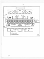
1
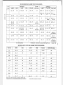
1990 DEALER SERVICE MANUAL UPDATE BULLETIN SUPPLEMENT FOR THE 1990 CHEVROLET LIGHT DUTY TRUCK UNIT REPAIR, ASTRO VAN, C-K PICKUP TRUCKS, R-V-G-P MODELS, AND S-10 MODELS SERVICE MANUALS ST-502-90SB 1990 SERVICE MANUAL SUPPLEMENT CAUTION To reduce the chance of personal injury and/or property damage the follow ing instructions must be carefully observed: Proper service and repair are important to the safety of the service technician and the safe, reliable operation o f all motor vehicles. If part replacement is necessary, the part must be replaced w ith one of the same part number or w ith an equivalent part. Do not use a replacement part of lesser quality. The service procedures recommended and described in this service manual are effective methods of performing service and repair. Some of these procedures require the use of tools specially designed for the purpose. Accordingly, anyone who intends to use a replacement part, service procedure or tool, which is not recom mended by the vehicle manufacturer, must first deter mine that neither his safety nor the safe operation of the vehicle w ill be jeopardized by the replacement part, ser vice procedure or tool selected. It is important to note that this manual contains various "C a u tio n s " and "N o tic e s " that m ust be carefully observed in order to reduce the risk of personal injury during service or repair, or the possibility that improper service or repair may damage the vehicle or render it unsafe. It is also important to understand that these "C autions" and "N o tice s" are not exhaustive, because it is impossible to warn of all the possible hazardous consequences that might result from failure to follow these instructions. This manual contains Dealer Service Update Bulletins covering service manual updates which were issued September 1989 through August 1990. Some pages may apply to prior or later model years. It will also be necessary to check bulletins issued after August 1990. Any reference to brand names in this manual is intended merely as an example of the types of lubricants, tools, and materials recommended for use. In all cases, an equivalent may be used. NOTICE: When fasteners are rem oved, alw ays rein stall them at the same location from w hich they w ere removed. If a fastener needs to be replaced, use the correct part n um ber fastener fo r th a t application. If the correct part n um ber fastener is not available, a fastener o f equal size and strength (or stronger) m ay be used. Fasteners th a t are not reused, and those requiring thread locking com pound w ill be called out. The correct torque value m ust be used w hen in sta ll ing fasteners that require it. If the above co nd itio ns are not follow ed, parts o r system dam age could result. CHEVROLET MOTOR DIVISION General Motors Corporation WARREN, MICHIGAN © 1991 GENERAL MOTORS CORPORATION No part o f fo rm or by otherwise, Corp. This ALL RIGHTS RESERVED • LITHO IN U.S.A. this publication m ay be reproduced, stored in any retrieval system or transm itted, in any any means, including but not lim ited to electronic, m echanical, photocopying, recording or w ith o u t the p rior w ritten perm ission o f the Chevrolet M o to r Division o f General M otors includes all text, illustrations, tables and charts. Table of Contents Sec t io n B u l le t i n Nunbers 3E 5 5 6C 6E 7A 90 -1 0 6 -3E 9 0 -2 1 3 -5 9 0 -2 6 9 -S 9 0 -2 0 6 -6C 9 0 -1 9 9 -6E 9 0 -7 7 -7 A 7A BO 9Q-89-7A 9 0 -5 6 -8 S u b je c t Wheel Alignm ent S p e c ific a tio n s 4UAL B rake B leedin g Procedure RUAL Brakes C o n tro lle d I d l e Speed Updated Chart R evised C hart C-1D, Coda 3 3 , 3 4 , 6 3 , 64 R evised P r e lim in a r y Check Procedure and S h if t Speed C h art f o r 4 L60/700-R 4 Transm issions Revised Accum ulator S p rin g Chart Packard 32 Way Connector I d e n t i f i c a t i o n gen CHEVROLET MOTOR DIVISION CHEVROLET General Motors Corporation Service D epartm ent i Subject: SERVICE Chevrolet Dealer Service Update Bulletin 90-106-3 E Number: 3E Section: December 1989 Dale: 993101 Corporate Bulletin N o .: WHEEL ALIGNMENT SPECIFICATIONS mom andvear: 1990 PASSENGER CARS AND LIGHT DUTY TRUCKS ATTACHED FOR YOUR INFORMATION ARE THE 1990 MODEL WHEEL ALIGNMENT SPECIFICATIONS FOR ALL GM PASSENGER CARS AND LIGHT TRUCKS. Chevrolet bulletins are intended for use by professional technicians, NOT a “do-it-yourselfer." They are written to inform these technicians of conditions that may occur on some vehicles, or to provide information that could assist in the proper service of a vehicle. Properly trained technicians have the equipment, tools, safety instructions, and know-how to do a job properly and safely. If a condition is described, DO NOT assume that the bulletin applies to your vehicle, or that your vehicle will have that condition. See your Chevrolet dealer for information on whether your vehicle may benefit from that information. GSD 148D Rev. 8/86 UPDATE COPYRIGHT 1989 CHEVROLET MOTOR DIVISION GENERAL MOTORS CORPORATION ALL RIGHTS RESERVED SERVICE TO: ALL CHEVROLET DEALERS 1990 GM PASSENGER CAR ALIGNMENT SPECIFICATIONS (DEGREES) FRONT WHEELS CASTER CAH UNE CAMBER CROSS A 0 00+ /- .50 0 .70 ▲ 1 .7 0 + / -0 70 CROSS TOTAL TOE STEERING WHEEL ANGLE 0 .70 0.00 +/- ,20 +/- 3.5 REAR WHEELS TOTAL TOE CAMBER THRUST ANGLE 90-106-3E ▲ 0 0 0 ♦/- .30 A 0 00 +/- 30 A 0 0 0 + / - 15 ▲ 0 0 0 +/- .50 A +0.20 +y- 20 A 0 .00+/• 15 A 0.00 +/- 30 (ref. only) A 0 0 0 + / -. 15 (ret only) A 0 00 +/- 35 A A B +0 80 +/- 80 1.00 2 80 +/- 1 00 1.00 +0 10+ /- .20 +/- 2 5 F +0 30 +/- .50 0 .70 4 80 +/- 0 50 0 .7 0 0.00 +/- .20 +/- 3.5 L ♦0 60 +/- .60 -0 20 +/- .60 1 00 1.00 ▲ 1 .1 5 + / -0 75 0 70 0 00 +/- .20 +/- 3 5 T O C O LU M N ▲ -0.25 +/- 50 A +0 30 +/- .25 J/N 0.00 +/- .70 1.00 A 1.7 0 + / - 1 00 0 70 0.00+ /- 20 +/- 5.0 ▲ -0.25 +/- .50 A +0.25+/- .16 W + 0 .70 +/- .50 0 75 ▲ 2.00 +/- 0.50 ▲ 1 3 0 + /-0 .5 0 0 .75 0 .75 0 00 +/- .20 +/- 3.5 TO C O LU M N A +0 .1 0 + / -.5 0 A -0 15 W- .50 A -0 .10 V - .30 A Y +0 50+ /- 50 1.00 5 80 +/- 0 80 1.00 0 00 +/- .20 +/- 2 0 +0 20 +/- .50 +0.20 +/- .20 0 0 0 W - .15 REC O M M EN D ED S -0.25 +/- .7 5 1.50 0 9 0 + / -0 75 1 50 +0 08 +/- .31 +/- 5.0 -0.50 +/- .7 5 +0.S0 +/- .31 0 0 0 + /- 15 REC O M M EN D ED M/R +0.31 +/- 1.0 0 1.00 2.25 +/- 0 50 1 00 0 00 +/- 34 +/- 5 0 0.00 +/- .7 5 +0 43 +/- .43 0 .0 0 +/- .1 5 R EC O M M EN D ED NOTE: A NOT ADJUSTABLE Tlr*-Whe«l Systems ▲ A General Motors Proving Ground Milford, Micnigan 48042-2001 A 0 0 0 + /- .1 5 November 17,1989 1990 GENERAL MOTORS TRUCK WHEEL ALIGNMENT SPECIFICATIONS (DEGREES) TRUCK UNE CAMBER CROSS CASTER CROSS TOTAL TOE STEERING WHEEL ANGLE C -K +.50 ± 50 1 00 3 .7 5 ± 1.00 1.0 0 + .2 4 ± .20 ± 5 .0 G-10/20 +.50 ± .75 1.00 i 1.00 1.0 0 0 ± 20 ±5 0 0 ± 20 ±50 G -3 0 +.25 ± .75 M + 80 ± 80 1 00 2.60 ± 1.00 1.0 0 L A L L WO + .91 ± .80 1 00 3.52 ± 1.00 1.0 0 1 .50 1.00 1 .7 0 ± 1.00 + .25 ± .75 1.00 S -T + eo± R -10 + .7 0 ± 7 5 R-20/30 + 25 ± 75 V ALL 1 50 ± 75 U P 00 bo t .20 ±50 19 0 .00 ± 2 0 ± 5 .0 ± 1.00 1.0 0 +.34 ± 23 ±50 1 00 1 80 ± 1.00 1.00 +.30 ± .20 ± 5 .0 1 00 ± 1.00 1.00 + 15 ± 23 ±50 t 1 00 0. ± .23 ±50 1 00 8 00 10 0 N O IE S ■ACTUAL -C O R REC TED1 C A S IE R A N G L E « A l IG NER A N G IE . FRAME RAIL A N G IE (FRAME ANGLE :s NEGATIVE WHEN LOWER IN REAR. ANO POSITIVE WHEN LOWE R IN FRONT.) V VEHICLE CASTER AND CAMBER ARE NOT ADJUSTABLE -.1 0 CHEVROLET CHEVROLET MOTOR DIVISION GS© Qensrtl Motors Corporation Technical Service Department Dealer Service Update Bulletin 90-213-5 Number; 5 Section: April 1990 Data: 065001 Subject: 4WAL BRAKE BLEEDING PROCEDURE Model and Year: Corporate Bulletin No.: 1990 M/L TRUCK This bleed procedure revises the bleed procedure published in the 1990 Light Duty Truck Service Manual Section 5 (reference Dealer Service Bulletin No. 90-65*5). This procedure is correctly listed in the 1991 S/T service manual as it applies to that model. Please place a copy of this bulletin in the 1990 Light Duty Truck Service Manual. SERVICE TO: ALL CHEVROLET DEALERS The following brake bleeding procedure is to be used on ALL 1990 M/L Vans equipped with 4 wheel anti-lock brake systems. 4WAL Brake System Bleeding Procedure: 1. Assure ignition is in off position. 2. Deplete brake booster by pumping the brake pedal several times. 3. Assure the master cylinder is full. 4. Install two J 35856 bleed valve tools on the 4WAL EHCU at the high pressure accumulators (HPA) (see Figure 2). 5. Install one J 35856 bleed valve tool on the combination valve. 6. There are internal bleed screws on each side of the EHCU module (Figure 2). The bleed screws are used to open the internal passages within the EHCU module. Back off the two internal bleed screws 1/4 to 1/2 turn. 7. Use conventional bleeding process; Pressure, Vacuum or Pedal Bleeding. Chevrolet bulletins are intended for use by professional technicians, NOT a "do-ji-yom-selfar-" They are written to inform these technicians of conditions that may occur on some vehicles, or to provide information that could assist in the proper service of a vehicle. Properly trained technicians have the equipment, tools, safety instructions, and know-how to do a job properly and safely. K a condition is described, DO NOT assume that the bulletin appl ies to your veh icle, or that your vehicle will have that condition. See your Chevrolet dealer for information on whether your vehicle may benefit from that information. QSD14SJ Rav. 12/89 UPDATE IMPORTANT: The ignition switch must be off through-out bleeding or false trouble codes could be set to memory. -2 - 1MP0RTANT: The EHCU module should be bled after replacement or if trapped air is thought to be in the unit. It should not be necessary to bleed the EHCU module if the fluid has not become contaminated or if no air is thought to be in the module. In the event the EHCU module needs to be bled the module should be thoroughly bled BEFORE the wheel cylinders and calipers. There are two bleeders on the front of the unit that look like normal brake bleeders (Figure 2). These are the modulator bleeders for bleeding the EHCU module and they must remain closed when the unit is not pressur ized. 8. EHCU Module Bleed Procedure (if required). Pedal bleeding method described below: » Slowly depress the brake pedal one time and hold. • Open one of the modulator bleeders on the front of the unit until fluid flows clearly or pedal is depressed. • Close the modulator bleeder and tighten to 7 Nm. (60 in.lbs). DO NOT OVER TIGHTENI • Slowly release the pedal. • Wait 15 seconds, then repeat the above sequence, including the 15 second wait until all air is purged from the EHCU module. Repeat the above process on the remaining modulator bleeder on the front of the EHCU module until all air is purged from the unit. 9. Always maintain a full master cylinder. 10. Bleed wheel cylinders and calipers as described in HYDRAULIC BRAKES (Sec. 5A of the service manual). 11. Remove the three J 35856 bleed valve tools. 12. Close the left internal bleed screw and tighten to 7 Nm (60 in.lbs.). DO NOT OVER TIGHTEN! 13. Close the right internal bleed screws and tighten to 7 Nm (60 in.lbs). DO NOT OVER TIGHTEN! 14. Start vehicle and evaluate the brake pedal feel. If firm, continue with this procedure. If the pedal is soft or spongy, reinstall tools and re-bleed the system starting with step 1. Any RE-BLEED due to soft or spongy pedal should always include bleeding the EHCU module (step 9). 90-213-5 -3 15. Perform 3 function tests using the Tech-1 Function test procedure. 16. Road test vehicle. IMPORTANT: Failure to follow this procedure accurately may result in an immediate soft pedal after the first anti-lock stop and technician induced stored codes. COPYRIGHT 1990 CHEVROLET MOTOR DIVISION GENERAL MOTORS CORPORATION ALL RIGHTS RESERVED 90-213-5 -4 - Figure 1 4WAL EHCU Assembly Mounting—M/L Series Internal Bleed Screw (Left Side of EHCU. Right Side Opposite) Modulator Bleeders EHCU Module HPA Pins Figure 2 4WAL EHCU Service Bleed Valves 90-213-5 CHEVROLET CHEVROLET MOTOR DIVISION Dealer Service Update Bulletin G 0 © General Motors Corporation Technical Service Department 90-269-5 Number: 5 Section: July 1990 Date: 065008 Corporate Bulletin No.: Subject: RWAL BRAKES Model and Year: 1988-90 C/K AND 1989-90 S/T/M AND 1990 R/V AND G TRUCKS The attached chart (see Figure 1) is a revised code 5 diagnostic chart. The revised chart requires a check of wiring and the transfer case switch operation before the control valve is replaced on 4-wheel drive vehicles. The chart also revises code 5 diagnostic information in the following service manuals: C/K C/K C/K R/V AND G S/T S/T M VAN M VAN UPDATE 1988 1989 1990 1990 1989 1990 1989 1990 SERVICE TO: ALL CHEVROLET DEALERS COPYRIGHT 1990 CHEVROLET MOTOR DIVISION GENERAL MOTORS CORPORATION ALL RIGHTS RESERVED Chevrolet bulletins are intended for use by professional technicians, NOT a “do-it-yourselfer." They are written to inform these technicians of conditions that may occur on some vehicles, or to provide information that could assist in the proper service of a vehicle. Properly trained technicians have the equipment, tools, safety instructions, and know-how to do a job properly and safely. If a condition is described, DO NOT assume that the bulletin applies to your vehicle, or that your vehicle will have that condition. See your Chevrolet dealer for information on whether your vehicle may benefit from that information. GSD148J Rev. 12/B9 -2 - CODE 5 EXCESSIVE ACTUATIONS OF THE DUMP VALVE DURING AN ANTILOCK STOP r * IGNITION “ON" • GROUND THE DIAGNOSTIC TERMINAL _(FROM DIAGNOSTIC CIRCUIT CHEC [ BRAKE LIGHT FLASHES CODE 5 1 -------------- GROUND — —1 .r ---- ------------- 1------1 o v_ " I IGNITION "OFF" o A H 1 IS THE VEHICLE EQUIPPED WITH 4WD? > ALDL CONNECTOR (DIAGNOSTIC TERMINAL) YES | NO ENGAGE 4WD REPLACE THE VALVE ASSEMBLY. REFER TO ISOLATION/DUMP VALVE IN THIS SECTION. i .....T 4WD INDICATOR "ON" ~ VERIFY OPERATION OF THE REAR BRAKES. REPAIR IF NECESSARY YES NO CHECK VOLTAGE AT BRAKE LAMP SWITCH TERMINAL A WITH THE BRAKES APPLIED (CKT 420) REPAIR. REFER TO TRANSFER CASE 0 VOLTS j 12 VOLTS CHECK VOLTAGE AT SINGLE CAVITY CONNECTOR FROM TRANSFER CASE SWITCH CHECK VOLTAGE AT PIN F OF THE MODULE CONNECTOR (CKT 420) 12 VOLTS | 0 VOLTS | 0 VOLTS | REPAIR WIRING REPLACE TRANSFER CASE SWITCH IGNITION “OFF" • REMOVE THE STOP/HAZARD FUSE* • INSTALL THE FUSE AFTER 5 SECONDS ■ECM B fuse on S/T-Series truck. Stop/hazard fuse on C/K- and FW-Series truck. Hom/dome fuse on M-Series truck. Tail LPS fuse on G-Senes truck. PERFORM THE DIAGNOSTIC CIRCUIT CHECK Figure 1 90*269-5 12 VOLTS I REPAIR WIRING O CHEVROLET CHEVROLET MOTOR DIVISION G S © Number: 6C S e fV iC e General Motors Corporation Technical Service Department Subject: 90-206-6C Dealer Section: U 0 0 3 1 0 April 1990 Bulletin Date: 036504 Corporate Bulletin No.: CONTROLLED IDLE SPEED UPDATED CHART Model and Year: 1990 ALL TRUCKS (EXCEPT TRACKER) This bulletin updates the chart shown on Page 4-43 in the Fuel Control Section of the 1990 Shop Manual. This information is for all 1990 Light-duty trucks (except Tracker) with gas engines. 1990 CONTROLLED IDLE SPEED TRANS GEAR <D/N) IDLE SPEED (RPM) co unts; IAC OPEN/CLOSED LO O P- 2.5L MAN. AUTO. N D 950(S) 800(S) 750(M) 5-20 15-40 CLOSED CLOSED 2.8L MAN. N 800 5-20 OPEN 3.1 L AUTO. D 650 5-15 CLOSED 4.3L (under 8500 GVW) MAN. AUTO. AUTO.(1) MAN.(1) AUTO.(2) N D D N D 550 537 500 600 588 2-20 10-25 5-30 5-30 10-25 CLOSED CLOSED CLOSED CLOSED CLOSED 4.3L (over 8500 GVW) MAN. AUTO. N D 650 650 12-30 20-35 CLOSED CLOSED 5.0L MAN. AUTO. AUTO.(3) N D D 600 500 500 5-30 5-30 5-30 OPEN CLOSED CLOSED Chevrolet bulletins are intended for use by professional technicians, NOT a "do-it-yourselfer.* They are written to inform these technicians of conditions that may occur on some vehicles, or to provide information that could assist in the proper service of a vehicle. Properly trained technicians have the equipment, tools, safety instructions, and know-how to do a job properly and safely. If acondition is described, DO NOT assume that the bulletin applies to your vehicle, or that your vehicle will have that condition. See your Chevrolet dealerfor information on whether your vehicle may benefit from that information. QS0146J Rev. 12/89 UPDATE ENGINE SERVICE TO: ALL CHEVROLET DEALERS -2 - ENGINE TRANS MAN. 5.7L AUTO. (under 8500 GVW) MAN. 5.7L MAN.(4) (over 8500 GVW) AUTO. GEAR fD/Nl IDLE SPEED IAC COUNTS* (RPM) OPEN/CLOSED LQ.Q.P" N D 600 525 5-30 5-30 OPEN CLOSED N D 650 650 550 5-30 5-30 5-30 OPEN CLOSED*** CLOSED 7.4L (under 8500 GVW) MAN. AUTO. N D 800 750 5-30 5-30 OPEN OPEN 7.4L (above 8500 GVW) MAN. AUTO. N D 750 750 5-30 5-30 OPEN OPEN * Add 2 counts for engines with less than 500 miles. Add 2 counts for every 1000 ft. above sea level (4.3L & V8). Add 1 count for every 1000 ft. above sea level (2.5L & 2.8L). ** Let engine idle until proper fuel control status (open/closed loop) is reached. *** Switches to open loop after 3 min. (1) 4.3L S/T-series. (2) 4.3L High-Output M/L-van series. (3) 3-Speed Automatic in a C10 pickup with Federal emissions and no A.I.R. system. (4) G-van or Suburban with a single catalytic converter. COPYRIGHT 1990 CHEVROLET MOTOR DIVISION GENERAL MOTORS CORPORATION ALL RIGHTS RESERVED 90-206-6C rO CHEVROLET Gp o CHEVROLET MOTOR DIVISION Dealer Service V J '— ^ _ 7 U 00816 General Motors Corporation T»cfinical Sarvk'.e Department ,, Bulletin Subiecs: REVISED CHART C-1D, CODE 33, 34, 63, 64 Mod* and Year: 90-199-6E Number: 6E SecBon: March 1990 Dai#: 016510 Corporal*BulletinNo.: 1980-90 PASSENGER CARS AND TRUCKS This bulletin revises the Manifold Absolute Pressure (MAP) Output Check Chart C-1D and updates Code 33, Code 34, Code 63, and Code 64 in the Service Manual section on “Driveability And Emissions" (Section 6E1, 6E2, and 6E3). This information applies to all MAP Sensors on 1980-1990 vehicles with gasoline engines (except turbocharged) with green (standard) MAP sensor electrical connector insert or the solid black MAP sensor electrical connector insert. UPDATE The revised chart and facing page information is as follows: - Diagnostic Chart C-1D and facing page. The updated - Diagnostic - Diagnostic - Diagnostic - Diagnostic SERVICE TO: ALL CHEVROLET DEALERS chart and facing page information is as follows: Chart Code 33 and facing page. Chart Code 34 and facing page. Chart Code 63 and facing page. Chart Code 64 and facing page. COPYRIGHT 1990 CHEVROLET MOTOR DIVISION GENERAL MOTORS CORPORATION ALL RIGHTS RESERVED Chevrolet bulletins are intended for use by professional technicians, NOT a “rin-rt-yourseifer.* They are written to inform these technicians of conditions that may occur on some vehicles, or to provide information that could assist in the proper service of a vehicle. Properly trained technicians have the equipment, tools, safety instructions, and know-how to do a job properly and safely. If acondition is described, DO NOT assume that the bulletin applies to your vehicle, or that your vehicle will have that condition. See your Chevrolet dealer for information on whether your vehicle may benefit from that information. GSD148J Rev. 12/89 DRIVEABIUTY AND EMISSIONS CHART C-1D MANIFOLD ABSOLUTE PRESSURE (MAP) VOLTAGE OUTPUT CHECK Circuit Description; The Manifold Absolute Pressure (M A P ) sensor measures the changes in the intake manifold pressure which result from engine load (intake manifold vacuum) and rpm changes; and converts these into a voltage output. The ECM sends a 5 volt reference voltage to the M AP sensor. As the manifold pressure changed, the output voltage o f the sensor also changes. By monitoring the sensor output voltage, the ECM knows the manifold pressure. A lower pressure (low voltage) output voltage will be about 1 - 2 volts at idle. W hile higher pressure (high voltage) output voltage will be about 4 - 4.8 at Wide Open Throttle (W OT). The M A P sensor is also used, under certain conditions, to measure barometric pressure, allowing the ECM to make adjustments for different altitudes. The ECM uses the M A P sensor to control fuel delivery and ignition timing. Test Description: Numbers below refer to circled numbers on the diagnostic chart. 9 • 1. 2. 3. Check vacuum hose to sensor for lea k in g or restriction. Be sure that no other vacuum devices are connected to the M A P hose. Important Be sure to use the sam e D ia g n o s tic T e s t Equipment for all measurements. When comparing "Scan” readings to a known good vehicle, it is important to compare vehicles that use a M AP sensor having the same color insert or having the same "H ot Stamped” number. See figures on facing page. Applying 34 kPa (10” H g) vacuum to the M AP sensor should cause the v o lta g e to change. Subtract second reading from the first. Voltage value should be greater than 1.5 volts. Upon applying vacuum to the sensor, the change in voltage should be instantaneous. A slow voltage change indicates a faulty sensor. 90-199-6E NOTE: 4. Make sure electrical connector remains securely fastened. Disconnect sensor from bracket and twist sensor by hand (o n ly ) to ch eck fo r in t e r m it t e n t connection. Output changes greater than . 1 volt indicate a bad connector or connection If O K , replace sensor. -3 DRIVEABILITY AND EMISSIONS CHART C-1D MANIFOLD ABSOLUTE PRESSURE (MAP) VOLTAGE OUTPUT CHECK NOTE: © THIS CHART ONLY APPLIES TO MAP SENSORS HAVING GREEN OR BLACK COLOR KEY INSERT (SEE BELOW). • IGNITION "ON." ENGINE "OFF." • "SCAN" TOOL SHOULD INDICATE A MAP SENSOR VOLTAGE. • • COMPARE THIS READING WITH THE READING OF A KNOWN GOOD VEHICLE. SEE FACING PAGE TEST DESCRIPTION, STEP 1. VOLTAGE READING SHOULD BE WITHIN, t .4 VOLT. IS IT? 1 YES © NO JZ • • • • • DISCONNECT AND PLUG VACUUM SOURCE TO MAP SENSOR. CONNECT A HAND VACUUM PUMP TO MAP SENSOR. START ENGINE. NOTE MAP SENSOR VOLTAGE. APPLY 34 kPa (10“ Hg)OF VACUUM AND NOTE VOLTAGE CHANGE. SUBTRACT SECOND READING FROM THE FIRST. VOLTAGE VALUE SHOULD BE GREATER THAN 1.5 VOLTS. IS IT? REPLACE SENSOR. NO YES © NO TROUBLE FOUND. CHECK SENSOR VACUUM SOURCE FOR LEAKAGE OR RESTRICTION. BE SURE THIS 50URCE SUPPUES VACUUM TO MAP SENSOR ONLY. © JZ CHECK SENSOR CONNECTION. IF OK, REPLACE SENSOR. 12-14-89 LS 904S-6E LS 8963-6E Figure 1 - Color Key Insert Figure 2 - Hot-Stamped Number CLEAR CODES AND CONFIRM "CLOSED LOOP" OPERATION AND NO "SERVICE ENGINE SOON* LIGHT. 90-199-6E 2-28-90 • 7S3162-6E -4 - DRIVEABILITY AND EMISSIONS ! « I I CODE 33 MANIFOLD ABSOLUTE PRESSURE (MAP) OUTPUT CHECK (SIGNAL VOLTAGE HIGH - LOW VACUUM) Circuit Description: The Manifold Absolute Pressure (M A P) sensor responds to changes in manifold pressure (vacuum). The ECM receives this information as a signal voltage that w ill vary from about 1 to 1.5 volts at closed throttle (idle) to 4.5 - 4.8 volts at wide open throttle (low vacuum). I f the M AP sensor fails, the ECM will substitute a fixed M A P value and use the Throttle Position Sensor (TPS) to control fuel delivery. Test Description: Numbers below refer to circled numbers on the diagnostic chart. 1. This step will determine if Code 33 is the result o f a hard failure or an intermittent condition. A Code 33 will set under the following conditions: • M A P signal voltage is too high (low vacuum). • TPS less than 2 % . • These conditions exist longer than 5 seconds. 2. This step simulates conditions for a Code 34. If the ECM recognizes the change, the ECM and C K T 416 and C K T 432 are OK. If C K T 469 is open, there may also be a stored Code 23. Diagnostic Aids: W ith the ignition "O N ” and the engine stopped, the manifold pressure is equal to atmospheric pressure and the signal voltage will be high. This information is used by the ECM as an indication o f vehicle altitude. Comparison o f this reading with a known good vehicle with the same sensor is a good way to check accuracy of a "suspect” sensor. Readings should be the same ± .4 volt. 90-199-66 A Code 33 will result if C K T 469 is open or if C K T 432 is shorted to voltage or to C K T 416. If Code 33 is intermittent, refer to Section "B ” . NOTE: • • • M a k e sure e l e c t r i c a l c o n n e c t o r remains securely fastened. Check all connections. Disconnect sensor from bracket and twist sensor by hand (only) to check for intermittent connections. Output changes greater than .1 volt indicates a bad connector or connection. If OK, replace sensor. Refer to C H A R T C-1D, M A P sensor voltage output check for further diagnosis. > V -5 - DRIVEABILITY AND EMISSIONS CODE 33 MANIFOLD ABSOLUTE PRESSURE (MAP) SENSOR CIRCUIT (SIGNAL VOLTAGE HIGH - LOW VACUUM) 10-26-89 • 7S 3 2 1 0-6E 90-199-6E -6 - DRIVEABILITY AND EMISSIONS MANIFOLD ABSOLUTE PRESSURE (VACUUM) CODE 34 MANIFOLD ABSOLUTE PRESSURE (MAP) SENSOR CIRCUIT (SIGNAL VOLTAGE LOW - HIGH VACUUM) Circuit Description: The Manifold Absolute Pressure (M AP) sensor responds to changes in manifold pressure (vacuum). The ECM receives this information as a signal voltage that w ill vary from about 1 to 1.5 volts at closed throttle (idle) to 4.5 - 4.8 volts at wide open throttle (low vacuum). i f the M A P sensor fails, the ECM will substitute a fixed M A P value and use the Throttle Position Sensor (TPS ) to control fuel delivery. Test Description: Numbers below refer to circled numbers on the diagnostic chart. 1. This step determines i f Code 34 is the result o f a hard failure or an intermittent condition. A Code 24 will set when M A P signal voltage is too low and the ignition is "O N .” 2. Jumpering harness terminals "B ” to "C " (5 volts to signal circuit) w ill determine if the sensor is at fault, or if there is a problem with the ECM or wiring. 3. The "Scan” tool may not display 5 volts. The important thing is that the ECM recognizes the voltage as more than 4 volts, indicating that the ECM and C K T 432 are OK. Comparison o f this reading with a known good vehicle with the same sensor is a good way to check accuracy o f a "suspect” sensor. Readings should be the same ± .4 volts. Also C H A R T C-1D can be used to test the M A P sensor. Refer to "Intermittents” in Section "B ” . NOTE: • • Diagnostic Aids: • An interm ittent open in C K T 432 or C K T 416 will result in a Code 34. W ith the ignition "O N ” and the engine "O F F ,” the m anifold pressure is equal to atmospheric pressure and the signal voltage w ill be high. This information is used by the ECM as an indication o f vehicle altitude. 90-199-6E M a k e su re e le c t r ic a l c o n n e c to r remains securely fastened. Check all connections. Disconnect sensor from bracket and tw ist sensor By hand (only) to check for intermittent connections. Output changes greater than .1 volt indicates a bad connector or connection If O K, replace sensor. Refer to C H A R T C-1D, M A P sensor voltage output check for further diagnosis. -7 DRIVEA8ILITY AND EMISSIONS CODE 34 MANIFOLD ABSOLUTE PRESSURE (MAP) SENSOR CIRCUIT (SIGNAL VOLTAGE LOW - HIGH VACUUM) 10-29-89 • 7S 3211 -61 90-199-6E - 8 - DRIVEABILITY AND EMISSIONS CODE 63 MANIFOLD ABSOLUTE PRESSURE (MAP) SENSOR CIRCUIT (SIGNAL VOLTAGE HIGH - LOW VACUUM) Circuit Description: The Manifold Absolute Pressure (M A P ) sensor responds to changes in manifold pressure (vacuum). The ECM receives this information as a signal voltage that will vary from about 1 to 1.5 volts at closed throttle (idle) to 4.5 - 4.8 volts at wide open throttle (low vacuum). If the M AP sensor fails, the ECM will substitute a fixed M A P value and use the Throttle Position Sensor (TPS) to control fuel delivery. Test Description: Numbers below refer to circled numbers on the diagnostic chart. 1. Code 63 will set when: • Engine running. • Manifold pressure greater than 75.3 kPa (A/C "O F F ” ) 81.2 kPa (A/C "O N"), • Throttle angle less than 2%. • Conditions met for 2 seconds. Engine misfire or a low unstable idle may set Code 63. 2. W ith the M A P sensor disconnected, the ECM should see a low voltage if the ECM and wiring are OK. Diagnostic Aids: With the ignition "O N ” and the engine stopped, the manifold pressure is equal to atmospheric pressure and the signal voltage will be high. This information is used by the ECM as an indication o f vehicle altitude. Comparison of this reading with a known good vehicle with the same sensor is a good way to check accuracy o f a "suspect” sensor. Readings should be the same ± .4 volt. I f idle is rough or unstable, refer to symptoms in Section "B ” for items which can cause an unstable idle. An open in C K T 455 or the connection will result in a Code 63. NOTE: • • • 90-199-6E M a k e su re e le c t r ic a l c o n n e c to r remains securely fastened. Check all connections. Disconnect sensor from bracket and tw ist sensor by hand (only) to check for intermittent connections. Output changes greater than .1 volt indicates a bad connector or connection. If O K, replace sensor. Refer to C H A R T C-1D, M AP sensor voltage output check for further diagnosis. -9 DRIVEABILITY ANO EMISSIONS CODE 63 MANIFOLD ABSOLUTE PRESSURE (MAP) SENSOR CIRCUIT (SIGNAL VOLTAGE HIGH - LOW VACUUM) 2 23 -9 0 ?S 3 1 5 7 -6 E 90-199-6E - 10 - DRIVEABILITY AND EMISSIONS CODE 64 MANIFOLD ABSOLUTE PRESSURE (MAP) SENSOR CIRCUIT (SIGNAL VOLTAGE LOW - HIGH VACUUM) Circuit Description: The Manifold Absolute Pressure (M A P) sensor responds to changes in manifold pressure (vacuum). The ECM receives this information as a signal voltage that will vary from about 1 to 1.5 volts at closed throttle (idle) to 4.5 - 4.B volts at wide open throttle (low vacuum). I f the M A P sensor fails, the ECM will substitute a fixed M A P value and use the Throttle Position Sensor (TPS ) to control fuel delivery. Test Description: Numbers below refer to circled numbers on the diagnostic chart. 1. Code 64 will set if: • Engine rpm less than 600. • Manifold pressure reading less than 13 kPa. • Conditions met for 1 second, or • Engine rpm greater than 600. • Throttle angle over 20%. • Manifold pressure less than 13 kPa. • Conditions met for 1 second. 2. This test to see if the sensor is at fault for the low voltage, or if there is an ECM or wiring problem. 3. This simulates a high signal voltage to check for an open in C K T 432. If the test light is bright during this test, C K T 432 is probably shorted to ground, If "Scan" reads over 4 volts at this test, C K T 474 can be checked by measuring the voltage at terminal "C ” (should be 5 volts). Diagnostic Aids: An intermittent open in C K T s 432 or 474 will result in a Code 64. With the ignition "O N ” and the engine "O FF,” the manifold pressure is equal to atmospheric pressure and the signal voltage will be high. This information is used by the ECM as an indication o f vehicle altitude. Comparison of this reading with a known good vehicle with the same sensor is a good way to check accuracy o f a "suspect” sensor. Readings should be the same ± .4 volts. Also C H A R T C-l D can be used to test the M A P sensor. Refer to "Interm ittents” in Section "B " NOTE: * * * 90-199-6E M ak e su re e le c t r ic a l c o n n e c to r remains securely fastened. Check all connections. Disconnect sensor from bracket and tw ist sensor By hand (only) to check for intermittent connections. Output changes greater than I volt indicates a bad connector or connection. If OK, replace sensor. Refer to C H A R T C -lD , M AP sensor voltage output check for further diagnosis. 11 - DRIVEABILITY AND EMISSIONS CODE 64 MANIFOLD ABSOLUTE PRESSURE (MAP) SENSOR CIRCUIT (SIGNAL VOLTAGE LOW - HIGH VACUUM) 3-S-90 7S3158-6E 90-199-6E CHEVROLET MOTOR DIVISION General Motors Corporation Service Department I Subject: SERVICE j Chevrolet Dealer Service Update Bulletin 90-77-7A Number 7A Section: October 1989 Date: 977145 Corporate Bulletin No.: REVISED PRELIMINARY CHECK PROCEDURE AND SHIFT SPEED CHART FOR 1990 4L60/700-R4 TRANSMISSIONS Model and Year: 1990 PASSENGER CARS WITH 4L60 TRANSMISSION 1990 LIGHT DUTY TRUCKS WITH 4L60 TRANSMISSION TO: ALL CHEVROLET DEALERS Chevrolet bulletins are intended for use by professional technicians, NOT a “do-it-yourselfer.” They are written to inform these technicians of conditions that may occur on some vehicles, or to provide information that could assist in the proper service of a vehicle. Properly trained technicians have the equipment, tools, safety instructions, and know-how to do a job properly and safely. If a condition is described, DO NOT assume that the bulletin applies to your vehicle, or that your vehicle will have that condition. See your Chevrolet dealer for information on whether your vehicle may benefit from that information. GSD 1400 Rev. 8/86 UPDATE COPYRIGHT 1989 CHEVROLET MOTOR DIVISION GENERAL MOTORS CORPORATION ALL RIGHTS RESERVED SERVICE This bulletin provides a revised Preliminary Check Procedure and Shift Speed Chart for 1990 HM4L60/700-R4 transmissions. These charts have been updated since publication of the 1990 Service Manuals. Please make reference to these changes in your service manuals. -2 - 1990 HYDRA-MATIC 4L60 SHIFT SPEED CHART MOOEl 12 MIN THROTTLE 2 3 MIM THROTTLE 34 MIN THROTTLE 12 W.O.T. 4-3 COAST DOWN 3 2 COAS DOWN 2 1 COAST DOWN BAM 8PM 13-16 14-18 22-27 26-31 50 + 40-52 29-43 31-48 36-48 29-33 13-20 17-24 9-11 10-12 CAM. CBM, KAM, MJM. MNM, WAM CCM. C fM , KBM, WBM CHM, CJM, KCM, RAM. WCM 14-18 16-19 24-42 25-31 49 + 50 + 11-14 12-14 22-28 46-53 37-48 37-47 34-45 15-24 14-24 14-17 31-43 33-46 29-41 15-21 10-13 DBM 14-18 27-31 38-51 31-43 28-33 16-24 9-12 FBM FTM FUM 14-18 12-15 26-33 22-25 22-25 42-53 40-49 39-47 37-51 28-41 25-41 16-24 13-22 14-21 24-31 44-52 36-46 28-35 31-39 25-31 3 4 -3 9 ^ 10-19 10-12 10-12 9-1 1 10-12 F2M 12-15 12-16 HBM, HHM HCM, HOM HJM 12-16 15-18 14-17 21-25 25-28 27-31 40-48 40-48 51 + 31-45 30-44 26-35 28-34 31-47 15-22 19-29 16-27 9-12 12-15 11-13 LAM, LBM, LCM, LDM, LFM 12-14 21-26 45-51 24-33 28-38 14-21 7-9 MBM,SAM MSM 12-14 10-13 20-25 20-23 47-53 40-46 24-37 22-36 37-47 26-37 10-18 11-19 9-12 SHM, TLM 13-18 24-31 50 + 30-42 37-48 19-26 11 1 3 YDM 13-16 21-25 39-51 39-53 22-28 13-19 9-1 1 27-44 NOTES: 1. ALL SPEEDS INDICATED ARE IN MILES PER HOUR. CONVERSION TO km/h = MPH x 1.609. 2 SHIFT POINTS WILL VARY SLIGHTLY OUE TO ENGINE LOADS AND VEHICLE OPTIONS. 3. SPEEDS LISTED WITH + EXCEED 65 MPH. Figure 1 90-77-7A 7-9 LH0002 4t60 -3 - PRELIMINARY CHECK PROCEDURE • • • • • • CHECK TRANSM ISSIO N FLUID LEVEL CHECK AND AD JU S T T.V. CABLE CHECK OUTSIDE M A N U A L LINKAGE A N D CORRECT CHECK ENGINE TUNE INSTALL PRESSURE GAGE CONNECT TACHOMETER TO ENGINE • CHECK PRESSURE AS FOLLOWS: (A ) A j j ACH PRESSURE Minimum T.V. Una Pressure Check Set the T.V. cable to specification: and w ith the brakes applied, take the line pressure readings in the ranges and at the engine r.p.m . indicated in the chart below. Full T.V. Lins Pressure Check Full T.V. line pressure readings are obtained by tying or holding the T.V cable to the full extent of its travel; and w ith the brakes applied, take the line pressure readings in the ranges and at the engine r.p.m. indicated in the chart below. •NOTICE Total running time for this combination not to exceed 2 minutes. CAUTION Brakes must be applied at all times. 1990 HYDRA-MATIC 4L60 TRANSMISSION PRESSURES RANGE PARK, NEUTRAL, OVERDRIVE & MANUAL 3RD <3> 1000 RPM NORMAL PRESSURE AT MINIMUM T.V. kP* PSI NORMAL PRESSURE AT FULL T.V. kPi PSI 8AM, FTM 451-515 65-75 816-1016 118-147 BPM CAM, C8M. HCM. HOM, KAM. MJM, MNM. WAM 451-515 65-75 1025-1306 65-75 65-75 CHM. CJM, RAM, TMM. WCM DBM 451-515 483-622 65-75 70-90 851-1063 947-1185 914 1149 149-189 123-154 CCM, CFM. TNM, WBM 451-515 451-515 FBM FUM. FZM 451-515 65 75 451515 65-75 H8M, HHM 483-622 451-515 70-90 65-75 451-515 65 75 65 75 MODEL HJM. V0M LAM. L8M, LCM, LDM. LFM REVERSE ® 1000 RPM 863 1 170 128 170 9181146 1073 1354 133166 155196 1019-1347 11161430 899-1134 148-195 162 207 130164 70-90 845-1068 797-1079 123 155 116 157 969-1231 141179 MBM. SAM MSM 451-515 483-622 SHM. TLM BAM. FTM 451-515 742-847 65 75 108123 1342-1870 195242 BPM CAM. CBM, HCM, HOM, KAM, MJM. MNM. WAM 742-847 742-847 108-123 108-123 1686-2146 1400-1747 245 311 203 253 226-283 CCM, CFM, TNM. WBM 742-847 108-123 1556-1948 CHM, CJM, RAM, TMM, WCM 742-847 108-123 1503-1889 218 274 DBM FBM 793-1023 580-662 115-148 84-96 1451 1924 1 180-1472 210-279 171 214 FUM. FZM HBM, HHM 742-847 108-123 115-148 1763-2225 16762214 256 323 243 320 HJM. YDM 793-1023 742 847 265 340 74 1 845 108-123 107-123 1834-2351 LAM. LBM. LCM. LDM. LFM 1474 I860 MBM. SAM MSM 580662 84-96 1085-1372 214270 157199 793-1023 742-847 115-14-8 108-123 13111773 1593-2023 231 293 1127 1286 163-186 1127 1286 163 186 DBM, HBM, HHM, MSM 1205-1554 1AM, LBM. LCM. L0M, LFM 11911359 175-226 173-197 1205-1554 1191-1359 175 226 173 19? SHM, TLM MANUAL 2ND & MANUAL LO @ 1000 RPM 137172 133167 BAM. BPM, CAM, CBM. CCM. CFM, CHM. CJM. FBM. FTM, FUM. FZM. HCM. HOM. HJM, KAM, MBM, MJM. MNM. RAM. SAM, SHM, TLM, TMM. TNM, WAM. WBM, WCV. YDM 190 257 Line pressure is basically controlled by pum p output and th e pressure regulator valve. In addition, line pressure is boosted in Reverse, Second and Lo by th e reverse boost valve. Also, in th e N eutral. D rive, In te rm e d ia te and Reverse positions of th e selector lever, the line pressure should increase w ith th ro ttle opening because o f th e T.V. system . T he pressure is controlled by the T.V. cable, the th ro ttle lever and b racket assem bly and the T.V. link, as w ell as th e control valve assem bly. The main line pressure ta p plug is located on the le ft side o f the transm ission above the outside m anual lever. LHOOC3-4160-R2 Figure 2 90-77-7A Chevrolet Dealer Service Update Bulletin CHEVROLET MOTOR OIVISION General Motor* Corporation S#mlc« DtparUrM nl CHEVROLET I SERVICE ] Subject: REVISED ACCUMULATOR SPRING CHART Model and Year: 9 0 -8 9 -7 A Number 7A Section: November 1989 Oate: 977159 Corporate Bulletin No 1990 B, Y CARS AND C, K, G, L, M, R, S, T, V TRUCKS WITH 4L60/700R4 AUTOMATIC TRANSMISSION TO: ALL CHEVROLET DEALERS Use the following chart to update your 1990 HYDRA-MATIC 4L60 Unit Repair Service Manual Section, page 4160-50, Figure 110. SERVICE This bulletin covers revised 1-2 and 3-4 Accumulator Spring Chart. The new chart is applicable to all 1990 THM 700-R4/HYDRA-MATIC 4L60 transmissions. See Figure 1. UPDATE COPYRIGHT 1989 CHEVROLET MOTOR DIVISION GENERAL MOTORS CORPORATION ALL RIGHTS RESERVED Chevrolet bulletins are intended for use by professional technicians, NOT a “do-it-yourselfer," They are written to inform these technicians of conditions that may occur on some vehicles, or to provide information that could assist m trie proper service of a vehicle. Properly trained technicians have the equipment, tools, safety instructions, and know-how to do a job properly and safely. If a condition is described, DO NOT assume that the bulletin applies to your vehicle, or that your vehicle will have that condition. See your Chevrolet dealer for information on whether your vehicle may benefit from that information. GSO 143D Rev 8/86 -2 - 1390 MODELS 1 2 AC CU M U LATO R SPRING COLOR 3 4 ACCUM ULATOR SPRING COLOR CHM. CJM. KCM. HAM. WCM ORANGE. LT. GREEN. WHITE OR PLAIN yiOLET CAM. CBM, KAM. MJM. MNM. WAM ORANGE. LT. GREEN. WHITE OR PLAIN OK. GREEN CCM. CFM. FTM. KBM. LAM. IBM. LCM. LDM, IFM , WBM ORANGE. LT. GREEN. WHITE OR PLAIN RED YELLOW FUM YELLOW HCM. MBM. SAM YELLOW REO SHM. TIM OK. GREEN LT. BLUE BAM. FZM YELLOW VIOLET HBM. HHM OK. GREEN YELLOW FBM. HDM OK. GREEN REO DBM ORANGE. LT. GREEN. WHITE OR PLAIN ORANGE. LT. GREEN. WHITE OR PLAIN HJM VIOLET YELLOW YOM YELLOW ORANGE. LT. GREEN. WHITE OR PLAIN MSM ORANGE. LT. GREEN. WHITE OR PLAIN YELLOW BPM, 1 88M OK. GREEN ORANGE, LT. GREEN, WHITE OR PLAIN LM 0 18 B -4 I8 0 -R 1 F ig u re 1 90-89-7A Chevrolet Dealer Service Update Bulletin CHEVROLET MOTOR DIVISION General Motors Corporation $« rv lc* 0 «p*rtm «nt CHEVROLET I SERVICE 90-56-8 Number: 8 Section: September 1989 Oats: 916521R Corporate Bulletin No.: Subject: PACKARD 32 WAY CONNECTOR IDENTIFICATION Mode* and Year: 1980-90 A, B, F, G, J, L, W, Y CARS AND ALL TRUCKS WITH GMP4 ECM APPLICATIONS This bulletin serves to clarify the labeling of the Packard 32 way connectors used on the GMP4 under dash ECMs. Currently a common strain relief is used in both the C-D 32 pin and the E-F 32 pin connectors. To properly identify these connectors, the strain reliefs must be removed. Use the lettering on the connector as shown on the attached document. This updates any previous information released concerning identification that indicates any of these colors as being C & D connectors, found in the 6E and 8D Sections of the affected Service Manuals, COPYRIGHT 1989 CHEVROLET MOTOR DIVISION GENERAL MOTORS CORPORATION ALL RIGHTS RESERVED Chevrolet bulletins are intended for use by professional technicians, NOT a “do-it-yourselfer.” They are written to inform these technicians of conditions that may occur on some vehicles, or to provide information that could assist in the proper service of a vehicle. Properly trained technicians have the equipment, tools, safety instructions, and know-how to do a job properly and safely, if a condition is described, DO NOT assume that the bulletin applies to your vehicle, or that your vehicle will have that condition. See your Chevrolet dealer for information on whether your vehicle may benefit from that information. GSD 1480 Rev 8/86 UPDATE The colors used at this time for the 32 pin E-F connector are yellow, mint green or orange. SERVICE TO: ALL CHEVROLET DEALERS O c 16 O 1S 14 □ 0 13 12 = 11 10 0 9 8 7 □ O 6 5 4 CO 3 2 1 G il USE THESE , B Q B Q Q Q Q Q Q B Q Q B Q B d ^ ,LETTERS FOR PROPER IDENTIFICATION T ed © 16 0 ^n=n=rbn=rhri; lO 13 1* D 0 D ( ) STRAIN RELIEF [ 7 ] CONNECTOR END 90-56-a m fn = n = R = n d T = rb o 1J PED ^37- 7-20-89 9S 8141-6E CHEVROLET