1
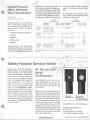
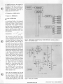
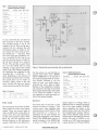
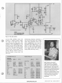
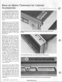
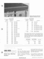
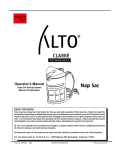
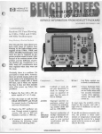
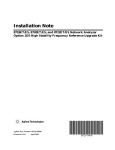
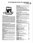
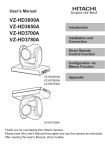
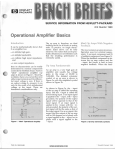
r
1
t
i
Communications
Nancy Thomas,
HP Stanford Park Diu.
Ask a service engineer or technician
what training they need and you’re
likely to hear, “We need measurement
and applications training.” If you
think about it, the request makes
sense. Understanding the environment that instruments operate in is
a valuable addition to one’s troubleshooting tool kit.
c
Hewlett-Packard has developed an
interactive training program aimed
at new technical entrants in the field
of digital microwave communications.
If you or your group is involved in
servicing microwave communications
equipment, you’ll want to order a
copy of the HP 11736A I-& Tutor, a
digital microwave communications
tool.
4
Structured Like a Laboratory
Workbench
-t
10;
t
’
I-& Tutor is educational software
r
with a manual, and is designed to be
used with the popular HP 9000 Model
216 or Model 236 computers. “I” and
“ Q stand for the in-phase and quadrature phase signals of complex phase
modulation used in today’s digital
microwave communications systems.
As shown in Figure 1, the program
is structured to model a complete
digital communications system, from
the analog signal input through modulation, transmission, demodulation,
and conversion back to analog. Figures 2-4 show working capabilities
of the program. Using your “measuring probe pointer” and handy set
of equipment displays, you can view
Pub. NO. 5952-0122
mum
t l
HP Digital Microwave Communications Guide
signals at various nodes of your system model in the time, frequency,
and vector domains.
Moves You Along the Learning
Curve Faster
You would probably have to read
several books and articles to get the
equivalent information presented in
WWW.HPARCHIVE.COM
one I-& Tutor package. There are no
heavy theoretical discussions or difficult mathematics involved. You
learn through a visual, intuitive approach. You look at actual signals at
places you select in the systems chain.
Then you can change the modulation
format, signal-to-noise ratio, or filter
alpha value, and compare the signals.
A series of lab exercises guide you to
@ Hewlett-Packard 1985
Real-world concerns
- Multipath fade
- High power amplifier
nonlinearities
- Advanced design mode
System Block
Diogrom:
Probe Pointer:
rn
Experimental exercise
- Probability of error [P(e)l vs.
SNR
- P(e) vs. filter bandwidth
- Multipath and “ M curves
- Distortion caused by HPA
nonlinearities
rn
Additional information
- Theory of I-&
modulation/demodulation
- Nyquist filters
- Bandwidth
System Signal
Displays;
Lab Notebook
Pages:
System
Porameters
and Key List
Modulation
Type‘OPSK
Filter Alpha’
SNR. 4068
3
l-qIflIJ.1
L
- FCC
Figure 1. 1-0 Tutor system overview. Using Hewlett-Packard’s 1-0 Tutor is like walking
through a complete digital microwave communications system with a handy set of test
equipment and displays.
explore the effects of degraded signalto-noise ratios, filter coefficient variations, and nonlinearities on system
error rates.
Even if you are only a casual computer user, you will quickly feel comfortable operating the program after
followingthe step-by-step instructions
in the manual. You can easily work
I-& Tutor into your busy schedule.
The entire program takes about eight
hours and can be spread over as
many sessions as you need.
Ordering Information
Subjects Covered Include:
rn
f-l
The HP Model number of I-& Tutor
is HP 11736A and the U.S. list price
is $95.00. You will need an HP 9000
Model 216A or Model 236A computer
with 640K bytes of memory, or the
Model 236C with 896K bytes. For
more information order flyer number
5954-6370 from your local HewlettPackard sales office listed in your
telephone white pages. 0
Understanding fundamental
concepts
- Phase and magnitude
- Practical digital modulation
techniques
- BPSK
- QPSK
- 16QAM
- Offset QPSK
- Offset 16QAM
- Understanding the system
block diagram
/7
Q
Clean and
tight crossover points
indicate errorfree transmission
Q or I
vs. time
eye diagram
/
/
\
Time
Clock Instant
Transition Period
Vector
Diagram
I
~T
*
*
I
*
I
Constellation
Diagram
.
’3
Figure 2. This is a constellation display.
You can examine the effects of system nonlinearities, such as amplitude compression
distortion, on the I and 0 vector diagrams.
2 BENCH BRIEFS JUNE/AUGUST 1985
Figure 3. Learn by exploring. You are able to change how the system operates and
immediately view the effects of those changes, such as degraded signal-to noise ratios
causing a closing of the “eye.”
WWW.HPARCHIVE.COM
Offers MiI Iimeter
wave Recalibration
Ed Cantrell,
HP Stanford Park Diu.
Hewlett-Packard can now offer precision recalibration services for our
new Q-band (33-50 GHz) and UBand (40-60 GHz) products,
including:
- Variable and fixed attenuators
- Couplers
- Detectors
-
calibration is directly traceable to
the National Bureau of Standards at
every standard frequency that NBS
maintains. At the other frequencies,
the calibration is indirectly traceable
to physical NBS standards; that is,
the reflection coefficient is indirectly
Estimated
Accuracy
U-band
(40 to 60 GHz)
Cal-factor
of power
sensor
3.9% RSS 40 GHz
(6.8% W.C. 40 GHz)
5.5% RSS 50 GHz
(9.3% W.C. 50 GHz)
Reflection
coefficient
0.004
Attenuation 0.04
No. of Price Estimated
Points (US. $) Accuracy
Directivity
of single
coupler
$1 50
+ 0.017rD
51
$100 0.004
+ 0.03/10 dB
51
Limited by measuring
system effective
directivity of 46 dB
51
$150 0.05
Per
attn.
setting
$300
No. of Price
Points (US.$)
Not currently
available
18
- Isolators
Service notes from HP relating to
personal safety and possible equipment damage are of vital importance to our customers. To make you
more aware of these important
notes, they are printed on paper
with a red border, and the service
suffix. In
note number has a “-S’
order to make you immediately
aware of any potential safety problems, we are highlighting safetyrelated service notes here with a
brief description of each problem.
Also, in order to draw your attention to safety-related service notes
on the service note order form at the
back of Bench Briefs, each appropriate number is highlighted by being
printed in color.
The following table provides a summary of HP’s current millimeter wave
calibration capabilites. 0
Q-band
(33 to 50 GHz)
Sliding shorts
You will receive a full report of the
calibration parameters as a function
of frequency, including uncertainties,
at every 1 GHz. HP millimeter wave
traceable to NBS through the diILLGL1sions of a sliding load and offset
short.
+ 0.02rD
51
$115
+ 0.03/10 dB
51
$175
Per
attn.
setting
51
$350
Limited by measuring
system effective
directivity of 46 dB
Note: Calibration factor, attenuation a n d directivity calibration reports also include reflection
coefficient.
Oscilloscopes -A mechanical hazard may exist on
these oscilloscopes. As you are carrying the unit, the strap handle may
break allowing the instrument to fall
on your foot.
Refer to the following photographs to
see if your oscilloscope requires modification. If your oscilloscope requires
the new large-headed handle retaining screws, you can order the following kit from Hewlett-Packard free of
charge. Note that the kit is available
at no charge until January 1, 1986.
Address your request for the kit to
the address listed below. Please indicate the instrument model and serial
number for all instruments requiring
this safety modification.
WWW.HPARCHIVE.COM
Old handle
fastener screw
New handle
fastener screw
HP P/N 00182-22401
Order HP Part No. 00812-69505from
HEWLETT-PACKARD CO.
P.O. Box 2197
Colorado Springs, CO 80901
Attn. Product Assurance Mgr.
JUNE/AUGUST 1985
0
BENCH BRIEFS 3
r.
Using Fiber Optics to Transmit a
Frequency Standard
I qL
Brett Frymire, NP OptoCommunications Diu.
Are you considering installing a frequency standard to all your repair
benches? You may want to think
about using fiber optic cable in place
of coax. Some of fiber optic's advantages are:
Transmitter HFBR-1402/4
The cable is smaller and easier to
handle than coax.
*."
Fiber optic cable
HFBR-3000
Does not g e n e r a t e electrical
interference.
rn
SMA connector
Receiver HFBR-2404
I t is not affected by electrical
interference.
Data security (cannot be easily
monitored).
Depending on the specific frequency
(for example, 10 MHz), fiber and coax
have similar electrical performance.
However, at higher frequencies, specifically 100 MHz, the fiber system
can transmit data over longer distances than can be done with a coax
system. Another factor that affects
performance is the environment in
which the system is located. An electrically noisy environment affects
coax but not fiber.
This is the proposed system that uses
fiber optic links. (A fiber optic link
consists of a transmitter, the fiber
cable, and the receiver, all of which
replaces the wire cable.) Again, there
are many different and possible variations of the same system. For example, if the distance between the
four benches and their corresponding
distribution amplifier is too far ( >5
meters), another entire fiber optic
link could be used to tie these benches
to their distribution amplifier. In any
case, this article describes the fiber
optic link shown in Figure 2.
,?
The criteria for our system is that it
must be able to operate from 1 MHz
I
This article will describe using fiber
optics to transmit frequency standards of 1 MHz, 5 MHz, and 10 MHz
with the standard HP components
shown i n the photograph. If your
system matches the example used in
this article, all that is required is to
build the circuits described and then
install the system. If you want to
make changes, the formulas, diagrams and schematics are supplied
that will allow you to build a custom
system for your office.
Before describing the fiber optic link,
let's look at a typical block diagram
of a system that uses coax (see Figure
1).Even if your system requirements
are slightly different, the basic idea
is the same. Now look at Figure 2.
4 BENCH BRIEFS JUNE/AUGUST 1985
7
Figure 1. Block diagram of typical frequency standard distribution scheme using coax.
WWW.HPARCHIVE.COM
and carry the signal for
tre distance (1meter to 1
). The Hewlett-Packard
;s that meet these requireinexpensive and easy to
d are listed below:
5
r
1
FREQUENCY
STANDARD
DISTRIBUTION
AMPLIFIER
I
1
I
I
itter-HFBR-1402/4
m
L‘
Receiver-HFBR-2404
RECEIVER
Cable-HFBR-3000
b
BENCH
As mentioned before, the proposed
system consists of three parts; the
transmitter, which is a light emitting
diode (LED) with support circuitry,
the fiber cable, which propagates the
light from the transmitter t o the
receiver, and the receiver, which is a
light sensitive photodiode with support circuitry.
Transmitter
!?
r
.
.
r
BENCH
I”
J
”
/
/
BENCH
3 I.
4.
The first part of the link, the transmitter, consists of a drive circuit that
current modulates the LED. The circuit shown in Figure 3 utilizes independent resistors (Rm and Rq) to
select the drive current for modulation (Ifm) and the quiescent current
for the dc current level of the LED
(Ifq). Note that the drive current sets
the amount of optical power that the
diode emits and that the LED should
operate from maximum peak current
to just above extinction (zero optical
power). Quiescent current refers to
the dc operating point that biases the
LED in the center of its operating
range (just like a transistor’s Q point).
Note the network of the three diodes
(CR1-3)and the 2N2905 (Ql) transistor. This network sets the voltage at
the LED to the center of the range
between Vcc and ground. This is to
avoid any clipping of the signal in
the LH0002. Modify the circuit as
shown in Figure 4 and the same
signal can be transmitted down two
fibers instead of one.
Now, the two currents, the Ifq and
Ifm, must be calculated. Referring to
the values shown in Table 1,we see
that the maximum peak operating
current for the LED is 70 mA. The
recommended operating value that
FIBER OPTIC
RECEIVER
BENCH
BENCH
BENCH
Figure 2. Block diagram of same frequency standard distribution scheme as shown in
Figure 1 only using fiber optics.
+8.5V
L--+
+8.5V
Figure 3. Fiber optic transmitter.
WWW.HPARCHIVE.COM
JUNE/AUGUST 1985
BENCH BRIEFS 5
Table 1. HFBR-1402/1404 Transmitter
Absolute Maximum Ratings
~~
Parameter
Symbol
Storage
Temperature
Operating
Temperature
Ts
-55
+85 "C
TA
- 40
+85 "C
Lead
Temp.
Soldering
Cycle
Time
Forward
Input
Current
Min. Max. Unit
+260 "C
10 sec
Peak
lFPK
70 mA
Avg.
~FAV
70 mA
Reverse Input
Voltage
VBR
1.8
v
we use, will be 60 mA. To allow for
full excursion of the drive current,
the quiescent point is set a t the
midpoint, 30 mA. With the Ifq determined at 30 mA, calculate Rq with
the formula shown in Table 2a. For
our circuit, the value of Rq is [8.5v2v-2.4~]/30mA = -150 ohms. With
this value of Rq the modulation current (controlled by Rm) can be set
with the formula shown in Table 2b.
Set the drive current for a swing of
28 mA. This provides a guard band
of 2 mA (30 mA-28 mA) to avoid
clipping of the signal that would
occur if the LED turned completely
off. Substitute the numbers for the
variables, Rm = 1 5 / 2 8 mA = -56
ohms. Depending on the tolerance of
the resistors and the devices involved,
the guard band can be wider or
narrower. These values of Rq (150
ohms) and Rm (56 ohms) are typical
values and can be used for this circuit.
Table 2. Formulas
(b)
Rm = Vp/lfm
Vp = V,, p-pI2
Figure 4. Alternate fiber optic transmitter with two optical ports.
For this article, we used 100/140 pm
graded index fiber cable (HFBR3000). HFBR-3000 can be ordered in
the required lengths with the connectors already installed or you can
make up your own cables using a
connector kit and a spool of cable.
Because of the complexity of installing connectors (18 steps are involved
that require special tools) and if only
a few cables are needed, it will be
less expensive to order pre-made cables in the desired lengths.
Table 3. HFBR-2404 Receiver
Absolute Maximum Ratings
~~
~
Parameter
Symbol Min. Max. Unit
Storage
Temperature
T,
-55
+85 "C
Operating
Temperature
TA
-40
+85 "C
Lead
Temp.
Soldering
Cycle
Time
Signal Pin
Voltage
Supply Voltage
+260 "C
10 sec
VSIGNAL -0.5
Vcc
-0.5
1
V
7.0 V
Receiver
Fiber Cable
The second part of the link, the fiber
cable, needs to be made to the lengths
needed. There are several types of
cable available with varing fiber diameter cores. (For more information
on fiber and connectors refer to Tech
Brief 101 and 102 available from
Hewlett-Packard as HP publication
number 5954-1004 and 5954-1011.)
6 BENCH BRIEFS JUNE/AUGUST 1985
The final part of the link, is the
receiver as shown in Figure 5. The
receiver uses a video amplifier with
automatic gain control (AGC) so that
fiber distances of 1 metre t o 1.5
kilometres can be used without adjusting the transmitter or the receiver
circuit. The HFBR-2404 receiver (a
partial datasheet of the HFBR-2404
is shown in Table 3) converts the
WWW.HPARCHIVE.COM
optical signal to a voltage, which is
bufferred with an internal preamplifier to the video amplifer (LM733),
which amplifies the signal to the
desired levels. Note that the LM733
has complimentary outputs. Add another emitter follower stage and two
outputs can be used from one receiver
circuit. The gain of LM733 is controlled by an AGC loop consisting of
a peak detector, an OP Amp (LF3511,
1
Figure 5. Fiber optic receiver.
and the FET, 2N4416, which will
maintain a constant output within
the range of the AGC loop. This
constant output level depends on the
reference level established by the
divider network of R7 and R8.Different levels of the output signal would
require this network to be adjusted.
"he last part of the circuit is the
emitter follower, 2N5179, which allows the circuit to drive into a 50
ohm load.
Receiver Parts List
Transmitter Parts List
Reference
Designators
Distributing frequency standards is
only one of the many uses of fiber
optics. This particular circuit, with
some modifications, also work for
base-band video applications. In addition to these analog applications,
there are still many digital applications, which include local area networks, PBXs and many more.0
JDEC #
HP #
LH0002
LM741
2N2905
FD777
HFBR-1402
1820-0224
1826-0271
1853-0314
1901 -01 79
HFBR-1402
U1
U2
Q1
CR1
C1-3
c4
.1 ufd
4.7ufd
0160-0576
0180-2683
R1
R2, 3
R4
51 ohms
1 Kohm
3.9 Kohm
0683-5105
0683-1025
0683-3925
Rm, Rq
select
components
Active parts
u1
u2
Q1
CR1-3
CR4
JDEC #
HP #
LM733
LF351
2N5179
1 N4150
HFBR-2404
1820-0064
1820-0667
1854-0345
1901-1098
HFBR-2404
C1, 3-10
C2
.1 ufd
1ufd
01 60-0176
0160-0127
R1
R2, 3
R4
R5, 6
R7
R8
R9
R10
100 ohms
2.2 Kohms
22 Kohms
1 Mohms
18 Kohms
3.3 Kohms
1 Kohms
10 Kohms
0683-1015
0683-2225
0683-2235
0683-1055
0683-1835
0683-3325
0683-1025
0683-1035
Active Parts
Passive Parts
Passive Parts
WWW.HPARCHIVE.COM
Brett Frymire, who joined
Hewlett-Packard in February
1981, works as an Application
Technician at HP Opto-Communications Division. His primary duties consist of breadboarding and
testing of circuits that involve fiber
optics and optocouplers. Previous to his present position, Brett
worked at Instrument Suppott Division repairing surveying gear,
counters and various other
equipment.
JUNE/AUGUST 1985 BENCH BRIEFS 7
I?
AS we p r e v ~ o u s ~SyL ~ L ~111
U L I I ~
~J~IIUary-February issue of Bench Briefs,
Hewlett-Packard is designing new
products with full metrics. As those
products are introduced to the market, and older products are retired,
the line will naturally become more
metric.
Starting early this year, HP began
shipping instruments that use the socalled System I1 cabinet configuration
with metric-threaded fasteners in the
frame parts. Brackets and cabinetjoining hardware will attach with
metric screws although the internal
structure will remain standard inchthreaded fasteners (in the older
instruments).
Instruments with these mixed inch‘threadedlmetric-threadedconfigurations will be identified with labels
inside each top and bottom cover.
There should also be a notification
label attached to the rear panel of
each instrument. And as the updates
become available, the operating and
service manual will carry a notification addendum sheet. The frame parts
themselves will have either an “M’
designator or the word “metric” cast
into a visible spot for identification
as shown in the accompanying photographs. These photographs show
how you can identify the new cabinets
that now use the metric fasteners for
attaching cabinet accessories. To prevent damage and to preserve the
structural integrity of the cabinets,
it is vitally important to use the
proper fasteners.
As an aid to our customers, HP has
modified most of the cabinet accessory
kits t o include both the metricthreaded and inch-threaded fasteners.
These cabinet accessory kits are
shown on pages 682-685 of the 1985
HP Catalog (HP No. 5954-0168). The
accompanying list shows the new kit
part numbers that contain both inchthreaded and metric-threaded
fasteners. 0
8 BENCH BRIEFS JUNE/AUGUST 1985
Front bezel casting has metric mark under trim strip on the right corner.
Rear bezel casting has metric mark alongside the top cover-attaching screw.
WWW.HPARCHIVE.COM
Sidestrut castings have small M mark
embossed in cast dimple on one end.
New Kit Number
Old Kit Number (contains both
(now
metric and inch
obsoleted)
fasteners)
*
5061-0057
0058
0060
0061
0066
0067
0071
0072
0073
0074
0075
0076
0077
0078
0079
0080
0081
0082
0083
0084
0085
0086
0087
0088
0089
0090
0091
0092
0093
0094
0095
0096
0097
5061-9657
9658
9660
9661
9666
9667
9671
9672
9673
9674
9675
9676
9677
9678
9679
9680
9681
9682
9683
9684
9685
9686
9687
9688
9689
9690
9691
9692
9693
9694
9695
9696
9697
Description
Rack Adapter
Rack Adapter
Rack Adapter
Rack Adapter
Rack Adapter
Rack Adapter
Rack Adapter
Rack Adapter
Rack Adapter
Rack Flange
Rack FlangeiHandles
Rack Flange
Rack Flange
Rack Flange
Rack Flange
Rack Flange
Rack Flange
Rack FlangeiHandles
Rack FlangeiHandles
Rack FlangeiHandles
Rack FlangeiHandles
Rack FlangeiHandles
Rack FlangeiHandles
Handles
Handles
Handles
Handles
Handles
Handles
Lock Link Kit
Cord Wrap Feet
Support Shelf
Support Shelf
New Kit Number
Old Kit Number (contains both
(now
metric and inch
obsoleted)
fasteners)
0098
0099
2001
2002
2003
2009
2069
2070
2071
2072
2073
2074
2075
9698
9699
9701
9702
9703
9709
9769
9770
9771
9772
9773
9774
9775
1494-0023
0042
1494-0061
0064
Support Shelf
Lock-Foot Kit
Bail Handle
Bail Handle
Bail Handle
Rear Standoff Feet
Rack FlangesiPrevious Handles
Rack FlangesiPrevious Handles
Rack FlangesiPrevious Handles
Rack FlangesiPrevious Handles
Rack FlangesiPrevious Handles
Rack FlangesiPrevious Handles
Rack FlangesiPrevious Handles
Rack End Brackets
Rack End Brackets
These following slide mount kits will maintain both an
inch-threaded version and a metric-threaded version
because the fastening screws themselves require that the
slide mount sheet metal be countersunk differently for
the two fasteners.
Old Kit Number
(inch fasteners)
New Kit Number
(metric fasteners)
Description
1494-0016
0017
0018
0025
0026
1494-0058
0059
0060
0062
0063
Slide Kit
Slide Kit
Slide Kit
Slide Kit
Slide Kit
They’re free!
Meed Any Service
Notes?
Description
Here’s the latest listing of service
notes. They recommend modifications to Hewlett-Packard instrum e n t s t o increase r e l i a b i l i t y ,
improve performance, o r extend
their usefulness.
Use the order form at the rear of
Bench Briefs to order, free of charge,
individual service notes documenting several instruments.
If you would like to purchase large
quantities of service notes covering
a wide range of instruments, or if
you desire a complete history of all
service notes documenting a l l
changes to your instruments, Hewlett-Packard offers a microfiche library for a modest, one time charge.
There is also a microfiche subscription service available that automatically updates the library on a
quarterly schedule.
The part numbers for the service
note microfiche library and subscription service are:
LibrarySubscription service-
5951-6511
5951-6517
Contact your local HP Sales Office
for ordering information.
HP 182A/C/T OSCILLOSCOPE
182A-5-S.All serials. Possible hazard due to instrument
handle breakage.
182C-5-5. All serials. Possible hazard due to instrument
handle breakage.
182T-4-S. Serials 2010A011380 and below. Possible
hazard due to instrument handle breakage.
HP 334A DISTORTION ANALYZER
HP 1345A OPTION 704 DIGITAL DISPLAY
WITH MEMORY
1345A704-16. Serials 2501A and below. Modification
to prevent erratic/intermittent display.
HP 3776A/B PCM TERMINAL TEST SET
1631A/D-lA. 1631A serials 2509A and below. 1631D
serials 2510A and below. Recommended PROM
replacement to correct firmware.
HP 1727A OSCILLOSCOPE
HP 3779AlB PRIMARY MULTIPLEX
ANALYZER
HP 1630A/D LOGIC ANALYZER
1630A/D-6. 1630A serials prefix 2511A, 251 1G and
2507J. 1630D serials 2511A, 2512G and 2507J.
Recommended PROM replacement to correct
firmware.
HP 1631A/D LOGIC ANALYZER
1727A-3. Serials 2452A01225 and below. Potential
power transformer failure due to capacitor shorting.
HP 3061A/3062A CIRCUIT TEST SYSTEM
3061A/3062A-11. All serials. Product support package
descriptions.
3061A/3062A-12. All serials. Configuration/confirrnation/diagnosticssoftware.
HP 3065 BOARD TEST SYSTEM
3065-20. All serials. Repair of the external vacuum
module part number 03085-80602.
3065-26. All serials. Test and modification to solve
intermittant digital cal failures.
HP 3325A SYNTHESIZER/FUNCTION
GENERATOR
HP 3336A/B/C SYNTHESIZER/LEVEL
GENERATOR
3336AIBIC-15A 3336Aserials 1930A01115andbelow
33366 serials 1931A02240 and below 3336C serials
1932A00850 and below 30 MHz crystal change to
prevent intermittent oscillator failures
HP 1200A OSCILLOSCOPE
HP 1201A OSCILLOSCOPE
HP 1202A OSCILLOSCOPE
1202A-4-5. All serials. Possible hazard due to instrument handle breakage.
HP 1205A OSCILLOSCOPE
1205A-5-S. All serials. Possible hazard due to instrument handle breakage.
HP 1206A OSCILLOSCOPE
1206A-4-S. All serials. Possible hazard due to instrument handle breakage.
HP 1207A OSCILLOSCOPE
1207A-7-S. All serials. Possible hazard due to instrument handle breakage.
HP 1208A DISPLAY/VARIABLE
PERSISTANCE SCOPE
1208A-144. All serials. Possible hazard due to instrument handle breakage.
HP 1215A OSCILLOSCOPE
1215A-3-S. All serials. Possible hazard due to instrument handle breakage.
HP 1217A OSCILLOSCOPE
1217A-4-S. All serials. Possible hazard due to instrument handle breakage.
10 BENCH BRIEFS JUNE/AUGUST 1985
lvlcILllr
3776A-21A. All serials. 3776 test programs data cartridge (HP part number 03776-10001) rnodifications-update to Rev C.
3776A-22. Serials 2444U00292 and below. Firmware
revision to change generated idle code.
37766-21A. All serials. 3776 test programs data cartridge (HP part number 03776-10001) modifications-update to Rev C.
37766-22. Serials 24371100742 and below. Modification
to prevent measurement inaccuracies in timeslot
24.
37766-23. Serials 2437U00642 to 00801. Preferred
replacement for PROMS A14U13 and A14U23.
HP 355C/D VHF ATTENUATOR
1201A-10-S. All serials. Possible hazard due to instrument handle breakage.
I.VII
HP 1345A DIGITAL DISPLAY
3325A-16A. Serials 1748A16400 and below. 30 MHz
crystal change to prevent intermittent oscillator
failures.
1200A-8-S. All serials. Possible hazard due to instrument handle breakage.
3764A-5A. Serials 24191100257 and LU,..
memory protection.
1345A-3A. Serials 2515A and below. Model changes
and compatibility.
334-106. Serials 1145A05870 and below. Recommended replacements for the A4 R.F.
Detector assembly.
355C-1. Serials 1203A36850 and below. New attenuation dial.
355D-1. Serials 1204A39325 and below. New attenuation dial.
HP 3764A DIGITAL TRAN
ANALYZER
HP 3455A DIGITAL VOLTMETER
3455A-24 Senals 2519 and above and 1622 and below
System II cabinets inchlmetric conversion
HP 3456A DIGITAL VOLTMETER
3456A-20 Serials 2512 and above and 2201 and below
System II cabinets inchlmetric conversion
HP 3478A DIGITAL MULTIMETER
3478A-5 Serials 2520 and above and 2301 and below
System II cabinets inchlmetric conversion
HP 3497A DATA ACQUISITION AND
CONTROL UNIT
3497A-19. All serials. 9825A/B CARDVER program
error.
3497A-20. Serials 2222A08697 through 2448A16174.
Modification to replace missing decade address
change trace.
3497A-22. All serials. Getting DC1 handshaking to
work for the RS232 option when a 44420A internal
DVM is not present.
HP 3708A NOISE AND INTERFERENCE
TEST SET
3708A-1. Serials 24141100127 and below. Preferred
replacement for A201C1 capacitor.
HP 3746A SELECTIVE LEVEL MEASURING
SET
3746A-13A. Serials2314U00352 and below. Retrofitting
high level search (hot tone) facility.
3746A-15A. Serials 241OU00602 and below. Inspection
for short circuit between motherboard and casting.
WWW.HPARCHIVE.COM
3779A-39. All serials. Instructions for retrofitting the
3779C/D A8 assembly to the 3779A.
37796-42. All serials. Instructions for retrofitting the
3779C/D A8 assembly to the 37796.
HP 3779C/D PRIMARY MULTIPLEX
ANALYZER
3779'2-22A. Serials 00458 and below. Preferred replacement for assemblies A23, A24, A25 and A26.
3779D-26A. Serials 00438 and below. Preferred replacement for assemblies A23, A24, A25 and A26.
HP 3780A PATTERN GENERATOR/ERROR
DETECTOR
3780A-176. All serials. Retrofit kit instructions for
option 100.
3780A-18A. Serials 1804U00523 and below. Retrofit
kit to incorporate equaliser and attenuator in existing
option 100.
HP 3785A/B JITTER GENERATOR 81
RECEIVER
3785A-15. Serials 2409U and below. Recornmended
replacement for the rotory pulse generator.
37856-14. Serials 2408U and below. Recommended
replacement for the rotory pulse generator.
HP 4935A TRANSMISSION IMPAIRMENT
TEST SET
4935A-12. All serials (with options 001 and 003). Modification to prevent fuse blowing.
HP 4951A PROTOCOL ANALYZER
4951 A-EA. Serials 2443A2722 and below. Improved
carrying handle.
4951A-11. Serials 2508A to 2508A03900 and all HP
4951 A's that have been updated to Software Rev.
2.0.Notification of Software Revision 2.1.
4951A-12. Serials 2508A03891 and below. Modification
to correct intermittent "SERVO ERROR' message.
4951A-13. Serials 2508A and below. Modification to
prevent BERT errors.
HP 4953A PROTOCOL ANALYZER
4953A-1 A. Serials prior to 2441A00326. Modification
to prevent breaking the. handle mounting rails.
4953A-5. Serials prior to 2516A002576. AC line switch
replacement.
HP 4955A PROTOCOL ANALYZER
4955A-9. Serials prior to 2507A. Notification of firmware
revision 2.0 upgrade.
4955A-10. Serials 2404A and below. Preferred replacement for the HP P/N 04955-62617 trap machine
kit.
HP 5180A WAVEFORM RECORDER
5180A-20. Serials 2448AO1010 and below. Modification
to improve histogram test results.
5180A-21. Serials 2436A00990 and below with the
following exceptions: 2324A00700, 2404A00860,
2404A00861, 2404A00865, 2404A00872,
2404A00875, 2404A00877, 2404A00878,
2404A00911, 2404A00957, 2404A00975. Modification to eliminate mistrigger.
HP 5182A WAVEFORM
RECORDER/GENERATOR
7
5182A-1. Serials 2448A00315 and below. Modification
to fix DMA problems with "auto stop" and chop
mode data records.
5182A-2. Serials 2442A00300 and below. Modification
to improve histogram test results.
HP 5340A MICROWAVE FREQUENCY
COUNTER
5340A-21A. All serials. Option 006 microwave limiter
retrofit.
HP 5342A MICROWAVE FREQUENCY
COUNTER
5342A-42A. Serials 2440A09236 and below. Modification to prevent high frequency miscount.
HP 5343A MICROWAVE FREQUENCY
COUNTER
534A-20A. Serials 2424A01674 and below. Modification
to prevent high frequency miscount.
HP 5345A ELECTRONIC COUNTER
/7
5345A-28. Serials 2420A10310 and below. Instructions
to update the front end for an HP 5345A option 012.
5345A-29. Serials 2420A10310 and below. Instructions
to update the front end for either a standard HP
5345A or an HP 5345A option 011 (original version
front end).
5345A-30. Serials 2420A10310 and below. Instructions
to retrofit a standard HP 5345A to option 012 and
to update the front end circuitry.
5345A-31. Serials 2420 and below. Modification for
option 011 computer dump mode compatibility with
Series 200 computers.
5345A-32. Serials 2420 and below. Modification for
option 012 computer dump mode compatibility with
Series 200 computers.
5345A-33. All serials. Modification to alleviate crosstalk
from channel A to channel 8.
5345A-34. All serials. Use a 10 MHz filter to prevent
5345A miScount due to synthesized generators.
5345A-35. All serials. How to prevent 5345A miscounts
in TI and ratio modes.
5345A-36. Serials 2420A10311 and above. Incorrect
artwork on Revision A of A20 filter assembly (HP
P/N 05345-60130).
HP 5510A AUTOMATIC COMPENSATOR
5510A-1. First serial number 2520A03686. A9 control
board assembly IC change.
HP 5517A/18A LASER HEADS
5517A/18A-1. All serials. Repair of sampler assembly.
5517A/18A-2. Serials 2502A01011 and above. Notice
of change from 5518A laser tube to 5517A laser
tube in 5518A laser heads.
HP 6942A MULTIPROGRAMMER
6942A-11. Serials 2433A and below. Modificationt to
guarantee proper operation of the clock generator
circuit.
HP 8112A PULSE GENERATOR 50 MHz
10752A/B/C-1. All prefix serials. Recommended
replacements.
HP 11729A/B LOW NOISE DOWN
CONVERTER
8112A-2. Serials 2343G02255 and below. Modification
to prevent blown fuses in the output amplifier
supplies.
11729A/B-1,All series. Recommended IF amplifier assembly replacement.
HP 8116A PULSE/FUNCTION GENERATOR
50 MHz
HP 14751A CAT PROGRAMMING
PACKAGE
81 16A-3. Serials 2334603645 and below and
2334A01585 and below. Modification to prevent
blown fuses in the output amplifier supplies.
8116A-4. Serials 2124G00194, 189, 180, 175 and below. Piggy-back board modification for additional
shaper stage adjustments.
14751A-1. All serials. Corrections to the software code
in the 69791A Memory Card Test routine.
HP 37212A MODEM
37212A-1. All serials. Modification to prevent invalid
remote digital loopback initiation.
HP 8170A LOGIC PATTERN GENERATOR
HP 54200A/D DIGITIZING OSCILLOSCOPE
8170A-5. Serials 2036G01395 and below. Improved
temperature compensation of A7 U6.
54200A/D-l,54200A/D serials 2445A only. Recommended PROM replacementto correct firmware.
HP 8340A SYNTHESIZED SWEEPER
HP 59401A BUS SYSTEM ANALYZER
8340A-5. Serials 2409A and below. Modifications to
incorporate A14 power amplifier replacement kit.
59401A-1. Serials 2512 and above, and serials 1914
and below. System II cabinets inchlmetric conversion.
HP 8447C/D/E/F RF AMPLIFIER
8447C-1A. Serials 1937A and below. Modification kit
for replacement amplifier.
8447D-4/8447E-4/8447F-4. All serials. Prevention of
amplifier damage due to electrostatic discharge.
HP 8555A SPECTRUM ANALYZER
8555A-6C. All serials. Instructionsfor changing A3 YIG
oscillator assembly.
HP 64000 LOGIC DEVELOPMENT SYSTEM
64000-01.Service note index.
64100A DEVELOPMENT STATION
64100A-15. Various serial numbers. Misloadedjumper
causes PROM programmer softkey to not appear.
HP 64110A DEVELOPMENT STATION
6411OA-9. Serial numbers listed in body of the note.
Display intensity problem fixed by resistor change.
HP 8557A SPECTRUM ANALYZER
8557A-8A. Serials 2106A and below. Front panel retrofit
kit.
8557A-13. Serials 2229A and below. Recommended
first LO and frequency control assembly replacement
kit.
HP 85588 SPECTRUM ANALYZER
85588-33. Serials 2436A10965 and below. Video filter
potentiometer replacement.
HP 8565A SPECTRUM ANALYZER
8565A-21. All serials. A16 sweep generator board
replacement.
HP 8566A/B SPECTRUM ANALYZER
85668-1. Serials 2503A and below. Rack mounting
with slides (option 010) English System II cabinet
parts.
85668-2. Serials 2516A and above. Instructions for
rack mounting slides (option 010) on metric System
II cabinets.
HP 6212A DC POWER SUPPLY
HP 8568A/B SPECTRUM ANALYZER
6212A-3. All serials. Recommended bottom cover
replacement.
6214A-3. Recommended bottom cover replacement.
85688-1. Serials 2431A and below. Instructions for
rack mounting slides (option 010) on English System
II cabinets.
85688-2. Serials 2517A and above. Instructions for
mounting slides (option 010) on metric System II
cabinets.
HP 6216A DC POWER SUPPLY
HP 85698 SPECTRUM ANALYZERS
6216A-3. All serials. Recommended bottom cover
replacement.
85698-9. All serials. A1 6 sweep generator board
replacement.
HP 6214A DC POWER SUPPLY
HP 10752A/B/C MATERIAL
TEMPERATURE SENSOR
HP 64224A 80186 EMULATOR
SUBSYSTEM
64224A-1. 80186 emulator pod board repair number
2503A-00410 and below, and 2503A-00426 thru
00431. Emulator POD RFI end shield change.
HP 64225A 80188 EMULATOR
SUBSYSTEM
64225A-1,80188 emulator pod board repair number
2448A-00130 and below, and 2448A-00133, 134.
Emulator POD RFI end shield change.
HP 64249A 68010 EMULATOR
SUBSYSTEM
64249A-1,68010 emulator pod board repair number
2412A-00250 and below. Emulator POD RFI end
shield change.
HP 64292A NSC8OO EMULATOR
SUBSYSTEM
64292A-2. NSC800 emulator pod board repair number
2435A-00260 and below. Emulator POD RFI end
shield change.
HP 69759A 500 kHz A/D CARD
69759A-1. Serials 2409A and below. Modification to
prevent system hang-up when internally triggering
the 69759A 110 card.
HP 69791A HIGH SPEED MEMORY CARD
69791A-2. All serials. Specifications for the 69791A
memory card's +5 volt supply current.
HP 6218A DC POWER SUPPLY
HP 86848 SIGNAL GENERATOR
HP 70001A MAINFRAME
621 EA-3. All serials. Recommended bottom cover
replacement.
86846-3. All serials. Power amplifier oscillation troubleshooting hint.
70001-1. All serials. HP 70001A mainframeto System
II cabinet interlock kit (HP P/N 5061-9061).
WWW.HPARCHIVE.COM
JUNElAUGUST 1985 BENCH BRIEFS 11
'
For European customers (ONLY)
Name
Hewlett-Packard
Nederland BV
Central Mailing Dept.
P.O. Box 529
1180 AM Amstelveen
The Netherlands
Firm
Address
City
State
Zip
0 37766-23
0 3779A-39
0 37796-42
0 3779C-22A
0 3779D-26A
0 5182A-1
0 5182A-2
0 5340A-21A
0 5342A-42A
0 5343A-20A
0 6218A-3
0 6942A-11
0 8112A-2
0 8116A-3
0 8116A-4
0 85696-9
0 86846-3
0 10752A/B/C-l
0 11729A/B-1
0 14751A-1
0 3780A-176
0 3780A-18A
0 3785A-15
0 37856-14
0 4935A-12
0 5345A-28
0 5345A-29
0 5345A-30
0 8170A-5
0 8340A-5
0 8447C-1A
0 8447D-4
0 37212A-1
0 54200AlD-1
0 59401A-1
0 64000-01
0 64100A-15
0 4951A-8A
0 4951A-11
0 4951A-12
0 4951A-13
0 4953A-1A
0 5345A-33
0 5345A-34
0 5345A-35
0 5345A-36
0 551OA-1
0 4953A-5
0 4955A-9
0 4955A-10
0 5180A-20
0 5180A-21
0 5517A/18A-l
0 5517An8A-2
0 6212A-3
0 6214A-3
0 6216A-3
5345A-31
0 5345A-32
8447E-4
8447F-4
0 8555A-6C
[7 8557A-8A
0 855749-13
0 85586-33
0 8565A-21
0 85666-1
0 85666-2
0 85686-1
0 85686-2
0 64110A-9
0 64224A-1
0 64225A-1
0 64249A-1
0 64292A-2
0 69759A-1
0 69791A-2
0 70001-1
Please photocopy this order form 11 you do not
want to cut off the page
Bulk Rate
U.S.Postage
f
All rights reserved Permission to reprint Bench Briets granted upon written request to the Editor
12 BENCH BRIEFS JUNE/AUGUST 1985
WWW.HPARCHIVE.COM
Printed in U S A .