1
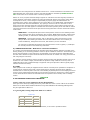
HVT Inc. Service Manual
INSTALLATION, MAINTENANCE, WARRANTY, SAFETY AND STORAGE INSTRUCTIONS
WARNING – Failure to comply with the instructions could result in serious bodily harm or property
damage and will void the warranty.
[email protected]
www.thehurleygroup.com
Phone: 705-682-0862
Fax: 705-682-2572
Sudbury, Ontario, Canada
Table of Contents
Pre-Installation
• A.) Introduction
• B.) Safety precautions
• C.) Shipping and Receiving
• D.) Handling
• E.) Storage
Fan Application
• A.) Installation
• B.) Blade angle Settings
• C.) Balance
• D.) Recommended Torque - Fan blade nuts and motor mounting hardware
• E.) Motors and Controls
• F.) Sound Considerations
• G.) Vibration Detectors
• H.) Paint
Operation
• A.) Bearing vibration Limits
• B.) Bearing Temperature limits
• C.) Start-up check list
• D.) Trouble-Shooting
• E.) Maintenance
Terms, Conditions and Warranty
[email protected]
A. INTRODUCTORY REMARKS
PRE-INSTALLATION
This manual is published to assist the customer in the storage, installation, operation, and maintenance
of Hurley Ventilation Technologies Inc. axial fans.
HVT Inc. warrants against defects in workmanship and material, refer to TERMS AND CONDITIONS
section.
In general, the HVT Inc. fan is a high performance, variable pitch vane axial fan. It is a quality product
built to operate in harsh mining environments and with proper care and maintenance should give many
years of satisfactory, trouble free operation.
B. SAFETY PRECAUTIONS
WARNING – Contact with rotating fan blades can cause severe injury or death. Never insert items into
the fan to determine movement or direction of rotation. Install fan guards or screens on arrangements
with exposed fans. Always use lockout and tag out procedures before performing fan adjustments,
maintenance, service or inspection.
It is the responsibility of the purchaser to insure that qualified personnel experienced in installing this
type of equipment handle the installation. The personnel should be experienced, trained and aware of
the hazards associated with electrical rotating equipment, failure to comply with these practices may
result in serious bodily injury or death.
THE FOLLOWING SAFETY PRECAUTIONS MUST ALWAYS BE OBSERVED:
I.
II.
Maximum operating temperature and speed for fan equipment must not be exceeded.
Bearing temperature must not be exceeded. Refer to bearing temperature limits located in
"OPERATION."
III.
Protect properly against electrical hazards related to motor operation. Refer to specific information
supplied on motor installation.
IV.
Protective guards for shafts, couplings, heat flingers and belts must be provided and in place
during operation.
V.
VI.
VII.
Inlet and outlet screens help prevent entrance of clothing and other foreign objects into rotating
parts.
Access doors to fan or duct system must never be opened during fan operation. Those located on
the discharge side of the fan may open violently if opened while fan is operating.
To provide against possible electrical start-up of fan during maintenance, be sure to electrically
lockout equipment before working on fan.
III.
Beware of hot surfaces. Allow sufficient cool-down period before beginning any maintenance work.
IX.
Remove all loose materials from inside of housing and ductwork prior to start up. Check the
quality of air inside the fan and provide a watchman outside the fan before allowing anyone to
enter.
X.
XI.
XII.
Inspect the fan rotor on a regular basis. The rotor is subjected to stresses from centrifugal force
and vibration. It may also be exposed to particulate erosion (wear) and/or corrosion attack. A
careful visual inspection of the cleaned rotor by a knowledgeable inspector should be performed
periodically to insure that no cracking or other structural damage has occurred. Do not operate
the fan if it has cracks or structural damage.
The vibration of the fan should be carefully monitored. Be sure that vibration instruments are
operating properly and that they are calibrated frequently.
For further safety practices, refer to AMCA Publication 410.
C. SHIPPING AND RECEIVING
Upon arrival of the equipment, check that all items on bill of lading and/or invoice have been received.
Partial shipments are often made.
All shipments are thoroughly inspected prior to shipment. Regardless, rough handling enroute may
damage the fan components. The receiving party must thoroughly inspect all shipments for possible
damage. Any damaged parts are the responsibility of the carrier and should be reported to him
immediately upon arrival.
HVT Inc. cannot be held responsible for adjustment of such claims if the delivery receipt is signed
without specific notation of shortage or damage. Any damages noticed after delivery should be reported
to the carrier at once. Request their inspection of the shipment and fill out a concealed damage
inspection report.
HVT Inc. must be notified in writing immediately of any lost or undelivered parts. Complaints issued
more than 30 days after delivery may not be reviewed by HVT Inc.
D. HANDLING UNITS SHIPPED COMPLETELY ASSEMBLED
Fans arriving at the job site assembled can be picked up using slings and padding or spreaders to avoid
damage. Where slings are used, they should be placed at the lifting lugs. ALWAYS MAKE SURE THAT ALL
LIFTING AND HANDLING EQUIPMENT AND TECHNIQUES CONFORM TO CURRENT SAFETY STANDARDS.
Avoid lifting fans or parts of fans in a way that will concentrate stresses that may bend or distort fan
parts. Never pass slings or timbers through the inlets of the fan housings.
THE FOLLOWING MUST ALSO BE OBSERVED DURING HANDLING:
1. Never allow chains to be in contact with the rotor during lifting.
2. Be sure that slings are not damaged in any way and are rated to lift the weight of the fan equipment.
3. Never lift rotor by blades or flanges.
E. STORAGE
1. STANDARD REQUIREMENTS
HVT Inc. fans are suitably prepared at the factory to protect them during shipment to the job
site and for a reasonable period before installation. If not installed immediately, the fan should
be protected to remain dry at all times.
For shipment of assembled fans, the rotor may be blocked or strapped to avoid rotation during
shipment. Be sure to remove the blocks or straps prior to operation.
2. LONG-TERM REQUIREMENTS
If fans must be stored for an extended period, the storage site should be a clean, dry, wellventilated, properly drained, temperature controlled environment (10-50ºC) protected from
rapid and extreme changes in humidity and free of any shock or vibration of 2 mils maximum
at 60 hertz, to prevent motor bearings from brinelling. All units equipped with space heaters
are to have the heaters connected if storage conditions exceed these environmental limits.
For pre-assembled units, include room for inspection, lubrication, and maintenance, such as
turning the fan rotor by hand to make certain all parts retain proper lubrication and shaft does
not take a set. When the fan is in storage for more than three months, the rotor should be
rotated manually every three months. Rotors are to be marked such that a different blade is in
the vertical position after each rotation.
Motor windings are to be meggered at the time of storage and also at the time of storage
removal with the values recorded. Any drop in resistance value greater than 50% will
necessitate electrical or mechanical drying of the motor. Further, motor bearings should be
checked for moisture. If moisture is present, the bearings should be replaced. NOTE: Industry
standards dictate that a motor should megger at least 1 megohm plus KV rating of motor as
new. Therefore, megger reading after storage should not be less than 1 megohm.
3. BEARING PROTECTION (PERTAINING TO BOTH SHORT AND LONG TERM STORAGE)
Prior to shipment, fans are factory tested. All bearings are prelubricated and should not require
additional grease for start-up. If the fan is not expected to be put into use immediately, it is
advisable to add lubricant so as to destroy any air gaps in the bearing reservoir, which may
collect moisture. At start-up, excess lubricant will be released through the seals. This is a
normal purging action, which will permit cooler operation, and the lubricant should not be
replaced.
NOTE: Extreme caution must be taken not to contaminate bearings when working on them.
Upon removal from storage, the following procedures should take place:
1. Thorough examination to insure that no build-up of foreign material has occurred from the elements
or near-by processes.
2. Examination to make certain that paint or coatings, and all other components are still in excellent
operating condition.
3. Bearings re-lubricated to specifications as described in lubrication section.
FAN APPLICATION
Improper duct design can cause a system effect that decreases fan performance. When connecting the
fan to the ductwork, care should be taken to avoid twisting or deforming of the housing as this may
cause the blades to strike the fan casing and/or cause vibration and noise problems.
Fans with open inlets require the use of an inlet bell or cone. Published fan performance and efficiency is
based on the use of these items. Operation of the fan without these accessories will result in decreased
performance and increased noise levels; furthermore a bad inlet condition could lead to premature rotor
failure. There should be a distance of at least two fan diameters from the face of the inlet bell to an
obstruction such as a wall. The minimum free distance from the inlet to either side or the roof should be
one fan diameter.
Whenever feasible a diverging cone on the fan discharge should be installed in order to minimize the
velocity pressure loss and regain static pressure.
Elbows immediately adjacent to the fan inlet and outlet should be avoided. When elbows are used,
turning vanes should be installed to minimize turbulence to the air entering the fan.
Butterfly dampers are not recommended for throttling at the fan inlet. Refer to AMCA Publication 201
"Fans and Systems" for additional information on duct design and system effects.
WARNING: Axial fans should not be operated in the stall/surge region. The stall/surge region is defined
as any region in which the system resistance line does not pass through the normal operating curve.
Any attempt to operate this equipment in this stall region can be extremely dangerous and may result in
damage to equipment as well as nearby personnel.
Typical symptoms of fan operation in the stall region:
• Marked decrease in volume.
• Marked decrease in amperage.
• Marked decrease in pressure.
• Marked increase in noise level.
• Marked increase in vibration levels.
The depth of the stalling dip and the amount of the marked decrease or increase is directly related to the
hub-tip ratio of the fan.
Fans with smaller diameter hubs and longer more slender blades have a much less pronounced stalling
dip and corresponding decreases or increases than does a fan with a large hub and short blades.
It should be noted that operating a fan in the stalling range for prolonged periods could result in
premature mechanical failure due to excessive vibrations and / or resonance and blade loading
fluctuations which can cause cyclic bending of the blades, resulting in failure.
Pulsations or blowback can occur if a fan is operated too near its’ shut-off pressure in the unstable
region of the fan curve (stall zone). The fan will have unstable characteristics, as it hunts for a stable
operating point. Note however, that steady operation within this region is possible, however, most often
at a decreased flow rate but is not recommended.
A. INSTALLATION
NOTE: BE SURE THAT ALL EQUIPMENT IS ELECTRICALLY LOCKED OUT DURING ALL PHASES OF
INSTALLATION.
B. BLADE ANGLE SETTINGS
On all fans, the blade angles have been pre-set at the factory for the duty required. The blade index range
is numbered from 0-6 for type 2000 and 3000 blades and 0-16 for the type 1000. The number 0 is the
highest angle of attack in all three-blade types and as such requires the greatest brake horsepower. As the
setting moves towards the higher number setting – 6 or 16, the flow, pressure and brake horsepower are
reduced. In order to determine the correct blade setting for a given blade tip angle, reference the “Blade
Setting versus tip angle degree Chart”. Should it be necessary to re-adjust blades, be sure that each blade
is set at the same index number. Furthermore, it is recommended to verify the blade tip angle degrees
with a protractor, as the numbered settings are provided for convenience and allow for quick
approximate field adjustment. Once adjustments are completed, the rotor should be turned by hand to
ensure that none of the blades are striking the shell casing or bulkhead support. Motor amperage should
be verified once the fan is energized to prevent motor overload, maximum amperage draw is indicated
on the exterior of the fan casing on the fan and/or motor nameplate.
To adjust blades, the following procedure should be used:
a)
Mark the aluminum spun nose cap relative to the hub and mark fasteners and extra washers
(trim balance weights).
b) Remove cap and store the mounting hardware.
c) Loosen the blade locking nuts.
d) The ideal method for establishing the correct blade angle is by using a protractor to set the
blade tip angle degrees. The numbered settings are for working approximations.
e) Tighten the lock nuts to the appropriate foot-pounds of torque based on Table I in the
“Recommended Torques for Fan Blade nuts and motor mounting bolts” section. During the
tightening process the blade position should be held in position to ensure that the selected
position does not change.
f) After setting all blades, a check should be performed to ensure identical blade positioning of the
complete set.
g) Re-install the nose cap by matching the mark placed in step a) and replace all fasteners and
washers in their original positions to ensure original factory balance quality.
Due to the fact that only one half hour to one hour of labor is required to perform a blade angle change
on any adjustable pitch fan, it is the responsibility of the customer to adjust the blade settings. The
motor-nameplate current is not to be exceeded when the ventilated system is operational.
C) Balance
The fan was operated/tested at full voltage/rpm and dynamically balanced to a precise
degree during assembly. Our factory recommended specifications, are listed below in
the table titled “HVT Standard Vibration limits”. This balance must be maintained to
assure long and faithful operation.
HVT Fan Standard Vibration Limits
RPM
SMOOTH
ALARM
SHUT DOWN
3600
.5mils / .09 Vel.
1.3mils/ .25 Vel.
3.0mils/ .56 Vel.
1800
1.0mils/ .09 Vel.
2.6mils/ .25 Vel.
5.0mils/ .47 Vel.
1200
1.5mils/ .09 Vel.
4.0mils/ .25 Vel.
7.0mils/ .44 Vel.
900
2.mils/ .09 Vel.
5.3mils/ .25 Vel.
8.0mils/ .38 Vel.
CAUTION: Do not attempt to balance a mechanical problem or a dirty fan.
D.) RECOMMENDED TORQUES FOR FAN BLADE NUTS AND MOTOR MOUNTING BOLTS.
TABLE I. Fan blade nuts.
Rotor SIZE Torque (ft-lbs)
14”
130
17”
130
18”
180
21”
220
26”
220
30”
450
TABLE II. Motor mounting bolts.
Bolt Size Torque (ft-lbs)
1/2”
120
5/8”
160
E.) MOTORS AND CONTROLS
HVT INC. STANDARD FAN APPLICATION MOTOR SPECIFICATIONS
HURLEY VENTILATION TECHNOLOGIES INC. IS PLEASED TO PROVIDE TOSHIBA PREMIUM
AND HIGH EFFICIENCY AC INDUCTION MOTORS AS A STANDARD IN OUR FANS.
EFFICIENCY: PREMIUM
ENCLOSURE: TEAO
SERVICE FACTOR: 1.25
INSULATION CLASS: F
BEARINGS: ANTI FRICTION
HIGH TORQUE DESIGN: B
VOLTAGE: 380/440/575V/3ph/50-60cy MOUNTING: HVT C-FLANGE FLANGE MOUNT
COMPLETE WITH: CAST IRON FRAME
CAST IRON END BRACKETS
CAST IRON OVERSIZED CONDUIT BOX ON 575V MOTORS
ALKALYD PAINT FINISH (GRAY)
TWO (2) DRAINS IN FRAME
OVERSIZED BEARINGS
CSA APPROVED AND UL RECOGNIZED
STAINLESS STEEL NAMEPLATE
HVT AXIAL FAN DESIGN AND SPECIFICATIONS
Note: Other motor manufacturers drives can be supplied upon request.
1.
STARTING TIME
The starting time can be calculated as follows:
time = (WR²) (delta RPM) / (307.2) (avail. torque)
time (seconds)
delta RPM = change in speed (rev/min)
avail. Torque = (motor torque capability)-(fan torque requirement) at all speeds from zero to
normal operating speed (lb-ft)
WR² = fan rotor rotational moment of inertia (lb-ft²)
Most single speed fans will achieve full operating speed in 25 seconds or less. Longer starting
times can result in motor overheating. The following are typical causes of excessively long
starting time:
1.
Driver torque not adequate for fan rotor WR² and the fact that it may be used with any
standard motor.
2.
Low voltage, causing reduction in motor torque capability. The high starting torque and
high starting current may shock the driven fan equipment.
3.
Partially open fan inlet damper, causing increase in fan torque requirement.
4.
Low temperature (high density gas) causing increase in fan torque requirement.
5.
Driver speed-torque curve not providing enough available torque when compared to fan
torque requirement.
NOTE: Drivers are often sized for the operating horsepower at process temperatures and are
incapable of starting the fan at cold conditions unless the inlet damper is fully closed
throughout the start-up.
2. MOTOR OVERCURRENT PROTECTION CONDITION.
The electric current during starting is typically 5 to 7 times the motor full load current. Motor
thermal overload protection is recommended to prevent burnout from misapplication or
excessive number of starts. Thermal overload protection must be selected to allow high current
for up to 25 seconds or more in some cases when starting high-inertia fans. Electric Code may
allow dual element time delay fuses to be rated at 125% of the motor full-load current for all
AC squirrel cage motors with full voltage, resistor, reactor, or auto-transformer starting under
normal conditions. In cases where this rating is insufficient for the starting current of the
motor, the rating of the fuses may be increased up to a maximum of 140% of the motor fullload current.
3. STARTERS AND CONTROLS
Full Voltage Starting (Across-the-Line) initially connects the motor directory to the power lines.
The advantages of this method are its low cost, high starting torque, low maintenance, and the
fact that it may be used with any standard motor. Note that the high starting torque and high
starting current may shock the driven fan equipment.
Auto Transformer Starting (Reduced Voltage) limits input voltage and reduces inrush current.
Normally an adjustable timer is provided for switching to full voltage after the motor has
partially accelerated. Note that motor output torque is reduced by the square of the voltage
reduction at the motor and, therefore, starting time is extended.
Wye Start/Delta Run allows starting at reduced phase voltage, reduced load and inrush current.
Starting voltage is full voltage divided by the square root of three. High transient currents are
possible at the transition from wye to delta. This is a non-standard motor connection that must
be specified at order time.
Note the full load amperage and the motor service factor as listed on the motor nameplate.
Monitor the motor current and DO NOT OPERATE THE MOTOR IN AN OVERCURRENT
CONDITION. In most cases the fan must be connected to the system ductwork and/or dampers
closed to provide a system resistance before operating the fan.
In general, on motors above 200 HP, do not restart more than once every 30 minutes. Detailed
start-up limitations are available from the motor manufacturer.
4. VARIABLE FREQUENCY AC APPLICATIONS
Operation below 30% of the motor normal speed at 60 Hz should be reviewed with the drive
supplier. Variable frequency drives should be properly matched to the motor.
Belt drives are not recommended for variable speed applications.
6.
MOTOR BEARINGS
Refer to motor manual for motor bearing lubrication instructions (general guideline below). The
recommended vibration alarm and shutdown limits for the motor bearings are the same as the
limits for the fan bearings. Motor bearing loads must be adequate for rotor weight on
Arrangement #4 and for belt pull on Arrangement #1 and #9.
Service Conditions
Standard Duty
8 hours/day, light to normal loading, clean
condition, free from dust.
Severe Duty
24 hours/day, or light to normal shock
loading vibration, exposure to dirt or dusty
conditions.
For very severe conditions where the
motor is subject to high vibration or
heavy shock loading and vibration use
1/3 of the value shown in the severe
duty table.
Very Severe Duty
24 hour/day, high ambient, normal to high
shock loading, vibration, dusty conditions,
confined mounting conditions
Greasing Intervals
RPM Range
FRAME
Standard Duty
Severe Duty
Very Severe
Duty
3600
143T – 256T
8 months
4 months
1 month
3600
284T – 365T
8 months
4 months
1 month
3600
404T – 447T
8 months
4 months
1 month
RPM Range
FRAME
Standard Duty
Severe Duty
Very Severe
Duty
1800 - 900
143T – 256T
30 months
12 months
4 months
1800 - 900
284T – 365T
24 months
12 months
4 months
1800 - 900
404T – 447T
18 months
8 months
3 months
7.
Other notes:
Drive rotation must match required fan rotation for full flow operation per fan curve. Note that
fan rotation is "as viewed from the motor end" and motor rotation is "as viewed from the end
bell" (opposite the shaft end).
F.) SOUND CONSIDERATIONS
Sound Power Level ratings shown are decibels referred to 10-¹² Watt and obtained in accordance with
AMCA Standard 300. Sound Power Level for each band and dBA are calculated per AMCA Standard
301. Levels shown do not include motor or auxiliary equipment.
Data is for use by a system acoustical design engineer for evaluation of the fan singularly and within a
system. Because of the infinite variations in system arrangements and the many factors, which affect
sound pressure levels, it is the designer's responsibility to properly apply this data based on his
knowledge of the system. Some guidelines for use of this data are: for "NEAR FIELD" reported data to
apply to ducted inlet and outlet installations, any opening in the duct must be a minimum of 100 ft.
away from the fan. Openings within this range are assumed to emit a sound pressure equal to the fan
Sound Power Level. This also applies to untreated inlet and outlet expansion joints. Note that for ducted
inlet/outlet the ductwork thickness must equal the fan housing thickness to achieve the Sound Pressure
Levels noted.
NEAR FIELD - A hemispherical space where sound pressure waves from one radiating surface
tend to interfere with waves generated by other surfaces. NEAR FIELD boundary, distance from
radiating surface, is related to the wavelength of lowest frequency and overall size of source.
FREE FIELD - Area beyond near field, with no obstructions, where Sound Pressure Levels
decay 6 dB for each doubling of distance from near field. Effects of the room constant (for
indoor installations), background noise levels, and directivity are not considered.
The tolerance on Estimated Sound Power and Sound Pressure Levels is typically +/-2 dBA plus
the accuracy tolerance of the measuring instrument.
G.) VIBRATION DETECTORS – Main Mine or critical fan installations
It is strongly recommended that bearings be equipped with seismic vibration detectors mounted on the
bearing housing or on the bearing pedestal. This is an option available to customers. Accelerometer type
devices mounted directly on the bearing are recommended. Such units should have adjustable alarm
and shut down vibration set points and solid-state electronics that are reliable over a long period of time
with a high degree of accuracy.
The operation of these vibration pickups should be checked monthly and calibrated at least once every 6
months. The use of these is highly recommended as operation at high vibration levels may result in
catastrophic failure with resultant damage to equipment and injured personnel. Others typically supply
vibration monitors and wiring.
H.) PAINT
Steel equipment will normally be supplied with two coats of red oxide primer (suitable for acceptance of
a wide range of customer finish coats) unless special paint is requested. No paint will be applied to
stainless steel or aluminum parts. Take care in the handling of painted parts to avoid scraping that could
result in rusting. Painted steel parts that are to be stored more than two months prior to being placed in
service should be stored indoors at reasonable levels of temperature and humidity. Refer to storage
section.
OPERATION
A. RECOMMENDED OPERATIONAL PARAMETERS
BEARING VIBRATION LIMITS (identical to the fan vibration limits)
Alert supervision when any reading increases by more than 50% in one week or if the levels exceed the
alarm level as shown in the attached vibration severity chart. Shutdown for balancing and inspection
may be required above this level.
As a general guide, bearing temperature limits are as follows:
Lubricants
Condition Standard
Synthetic
Normal
80º C or lower 110º C
Alarm
90ºC
Shutdown 100º C
120ºC
130ºC
Do not run bearings at excessive temperatures; it can result in premature failure.
B. START-UP BEFORE STARTING FAN, COMPLETE THE FOLLOWING LIST:
1.
Lock out the power source.
2.
Rotate rotor to see that it does not rub and maintains proper inlet piece/rotor clearances.
3.
Check fan and ducts for any foreign material or dirt build-up.
4.
Secure all access doors.
5.
Check lubrication of bearings, couplings, drives unit, etc.
6.
Secure and check safety guards for clearance.
7.
Bump start and check for proper rotation.
8.
Start the equipment according to recommendations of drive unit and of starting equipment
manufacturers.
9.
Allow fan to reach full speed, and then shut down. Make immediate corrections if any
vibrations or unusual sounds have been detected.
C. TROUBLE-SHOOTING
TROUBLE-SHOOTING GUIDE
PROBLEM:
Vibration and noise
1. Loose or broken bolts, O.D.E motor supports or setscrews.
2. Defective bearings or rubbing shaft seal.
3. Out of balance fan wheel.
4. Weld cracking.
5. Improper fan wheel clearance to inlet piece(s), rubbing.
6. Material build-up and/or wear on wheel or foreign material in housing.
7. Improper wheel rotation.
8. Operation near system critical speed.
9. Shaft bent or distorted.
10. Defective motor.
11. Resonant frequencies of structural steel.
12. Beat frequency with other fans on common base.
13. Loose hub to shaft fit.
Duct Pulsation
This often occurs when a fan is operated on a system with high resistance. The fan is forced to
operate far below the normal or design volume. If the operating volume is lower than the value
corresponding to the fan's peak static pressure, instability (surge) can occur. Possible solutions
include:
1.
Increase operating volume (reduce system resistance).
2.
Recirculate a portion of the air back to the fan inlet.
High Motor Temperature
1.
2.
3.
4.
Improper ventilation of cooling air to motor, (may be blocked by dirt).
Input power problems, (especially low voltage).
High amperage.
High ambient temperature
Poor Performance
1. Damaged rotor assembly.
2.
3.
4.
5.
6.
Incorrect fan rotation.
Poor duct design on inlet or outlet. Air leaks in the system.
System resistance is excessive compared to design requirements.
Fan speed too low/high.
Density may be different than design density.
High Bearing Temperature
1.
2.
3.
4.
5.
6.
Lack of lubrication.
High ambient temperatures or direct exposure to sunlight.
Improper location not enough room for free axial
Defective bearings.
Over lubrication.
Improper lubrication or contaminated lubricant.
Excessive Starting Time
1.
2.
3.
4.
5.
6.
Motor improperly sized for fan wheel WR².
Inlet dampers not closed during start-up.
Properly selected time-delay starter/fusing required.
Temperature at Inlet is excessively low (high density).
Low voltage at motor terminals.
Inadequate system resistance.
NOTE: Do not exceed motor manufacturer's specified number of starts per hour.
D. MAINTENANCE
PREDICTIVE MAINTENANCE
Routine vibration monitoring and trend analysis is recommended. This allows early detection of
problems so that potentially hazardous operation or unscheduled shutdowns can be avoided. Contact
HVT Inc. for more information on this service.
TERMS AND CONDITIONS OF SALE
CONTRACT AND ACCEPTANCE
Seller’s acceptance of this order is expressly conditioned on Buyer’s assent to the terms contained herein. An
authorized employee of Seller at its factory must accept all orders.
SHIPPING SCHEDULE
Seller will establish shipping schedules as closely as practicable in accordance with Buyer’s requested delivery date.
However, Seller shall not be responsible for delays in performance resulting from causes beyond its control or the
control of its suppliers or subcontractors; including, but not limited to any casualties, acts of Buyer, strikes or other
labour difficulties, shortages of labour, supplies and transportation facilities. Seller reserves the right to ship in advance
of any Buyer request dates, except those dates stipulated “Not Before”. Should shipment be held beyond scheduled
date for the convenience of Buyer, the Seller reserves the right to bill immediately for the goods and to charge Buyer for
reasonable expenses incident to such delay.
PRICES
All quotations expire sixty (60) calendar days from the date of quotation unless otherwise stipulated. Prices of products
scheduled for shipment more than twelve (12) months after the date of Buyer’s order shall be subject to escalation.
TERMS OF PAYMENT
Subject to the approval of Seller’s Credit Department, terms of payment are net; thirty (30) days unless otherwise
stipulated.
TAXES
Seller’s prices do not include any applicable sales, use, excise or similar taxes. If, under any law or regulation in effect,
the Seller is required to pay or collect any tax upon the products arising from the sale, transportation, delivery, use or
consumption of said products, whether directly or indirectly, the contract price shall be increased by the amount of any
such tax.
TERMINATION
In the event Buyer terminates all or any portion of an order, for reasons other than Seller’s default, Buyer agrees to pay
the costs already incurred by Seller to date of cancellation, including the price of any goods or services required to fill
the order already committed to by Seller and a reasonable allowance for overhead and profit.
WARRANTIES
Seller warrants that the products covered by this contract conform to applicable drawings and specifications accepted
in writing by Seller, will be free from defects in material and workmanship will be merchantable and will perform in
accordance with the detailed specifications accepted in writing by Seller. These warranties extend for a period ending
twenty-four (24) months from the date of shipment. Buyer’s exclusive remedy and Seller’s sole responsibility under
these warranties is to repair, replace, or refund the amount paid for such part or product. These warranties exclude the
cost of removal or reinstallation. For purposes of remedying any defects, Buyer agrees to provide Seller with
reasonable assistance and access to the Work. Component parts and accessories not of the Seller’s manufacture are
warranted only to the extent that the manufacturers thereof warrant them. THERE ARE NO OTHER WARRANTIES,
EXPRESS OR IMPLIED, WHICH EXTEND BEYOND THOSE SET FORTH ABOVE. THE WARRANTY OF
MERCHANTABILITY IS LIMITED TO THE TIME PERIOD SPECIFIED ABOVE. These warranties are contingent upon
the product being stored, installed, maintained, and operated in accordance with good engineering practices and the
instructions contained in the Seller’s Operating and Maintenance Manual. Claims for expenses of Buyer relating to
labour and/or material supplied by Buyer (commonly known as “Back charges”) will not be honoured by Seller unless
Buyer obtains the prior written consent of authorized personnel at Seller’s factory to supply such labour and/or material.
TRANSPORTATION CHARGES AND RISK OF LOSS
Unless otherwise agreed all shipments are f.o.b. factory. Risk of loss for the products sold hereunder passes to Buyer
upon delivery to the carrier.
LIMITATION ON LIABILITY
Seller’s total responsibility for damages (whether arising in contract or tort) arising out of or relating to its performance
of this contract or the products covered hereunder shall be limited to the contract price for the product. In no event
shall Seller be liable for any incidental or consequential damages such as lost profits, loss of use of productive facilities
or equipment, lost production, or expenses incurred in reliance on Seller’s performance, whether suffered by Buyer or
any third party. Nothing in this paragraph shall in any way be construed to affect the liability Seller may have for
personal injury or death of any third party.
INDEMNITY
Seller shall indemnify Buyer from all liability, including reasonable attorney’s fees, for personal injury or death to any
third party, arising out of the sole negligence of Seller, its agents, servants or employees, while Seller is on Buyer’s
premises in the performance of this contract.
MODIFICATION
This contract constitutes the entire agreement between Buyer and Seller relating to the products supplied hereunder.
All modifications to the contract must be by written agreement. Any charges in specifications, quantities, schedules,
materials or services requested by the Buyer shall be subject to an equitable adjustment in the contract price, time of
performance, or both.