1
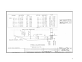
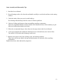
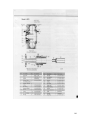
1448 STANDARD CENTRIFUGE OPERATIONS MANUAL Revised January 2005 3520 East Belt Houston, Texas 77015 (713) 455 – 9600 ● Fax: (713) 455 – 7753 (800) 441 – 4850 www.hutch-hayes.com 1 Hutchison Hayes, L. P. NOTICE OF CONFIDENTIALITY This information is highly confidential and is solely for the benefit of Recipient 2 TABLE OF CONTENTS 1448 STANDARD CENTRIFUGE OPERATIONS & SERVICE MANUAL SECTION 1 - INTRODUCTION Overview Data Page 5 SECTION 2 -START-UP Safety Installation Pre Start – Safety Precautions Belt Tension Procedure Starting & Shutdown Procedure 8 SECTION 3 - OPERATION A. Over-Torque Protection & Resetting. Standard Warning Torque Lever & Setting 22 B. Cleaning C. Dam Plate Adjustment Pond Depth Chart SECTION 4 - LUBRICATION A. Grease & Oil Data Lubrication Schedule 28 SECTION 5 - DISASSEMBLY & ASSEMBLY A. Gearbox Removal B. Rotating Assembly Removal C. Conveyor Removal 1. Conveyor Disassembly D. Pillow Block Disassembly E. Front Bowl Hub F. Rear Bowl Hub G. Assembly & Disassembly Tips H. Recommended Capscrew Seating Torque I. Conveyor, Wear Protection 34 SECTION 6 - PLANETARY GEARBOX & BACK DRIVE ASSEMBLY 59 3 Page SECTION 7 - PARTS LIST Base Unit Standard 68 SECTION 8 - ELECTRICAL & WIRING Standard 74 SECTION 9 - TROUBLE SHOOTING Standard 78 SECTION 10 – ELEVATION, DIMENSIONS & WEIGHTS Standard 81 SECTION 11 - MISCELLANEOUS Recommended spare parts list Standard Charts Storage 88 SECTION 12 - VENDOR DATA 96 4 SECTION I INTRODUCTION 5 OVERVIEW HUTCHISON HAYES CENTRIFUGE STANDARD MODEL 1448 This Service Manual describes the centrifuge, and lists instructions for the installation, operation, and maintenance requirements. The basic purpose of this centrifuge is to separate the liquid and solids from the fluid feed (slurry.) A stainless steel rotating bowl, driven by a 50 H.P. electric motor is used to centrifuge the slurry; that is to sling the solids against its inside wall surface while a stainless steel screw conveyor (faced with hard tiles) gathers and conveys these solids to a central discharge area. The conveyor is driven at a slightly slower RPM through a planetary gear reducer. The liquids migrate to the front end of the machine and are dispelled through four (4) adjustable plate dam openings, to a central discharge area. For a more comprehensive description of how the centrifuge operates, see the Operation Section of this manual. 6 1448 INDUSTRIAL MODEL CENTRIFUGE DATA Using P-52 Gear Unit: Normal Bowl Centrifugal Force Normal Bowl Operating Speed: Normal Conveyor Operating Speed: 2118 G’s 3250 RPM 3187 RPM Max. Bowl Centrifugal Force: Max. Bowl Operating Speed: Max. Conveyor Operating Speed: 3180 G’s 4000 RPM 3926 RPM P-125 Gear Unit: Normal Bowl Centrifuge Force: Normal Bowl Operating Speed: Normal Conveyor Operating Speed: 2118 G’s 3250 RPM 3224 RPM Max. Bowl Centrifugal Force: Max. Bowl Operating Speed: Max. Conveyor Operating Speed: 3180 G’s 4000 RPM 3968 RPM P-52 Gear Unit: Max. Output Shaft Torque: Max. Pinion Shaft Torque: Ratio: 52:1 18,000 LB. IN. 320 LB. IN. P-125 Gear Unit: Max. Output Shaft Torque: Max. Pinion Shaft Torque: Ratio: 125:1 Rated Solids Output: 18,000 LB. IN. 180 LB. IN. Centrifuge Bowl Inside Diameter: Bowl Length: 6,000 LBS./HR. 14 IN. 48 IN. 7 SECTION 2 START-UP 8 SAFETY Because the Model1448 Centrifuge is a high-speed, high-torque piece of rotating machinery, caution should be exercised by operating personnel. HH recommends operating personnel review the centrifuge manual before working with the equipment. Periodic safety meetings to familiarize new operating personnel with the centrifuges characteristics are also recommended. This manual is intended for use by qualified operators familiar with processing equipment and trained for this particular centrifuge. Maintenance personnel should be experienced mechanics. Electricians should be licensed, qualified personnel familiar with electrical safety procedures. CAUTION Persons without recommended experience may not understand the instructions listed in this manual A. GENERAL 1. Read all manuals and instructions before attempting to install or operate equipment, and follow all recommendations. 2. Follow all lubricating and/or greasing procedures and schedules recommended in the equipment instructions. 3. If nameplates are lost, damaged, or removed, replace them. They have been affixed to the equipment to provide warnings, instructions, etc., for the maintenance and operating personnel. 4. Do not operate belt driven or chain driven equipment without guards. If equipment was purchased without guards, user is responsible for providing proper guards that meet all applicable codes. 5. Make periodic checks for loose bolts on rotating assemblies, the supporting structure, covers, hatches, guards, and piping connections. 6. Do not operate equipment if excessive vibration or abnormal noise develops. 7. If the equipment is supplied with covers or guards, do not remove these until the equipment has come to a complete stop. 8. Never operate equipment with parts that have not been manufactured or approved by the original equipment manufacturer. B. HANDLING 1. Safe practices for lifting and handling equipment should be followed. Hoists and slings should be of adequate capacity, inspected regularly, and in good repair. 9 2. Always use extra caution when lifting, moving, or holding worn parts, since these may be sharp, slippery, or weakened. Never place hands, feet or head at possible pinch points. 3. Always provide a sufficiently large cleared area around the equipment during maintenance. C. ROTATING EQUIPMENT 1. Do not exceed the maximum speed, process material specific gravity, process pressure or temperature, or maximum design feed rate as specified on the equipment nameplate or within the operating manual. 2. Do not use a pipe wrench on any part of the rotating equipment. 3. Do not interchange parts that have been balanced as an assembly. 4. Do not attempt to utilize the rotating equipment in an application for which it was not originally selected. 5. When taking samples or removing any material from equipment like grinders, screw conveyors, open throat pumps, etc., make sure all machine components are at rest and the power is shut off with the disconnect switch locked in the off position. 6. Do not get rags, loose clothing, sticks, etc., near rotating or moving parts. 7. The equipment must coast to a complete stop. Do not brake it by hand or in any other way force it to stop, unless it is equipped with a braking mechanism supplied by the original equipment manufacturer. 8. Do not operate the rotating equipment unless the direction of the rotating part or assembly conforms to that of the Instruction and/or Operation Manual. 9. If a rotating assembly must be turned by hand, use caution: Avoid sharp edges and close areas where fingers may be cut or trapped (example: pulleys). D. PUMP 1. If positive displacement pumps are used in the process be sure the discharge line is unobstructed before starting the pump. 2. In plants using any type of grinder with the discharge directly connected to a pump, be sure that the pump is in operation before putting any product into the grinder. 3. Do not run a positive displacement pump dry. E. EXPLOSION PROOF EQUIPMENT 1. Do not operate equipment driven by an explosion-proof motor and control until all seal fittings are properly sealed with recommended fiber or compound, and tagged. 2. Never use abrasive material or a file to remove corrosion from explosionproof equipment. 3. Cover screws and bolts used to hold explosion-proof joints together must always be tight, and only of the type and material recommended by the manufacturer. 10 F. MOTOR 1. Do not neglect to check that the line voltage applied to the motor controller is the same voltage for which the motor is wired. 2. Always follow motor manufacturer’s specifications on bearing lubrication. 3. Do not attempt to operate a motor that is overheated due to frequent starts and stops. Allow the motor to cool to ambient temperature (as designated on the motor nameplate) before each restart. G. ELECTRICAL (General) 1. Install and ground all equipment (permanent and portable) in accordance with requirements of the National Electric Code and local electric codes. 2. Use circuit breakers or fused disconnects between equipment and power source. 3. Never touch electrical components with wet hands or when standing on a wet surface. Insulate yourself from ground and use insulated tools. 4. When handling electrical equipment, take care to avoid contacting live parts. Assume all circuits are live. Check with a voltmeter. 5. Label all control circuits clearly. 6. Keep electrical controls and motors clean and free of dust – dust prevents thorough air circulation, generating heat; heat in turn can ignite the dust or flammable vapors if present in the atmosphere. 7. Never wash electrical equipment unless it is constructed for that purpose. Never wash live electrical equipment. H. ELECTRICAL (Repairs) 1. Only qualified personnel, familiar with electrical safety procedures and the construction and operation of the equipment, should work on electrical equipment. 2. De-energize all power before opening any electrical enclosure, or before connecting and disconnecting test equipment and components. Provide a safety lockout at the power source. 3. Use only approved safety rubber gloves and mats, insulated tools, and eye shields when doing electrical work. 4. Periodically inspect and operate all of the automatic shut-off devices and monitoring systems provided. 5. On DC powered equipment, do not perform any inspection (mechanical or electrical) until the power has been turned off and disconnected, and all rotating assemblies have come to a complete stop. The moving motor may generate DC voltage feed back. I. CHEMICALS 1. If corrosive and/or toxic chemicals or solvents are used as part of the process or as cleaning materials: become thoroughly familiar with the properties of the products and their hazards, the precautions necessary to handle the product 11 safely, and follow all manufacturer recommendations for the type of product being handled. a. Use in well ventilated area and keep employee exposure below permissible limits. b. If flammable, take care to prevent fire or explosion. c. Avoid contact with the skin and eyes – wear goggles, gloves, shields, etc., as required by the nature of the solvent or chemical. 2. If in doubt whether a product is dangerous or not – Assume It Is. Take all necessary precautions to avoid personal injury. J. VENTILATION 1. Toxic fumes, if present in the system, must not be permitted to escape to the operating area. They should be adequately vented away form the worker in accordance with applicable environmental regulations. 2. If in doubt whether any vapor is toxic or not – Assume It Is. Take all necessary precautions to avoid personal injury or adverse health effects. Worker exposure should be maintained below the permissible limit and at the lowest feasible level. 3. If it is necessary to enter an area where toxic vapors are present, consult with responsible authorities for recommendations concerning safety. 4. Use NIOSH approved breathing apparatus when working with toxic or hazardous materials, or with materials that reduce the oxygen concentration in the air, such as carbon dioxide. K. COMBUSTIBLE PRODUCTS 1. If combustible products are used as part of the process or as cleaning products, become thoroughly familiar with the safety precautions necessary to handle the product. Follow all recommendations to avoid personal injury or property damage that could be caused by fire or explosion. L. PRESSURE VESSELS 1. Vessels operating under internal pressure should be maintained and inspected in accordance with the manufacturer instructions and/or applicable local or state codes. If corrosion or erosion is expected, frequency of inspection should be increased. Qualified personnel should make all necessary repairs. 2. Vessels operating under internal pressure should be provided with a safety device to relieve excess pressure in accordance with the Unfired Pressure Vessels Code. 3. Safety devices should be in good operating condition at all times. It is recommended that they be inspected and tested frequently and maintained in accordance with manufacturer instructions and/or applicable local and state codes. 12 4. If any repair on a safety device is necessary, return it to the manufacturer. Inexperienced personnel should never attempt repair. Any adjustment should be made according to the recommendations supplied by the manufacturer. 5. The outlet connections of all safety devices should be installed in a manner that will not cause injury to personnel should discharge or actuation occur. 6. Before attempting maintenance on pressurized equipment, reduce internal pressure to atmospheric pressure. M. HOT / COLD PRODUCTS 1. When working with very hot or very cold processes or products, extreme caution should be used to avoid personal injury. N. LEAKAGE AND SPILLAGE 1. Any leakage in the system should be quickly corrected. 2. Any type of spillage (oil, water, etc.) should be quickly cleaned off floors, walls, equipment, lines, etc., and the entire operating area kept clean. O. DANGEROUS MATERIAL APPLICATIONS Hutchison Hayes, L. P. makes both standard equipment and equipment furnished with certain explosion-proof accessories (motor, controls, etc.), as specified by the purchaser. Standard equipment not furnished with explosion-proof accessories must never be used with explosive, chemically unstable, or flammable materials of any kind. Severe personal injury or property damage could result. When we supply equipment furnished with explosion-proof accessories, whether we are the manufacturer or not, we warrant that the particular accessories we describe as explosion-proof comply with accepted industry standards for that term. However, this does not mean, and we cannot and do not guarantee, that one of our machines furnished with explosion-proof accessories is safe for use with explosive, chemically unstable, or flammable materials under ALL conditions. In some instances, it may be necessary for the user to equip the machine with safety devices not ordinarily placed on equipment of this type. In other cases, the application may be so hazardous that the only prudent operating procedure is to isolate the equipment in an expendable building and operate it by remote control from a safe distance. Because Hutchison Hayes, L. P. has no control over these potential dangerous operating conditions, we do not guarantee that equipment made by us can be safely used with explosive, chemically unstable, or flammable materials, regardless of whether we installed industry accepted explosion-proof accessories. The user has the responsibility for insuring that all precautions required by his particular method of operation have been taken. P. REPAIRS 1. Do not make mechanical or electrical repairs or attempt disassembly unless the equipment has come to a complete stop, the power is shut off, and a safety lockout or other padlock is installed on the disconnected circuit. The locking device should be tagged to identify the working party. 13 2. Do not make any repairs until dangerous vapors and gases are replaced with clean air. 3. Hutchison Hayes, L. P. should be consulted before attempting to make major repairs to any of the rotating equipment we manufacture. Under no circumstances should weld repair or other alterations be made to major rotating components without the full knowledge and assistance of qualified Manufacturer personnel. Failure to obtain this assistance may result in rupture of parts involved with possible injury to personnel or damage to equipment. 4. Repairs to hard-surfaced parts must be performed with strict quality control of materials and methods. Hard-surfacing materials are brittle, and can break off if improperly applied. After startup, periodic inspection of these parts is necessary to anticipate separation of materials. 5. During repairs, when equipment may be physically or electronically unstable, post barriers or signs announcing hazardous conditions. 6. After repairs and before restarting, reinstall all guards and reconnect all mechanical and electrical safety devices. Q. CORROSION, EROSION, AND PITTING OF ROTATING EQUIPMENT 1. To insure a high factor of safety under severe operating conditions, high speed rotating equipment manufactured by Hutchison Hayes, L. P. is designed after a careful stress analysis has been made of highly stressed parts. A thorough control of metallurgical properties is maintained throughout manufacture, and all material is warranted as free of defects at time of shipment. 2. It should be noted that equipment subjected to severe erosive or corrosive environment could deteriorate over a period of time, depending on the severity of the exposure and/or possible misuse. Users of high speed rotating equipment should be aware of the fact that extremely high forces are brought into play when their equipment is in operation. Any weakening of highly stressed members by misuse, erosion, corrosion, chemical pitting, or stress cracking must be guarded against to prevent possible metal failure. 3. In the interest of longer and safer operation of the equipment, Hutchison Hayes, L. P. recommends that the equipment owner maintain a periodic (at least monthly) inspection on highly stressed rotating and/or moving parts which are subjected to erosive or corrosive wear. 4. The following points should be noted and the recommended action taken: a. Do not operate equipment when: 1. Holes are wearing through rotating and/or moving parts. 2. Grooves greater than 1/16” deep are worn in rotating and/or moving parts. 3. Evidence of cracks is present, especially in rotating and/or moving parts. 4. Chemical pitting of 1/16” depth or greater on rotating and/or moving parts. 5. Component surfaces are covered with a light corrosion or etching. b. Chemical pitting is observed: 14 All cases of chemical pitting, even less than 1/16” depth, should be watched carefully. This pitting action is almost always due to the breakdown of the passive film on stainless surfaces in the presence of chlorides. This often occurs under product cake that has not been sufficiently cleaned from the surface. High temperature, low pH, and high acidity accelerate the pitting action. 5. Contact Hutchison Hayes, L. P. regarding the repair or replacement of rotating and/or moving parts whose surface is noticeably pitted. 15 INSTALLATION Location a. b. c. d. e. f. g. Install the centrifuge unit in a location where sufficient headroom is allowed for lifting the bowl out of its frame enclosure. A 2-ton overhead hoist should be installed to facilitate inspection or repair work. A clear area in the vicinity of the centrifuge should be provided to set the bowl during inspection or repair. Room should be allowed at the front end of the machine for withdrawing the planetary gearbox. A zone approximately 2’0” wide x 2’ 6” long from the front end of the gearbox should be kept clear. Room should be allowed at the rear end of the machine for withdrawing the feed tube. A zone approximately 6” wide x 3’ 0” long from the end of the feed tube support clamp should be kept clear. Clear access space should be provided around the centrifuge. The centrifuge isolators should set on a smooth level surface on structural members of sufficient strength. IMPORTANT CAUTION Since this centrifuge operates at high speed and is subjected to severe wear conditions, it is important that any indications of weakening of highly stressed components be recognized before a failure can occur. To facilitate this HH recommends a monthly visual inspection on highly stressed components, such as: The bowl Shafts Wear plates Wear tiles Conveyor, etc. If inspection reveals: 1. Holes worn through moving parts 2. Wear grooves greater than 1/16” thick in moving parts 3. Cracks present is moving parts 4. Chemical pitting to a depth of 1/16” or greater in moving parts DO NOT OPERATE THE EQUIPMENT UNTIL REPAIRS ARE MADE FAILURE TO FOLLOW THE ABOVE RECOMMENDATIONS MAY RESULT IN SEVERE PERSONAL INJURY OR PROPERTY DAMAGE 16 PIPING 1. Customer piping tie-ins to the centrifuge should be made with flexible connections. 2. Customer tie-in at feed tube should have a suitable pipe support so that no weight is imposed on the centrifuge feed tube. A flexible connection is required here. 3. A flush line should be provided at the feed tube tie-in. HH recommends hot water. A ball valve should be located as close as possible to the feed line to prevent plugging the flush branch with solids. 4. Use a screen at the pump suction to protect the pump and centrifuge from oversize solids. 5. Liquid discharge lines should have a minimum of ¼ " per ft. slope. 6. HH recommends installation of a pressure indicator in the feed line upstream of the customer tie-in to regulate the feed supply to the centrifuge. For HH 1448 centrifuges with Hydraulic Main Drive or Hydraulic Back Drive, the following hydraulic oil is recommended: MOBIL DTE 26. (See the Product Data Sheets on the following pages.) Caution: Other hydraulic oils should only be used with written confirmation that the oil conforms to the specifications on the MOBIL DTR 26 product. 17 PRESTART SAFETY PRECAUTIONS FAILURE TO FOLLOW THE RECOMMENDED SAFETY PRECAUTIONS LISTED BELOW MAY RESULT IN SEVERE PERSONAL INJURY OR PROPERTY DAMAGE Read through this entire list before attempting start-up Initial Installation 1. The correct bowl rotation must be verified. The bowl should rotate clockwise when viewed from the motor end (rear of centrifuge) looking inboard. 2. The drive group enclosure guard and the gearbox shroud must be secured in place. 3. Check to see that the centrifuge unit is clear of rags, ropes, wires, or any other material which could catch or snag rotating parts. 4. All bolts and capscrews must be engaged per recommended torque requirements shown in Charts 1 and 2 at the end of this section. 5. All rings and seals should be in good condition and securely fastened. 6. The centrifuge cover should be tightly secured. 7. The frame bolts should be fully tightened. 8. Check all lubrication points. (See Lubrication Section) 9. Verify that all seal fittings at explosion-proof motor and control are sealed with CHICO X Fiber and sealing compound. 10. The drive belt should be checked for correct tension. Caution: Over tightening belts can damage the fluid coupling. (See Figure 1 at the end of this list.) 11. Electrical grounding straps must be secured in place, where required. 12. Maximum Speed, specific gravity, or pressure, indicated on the centrifuge name plate is not to be exceeded. 13. No work is to be performed on the electrical system unless the power is shut-off. 14. Check the line voltage on initial start-up to ascertain that the voltage applied to the motor controller is the same voltage that the motor is wired for. 15. If excessive vibration is present during start-up, shut the unit down immediately and notify HH service representative. 18 16. Do not replace any damaged or worn out Machine Parts with other than HH replacements. 17. The customer may replace ordinary wear parts such as oil seals, o-ring and gaskets. A replacement list is in the Parts List Section. 18. Do not open the cover or attempt removal of a shroud or belt guard until the centrifuge is motionless. 19. Use the correct tools for any assembly or disassembly work. 20. Do not supply slurry into the centrifuge until the unit is fully up to normal operating speed. 21. If more than one (1) centrifuge is in operation, never attempt to exchange any machined parts. 22. Never use a pipe wrench on any part of the centrifuge. 23. There is a slow down period as the machine decelerates towards shut-down. Leave the cover shut until the centrifuge is motionless. Do not attempt any disassembly before the machine is static. 24. Never prop the centrifuge cover partially open by using blocks of wood or any other foreign object. IMPORTANT CAUTION 25. Whenever the centrifuge cover is opened for cleaning, inspection, etc., the one (1) hinge safety pins must be engaged to prevent accidental closing of the cover, this procedure should always be followed. 26. Flexible connections should be used at all customer piping tie-ins. 27. Do not attempt any repairs to the gearbox at the front of the machine beyond replacement of the pinion shaft oil seal. 19 1448 HIGH “G” CENTRIFUGE BELT TENSIONING PROCEDURE FIGURE 1. 20 START UP AND SHUT DOWN 1. Read through Pre-Start Safety Precautions. 2. Momentarily press the motor start button. The centrifuge will come up to full operating speed in two (2) to three (3) minutes. 3. Start the feed pump and open the feed supply valve. The Torque Control Limit Switch is interlocked with the Motor Control and will stop the motor if the conveyor becomes overloaded. 4. Check solids for dryness, and the liquids for clarity. 5. If the solids are too wet, or liquids are not clear enough, the four (4) Plate-Dams will have to be adjusted. Stop feed pump and centrifuge and go to operation section for information on Plate-Dam adjusting. 6. To shut down, slow the feed rate to 10 gallons per minute. 7. Push the stop button for the feed pump. 8. Start the flush water and continue to run centrifuge for five (5) minutes to clear any product still in the bowl. 9. Stop centrifuge and let it come to a complete rest before turning off flush water. 10. Once a week, manually trip the torque control linkage to verify that it is operating smoothly. 11. The centrifuge should be cleaned after each shutdown. (See Cleaning Bowl Section) 12. Never reach into a shrouded area while the centrifuge is running. 21 SECTION 3 OPERATION 22 OPERATION The slurry to be separated is pumped into the feed tube, axially located at the rear of the machine. The slurry is directed into a feed chamber where it is dispersed by four (4) externally mounted feed nozzles and directed by centrifugal force along and against the inside wall of the bowl. This ring of slurry or “pond” will contain solids against the bowl wall. These solids are scrolled forward over a “beach area” by the screw conveyor and discharged through four (4) ports at the solids end of the centrifuge located in the rear. The lighter liquids migrate forward and are discharged through four (4) adjustable plate dam nozzles at the liquids discharge area located at the front end of the centrifuge; i.e. the gearbox end. OVER-TORQUE PROTECTION A TORQUE CONTROL DEVICE is located at the front of the gearbox. If a predetermined torque limit on the screw conveyor is reached during operation, the device will trip and close a micro switch sending a signal to cut off the feed supply This protects the screw conveyor and the gearbox from over-torque damage. A torque arm, contacting a rub pad on a trip lever is held in balance by means of a spring loaded cylinder linkage. If the pre-set torque limit is exceeded, this torque arm will rotate the trip lever out of the way and the torque arm will rotate at the same RPM as the bowl. When this happens, no solids can be conveyed to the solids discharge ports. The spring loaded cylinder linkage will have tripped, and caused the feed to stop so no further accumulation of slurry can occur. When the torque-control device trips: a. Stop the centrifuge. b. Remove the gearbox shroud. c. Rotate the torque-arm clockwise by hand to determine if the screw conveyor is stopped by an accumulation of solids or debris. d. Replace the gearbox shroud and restart the centrifuge. e. If the gearbox rotates, the conveyor is blocked and will need cleaning. If the gearbox does not rotate but the centrifuge trips out immediately after restart, the bowl must be cleared by cleaning. 23 WARNING SUDDEN HIGH SPEED ROTATION OF THE TORQUE ARM An aluminum torque arm is externally mounted on the planetary gearbox first stage pinion shaft. This part faces against the pivot arm (lever) which when tripped through a spring-loaded compression link, mechanically operates a micro-switch causing motor shutdown. This happens if the centrifuge conveyor becomes jammed or locked-up and rotates the bowl. This aluminum torque arm, item 950 normally is stationary. However, it can come up to the bowl/gearbox rotating speed instantaneously without warning in the event of a conveyor jam. It is important that all operating personnel understand this hazard and at all times keep clear from this torque arm while the centrifuge is running. 24 25 CLEANING BOWL WHEN PACKED OFF 1. Flush the bowl with water before shutting down 2. When the bowl is flushed, stop the machine but continue flushing. 3. Rotate the bowl by jogging the motor. 4. If necessary open lid and install lock out pin to rotate bowl by hand in forward and reverse direction. CAUTION: When rotating bowl in reverse direction it is important to be aware that there is no torque protection or break over mechanism for the gearbox. Do not over rotate bowl in the reverse direction. Damage may occur to gearbox. NOTE: Rotating each way while flushing will move some solids to the liquids discharge and some flushing liquid to the solids discharge. If this is a problem, arrange to divert the liquids and solids discharge before cleaning. If cleaning does not remove solids deposits, the bowl will have to be pulled for inspection and further cleaning. Go to Disassembly Section. PLATE DAMS ADJUSTMENT 1. The four (4) plate dams are used to set the “Pond” depth. 2. The plate dams are located in the front hub. Access to the plate dams is allowed by raising the centrifuge cover with the machine shut down. 3. The plate dams are adjusted by loosening six (6) capscrews and rotating the plate clockwise. 4. A Maximum Setting, (i.e., the highest number engraved on the plate aligned with the arrow mark on the front hub) will cause a maximum pond depth giving maximum clarification of the liquid. 5. A Minimum Setting (i.e., the lowest number engraved on the plate aligned with the arrow mark on the front hub) will cause a minimum pond depth and will result in the Maximum dryness of the discharged solids. IMPORTANT 6. When plate dams are indexed by rotation, all four (4) dams must be indexed to the same number. 7. After adjusting, always recheck all twenty four (24) capscrews for correct tightness. 26 27 SECTION 4 LUBRICATION 28 RECOMMENDED LUBRICATING GREASE FOR THE 1448 CENTRIFUGE CHEVRON SRI-2 or MOBIL SHC 220 Lubrication fittings are located at the pillow block housing (front and rear) and on the front and rear hub shafts for conveyor bearing lubrication. NOTE: The conveyor bearing grease fittings are located inside the machine frame, and the cover must be opened to gain access to the grease fittings. NOTE: Pillow block and conveyor bearings are shipped from our manufacturing plant properly filled with grease. 29 Royal Purple NEW IMPROVED SYNERGY ™ HIGH PERFORMANCE GEAR OIL SYNERGY is an ultra-tough, multi-service gear oil designed to smoothly lubricate all types of gears under all conditions. Synergy outperforms other E.P gear oils because it contains Synslide ™, our proprietary synthetic oil film so tough and tenacious it is not squeezed out of the pressure area. It virtually eliminates both gear and bearing wear – even under severe “squeeze film” conditions caused by extremely high loads, sudden shock loads, or low Rpms. Slippery synthetic molecules increase the lubricity and oiliness of SYNERGY. Gears run smoother, quieter, cooler and longer without overhauls. SYNERGY is non-corrosive to both ferrous and non-ferrous metals. Its ability to separate rapidly and completely from water prevents sludge and wear found in wet gear boxes (such as cooling tower gear boxes). SYNERGY employs a unique, dense, high molecular weight synthetic cushioning additive to prevent fatigue failure in gears subjected to sudden loads. SYNERGY’S exclusive performance advantages: Severe Service – performs under loads where other E.P. gear oils fail Lower Coefficient of Friction – saves energy and reduces temperatures High Temperature Performance – eliminates harmful deposits – extends oil drains Cushioning Molecules – reduces fatigue failures in bearings and gears Environmentally Safe – non-toxic as all components are on TSCA’s approved list and fully comply with all OSHA and EPA guidelines Synslide ™ - proprietary, slippery, tenacious, ultra-tough synthetic film Prevents Corrosion – protects both ferrous and non-ferrous metals during operation and shut-down Water Separation – complete separation of oil and water to prevent emulsion Compatibility – 100% compatible with both mineral and synthetic gear oils Customer Benefits: Saves Money – Saves energy, extends gear box life and reduces down-time Multi-Applications – one oil for all gears – spur, helial, herringbone, worm, etc. Multi-Conditions – for all speeds, all horsepower, all loads and all temperatures Superior Lubrication – smoother, quieter, cooler, more efficient gear boxes Recommended For: All Gear Boxes – regardless of type, horsepower, speed, load or temperature All Metals – non-corrosive to both ferrous and non-ferrous metals All Service – shock load, high pressure, high and low temperature All Users – ready for a quantum leap in gear box performance 30 31 32 Hutchison Hayes 1448 Centrifuge Lubrication Schedule Pillow Block Bearings: **Conveyor Bearings: Gearbox: Torque Control Linkage: Fluid Coupling: Frequency Lubricant 24 Hrs Run Time 2 Shots per fitting 15 Days Purge till relief First Oil Change after 500 hrs. of operation, then every 6 months. Chevron SRI-2 Mobil SHC-220 Chevron SRI-2 Mobil SHC-220 Royal Purple Synergy Gear Oi ISO Grade 150 SAE 90 AGMA Grade 4EP NEVER-SEEZ Compound 12.4 HSD 6 months “FORMSPRAG” Model ABOVE 130 DEG. F SAE 10W Fyrquel 550 Houghto Safe 1010 BELOW 130 DEG. F. SAE 5W Fyrquel 90 Houghto safe 1010 Pydraul 29E LT 138 Fl. Oz. Cap. (fill#11) Change oil every 4000 hrs. For fire resistant fluid, every 10,000 hrs. or every two (2) years. (See Vendor Section of this manual for complete filling instructions) ** After every washing or steam-cleaning of the conveyor, check the conveyor bearing lubrication. 33 SECTION 5 ASSEMBLY AND DISASSEMBLY 34 GEARBOX REMOVAL STEPS: 1. Follow all lock out and tag out safety procedures. Insure power is off to the unit. 2. Remove gear guard from unit. 3. Loosen the torque arm setscrew. 4. Slide the torque arm off of the pinion shaft. 5. Manually trip the torque mechanism. 6. Place a sling (held by the overhead hoist) under the gearbox. 7. Remove the six (6) adaptor hub screws. 8. Using two (2) of the cap screws just removed; jack the gearbox out of the adaptor hub. 9. With the sling carrying the gearbox weight, carefully withdraw the gearbox and set it on its’ side in a clean, clear area. DO NOT ATTEMPT TO DISMANTLE THE GEARBOX. A DAMAGED GEARBOX MUST BE RETURNED TO HH FOR REPAIRS. 35 ROTATING ASSEMBLY REMOVAL STEPS: 1. Remove gearbox shroud by removing four (4) capscrews and slowly lifting vertically. 2. Carefully remove the drive group enclosure. 3. Remove drive belt by moving the motor toward towards the centrifuge using the Nema adjust motor base to slacken the belt. (The adjusting bolt is 3/ 4”, 1-1/ 8” across the hex flats.) 4. Disconnect the feed-line to centrifuge. 5. Untighten feed tube clamp by loosening four (4) bolts. Do not remove feed tube clamp cover. 6. Remove feed tube. It pulls straight out. 7. Remove the front and rear pillow block dowel pins by jacking them out using the threaded connection at the top of the pins to withdraw them. 8. Remove pillow block bolts. 9. Fully open centrifuge cover and secure one (1) safety latch pins. 10. Using hardened capscrews, attach bowl lift lugs at front and rear of bowl. 11. Using the bowl spreader-bar, attach shackles to lifting lugs and slowly lift the bowl and gearbox assembly (if gearbox has not been removed before this) assembly as a unit, using the 2-ton overhead hoist. 12. Set the assembly down horizontally in a clean clear area. 36 CONVEYOR REMOVAL Positioning bowl for conveyor removal (After the gearbox has been removed) 1. With bowl assembly now sitting horizontally in a clear, clean work area, remove the bowl spreader bar. 2. Attach the conveyor lifter to the adaptor hub (at gearbox end of centrifuge) using four (4) 7/16 – 14 UNC X 2 3/ 4” long bolt with heavy hex head nuts. The gearbox must be removed prior to this procedure. 3. Place the bowl assembly on a support stand as shown in Figure 1. 4. Height “H” in diagram must be tall enough so the drive sheave (pulley) clears the floor by at least two (2) inches. CAUTION: Never allow the drive shaft to contact any surface during this lifting procedure. It is not designed to carry any load and can easily be damaged. 5. The weight must be carried through the rear hub resting on the stand. With the bowl assembly now resting securely in an upright position: 6. Remove the twelve (12) 3/8” / capscrews from the front hub at top end of the bowl assembly. 7. Using four (4) bolts just removed, screw them into the four (4) jackscrew holes and remove the hub. 8. Once the front hub is jacked free, it can be lifted out with the overhead hoist. 37 9. Set this front hub, pillow block, and gearbox adaptor hub assembly in a clean, clear space. 10. Unbolt the Conveyor Lifter Plate from the gearbox adaptor hub just removed. 11. Remove two (2) capscrews from the seal housing at the end of the conveyor and attach the Conveyor Lifter Plate. 12. Slowly hoist out the conveyor. 13. Set the conveyor upright on a smooth, clean and clear work area. 14. With the hoist still attached to the conveyor, secure the conveyor assembly with ropes so it cannot topple over. 15. Once secured, disconnect the hoist connection and remove the Conveyor Lifter Plate. CONVEYOR DISASSEMBLY FRONT CONVEYOR BEARING REMOVAL 1. If the front conveyor bearings are in good condition, they do not need to be pulled. Disregard Steps 2, 3 and 4 and go to Step 5. 2. If the Front Conveyor Bearings are worn out or damaged, remove the four (4) capscrews from the liquids and seal housing. 3. Jack out the liquids end seal housing using two (2) capscrews just removed. 4. Using a slide hammer type bearing puller, remove the two (2) bearings. 5. Remove the Conveyor Bearing Housing by removing the eight (8) capscrews and jacking it out using two (2) of the removed capscrews. This opens the end of the Conveyor Tube and allows access to the Accelerator Plate and Feed Chamber Liner. ACCELERATOR PLATE AND FEED NOZZLES 1. The accelerator plate is removed by inserting the long T-handle wrench into the conveyor tube and screwing it tightly into the threaded hub on the centerline of the accelerator plate. 2. With the T-handle wrench * attached firmly, loosen the two (2) 3/8’setscrews and the two (2) 3/8’lockscrews from the conveyor tube. They are located just forward from the feed nozzle located on the outside of the conveyor tube. 3. With the setscrews and lock screws backed-off enough to allow the plate to be pulled out, slowly withdraw the accelerator plate. 38 4. Remove the four (4) externally mounted feed nozzles by unscrewing two (2) capscrews at each nozzle and withdrawing each nozzle by gripping its’ flange and pulling it out. 5. Note the condition of the O-Ring on each feed nozzle. * T-handle wrench (available from HH) CONVEYOR REAR BEARING HOUSING REMOVAL 1. Remove the conveyor as per the previous Conveyor Removal Section, but set the conveyor in a horizontal position on a clean, clear work surface. 2. Remove the conveyor lifter plate from the front of the conveyor. 3. Carefully raise the conveyor to a vertical position with the front end (gearbox end) resting on a very clean surface. 4. Remove the rear bearing seal housing by unscrewing the six (6) 5/ 16” capscrews. 5. Using two (2) of the screws just removed, place them in the two (2) jackscrew locations and evenly jack the solids-end bearing seal housing (Item 11) out. 6. Inspect the two (2) oil seals, and the O-Ring for any damage. If damaged or worn, remove them. 7. Inspect the ball bearing. If it is in good condition go to Step 10. 8. If the bearing must be replaced due to wear or damage, reinsert the six (6) capscrews in the rear bearing housing to stabilize it for pulling the ball bearing. 9. Use a slide hammer type bearing puller to extract the bearing. 10. Remove the six (6) capscrews from the rear bearing housing and using two (2) of them, jack-out the bearing housing, the retainer tube assembly will come out with the rear bearing housing. * 11. Remove the six (6) capscrews from the retainer tube flange. 12. Pull the retainer tube assembly out. 13. Inspect the front oil seals for wear or damage. If the front oil seals are worn or damaged, they will have to be replaced. 14. To replace the two (2) front oil seals, the bearing must be pulled. Replace the rear bearing housing into the conveyor and replace the six (6) capscrews. 15. Remove the ball bearing using a slide hammer type bearing puller. 39 16. Remove the oil seal retaining ring. 17. Pull the two (2) oil seals and replace them. 18. Remove the rear bearing housing. Now access is clear for removal and inspection of the retainer tube seal. * NOTE: Not all units have retainer tubes. 40 Part Numbers Hutchison Hayes 1448 Centrifuge HH Machined Components Item Description HH No. Part No. 1 Bowl 03150 1A Bowl Liner 03141 2 Bowl Extension 03151 3 Conveyor 03154 4 Conveyor, Extension 03155 5 Solid Flighting Tile 03402 6 Pillow Block Flinger 03166 7 Pillow Block Flinger Cover, Inner 03167 7A Pillow Block Flinger Cover, Outer 03177 8 Bearing. End pl. Inner @ Pillow Block 03188 9 Seal Housing @ Centrifuge Sheave 03160 10 Rear Hub Assembly 03153 11 Conveyor Bearing Housing (Solids End) 03185 12 Conveyor Bearing Seal Housing (Solids End 03157 13 Retainer Tube 03129 14 Case Flinger 03516 15 Pillow Block Housing 03187 16 Gearbox Spline Adapter 03186 17 Centrifuge Sheave (5.75” O. D.) 03182 18 Pillow Block Spacer Ring 03163 19 Dowel Pin, 2/ Pillow Block 03148 20 Feed Tube Assembly 03108 21 Accelerator Plate Assembly 03159 22 Feed Nozzle Assembly 03172 23 Wear Liner @ Feed Nozzle 03406 24 Solids Discharge Wear Insert 03173 25 Wear Inserts (Set 4-L, 4-R) 03173 26 Wiper Plows, Bowl (Set of 2) 03174 27 Drive Sheave, Motor (2450 RPM) 03161 28 Drive Sheave, Motor (3250) 03162 29 Conveyor Bearing Housing, Liquid End 03184 30 Front Hub Assembly, Liquid End 03152 31 Seal Housing, Liquids End 03158 32 Plate Dam 03476 33 Gear Flange 03183 34 Vibration Isolator 03178 35 Dowel Pin, 2/Pillow Block 03148 * 4 Required (Base Machine) 6 Required (Floormount Machine) 6 Required (Oilfield Skid Machine) Quantity 1 1 1 1 1 Varies 4 2 2 4 1 1 1 1 1 2 2 1 1 2 4 1 1 4 4 4 8 2 1 1 1 1 1 4 1 * 4 41 Item No. 36 37 38 39 Item No. 40 41 42 43 Bearings Customer Replaceable Items Description HH Part No. Rear Pillow Block Bearing 03169 Front Pillow Block Bearing 03168 Conveyor Bearing (Solids End) 03170 Conveyor Bearing (Liquids End) 03181 Oil Seals Customer Replaceable Items Description HH Part No. Oil Seal Solids End Bearing Housing 03135 Oil Seal, Solids End Seal Housing 03136 Oil Seal, Liquid End Seal Housing 03137 Oil Seal, Centrifuge Sheave Seal 03138 All Seals Good For 300 F. Gaskets Customer Replaceable Items Item Description HH Part No. No. 44 Gasket, Dam Plate (Set of 4 Required) 03149 Quantity 1 1 1 2 Quantity 2 2 2 1 Quantity 4 O-Rings Customer Replaceable Items Item Description HH Part No. No. 45 O-Ring, Feed Tube 03189 46 O-Ring, Feed Nozzle 03190 47 O-Ring, Rear Seal Housing 03191 48 O-Ring, Front Seal Housing 03192 49 O-Ring, Accelerator Plate 03193 50 O-Ring, Front Seal Housing Outer 03194 51 O-Ring, Bowl Extension & Liquid Head 03195 52 Retailing Ring, Front Seal Housing 03197 53 Retaining Ring, Rear Seal Housing 03196 42 Grease Fittings Customer Replaceable Items Description Item No 54A Grease Fitting, Non-Corroding 1/8” PTF Straight Type “Alemite” #1961 (Monel). 54B Grease Pressure Relief Fitting “Alemite #47200 5 PSI Maximum Overall Length 7/16” Straight Type with 1/8” Pipe Thread Running Gear Customer Replaceable Items Description Item No. 55 Electric Motor 50 H.P. 1750 RPM, 230/460 V AC 60 Hz. 3-Phase (Customer to specify type of motor required. Explosion proof, TEFC, etc. 56 Adjustable Nema Motor Base 57 Fluid Coupling “DANA FORMSPRAG” Model 12.4 HSD For Motor Output Shaft: 2.125” O.D. 58 Drive Belt 59 Planetary Gear Reducer (Special Order) Contact HH 60 Drive Group Guard Enclosure Assembly (HH Fabricated Item) 61 Gearbox Shroud Assembly (HH fabricated item) 62 Over-Torque Shutdown Micro switch 63 Vibration Switch “Metrix” Instrument CD. Model 5078-20 115 VAC, CL.1 Group D, CL.2 Groups E,F, G. Explosion Proof Cast Aluminum Body Vibration Range: 0-5 G’s Frequency Range: 0-200 Hz. Temperature Range: -40 Deg. C to + 120 Deg C 64 Motor Starter Enclosure, Complete 65 Motor Starter Box Support Stand HH Part No. 3085 Quantity 3084 * 1 1 3101 * 1 1 3090 1 3093 1 313 3094 1 1 3062 3113 1 1 1 * No Part Number assigned, order by description. 43 Item No. 66 67 68 69 71 72 73 74 76 77 78 79 80 82A 82 82B 83 84 85 86 87 88 89 91 92 93 94 95 Torque Limit Device Parts List Description Torque Arm, Aluminum Setscrew, Steel Pivot Arm Assembly. (Torque Lever) Rub Pad Assembly (Custom Part Grease Fitting Spring Loaded Compression Link Assembly. Consisting of the following: Spring Compression Link Stainless Steel Torque Control Adjust. Nut, Brass Spring Housing, Brass Clevis Pin Stainless Steel Flat Washer, Stainless Steel Cotton Pin, Zinc Pl. Steel Spring, Compression, Stainless Steel Mounting Block (Complete Assembly) Mounting Block, C.S. 1 Required Torque Lever Only Dowel, Torque Lever Pivot, S.S. Flat washer, Stainless Steel Retaining ring, E-Type Dowel, Stop Stainless Steel Dowel, Cylinder Pivot, Stainless Steel Flat washer, Brass Cotter Pin, Zinc PL. Steel Capscrew, Soc. HD. Gr. 8 Steel Capscrew, Soc. HD. Gr. 8 Steel Mounting Bracket (Micro switch) Stainless Steel Capscrew, Soc. HD. Gr. 8 Steel Machine Screw, Pan HD. Slotted Stainless Steel HH Part No. 03133 03175 03179 03176 03132 03131 03180 03125 03128 03126 Quantity 1 1 1 1 1 1 1 1 1 1 2 2 1 1 1 1 1 1 1 2 1 3 1 4 4 1 4 2 44 1448 CONVEYOR ASSEMBLY 45 PILLOW BLOCK DISASSEMBLY 1. Stamp the top of the pillow block assemblies with an “S” for solid and an “L” for liquid, also stamp the top with a “V” with the point directed toward the bowl assembly. Be sure to stamp the horseshoe covers and pillow block covers on both sides of the pillow also. 2. Remove the six (6) bolts that retain the two (2) horseshoe covers and remove the horseshoe covers. 3. Remove eight (8) bolts from the sheave and using jack bolts remove the sheave from the bowl hub. 4. For liquid hub, remove the gear flange. 5. Using a two (2) or three (3) jaw puller, remove the pillow block as an assembly. Put a plate across the top of the hub for the stud to push on. 6. Remove the two pillow block covers and remove the bearing from the housing. 7. Loosen the two (2) setscrews in the pillow block flingers and the case flingers and remove both from the hub. 8. Clean all parts thoroughly and assembly in reverse order. 46 47 BOWL FRONT HUB ASSEMBLY FRONT HUB AND BOWL SHELL ARE BALANCED AND STAMPED WITH BOWL ASSEMBLY: THEREFORE, THEY MUST BE REASSEMBLED WITH “V” MARKS IN LINE AS SHOWN 48 REAR HUB AND BOWL SHELL EXTENSION ARE BALANCED AND STAMPED WITH BOWL ASSEMBLY: THEREFORE, THEY MUST BE REASSEMBLED WITH “V” MARKS IN LINE AS SHOWN 49 BOWL REAR HUB ASSEMBLY PLATE DAM ASSEMBLY 50 Maintenance Cautions Model 1448 Centrifuge BEARINGS: The inner and outer race must be replaced as a set. Opened bearings, or cleaned parts should be kept covered until assembly. Always use a thermometer to check the temperature of oil used to heat the bearings. If no heat is used to install the bearings, use only an arbor press to insert bearings in place. Correctly lubricate all bearings before operating the centrifuge. Do not wash new bearings with solvent before installing. Keep new bearing wrapped and boxed until ready for use. SEALS: Avoid touching the sealing surface. Keep seals wrapped in soft tissue until ready for installation. THREADED CONNECTIONS: All threaded connections and pilot diameters should be wiped clean and lubricated with an anti-galling compound such as “Never Seez.” Torque all screws on the rotating assembly per the “recommended Capscrew seating torque” charts shown in the Start Up Section of this Manual. To help prevent Capscrew failure: If excessive torque is required to seat mating parts during assembly, the over-torqued screws should be removed, discarded, and replaced with new screws installed at the correct torque. O-RINGS: Inspect for nicks and cuts before installing. If damaged, do not install. Lubricate O-rings for easier installation. 51 MACHINED PARTS: Clean with degreased solvent before reassembly. Set parts on clean work area and protect finished surfaces and openings on the part. Be sure to align any balanced parts on the rotating assembly by matching the V-marks stamped on the parts. If more than one centrifuge is owned, do not interchange any parts which compromise a balanced rotating assembly. 52 Some Assembly and Disassembly Tips 1. Read the Service Manual 2. Keep all mating surfaces free from dirt and handle carefully to avoid nicks and burrs to the mating surfaces. 3. Check the inside of the conveyor for solids build-up Not cleaning solids build-up can be the cause of vibration problems. 4. Lubricate O-Rings and fasteners when reassembling centrifuge components. Anti-seize compound should be used on stainless steel fasteners because of their tendency to gall when used with mating stainless steel parts. 5. Follow the recommended torque values shown in the torque chart in the Service Manual. 6. Conveyors equipped with carbide tiles should never be set down directly on a concrete floor. The carbide is very brittle and tile damage could result. 7. Monitor items such as drive belts, O-Rings, seals, and vibration isolators. These items will become brittle with age and deterioration will adversely affect centrifuge performance. Replace these items when indicated by inspection. 53 1448 STD BOLT LIST ITEM # POSITION QTY ALLOY TYPE STYLE SIZE LOCK TIGHT OR NEVER SEIZE CONVEYOR 1 ACCELERATOR PLATE 2 SS 2 FEED NOZZLES 8 SS 3 SPLINE ADAPTER TO BRG. HSG. 8 BLACK 4 SPLINE ADAPTER SET/POINT SOCKET HEAD SOCKET HEAD SOCKET HEAD DOWEL PIN 2 5 LIQ BRG HOUSING 8 BLACK 6 LIQ BRG HSG SEAL COVER 4 SS 7 8 SOLID END BRG HSG SOLID END BRG HSG SEAL COVER 6 SS (HELD BY ABOVE) 3/8 x 1" 1/2" X 1" 3/8 X 3/4" LOCKTIGHT 242 LOCKTIGHT 242 LOCKTIGHT 242 3/8 X 1" SOCKET HEAD SOCKET HEAD SOCKET HEAD 3/8" X 1 3/4" NEVER SEIZE 3/8 X 1 1/4" NEVER SEISE 5/16" X 3" NEVER SEIZE BOWL 1 BOWL EXTENTION 12 SS 2 SOLID END HEAD 8 SS 4 LIQ END HEAD 12 SS 5 DAM PLATES 24 SS 6 DISCHARGE INSERTS 32 SS 7 PLOWS 8 SS SOCKET HEAD SOCKET HEAD SOCKET HEAD SOCKET HEAD SOCKET HEAD SOCKET HEAD 3/8" X 1 1/4" 3/8"X 1" 3/8" X 1 1/4" 5/16" X 3/4" 5/16" X 5/8" 3/8 X 3/4" LOCKTIGHT 242 LOCKTIGHT 242 LOCKTIGHT 242 NEVER SEIZE LOCK TIGHT 242 LOCK TIGHT 242 54 PILLOW BLOCK BEARINGS (BOTH LIQ AND SOLIDS END ARE TYPICAL) ITEM # 1 POSITION PILLOW BLOCK TO BASE QTY 4 ALLOY BLACK 2 END COVER 4 BLACK 3 4 5 6 HORSE SHOE COVER CASE FLINGER GREASE FLINGER GREASE ZERT 3 2 2 6 SS SS SS PLATED TYPE STYLE HEX HEAD FLAT SOC. HD SOCKET HEAD SET/CUP SET/CUP HEX SIZE 5/8 X 2 1/4" LOCK WSHR LOCK TIGHT OR NEVER SEIZE NEVER SEIZE 3/8" X 3/4" NEVER SEIZE 5/16 X 3 1/2" 10-24 X 1/4" 10-32 X 3/8" 1/8" NPT NEVER SEIZE NEVER SEIZE NEVER SEIZE N/A 5/16 X 1" NEVER SEIZE 5/16 X 1" NEVER SEIZE 1/4" X 1" NEVER SEIZE 1/2" X 1 1/4" FLAT AND LOCK WSHR NEVER SEIZE 1/2" X 3 1/2" FLAT AND LOCK WSHR 1/2" NEVER SEIZE NEVER SEIZE 1/2" X 4 1/2" FLAT AND LOCK WSHR NEVER SEIZE 3/8 X 1 1/4" LOCK WSHR NEVER SEIZE 3/8 X 1 3/4" 3/4 X 1" FLAT AND LOCK WSHR NEVER SEIZE NEVER SEIZE GEAR END 1 GEAR FLANGE 6 BLACK 2 GEAR BOX 6 BLACK SOCKET HEAD SOCKET HEAD SHEAVE 1 SHEAVE BLACK SOCKET HEAD SUB BASE TO SHOCK MOUNT 1 SHOCK MOUNT TO SKID 12 SOCKET HEAD SS SUB BASE TO SHOCK MOUNT 1 2 BOLT THROUGH SUB BASE NUTS UNDER SHOCK MOUNT 6 6 SS SS HEX HEAD HEX HEAD BASE TO SUB BASE 1 BOLTS THROUGH BASE 4 SS 2 FEED TUBE ARM TO BASE 4 BLACK 3 4 FEED TUBE ARM CAP EYE BOLT HOLES 4 4 BLACK SS HEX HEAD SOCKET HEAD SOCKET HEAD HEX HEAD 55 CASE TO BASE ITEM # 1 2 3 POSITION BOLTS THROUGH CASE TO BASE TEFLON IN CASE COVER SAFETY PIN QTY ALLOY TYPE 12 6 1 SS SS PLATED STYLE HEX HEAD HEX HEAD HITCH PIN LOCK TIGHT OR NEVER SEIZE SIZE 1/2 X 1 1/2" FLAT AND LOCK WSHR 5/16 X 1" FLAT AND LOCK WSHR 5/8 X 2" NEVER SEIZE NEVER SEIZE 3/8" X 1" FLAT AND LOCK WSHR NEVER SEIZE 3/8" X 1" FLAT AND LOCK WSHR NEVER SEIZE 3/8 X 1 3/4" NEVER SEIZE 5/8 X 2" FLAT AND LOCK WSHR NEVER SEIZE GEAR GUARD 1 BOLTS THROUGH GUARD 1 BOLTS THROUGH GAURD TO SUB BASE 4 SS HEX HEAD BELT GUARD 6 SS HEX HEAD TORQUE BLOCK 1 TORQUE BLOCK TO BASE 4 BLACK SOCKET HEAD MOTOR TO SUBBASE 1 SLIDE BASE TO SUBBASE 4 SS HEX HEAD 56 RECOMMENDED CAPSCREW SEATING TORQUE Follow recommended seating torques when assembling all socket head cap screws. Nominal Size 1 /4 5/16 3/ 8 1/ 2 Recommended Seating Torque Coarse Thread (Lubricated)* 75 in lbs 6.25 ft. lbs. 135 lbs. 11.25 ft. lbs 240 in lbs 20 ft. lbs. 600 in lbs 50 ft. lbs CHART I (STAINLESS STEEL) Nominal Size 1/ 4 5/16 3/ 8 1/ 2 3/ 4 Recommended Seating Torque Coarse Thread Dry Plain Plated 150/13 112/9 305/25 230/19 545/45 410/34 1300/108 970/81 3300/275 Coarse Thread Lubricated* Plain Plated 120/10 90/7.5 245/20.4 185/15.4 435/36 330/27.5 1040/87 775/65 3520/293 2640/220 CHART 2 (ALLOY STEEL) IN. LBS./FT. LBS Lubricate with “Never-Seez” or equivalent 57 FLIGHTING TILE CAUTION CAUTION: The flighting tiles used on the 1448 conveyor may be the spray-on hard face type or the sintered tungsten carbide backing tile type. The Backing tile type is comprised of a stainless steel backing plate, a sintered tungsten carbide tile, and a copper/silver solder “sandwich” between the two. Even though the rotating assembly is comprised of 316 Stainless Steel, the copper will not withstand attack by highly corrosive chemicals such as sulfuric and nitric acids. If the copper/silver solder tile bond is attacked by corrosive chemicals, the result will be tiles coming loose during centrifuge operation. To avoid this potentially costly problem, always check any chemicals for compatibility with copper/silver solder before attempting to introduce them into the centrifuge. 58 SECTION 6 PLANETARY GEARBOX AND BACKDRIVE ASSEMBLY 59 Hutchison Hayes, L.P. Model P - 52 / P - 125 Planetary Gearbox Instruction Manual CONTENTS 1. 2. 3. 4. 5. 6. 7. Construction Installation Operation Lubrication Maintenance Dismantling Assembly Table 1 Recommended Oil Products 60 1. Construction (1) The reduction gear unit is a two (2) stage planetary system. The first stage uses two (2) planetary gears and the second stage uses three (3) planets. (2) All bearings are ball type. (3) Lip style oil seals are used at the gearbox cover plates where the output and first stage pinion shafts pass through. O-Rings are used to seal mating parts which are static with respect to each other. (4) Threaded plug openings are provided for oil fill, overflow, and drain. 2. Installation (1) The gearbox is designed to operate in the horizontal plane, that is, axially in line with the model 1448 Centrifuge rotating assembly. (2) The gearbox is driven by means of a gear flange which attaches at the centrifuge end to the liquids end bowl hub assembly. The gearbox bolts directly to the other end of the gear flange. (3) The gear flange must be accurately aligned within .002 inches run out, and secured correctly to the bowl hub before the gearbox is mounted. (4) After mounting the gearbox check run out on the first stage side. If run out exceeds .005 inches, shims may be required. 3. Operation (1) Before running the gearbox, be sure that the unit is filled to the proper level with lubricating oil. (2) For recommended lubricating product, see Table 1 below. (3) With the fill opening at top dead center, remove the plug from the fill connection and the uppermost level connection which is located on the cover plate furthest away from the centrifuge. Pour oil into the fill port located on top of the casing until it starts to overflow from the side port. Plug tightly after filling. Use Teflon tape. The required oil quantity is approximately one (1) gallon. (4) On initial operation, check the direction of rotation of the gearbox. It should be counter-clockwise as you stand at the gearbox end facing the centrifuge. 61 (5) If excessive temperature on the casing (above 180 deg. F.) occurs, stop the centrifuge and check for the cause. (6) If excessive noise and/or vibration occurs suddenly, stop the centrifuge and check for the cause. 4. Lubrication (1) Gears are lubricated by oil bath. (2) Refer to Table 1 below for recommended lubricating product. (3) Never add a different brand of lubricating oil to the existing supply. Mixing oil must be strictly avoided. (4) When changing brands, flush gear unit thoroughly before filling. 5. Maintenance. (1) Oil Change Intervals First change after 500 hours of operation, then every six (6) months or 2500 operating hours whichever comes first. (2) Any unusually severe operating conditions such as rapid ambient temperature fluctuations, or the presence of corrosive gases in the operating area could affect the life and characteristics of the lubricating product. Contact the manufacturing company for recommendations to follow. (3) For extended storage of the P -52 (30 days or longer) fill the unit with a corrosion preventive oil and run for a short period after flushing. (4) Restarting the Unit: Empty and flush the gearbox. Refill with the correct type and quantity of oil. (5) Wipe off any spilled oil. Run the unit briefly and check for leaks. 6. Dismantling We recommend that the gearbox not be dismantled because special handling procedures are required for maintenance of these units. A clean room environment and a thorough knowledge of clearances and fits is required. With the exception of replacement of the first stage pinion bearing and seal, the gearbox should be returned to its manufacturer for inspection and damage and/or wear assessment. An incorrectly reassembled planetary gearbox could cause major damage to the unit, the centrifuge, and could pose a potentially lethal danger to operating personnel. 62 7. Assembly (1) Use care to prevent any foreign debris from entering the gearbox. (2) Secure capscrews using proper torque. (3) Change O-Ring whenever the gearbox is opened up. 63 TABLE 1 RECOMMENDED OIL PRODUCT ROYAL PURPLE “SYNERGY” GEAR OIL ISO GRADE 150 SAE 90 AGMA GR. 4EP 64 TORQUE ARM ASSEMBLY 65 MOUNTING BLOCK ASSEMBLY 66 1430 / 1448 TORQUE CONTROL MECHANISM Compression Link Assembly Complete with Spring 03179 Compression Link Assembly Mechanism Only (73,74,76) 03134 67 SECTION 7 PARTS LIST 68 PARTS LIST To order parts contact: Hutchison Hayes, L. P. P. O. Box 2965 Houston, Texas 77252 3520 East Belt Houston, Texas 77015 Tel: (713) 455-9600 (800) 441 4850 Fax: (713) 455 7753 Web site: www.hutch-hayes.com Email: [email protected] The parts listed in this section are customer replaceable components, except for the machined items, which should be ordered from HH. 69 CENTRIFUGE CONTROL PANEL PARTS LIST Qty STANDARD PANEL SQ. D Hutch Description PN 1 4651 CONTACTOR MAIN DRIVE 2 4729 1 4829 PUSH BUTTON KILLARK GO2-GR12DN34 CONTACTOR FEED PUMP 1 4830 OVERLOAD FEED PUMP 1 4831 OVERLOAD MAIN DRIVE 1 4832 AUX MAIN DRIVE 1 4833 MAN STARTER FEED PUMP 1 4834 TRNS 1 4835 BREAKER MAIN DRIVE 1 4836 ENCLOSURE KILLARK 1 4837 HANDLE DISCONNECT 70 1448 Oilfield Skid Parts List Qty 15 HH Part No. 2654 Description 12 3044 HINGE PIN FOR 5500 CASE HINGE 12 3044P COTTER PIN FOR HINGE PIN 12 3047 CLAMPING SHOE FOR 1655 CASE HINGE(7005) 12 3048 EYEBOLT FOR 1655 CASE HINGE 12 3049 NUT FOR 1655 HINGE BOLT 1 3052 1448 LIQUID END DISC. TRANSITION 1 3053 1448 SOLID END DISC. TRANSITION 1 3082 STARTER, 60HP - 10 TO 20 HP FVNR DUPLEX 1 3084 SLIDE BASE MOTOR MT, 50HP 2-BOLT 1448 1 3085 MOTOR EXPRF, 50HP, 1800RPM, 230/460V 1 3089 GREASE FITTING 1 3090 BELT GUARD ASSY, 1448 1 3093 GEARBOX GUARD ASSY, 1448 1 3094 VIBRATION SWITCH, EXPRF ASSY 1 3103 FLUID CLUTCH, FORMSPRAG 2-1/8" 1 3104 SUB BASE ASSY, 1448 1 3106 BASE ASSY COMP 1448 W/FeedTube Supt Arm 1 3109 OILFIELD SKID, 1448 1 3113 STARTER RACK, 1448 & 1655 1 3114 CASE/COVER ASSEMBLY, 1448 1 3125 TORQ LEVER PIVOT PIN, 1448 TRQ MT BLK(1) 1 3126 CYLINDER PIVOT PIN, 1448 TRQ MT BLK (1) 2 3128 STOP PIN, 1448 TRQ MT BLCK (2) 1 3130 MICRO SWITCH, TORQUE LIMIT 1448 & 5500 1 3131 TORQUE MTG BLOCK ONLY 1448 (NO PINS) 1 3134 TORQUE SPRING MECH ONLY LESS SPRING 1448 2 3135 SEAL (INSIDE SLD END COVER) 1448 2 3136 SEAL (LQD END SEAL PLATE) 1448 2 3137 SEAL (LQD END SEAL PLATE) 1448 1 3146 V-BELT, 85", 1448 4 3148 DOWEL PINS MAIN DRIVE MOTOR WIRE 71 1448 Oilfield Skid Parts List Qty (Continued) Description 4 HH Part No. 3149 GASKET, 1448 DAM PLATE 1 3150 BOWL ASSY W/ LINER, 1448 1 3151 BOWL EXTENSION, 1448 1 3152 BOWL HUB, 1448 LIQUID (HEAD) 1 3153 BOWL HUB, 1448 SOLID (HEAD) 1 3154 USE 3023 CONVEYOR 1 3155 1448 FEED TUBE HVY DUTY MATL 1-1/2 S/160 2 3156 CASE FLINGER, 1448 1 3157 HOUSING, 1448 SOLIDS END SEAL 1 3158 HOUSING, 1448 LIQUID END SEAL 1 3159 ACCELERATOR PLATE 1448 1 3160 SEAL PLATE (HSE) PULLEY SHEAVE, 1448 1 3162 SHEAVE, FORMSPRAG 3250 RPM, 1448 (10.6") 2 3163 PILLOW BLOCK SPACER RING 1448 4 3164 ISOLATOR 1448 (STARTOR RACK) 4 3166 PILLOW BLOCK FLINGER, 1448 2 3167 FLINGER COVER, 1448 INNER PB 1 3168 BEARING (P.B. LQD END) FRNT, 1448 1 3169 BEARING (P.B. SLD END) REAR, 1448 1 3170 BEARING (CNVR SLD END), 1448 4 3172 FEED NOZZLE W/3406 CARBIDE INSERT, 1448 1 3173 WEAR INSERTS SET (4-LFT - 4-RT), 1448 1 3174 WIPER PLOW SET, (2 PER SET) 1448 (BOWL) 1 3175 TORQUE TRIP PAD, 1448/1655 1 3176 TORQUE SPRING, 1448 2 3177 FLINGER COVER, 1448 (OUTER PB) 6 3178 ISOLATOR, 1448 (BASE OR SUB BASE) 1 3180 USE 4094 2 3181 BEARING (CNVR LIQUID END), 1448 1 3182 SHEAVE, 1448 CONVR DRIVE 1 3183 GEAR FLANGE ADAPTER, 1448 1 3184 HOUSING, 1448 LQD END CONVR BRG 72 1448 Oilfield Skid Parts List (Continued) Qty 1 HH Part No. 3185 Description 1 3186 GEARBOX SPLINE ADAPTER, 1448 2 3187 PILLOW BLOCK, 1448 4 3188 PILLOW BLOCK COVER, 1448 4 3190 O-RING, 1448 (FEED NOZZLE) 1 3191 O-RING, 1448 (REAR SL HSG) 1 3192 O-RING, 1448 (FRONT SL HSG) 1 3193 O-RING, 1448 (ACCELERTER PLATE) 1 3194 O-RING, 1448 (FRNT SL HSE OUTER) 2 3195 O-RING, 1448 (BOWL EXT. & LQD HD) 1 3196 RETN RING, 1448 (REAR SL HSE) 1 3197 RETN RING, 1448 (FRNT SL HSE) 1 3200 P-52 GEARBOX (52:1 RATIO) 4 3476 DAM PLATE, 1448 1 3708 NAMEPLATE ROTATION RIGHT FOR CENTRIFUGES 1 3709 NAMEPLATE ROTATION LEFT FOR CENTRIFUGES 2 3710 NAMEPLATE WARNING 3 X 5 FOR CENTRIFUGES 1 4094 TORQUE LEVER 1655, 1448 HOUSING, 1448 SLD END CONVR BRG 73 SECTION 8 ELECTRICAL & WIRING 74 WIRING SPECS Wire size and length for 1448 Oil Field Centrifuge Main drive motor 50 HP Vibration switch Micro switch 12' 6' 6' 6/4 with 16/4 gexol armored and sheathed 18/2 gexol armored and sheathed 18/2 gexol armored and sheathed 753-C-1 1/4" 753-O-1/2" 753-O-1/2" 753-C-1 1/4" 753-O-1/2" 753-O-1/2" 75 76 77 SECTION 9 TROUBLE SHOOTING 78 Centrifuge Trouble Shooting (* Hydraulic Unit Only) BEFORE PERFORMING ANY REMEDIES FOLLOW THE PROPER LOCK-OUT, TAG-OUT PROCEDURES Problem Unit will not start Centrifuge shuts down Possible Cause Vibration switch tripped Remedy Reset switch No power Check source Blown fuses Replace & trace cause Drive starter Repair or replace Drive failure Repair or replace Overheated Drive Cool, restart, trace problem Torque control switch tripped *Low Oil Level *High Oil Temperature *Pump Unit in Red Flag Condition Blown fuse Reset, trace problem Fill to Correct Level Wait till Oil Cools Correct Possible Pack-Off in Centrifuge Replace, trace cause Overload relays tripped Reset Overheated drive motor Cool, trace cause Vibration switch tripped Reset, trace cause Torque control switch tripped Reset, trace cause *Red Flag over-Torque condition Correct Pack-Off in Centrifuge *High Oil Temperature Wait till Oil cools *Low Oil Level Fill to appropriate level 79 Centrifuge Trouble Shooting (Continued) Problem Excessive Vibration Concentrate not clear Solids not dry Possible Cause Isolators improperly secured Remedy Tighten Flexible piping not used at machine connections Repipe Conveyor flights plugged with solids Flush or clean as required Conveyor dead chamber filled with product Remove feed tube & flush conveyor with high pressure Loose fasteners or components Tighten Gearbox or Rotodiff misaligned Shim, recheck run out Pillow block or conveyor bearings damaged Install new bearings Bowl parts worn Repair, replace, rebalance Conveyor flights worn Incorrect Pond Depth Repair, replace, rebalance Change setting Conveyor flights worn Repair or replace *Wrong differential Speed Change differential speed on pump unit Feed temperature too low Readjust temperature Feed rate too high Readjust Emulsification of liquids or degradation of solids Pump speed is too high (* Hydraulic Unit Only) 80 SECTION 10 ELEVATIONS, DIMENSIONS & WEIGHTS 81 COMPONENT WEIGHTS AND DIMENSIONS 1448 Components Description 1448 Oil Field Unit 1448 HD Skid Unit 1448 HD Brake Smart skid unit 1448 Base Unit (no GB) 1448 Case and Cover 1448 Rotating Assembly (no g.b.) 1448 Bowl Assembly (no conv.) 1448 Conveyor 1448 Brake Smart Panel P-52,125 Gearbox Weight Lbs. 5,600 5,800 6,800 2,600 700 1,200 1,700 500 1100 140 82 83 ROTATING ASSEMBLY PART 1 84 ROTATING ASSEMBLY PART 2 85 ROTATING ASSEMBLY PART 3 86 87 SECTION 11 MISCELLANEOUS 88 SPARE PARTS LIST 89 90 91 92 Storage of HH Centrifuge Recommended indoor storage and rust prevention procedures for new horizontal decanting centrifuges (long-term storage implies periods in excess of three (3) months idle time.) Note: It is the responsibility of the owner to protect and maintain the equipment after shipment from HH. If the centrifuge is not to be installed immediately after shipment, the unit should be left in the original factory packaging. Centrifuge Assembly: 1. All accessible openings are closed with tape, over wrap, plugs, etc., for protection. 2. Nameplates are covered with tape. 3. Electrical devices such as the junction box, vibration shutdown switch, microswitches, conduit boxes, etc., are wrapped with over wrap* and protective tape. *Over wrap refers to any self-adherent, grease, oil and waterproof material which can be molded around component parts. 4. The grease lubricated pillow block bearings are filled with the specified grease at the factory prior to shipment. 5. The planetary gearbox is filled with the specified lube oil at the factory prior to shipment. 6. The fluid coupling (located at the main drive motor output shaft) is filled with the specified oil at the factory. Guidelines for Long Term Storage: 1. The centrifuge should be stored in a building with a minimum temperature of 50 Deg. F. (10 Deg. C.). The storage area should be a clean, dry place free from excessive vibration, high humidity, dust, or corrosive fumes. 2. The unit should be tagged with instructions for startup after an extended period of storage. 3. Any loose parts should be boxed with rust inhibitor paper. No paper should be placed on the base of the box and machined unpainted surfaces should be coated with a rust preventive product. 4. The centrifuge assembly should be placed on a sturdy wooden platform. The platform boards should be spaced with 1/ 4” gap between the boards. 93 5. A protective waterproof shroud should cover the entire centrifuge assembly, top and four (4) sides. Storage Maintenance: 1. The centrifuge rotating assembly should be rotated by hand at least six (6) times every three (3) months. 2. Leave the sealed openings on the equipment closed. 3. Touch-up any damaged paint surfaces. 4. Do not paint rotating parts or threaded surfaces. 5. Motors should have their shafts rotated every three (3) months in order to keep the bearings lubricated and prevent rusting. Coatings & Oils: At regular intervals during equipment storage, all exposed-machined surfaces unpainted steel parts, shafts, pipe fittings, etc., should be examined for signs of rust, pitting, and moisture. These parts should be thoroughly cleaned and coated with the appropriate medium listed below: 1. Molykote Metal Protector (Dow Corning) A wax type rust preventative, which may be sprayed, brushed, or dipped onto bare steel parts. This product dries to a hard, dry film, which is almost invisible. For long storage periods, or shipment overseas, an over wrap must be used. 2. Rust Veto 342 (Houghton Co.) A soft amber colored material leaving a transparent, dry plastic film on the coated part. Applied by brushing, dipping or spraying, it is used for maximum heavy-duty protection on interior or exterior surfaces with or without a covering. Before using the treated part, remove rust veto with solvent. 94 3. Rust Veto 377 (Houghton Co.) A light, polar type water-displacing oil. It is used on metal parts stored indoors. It can be sprayed on intricate parts and bearings. Long-term storage requires an over wrap. Removal from the treated part is not required before use. An equivalent is: “Antirust #77” WD Oil by International Chemical. 4. Rust Veto Concentrate (Houghton Co.) A rust preventive that is mixed in one (1) part with nine (9) parts lubricating oil, or hydraulic oil, etc. It is circulated through gearboxes and hydraulic systems and then drained before shipment. It is compatible with most hydraulic oils and removal is not required before use. 5. Ferrocote 346 (Quaker Chemical Co.) A heavy oil which leaves a soft, paste like film on the part surface. Used for outdoor storage, it must be used with over wrap. The treated part must have this coating removed with solvent before use. Contact each Manufacturer as required to determine if the rust preventives are compatible with the type of oil you are using. 95 SECTION 12 VENDOR DATA 96 Index of Vendor Supplied Data Operating Instructions and Service Manuals (Refer to this Section before servicing equipment) Vibration Switch 04006 “Metrix Instrument Co.” Model 5097-10 (Explosion Proof Model Available) Heavy Duty Hydraulic Coupling 04012 “Warner Electric” DANA FORMSPRAG Model 12.4 HSD For Motor Output Shaft: 2.375” O.D. PROX Switch Counter 04732 Micro Switch Model LSXA3K “Honeywell” Micro Switch Model LSXA3K “Honeywell” 03130 Baldor Motors & Drives Main Drive Electric Motor 04755 60 HP 1750 RPM (Mfr. Varies) Back Drive 04139 High Temp Shutdown Switch (OPTIONAL) At front & rear pillow block housings “United Electric Controls Co.” Model B-121-120-2000-m201 Explosion Proof Open contact with temp. rise to 220 Deg. F. (MFGR. MAY VARY) 97 98 99 100 101 102 103 104 105 106 107 108 109 110 111 112 113 114 115 116 117 118 119 120