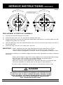
1
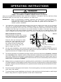
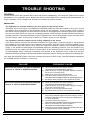
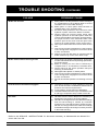
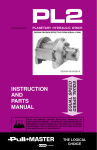
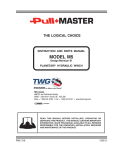
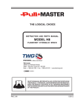
THE LOGICAL CHOICE
INSTRUCTION AND PARTS MANUAL
PL5 FREE FALL
PLANETARY HYDRAULIC WINCH
TWG Canada
LANTEC and Pullmaster Brands
19350 – 22nd Ave • Surrey, BC V3S 3S6
Voice: + 1 604-547-2100 • Fax: + 1 604-547-2147 • www.team-twg.com
READ THIS MANUAL BEFORE INSTALLING, OPERATING OR
SERVICING THIS PRODUCT. THIS MANUAL CONTAINS IMPORTANT
INFORMATION. MAKE THIS MANUAL AVAILABLE TO ALL PERSONS
RESPONSIBLE FOR THE OPERATION, INSTALLATION, SERVICING
AND MAINTENANCE OF THIS PRODUCT.
PMC 367
120612
Effective 2011/10/01
SUPERSEDES ALL PRIOR WARRANTIES
LIMITED WARRANTY
50130-0
Seller warrants that each article (whether Gear Drive Products, Brake Products and/or Winch Products, all of which are covered
hereunder) sold under this order shall at the time of shipment (i) conform to applicable specifications, and (ii) be free from
defects in material and workmanship during normal and ordinary use and service (the "Warranty").
Buyer's exclusive remedy and Seller's sole obligation under this Warranty shall be, at Seller's option, to repair or replace any
article or part thereof which has proven to be defective, or to refund the purchase price of such article or part thereof. Buyer
acknowledges that Buyer is knowledgeable concerning the articles covered by this Warranty and sold in connection therewith
which are being purchased, that Buyer has reviewed this Warranty and that the remedies provided hereunder are adequate
and acceptable to Buyer.
This Warranty shall expire one (1) year from the date the article is first shipped by Seller. Notice of claimed breach of this
Warranty must be given by Buyer to Seller within the applicable period. Such notice shall include an explanation of the claimed
warranty defect and proof of date of purchase of the article or part thereof for which warranty coverage is sought. No
allowances shall be made by Seller for any transportation, labor charges, parts, "in and out" costs, adjustments or repairs, or
any other work, unless such items are authorized in writing and in advance by Seller. Nor shall Seller have any obligation to
repair or replace items which by their nature are expendable.
If an article is claimed to be defective in material or workmanship, or not to conform to the applicable specifications, Seller will
either examine the article at Buyer's site or issue shipping instructions for return to Seller. This Warranty shall not extend to any
articles or parts thereof which have been installed, used, or serviced otherwise than in conformity with Seller's applicable
specifications, manuals, bulletins, or instructions, or which shall have been subjected to improper installation, operation, or
usage, misapplication, neglect, incorrect installation, overloading, or employment for other than normal and ordinary use and
service. This Warranty shall not apply to any article which has been repaired, altered or disassembled, or assembled by
personnel other than those of Seller. This Warranty shall not apply to any article upon which repairs or alterations have been
made (unless authorized in writing and in advance by Seller). This Warranty shall not apply to any articles or parts thereof
furnished by Seller to Buyer's specifications and/or furnished by Buyer or acquired from others at Buyer's request.
SELLER MAKES NO EXPRESS WARRANTIES AND NO IMPLIED WARRANTIES OF ANY KIND, OTHER THAN THE
WARRANTY EXPRESSLY SET FORTH ABOVE. SUCH WARRANTY IS EXCLUSIVE AND IS MADE AND ACCEPTED IN
LIEU OF ANY AND ALL OTHER WARRANTIES, EXPRESS OR IMPLIED, INCLUDING WITHOUT LIMITATION THE IMPLIED
WARRANTIES OF MERCHANTABILITY AND FITNESS FOR A PARTICULAR PURPOSE.
Buyer expressly agrees that Seller is not responsible to perform any work or investigation related in any way to torsional
vibration issues and is not responsible for the detection or remedy of Natural Frequency Vibration of the mechanical system in
which the unit is installed. Buyer acknowledges, understands and agrees that this Warranty does not cover failures of the unit
which result in any manner from the operation of the machine or unit at vibration frequencies at or near the natural frequency
vibration of the machine in such a way that damage may result. Buyer expressly agrees that Seller is not responsible for failure
damage or accelerated wear caused by machine or ambient vibration. Further, Buyer acknowledges and agrees that Buyer is
always solely responsible for determination and final approval of the “application factor” which may be used in Seller’s
calculations and this application factor is 1.0 unless otherwise stated in Seller’s quotation specifications.
The remedies for this Warranty shall be only those expressly set forth above, to the exclusion of any and all other remedies of
whatsoever kind. The limited remedies set forth above shall be deemed exclusive, even though they may fail their essential
purpose. No agreement varying or extending the foregoing Warranty, remedies, exclusions, or limitations shall be effective
unless in writing signed by an executive officer of Seller and Buyer. This Warranty is non-transferable. If a party who had
purchased articles from Buyer, or from persons in privity with Buyer, brings any action or proceeding against Seller for
remedies other than those set forth in this Warranty, Buyer agrees to defend Seller against the claims asserted in such action
or proceeding at Buyer’s expense, including the payment of attorneys’ fees and costs, and indemnify Seller and hold Seller
harmless of, from and against all such claims, actions, proceedings or judgments therein. Buyer also agrees to defend and
indemnify Seller of, from and against any loss, cost, damage, claim, debt or expenses, including attorneys’ fees, resulting from
any claims by Buyer or third parties to property or injury to persons resulting from faulty installation, repair or modification of the
article and misuse or negligent operation or use of the article, whether or not such damage to property or injury to persons may
be caused by defective material, workmanship, or construction.
ADVISORY: Winches and hoists are not approved for lifting or handling personnel or persons unless specifically approved in
writing from Seller for the specific intended application.
Under no circumstances shall Seller be liable (i) for any damage or loss to any property other than the warranted article or part
thereof, or (ii) for any special, indirect, incidental, or consequential damage or loss, even though such expenses, damages, or
losses may be foreseeable.
The foregoing limitations on Seller's liability in the event of breach of warranty shall also be the absolute limit of Seller's liability
in the event of Seller's negligence in manufacture, installation, or otherwise, with regard to the articles covered by this
Warranty, and at the expiration of the Warranty period as above stated, all such liabilities shall terminate. Buyer’s purchase of
any article(s) covered by this Warranty shall constitute acceptance of the terms and conditions hereof and shall be binding
upon Buyer and Buyer’s representatives, heirs and assigns. The laws of the Province of British Columbia shall govern Buyer’s
rights and responsibilities in regard to this Warranty and the transaction(s) subject thereto, and the Province of British Columbia
shall be the exclusive forum and jurisdiction for any action or proceedings brought by Buyer in connection herewith or any
dispute hereunder. If any of the terms and conditions contained within this Warranty are void, the remaining provisions thereof
are and shall remain valid and enforceable.
SAFETY RECOMMENDATIONS
Definition: Caution indicates a potentially
hazardous situation which, if not avoided may
result in minor or moderate injury.
DANGER
Definition: Warning indicates a potentially
hazardous situation which, if not avoided could
result in death or serious injury.
FAILURE TO COMPLY WITH THE FOLLOWING SAFETY
RECOMMENDATIONS AND LOCAL RULES AND
REGULATIONS WILL RESULT IN PROPERTY
DAMAGE, SEVERE INJURY OR DEATH.
Definition: Danger indicates a potentially
hazardous situation which, if not avoided will
result in death or serious injury.
PULLMASTER planetary hydraulic winches are made for hoisting and lowering loads and are to be operated by trained
and professional personnel. They are not designed for operations involving lifting or moving personnel. The winches
are powered by hydraulic power. The ropes / cables for hoisting operations are not supplied by PULLMASTER WINCH
CORPORATION. The winches are always assembled in an application, they do not function as an independent
machine and it is not allowed to use them as such.
elen
The winches are to be used within the specifications as listed in the manual under “SPECIFICATIONS”. Other use
as foreseen in the functional description of the hydraulic winch is not allowed without written permission from
PULLMASTER WINCH CORPORATION.
1.
Do not install, operate or service winch before
reading and understanding manufacturer's
instructions.
2.
The winch described herein is not designed
for operations involving lifting or moving personnel.
3.
Do not lift or carry loads over people.
18. Use only recommended hydraulic oil and gear
lubricant.
19. Keep hydraulic system clean and free from
contamination at all times.
20. Maintain winch and equipment in good operating
condition. Perform scheduled maintenance regularly.
4.
Do not exceed recommended operating
pressure (psi) and operating volume (gpm).
21. Keep hands clear when winding wire rope onto the
winch drum.
5.
Do not jerk the winch. Always smoothly
accelerate and decelerate load.
22.
Do not use the wire rope as a ground for welding.
6.
Do not operate a damaged, noisy or
malfunctioning winch.
23. Rig the winch carefully. Ensure that the wire rope
is properly anchored to the correct cable anchor slot at
the cable drum.
7.
Do not leave a load suspended for any
extended period of time.
24. Do not lift a load with a twisted, kinked or
damaged wire rope.
8.
25. Consult wire rope manufacturer for size, type and
maintenance of wire rope.elen
Never leave a suspended load unattended.
9.
Winch should be maintained and operated by
qualified personnel.
10. Inspect winch, rigging, mounting bolts and
hoses before each shift.
11. Warm-up equipment before operating winch,
particularly at low ambient temperatures.
12. Verify winch function by raising and lowering a
full test load to a safe height before each shift.
13.
Do not weld any part of the winch.
14. Verify gear lubrication and brake circulation
supply and return before operating winch.
15. Be sure of equipment stability before
operating winch.
16. Wear proper clothing to avoid entanglement in
rotating machinery.
17.
367
26. Maintain five wraps of wire rope on the cable
drum at all times.
27. In case of a power failure or breakdown leading to
an unexpected stop of the hydraulic power circuit,
stand clear of the area and the load being hoisted,
take the necessary precautions to prevent access to
area where the load is halted.
28. The noise level of the winch is 90 dBA measured
on a distance of 1.00 meter, 1.60 meters high. The
measuring equipment used was: Realistic #42-3019.
29.
Clean up any oil spillage immediately.
30. Wear proper clothing and personal protection
equipment such as, footwear, safety goggles and a
hard hat. Read manual first.
Always stand clear of the load.
PAGE 1
051117
DESCRIPTION OF THE MODEL PL5 WITH FREE FALL
GENERAL DESCRIPTION:
The PULLMASTER Model PL5 with free fall is a planetary hydraulic winch having equal speed in both
directions and the ability to lower a load FAST. The main components of this unit are:
✛
✛
✛
✛
✛
✛
✛
✛
✛
hydraulic gear motor
multi disc brake with static and dynamic function
over-running clutch
primary planet reduction
final planet reduction
brake housing
cable drum
free fall end housing
free fall clutch assembly
FUNCTION IN FORWARD ROTATION (HOISTING):
In forward rotation, the output torque and rpm of the hydraulic motor are transmitted to the sungear of
the primary planet reduction. The output of the primary reduction is transferred to the final sungear, which
is splined to the primary planet hub. The final planet assembly is locked in place by the free fall clutch
and does not rotate, so the rotation is transmitted to the cable drum by the final drive planet gears. In forward
rotation, or when a load is lifted, an over-running clutch, which connects the motor drive shaft to the
automatic brake assembly, permits free rotation of the sungear, without effecting the brake. Pressure
required to rotate the drum at full speed without load may vary up to 300 psi (21 bar). When the winch
rotation is stopped, the load on the cable drum causes the over-running clutch to lock and the maximum
load is held safely by the disc brake.
FUNCTION IN REVERSE ROTATION (LOWERING):
In reverse rotation, or when the winch is pressurized for lowering a load, pressure from the hydraulic motor
is channelled to the brake piston, causing the brake piston to release the multi-disc brake against a number
of brake springs. The pressure required to release the brake is 300 - 500 psi (21 - 34 bar) depending upon
load. The over-running clutch, connecting the motor drive shaft to the brake assembly, locks, causing the
brake discs to rotate between divider plates, which are engaged into the brake housing. If the load on
the cable drum tends to effect the lowering speed, the resulting pressure drop in the brake piston causes
friction between the brake discs and the divider plates. In this way, a completely smooth paying out speed
can be achieved in a stepless operation by modulation of the winch control valve handle. When the control
valve handle is returned to neutral position, pressure drops and the disc brake applies automatically. A
hydraulic counter-balance valve or holding valve is not required for smooth and positive operation of the
automatic brake.
During the lowering operation of the winch, the friction created by the brake discs results in heat. This heat
is dissipated by the circulation of hydraulic fluid through the brake housing, supplied internally through
the hydraulic motor. This circulation flow is internally drained to the return line flow through a check valve
arrangement inside the hydraulic motor. The circulation flow is supplied automatically by the hydraulic motor
when a load is lowered. If the pressure inside the brake housing is kept at or below 100 psi, generally there
is no need for a brake circulation return line. (See TYPICAL HYDRAULIC CIRCUITS.)
IMPORTANT:
367
Pressure in the brake housing must never exceed 100 psi (7 bar). Excessive brake housing
pressure will cause the safety valve, located on top of the motor, to leak. Brake housing
pressure can be gauged at the safety valve port.
PAGE 2
050906
DESCRIPTION OF THE MODEL PL5 WITH FREE FALL
WARNING
ALWAYS ENSURE COMPLIANCE WITH ANY NATIONAL OR LOCAL
SAFETY CODES AND REGULATIONS REGARDING THE USE OF FREE
FALL WINCHES PRIOR TO OPERATION OF THIS UNIT.
EMERGENCY FREE FALL:
The emergency free fall is used for a full release of a suspended load up to the maximum load capacity
of the PULLMASTER Model PL5 planetary winch with free fall. Upon activating the emergency free
fall function the load will drop and must be allowed to fall to its end travel without re-engagement.
DANGER
RE-ENGAGING FREE FALL CLUTCH WHILE LOAD IS DROPPING
CAUSES SHOCK LOADS AND WILL LEAD TO CABLE FAILURE,
PROPERTY DAMAGE, SEVERE INJURY OR DEATH. INTERLOCK
HYDRAULIC CONTROL TO PREVENT RE-ENGAGING FREE FALL
CLUTCH WHILE LOAD IS DROPPING.
FUNCTION OF THE EMERGENCY FREE FALL:
When the PULLMASTER Model PL5 planetary winch with free fall is actuated for emergency free fall,
hydraulic pressure is supplied to the clutch piston, compressing a series of springs to release the multidisc clutch. This effectively disconnects the cable drum from the gear train of the winch to drop the
suspended load. Minimum load 100 lbs (45 kg) is required to overcome the resistance in free fall mode.
IMPORTANT:
367
Pressure in the free fall end housing must never exceed 10 psi (.7 bar).
Free fall end housing pressure can be gauged at the circulation inlet port.
PAGE 3
050906
EXPLANATION OF MODEL CODING
PL 5 X - XX - XX - XX D - XXXX
BASIC UNIT SERIES
SIZE OF UNIT
REDUCTION RATIO
Only used for non-standard reduction ratios
TYPE OF BRAKE
-12
Automatic brake, counterclockwise hoisting, intravent
-13
Automatic brake, external brake release, counterclockwise
hoisting, intravent
-14
Automatic brake, external brake release, clockwise hoisting
intravent
-15
Automatic brake, clockwise hoisting, intravent
HYDRAULIC MOTOR
-210 Gear motor, 2.0 cubic inch displacement
(For optional motors refer to APPENDIX A)
DRUM SIZE
-1
7.38 inch drum diameter x 11.00 inch flange diameter x 6.56 inch
length (STANDARD)
(For optional drum sizes refer to APPENDIX A)
OPTIONS
D
Emergency free fall
SPECIFICATION NUMBER
Describes features not identified by preceding codes
NOTE:
367
Clockwise and counterclockwise drum rotation is the direction of rotation for pulling or hoisting,
established by looking at the hydraulic motor.
PAGE 4
050906
OPTIONS
CLOCKWISE ROTATION:
The drum rotation of the standard PULLMASTER Model PL5 planetary winch with free fall is counterclockwise
for hoisting, when looking at the hydraulic motor of the winch. Drum rotation for clockwise hoisting direction
is available as an option.
EXTERNAL BRAKE RELEASE:
PULLMASTER planetary winches can be supplied with an external brake release which permits release
of the automatic disc brake from an external pressure source.
DANGER
FAILURE TO PROPERLY VENT EXTERNAL BRAKE RELEASE PORT
WILL TRAP BRAKE PRESSURE AND ALLOW THE LOAD TO DROP,
CAUSING PROPERTY DAMAGE, SEVERE INJURY OR DEATH.
WINCHES SUPPLIED WITH EXTERNAL BRAKE RELEASE OPTION
MUST BE CONNECTED ACCORDING TO "TYPICAL HYDRAULIC CIRCUITS".
CABLE DRUM SIZES:
Aside from the standard drum sizes listed in APPENDIX A, the PULLMASTER Model PL5 planetary winch
with free fall can be supplied with optional drums to accommodate large wire rope storage capacity.
DRUM GROOVING:
Cable drums for the PULLMASTER Model PL5 planetary winch with free fall can be grooved. Where this
option is a requirement, it is necessary to state the size of wire rope which is to be used with the winch.
OPTIONAL GEAR SECTION FOR THE HYDRAULIC MOTOR:
The performance of the standard PULLMASTER Model PL5 planetary winch with free fall may be changed
by using a different displacement motor.
(See APPENDIX A for performance information.)
HYDRAULIC MOTORS FOR HIGH PRESSURE HYDRAULIC SYSTEMS:
The operating pressure of the PULLMASTER Model PL5 planetary winch with free fall and standard gear
motor is limited to 2100 psi (145 bar). For hydraulic systems operating with higher hydraulic pressure, the
winch can be supplied with a hydraulic piston motor which will provide for the same basic performance
in terms of line pull and line speed capacity.
(Contact the factory for this requirement.)
The PULLMASTER WINCH CORPORATION will consider other options for quantity requirements.
367
PAGE 5
050906
SPECIFICATIONS
Performance specifications are based on standard hydraulic motor, gear ratio and cable drum with 7/16
inch diameter wire rope. See APPENDIX A for performance of available options.
CABLE DRUM DIMENSIONS (STANDARD DRUM):
Barrel Diameter
Flange Diameter
Barrel Length
CABLE STORAGE CAPACITY:
Size of wire rope
1/4
5/16
3/8
7/16
1/2
in
in
in
in
in
MAXIMUM OPERATING PRESSURE:
MAXIMUM OPERATING VOLUME:
MINIMUM OPERATING VOLUME:
DRUM TORQUE AT MAXIMUM PRESSURE:
7.38 in
11.00 in
6.56 in
187 mm
279 mm
167 mm
348
218
157
110
100
106
67
48
34
31
ft
ft
ft
ft
ft
m
m
m
m
m
2100 psi
145 bar
24 (US) gpm
91 l/min
6 (US) gpm
23 l/min
17,578 lb-in
1986 Nm
DRUM RPM AT MAXIMUM VOLUME:
66 rpm
LINE PULL AT MAXIMUM PRESSURE:
Bare drum
Full drum
4500 lb
3328 lb
20.0 kN
14.8 kN
LINE SPEED AT MAXIMUM VOLUME:
Bare drum
Full drum
135 fpm
183 fpm
41 m/min
56 m/min
65 psi
4.5 bar
100 psi
7 bar
10 psi
0.7 bar
PERMISSIBLE SYSTEM BACK PRESSURE
AT MOTOR RETURN PORT:
PERMISSIBLE PRESSURE IN BRAKE HOUSING
(GAUGED AT SAFETY VALVE PORT):
PERMISSIBLE PRESSURE
AT FREE FALL CIRCULATION SUPPLY PORT:
LUBRICATING OIL:
Volume required (-1 drum):
Volume required (-6 drum):
0.3 (US) gal (1.1 litre)
0.5 (US) gal (1.9 litre)
Refer to RECOMMENDATIONS for viscosity and instructions.
367
PAGE 6
050906
PERFORMANCE GRAPHS
PG-PL5-C
LINE PULL VS. OIL PRESSURE:
LINE PULL - kN
0
3.3
6.7
10.0
13.3
16.7
20.0
145
2100
M
OIL PRESSURE - psi
RU
D
RE
BA
FU
1500
124
M
RU
D
LL
104
1200
83
900
62
600
41
300
21
OIL PRESSURE - bar
1800
0
0
0
750
1500
2250
3000
3750
4500
50
60
LINE PULL - lb
LINE SPEED VS. OIL VOLUME:
LINE SPEED - m/min
0
10
20
30
40
91
24
E
AR
DR
LL
DR
76
FU
B
16
61
12
45
8
30
4
15
OIL VOLUME - l/min
OIL VOLUME - (US)gpm
UM
UM
20
0
0
0
33
66
99
132
165
198
LINE SPEED - fpm
Performance graphs are based on standard hydraulic motor, gear ratio and cable drum with 7/16 inch
diameter rope.
367
PAGE 7
050906
TYPICAL HYDRAULIC CIRCUITS
HC-PL5-D-S1-A
PRESSURE
RELIEF VALVE
HYDRAULIC
PUMP
WINCH CONTROL
VALVE
(MOTOR SPOOL)
4-WAY SPRING
RETURN TO CENTER
800 PSI (55 BAR)
2.5 US GPM (9.5 L/MIN)
REQUIRED FOR MODELS
SUPPLIED WITH EXTERNAL
BRAKE RELEASE OPTION
FREEFALL CLUTCH
RELEASE 750 PSI (52 BAR)
FILTER
FREEFALL
CIRCULATION SUPPLY
2 US GPM (8L/MIN)
FREEFALL CIRCULATION RETURN (DIRECT TO RESERVOIR)
RESERVOIR
1.
TYPICAL HYDRAULIC CIRCUIT - STANDARD CONTROL VALVE
Refer to above hydraulic circuit for installations where the winch is controlled by an individual
control valve. Note that the valve must have a motor spool (both winch ports open to tank in
neutral position). A brake circulation return line is not required.
WINCH CONTROL
VALVE
(MOTOR SPOOL &
POWER BEYOND)
CONTROL VALVE STACK
2.
TYPICAL HYDRAULIC CIRCUIT - POWER BEYOND CONTROL VALVE
Refer to above hydraulic circuit when the winch control valve is used in a circuit containing
stacked valves controlling other functions, as occurs on hydraulic cranes and loaders.
The winch control valve must have a motor spool and power beyond feature. The
winch valve is shown upstream of the stacked control valves. If the winch control valve is
located downstream of the stacked control valves, the valve stack must have the power
beyond feature. A brake circulation return line is not required.
367
PAGE 8
050906
TYPICAL HYDRAULIC CIRCUITS
HC-PL5-D-S1-A
CONTROL VALVE STACK
BRAKE CIRCULATION RETURN
(MUST GO DIRECT
TO RESERVOIR)
WINCH CONTROL
VALVE
(CYLINDER SPOOL)
3. TYPICAL HYDRAULIC CIRCUIT - STACKED CONTROL VALVE
Refer to above hydraulic circuit when the winch control valve is one of several stacked control
valves and has a cylinder spool (winch ports blocked in neutral position). In this configuration,
the safety valve must be replaced with a circulation return line plumbed directly to the reservoir.
The brake circulation return line cannot be connected to a common return line.
IMPORTANT:
367
For proper function of the winch in any circuit, the return line back pressure
measured at the motor return port, the brake housing pressure measured at the
safety valve and the free fall end housing pressure measured at the circulation
inlet port must not exceed pressures per SPECIFICATIONS.
PAGE 9
050906
RECOMMENDATIONS
HYDRAULIC FLUID:
The hydraulic fluid selected for use with PULLMASTER
planetary winches should be a high grade, petroleum
based fluid with rust, oxidation and wear resistance.
Fluid cleanliness and operating viscosity are critical to
winch reliability, efficiency and service life.
For optimum performance, the recommended viscosity
range at operating temperature is 81 - 167 SUS (16 - 36
CS). For extreme operating conditions of short duration,
the maximum viscosity range of 58 - 4635 SUS (10 - 1000
CS) should not be exceeded.
The recommended hydraulic fluid temperature operating
range is 80 - 150F (27 - 66C). For extreme operating
conditions of short duration, the maximum temperature
range of -5 - 180F (-21 - 82C) should not be exceeded.
LUBRICATION:
The winch gear train requires oil bath lubrication. The
winch is shipped from the factory without lubricating oil.
IMPORTANT: ADD LUBRICATING OIL THROUGH THE
CABLE DRUM FILL PORT BEFORE
RUNNING WINCH.
Refer to INSTALLATION DIMENSIONS for location of
lubricating oil fill port. For normal operating temperature
use SAE 90 lubricating oil in the cable drum: 0.3 gallon
(1.2 liters) for -1 drum and 0.5 gallon (2 liters) for -6 drum.
Consult lubricating oil supplier or factory for temperatures
beyond normal operating range.
HYDRAULIC PUMP:
For maximum performance of the PULLMASTER planetary
winch the hydraulic pump must supply the maximum flow
of hydraulic fluid at the hydraulic pressure stated in
SPECIFICATIONS.
EMERGENCY FREE FALL CONTROL VALVE:
A two-position, three-way, detented valve is required to
actuate emergency free fall. Emergency free fall is used
to fully release a load up to the maximum capacity of the
winch. The valve is not required to meter oil supply. In
neutral position, the free fall clutch release port must be
vented to reservoir.
DANGER
HYDRAULIC CONTROL VALVE:
A standard control valve used for operating PULLMASTER
planetary winches must have a four-way, spring return to
neutral feature, which provides for open flow from the
pressure ports of the winch to the reservoir in neutral
position of the control (motor spool). It is important to point
out that good speed control, especially when lowering a
load, depends on the "metering" characteristics of the
control valve. The better the oil flow is "metered", the
better will be the speed control.
HYDRAULIC PRESSURE RELIEF:
The hydraulic circuit for the PULLMASTER planetary
winch requires a pressure relief set at the operating
pressure (see SPECIFICATIONS). Usually, a pressure
relief is part of the hydraulic control valve. Where this
is not the case, a separate pressure relief valve must be
installed and set at the recommended maximum pressure.
HYDRAULIC RESERVOIR:
It is recommended that the hydraulic reservoir has
sufficient capacity to provide good heat dissipation in
order to prevent over-heating of the hydraulic fluid. The
hydraulic reservoir should be made from clean and scalefree material to prevent contamination of the hydraulic
fluid. In order to prevent air from being mixed with the
hydraulic fluid, the reservoir should have an over-flow
baffle separating the return lines from the suction line and
all return lines should enter the reservoir below the fluid
level. The reservoir should be mounted close to and above
the hydraulic pump in a location which provides for free
air circulation around the reservoir.
HYDRAULIC FILTER:
Consult hydraulic component manufacturer for
recommendation. Generally, 5 to 10 micron filters are
acceptable. In order to prevent accidental stoppage of
the return line flow, the filter should have a by-pass
feature.
HYDRAULIC HOSES:
The following hydraulic hose with suitable fittings is
recommended for the PULLMASTER Model PL5 planetary
winch with free fall.
Pressure lines:
Circulation return line:
Circulation supply line:
Free fall release line:
SAE 100R2-14 or better
SAE 100R6-8 or better
SAE 100R6-4 or better
SAE 100R2-4 or better
USE OF AN E STOP:
RE-ENGAGING FREE FALL CLUTCH WHILE
LOAD IS DROPPING CAUSES SHOCK LOADS
AND WILL LEAD TO CABLE FAILURE,
PROPERTY DAMAGE, SEVERE INJURY OR
DEATH. INTERLOCK HYDRAULIC CONTROL
TO PREVENT RE-ENGAGING FREE FALL
CLUTCH WHILE LOAD IS DROPPING.
367
PAGE 10
(FOR EUROPEAN MACHINERY DIRECTIVE APPLICATIONS)
The use of an E stop (emergency) is mandatory in the
controls circuit. The E stop is to be placed in the operators
control panel. The E stop has to be designed and placed
in line with EN 60204 and EN 418.
050906
INSTALLATION INSTRUCTIONS
DANGER
FAILURE TO FOLLOW INSTALLATION INSTRUCTIONS WILL RESULT IN
PROPERTY DAMAGE, SEVERE INJURY OR DEATH.
The initial installation or mounting of a PULLMASTER planetary winch is critically important for proper
operation and performance. If the winch is mounted to an uneven surface, the centre line of the unit
can be distorted to a point where the winch will not operate in either direction. It is therefore very
important that the following instructions are observed when a PULLMASTER planetary winch is
installed:
1)
Make certain that the mounting platform is sufficiently strong in order to avoid deflection when
a load is lifted.
2)
Set the winch on the mounting platform and check for surface contact on all mounting pads of
the winch.
3)
If there is a space between the mounting surface and one of the mounting pads, the mounting
surface is not even and the space below the mounting pad must be shimmed. If this condition
exists, proceed as follows:
a)
Install mounting bolts snug tight on the three mounting pads which are in contact with the
mounting surface. For mounting bolt size and grade, see INSTALLATION DIMENSIONS.
b)
Measure the space underneath the fourth mounting pad with a feeler gauge and use shim
stock of equivalent thickness in the space between the mounting pad and the mounting
surface.
c)
Only after this procedure, should the fourth mounting bolt be installed. Tighten all four bolts
as per BOLT TORQUE CHART at back of manual.
4)
Fill the drum with lubricating oil. Refer to RECOMMENDATIONS (page 10) for oil volume required.
Refer to INSTALLATION DIMENSIONS for location of fill port.
5)
Use recommended circuit components and hydraulic hoses.
6)
The circulation return line of the free fall housing should be plumbed in such a manner that the
free fall housing remains full of oil at all time. Connect the return line directly to reservoir. Do not
connect to a common return line.
7)
When required, the winch drain line must be connected directly to the reservoir. Do not connect
to a common return line.
IMPORTANT: Excessive pressure at brake housing will damage the winch motor or oil seals. Never
plug safety valve port.
8)
Before operating the winch with a load, verify that approximately 1.5 (US) gpm (6 l/min) hydraulic
fluid is circulating through the brake assembly by removing the safety valve and checking flow
when the winch is run in the lowering direction. Verify that hydraulic fluid is circulating though the
free fall clutch assembly by checking the flow at the circulation return line.
9)
Bleed the air out of the free fall control circuit by loosening the connection at the free fall release
port on the winch. With no load on the cable drum, operate the free fall control valve, letting all
air escape, then re-tighten the connection at the release port.
367
PAGE 11
050906
OPERATING INSTRUCTIONS
DANGER
FAILURE TO FOLLOW OPERATING INSTRUCTIONS WILL
RESULT IN PROPERTY DAMAGE, SEVERE INJURY OR DEATH.
After the PULLMASTER planetary winch has been installed in accordance with the INSTALLATION
INSTRUCTIONS, the wire rope can be fastened to the cable drum.
IMPORTANT:
1)
Refer to manufacturer’s handling, inspection and maintenance recommendations to
avoid potential accidents. For selection of ropes, etc. please check following product
standards: DIN 15020, prEN818-1/9, prEN 1492-1/2, prEN 1677-1/3 and other
relevant product standards.
The cable drum of the PULLMASTER planetary winch has two cable anchor slots, one for clockwise
and one for counterclockwise hoisting. Standard rotation for hoisting is counterclockwise when
looking at the hydraulic motor of the unit. It is critical to select the cable anchor slot which will permit
winding of the wire rope on the drum in the correct direction of rotation. If the wire rope is wound
on the cable drum in the wrong direction of rotation, the winch will have no braking capacity. Each
winch is shipped from the factory with a label on the drum, indicating the correct cable anchor slot.
SI1013
WIRE ROPE INSTALLATION
Counterclockwise hoisting winch shown.
(Use cable anchor slot on opposite side
of drum for clockwise hoisting winch.)
Feed the wire rope through the cable
anchor slot. Loop rope back into slot
as shown. Insert cable anchor into
slot, small end first and long side
nearest the drum flange. Pull rope
tight to wedge rope in slot.
CABLE ANCHOR SLOT
CABLE ANCHOR
2)
On wire rope installation, care must be taken that the wire rope is wrapped completely around
the cable anchor and properly pulled into the cable anchor slot in the cable drum. The cable drum
requires minimum of 5 wraps of wire rope for safety.
3)
The winch operation is controlled by a single control valve lever which has a forward, a reverse
and a neutral position. Speed control in either direction is obtained by modulation of the control
valve lever. Maximum line speed in either direction is obtained when the control valve lever is
moved as far as it can go. The disc brake of the winch will come on automatically when the winch
control lever is returned to neutral.
4)
Always warm up equipment prior to operating winch, particularly in low ambient temperature.
Circulate hydraulic oil through the winch control valve for several minutes to warm the hydraulic
systems. To prime the winch with warm oil, operate the winch at slow speed, forward and reverse,
several times.
5)
Prevent corrosion damage to winch interior. If not used regularly, run winch up and down at least
once every two weeks.
6)
To ensure proper winch installation and function, raise and lower a full test load to a safe height
before using winch for regular operation at the start of each shaft.
367
PAGE 12
051117
OPERATING INSTRUCTIONS
7)
Shift the emergency free fall control valve to pressurize the free fall clutch release port, effectively
disconnecting the cable drum from the gear train and dropping the load. Free fall speed depends
on size of the load. The minimum load that will overcome the resistance in free fall mode is
approximately 100 lb (45 kg).
DANGER
RE-ENGAGING FREE FALL CLUTCH WHILE LOAD IS DROPPING
CAUSES SHOCK LOADS AND WILL LEAD TO CABLE FAILURE,
PROPERTY DAMAGE, SEVERE INJURY OR DEATH. INTERLOCK
HYDRAULIC CONTROL TO PREVENT RE-ENGAGING
FREE FALL CLUTCH WHILE LOAD IS DROPPING.
If, after a new installation, the winch does not function properly, refer to the TROUBLESHOOTING
section of this manual.
367
PAGE 13
050906
TROUBLE SHOOTING
GENERAL:
In most cases, when the hydraulic winch does not perform satisfactorily, the cause for malfunction is found
somewhere in the hydraulic circuit. Before the winch is removed from its mounting and disassembled, all
of the hydraulic circuit components should be checked for proper function.
IMPORTANT:
The hydraulic oil volume relates to the line speed or rpm of the winch.
Therefore, if the winch does not produce the specified maximum rated line speed or drum rpm, a loss
of hydraulic flow somewhere in the hydraulic circuit can be analysed. If this condition exists, install a
flow meter into the hydraulic circuit to check the volume of oil supplied to the pressure port of the hydraulic
winch motor when the winch control is completely opened. The flow meter should indicate the maximum
operating volume. If this test indicates a loss of hydraulic flow, check the hydraulic pump, the relief valve
and the control valve. If the pump is driven by V-belts, check for belt slippage.
The hydraulic pressure relates to the pulling capacity of the winch.
If the winch will not produce the specified maximum line pull, install a pressure gauge in the pressure
line leading to the hoisting port on the hydraulic winch motor. Stall the winch to prevent rotation of the
drum and then open the control valve. Check the hydraulic pressure reading of the installed pressure
gauge. If the pressure reads below the specified maximum operating pressure, look for trouble in the
hydraulic pump, the relief valve and the control valve. If the hydraulic pump is driven by V-belts, check
for belt slippage. When checking oil pressure and volume in the hydraulic circuit, make sure that the
hydraulic reservoir is filled to the top level and the hydraulic pump is running at maximum operating rpm.
Only after the hydraulic system has been checked and found to be in order, use the following indications
for probable causes of failure in the winch:
FAILURE
PROBABLE CAUSE
Winch will not produce line pull at maximum
pressure as listed in SPECIFICATIONS.
a)
b)
c)
d)
e)
Winch will not produce line speed at maximum
volume as listed in SPECIFICATIONS.
a)
b)
c)
d)
Winch will not reverse.
a)
b)
c)
d)
367
PAGE 14
Winch is mounted to an uneven surface.
(See INSTALLATION INSTRUCTIONS.)
Cable sheaves or block purchase operated with the
winch are not turning freely.
Damage or wear in the hydraulic motor.
The relief valve pressure may be set too low.
(See SPECIFICATIONS for maximum operating pressure.)
Excessive back pressure in the hydraulic system.
Winch is mounted to an uneven surface.
(See INSTALLATION INSTRUCTIONS.)
Cable sheaves or block purchase operated with the
winch are not turning freely.
Damage or wear in the hydraulic motor.
Excessive back pressure in the hydraulic system.
Leakage out of the brake piston prevents the disc brake
from being released against the brake springs. This is
caused by damage to the O-rings on the brake piston
or connecting tube.
Insufficient hydraulic pressure.
(See SPECIFICATIONS for minimum operating pressure.)
Winch is mounted to an uneven surface.
(See INSTALLATION INSTRUCTIONS.)
Hydraulic pressure is not reaching the brake piston due
to plugged brake release passage.
050906
TROUBLE SHOOTING CONTINUED
FAILURE
Brake will not hold.
PROBABLE CAUSE
a)
b)
c)
d)
e)
f)
g)
Brake vibrates when lowering a load.
a)
b)
c)
d)
e)
f)
Free fall clutch cannot be disengaged.
a)
b)
c)
Oil leaks.
a)
b)
Brake plates or divider plates have been damaged
by contamination in the hydraulic fluid or lack of
circulation flow in the brake housing.
Brake piston or clutch piston seize because of
contamination in the hydraulic fluid.
Excessive back pressure in the return line of the
hydraulic system causes the brake to release.
Control valve has incorrect spool which traps
hydraulic pressure in the brake piston when the
control valve handle is returned to neutral position.
For proper function of the automatic brake, both
pressure ports of the winch must be open to the
reservoir in neutral position of the control valve.
Wire rope is fastened to the incorrect cable anchor
slot.
Over-running clutch is damaged or surface where
over-running clutch engages on motor drive shaft
is worn or indented.
Failure to vent free fall clutch or optional external
brake release may cause winch load to slip.
Pump does not supply sufficient flow. Pump rpm
must be maintained at normal operating speed when
a load is lowered.
Brake is running too hot. This is caused by a
complete lack of, or insufficient, circulation flow.
Control valve for the winch operation has poor
metering characteristics.
Damaged brake plates or divider plates.
Over-running clutch is damaged or surface where
over-running clutch engages on motor drive shaft
is worn or indented.
Air has mixed with hydraulic oil resulting in foamy
oil.
Insufficient pressure or flow supplied to free fall
port. Check TYPICAL HYDRAULIC CIRCUITS for
pressure and volume requirements.
O-ring seals in clutch piston are damaged.
Insufficient load on the wire rope. A minimum of 100
lb (45 kg) is required to drop a load in free fall.
Oil leaks from the motor adaptor are caused by a
damaged O-ring seal on the motor adaptor.
Oil leaks occurring between the cable drum flange
and free fall housing is caused by excessive
pressure in the free fall housing or brake housing.
Oil leak occurring between the cable drum flange
and brake housing is caused by excessive pressure
in the brake housing.
Refer to the SERVICE INSTRUCTIONS if it becomes necessary to disassemble the Model PL5
winch with free fall.
367
PAGE 15
050906
SERVICE INSTRUCTIONS
GENERAL:
Before disassembling the PULLMASTER Model PL5 planetary winch with free fall, read and understand the following
instructions.
Replace expendable parts such as O-rings and oil seals when reassembling the winch. Have a winch seal kit (Part
No. 23418) on hand before the unit is disassembled. If motor is to be serviced, have on a hand motor seal kit (Part
No. 24227).
NOTE: Backup washers may be included with seal kit. Install with oil seals as per instructions. If not present
in seal kit, the oil seals supplied do not require backup washers.
Disconnect all hydraulic hoses, remove the winch from its mounting and relocate to a clean working area, similar
to one used for service work on any other hydraulic component. Special tools are not required to service the winch.
Adjustments and calibrations are not required.
All parts, as they are removed from the winch assembly, should be inspected for wear and damage. Worn or damaged
parts must be replaced. Thoroughly clean parts before reassembly. Do not use solvent to clean the brake friction
plates. During reassembly, lubricate all O-rings and oil seals with grease before installation.
The following SERVICE INSTRUCTIONS refer to part descriptions and item numbers which appear in the group
drawings.
DISASSEMBLY
REMOVAL OF FREE FALL ASSEMBLY:
If the brake, primary or final drives require service, or if a general inspection overhaul is required, proceed to
REMOVAL OF HYDRAULIC MOTOR ASSEMBLY. If specific service is required to correct a malfunction at the free
fall end, remove the free fall assembly as follows:
1)
Remove pipe plug, item 101, from free fall end housing, item 240, to drain lubricating oil from free fall end housing.
2)
With winch sitting flat on its mounting pads, remove four capscrews, item 555, and lockwashers, item 553,
which connect free fall housing, item 200, to tie bars, item 556.
3)
Support cable drum, item 500, and withdraw free fall end housing, item 240, until spline of connecting shaft,
item 220, is clear of cable drum.
4)
Remove pipe plug, item 101, from free fall end housing, item 240, to drain oil from free fall assembly interior.
5)
Stand free fall assembly on its end, with connecting shaft, item 220, vertical.
6)
Proceed to DISASSEMBLY OF FREE FALL ASSEMBLY.
REMOVAL OF HYDRAULIC MOTOR ASSEMBLY:
1)
Before removing hydraulic motor, refer to page 22 drawing # SI1043 and tick mark the position of the hydraulic
motor to facilitate reassembly.
2)
Remove four capscrews, item 931, and lockwashers, item 933, from the motor adaptor, item 900. Brake springs,
item 752, apply pressure against inside of motor adaptor, therefore it is recommended that capscrews are
unscrewed, one turn at a time, until spring pressure has been released. The complete motor assembly, including
motor adaptor, can now be removed from brake housing assembly.
3)
Remove and discard two O-rings, item 801 and item 707. (O-ring, item 801, seals pressure transfer hole for
automatic brake release and is situated on flange of brake housing.)
DISASSEMBLY OF HYDRAULIC MOTOR ASSEMBLY:
If service or repair work requires access to interior of brake housing, hydraulic motor should not be disassembled.
If problem has been analysed to be in hydraulic motor, proceed with disassembly as follows:
1)
367
Remove four hex capscrews, item 951, together with lockwashers, item 953, from motor assembly.
PAGE 16
050906
SERVICE INSTRUCTIONS CONTINUED
IMPORTANT:
Failure to exercise care when removing motor port end cover or gear housing could permanently
damage machined surfaces of motor components. Take care not to damage machined surfaces of
motor components at disassembly.
2)
Remove port end cover, item 871, from gear housing, item 860.
3)
Remove gear set, item 881 and item 882 and thrust blocks, item 885.
4)
Remove and discard channel seals, item 887 and item 888 and backup seals, item 897.
5)
Carefully pry gear housing, item 860, off of motor adaptor, item 900. Dowel pins, item 865, may stay in gear housing.
6)
Discard section seals, item 869.
Section seals, channel seals and backup seals in hydraulic motor assembly are not part of winch seal kit. Seal kit
for hydraulic motor can be ordered from factory under Part No. 24227.
DISASSEMBLY OF BRAKE HOUSING ASSEMBLY:
Disassemble brake housing assembly as follows:
1)
Remove ten brake springs, item 752. Examine springs for damage and measure overall length. Overall spring
length should be 1.25 inch. Springs measuring less than 1.19 inch should be replaced.
2)
Pull brake piston, item 750, out of brake housing, item 700.
3)
Remove and discard O-rings, item 751 and 753.
4)
Thoroughly inspect brake piston outer diameters and brake housing inner bores for scoring caused by hydraulic
fluid contamination. Minor surface damage may be repaired by polishing with a fine emery cloth.
5)
Remove circlip, item 727, from primary sungear, item 440. Remove brake hub, item 720, sprag clutch, item 723,
and sprag clutch aligners, item 722, from primary sungear.
DANGER
DAMAGED FRICTION OR DIVIDER PLATES WILL REDUCE BRAKING CAPACITY AND ALLOW THE
LOAD TO DROP, CAUSING PROPERTY DAMAGE, SEVERE INJURY OR DEATH. SOLVENT MAY
DAMAGE THE FRICTION PLATES. DO NOT USE SOLVENT TO CLEAN THE FRICTION
PLATES. PERFORM THOROUGH INSPECTION AND, IF NECESSARY,
REPLACE FRICTION AND DIVIDER PLATES AS A SET.
6)
Remove five friction plates, item 716, and six divider plates, item 713, and inspect for damage or wear. Plates
should be flat and smooth. Plates should not show heat discoloration. Paper material on friction plates should
be intact and grooved. If any damage is detected, replace friction and divider plates as a set (winches may contain
optional metallic friction plates).
7)
Remove brake spacer, item 712.
DISASSEMBLY OF PRIMARY DRIVE:
If the primary drive requires service or repair, disassemble as follows:
1)
Remove pipe plug, item 503, from cable drum, item 500, to drain lubricating oil from the winch interior.
2)
Remove four remaining capscrews, item 555, and lockwashers, item 553. Remove two tie bars, item 556. Stand
winch upright.
3)
Remove six capscrews, item 537, and lockwashers, item 541, through access opening in brake housing. Lift brake
housing with bearing flange out of cable drum, item 500 (bearing flange may stay in the cable drum). Remove
and discard O-ring, item 539.
4)
Remove circlip, item 719, from primary sungear, item 440.
5)
Remove primary sungear, item 440, from brake housing, item 700.
367
PAGE 17
050906
SERVICE INSTRUCTIONS CONTINUED
DANGER
MINOR SURFACE DEFECTS WHERE THE OVER-RUNNING CLUTCH ENGAGES THE MOTOR DRIVE
SHAFT WILL RESULT IN BRAKE FAILURE AND ALLOW THE LOAD TO DROP, CAUSING PROPERTY
DAMAGE, SEVERE INJURY OR DEATH. THOROUGHLY INSPECT THIS AREA AND, IF NECESSARY,
REPLACE PRIMARY SUNGEAR, SPRAG CLUTCH AND BRAKE HUB ASSEMBLY AS A SET.
6)
Thoroughly inspect primary sungear, item 440, and brake hub, item 720, particularly surfaces where sprag clutch,
item 723, engages.
7)
If any indentation or surface damage is detected, replace brake hub, sprag clutch and primary sungear as a set.
8)
Remove two thrust washers, item 737, and thrust bearing, item 739. Inspect parts and replace if damaged.
9)
Remove and discard oil seal, item 711, and backup washer, item 710.
10)
Remove primary planet hub assembly with final sungear, item 340, from cable drum.
11)
Inspect planet hub stopper, item 402, for damage or wear and replace if less than .09 inch thick.
12)
Inspect three primary planet gears, item 420, for damage or wear. If it is necessary to remove planet gears,
remove circlip, item 411, and press planet pin, item 410, out of planet hub, item 400. Inspect needle bearing,
item 423, and two thrust washers, item 421, and replace if damaged or worn.
13)
Remove final sungear, item 340, with circlip, item 341, and sungear stopper, item 344. Inspect stopper for damage
or wear. If stopper is worn more than .03 inch below face of sungear, stopper should be replaced.
14)
Inspect planet hub stopper, item 704, for damage or wear and replace if less than .09 inch thick.
15)
Pull bearing flange, item 530, and ball bearing, item 533, off of brake housing.
16)
Remove circlip, item 535. Push ball bearing, item 533, out of bearing flange. Inspect and replace if damaged.
17)
Remove and discard oil seal, item 531.
DISASSEMBLY OF FINAL DRIVE:
If final drive requires service or repair, disassemble as follows:
1)
Remove final planet hub assembly from cable drum.
2)
Inspect three final planet gears, item 320, for damage or wear. If it is necessary to remove planet gears, remove
circlip, item 311, and press planet pin, item 310, out of final planet hub, item 300. Inspect 20 loose rollers, item
323, and two thrust washers, item 321, and replace if damaged.
Winches with optional -6 drum only:
2a) Remove coupling, item 520, from connecting shaft spline, item 220.
3)
Remove cable drum, item 500, from connecting shaft, item 220.
4)
Remove circlip, item 513. Push ball bearing, item 507, out of cable drum. Inspect and replace if damaged.
5)
Remove and discard oil seal, item 505.
6)
Inspect cable drum gear teeth for damage or wear.
DISASSEMBLY OF FREE FALL ASSEMBLY:
If service or repair is required on free fall assembly, disassemble as follows:
1)
Allow free fall springs, item 232, to expand safely by unscrewing capscrews, item 209, one turn at a time.
2)
Remove free fall housing, item 200, together with connecting shaft, item 220.
3)
Remove circlip, item 228, and pull connecting shaft, item 220, out of free fall housing bearing, item 507.
4)
Remove and discard O-ring, item 213.
5)
Remove circlip, item 513. Push ball bearing, item 507, out of free fall housing. Inspect and replace if damaged.
367
PAGE 18
050906
SERVICE INSTRUCTIONS CONTINUED
6)
Remove and discard oil seal, item 505.
7)
Remove 22 free fall springs, item 232. Examine springs for damage and measure overall length. Overall spring
length should be 1.79 inch. Springs measuring less than 1.73 inch should be replaced.
8)
Pull free fall clutch piston, item 230, from free fall end housing, item 240, using two 3/8 NC threaded puller holes.
9)
Remove and discard O-ring, item 231 and 233.
10)
Thoroughly inspect free fall clutch piston outer diameters and free fall end housing inner bores for scoring caused
by hydraulic fluid contamination. Minor surface damage may be repaired by polishing with a fine emery cloth.
11)
Pull clutch hub, item 226, out of free fall end housing.
DANGER
DAMAGED FRICTION OR DIVIDER PLATES WILL REDUCE CLUTCHING CAPACITY AND
ALLOW THE LOAD TO DROP, CAUSING PROPERTY DAMAGE, SEVERE INJURY OR DEATH.
SOLVENT MAY DAMAGE THE FRICTION PLATES. DO NOT USE SOLVENT TO
CLEAN THE FRICTION PLATES. PERFORM THOROUGH INSPECTION AND,
IF NECESSARY, REPLACE FRICTION AND DIVIDER PLATES AS A SET.
12) Remove nine divider plates, item 204, and eight friction plates, item 206, and inspect for damage
or wear. Plates should be flat and smooth. Plates should not show heat discolouration. Paper material
on friction plates should be intact and grooved. If any damage is detected, replace friction and divider
plates as a set.
13) Remove clutch spacer, item 202.
14) Pull ball bearing, item 215, out of free fall end housing. Inspect and replace if damaged.
REASSEMBLY
Thoroughly clean all parts. Use only new, well-greased O-rings and oil seals. Unless otherwise specified,
torque fasteners per BOLT TORQUE CHART.
REASSEMBLY OF FREE FALL ASSEMBLY:
Reassemble free fall assembly by reversing the disassembly procedure.
1)
Press ball bearing, item 215, into free fall end housing, item 240.
2)
Install clutch hub, item 226, into free fall end housing.
DANGER
INCORRECT ASSEMBLY OF THE FRICTION PLATE AND DIVIDER PLATE STACK WILL
REDUCE CLUTCHING CAPACITY AND ALLOW THE LOAD TO DROP, CAUSING PROPERTY
DAMAGE, SEVERE INJURY OR DEATH. REASSEMBLE PER INSTRUCTIONS.
3)
Install clutch spacer, item 202, into free fall end housing. Starting and finishing with a divider plate,
alternately install nine divider plates, item 204, and eight friction plates, item 206.
4)
Install new, well greased O-rings, items 231 and 233, into clutch piston glands, item 230. Carefully
install clutch piston into free fall end housing.
5)
Install 22 free fall springs, item 232.
6)
Press new, well-greased oil seal, item 505, into free fall housing, item 200.
7)
Press ball bearing, item 507, into free fall housing and secure with circlip, item 513.
8)
Push connecting shaft, item 220, through free fall housing bearing. Install circlip, item 228.
367
PAGE 19
050906
SERVICE INSTRUCTIONS CONTINUED
9)
Install new, well-greased O-ring, item 213, into free fall housing groove.
10)
Position free fall housing, item 200, over free fall end housing, item 240. Tighten six capscrews, item 209, with
lockwashers, item 211, one turn at a time to evenly compress springs.
11)
If a specific malfunction at the free fall end has been serviced and the rest of the winch is intact, proceed to
REPLACEMENT OF FREE FALL ASSEMBLY. If the winch has been disassembled, proceed to REASSEMBLY
OF FINAL DRIVE.
REASSEMBLY OF FINAL DRIVE:
Reassemble final drive by reversing the disassembly procedure.
1)
Press new, well-greased oil seal, item 505, into cable drum, item 500.
2)
Press ball bearing, item 507, into cable drum and secure with circlip, item 513.
3)
Install cable drum, item 500, onto connecting shaft, item 220.
Winches with optional -6 drum only:
3a) Replace coupling, item 520, on connecting shaft spline.
4)
Reassemble final planet hub assembly. Use grease to temporarily hold 20 loose rollers, item 323, in bore of planet
gear, item 320. Position thrust washers, item 321, on either side of planet gear and press planet pin, item 310,
into final planet hub, item 300. Retain with circlip, item 311.
5)
Insert final planet hub assembly into cable drum. Ensure that planet hub spline is fully engaged.
REASSEMBLY OF PRIMARY DRIVE:
Reassemble primary drive by reversing the disassembly procedure.
1)
Press new, well-greased oil seal, item 531, into bearing flange, item 530. Press ball bearing, item 533, into bearing
flange and secure with circlip, item 535. Press bearing flange assembly onto brake housing hub.
2)
Verify planet hub stopper, item 704, is installed on brake housing hub.
3)
Verify sungear stopper, item 344, and circlip, item 341, are installed on final sungear, item 340.
4)
Install final sungear into primary planet hub, item 400.
5)
Reassemble primary planet hub assembly. Press needle bearing, item 423, into planet gear, item 420. Position
thrust washer, item 421, on either side of planet gear and press planet pin, item 410, into primary planet hub,
item 400. Retain with circlip, item 411.
6)
Verify planet hub stopper, item 402, is installed on planet hub.
7)
Insert primary planet hub assembly into cable drum. Ensure that final sungear, item 340, is fully engaged with
final planet gears, item 320.
8)
Press new, well-greased oil seal, item 711, and backup washer, item 710, into brake housing bore, item 700.
9)
Install thrust bearing, item 739, (with thrust washer, item 737, on either side) against oil seal, item 711.
10)
Insert primary sungear, item 440, through brake housing bore, item 700, and fasten with circlip, item 719.
11)
Install new, well-greased O-ring, item 539, onto bearing flange, item 530. Insert bearing flange into cable drum
opening and fasten with six capscrews, item 537, and lockwashers, item 541. Slide brake housing, item 700,
into bearing flange, turning primary sungear, item 440, to engage primary planet gears, item 420.
12) Use eight capscrews, item 555, and lockwashers, item 553, to secure tie bars, item 556.
13) Install pipe plug, item 503, into cable drum.
REASSEMBLY OF BRAKE HOUSING ASSEMBLY:
Reassemble brake housing assembly by reversing the disassembly procedure.
1)
367
Install sprag clutch, item 723, into bore of brake hub, item 720, and position sprag clutch aligners, item 722,
on either side of brake hub. Carefully slide brake hub assembly onto primary sungear, item 440. Secure with
circlip, item 727.
PAGE 20
050906
SERVICE INSTRUCTIONS CONTINUED
IMPORTANT: For proper brake function, verify that brake hub rotation is correct. When viewed from
the motor end, the primary sungear of a counterclockwise hoisting winch must turn
freely clockwise and lock in the counterclockwise direction.
DANGER
INCORRECT ASSEMBLY OF THE FRICTION PLATE AND DIVIDER PLATE STACK WILL
REDUCE BRAKING CAPACITY AND ALLOW THE LOAD TO DROP, CAUSING PROPERTY
DAMAGE, SEVERE INJURY OR DEATH. REASSEMBLE PER INSTRUCTIONS.
2)
Install brake spacer, item 712, into brake housing, item 700.
NOTE: For PL5 free fall with -213 motor: Refer to 3a)
3)
Starting and finishing with a divider plate, alternately install six divider plates, item 713, and five friction
plates, item 716.
3a) Starting with two divider plates, item 713, two friction plates, item 716, repeat two divider plates, two
friction plates, one divider plate, one friction plate ending with one divider plate, item 713.
4)
Install new, well-greased O-rings, items 751 and 753, into piston, item 750. Carefully install brake
piston in brake housing, item 700.
5)
Install ten brake springs, item 752.
REASSEMBLY OF HYDRAULIC MOTOR:
If the hydraulic motor was disassembled, the following procedure should be followed for reassembly:
1)
Clean all parts thoroughly before reassembly and apply grease liberally to all seals. Use only new
seals (seal kit Part No. 24227) for hydraulic motor.
2)
Install new, well-greased rubber channel seal, item 887 and item 888 into thrust block, item 885,
so that protrusions in seal match recesses in block. Install new backup seal, item 897, over top of
channel seal, leaving flat side of backup seal flush with surface of thrust block. Insert thrust block,
item 885, into the gear housing, making sure seals are facing away from gear set.
3)
Install well-greased section seal, item 869, on gear housing, item 860. Install gear housing together
with seal
section, onto motor adaptor, item 900, lined up on two dowel pins. Tap on tight using a soft headed
hammer.
4)
Install gear set, item 881 and item 882 in gear housing. (External spline end of gear goes into bore
of motor adaptor.)
5)
Insert other thrust block, complete with backup and channel seals, making sure seals are facing away
from gear set. Install a well-greased seal section, item 869, on gear housing.
6)
Install port end cover, item 870, onto gear housing and lightly torque four hex capscrews, item 951,
and lockwashers, item 953, to approximately 10 ft-lb (14 Nm).
REPLACE HYDRAULIC MOTOR ASSEMBLY:
1)
Install new O-ring, item 707, onto motor adaptor pilot. Use grease to temporarily hold two O-rings,
item 801, into recesses on flange of motor adaptor, item 900.
2)
Position motor assembly with brake release pressure transfer holes of motor adaptor and brake
housing aligned, as per drawing # SI1043 on page 22. Tighten four capscrews, item 931, and
lockwashers, item 933, one turn at a time to evenly compress springs.
367
PAGE 21
050906
SERVICE INSTRUCTIONS CONTINUED
OISTING -14, -15
CW H
HOISTING -12, -13
CCW
SI1043
PIPE ADAPTOR AND SHUTTLE
ARE USED ON THIS SIDE
FOR EXTERNAL BRAKE RELEASE
REPLACEMENT OF FREE FALL ASSEMBLY:
1)
Carefully rest free fall assembly on its side.
2)
Install pipe plug, item 101, into free fall end housing, item 240.
3)
Support cable drum, item 500, and insert free fall assembly until spline of connecting shaft, item 220,
engages final planet hub, item 300.
4)
Use four capscrews, item 555, and lockwashers, item 553, to secure free fall housing, item 200, to
tie bars, item 556.
5)
Install pipe plug, item 503, into cable drum, item 500.
IMPORTANT: Before operating the winch, add lubricating oil through cable drum oil fill port.
Refer to INSTALLATION INSTRUCTIONS for location of fill port. Required
volume of oil is 0.3 (US) gallon (1.1 litre) for -1 drum, 0.5 (US) gallon (1.9 litre) for -6 drum.
Plumb winch assembly to a hydraulic supply and torque motor capscrews according to following
procedure:
- Ensure that circulation supply flow is being supplied to the free fall and brake housing.
- Run the winch, with no load, in the hoisting direction at reduced speed
(approximately 30% of permissible hydraulic volume).
- With winch running, evenly tighten four capscrews, item 951, to 45 ft-lb (61 Nm).
- Test motor operation by running winch at full speed in both directions.
To ensure proper reassembly, run the winch in both directions without load.
DANGER
LIFTING A LOAD WITH A NEWLY SERVICED WINCH WILL ENABLE
AN INSTALLATION OR SERVICE PROBLEM TO GO UNDETECTED AND
ALLOW THE LOAD TO DROP, CAUSING PROPERTY DAMAGE, SEVERE
INJURY OR DEATH. TO ENSURE PROPER REINSTALLATION, REFER
TO PROCEDURES AND TESTS DESCRIBED IN "INSTALLATION"
AND "OPERATING INSTRUCTIONS".
367
PAGE 22
050906
RECOMMENDED MAINTENANCE
Winch gear train lubricating oil should be changed after the initial six months or 50 hours of operation,
whichever comes first. Lubricating oil should then be changed every 12 months or 500 operating hours,
whichever comes first.
Hydraulic system fluid should be changed at least once every 12 months.
For optimum performance over an extended period of time, the following preventive maintenance service
should be done every 12 months or 500 operating hours, whichever comes first:
1) Disconnect all hydraulic hoses and remove the winch from its mounting.
2) Disassemble the winch as per instructions.
3) Discard and replace all O-rings and oil seals.
4) Clean all parts and inspect for wear and damage as per instructions. Replace worn or
damaged parts as required.
5) Reassemble the winch as per instructions.
6) Follow INSTALLATION and OPERATING INSTRUCTIONS when returning winch to its
mounting.
When ordering parts for the PULLMASTER Model PL5 planetary winch with free fall, always quote the
complete model and serial number of the unit.
MODEL #
________________________
SERIAL #
________________________
PULLMASTER WINCH CORPORATION reserves the right to change specifications and the design of
PULLMASTER planetary winches at any time without prior notice and without incurring any obligations.
367
PAGE 23
050906
367
PAGE 24
1.8
[46]
6.6
167
10.0
254
-6
C
-1
DRUM
CODE
C
.5
[13]
[279]
ø11.0
H
4 MOUNTING HOLES
.53 DIA (13.5) USE
1/2 DIAMETER BOLTS
GRADE 8 OR BETTER
[187]
ø7.4
FILL AND DRAIN
PORT 3/8-18 NPT
J
10.435
265.04
7.000
177.80
H
21.1
536
17.7
450
J
in
mm
in
mm
UNITS
FREE FALL CIRCULATION SUPPLY PORT 1/4-18 NPT
1.0
[25]
5.3
[135]
FREE FALL CIRCULATION RETURN PORT
1/2-14 NPT OTHER SIDE
5.69
[144.5]
[241]
ø9.5
FREE FALL CLUTCH
RELEASE PORT
1/8-27 NPT
6.5
[165]
27
-211
-213
14
23
33
-212
I
DISPLACEMENT
CC / REV
-210
MOTOR
CODE
2.5
[63]
MOTOR PORTS
1.1/16-12UN
SAE O-RING
BOSS
4.6
5.1
5.3
5.7
I (in)
116
129
135
145
I (mm)
7.1
[180]
PRESSURIZE
FOR COUNTER
CLOCKWISE
ROTATION
SAFETY VALVE
10.0
[254]
12.5
[318]
7.875
[200.03]
11.2
[284]
PRESSURIZE FOR
CLOCKWISE
ROTATION
OPTIONAL EXTERNAL
BRAKE RELEASE PORT
1/8-27 NPT
This is for models with counterclockwise
hoisting. For models with clockwise hoisting,
add 1.2 inch (30 mm).
2.3
[57]
COUNTERCLOCKWISE
FOR SAFETY: A minimum of 5 wraps of wire rope must be maintained at all times.
INSTALLATION DIMENSIONS
I1124-A
090603
NOTE: For brake stack-up with -213 motor refer to BRAKE GROUP on PAGE 28.
ASSEMBLY DRAWING
G1283 & G1197
367
PAGE 25
050906
PARTS REFERENCE - DRUM GROUP
ITEM NO.
QTY.
PART NO.
101
115
171
193
200
202
204
206
208
209
213
215
220
226
228
230
231
232
233
240
300
310
311
320
321
323
340
341
344
400
402
410
411
420
421
423
500
502
503
505
507
511
513
520
530
531
533
535
537
539
541
553
555
556
1
1
1
1
1
1
9
8
1
6
1
1
1
1
1
1
1
22
1
1
1
3
6
3
6
60
1
1
1
1
1
3
6
3
6
3
1
1
2
2
2
1
2
1
1
1
1
1
6
1
6
8
8
2
25032
26042
25374
25395
23403
22283
25953
26230
25388
25949
25033
26039
23226
23339
25555
23402
26518
22751
26519
23401
20367
20369
25091
20370
25068
25270
20366
25273
20082
*
20372
*
25119
*
25064
25063
*
20085
25085
25008
25007
*
25006
*
20363
25008
25007
25006
25171
25276
25025
25328
25265
*
*
367
DESCRIPTION
PIPE PLUG 1/2" - 14 NPT
PLASTIC CAPLUG 1/2" -13NC THR'D
PLASTIC CAPLUG 1/8" NPT
PLASTIC CAPLUG 1/4" NPT
FREE FALL HOUSING
CLUTCH SPACER
DIVIDER PLATE
FRICTION PLATE
PLASTIC CAPLUG 1/2" NPT
CAPSCREW - SOCKET HEAD 3/8" - 16NC X 3.5" GRADE 8
O-RING -271 9-1/4"ID 1/8"CS
BALL BEARING
CONNECTING SHAFT
CLUTCH HUB
CIRCLIP ROTOR CLIP SH-250
CLUTCH PISTON
O-RING -90DURO -371 8-1/2"ID 3/16"CS
BRAKE SPRING
O-RING -90DURO -374 9-1/4"ID 3/16"CS
FREE FALL END HOUSING
FINAL PLANET HUB
FINAL PLANET PIN
CIRCLIP ROTOR CLIP SH-87
FINAL PLANET GEAR
THRUST WASHER TORRINGTON # TRA 1423
LOOSE ROLLER 5/32" X 1.25" TOR. # E151-Q
FINAL SUNGEAR
CIRCLIP ANDERTON # A1000-137
SUNGEAR STOPPER
PRIMARY PLANET HUB
PLANET HUB STOPPER
PRIMARY PLANET PIN
CIRCLIP ROTOR CLIP SH-62
PRIMARY PLANET GEAR
THRUST WASHER TORRINGTON # TRA 1018
NEEDLE BEARING TORRINGTON # B1012
CABLE DRUM
CABLE ANCHOR
PIPE PLUG 3/8" - 18 NPT
OIL SEAL
BALL BEARING # 6014
SET SCREW 5/16" - 18NC X 7/16"
CIRCLIP ROTOR CLIP HO-433
COUPLING
BEARING FLANGE
OIL SEAL
BALL BEARING # 6014
CIRCLIP ROTOR CLIP HO-433
CAPSCREW - HEX HEAD 5/16" - 18NC X 7/8" GRADE 5
O-RING -164 6-1/4" ID 3/32" CS
LOCKWASHER 5/16"
LOCKWASHER 7/16"
CAPSCREW - HEX HEAD 7/16" - 14NC X 1.25" GRADE 5
TIE BAR
These parts vary. Refer to APPENDIX B.
PAGE 26
050906
367
300
311
321
402
310
500
503
400
311
341
421
411
423
420
530
PAGE 27
Item 520
Used only in winches with-6 drum.
520
539
556
232
537
541
323
535
230
513
507
228
220
511
Item 511
Used only in winches with -6 drum.
G1197
PAGE 27
Refer to PAGE 25 for ASSEMBLY DRAWING and
PAGE 29 for winch seal kit.
Group drawings may reference more parts than are
actually present in a specific assembly. Parts that are
referenced on the drawing but are not on the PARTS
REFERENCE list should be ignored.
533
531
344
555
503
513
502
340
507
505
101
553
213
320
200
115
215
505
233
410
933
171
226
209
231
411
193
208
202
204
240
206
DRUM GROUP
707
832
801
881
900
860
840
885
882
869
887
PAGE 28
897
720
727
716
888
953
931
719
712
805
737
440
Refer to PAGE 25 for ASSEMBLY DRAWING and PAGE 29 for winch seal kit.
367
865
FRICTION PLATE STACK-UP
FOR PL5 WITH -213 MOTOR
871
750
753
710
700
754
872
713
752
704
711
739
722
723
751
950
951
BRAKE GROUP
807
809
050906
Group drawings may reference more parts than are
actually present in a specific assembly. Parts that are
referenced on the drawing but are not on the PARTS
REFERENCE list should be ignored.
802
G1283
PARTS REFERENCE - BRAKE GROUP
ITEM NO.
QTY.
PART NO.
DESCRIPTION
440
700
704
707
710
711
712
713
716
719
720
722
723
727
737
739
750
751
752
753
754
759
801
802
805
807
832
840
860
865
869
871
872
881
882
885
887
888
897
900
931
933
950
951
953
955
1
1
1
1
1
1
1
6
5
1
1
2
1
1
2
1
1
1
10
1
1
1
2
1
2
1
2
1
1
2
2
1
1
1
1
4
4
4
2
1
4
4
1
4
4
2
**
23033
20372
25015
20714
25278
21902
25024
20034
25539
22881
20183
25187
25492
25483
25537
23034
25528
20340
25261
23044
*
25792
*
25040
*
26785
20870
**
26371
26373
26378
26379
**
**
26788
26789
26790
26786
24154
25772
25298
*
**
26369
25536
SUNGEAR
BRAKE HOUSING
PLANET HUB STOPPER
O-RING -047 4-1/2"ID 1/16"CS
BACK UP WASHER FOR OIL SEAL #25278
OIL SEAL
BRAKE SPACER
DIVIDER PLATE
FRICTION PLATE (OPTIONAL - METALLIC PLATES # 26362)
CIRCLIP ROTOR CLIP SE-118
BRAKE HUB
SPRAG CLUTCH ALIGNER
SPRAG CLUTCH
CIRCLIP ROTOR CLIP SH-106
THRUST WASHER INA # AS 3047
THRUST BEARING INA # AXK 3047
PISTON
O-RING -90 DURO -245 4-3/8" ID 1/8"CS
BRAKE SPRING
O-RING -90 DURO -246 4-1/2" ID 1/8"CS
ORIFICE PLUG
STEEL BALL 5/32" DIA
O-RING -009 7/32" ID 1/16"CS
SHUTTLE
PIPE PLUG 1/8" - 27 NPT
*
CHECK VALVE
SAFETY VALVE
GEAR HOUSING
* These parts vary.
DOWEL PIN
Refer to BRAKE CODE CHART below.
SECTION SEAL
** Refer to APPENDIX B.
PORT END COVER
PLUG - ORB #4
GEAR DRIVEN
GEAR DRIVE
THRUST BLOCK
CHANNEL SEAL
CHANNEL SEAL
BACKUP SEAL
MOTOR ADAPTOR
CAPSCREW
LOCKWASHER 3/8" HIGH COLLAR
MOTOR
CAPSCREW - HEX HEAD
WASHER
PLASTIC CAPLUG 1.0625" -12 THREADED
23418
WINCH SEAL KIT, CONTAINS ITEMS:
213, 231, 233, 505, 539, 707, 710, 711, 751, 753 AND 801.
24227
MOTOR SEAL KIT, CONSISTING OF ITEMS: 869, 887, 888 AND 897.
ITEM 950, MOTOR SUB-ASSY, CONSISTS OF ITEMS: 800, 802, 805, 807, 809,
832, 860, 865, 869, 871, 872, 881, 882, 885, 887, 888, 897, 951 AND 953.
BRAKE CODE CHART
ITEM
367
BRAKE CODE
-12
-13
-14
-15
PART DESCRIPTION
802
SHUTTLE
807
807
PIPE PLUG 1/8 - 27 NPT
PIPE ADAPTOR 1/8 - 27 NPT
N/A
25040
N/A
PART NUMBERS
20849
20849
N/A
25622
N/A
25622
N/A
25040
N/A
809
CAPLUG 1/8 NPT
N/A
25374
25374
N/A
950
950
MOTOR -210
MOTOR -211
24146
24147
24210
24211
24210
24211
24146
24147
950
MOTOR -212
24148
24212
24212
24148
950
MOTOR -213
24149
24213
24213
24149
PAGE 29
050906
APPENDIX A
PERFORMANCE DATA
Model Number
Hydraulic Requirement
Flow
Pressure
Drum
Torque
Drum
RPM
Bare Drum
Full Drum
Line Pull
Line Speed
Line Pull
Line Speed
PL5-XX-210-1D
24 (US) gpm
91 l/min
2100 psi
145 bar
17,578 lb-in
1986 Nm
66
4500 lb
20.0 kN
135 fpm
41 m/min
3328 lb
14.8 kN
183 fpm
56 m/min
PL5-XX-211-1D
11 (US) gpm
42 l/min
2250 psi
155 bar
15,625 lb-in
1765 Nm
35
4000 lb
17.8 kN
72 fpm
22 m/min
3098 lb
13.8 kN
92 fpm
28 m/min
PL5A-XX-212-1D
11 (US) gpm
42 l/min
2400 psi
165 bar
19,532 lb-in
2207 Nm
29.5
5000 lb
22.2 kN
60 fpm
18 m/min
3698 lb
16.4 kN
82 fpm
25 m/min
PL5-XX-213-1D
11 (US) gpm
42 l/min
2250 psi
155 bar
7,813 lb-in
883 Nm
69
2000 lb
8.9 kN
141 fpm
43 m/min
1479 lb
6.6 kN
191 fpm
58 m/min
CABLE STORAGE
CABLE
BARREL
STORAGE DIAMETER
-6
7.38"
187 mm
FLANGE
DIAMETER
11.00"
279 mm
LENGTH
1/4"
10.00"
254 mm
531 ft
162 m
WIRE ROPE DIAMETER
5/16"
3/8"
7/16"
333 ft
101 m
239 ft
73 m
168 ft
51 m
1/2"
153 ft
47 m
Performance specifications are based on 7/16 inch diameter wire rope.
Performance data (line pull and line speed) for models with -6 drum is same as equivalent model with
-1 drum.
367
PAGE 30
050906
APPENDIX B
ITEM NUMBERS
400
410
420
440
500
PLANET
PIN
PLANET
GEAR
SUNGEAR
511
520
556
SET
SCREW
COUPLING
TIE BAR
PART DESCRIPTION
PLANET
HUB
DRUM
CODE
CABLE
DRUM
STANDARD REDUCTION RATIO
PART NUMBERS
-1
23022
20776
23023
23028
20361
-
-
23042
-6
23022
20776
23023
23028
22123
25526
21745
23076
'A' REDUCTION RATIO
DRUM
CODE
PART NUMBERS
-1
20373
20080
20371
23078
20361
-
-
23042
-6
20373
20080
20371
23078
22123
25526
21745
23076
MOTOR PARTS
ITEM
367
860
881
882
951
MOTOR
CODE
GEAR
HOUSING
GEAR
DRIVEN
GEAR
DRIVE
CAPSCREW
HEX HEAD
-210
26793
26791
26792
26370
-211
26797
26795
26796
26794
-212
26798
26799
26800
26801
-213
26802
26803
26804
26399
PAGE 31
050906
BOLT TORQUE CHART
BOLT DIAMETER
Inches
9
18
32
50
75
110
150
265
420
640
800
1000
1/4
5/16
3/8
7/16
1/2
9/16
5/8
3/4
7/8
1
1
1
1/8
1/4
NOTE:
367
TORQUE
lb-ft
TORQUE
Nm
12
24
43
68
102
149
203
359
569
868
1085
1356
Unless otherwise specified, torque bolts per above chart.
PAGE 32
050906
The Three Basic Types
of PULLMASTER
Planetary Winches
EQUAL SPEED IN
BOTH DIRECTIONS
PL and M Series
RAPID
REVERSE
HL and HL Series
For winch operations where a load
has to be lowered at high speed
and with complete control the
PULLMASTER planetary winches
in the 'H' series offer reversing
speeds approximately 4.5 times
faster than forward speed.
Models in the series are available in line pull capacities
from 8,500 lb (37.8 kN) to 50,000 lb (222.4kN).
Seven basic models provide for line
pull capacities from 1,100 lb (4.9
kN) to 50,000 lb (222.4 kN). With the
available options PULLMASTER
planetary winches can be adapted
for a wide range of applications
and for special operational
requirements.
RECOVERY
R Series
The 'R' Series PULLMASTER recovery winches are of
the same design concept as PULLMASTER hoisting
winches. 'Free Spooling' is a standard feature of this
model and is offered with a manually actuated
clutch or is suitable for hydraulic
remote control.
Service for PULLMASTER planetary winches can be obtained through a worldwide network of
PULLMASTER Distributors. For the Distributor nearest to you contact the factory.
Use only authentic PULLMASTER replacement parts in the repair of a PULLMASTER planetary winch.
Purchased items such as bearings, seals, O-rings, etc., can be supplied from the factory. However,
a cross reference list for such parts is shown in the PARTS REFERENCE of this manual.
When in doubt about proper function, installation or repair of a PULLMASTER planetary winch please
contact your nearest PULLMASTER Distributor or the factory.
THE LOGICAL
CHOICE