1
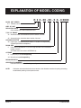
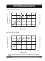
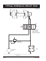
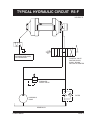
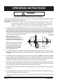
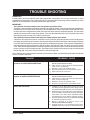
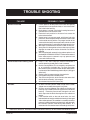
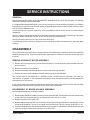
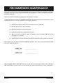
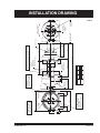
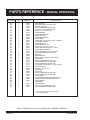
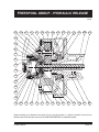
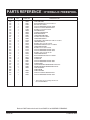
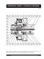
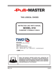
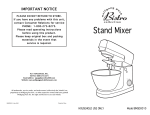
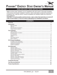
THE LOGICAL CHOICE
INSTRUCTION AND PARTS MANUAL
MODEL R5
PLANETARY HYDRAULIC WINCH
TWG Canada
LANTEC and Pullmaster Brands
19350 – 22nd Ave • Surrey, BC V3S 3S6
Voice: + 1 604-547-2100 • Fax: + 1 604-547-2147 • www.team-twg.com
READ THIS MANUAL BEFORE INSTALLING, OPERATING OR SERVICING
THIS PRODUCT. THIS MANUAL CONTAINS IMPORTANT INFORMATION.
MAKE THIS MANUAL AVAILABLE TO ALL PERSONS RESPONSIBLE
FOR THE OPERATION, INSTALLATION, SERVICING AND MAINTENANCE
OF THIS PRODUCT.
PMC 172
120612
Effective 2011/10/01
SUPERSEDES ALL PRIOR WARRANTIES
LIMITED WARR ANTY
50130-0
Seller warrants that each article (whether Gear Drive Products, Brake Products and/or Winch Products, all of which are covered
hereunder) sold under this order shall at the time of shipment (i) conform to applicable specifications, and (ii) be free from defects in
material and workmanship during normal and ordinary use and service (the "Warranty").
Buyer's exclusive remedy and Seller's sole obligation under this Warranty shall be, at Seller's option, to repair or replace any article or
part thereof which has proven to be defective, or to refund the purchase price of such article or part thereof. Buyer acknowledges that
Buyer is knowledgeable concerning the articles covered by this Warranty and sold in connection therewith which are being purchased,
that Buyer has reviewed this Warranty and that the remedies provided hereunder are adequate and acceptable to Buyer.
This Warranty shall expire one (1) year from the date the article is first shipped by Seller. Notice of claimed breach of this Warranty
must be given by Buyer to Seller within the applicable period. Such notice shall include an explanation of the claimed warranty defect
and proof of date of purchase of the article or part thereof for which warranty coverage is sought. No allowances shall be made by
Seller for any transportation, labor charges, parts, "in and out" costs, adjustments or repairs, or any other work, unless such items are
authorized in writing and in advance by Seller. Nor shall Seller have any obligation to repair or replace items which by their nature are
expendable.
If an article is claimed to be defective in material or workmanship, or not to conform to the applicable specifications, Seller will either
examine the article at Buyer's site or issue shipping instructions for return to Seller. This Warranty shall not extend to any articles or
parts thereof which have been installed, used, or serviced otherwise than in conformity with Seller's applicable specifications,
manuals, bulletins, or instructions, or which shall have been subjected to improper installation, operation, or usage, misapplication,
neglect, incorrect installation, overloading, or employment for other than normal and ordinary use and service. This Warranty shall not
apply to any article which has been repaired, altered or disassembled, or assembled by personnel other than those of Seller. This
Warranty shall not apply to any article upon which repairs or alterations have been made (unless authorized in writing and in advance
by Seller). This Warranty shall not apply to any articles or parts thereof furnished by Seller to Buyer's specifications and/or furnished
by Buyer or acquired from others at Buyer's request.
SELLER MAKES NO EXPRESS WARRANTIES AND NO IMPLIED WARRANTIES OF ANY KIND, OTHER THAN THE WARRANTY
EXPRESSLY SET FORTH ABOVE. SUCH WARRANTY IS EXCLUSIVE AND IS MADE AND ACCEPTED IN LIEU OF ANY AND ALL
OTHER WARRANTIES, EXPRESS OR IMPLIED, INCLUDING WITHOUT LIMITATION THE IMPLIED WARRANTIES OF
MERCHANTABILITY AND FITNESS FOR A PARTICULAR PURPOSE.
Buyer expressly agrees that Seller is not responsible to perform any work or investigation related in any way to torsional vibration
issues and is not responsible for the detection or remedy of Natural Frequency Vibration of the mechanical system in which the unit is
installed. Buyer acknowledges, understands and agrees that this Warranty does not cover failures of the unit which result in any
manner from the operation of the machine or unit at vibration frequencies at or near the natural frequency vibration of the machine in
such a way that damage may result. Buyer expressly agrees that Seller is not responsible for failure damage or accelerated wear
caused by machine or ambient vibration. Further, Buyer acknowledges and agrees that Buyer is always solely responsible for
determination and final approval of the “application factor” which may be used in Seller’s calculations and this application factor is 1.0
unless otherwise stated in Seller’s quotation specifications.
The remedies for this Warranty shall be only those expressly set forth above, to the exclusion of any and all other remedies of
whatsoever kind. The limited remedies set forth above shall be deemed exclusive, even though they may fail their essential purpose.
No agreement varying or extending the foregoing Warranty, remedies, exclusions, or limitations shall be effective unless in writing
signed by an executive officer of Seller and Buyer. This Warranty is non-transferable. If a party who had purchased articles from
Buyer, or from persons in privity with Buyer, brings any action or proceeding against Seller for remedies other than those set forth in
this Warranty, Buyer agrees to defend Seller against the claims asserted in such action or proceeding at Buyer’s expense, including
the payment of attorneys’ fees and costs, and indemnify Seller and hold Seller harmless of, from and against all such claims, actions,
proceedings or judgments therein. Buyer also agrees to defend and indemnify Seller of, from and against any loss, cost, damage,
claim, debt or expenses, including attorneys’ fees, resulting from any claims by Buyer or third parties to property or injury to persons
resulting from faulty installation, repair or modification of the article and misuse or negligent operation or use of the article, whether or
not such damage to property or injury to persons may be caused by defective material, workmanship, or construction.
ADVISORY: Winches and hoists are not approved for lifting or handling personnel or persons unless specifically approved in writing
from Seller for the specific intended application.
Under no circumstances shall Seller be liable (i) for any damage or loss to any property other than the warranted article or part
thereof, or (ii) for any special, indirect, incidental, or consequential damage or loss, even though such expenses, damages, or losses
may be foreseeable.
The foregoing limitations on Seller's liability in the event of breach of warranty shall also be the absolute limit of Seller's liability in the
event of Seller's negligence in manufacture, installation, or otherwise, with regard to the articles covered by this Warranty, and at the
expiration of the Warranty period as above stated, all such liabilities shall terminate. Buyer’s purchase of any article(s) covered by this
Warranty shall constitute acceptance of the terms and conditions hereof and shall be binding upon Buyer and Buyer’s representatives,
heirs and assigns. The laws of the Province of British Columbia shall govern Buyer’s rights and responsibilities in regard to this
Warranty and the transaction(s) subject thereto, and the Province of British Columbia shall be the exclusive forum and jurisdiction for
any action or proceedings brought by Buyer in connection herewith or any dispute hereunder. If any of the terms and conditions
contained within this Warranty are void, the remaining provisions thereof are and shall remain valid and enforceable.
SAFETY RECOMMENDATIONS
Definition: Caution indicates a potentially
hazardous situation which, if not avoided may
result in minor or moderate injury.
DANGER
FAILURE TO COMPLY WITH THE FOLLOWING SAFETY
RECOMMENDATIONS AND LOCAL RULES AND
REGULATIONS WILL RESULT IN PROPERTY
DAMAGE, SEVERE INJURY OR DEATH.
Definition: Warning indicates a potentially
hazardous situation which, if not avoided could
result in death or serious injury.
Definition: Danger indicates a potentially
hazardous situation which, if not avoided will
result in death or serious injury.
The planetary hydraulic winches are made for hoisting and lowering loads and to be operated by trained and professional
personnel. They are not designed for operations involving lifting or moving personnel. The winches are powered by hydraulic
power. The ropes / cables for hoisting operations are not supplied by PULLMASTER. The winches are always assembled
in an application, they do not function as an independent machine and it is not allowed to use them as such.
The winches are to be used within the specifications as listed in the manual under “SPECIFICATIONS”. Other use as foreseen
in the functional description of the hydraulic winch is not allowed without written permission from PULLMASTER.
1.
Do not install, operate or service winch before
reading and understanding manufacturer's
instructions.
2.
The winch described herein is not designed for
operations involving lifting or moving personnel.
3.
Do not lift or carry loads over people.
18.
Use only recommended hydraulic oil and gear
lubricant.
19.
Keep hydraulic system clean and free from
contamination at all times.
20.
Maintain winch and equipment in good operating
condition. Perform scheduled maintenance regularly.
4.
Do not exceed recommended operating pressure 21.
Keep hands clear when winding wire rope onto
(psi) and operating volume (gpm).
the winch drum.
5.
Do not jerk the winch. Always smoothly
accelerate and decelerate load.
22.
Do not use the wire rope as a ground for welding.
6.
Do not operate a damaged, noisy or
malfunctioning winch.
23.
Rig the winch carefully. Ensure that the wire
rope is properly anchored to the correct cable anchor
slot at the cable drum.
7.
Do not leave a load suspended for any
extended period of time.
24.
Do not lift a load with a twisted, kinked or
damaged wire rope.
8.
25.
Consult wire rope manufacturer for size, type
and maintenance of wire rope.elen
Never leave a suspended load unattended.
9.
Winch should be maintained and operated by
qualified personnel.
10.
Inspect winch, rigging, mounting bolts and
hoses before each shift.
11.
Warm-up equipment before operating winch,
particularly at low ambient temperatures.
12.
Verify winch function by raising and lowering a
full test load to a safe height before each shift.
13.
Do not weld any part of the winch.
14.
Verify gear lubrication and brake circulation
supply and return before operating winch.
15.
Be sure of equipment stability before operating
winch.
16.
Wear proper clothing to avoid entanglement in
rotating machinery.
17.
26.
Maintain five wraps of wire rope on the cable
drum at all times.
27.
In case of a power failure or breakdown leading
to an unexpected stop of the hydraulic power circuit,
stand clear of the area and the load being hoisted,
take the necessary precautions to prevent access to
area where the load is halted.
28.
The noise level of the winch is 83 dBA measured
on a distance of 1.00 meter, 1.60 meters high. The
measuring equipment used was: Realistic #42-3019.
29.
Clean up any oil spillage immediately.
30.
Wear proper clothing and personal protection
equipment such as, footwear, safety goggles and a
hard hat. Read manual first.
Always stand clear of the load.
172 REV.051117
PAGE 1
DESCRIPTION OF THE MODEL R5
GENERAL DESCRIPTION:
The PULLMASTER Model R5 is a planetary, hydraulic winch primarily intended for mobile or recovery adaptations.
The winch has equal speed in both directions and a freespool feature which can be operated manually or
hydraulically, depending on the option. The main components of this unit are:
✛
✛
✛
✛
✛
✛
✛
high torque, low speed hydraulic motor
multi-disc brake with over-running clutch
planetary reduction
brake housing
cable drum
final drive housing
freespool mechanism
FUNCTION IN FORWARD ROTATION (PULLING):
In forward rotation, or when the winch is pressurized for pulling, the output torque and rpm of the hydraulic motor
are transmitted through the brake shaft and freespool coupling to the final sungear. The planet gears are driven by
the final sungear and cause the planet hub to drive the cable drum at a reduction of 9.25:1. When a load is pulled,
an over-running clutch which connects the motor drive shaft to the automatic brake assembly, permits free rotation
of the sungear, without effecting the brake. When the winch rotation is stopped, the load on the cable drum causes
the over-running clutch to lock and the load is held safely by the disc brake.
FUNCTION IN REVERSE ROTATION (PAYING OUT):
In reverse rotation, or paying out of a load, hydraulic pressure from the reverse side of the hydraulic motor is
channelled to the brake piston, causing the brake piston to release the multi-disc brake. The pressure required to
release the brake is 400 - 600 psi (28 - 42 bar). The over-running clutch, connecting the motor drive shaft to the brake
assembly, locks, causing the brake discs to rotate between stationary divider plates. If the load on the cable drum
increases the pay out speed, the resulting pressure drop in the brake piston increases friction between the friction
plates and slows the drum. In this way, a completely smooth pay out speed can be achieved in a stepless operation
by modulation of the winch control valve. When the control valve is returned to neutral position, rotation stops and
the disc brake applies automatically.
During pay out operations of the winch, the friction created by the brake discs results in heat. This heat is dissipated
by the circulation of hydraulic fluid from the brake housing, supplied internally through the hydraulic motor. This
circulation flow is internally vented to the return line through a check valve arrangement inside the specially modified
motor. The circulation flow is supplied only when the wire rope is payed out. A separate vent line connecting the
PULLMASTER Model R5 with the hydraulic reservoir is not required (see TYPICAL HYDRAULIC CIRCUIT).
IMPORTANT:
SAFETY VALVE
The PULLMASTER Model R5 winch does not require a drain line up to 100 psi permissible back
pressure in the brake housing. To indicate excessive pressure and potential damage to the
hydraulic motor or to the oil seal in the brake housing, a safety valve is installed on the motor
adaptor.
BREATHER RELIEF VALVE
Excessive pressure in the brake housing will damage the oil seal separating the brake housing from
the drum interior. Damage to this seal will cause the drum to fill up with hydraulic fluid. To prevent
damage to the drum seal and end cover of the final drive if the cable drum fills up with hydraulic
fluid, a breather relief (PARTS REFERENCE item 130) is installed on the end cover. The breather
relief does not prevent oil seal failure but serves as an indicator or warning that the seals between
brake housing and the cable drum interior have failed and must be replaced immediately.
PAGE 2
172 REV.950101
DESCRIPTION OF THE MODEL R5
CONTINUED
FUNCTION OF THE FREESPOOL MECHANISM:
MODEL R5-12-70-1M
This model has a manually actuated freespool function. The freespool feature is enabled by turning the freespool
handle 180 degrees in a counterclockwise direction. This will disengage the final sungear from the freespool coupling
and provide for a free turning drum. To re-engage the freespool coupling, turn the handle 180 degrees in a clockwise
direction.
IMPORTANT: The freespool function cannot be engaged or disengaged under load or while the
cable drum is rotating.
MODEL R5-12-70-1F
This model has a hydraulically actuated freespool feature. The final sungear is pulled out of engagement with the
freespool coupling, by the freespool piston, which is spring applied and pressure released. To disengage the
freespool coupling, hydraulic pressure of 400 psi (28 bar) must be supplied to the freespool release port (see
INSTALLATION DRAWING). When the hydraulic pressure is removed, the freespool coupling will re-engage.
IMPORTANT: The freespool coupling cannot be engaged or disengaged under load or while
the cable drum is rotating.
172 REV.950101
PAGE 3
EXPLANATION OF MODEL CODING
R 5 X - XX - XX - X X - X XXXX
BASIC UNIT SERIES
R = Recovery winch
SIZE OF UNIT
REDUCTION RATIO
Only used for non-standard reduction ratios
TYPE OF BRAKE
-12
Automatic brake, counterclockwise drum rotation, intravent
-15
Automatic brake, clockwise drum rotation, intravent
HYDRAULIC MOTOR
-70 High torque, low speed hydraulic motor, 12.9 cubic inch displacement
(Other displacements are optional)
DRUM SIZE
-1
5.0 inch drum diameter X 11 3/8 inch flange diameter X 9 inch between
flanges - STANDARD
(For other drum sizes refer to APPENDIX A)
OPTIONS
- F Hydraulically actuated freespooling
- M Manually actuated freespooling
DESIGN REVISION
SPECIFICATION NUMBER
Describes features not identified by preceding codes
NOTE:
PAGE 4
Clockwise and counterclockwise drum rotation is the direction of rotation for pulling or hoisting,
established by looking at the hydraulic motor.
172 REV.010215
OPTIONS
CLOCKWISE ROTATION:
The drum rotation of the standard PULLMASTER Model R5 planetary winch is counterclockwise for pulling when
looking at the hydraulic motor of the winch. Drum rotation for clockwise hoisting direction is available as an option.
CABLE DRUM SIZES:
Refer to APPENDIX A for optional cable drum sizes and specifications.
OPTIONAL HYDRAULIC GEAR MOTOR:
The performance of the standard PULLMASTER Model R5 planetary winch is based on a NICHOLS Series 110 IGR
hydraulic motor with a displacement of 12.9 cubic inches. The performance of the winch can be changed by using
motors with different displacements.
(Contact the factory for performance information if using motors with different displacements.)
The PULLMASTER WINCH CORPORATION will consider other options for quantity requirements.
172 REV.950101
PAGE 5
SPECIFICATIONS
Performance specifications are based on standard hydraulic motor, gear ratio and cable drum with 1/2 inch diameter
wire rope. For other cable drums refer to APPENDIX A. Performance specifications for winches supplied with
optional motors are provided in attached supplement.
CABLE DRUM DIMENSIONS (STANDARD DRUM):
Barrel diameter
Flange diameter
Barrel length
5.00 in
11.38 in
9.00 in
127 mm
289 mm
229 mm
1394 ft
732 ft
481 ft
337 ft
268 ft
209 ft
160 ft
425 m
223 m
147 m
103 m
82 m
64 m
49 m
2350 psi
162 bar
MAXIMUM OPERATING VOLUME:
15 (US) gpm
57 l/min
MINIMUM OPERATING VOLUME:
5 (US) gpm
19 l/min
DRUM TORQUE AT MAXIMUM PRESSURE:
30,305 lb-in
3,424 Nm
CABLE STORAGE CAPACITY:
(Size of wire rope)
3/16 in
1/4 in
5/16 in
3/8 in
7/16 in
1/2 in
9/16 in
MAXIMUM OPERATING PRESSURE:
DRUM RPM AT MAXIMUM VOLUME:
26 rpm
LINE PULL AT MAXIMUM PRESSURE:
Bare drum
Full drum
11,020 lb
5,573 lb
49.0 kN
24.8 kN
37 fpm
74 fpm
11 m/min
23 m/min
100 psi
6.9 bar
LINE SPEED AT MAXIMUM VOLUME:
Bare drum
Full drum
PERMISSIBLE SYSTEM BACK PRESSURE
AT MOTOR RETURN PORT:
LUBRICATING OIL:
PAGE 6
Refer to RECOMMENDATIONS for viscosity and instructions.
Refer to APPENDIX A for oil volume required.
172 REV.030429
PERFORMANCE GRAPHS
PG-R5
LINE PULL VS. OIL PRESSURE:
176
UM
2000
LL
UM
DR
AN
DR
141
UM
ME
FU
OIL PRESSURE kg/cm
OIL PRESSURE PSI
2500
R
ED
R
BA
1500
105
1000
70
500
35
2
0
0
0
2204
4408
6612
8816
11020
lb.
0
1000
2000
3000
4000
5000
kg.
LINE PULL
LINE SPEED VS. OIL VOLUME:
57
DR
UM
UM
N
EA
RE
12
BA
M
OIL VOLUME LITERS/MIN
OIL VOLUME GPM (US)
15
M
RU
DR
D
LL
45
FU
9
34
6
23
3
11
0
0
0
16
33
49
66
82
fpm
0
5
10
15
20
25
m/min
LINE SPEED
Performance graphs are based on standard hydraulic motor and cable drum with 1/2 inch diameter
wire rope.
172REV.950101
PAGE 7
TYPICAL HYDRAULIC CIRCUIT R5-M
HC-R5-M-C
CONTROL VALVE
(MOTOR SPOOL)
4-WAY SPRING
RETURN TO CENTER
PRESSURE
RELIEF VALVE
FILTER
HYDRAULIC
PUMP
RESERVOIR
PAGE 8
172 REV.030429
TYPICAL HYDRAULIC CIRCUIT R5-F
HC-R5-F-C
400 PSI (28 BAR)
PRESSURE REQUIRED
FOR FREESPOOL
CONTROL VALVE
(MOTOR SPOOL)
4-WAY SPRING
RETURN TO CENTER
PRESSURE
RELIEF VALVE
FILTER
HYDRAULIC
PUMP
RESERVOIR
172 REV.030429
PAGE 9
RECOMMENDATIONS
HYDRAULIC FLUID:
HYDRAULIC PRESSURE RELIEF:
The hydraulic fluid selected for use with PULLMASTER
planetary winches should be a high grade, petroleum
based fluid, with rust, oxidation and wear resistance.
Fluid cleanliness and operating viscosity are critical to
winch reliability, efficiency and service life.
The hydraulic circuit for the PULLMASTER planetary
winch requires a pressure relief set at the operating
pressure (see SPECIFICATIONS). Usually, a pressure
relief is part of the hydraulic control valve. Where this is
not the case, a separate pressure relief valve must be
installed and set at the recommended maximum pressure.
For optimum performance, the recommended viscosity
range at operating temperature is 81 - 167 SUS (16 - 36
CS). For extreme operating conditions of short duration,
the maximum viscosity range of 58 - 4635 SUS (10 1000 CS) should not be exceeded.
For optimum performance, the winch recommended
hydraulic fluid temperature operating range is 80 - 150F
(27 - 66 C). For extreme operating conditions of short
duration, the maximum temperature range of -5 - 180F
(-21 - 82 C) should not be exceeded.
LUBRICATION:
The winch gear train requires oil bath lubrication. The
winch is shipped from the factory without lubricating oil.
HYDRAULIC RESERVOIR:
It is recommended that the hydraulic reservoir has
sufficient capacity to provide good heat dissipation in
order to prevent over-heating of the hydraulic fluid. The
hydraulic reservoir should be made from clean and
scale-free material to prevent contamination of the
hydraulic fluid. In order to prevent air from being mixed
with the hydraulic fluid, the reservoir should have an
over-flow baffle separating the return lines from the
suction line and all return lines should enter the reservoir
below the fluid level. The reservoir should be mounted
close to and above the hydraulic pump in a location
which provides for free air circulation around the reservoir.
HYDRAULIC HOSES:
IMPORTANT:
ADD LUBRICATING OIL BEFORE
RUNNING WINCH.
Refer to INSTALLATION DRAWING for location of
lubricating oil fill port. Refer to APPENDIX A for quantity
of oil required. For normal operating temperatures use
SAE 90 lubricating oil. Consult lubricating oil supplier or
factory for temperature beyond normal operating range.
HYDRAULIC PUMP:
For maximum performance of the PULLMASTER
planetary winch, the hydraulic pump must supply the
maximum flow of hydraulic fluid at the hydraulic pressure
stated in SPECIFICATIONS.
HYDRAULIC CONTROL VALVE:
The standard control valve used for operation of the
PULLMASTER planetary winch must have a four-way,
spring return to neutral feature, which provides for open
flow from the pressure ports of the winch to the reservoir
in neutral position of the control (motor spool). It is
important to point out that good speed control, especially
when lowering a load, depends on the "metering"
characteristics of the control valve. The better the oil
flow is "metered" the better will be the speed control.
PAGE 10
The following hydraulic hoses are recommended for
maximum efficiency of the PULLMASTER Model R5
planetary winch:
Pressure lines:
Hydraulic freespool line:
Equivalent to SAE 100R12-12
Equivalent to SAE 100R3-3
It is recommended that a larger size of hydraulic hose is
installed where the pressure lines or the circulation lines
are excessively long.
HYDRAULIC FILTER:
Hydraulic filter recommendations for the hydraulic circuit
of the PULLMASTER planetary winch, based on a return
line filter, are given as follows:
Average atmosphere:
Dusty atmosphere:
10 microns
5 microns
In order to prevent accidental stoppage of the return line
flow, the oil filter should have a by-pass feature.
USE OF AN E STOP:
The use of an E stop (emergency) is mandatory in the
controls circuit, the E stop is to be placed in the
operators control panel. The E stop has to be designed
and placed in line with EN 60204 and EN 418.
172 REV.030429
INSTALLATION INSTRUCTIONS
DANGER
FAILURE TO FOLLOW INSTALLATION INSTRUCTIONS COULD
RESULT IN PROPERTY DAMAGE, SEVERE INJURY OR DEATH.
The initial installation or mounting of a PULLMASTER planetary winch is critically important for proper operation
and performance. If the winch is mounted to an uneven surface, the centre line of the unit can be distorted to a point
where the winch will not operate in either direction. It is therefore very important that the following instructions are
observed when a PULLMASTER planetary winch is installed:
1) Make certain that the mounting platform is sufficiently strong in order to avoid deflection when a load is lifted.
2) Set the winch on the mounting platform and check for surface contact on all mounting pads of the winch.
3) If there is a space between the mounting surface and one of the mounting pads, the mounting surface is not
even and the space below the mounting pad must be shimmed. If this condition exists, proceed as follows:
a) Install mounting bolts snug tight on the three mounting pads which are in contact with the mounting surface.
(For mounting bolt size and grade see INSTALLATION DRAWING.)
b) Measure the space underneath the fourth mounting pad with a feeler gauge and use shim stock of equivalent
thickness in the space between the mounting pad and the mounting surface.
c) Only after this procedure should the fourth mounting bolt be installed. Tighten all four bolts per BOLT
TORQUE CHART.
4) Fill the winch with lubricating oil. (See APPENDIX A for oil volume required.)
5) Use recommended circuit components and hydraulic hoses.
6) The circulation return line of the winch should be plumbed in such a manner that the brake housing remains
full of oil at all times. Connect the return line directly to reservoir. Do not connect to a common return line.
7) Verify that breather relief, item 130, is in place on end cover above oil level. End cover may need to be rotated
if winch is not installed upright.
IMPORTANT:
172 REV.030429
Do not replace breather relief or safety valve with a pipe plug. The breather relief does
not prevent oil seal failure but serves as an indicator or warning that the oil seals
between brake housing and the cable drum interior have failed and must be replaced
immediately. The safety valve acts as a warning that excessive pressure is present
in the brake housing and must be rectified immediately.
PAGE 11
OPERATING INSTRUCTIONS
DANGER
FAILURE TO FOLLOW OPERATING INSTRUCTIONS COULD
RESULT IN PROPERTY DAMAGE, SEVERE INJURY OR DEATH.
After the PULLMASTER planetary winch has been installed in accordance with the INSTALLATION INSTRUCTIONS,
the wire rope can be fastened to the cable drum.
IMPORTANT: The ropes, chains, slings, etc. are not part of the winch and are not covered by this manual. Refer
to manufacturer’s handling, inspection and maintenance recommendations to avoid potential
accidents. For selection of ropes, etc. please check following product standards: DIN 15020,
prEN818-1/9, prEN 1492-1/2, prEN 1677-1/3 and other relevant product standards.
1) The cable drum of the PULLMASTER planetary winch has two cable anchor slots, one for clockwise and one
for counterclockwise pulling. Standard rotation for pulling is counterclockwise when looking at the hydraulic
motor of the unit. It is critical to select the cable anchor slot which will permit winding of the wire rope on the
drum in the correct direction of rotation. If the wire rope is wound on the cable drum in the wrong direction of
rotation, the winch will have no braking capacity. Each winch is shipped from the factory with a label on the
drum indicating the correct cable anchor slot.
SI1013-R5
WIRE ROPE INSTALLATION
Counterclockwise pulling winch shown.
(Use cable anchor slot on opposite
side of drum for clockwise pulling winch.)
Feed the wire rope through the cable
anchor slot. Loop rope back into slot
as shown. Insert cable anchor into
slot, small end first and long side
nearest the drum flange. Pull rope
tight to wedge rope in slot.
CABLE ANCHOR SLOT
CABLE ANCHOR
2) On wire rope installation, care must be taken that the wire rope is wrapped completely around the cable anchor
and properly pulled into the cable anchor slot in the cable drum. The cable drum requires 5 wraps of wire rope
for safety.
3) The winch operation is controlled by a single control valve lever which has a forward, a reverse and a neutral
position. Speed control in either direction is obtained by modulation of the control valve lever. Maximum line
speed in either direction is obtained when the control valve lever is moved as far as it can go. The disc brake
of the winch will come on automatically when the winch control lever is returned to neutral.
4) Always warm up equipment prior to operating winch, particularly in low ambient temperature. Circulate hydraulic
oil through the winch control valve for several minutes to warm the hydraulic system. To prime the winch with
warm oil, operate the winch at slow speed, forward and reverse, several times.
5) Prevent corrosion damage to winch interior. If not used regularly, run winch up and down at least once every
two weeks.
6) To ensure proper winch installation and function, raise and lower a full test load to a safe height before using
winch for regular operation at the start of each shift.
If, after a new installation, the winch does not function properly, refer to the TROUBLESHOOTING section of
this manual.
PAGE 12
172 REV.051117
TROUBLE SHOOTING
GENERAL:
In most cases, when the hydraulic winch does not perform satisfactorily, the cause of malfunction is found
somewhere in the hydraulic circuit. Before the winch is removed from its mounting and disassembled, all of the
hydraulic circuit components should be checked for proper function.
IMPORTANT:
The hydraulic oil volume relates to the line speed or rpm of the winch.
Therefore, if the winch does not produce the maximum rated line speed, a loss of hydraulic flow somewhere in
the hydraulic circuit system can be analysed. If this condition exists, install a flow meter into the hydraulic circuit
to check the volume supplied to the motor ports when the winch control is completely opened. The flow meter
should indicate the maximum operating volume. If the test described indicates a loss of hydraulic flow, check
the hydraulic pump, the relief valve and the control valve.
The hydraulic pressure relates to the line pull or lifting capacity of the winch.
If the winch will not pull the maximum rated load, install a pressure gauge into the pressure line leading to the
pulling port on the hydraulic winch motor. Stall the winch to prevent rotation of the drum and then open the control
valve and check the hydraulic pressure reading of the installed pressure gauge. If the pressure reads below the
specified maximum operating pressure, look for trouble in the hydraulic pump, the relief valve and the control
valve. When checking oil pressure of oil volume anywhere in the hydraulic system, make certain that the hydraulic
pump is running at maximum operating rpm. Installations using a belt drive for hydraulic pump must be checked
for belt slippage. Verify that hydraulic reservoir is filled to the top level.
Only if the hydraulic system has been checked and found to be in order, use the following indications for probable
causes of failure in the winch:
PROBABLE CAUSE
FAILURE
Winch will not produce line pull at maximum
pressure as listed in SPECIFICATIONS.
a)
b)
c)
d)
e)
Winch will not produce line speed at maximum
volume as listed in SPECIFICATIONS.
a)
b)
c)
d)
Winch will not reverse.
a)
b)
c)
d)
e)
172 REV.950101
Winch is mounted to an uneven surface (see
INSTALLATION INSTRUCTIONS).
Cable sheaves or block purchase operated with the
winch are not turning freely.
Damage or wear in the hydraulic motor.
Excessive back pressure in the hydraulic system.
Relief valve may be set too low.
Winch is mounted to an uneven surface (see
INSTALLATION INSTRUCTIONS).
Cable sheaves or block purchase operated with the
winch are not turning freely.
Damage or wear in the hydraulic motor
Excessive back pressure in the hydraulic circuit.
Leakage out of the brake piston prevents the brake
from being released against the brake springs. This is
caused by damaged O-ring seals on the brake piston.
The O-ring seals, on the brake release channel between
the motor adaptor and the brake housing is damaged.
If this failure occurs there will be substantial leakage
from between the motor adaptor and brake housing.
Insufficient hydraulic pressure (see SPECIFICATIONS
for minimum operating pressure).
Winch is mounted to an uneven surface (see
INSTALLATION INSTRUCTIONS).
Hydraulic pressure is not reaching the brake piston
(plugged brake release orifice in the brake housing).
PAGE 13
TROUBLE SHOOTING
FAILURE
PROBABLE CAUSE
Brake will not hold.
a) Friction plates or divider plates have been damaged by
contamination in the hydraulic fluid, or lack of circulation
flow in the brake housing.
b) Brake piston is seized in the brake housing because of
contamination in the hydraulic fluid.
c) Excessive back pressure in the return line causes the
brake to be released.
d) Control valve has incorrect spool, which traps hydraulic
pressure in the brake piston when the control valve handle
is returned to neutral position. For proper function of the
automatic brake, both pressure ports of the winch must be
open to the reservoir in neutral position of the control valve.
e) Wire rope is fastened to the incorrect cable anchor slot.
f) Sprag clutch is damaged or surfaces where sprag clutch
engages on motor drive shaft or brake hub are worn or
indented.
g) Winch supplied with external brake release option is not
plumbed per HYDRAULIC CIRCUIT. Failure to vent external
brake release port to reservoir may trap pressure and
cause winch brake to slip.
Brake vibrates when lowering a load.
a) Pump is too slow. Pump rpm must be maintained at
normal operating speed when a load is lowered.
b) Brake is running too hot. This is caused by a complete lack
of, or insufficient circulation flow. To check circulation
flow, remove safety valve from motor adaptor. When winch
is reversed, oil flow should be approximately 2.5 (US) gpm
(9 liter/min).
c) Control valve has poor metering characteristics.
d) Damaged brake plates or divider plates.
e) The over-running clutch, which connects the motor shaft
with the brake assembly, is damaged.
f) Air mixed with hydraulic oil (foamy oil).
Oil leaks.
a) Oil leaks from the hydraulic motor flange and the motor
adaptor are caused by damaged O-ring seals.
b) Oil leaks occurring between the cable drum flanges and
housings are caused by excessive pressure in the brake
housing. Excessive pressure will damage the oil seal
which separates the brake housing from the cable drum
interior.
c) If the breather relief on the end cover leaks, the seal
between the drum interior and the brake housing is damaged
and must be replaced. This condition is caused by excessive
pressure in the brake housing of the winch, operation with
the incorrect hydraulic fluid during cold weather, or a
restriction in the circulation return line leading back to tank.
Refer to the SERVICE INSTRUCTIONS if it becomes necessary to disassemble the Model R5 winch.
PAGE 14
172 REV.950101
SERVICE INSTRUCTIONS
GENERAL:
Before attempting disassembly of the PULLMASTER Model R5 planetary winch with freespool, the following
instructions should be read and understood.
It is suggested that all expendable parts, such as O-rings and oil seals are not reused on reassembly. It is therefore
important to have a winch seal kit (Part No. 25829), and providing the hydraulic motor has to be serviced, a motor
seal kit (Part No. 25688) on hand.
A clean working area is of prime importance, similar to conditions used for service work on any other hydraulic
components.
All parts, as they are removed from the winch assembly, should be inspected for wear and damage. Thoroughly
clean parts before reassembly, however, do not use solvent to clean friction plates.
During reassembly, lubricate all O-rings and oil seals with grease.
In the following service instructions, reference to parts is made by numbers and shown on the applicable group
drawings.
DISASSEMBLY
The majority of service or repair work is accomplished by disassembling the brake housing of the PULLMASTER
Model R5 planetary winch. There are no special tools, adjustments or calibrations necessary to service or repair
the winch.
REMOVE HYDRAULIC MOTOR ASSEMBLY:
1) Remove two capscrews item 815, and lockwashers item 817. Pull the hydraulic motor item 850, out of the
winch assembly.
2) Remove and discard O-ring item 811.
3) Remove connecting tube item 830. Remove and discard two O-rings item 831.
4) Remove two check valves item 832. Remove and discard two O-rings item 833.
The standard motor of the Model R5 is a NICHOLS Series 110 IGR hydraulic motor with 12.9 cubic inch
displacement. If a problem is analysed to be in the hydraulic motor, we recommend that a NICHOLS dealer be
contacted for parts and service.
If the hydraulic motor is disassembled, the original flange section of the motor must be re-used in order to provide
the required porting to operate the automatic brake and for the circulation flow.
DISASSEMBLY OF BRAKE HOUSING ASSEMBLY:
Disassemble brake housing assembly as follows:
1) Remove motor adaptor item 800, by removing six capscrews item 821, and lockwashers item 823. Allow brake
springs item 752, to expand safely by unscrewing capscrews one turn at a time.
2) Remove and discard O-ring item 707.
3) Remove eight brake springs item 752. Examine brake springs for damage and measure overall length. Overall
spring length should be 1.54 inch. If any spring measures less than 1.48 inch, replace all springs as a set.
4) Pull the brake piston item 750, out of the brake housing using two 1/2 - 13NC bolts screwed into the two puller
holes in the piston and discard O-rings item 751 and item 753.
172 REV.030429
PAGE 15
SERVICE INSTRUCTIONS CONTINUED
5) Remove pipe plug item 755, and verify that circulation hole in piston is clear and unobstructed. Re-install pipe
plug item 755.
6) Thoroughly inspect the brake piston outer diameters and brake housing inner bores for scoring caused by
hydraulic fluid contamination. Minor surface damage may be repaired by polishing with a fine emery cloth.
7) Remove coupling fastener item 738, from center of brake shaft item 730.
8) Pull the brake shaft item 730, and complete brake hub assembly from the brake housing.
9) Disassemble brake hub assembly by removing circlip item 727, from brake shaft item 730. Remove brake shaft
from brake hub assembly. Remove sprag clutch aligners item 722 and item 724, and sprag clutch item 723,
from brake hub.
DANGER
MINOR SURFACE DEFECTS WHERE THE SPRAG CLUTCH ENGAGES THE
MOTOR DRIVE SHAFT AND BRAKE HUB, WILL RESULT IN BRAKE
FAILURE AND ALLOW THE LOAD TO DROP, CAUSING PROPERTY
DAMAGE, SEVERE INJURY OR DEATH. THOROUGHLY INSPECT
THESE AREAS AND, IF NECESSARY, REPLACE BRAKE SHAFT,
SPRAG CLUTCH AND BRAKE HUB AS A SET.
10) Thoroughly inspect brake shaft item 730, and brake hub item 720, particularly the surfaces where the sprag
clutch item 723, engages. If any indentation or surface damage is detected, replace brake hub, sprag clutch
and brake shaft as a set.
11) Remove the 14 divider plates item 713, together with 13 brake plates item 715, and inspect for damage or wear.
Plates should not show heat discoloration. Paper material on friction plates should be intact and smooth. If any
damage is detected, replace friction and divider plates as a set. Check oil for contamination if plates are in poor
condition.
DANGER
DAMAGED FRICTION OR DIVIDER PLATES WILL REDUCE BRAKING
CAPACITY AND ALLOW THE LOAD TO DROP CAUSING PROPERTY
DAMAGE, SEVERE INJURY OR DEATH. DO NOT USE SOLVENT TO
CLEAN THE FRICTION PLATES. PERFORM THOROUGH
INSPECTION AND, IF NECESSARY, REPLACE FRICTION
AND DIVIDER PLATES AS A SET.
12) Remove brake spacer item 712, two thrust washers item 615, and thrust bearing item 617.
13) Remove bronze washer item 706. Remove and discard oil seal item 711, and backup washer item 710.
All parts have now been removed from the brake housing and there is no need for further disassembly unless a failure
has been analysed in the final drive or freespool mechanism of the Model R5.
DISASSEMBLY OF FINAL DRIVE ASSEMBLY:
If a failure occurs in the mechanism located inside the final drive housing, or the winch has to be disassembled
beyond the point described in the preceding chapter, proceed as follows:
1) Remove the drain plug item 121, from the freespool housing item 250, and drain the lubricating oil from the final
drive assembly and the cable drum interior. In order to drain all of the oil out of the cable drum interior, the winch
should be tipped to an angle and the filler plug item 503, removed.
PAGE 16
172 REV.030429
SERVICE INSTRUCTIONS CONTINUED
2) After draining all lubricating oil from the final drive housing item 100, remove internal retaining ring item 124.
The freespool assembly, along with the final sungear, can now be pulled out of the final drive housing and put
aside. If a problem exists in the freespool assembly, skip ahead to the section titled DISASSEMBLY OF
FREESPOOL ASSEMBLY.
3) Remove final planet hub assembly from final housing item 100.
4) Inspect three final planet gears item 320, for damage or wear. If it is necessary to remove planet gears, remove
circlip item 311, and press planet pin item 310, out of the final planet hub item 300. Inspect needle bearing item
323, and two thrust washers item 321, and replace if damaged.
All parts have now been removed from the final drive assembly. If further disassembly is required,
proceed as follows:
DISASSEMBLY OF CABLE DRUM ASSEMBLY:
To separate brake housing item 700, and final housing item 100, from cable drum item 500, proceed as follows:
1) Remove 16 capscrews item 971, and lockwashers item 973. Remove two tie bars item 970. Stand the winch
upright on its end housing.
2) Insert two heel bars between the flange of the cable drum item 500, and the brake housing item 700, and gently
pry the brake housing out of spherical roller bearing item 507.
3) Remove freespool coupling item 260, from brake housing. Remove O-ring item 293, from freespool coupling
and discard.
4) Inspect journal bearing item 286, for excessive wear and replace if necessary.
5) Remove and discard oil seal item 515.
6) Inspect spherical roller bearing item 507, and replace if damaged.
7) Turn winch over to stand upright on the drum flange. Remove circlip item 513, from splined hub of cable drum
item 500.
8) Insert two heel bars between the drum flange and the final housing and carefully pry the cable drum out of ball
bearing item 103.
9) Remove and discard oil seal item 105. If removal of ball bearing item 103, is necessary, first remove circlip
item 109.
DISASSEMBLY OF FREESPOOL ASSEMBLY:
If a problem in the freespool assembly is analysed, follow instructions 1) and 2) from the section
titled DISASSEMBLY OF FINAL DRIVE ASSEMBLY, then proceed to the appropriate sub heading
of HYDRAULIC or MANUAL FREESPOOL:
HYDRAULIC FREESPOOL (R5-X-70-1F):
1) Remove four hex capscrews item 253, and lockwashers item 255, from the end of the freespool assembly.
Since the freespool spring item 280, applies pressure against the inside of the freespool cover, it is
recommended that the hex capscrews are unscrewed one turn at a time, evenly, until the spring pressure has
been released.
2) Discard O-ring item 257, and remove freespool spring item 280.
3) Remove the freespool piston item 264, along with the final sungear item 340, from the freespool cover and
discard O-rings item 265 and item 277. Inspect the outside diameter of the piston and the internal diameter of
the housing for any scoring caused by hydraulic fluid contamination. Minor surface damage may be repaired
by polishing with a fine emery cloth.
172 REV.030429
PAGE 17
SERVICE INSTRUCTIONS CONTINUED
4) Inspect nylon planet hub stopper item 126, and replace if less than 0.14 inch thick. Remove and discard Oring item 123, from outside of freespool housing.
5) To separate the final sungear item 340, from the freespool piston, remove circlip item 269. Inspect the two
splines on the end of the final sungear for wear and cracks. Replace if necessary.
6) To separate the ball bearing item 291, from the freespool piston, remove circlip item 267.
MANUAL FREESPOOL (R5-X-70-1M):
1) Remove hex head capscrew item 297, and lockwasher item 298, to allow removal of freespool handle item 254,
from nut drive item 256.
2) Remove four hex head capscrews item 253, and lockwashers item 255, from seal carrier item 252. For correct
positioning of the seal carrier upon reassembly, make a chalk mark on the seal carrier and freespool housing item
250. Pull the seal carrier out of the freespool housing, discard O-ring item 257, and oil seal item 299.
3) Remove index pin item 272, detent spring item 276, and spring seat item 284. Check these parts for wear and
replace if necessary.
4) Turn the nut drive item 256, to disconnect from the follower item 266. Inspect the three spring pins item 278,
and replace if damaged or worn.
5) Remove circlip item 288, and pull the final sungear item 340, together with the follower and ball bearing item
291, out of the freespool housing.
6) Remove circlip item 295, from the inside of the follower and pull the ball bearing, together with the final sungear,
out of the follower.
7) To remove ball bearing item 291, from the final sungear, remove circlip item 269.
The PULLMASTER Model R5 winch has now been completely disassembled.
REASSEMBLY
Thoroughly clean and lubricate all parts. Use only new, well-greased O-rings and oil seals. Unless otherwise
specified, torque fasteners per BOLT TORQUE chart at back of manual.
REASSEMBLY OF FREESPOOL ASSEMBLY:
MANUAL FREESPOOL (R5-X-70-1M):
1) Press ball bearing item 291, onto final sungear item 340, and secure with circlip item 269.
2) Slide freespool follower item 266, over ball bearing item 291, and fasten between two circlips item 295.
3) Insert follower into bore of freespool housing item 250, and secure with circlip item 288.
4) Engage nut drive item 256, with freespool follower item 266, by twisting three spring pins item 278, into grooves
of follower.
5) Place two spring seats item 284, together with detent springs item 276, and indexes item 272, into holes in end
of nut drive item 256.
6) Press new, well-greased oil seal item 299, into seal carrier item 252.
7) Install new, well-greased O-ring item 257, onto seal carrier, and fasten onto freespool housing item 250, using
four capscrews item 253, and lockwashers item 255. Check chalk marks for proper positioning before
tightening.
PAGE 18
172 REV.030429
SERVICE INSTRUCTIONS
CONTINUED
8) Attach freespool handle item 254, to nut drive item 256, with capscrew item 297, and lockwasher item 298.
Verify handle is in PULLING position when sungear is fully extended.
9) Install new, well-greased O-ring item 123, into freespool housing item 250. Verify that planet hub stopper item
126, is in place.
HYDRAULIC FREESPOOL (R5-X-70-1F):
1) Press ball bearing item 291, onto final sungear item 340, and secure with circlip item 269.
2) Slide freespool piston item 264, over ball bearing item 291, and retain with circlip item 267.
3) Install a new, well-greased O-ring item 277, into O-ring groove inside freespool housing. Install new, wellgreased O-ring item 265, onto freespool piston item 264.
4) Insert final sungear item 340, through opening of freespool housing.
5) Install freespool spring in freespool piston item 264.
6) Install new, well-greased O-ring item 257, on freespool cover item 252.
7) Fasten freespool cover item 252, using four capscrews item 253, and lockwashers item 255. Tighten capscrews
one turn at a time to compress freespool spring.
REASSEMBLY OF CABLE DRUM ASSEMBLY:
Reassemble cable drum assembly by reversing the disassembly procedure.
1) Press ball bearing item 103, into final housing item 100, and fasten with circlip item 109.
2) Press new, well-greased oil seal item 105, into other side of final drive housing.
3) Press final housing item 100, onto hub of cable drum item 500, and fasten with circlip item 513.
4) Turn winch over so it stands on final housing end. Press spherical roller bearing item 507, into cable drum
item 500.
5) Press new, well-greased oil seal item 515, into cable drum item 500.
6) Install new, well-greased O-ring item 293, on end of final sungear item 340, and slide final sungear through
journal bearing item 286.
7) Place brake housing item 700, into cable drum item 500. Use 16 capscrews item 971, and lockwashers item
973, to secure tie bars item 970.
REASSEMBLY OF BRAKE HOUSING ASSEMBLY:
Reassemble brake housing assembly by reversing the disassembly procedure.
1)
Install new backup washer item 710, and new, well-greased oil seal, item 711, in the bore of the brake housing.
2) Install bronze washer item 706. Place thrust bearing item 617, in between two thrust washers item 615, on top
of bronze washer item 706.
3) Install sprag clutch item 723, in bore of brake hub item 720. Insert sprag clutch aligner item 722, into one side
of the brake hub. Insert the other sprag clutch aligner item 724, into the other side of the brake hub. Carefully
slide the brake shaft item 730, through the sprag clutch aligner item 724, into the brake hub assembly and fasten
into place by installing circlip item 727.
IMPORTANT:
172 REV.030429
For proper brake function, ensure that the brake hub rotation is correct. When
viewed from the motor end, the brake shaft of a counterclockwise pulling winch
must turn freely counterclockwise and lock in the clockwise direction.
PAGE 19
SERVICE INSTRUCTIONS
CONTINUED
4) Install brake hub assembly through thrust washers item 615, engage spline with freespool coupling item 260,
and fasten with coupling fastener item 738.
DANGER
INCORRECT ASSEMBLY OF THE FRICTION PLATE AND DIVIDER PLATE
STACK WILL REDUCE BRAKING CAPACITY AND ALLOW THE LOAD
TO DROP, CAUSING PROPERTY DAMAGE, SEVERE INJURY OR
DEATH. REASSEMBLE PER INSTRUCTIONS.
5) Install brake spacer item 712, into brake housing. Starting and finishing with a divider plate, alternately install
14 divider plates item 713, and 13 friction plates item 715.
6) Liberally grease O-ring item 751, and O-ring item 753, and install on the brake piston item 750.
7) Carefully insert the brake piston into the brake housing and turn the piston to line up the bore for the connecting
tube item 830, with the bore in the motor item 850.
8) Install the eight brake springs item 752.
9) Install new, well-greased O-ring item 707, on motor adaptor pilot item 800.
10) Position motor adaptor with hydraulic motor mounting holes horizontal and the connecting tube holes of the
piston aligned with motor adaptor. Tighten six capscrews item 821, and lockwashers item 823, one turn at a
time to evenly compress springs.
REPLACE HYDRAULIC MOTOR ASSEMBLY:
1) Install new O-rings item 831, on each end of the connecting tube item 830, and apply grease liberally. Insert
the long end of the connecting tube into motor adaptor item 800.
2) Install new, well-greased O-ring item 811, on flange of the hydraulic motor, and two new, wellgreased O-rings item 834, on check valves item 832.
3) Insert check valves in face of motor and fasten motor to motor adaptor using two capscrews item 815, and
lockwashers item 817.
REASSEMBLY OF FINAL DRIVE ASSEMBLY:
Reassemble final drive assembly by reversing the disassembly procedure.
1) Return winch to a horizontal position, standing on its mounting feet.
2) Reassemble final planet hub assembly. Press pre-greased needle bearing item 323, midway into
final planet gear item 320. Position thrust washers item 321, on either side of planet gear and
press planet pin item 310, into the final planet hub item 300. Retain with circlip item 311.
3) Insert final planet hub assembly into final housing, so that spline interlocks with cable drum.
4) Install freespool housing item 250, in final housing item 100, being sure to align spring pin item 259, with notch
in final housing.
5) Install retaining ring item 124, and pipe plugs item 121.
PAGE 20
172 REV.030429
SERVICE INSTRUCTIONS
IMPORTANT:
CONTINUED
Before operating the winch, add lubricating oil up to the oil level fill port on the
freespool housing. Refer to INSTALLATION INSTRUCTIONS for location of
fill port. Refer to APPENDIX A for oil volume required.
To ensure proper reassembly, run the winch in both directions without load.
DANGER
PULLING A LOAD WITH A NEWLY SERVICED WINCH WILL ENABLE AN
INSTALLATION OR SERVICE PROBLEM TO GO UNDETECTED AND WILL ALLOW
THE LOAD TO DROP CAUSING PROPERTY DAMAGE, SEVERE INJURY OR
DEATH. TO ENSURE PROPER REINSTALLATION, REFER TO
PROCEDURES AND TESTS DESCRIBED IN "INSTALLATION"
AND "OPERATING INSTRUCTIONS".
172 REV.030429
PAGE 21
RECOMMENDED MAINTENANCE
Winch gear train lubricating oil should be changed after the initial six months or 50 hours of operation,
whichever comes first. Lubricating oil should then be changed every 12 months or 500 operating hours,
whichever comes first.
Hydraulic system fluid should be changed at least once every 12 months.
For optimum performance over an extended period of time, the following preventative maintenance service
should be done every 12 months or 500 hours, whichever comes first:
1) Disconnect all hydraulic hoses and remove the winch from its mounting.
2) Disassemble the winch as per instructions.
3) Discard and replace all O-rings and oil seals.
4) Inspect all parts for wear and replace if necessary.
5) Clean all parts and inspect for wear and damage as per instructions. Replace worn or
damaged parts as required.
6) Follow INSTALLATION and OPERATING INSTRUCTIONS when returning winch to its mounting.
When ordering parts for the PULLMASTER Model R5 planetary winch, always quote the complete model
and serial number of the unit.
MODEL NO.
_________________
SERIAL NO.
_________________
PULLMASTER WINCH CORPORATION reserves the right to change specifications and the design of
PULLMASTER planetary winches at any time without prior notice and without incurring any obligations.
PAGE 22
172 REV.030429
172 REV.051117
.6
[16]
6.9
[175]
12.5
[318]
9.875
[250.8]
CANADA
13.3
[337]
PULLING
2.8
[70]
FILLER PORT
1/2-14 NPT
HYDRAULIC FREESPOOL
RELEASE PORT
1/8-27 NPT
MODEL R5-F ONLY
2.8
[70]
FREE
SPOOLING
BREATHER
RELIEF
VALVE
FOR SAFETY:
A MINIMUM OF 5 WRAPS
OF WIRE ROPE MUST BE
MAINTAINED AT ALL TIMES
2.3
[57]
5.9
[151]
-2
-1
DRUM
6.3 [159] R5-M
5.8 [148] R5-F
DRAIN PORT
1/2-14 NPT
9.3
[211]
B
11.4
289
11.4
289
A
5.0
127
7.5
191
MANUAL
FREESPOOL HANDLE
MODEL R5-M ONLY
11.6
[295]
mm
in.
mm
in.
Units
[298.46]
11.750 c/c
29.2 [742] MODEL R5-F
29.6 [753] MODEL R5-M
4 MOUNTING HOLES
.78 [20] DIA
USE
3/4 BOLTS
GRADE 5 OR BETTER
9.0
[229]
FILLER PORT
3/8-18NPT
(LOCATED EITHER
ON BARREL OR IN
CABLE ANCHOR POCKET)
10.2
[259]
8.7
[222]
11.6
[294]
STANDARD CABLE ANCHOR #23409 GOOD
FOR 3/8" TO 9/16" DIA WIRE ROPE
PRESSURIZE
FOR CLOCKWISE
ROTATION
PRESSURIZE
FOR COUNTER
CLOCKWISE
ROTATION
COUNTER CLOCKWISE
MOTOR PORTS 7/8-14
SAE O-RING BOSS
8.2
[208]
SAFETY VALVE
INSTALLATION DRAWING
I1061-C
PAGE 23
PARTS REFERENCE - MANUAL FREESPOOL
ITEM NO.
100
103
105
109
121
123
124
126
130
250
252
253
254
255
256
257
259
266
268
269
272
276
278
284
288
291
295
297
298
299
300
310
311
313
320
321
323
340
500
502
503
513
QTY.
PART NO.
1
1
1
1
2
1
1
1
1
1
1
4
1
4
1
1
1
1
1
1
2
2
3
2
1
1
2
1
1
1
1
3
3
3
3
6
3
1
1
1
2
1
20868
25087
25933
25086
25032
25104
20898
20899
20458
20965
20966
25264
20486
25037
20477
25016
25379
20476
25387
25175
20968
20488
25383
21075
25378
25172
25179
25171
25025
26009
20877
20900
25091
25091
20113
25068
25005
20893
*
20085
25085
25055
DESCRIPTION
FINAL HOUSING
BALL BEARING 070 X 125 X 24 # 6214
OIL SEAL 80 X 100 X 7
CIRCLIP ANDERTON # N1300 - 0500
PIPE PLUG 1/2 NPT SOCKET HEAD
O-RING -273 9-3/4"ID 1/8" CS
RETAINING RING
PLANET HUB STOPPER
BREATHER RELIEF
FREESPOOL HOUSING
SEAL CARRIER
CAPSCREW - HEX HEAD 3/8 - 16NC X 1.00 GR 5
FREESPOOL HANDLE
LOCKWASHER 3/8"
FREESPOOL NUT DRIVE
O-RING - 042 3-1/4"ID 1/16" CS
SLOTTED SPRING PIN 5/32" X 1" LONG
FREESPOOL FOLLOWER
SLOTTED SPRING PIN 1/8" X 3/8" LONG
CIRCLIP ANDERTON # N1400 - 0078
INDEX PIN
DETENT SPRING
SLOTTED SPRING PIN 5/32" X 5/8" LONG
SPRING SEAT
CIRCLIP ANDERTON # N1300 - 0231
BALL BEARING 020 X 042 X 12 # 6004
CIRCLIP ANDERTON # N1300 - 0165
CAPSCREW - HEX HEAD 5/16 - 18NC X .88 GR 5
LOCKWASHER 5/16"
OIL SEAL 1.75 X 2.25 X .31
PLANET HUB
PLANET PIN
CIRCLIP ANDERTON # N1400 - 0087
CIRCLIP ANDERTON # N1400 - 0087
PLANET GEAR
THRUST WASHER TORRINGTON # TRA 1423
NEEDLE BEARING TORRINGTON # B1416
FINAL SUNGEAR
CABLE DRUM
CABLE ANCHOR
PIPE PLUG 3/8 NPT SOCKET HEAD
CIRCLIP ANDERTON # N1400 - 0262
* These parts vary according to drum code.
Refer to APPENDIX A.
Refer to PAGE 28 for winch seal kit and PAGE 30 for ASSEMBLY DRAWING.
PAGE 24
172 REV.010215
FREESPOOL GROUP - HYDRAULIC RELEASE
G1137
126
130
311
321
259
100
323
320
310
313
109
513
105
500
340
266
278
269
121
124
123
250
295
268
291
300
103
502
503
288
284
253
276
272
254
298
297
256
299
252
257
255
Groups drawings may reference more parts than are actually present in a specific assembly. Parts that are
referenced on the drawing but are not on the PARTS REFERENCE list should be ignored.
172 REV.950101
PAGE 25
PARTS REFERENCE - HYDRAULIC FREESPOOL
ITEM NO.
QTY.
PART NO.
100
103
105
109
121
123
124
126
130
250
251
252
253
255
257
259
264
265
267
269
277
280
291
300
310
311
313
320
321
323
340
500
502
503
513
1
1
1
1
2
1
1
1
1
1
1
1
4
4
1
1
1
1
1
1
1
1
1
1
3
3
3
3
6
3
1
1
1
2
1
20868
25087
25933
25086
25032
25104
20898
20899
20458
20907
25374
20903
25118
25037
25016
25379
20894
25628
25179
25175
25477
20159
25172
20877
20900
25091
25091
20113
25068
25005
20893
*
20085
25085
25055
DESCRIPTION
FINAL HOUSING
BALL BEARING 070 X 125 X 24 # 6214
OIL SEAL 80 X 100 X 7
CIRCLIP ANDERTON # N1300 - 0500
PIPE PLUG 1/2 NPT SOCKET HEAD
O-RING -273 9-3/4"ID 1/8" CS
RETAINING RING
PLANET HUB STOPPER
BREATHER RELIEF
FREESPOOL HOUSING
PLASTIC CAPLUG 1/8 NPT
FREESPOOL COVER
CAPSCREW - HEX HEAD 3/8 - 16NC X 1.25 GR 5
LOCKWASHER 3/8"
O-RING - 042 3-1/4"ID 1/16" CS
SLOTTED SPRING PIN 5/32" X 1" LONG
FREESPOOL PISTON
O-RING -235 3-1/8"ID 1/8" CS
CIRCLIP ANDERTON # N1300 - 0165
CIRCLIP ANDERTON # N1400 - 0078
O-RING - 236 3-1/4"ID 1/8" CS
FREESPOOL SPRING
BALL BEARING 020 X 042 X 12 # 6004
PLANET HUB
PLANET PIN
CIRCLIP ANDERTON # N1400 - 0087
CIRCLIP ANDERTON # N1400 - 0087
PLANET GEAR
THRUST WASHER TORRINGTON # TRA 1423
NEEDLE BEARING TORRINGTON # B1416
FINAL SUNGEAR
CABLE DRUM
CABLE ANCHOR
PIPE PLUG 3/8 NPT SOCKET HEAD
CIRCLIP ANDERTON # N1400 - 0262
* These parts vary according to drum code.
Refer to APPENDIX A.
Refer to PAGE 28 for winch seal kit and PAGE 31 for ASSEMBLY DRAWING.
PAGE 26
172 REV.010215
FREESPOOL GROUP - HYDRAULIC RELEASE
G1136
130
311
259
123
323
321
310
313
109
103
105
500
340
251
250
121
124
126
264
267
100
300
513
502
503
320
277
253
252
280
257
255
269
265
291
Groups drawings may reference more parts than are actually present in a specific assembly. Parts that are
referenced on the drawing but are not on the PARTS REFERENCE list should be ignored.
172 REV.950101
PAGE 27
PARTS REFERENCE - BRAKE GROUP
ITEM NO.
QTY.
260
286
293
507
515
615
617
700
706
707
710
711
712
713
715
720
722
723
724
727
730
738
750
751
752
753
755
800
811
815
817
821
823
830
831
832
834
840
850
955
970
971
973
1
1
1
1
1
2
1
1
1
1
1
1
1
14
13
1
1
1
1
1
1
1
1
1
8
1
1
1
1
2
2
6
6
1
2
2
2
1
1
2
2
16
16
DESCRIPTION
PART NO.
21015
20901
25584
25664
25665
26229
25667
20869
21048
25061
20896
25666
20874
25624
25623
20890
20421
25303
20421
25335
20891
21021
21153
25629
20859
25630
25370
*
26624
25013
25014
25013
25014
20902
25018
21524
25738
20870
*
25687
20892
25265
25328
FREESPOOL COUPLING
JOURNAL BEARING
O-RING - 016 5/8 "ID 1/16" CS
SPHERICAL ROLLER BEARING
OIL SEAL 3.375 X 4.000 X .500
THRUST WASHER TORRINGTON # FTRA 4060
THRUST BEARING TORRINGTON # FNT 4060
BRAKE HOUSING
BRONZE WASHER
O-RING - 163 6" ID 3/32" CS
BACK-UP WASHER
OIL SEAL**
BRAKE SPACER
DIVIDER PLATE
FRICTION PLATE
BRAKE HUB
SPRAG CLUTCH ALIGNER
SPRAG CLUTCH BORG WARNER # 140373 "B"
SPRAG CLUTCH ALIGNER
CIRCLIP ANDERTON # N1400 - 0196
BRAKE SHAFT
COUPLING FASTENER
PISTON
O-RING - 90 DURO - 253 5-3/8" ID 1/8" CS
BRAKE SPRING
O-RING - 90 DURO - 256 5-3/4" ID 1/8" CS
PIPE PLUG 1/16NPT SOCKET HEAD
MOTOR ADAPTOR
O-RING 100 MM ID x 2 MM CS
CAPSCREW - HEX HEAD 1/2 - 13NC X 1.25 GR 5
LOCKWASHER 1/2"
CAPSCREW - HEX HEAD 1/2 - 13NC X 1.25 GR 5
LOCKWASHER 1/2"
CONNECTING TUBE
O-RING - 010 1/4" ID 1/16" CS
CHECK VALVE
O-RING .306 ID X .034 C/S
SAFETY VALVE
MOTOR - 070 HIGH TORQUE LOW SPEED 12.9 CID
PLASTIC CAPLUG SAE # 10 ORB
TIE BAR
CAPSCREW - HEX HEAD 7/16 - 14NC X 1.25 GR 5
LOCKWASHER 7/16"
23124
WINCH SEAL KIT, CONSISTS OF ITEMS:
105, 123, 257, 265, 277, 293, 299, 515, 707,
710, 711, 751, 753, 811, 831 AND 834
23118
MOTOR SEAL KIT
* These part numbers and descriptions vary according to brake code.
Refer to APPENDIX B.
** Do not substitute.
Available from PULLMASTER or Authorized Dealer only.
Refer to PAGES 30 & 31 for ASSEMBLY DRAWINGS.
PAGE 28
172 REV.060714
172 REV.950101
293
615
711
507
286
260
710
706
515
NOTE:
724
722
730
720
715
712
750
713
831
723
755
700
830
727
707
751
800
753
823
752
821
832
815
840
955
811
850
834
973
817
970
971
Group drawings may reference more parts than are actually present in a specific assembly. Parts that
are referenced on the drawing but are not on the PARTS REFERENCE list should be ignored.
738
617
For Item No. 615 use:
TORRINGTON THRUST WASHER # FTA 4060
PART NO. 25668
QTY. 2
PRIOR TO SERIAL # 38771
BRAKE GROUP
G1131
PAGE 29
ASSEMBLY DRAWING
R5 - M
G1131 & G1137
PAGE 30
172 REV.950101
ASSEMBLY DRAWING
R5 - F
G1131 & G1136
172 REV.950101
PAGE 31
APPENDIX A
CABLE DRUM SIZES
WIRE ROPE STORAGE
INCHES
(MILLIMETERS)
FEET
(METERS)
DRUM
PART
CODE NUMBER
BARREL FLANGE
LENGTH
5/8 in
9/16 in
1/2 in
LINE PULL
AT MAXIMUM
PRESSURE*
LINE SPEED
AT MAXIMUM
VOLUME*
POUNDS
(KILONEWTONS)
FEET/MINUTE
(METERS/MINUTE)
BARE
DRUM
FULL
DRUM
BARE
DRUM
FULL
DRUM
LUBRICATING
OIL
VOLUME
REQUIRED
U.S.
GALLONS
(LITERS)
-1
20873
5.0
(127)
11.4
(289)
9.0
(229)
119
(36)
160
(49)
209
(63)
11020
(49.0)
5573
(24.8)
37
(11)
74
(23)
.5
(1.9)
-2
21147
7.5
(191)
11.4
(289)
9.0
(229)
86
(26)
93
(28)
139
(42)
7576
(33.7)
5573
(24.8)
54
(17)
74
(23)
.8
(3.0)
* Performance specifications are based on standard hydraulic motor with 1/2 inch diameter rope.
PAGE 32
172 REV.010215
APPENDIX B
172 REV.950101
IITEM
800
850
BRAKE CODE
MOTOR ADAPTOR
MOTOR
-12
20876
20906
-15
21403
21508
PAGE 33
BOLT TORQUE CHART
BOLT DIAMETER
Inches
1/4
5/16
3/8
7/16
1/2
9/16
5/8
3/4
7/8
1
1
1
1
1
1/8
1/4
3/8
1/2
TORQUE
lb-ft
TORQUE
Nm
9
18
32
50
75
110
150
265
420
640
800
1000
1200
1500
12
24
43
68
102
149
203
359
569
868
1085
1356
1627
2034
NOTE: Unless otherwise specified, torque bolts per above chart.
PAGE 34
172 REV.950101