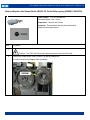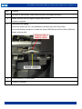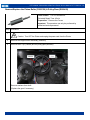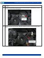
1
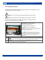
15370 Barranca Parkway
Irvine, CA 92618-2215
USA
FARGO® DTC1000Me-DTC1250e-DTC4250e-DTC4500e
Card Printer Service Manual
PLT-01543 Rev 1.0
November 2013
© 2013 HID Global Corporation/ASSA ABLOY AB. All rights reserved.
DTC1000Me-1250e-4250e-4500e Card Printer Service Manual PLT-01543 rev 1.0
Revision History
Date
Description
Document Version
10-2013
DTC1000Me-1250e-4250e-4500e Card Printer Service Manual
1.0
North America
Europe, Middle East and
Africa
15370 Barranca Parkway,
Irvine, CA 92618,
USA
Phoenix Road,
Haverhill, Suffolk CB9 7AE,
England
866 607-7339, #6
+44 1440 711 822
M-F 7am-6pm CST
M-TH 8:30 - 17:30 GMT
(FR 8:30 - 17:00)
Asia Pacific
Brazil
19/F 625 King’s Road,
Av Guido Caloi 1985 Prédio 18
North Point, Island East,
São Paulo – SP,
Hong Kong
CEP : 05802-140
+852 3160 9833
55 11 5514-7110
M-F 9am – 6pm GMT +8
M-F 9am – 6pm ATC
support.hidglobal.com
www.hidglobal.com
HID GLOBAL, HID, the HID logo, DTC and FARGO are the trademarks or registered trademarks of HID Global
Corporation, or its licensors, in the U.S. and other countries.
November 2013
.
2
DTC1000Me-1250e-4250e-4500e Card Printer Service Manual PLT-01543 rev 1.0
FARGO® DTC1000Me-DTC1250e-DTC4250e-DTC4500e ............................................................................ 1
Card Printer Service Manual ....................................................................................................................... 1
Introduction.................................................................................................................................................. 5
Safety Messages (review carefully) ............................................................................................................ 6
Tools need for DTC Card Printer repair- replacement procedures ................................................................................ 7
Cover Removal Procedures ........................................................................................................................ 8
Remove/Replace Printer Covers DTC 1000Me- 1250e Single Side .............................................................................. 8
DTC Flipper SHORT Dual-Sided Printing Module Removal ........................................................................................ 10
DTC1250e DUAL - DTC4250e Single Printer Cover Removal .................................................................................... 14
DTC4500e Single Side Printer Cover Removal ........................................................................................................... 20
DTC4500e Lamination Module Cover Removal ........................................................................................................... 26
Complete Lamination Module Removal ................................................................................................................... 30
Parts Replacement- Printer ....................................................................................................................... 32
Remove/Replace the Mainboard .................................................................................................................................. 32
Remove/Replace the Display Assembly (MDP-00093 DTC4250e/4500e) .................................................................. 34
(MDP-00059 DTC1250e).............................................................................................................................................. 34
Remove/Replace the Stepper Motor D930027, Stepper Belt F000424, Pulley D900430 ........................................... 36
Remove/Replace the Mag Roller (D930122) ............................................................................................................... 42
Remove/Replace the Output Roller (D930123) Pinch Roller-spring (D920013-F000338) .......................................... 45
Remove/Replace the Platen Roller (D930120) & Pulley/Gear (D900429) ................................................................... 47
Remove/Replace the Lift Pinch Roller Assembly (D930137) Pinch Lift Bracket (D930136) ....................................... 50
Remove/Replace the Cleaning Roller (D930121), Input Feed Lever (D930132), ....................................................... 55
Input Lever Gear (D930164) ........................................................................................................................................ 55
Remove/Replace Supply Spindle RFID Motor ............................................................................................................. 58
Remove/Replace Ribbon Take-Up Motor (D930014) .................................................................................................. 60
Remove/Replace Encoder Sensor (A930514) for RFID Supply Spindle ..................................................................... 62
Remove/Replace the PCB board (A000365-01) .......................................................................................................... 66
Remove/Replace Ribbon Sensor (D930016) ............................................................................................................... 67
Remove/Replace Card Path/Cover Sensor (D930613) ............................................................................................... 71
Parts Replacement - Dual-Sided Printing Module ................................................................................... 73
Remove/Replace the Flipper Cover ............................................................................................................................. 74
Remove/Replace the Flipper Table (D930011) ............................................................................................................ 77
Remove/Replace the Flipper Feed Roller (D930149), Pinch Roller D920013 & F000338) ......................................... 81
Pinch Roller Gears (D30165 & D930166) .................................................................................................................... 81
Remove/Replace the Flipper Assembly Stepper Motor – E001192 ............................................................................. 84
Remove/Replace the Headlift Sensor/Cable- D900113 ............................................................................................... 85
Remove/Replace the IR Sensors D930609 (short) D930614 (tall) .............................................................................. 86
Remove/Replace the PCB Output Controller -A930503 .............................................................................................. 87
Parts Replacement- Lamination Module .................................................................................................. 88
Remove/Replace the Lamination Module Mainboard .................................................................................................. 88
Remove/Replace the Lamination Head Assembly ................................................................................... 90
Upper Assembly (D920022) & Lower Assembly (D920023) ........................................................................................ 90
Remove/Replace the Lamination Module Rollers ........................................................................................................ 95
Remove/Replace the Rewind Motor Assembly RFID Board A000365-01 ................................................................. 107
Encoder Sensor A000126 .......................................................................................................................................... 107
Appendix A............................................................................................................................................... 111
Replacing the DTC Printhead ..................................................................................................................................... 111
DTC Printhead procedure ...................................................................................................................................... 112
Appendix B............................................................................................................................................... 124
Printer Mainboard connections ................................................................................................................................... 124
November 2013
.
3
DTC1000Me-1250e-4250e-4500e Card Printer Service Manual PLT-01543 rev 1.0
Appendix C............................................................................................................................................... 127
Lamination Module Mainboard connections ............................................................................................................... 127
Upper Sensing Cables ........................................................................................................................................... 127
Feed & Lower Sensing Cables .............................................................................................................................. 128
Upper Lam Head Cables........................................................................................................................................ 129
Lower Lam Head Cables........................................................................................................................................ 130
Lower Motor Cables ............................................................................................................................................... 131
Upper RFID and Ribbon Cable .............................................................................................................................. 132
Appendix D............................................................................................................................................... 133
Engineering Drawings ............................................................................................................................................ 133
November 2013
.
4
DTC1000Me-1250e-4250e-4500e Card Printer Service Manual PLT-01543 rev 1.0
Introduction
The service manual serves to inform the technician about the DTC Card Printer & Dual-Sided Printing Module
& Lamination Module parts replacement procedures.
Important: These procedures can only be performed by authorized service personnel.
Estimated repair time may vary according to the technician’s experience.
Caution: Turn OFF the Printer and unplug the power cord from the Printer.
ESD precautions are necessary when handling electronics assemblies
Danger: Wear proper eye protection to perform the procedures in this section.
.
November 2013
.
5
DTC1000Me-1250e-4250e-4500e Card Printer Service Manual PLT-01543 rev 1.0
Safety Messages (review carefully)
The purpose of this section is to provide the User with specific replacement procedures for the Card Printer.
Please review standard precautions (to take) while performing these replacement procedures.
Symbol
Critical Instructions for Safety purposes
Danger:
Failure to follow these installation guidelines can result in death or serious injury.
Information that raises potential safety issues is indicated by a warning symbol (as shown
to the left).
To prevent personal injury, refer to the following safety messages before performing an
operation preceded by this symbol.
To prevent personal injury, always remove the power cord prior to performing repair
procedures, unless otherwise specified.
To prevent personal injury, make sure only authorized service personnel perform these
procedures.
Caution:
This device is electrostatically sensitive. It can be damaged if exposed to static electricity
discharges.
Information that raises potential electrostatic safety issues is indicated by a warning symbol
(as shown to the left).
To prevent equipment or media damage, refer to the following safety messages before
performing an operation preceded by this symbol.
To prevent equipment or media damage, observe all established Electrostatic Discharge
(ESD) procedures while handling cables in or near the Circuit Board and Printhead
Assemblies
To prevent equipment or media damage, always wear an appropriate personal grounding
device (e.g., a high quality wrist strap grounded to avoid potential damage).
To prevent equipment or media damage, always remove the Ribbon and Cards from the
Printer before making any repairs, unless otherwise specified.
To prevent equipment or media damage, take jewelry off of fingers and hands, as well as
thoroughly clean hands to remove oil and debris before working on the Printer.
November 2013
.
6
DTC1000Me-1250e-4250e-4500e Card Printer Service Manual PLT-01543 rev 1.0
Tools need for DTC Card Printer repair- replacement procedures
T10 Torx screwdriver
E Clip tool
Small flathead screwdriver
Needle Nose Pliers
(NOTE: HID Global offers a kit that contains many of the tools needed to repair the printers.
Part Number 085627)
November 2013
.
7
DTC1000Me-1250e-4250e-4500e Card Printer Service Manual PLT-01543 rev 1.0
Cover Removal Procedures
Remove/Replace Printer Covers DTC 1000Me- 1250e Single Side
Tools needed: T10 Torx screwdriver
Estimated Repair Time: 15 minutes
Preparation:
Important: This procedure can only be performed by
authorized service personnel.
DTC1250e
DTC1250e single side shown
Step
DTC1000Me
Top Cover/PCB Assy
D930034-02
D930034-02
Front Door
D930265-05
D930265-04
Left Cover
D930263-03
D930263-02
Right Cover
D930264-03
D930264-02
Output Bin
D930269-01
D930269-01
Procedure
1
Caution: Turn OFF the Printer and unplug the power cord from the Printer.
2
Open the front door. Locate and remove the 2 screws. (F000178)
3
Lift up the top cover and disconnect the display cable (D930607) from the mainboard.
Remove the top cover by flexing the center to disengage the insert tabs.
November 2013
.
8
DTC1000Me-1250e-4250e-4500e Card Printer Service Manual PLT-01543 rev 1.0
Step
Procedure
4
Remove the 2 screws (F000178) that hold the side covers to the frame.
5
Remove both side covers. The input and output hoppers are attached to the side covers.
6
Remove the 2 screws on the bottom right and left side to remove the inner back cover.
Left side
7
Lift UP the bottom of this cover to release the upper tabs that hold the cover to the frame.
8
Procedure is complete.
November 2013
.
Right side
9
DTC1000Me-1250e-4250e-4500e Card Printer Service Manual PLT-01543 rev 1.0
DTC Flipper SHORT Dual-Sided Printing Module Removal
Complete Short Flipper Assembly
D930010-04
DTC1250e Dual side
D930010-06
DTC4250e & 4500e Short Flipper
DTC4250e
DTC1250e Dual
Tools needed: T10 Torx screwdriver
Estimated Repair Time: 15 minutes
Preparation:
Important: This procedure can only be performed by
authorized service personnel.
DTC1250e
DTC4250e
DTC4500e
Top Cover only
D930192-03
If the Dual-Sided Printing Module needs to be
removed for any Printer Replacement procedures
or to remove the covers follow this procedure.
Step
D930192-01
D930192-01
Flipper Front Door only
D930194-01
D930194-01
D930194-01
Procedure
1
Caution: Turn OFF the Printer and unplug the power cord from the Printer.
November 2013
.
10
DTC1000Me-1250e-4250e-4500e Card Printer Service Manual PLT-01543 rev 1.0
Step
2
Procedure
Remove the Top Cover first in order to access the Flipper Module screw attachment.
From the back of the printer locate and remove the 2 screws and washers.
3
Remove the Top Cover.
Unsnap the release tabs located on the back of the printer.
Lift the Top Cover from the front edge and tilt up, back and off.
November 2013
.
11
DTC1000Me-1250e-4250e-4500e Card Printer Service Manual PLT-01543 rev 1.0
Step
4
Procedure
Remove one (1) screw (F000178) that attaches the Flipper Module to the Printer.
Detach the cable from J23 on the mainboard.
November 2013
.
12
DTC1000Me-1250e-4250e-4500e Card Printer Service Manual PLT-01543 rev 1.0
Step
5
Procedure
Tilt the Flipper Module back to release the 3 tabs from the bottom of the printer;
NOTE: Your printer may or may not have screws holding the Module to the Printer depending on the
serial number.
6
Procedure complete
November 2013
.
13
DTC1000Me-1250e-4250e-4500e Card Printer Service Manual PLT-01543 rev 1.0
DTC1250e DUAL - DTC4250e Single Printer Cover Removal
(NOTE: Use this procedure for removing the covers of the DTC1250e DUAL & DTC4250e printer cover
AFTER the Dual-Sided Printing Module has been removed.)
DTC1250e DUAL
Tools needed: T10 Torx screwdriver
Estimated Repair Time: 15 minutes
Preparation:
Important: This procedure can only be performed by
authorized service personnel.
DTC1250e DUAL
DTC4250e Single
November 2013
.
DTC4250e
Top Cover D930181-03
D930181-01
Front Door D930183-03
D930183-04
Output Cover
N/A
D930281-01
Display Cover –blank D930189-03
D930189-01
Display Cover/PCB MDP-00059
MDP-00093
Output Bin
D930333
100 Card Input D930022
D930022
14
DTC1000Me-1250e-4250e-4500e Card Printer Service Manual PLT-01543 rev 1.0
Step
Procedure
1
Caution: Turn OFF the Printer and unplug the power cord from the Printer.
2
From the back of the printer locate and remove the 2 screws and washers.
3
Remove the Top Cover.
Unsnap the release tabs located on the back of the printer.
Lift the Top Cover from the front edge and tilt up and back.
November 2013
.
15
DTC1000Me-1250e-4250e-4500e Card Printer Service Manual PLT-01543 rev 1.0
Step
4
Procedure
To Remove the Display:
With the Top Cover removed, unsnap the display by pivoting from the top DOWN to release the
bottom tabs.
Remove the ribbon cable from the mainboard.
5
Remove the screw holding the card input hopper to the frame.
November 2013
.
16
DTC1000Me-1250e-4250e-4500e Card Printer Service Manual PLT-01543 rev 1.0
Step
Procedure
6
Remove the Input Hopper by tilting back and away from the frame. There are tabs at the bottom that
hold the hopper to the frame.
7
Remove the screw that holds the Output Cover in place.
8
Tilt down and remove the Output Cover.
November 2013
.
17
DTC1000Me-1250e-4250e-4500e Card Printer Service Manual PLT-01543 rev 1.0
Step
Procedure
9
Remove the outer back cover by releasing the tabs on the right and left side.
Tilt cover down to release the bottom tabs.
November 2013
.
18
DTC1000Me-1250e-4250e-4500e Card Printer Service Manual PLT-01543 rev 1.0
Step
Procedure
10
Remove the 2 screws on the bottom right and left side to remove the inner back cover.
Right Side
12
Lift UP the bottom of this cover to release the upper tabs that hold the cover to the frame.
13
Reverse assembly instructions for replacing the covers.
November 2013
.
Left Side
19
DTC1000Me-1250e-4250e-4500e Card Printer Service Manual PLT-01543 rev 1.0
DTC4500e Single Side Printer Cover Removal
Tools needed: T10 Torx screwdriver
Estimated Repair Time: 15 minutes
Preparation:
Important: This procedure can only be performed by
authorized service personnel.
DTC4500e
Top Cover
D930181-01
Display Cover/PCB/cable
MDP-00093
Output Cover
D930281-01
Output Bin
D930033
Dual Input Hopper
D930039
Front Cartridge/Handle Cover MDP-00102
Step
Procedure
1
Caution: Turn OFF the Printer and unplug the power cord from the Printer.
2
Remove the card output hopper. Squeeze in from the top to unlatch the tabs.
November 2013
.
20
DTC1000Me-1250e-4250e-4500e Card Printer Service Manual PLT-01543 rev 1.0
Step
Procedure
3
From the back of the printer locate and remove the 2 screws and washers.
4
Remove the Top Cover.
Unsnap the release tabs located on the back of the printer.
Lift the Top Cover from the front edge and tilt up and back.
November 2013
.
21
DTC1000Me-1250e-4250e-4500e Card Printer Service Manual PLT-01543 rev 1.0
Step
5
Procedure
NOTE: In some cases you may need to remove the Display.
Unsnap the display by pivoting from the top DOWN to release the bottom tabs.
Remove the ribbon cable from the mainboard.
6
Remove the screw (F000178) holding the card Input Hopper to the frame.
November 2013
.
22
DTC1000Me-1250e-4250e-4500e Card Printer Service Manual PLT-01543 rev 1.0
Step
Procedure
7
Remove 2 screws (F000178) from the bottom of the Printer.
Release the cable connection.
8
Remove the Input Hopper by tilting back and away from the frame. There are tabs at the bottom that
hold the hopper to the frame.
9
Remove the screw that holds the Output Cover in place.
November 2013
.
23
DTC1000Me-1250e-4250e-4500e Card Printer Service Manual PLT-01543 rev 1.0
Step
Procedure
10
Tilt down and remove the Output Cover.
11
Remove the Back Cover.
Remove the 2 screws and washers.
Release for 2 tabs at the front and tilt back to release.
November 2013
.
24
DTC1000Me-1250e-4250e-4500e Card Printer Service Manual PLT-01543 rev 1.0
Step
Procedure
12
Lift UP the bottom of this cover to release the upper tab locks that hold the cover to the frame.
13
Reverse assembly instructions for replacing the covers.
November 2013
.
25
DTC1000Me-1250e-4250e-4500e Card Printer Service Manual PLT-01543 rev 1.0
DTC4500e Lamination Module Cover Removal
NOTE: Remove the Lamination Module prior to removing the printer covers if repairing the PRINTER. The
Lamination Module does not need to be removed in order to repair the Lamination Module (unless replacing
the Lamination Mainboard).
Tools needed: T10 Torx screwdriver
Estimated Repair Time: 15 minutes
Preparation:
Important: This procedure can only be performed by
authorized service personnel.
Step
Procedure
1
Caution: Turn OFF the Printer and unplug the power cord from the Printer.
2
Remove the card output bin (D930296-01)
3
Remove the Input Bump Cover (D930292-02)
November 2013
.
26
DTC1000Me-1250e-4250e-4500e Card Printer Service Manual PLT-01543 rev 1.0
Step
Procedure
4
Lift up the Top Cover (D930294-01) to unsnap it from the module.
5
Open from front door.
Unsnap to loosen the 2 side tabs located on either side of the Lam Input Cover (D930290-01)
(It is not necessary to remove the Lam Input assembly to remove this front plate.)
Tilt the Lam Input Cover outward and slide UP to remove. NOTE: Tab Inserts
November 2013
.
27
DTC1000Me-1250e-4250e-4500e Card Printer Service Manual PLT-01543 rev 1.0
Step
Procedure
6
Open the Flipper Door. Remove the 2 screws (F000178) from the left side.
Picture shows door removed, but not necessary for Lamination cover removal.
7
Remove 1 screw (F000178) from the blue retainer clip (D930077).
Disconnect the Flipper Cable ( D930626)
November 2013
.
28
DTC1000Me-1250e-4250e-4500e Card Printer Service Manual PLT-01543 rev 1.0
Step
Procedure
8
Unsnap the Lam Back Cover (D930293-02) panel from the bottom and lift up to remove.
Make NOTE: of the latches holding these together when replacing it.
9
Remove the Front Lam Door Cover (D930291-01) by flexing the door IN, release the top and bottom
pins holding the door to the frame.
10
Remove the 4 screws that hold the Front Lam Cover (D930289-01) to the frame.
11
Procedure complete
November 2013
.
29
DTC1000Me-1250e-4250e-4500e Card Printer Service Manual PLT-01543 rev 1.0
Complete Lamination Module Removal
1
If the Lamination Module needs to be removed from the printer completely then turn the printer over
and unscrew the 2 screws that attach the Lamination Module to the printer.
2
Remove the screw (F000178) from the Retainer Clip (D930077) that holds the Lamination Module to
the Printer.
Disconnect the Flipper Cable ( D930626)
November 2013
.
30
DTC1000Me-1250e-4250e-4500e Card Printer Service Manual PLT-01543 rev 1.0
Step
Procedure
3
Set the printer upright and move to the edge of the table. Unclip the tabs from below and move the
module outward. This will release the PCB connection within the door.
NOTE: When replacing the module carefully line up the PCB connection; push the module onto the
printer base to connect the PCB. Do not force or bend pins.
4
Procedure is complete. Reverse assembly to reinstall the Lamination Module.
November 2013
.
31
DTC1000Me-1250e-4250e-4500e Card Printer Service Manual PLT-01543 rev 1.0
Parts Replacement- Printer
Remove/Replace the Mainboard
Tools needed: T10 Torx screwdriver
Estimated Repair Time: 20 min
Preparation: Remove the Covers
Important: This procedure can only be performed by
authorized service personnel.
DTC1000Me
PCA-00106
DTC1250e
PCA-00102 NA
AP=APAC
DTC1250e
PCA-00103 AP
FD=Flipper Dual
DTC1250e
PCA-00104 FD NA
Check the printer label to order the
correct board.
DTC1250e
PCA-00105 FD AP
DTC4250e
PCA-00107
DTC4500e
PCA-00109
NOTE: : NA=Non-APAC
Step
Procedure
1
Caution: Turn OFF the Printer and unplug the power cord from the Printer.
2
Remove the covers to access the mainboard.
Remove all the wire connections from the Mainboard.
3
Remove the 2 screws (F000178) shown. The center open hole is for the frame peg.
November 2013
.
32
DTC1000Me-1250e-4250e-4500e Card Printer Service Manual PLT-01543 rev 1.0
Step
Procedure
4
Slide board out from the corner posts
5
Install new board and reconnect all wires.
Wires are labeled for location connection.
6
Procedure is complete.
November 2013
.
33
DTC1000Me-1250e-4250e-4500e Card Printer Service Manual PLT-01543 rev 1.0
Remove/Replace the Display Assembly (MDP-00093 DTC4250e/4500e)
(MDP-00059 DTC1250e)
Contains Cover, PCB, LCD Buttons and Cable
The same procedure is used for either orientation of the LCD Display.
Tools needed: T10 Torx screwdriver
Estimated Repair Time: 15 min
Preparation: Remove Top Cover
Important: This procedure can only be performed by
authorized service personnel.
MDP-00093
LCD PCB (board only) DTC4250e 4500e
LCD PBC (board only) DTC 1250e
A930507-01
A930507
MDP-00059
Step
Procedure
1
Caution: Turn OFF the Printer and unplug the power cord from the Printer.
2
Remove the top cover of the printer.
3
Pull forward on the display to un-snap from the bottom of the display. Lift out to remove.
4
Remove the ribbon cable (D930607)
(Also from the LCD PCB A930507-01-DTC4250e/4500e).
November 2013
.
34
DTC1000Me-1250e-4250e-4500e Card Printer Service Manual PLT-01543 rev 1.0
Step
5
Procedure
Install completed assembly.
Do not pinch the cable when replacing.
Pull cable taught when replacing.
6
Procedure is complete.
November 2013
.
35
DTC1000Me-1250e-4250e-4500e Card Printer Service Manual PLT-01543 rev 1.0
Remove/Replace the Stepper Motor D930027, Stepper Belt F000424, Pulley D900430
Tools needed: T10 Torx screwdriver
E CLIP tool
Estimated Repair Time: 30 min
Preparation: Remove the Covers
Important: This procedure can only be performed by
authorized service personnel.
Part Number: Complete Stepper Drive assembly
D930028
Step
Procedure
1
Caution: Turn OFF the Printer and unplug the power cord from the Printer.
2
Remove Covers.
3
Lay printer on its front.
Remove the cable harness (D930600) from the Stepper Motor.
November 2013
.
36
DTC1000Me-1250e-4250e-4500e Card Printer Service Manual PLT-01543 rev 1.0
Step
4
Procedure
Remove the 3 screws that hold the Motor/Mount to the printer frame. (Make NOTE: of where the 2
screw/washers go and the one machine screw. Remove the printhead cable for more clearance)
The motor is attached to a plastic mounting frame.
5
Remove the 4 screws that hold the stepper motor to the mount frame.
One belt (F000424) will come off of the platen roller pulley/gear (D900429).
(Caution: Spring may pop out. Safety glasses required)
November 2013
.
37
DTC1000Me-1250e-4250e-4500e Card Printer Service Manual PLT-01543 rev 1.0
Step
6
Procedure
If replacing the Pulley D900430 remove the E CLIP (140063).
Replace with new Pulley.
Re-install the E-clip.
7
Replace the new Motor to the mount frame.
Make sure Spring (F000332) gets put back into proper place
8
Install the belt (F000424)
November 2013
.
38
DTC1000Me-1250e-4250e-4500e Card Printer Service Manual PLT-01543 rev 1.0
Step
9
Procedure
This Stepper Motor Mount provides a self tensioning feature.
Keep the four (4) screws loose while holding the Mount Frame.
Allow the spring to self-tension, then tighten the four (4) screws.
10
Install belt on stepper motor assembly and then loop the belt w/stepper drive assembly around the
platen roller shaft gear.
Place the Stepper Mount over the pivot peg.
November 2013
.
39
DTC1000Me-1250e-4250e-4500e Card Printer Service Manual PLT-01543 rev 1.0
Step
Procedure
11
Fit the Mount behind the tab on the printers side plate frame. This locks the mount in place.
12
Secure the stepper drive assembly with 2 screws (F000171) with 2 washers (140040), and one screw
(F000178) at the specific locations shown.
NOTE: Lightly tighten all screws first then tighten the (F000171) screws last.
November 2013
.
40
DTC1000Me-1250e-4250e-4500e Card Printer Service Manual PLT-01543 rev 1.0
Step
Procedure
13
Plug motor cable back in.
Replace the Printhead cable if it was removed in step 4.
14
Procedure is complete.
November 2013
.
41
DTC1000Me-1250e-4250e-4500e Card Printer Service Manual PLT-01543 rev 1.0
Remove/Replace the Mag Roller (D930122)
Tools needed: Small flat screwdriver, T10 Torx screwdriver
Estimated Repair Time: 20 min
Preparation: Remove the Covers
Important: This procedure can only be performed by
authorized service personnel.
Step
Procedure
1
Caution: Turn OFF the Printer and unplug the power cord from the Printer.
2
Remove the Stepper Motor Assembly (D930028)
Remove the 3 screws that hold the Motor/Mount to the printer frame. (Make NOTE: of where the 2
screw/washers go and the one machine screw. Remove the printhead cable for more clearance.)
The motor is attached to a plastic mounting frame.
November 2013
.
42
DTC1000Me-1250e-4250e-4500e Card Printer Service Manual PLT-01543 rev 1.0
Step
3
4
Procedure
Remove the Mag Roller Gear (D930361) by pulling out.
Remove the Ribbon Deflector Plate (D930129) to access the Mag Roller. Release the tabs that
hold the plate in place.
5
Pull the Mag Roller out from the front side of the printer.
November 2013
.
43
DTC1000Me-1250e-4250e-4500e Card Printer Service Manual PLT-01543 rev 1.0
Step
6
Procedure
Replace with the new roller.
Install the Mag Roller from the back to hold the roller in place.
Make sure roller sits in front tab (hidden) in front sideplate.
Make sure tabs line up and snap into place. Wiggle in place.
NOTE: Do not hold the roller by the rubber but only from the plastic shaft. The rubber can move out
of position on the shaft and cause a print quality issue.
7
Install the Ribbon Deflector Plate.
8
Re-install Stepper Motor assembly
9
Procedure is complete.
November 2013
.
44
DTC1000Me-1250e-4250e-4500e Card Printer Service Manual PLT-01543 rev 1.0
Remove/Replace the Output Roller (D930123) Pinch Roller-spring (D920013-F000338)
Tools needed: T10 Torx screwdriver
Estimated Repair Time: 20 min
Preparation: Remove the Covers
Important: This procedure can only be performed by
authorized service personnel.
Step
Procedure
1
Caution: Turn OFF the Printer and unplug the power cord from the Printer.
2
Remove the Output Roller Gear (D930361) by pulling straight out.
No need to remove the Stepper Motor Assembly.
November 2013
.
45
DTC1000Me-1250e-4250e-4500e Card Printer Service Manual PLT-01543 rev 1.0
Step
Procedure
3
Flip printer on front remove Output Roller (D930123) Pull straight up and out
4
Replace with new roller and replace the gear onto the roller.
Procedure completed.
5
Pinch Roller and Spring
Remove the output roller first ( as stated above) and then remove the Pinch Roller
Use a small flathead screwdriver to release the spring (F000338) and the Pinch Roller (D920013).
Replace with new roller.
6
Reverse assembly to reinstall parts.
7
Procedure is complete.
November 2013
.
46
DTC1000Me-1250e-4250e-4500e Card Printer Service Manual PLT-01543 rev 1.0
Remove/Replace the Platen Roller (D930120) & Pulley/Gear (D900429)
Tools needed: T10 Torx screwdriver
Estimated Repair Time: 45 min
Preparation: Remove the Covers
Important: This procedure can only be performed by
authorized service personnel.
Step
Procedure
1
Caution: Turn OFF the Printer and unplug the power cord from the Printer.
2
Remove the Stepper Motor Assembly (E000062)
3
Remove the E Clip (140048) and the pulley/gear(D900429)
Remove washers from shaft.
(Replace the gear if necessary)
November 2013
.
47
DTC1000Me-1250e-4250e-4500e Card Printer Service Manual PLT-01543 rev 1.0
Step
Procedure
4
Turn the twist lock Bushing-Twist Lock (D930178) counter clockwise to unlock and lift up. It is not
necessary to remove the surrounding gears.
5
Remove the Platen Cam (D930135). Rotate cam clockwise to remove. Pull off of the Platen Roller
Shaft.
November 2013
.
48
DTC1000Me-1250e-4250e-4500e Card Printer Service Manual PLT-01543 rev 1.0
Step
6
Procedure
Remove the print head assembly if better access is needed.
See Printhead removal procedure Replacing the DTC Printhead.
7
Move the lever up to clear the Platen Roller (D930120)
8
Replace with new roller.
9
Reverse assembly to reinstall parts.
10
Procedure is complete.
November 2013
.
49
DTC1000Me-1250e-4250e-4500e Card Printer Service Manual PLT-01543 rev 1.0
Remove/Replace the Lift Pinch Roller Assembly (D930137) Pinch Lift Bracket (D930136)
Tools needed: T10 Torx screwdriver
Estimated Repair Time: 20 Min
D930137
Preparation: . Remove the Covers
Important: This procedure can only be performed by
authorized service personnel.
D930136
Step
Procedure
1
Caution: Turn OFF the Printer and unplug the power cord from the Printer.
2
Remove the mainboard (D930500)
3
Pull the tabs apart on the Bracket (D930136) to release. Lift up and out.
November 2013
.
50
DTC1000Me-1250e-4250e-4500e Card Printer Service Manual PLT-01543 rev 1.0
Step Procedure
4
Rotate the Lift Bracket (D930136) with the spring (D930266) upwards to disengage the hinge.
5
Lift out the Pinch Roller Bracket (D930137).
NOTE: Verify orientation when re installing.
6
Replace with new Platen Roller.
Lock platen with cam first into the front sideplate.
November 2013
.
51
DTC1000Me-1250e-4250e-4500e Card Printer Service Manual PLT-01543 rev 1.0
Step
7
Procedure
To reinstall the Pinch Roller Assembly:
a. Verify orientation of the Pinch Roller Assembly
b. Connect the spring to the bracket.
Continued next page
c. Insert the Bracket tabs into the holes provided in the sideplate frame.
(continued on next page)
November 2013
.
52
DTC1000Me-1250e-4250e-4500e Card Printer Service Manual PLT-01543 rev 1.0
d. Tilt the spring upward and fit in to the slot provided. Some force is needed to snap the spring
and tabs in place.
e. Click the Bracket into the frame.
f. Snap the Roller Bracket tabs to the Lift Bracket.
(continued on next page)
November 2013
.
53
DTC1000Me-1250e-4250e-4500e Card Printer Service Manual PLT-01543 rev 1.0
g. Procedure is complete.
November 2013
.
54
DTC1000Me-1250e-4250e-4500e Card Printer Service Manual PLT-01543 rev 1.0
Remove/Replace the Cleaning Roller (D930121), Input Feed Lever (D930132),
Input Lever Gear (D930164)
Tools needed: T10 Torx screwdriver
Estimated Repair Time: 30 min
D930121
Preparation: Remove the Covers
Important: This procedure can only be performed by
authorized service personnel.
Step
Procedure
1
Caution: Turn OFF the Printer and unplug the power cord from the Printer.
2
Remove the ribbon supply assembly.
3
Remove the mainboard (D930500)
4
Remove the screw F000178 & washer 140040 from the motor assembly. This is done from the
front of the printer.
NOTE: This step is used for the DTC 1250e, 1000Me, 4250e
5
Slide the Supply Spindle DOWN To release. Slide the Motor UP to install.
NOTE: You do not need to remove the gears or the Stepper Motor for this procedure.
November 2013
.
55
DTC1000Me-1250e-4250e-4500e Card Printer Service Manual PLT-01543 rev 1.0
Step
Procedure
NOTE: This step is used for the DTC 1250e, 1000Me, 4250e.
6
Remove the Cleaning Roller Gear (D930361)
7
Remove the stepper motor assembly and belt (D930028)
8
Remove the pulley (e-clip) and washers.
9
Remove platen cam rotation. Locking bushing.
10
Remove the Lever. Be careful not to lose the spring.
NOTE: How the spring is set into the pegs.
The gear will pull straight out.
November 2013
.
56
DTC1000Me-1250e-4250e-4500e Card Printer Service Manual PLT-01543 rev 1.0
Step
11
Procedure
From the front of the printer release the cleaning roller from the peg by pushing all the way back
and dropping the roller.
NOTE: Do not hold the roller by the rubber but only from the plastic shaft. The rubber can move
out of position on the shaft and cause a print quality issue.
12
Replace with new roller.
13
Insert the Spring into the upper and lower pegs.
Install the Lever then the Gear.
Turn the black platen gear to verify the gears turn simultaneously.
14
Reinstall cam, locking bushing, stepper motor, ribbon supply assembly.
15
Procedure is complete.
November 2013
.
57
DTC1000Me-1250e-4250e-4500e Card Printer Service Manual PLT-01543 rev 1.0
Remove/Replace Supply Spindle RFID Motor
Tools needed: T10 Torx screwdriver
Estimated Repair Time: 20 min
Preparation: Remove the Covers
Important: This procedure can only be performed by
authorized service personnel.
Step
Procedure
1
Caution: Turn OFF the Printer and unplug the power cord from the Printer.
2
Remove the screw F000178 & washer 140040 from the motor assembly. This is done from the front
of the printer.
NOTE: DTC1250e/4250e will have 2 screws holding the Supply. DTC4500e has only one screw
holding the supply.
November 2013
.
58
DTC1000Me-1250e-4250e-4500e Card Printer Service Manual PLT-01543 rev 1.0
Step
3
Procedure
Slide the Supply Spindle DOWN To release. Slide the Motor UP to install.
NOTE: You do not need to remove the gears or the Stepper Motor for this procedure.
NOTE: If ribbon wrinkle occurs after replacing the motor, move the motor assembly DOWN slightly in
the frame. Loosen the 2- F000178 screws from the supply spindle, move down 1/16th inch then
tighten the F000178 screws.
4
Remove the RFID cable (D930603) from the Supply Spindle.
Remove the Encoder Sensor cable harness (D930600) from the encoder sensor.
NOTE: The routing of these wires under the clip.
5
Replace the complete assembly Motor.
Reconnect wires.
6
Procedure is complete.
November 2013
.
59
DTC1000Me-1250e-4250e-4500e Card Printer Service Manual PLT-01543 rev 1.0
Remove/Replace Ribbon Take-Up Motor (D930014)
Tools needed: T10 Torx screwdriver
Estimated Repair Time: 20 min
Preparation: Remove the Covers
Important: This procedure can only be performed by
authorized service personnel.
D930014
Step
Procedure
1
Caution: Turn OFF the Printer and unplug the power cord from the Printer.
2
Remove the screw (F000178) & washer (140040) from the motor assembly.
This is done from the front of the printer.
3
Slide the Take-Up Motor DOWN to release. Slide the Motor UP to install.
NOTE:: You do not need to remove the gears or the Stepper Motor for this procedure.
November 2013
.
60
DTC1000Me-1250e-4250e-4500e Card Printer Service Manual PLT-01543 rev 1.0
Step
4
Procedure
Remove the wire connection (D930600) harness from the top of the Take-Up Motor.
5
Replace the complete assembly Motor.
6
Reconnect wires.
7
Procedure is complete.
November 2013
.
61
DTC1000Me-1250e-4250e-4500e Card Printer Service Manual PLT-01543 rev 1.0
Remove/Replace Encoder Sensor (A930514) for RFID Supply Spindle
NOTE: For any other parts (motor/ encoder wheel) REPLACE COMPLETE ASSEMBLY (D930015).
Tools needed: Torx screwdriver and flat head screwdriver
Estimated Repair Time: 30 min
Preparation: Remove the Covers
A000365-01
Step
Important: This procedure can only be performed by
authorized service personnel.
RFID Cable
D930603
Encoder Sensor Cable
D930605
Procedure
1
Caution: Turn OFF the Printer and unplug the power cord from the Printer.
2
Remove Supply Spindle-RFID assembly. Refer to: Remove/Replace Supply Spindle RFID Motor
(D930015) DTC4500e OR Remove/Replace Supply Spindle RFID Motor (D930015)
DTC1250e/4250e
November 2013
.
62
DTC1000Me-1250e-4250e-4500e Card Printer Service Manual PLT-01543 rev 1.0
Step
Procedure
3
Remove the Damper Cap (F000487)
Use a thin flathead screwdriver to loosen one side.
The cap will pop off.
NOTE: Replace the Damper Cap by lining up the shaft first then snap the Damper Cap back on.
Verify the gray shaft is pushed up to hold the encoder wheel in place.
November 2013
.
63
DTC1000Me-1250e-4250e-4500e Card Printer Service Manual PLT-01543 rev 1.0
Step
Procedure
4
Remove the supply cover (D930116) by pulling up from the open end.
This will unlatch the tabs holding the cover to the frame.
This allows for access to the sensor.
November 2013
.
64
DTC1000Me-1250e-4250e-4500e Card Printer Service Manual PLT-01543 rev 1.0
Step
Procedure
5
Remove the sensor.
Use a thin flat blade screwdriver to unlatch the tabs holding the sensor to the frame.
6
Press the new sensor into the assembly; make sure the encoder wheel is in between the sensor.
7
Replace with new Sensor (A930514) and/ or Cable (D930605)
8
Line up the sensor with the slot and snap back in.
Reconnect cable to J18
9
Procedure is complete.
November 2013
.
65
DTC1000Me-1250e-4250e-4500e Card Printer Service Manual PLT-01543 rev 1.0
Remove/Replace the PCB board (A000365-01)
Step
Procedure
1
Remove Supply Spindle-RFID assembly. See procedure above (D930015).
Un-snap the PCB from the frame.
The PCB with the HOLES is set under the corner tabs.
Lift up this end first. See picture below.
2
Replace with new PCB and/ or Cable.
3
Insert one end first then snap into the corner tabs. Replace cable to J9.
4
For both procedures route the cables under the holding tab.
5
Reverse assembly to reinstall parts
6
Procedure is complete.
November 2013
.
66
DTC1000Me-1250e-4250e-4500e Card Printer Service Manual PLT-01543 rev 1.0
Remove/Replace Ribbon Sensor (D930016)
Tools needed: T10 Torx screwdriver
Estimated Repair Time: 30 min
Preparation: Remove the Covers
Important: This procedure can only be performed by
authorized service personnel.
Ribbon Sensor Cable only D930608
Step
Procedure
1
Caution: Turn OFF the Printer and unplug the power cord from the Printer.
2
Remove the Stepper Motor assembly first. See steps 4 & 5
3
Remove the Platen Roller Gears (D900429) to access the Ribbon Sensor.
Remove the retaining ring (140048) and pull off the gear.
November 2013
.
67
DTC1000Me-1250e-4250e-4500e Card Printer Service Manual PLT-01543 rev 1.0
Step
4
Procedure
Remove the screw F000178 & washer 140040 from the Stepper Motor assembly. This is done from
the front of the printer.
NOTE: DTC1250e/4250e will have 2 screws holding the Supply. DTC4500e has only one screw
holding the supply.
5
Slide the Supply Spindle DOWN To release. Slide the Motor UP to install.
NOTE: You do not need to remove the gears or the Stepper Motor for this procedure.
NOTE: If ribbon wrinkle occurs after replacing the motor, move the motor assembly DOWN slightly in
the frame. Loosen the 2- F000178 screws from the supply spindle, move down 1/16th inch then
tighten the F000178 screws.
November 2013
.
68
DTC1000Me-1250e-4250e-4500e Card Printer Service Manual PLT-01543 rev 1.0
Step
Procedure
6
Remove the cleaning roller Gear (D930361) to access the Ribbon Sensor.
7
From the front of the printer: Pinch the tabs to help remove the sensor from the frame.
PUSH the Ribbon Sensor back to release the tabs and remove the sensor.
November 2013
.
69
DTC1000Me-1250e-4250e-4500e Card Printer Service Manual PLT-01543 rev 1.0
Step
8
Procedure
Replace with the new sensor. Push the sensor back in using the tabs to snap the sensor in place.
This is done from the rear sideplate of the printer near the gears.
Note: The wire routing to the frame. (Shown unpopulated for viewing )
9
Reverse assembly to reinstall parts. Verify wave washer is in place.
10
Procedure is complete
November 2013
.
70
DTC1000Me-1250e-4250e-4500e Card Printer Service Manual PLT-01543 rev 1.0
Remove/Replace Card Path/Cover Sensor (D930613)
Tools needed: T10 Torx screwdriver
Estimated Repair Time: 30 min
Preparation: Remove the Covers
Important: This procedure can only be performed by
authorized service personnel.
Step
Procedure
1
Caution: Turn OFF the Printer and unplug the power cord from the Printer.
2
Remove the mainboard.
Remove the J11 and J17 connector from the mainboard.
3
Use a small flathead screwdriver to GENTLY pry the sensor up.
The sensor must be released from the small tab holding the sensor.
( See the RED arrow)
NOTE: Pry up on both sides of the sensor legs not just one side or it may break.
(The cable is shown on THIS side of the frame for clarity.)
November 2013
.
71
DTC1000Me-1250e-4250e-4500e Card Printer Service Manual PLT-01543 rev 1.0
Step
Procedure
4
Replace with the new sensor.
Line up the sensor and push down to snap it in place UNDER the small tab.
Route the cable on the right side of the frame as shown in the picture below.
Connect to the mainboard
Reverse assembly to complete the procedure.
November 2013
.
72
DTC1000Me-1250e-4250e-4500e Card Printer Service Manual PLT-01543 rev 1.0
Parts Replacement - Dual-Sided Printing Module
D930010-04 (Short Module) used for DTC1250e Flipper complete assembly
D930010-06 (Short Module) used for DTC4250e & 4500e Flipper complete assembly
MDP-00104 (Tall Module) used for DTC4500e Flipper complete assembly
IMPORTANT NOTE: The Flipper Table should be level when the Printer is powered up. If the Flipper Table is
at an angle, open the access door and manually level it. Then cycle the Printer Power to reset.
Remove all covers to access the Flipper Parts Replacements
November 2013
.
73
DTC1000Me-1250e-4250e-4500e Card Printer Service Manual PLT-01543 rev 1.0
Remove/Replace the Flipper Cover
Tools needed: T10 Torx screwdriver
Estimated Repair Time: 15 min
Preparation: Remove the top cover of the Printer and Dual-Sided Printing
Module from the Printer
Important: This procedure can only be performed by authorized service
personnel.
Short & Tall use common parts
Short Dual-Sided Printing
Module shown
Top cover D930192-01
DTC4250e/4500e
Top Cover D930192-03
DTC1250e
Card Bin
D930193-01
DTC4250e/4500e
Card Bin
D930193-03
DTC1250e
Flipper Door D930194-01
D930010-06
The Tall Dual-Sided Printing Module uses the Lamination Cover
Step
Procedure
1
Caution: Turn OFF the Printer and unplug the power cord from the Printer.
Caution: Please be careful not to force any of the snapping parts as they could break with
too much pressure. When replacing the Covers or any parts, do NOT pinch any wires.
2
Remove the Top Cover of the printer.
Remove the Dual-Sided Printing Module from the printer.
November 2013
.
74
DTC1000Me-1250e-4250e-4500e Card Printer Service Manual PLT-01543 rev 1.0
Step
Procedure
3
Remove the Dual-Sided Printing Module Top Cover.
Grasp the cover from the open end and tilt forward to unlatch the front tabs.
4
Remove the Flipper Base Cover: Turn the module over and use a T10 Torx screwdriver to remove
the 2 screws of the bottom plate.
5
Grasp the module with 2 hands and tilt back and up.
TIP: Use your hand from underneath to push the inner wall OUT for easier release of the tabs.
November 2013
.
75
DTC1000Me-1250e-4250e-4500e Card Printer Service Manual PLT-01543 rev 1.0
Step
Procedure
6
The module is now ready to replace any of the following parts:
Flipper Table with gear and rollers (D930611)
Stepper Motor (E001192) with Gear connects to J5
Stepper Motor (E001192) Cable (D930610)
PCB Output Controller-Main Board (D930503)
Lead Screw Assembly (D930155) used for SHORT Module
Lead Screw Assembly (D930176) used for TALL Module
Lead Screw Assembly Gear used for both Short and Tall (D930106)
Headlift Sensor & cable (D900113) connects to J3 HOME
IR Sensor Pair include Detector (Upper & Lower sensor with cable connects to J4 CARD)
Both IR sensors connect to ONE cable and are replaced at the same time.
(D930609 used for SHORT Module. D930614 used for TALL Module)
Ribbon Cable (D930611) connects Flipper to printer
November 2013
.
76
DTC1000Me-1250e-4250e-4500e Card Printer Service Manual PLT-01543 rev 1.0
Remove/Replace the Flipper Table (D930011)
Tools needed: T10 Torx screwdriver
Estimated Repair Time: 20 min
Preparation: Remove the Covers
Important: This procedure can only be performed by
authorized service personnel.
Step
Procedure
1
Caution: Turn OFF the Printer and unplug the power cord from the Printer.
2
Remove the Covers.
3
Remove the Bushing Screw Twist. Twist to unlock and lift off.
November 2013
.
77
DTC1000Me-1250e-4250e-4500e Card Printer Service Manual PLT-01543 rev 1.0
Step
4
Procedure
Remove the Lead Screw Assembly by pushing UP and pulling OUT from the bottom at an angle.
Short Lead Screw D930155
Tall Lead Screw D930176
November 2013
.
78
DTC1000Me-1250e-4250e-4500e Card Printer Service Manual PLT-01543 rev 1.0
Step
Procedure
5
Remove the one screw that holds the Flipper Table to the Bracket Table Mount
6
Remove the Flipper Table.
7
Reverse assembly to install new Flipper Table.
Verify Lead Screw and Lead Pin is set correctly. Also see step 8 for spring and washer placement.
Push down on the top of the lead screw to set into the gear.
November 2013
.
79
DTC1000Me-1250e-4250e-4500e Card Printer Service Manual PLT-01543 rev 1.0
Step
Procedure
8
Verify the Lead Screw Assembly has the washer and spring in the correct position.
9
Replace the twist lock.
November 2013
.
80
DTC1000Me-1250e-4250e-4500e Card Printer Service Manual PLT-01543 rev 1.0
Remove/Replace the Flipper Feed Roller (D930149), Pinch Roller D920013 & F000338)
Pinch Roller Gears (D30165 & D930166)
Tools needed: T10 Torx screwdriver
Estimated Repair Time: 20 minutes
Preparation: Remove the Covers
Important: This procedure can only be performed by
authorized service personnel.
D930149
D920013 + F000338
D930165 (3 used)
Step
D930166
Procedure
1
Caution: Turn OFF the Printer and unplug the power cord from the Printer.
2
Start with the instruction for replacing the Flipper Table.
November 2013
.
81
DTC1000Me-1250e-4250e-4500e Card Printer Service Manual PLT-01543 rev 1.0
Step
Procedure
3
Remove the Flipper Table from the Base Bracket by pinching the 2 side tabs inward to release the
table from the base.
4
Card Feed Roller (D930149) - Replace with the new Roller. Line up the roller and the tab slots and
push together. Verify the roller spins freely and turns the gears.
November 2013
.
82
DTC1000Me-1250e-4250e-4500e Card Printer Service Manual PLT-01543 rev 1.0
Step
Procedure
5
Pinch Roller (D920013) Insert spring into the roller and line up one end at a time.
6
Gear (D930165 –D930166) placement shown below for pivot bracket.
Verify the assembly is fully snapped together if these are replaced.
7
When re-assembling the table verify the LEAD Screw and gears move freely up and down and can
rotate the table.
8
Replace the Bushing Screw Twist Lock to secure the Lead Screw.
9
Procedure is complete.
November 2013
.
83
DTC1000Me-1250e-4250e-4500e Card Printer Service Manual PLT-01543 rev 1.0
Remove/Replace the Flipper Assembly Stepper Motor – E001192
Tools needed: T10 Torx screwdriver
Estimated Repair Time: 20 min
Preparation: Remove the Covers
Important: This procedure can only be performed by
authorized service personnel.
Stepper Motor Cable (D930610)
Step
Procedure
1
Caution: Turn OFF the Printer and unplug the power cord from the Printer.
2
Remove the Flipper Covers.
3
Disconnect the cable (D930610) from J5 on the PCB.
If replacing this cable make NOTE: of how the wire is routed.
4
Remove the 2 screws (F000178) that hold the motor to the frame.
5
Replace with new motor
6
Procedure is complete
November 2013
.
84
DTC1000Me-1250e-4250e-4500e Card Printer Service Manual PLT-01543 rev 1.0
Remove/Replace the Headlift Sensor/Cable- D900113
Tools needed: T10 Torx screwdriver
Estimated Repair Time: 20 min
Preparation: Remove the Covers
Important: This procedure can only be performed by
authorized service personnel.
Step
Procedure
1
Caution: Turn OFF the Printer and unplug the power cord from the Printer.
2
Remove the Flipper Covers.
3
Pull the Headlift Sensor OUT towards the stepper motor gear to release from the frame. Sensor does
not come out with breaking the sensor or tab.
4
Replace sensor by snapping IN the slot provided.
5
Reverse assembly
6
Procedure is complete
November 2013
.
85
DTC1000Me-1250e-4250e-4500e Card Printer Service Manual PLT-01543 rev 1.0
Remove/Replace the IR Sensors D930609 (short) D930614 (tall)
Tools needed: T10 Torx screwdriver
Estimated Repair Time: 20 min
Preparation: Remove the Covers
Important: This procedure can only be performed by
authorized service personnel.
Step
Procedure
1
Caution: Turn OFF the Printer and unplug the power cord from the Printer.
2
Remove the Flipper Covers.
3
Push the sensor out using some pressure. This sensor snaps in and out. Do not use a metal tool or it
may damage the sensor.
4
Replace both upper and lower sensor at the same time.
5
Connect to J4 on the PCB. Make NOTE: of wire routing.
November 2013
.
86
DTC1000Me-1250e-4250e-4500e Card Printer Service Manual PLT-01543 rev 1.0
Remove/Replace the PCB Output Controller -A930503
Tools needed: T10 Torx screwdriver
Estimated Repair Time: 20 min
Preparation: Remove the Covers
Important: This procedure can only be performed by
authorized service personnel.
Step
Procedure
1
Caution: Turn OFF the Printer and unplug the power cord from the Printer.
2
Remove the Flipper Covers.
3
Disconnect all cable connections
4
Hold the 2 tabs BACK to release the board from the holding tabs.
5
Replace with new board.
6
Procedure is complete
November 2013
.
87
DTC1000Me-1250e-4250e-4500e Card Printer Service Manual PLT-01543 rev 1.0
Parts Replacement- Lamination Module
Remove/Replace the Lamination Module Mainboard
Tools needed: T10 Torx screwdriver
Estimated Repair Time: 20 min
Preparation: Remove the Lamination Module Covers
Important: This procedure can only be performed by
authorized service personnel.
Step
DTC4500e (single side)
A920221-11
DTC4500e (dual side)
A920221-12
Procedure
1
Caution: Turn OFF the Printer and unplug the power cord from the Printer.
2
Remove the Lamination Module from the printer base to access the mainboard.
3
Turn the module up-side down to access the 4 screws (F000178) that hold the mainboard to the
frame. Remove the 4 screws.
Use caution when removing the mainboard so the power connector does not get damaged. Slide the
board away and out from the frame.
November 2013
.
88
DTC1000Me-1250e-4250e-4500e Card Printer Service Manual PLT-01543 rev 1.0
Step
Procedure
4
Remove all the wire connections.
Tilt the mainboard up to access the wires.
Wires are labeled with the numbered location for easy replacement.
(Refer to Appendix B for wire/board locations)
5
Replace with the new mainboard using reverse assembly.
NOTE: Use caution not to damage the power connector.
November 2013
.
89
DTC1000Me-1250e-4250e-4500e Card Printer Service Manual PLT-01543 rev 1.0
Remove/Replace the Lamination Head Assembly
Upper Assembly (D920022) & Lower Assembly (D920023)
Tools needed: T10 Torx screwdriver
Estimated Repair Time: 35 min
Preparation: Remove the Lamination Module Covers.
Remove the mainboard to access the wire removal procedure.
Important: This procedure can only be performed by
authorized service personnel.
This part is sold as one assembly which
includes :
Platen Roller (D920012-Upper),
Lamination Roller (D920020- Lower),
Film LED (A000454)
Head Lift Sensor (A000126)
Thermocouple RTD/cable (D920151)
Motor (D900484-05) and the wires.
Step
Procedure
1
Caution: Turn OFF the Printer and unplug the power cord from the Printer.
2
Both the Upper and Lower Lamination Assemblies follow the same procedure.
November 2013
.
90
DTC1000Me-1250e-4250e-4500e Card Printer Service Manual PLT-01543 rev 1.0
Step
Procedure
3
Remove the Retaining Ring (140048) and Platen Drive Gear ( 810265)
4
Remove the 3 screws (F000182) that hold the assembly to the frame.
Upper Module
Lower Module
November 2013
.
91
DTC1000Me-1250e-4250e-4500e Card Printer Service Manual PLT-01543 rev 1.0
Step
Procedure
5
With the Mainboard loosened and tilted back the wire connections are now accessible.
Locate the Lamination Head Assembly wire connections.
Remove these wires from the mainboard.
Location of Upper Lam Head Cables
Lift Sensor D920156 connects to J4
Heater Cartridge D920113 connects to J9
RTD Cable D920151 connects to J18
Location of Lower Lam Head Cables
Lift Sensor D920156) connects to J21
RTD Sensor Cable D920151 connects to J17
Heater Cartridge Cable D920113 connects to J3
6
Remove the Lamination Module assembly.
Replace with new Lamination Module assembly using reverse assembly procedure.
7
Make NOTE: of how the wires are routed. UPPER ASSEMBLY
(continued next page)
November 2013
.
92
DTC1000Me-1250e-4250e-4500e Card Printer Service Manual PLT-01543 rev 1.0
NOTE: Ensure there is cable slack between the lam head and the upper wire clip to allow free
movement of the lam head. Do not pinch any wires.
8
Make NOTE: of how the wires are routed. LOWER ASSEMBLY
(continued next page)
November 2013
.
93
DTC1000Me-1250e-4250e-4500e Card Printer Service Manual PLT-01543 rev 1.0
NOTE: Ensure there is cable slack between the lam head and the lower wire clip to allow free
movement of the lam head. Do not pinch any wires.
November 2013
.
94
DTC1000Me-1250e-4250e-4500e Card Printer Service Manual PLT-01543 rev 1.0
Remove/Replace the Lamination Module Rollers
Roller- Feed High Cof (D920119-01)
Roller- Input Flipside (D920218)
Roller- Input (D920015)
Tools needed: T10 Torx screwdriver
Estimated Repair Time: 30 min
Preparation: Remove the Lamination
Module Covers.
Important: This procedure can only
be performed by authorized service
personnel.
Roller placement shown
Step
Procedure
1
Caution: Turn OFF the Printer and unplug the power cord from the Printer.
November 2013
.
95
DTC1000Me-1250e-4250e-4500e Card Printer Service Manual PLT-01543 rev 1.0
Step
Procedure
A-2
To replace D920218, Input Flipside Roller
Remove the 3 screws (F000463) from the Stepper Motor Assembly.
NOTE: Wire Routing
A-3
Remove the retaining ring (140048) gear ( 810266) , white spacer ( F000156) and gear
810266)
November 2013
.
(
96
DTC1000Me-1250e-4250e-4500e Card Printer Service Manual PLT-01543 rev 1.0
Step
Procedure
A-4
Unlock the shaft bushing (D900046) by twisting it counter clock wise.
(TIP: Lift UP on the tab to unlock the pin underneath the tab.)
A-5
Replace with the new roller (D920218).
Insert and secure into the brass bushing on the frame.
Use the E CLIP from the old roller. Make NOTE: of how this is placed on the roller.
A-6
Reverse assembly to complete the roller replacement.
Replacing the Rollers
B-1
To replace D920119-01, High COF Feed Roller (Right Roller)
November 2013
.
(continued)
97
DTC1000Me-1250e-4250e-4500e Card Printer Service Manual PLT-01543 rev 1.0
Step
Procedure
B-2
Remove the 3 screws (F000463) from the Stepper Motor Assembly in order to remove the roller on
the right.
November 2013
.
98
DTC1000Me-1250e-4250e-4500e Card Printer Service Manual PLT-01543 rev 1.0
Step
Procedure
B-3
RIGHT ROLLER: Remove the retaining ring (140048) and Gear (8180266).
B-4
Remove the Shaft Bushing. (D900046)
Unlock the shaft bushing (D900046) by turning it counter clock wise.
(TIP: Lift UP on the tab to unlock the pin underneath the tab.)
B-5
Pull out the roller (D920119-01).
B-6
Replace with the new roller (D920119-01).
Use the E CLIP from the old roller. Make NOTE: of how this is placed on the roller.
B-7
Reverse assembly to complete the roller replacement.
November 2013
.
99
DTC1000Me-1250e-4250e-4500e Card Printer Service Manual PLT-01543 rev 1.0
Step
Procedure
Replacing the Rollers
(continued)
C-1
To replace D920119-01, High COF Feed Roller (Left Roller)
C-2
Remove the Lower Rewind Assembly to access the Left roller (D920119-01). Remove/Replace the
Rewind Motor Assembly RFID Board A000365-01
C-3
LEFT ROLLER: Remove the retaining ring ( 140048)
C-4
Remove the pulley (D850190).
TIP: When replacing the roller also replace the pulley D850190) for best results.
November 2013
.
100
DTC1000Me-1250e-4250e-4500e Card Printer Service Manual PLT-01543 rev 1.0
Step
Procedure
C-5
Remove the next retaining ring (140048).
C-6
Remove the gear (810266).
C-7
Remove the wave washer (130951).
NOTE: Orientation of wave washer- concave side down when replacing.
November 2013
.
101
DTC1000Me-1250e-4250e-4500e Card Printer Service Manual PLT-01543 rev 1.0
Step
Procedure
C-8
Remove the Shaft Bushing. (D900046)
Unlock the shaft bushing (D900046) by turning it counter clock wise.
(TIP: Lift UP on the tab to unlock the pin underneath the tab.)
C-9
Remove the roller ( D920119-01)
C-10
Replace with the new roller (D920119-01).
Use the E CLIP from the old roller. Make NOTE: of how this is placed on the roller.
November 2013
.
102
DTC1000Me-1250e-4250e-4500e Card Printer Service Manual PLT-01543 rev 1.0
Step
Procedure
C-11
Reverse assembly to complete the roller replacement.
A new belt (220082) may be replaced if necessary.
C-12
TIP: Orient the flat side of the shaft facing RIGHT on both rollers when replacing the pulley.
C-13
Shows order of parts when replacing.
November 2013
.
103
DTC1000Me-1250e-4250e-4500e Card Printer Service Manual PLT-01543 rev 1.0
Replacing the Rollers
D-1
(continued)
To replace D920015, Input Feed Roller.
Remove the Rewind Motor to access the roller.
Remove/Replace the Rewind Motor Assembly
D-2
Remove the retaining ring (140048)
D-3
Remove the pulley. ( D850190)
Pull up with the belt attached.
Remove the Belt Tensioner (D920168)
TIP: When replacing the roller also replace the pulley (D850190) for best results.
November 2013
.
104
DTC1000Me-1250e-4250e-4500e Card Printer Service Manual PLT-01543 rev 1.0
Step
Procedure
D-4
Remove the Shaft Bushing. (D900046)
Unlock the shaft bushing (D900046) by turning it counter clock wise.
(TIP: Lift UP on the tab to unlock the pin underneath the tab.)
D-5
Remove the Roller (D920015)
D-6
Replace with the new roller (D920015).
Use the E CLIP from the old roller. Make NOTE: of how this is placed on the roller.
D-7
Reverse assembly to complete the roller replacement.
A new belt (220082) may be replaced if necessary.
November 2013
.
105
DTC1000Me-1250e-4250e-4500e Card Printer Service Manual PLT-01543 rev 1.0
Step
Procedure
D-8
TIP: Orient the flat side of the shaft facing RIGHT on both rollers when replacing the pulley.
D-9
Shows order of parts when replacing.
November 2013
.
106
DTC1000Me-1250e-4250e-4500e Card Printer Service Manual PLT-01543 rev 1.0
Remove/Replace the Rewind Motor Assembly RFID Board A000365-01
Encoder Sensor A000126
Tools needed: T10 Torx screwdriver
Estimated Repair Time: 30 min
Preparation: Remove the Lamination
Module Covers.
Important: This procedure can only be
performed by authorized service personnel.
A000126
NOTE: The Dual Side Lamination Module
uses 2 Rewind Motor Assemblies.
**Picture shown below is the LOWER
Rewind Assembly.
A000365-01
Step
Procedure
1
Caution: Turn OFF the Printer and unplug the power cord from the Printer.
2
Unclip the Wire bundle for better access.
November 2013
107
DTC1000Me-1250e-4250e-4500e Card Printer Service Manual PLT-01543 rev 1.0
Step
Procedure
3
The Rewind Mount assembly (D900406) is attached at the bottom then snapped at the top.
Unsnap the top of the assembly then pivot the assembly to the LEFT to release the encoder sensor
from the encoder wheel. This releases the assembly from the frame.
TIP: When reassembling use your finger to guide the encoder sensor (from underneath) to the
proper position. Slide in from the left at an angle then turn to match the snap tabs.
CAUTION: Take care not to bend the assembly straight up as the encoder wheel may be
damaged.
OR
The encoder sensor (A000126) can be removed first so the encoder wheel does not get damaged.
Carefully use a small flat screwdriver to pry the sensor from the frame. Follow direction above.
When replacing the sensor, line up the sensor from underneath then snap in place.
November 2013
108
DTC1000Me-1250e-4250e-4500e Card Printer Service Manual PLT-01543 rev 1.0
Step
Procedure
4
5
Verify the Encoder Wheel is positioned properly between the Encoder Sensor.
November 2013
109
DTC1000Me-1250e-4250e-4500e Card Printer Service Manual PLT-01543 rev 1.0
Step
Procedure
6
Replace the RFID PCB (A000365-01) Remove the Rewind Assembly as described above.
Remove the Retaining Ring (140048)
Gear (D920170)
Remove the Encoder Wheel (810492)
2 screws hold the PCB (A000365-01)
Slide the RFID PCB to the right. The PCB is held by tab on the left of the frame.
Replace with new PCB A000365-01.
Reverse Assemble.
November 2013
110
DTC1000Me-1250e-4250e-4500e Card Printer Service Manual PLT-01543 rev 1.0
Appendix A
Replacing the DTC Printhead
The guide serves to instruct the user about replacing the Printhead. This procedure can only be
performed by authorized service personnel.
Caution: Turn OFF the Printer and unplug the power cord from the Printer.
Danger: Wear proper eye protection to perform the procedures in this section.
Reverse the disassembly steps to reassemble the Card Printer. ESD precautions are
necessary when handling electronics assemblies.
November 2013
111
DTC1000Me-1250e-4250e-4500e Card Printer Service Manual PLT-01543 rev 1.0
DTC Printhead procedure
The guide serves to instruct the user about replacing the Printhead. This procedure can only be
performed by authorized service personnel.
Caution: Turn OFF the Printer and unplug the power cord from the Printer.
Danger: Wear proper eye protection to perform the procedures in this section.
Reverse the disassembly steps to reassemble the Card Printer. ESD precautions are
necessary when handling electronics assemblies.
Tools needed: Flathead screwdriver
Torx Wrench (included in kit)
Estimated Repair Time: 20 minutes
Preparation: Remove Printhead mount
Important: This procedure can only be performed by
authorized service personnel.
Make NOTE: of the resistance value on the new
printhead; verify this value in the Advanced Settings
driver option. Refer to the User Guide for more
information.
Step
1
Procedure
Caution: Turn OFF the Printer and unplug the power cord from the Printer.
2
Turn the printer over to access the Headlift cover.
November 2013
112
DTC1000Me-1250e-4250e-4500e Card Printer Service Manual PLT-01543 rev 1.0
Step
Procedure
3
Use a flathead screwdriver to lift the cover from the frame.
4
VERY IMPORTANT STEP
Turn the gear clockwise until the Push Rod is in the DOWN position.
(in relation to the printer base)
November 2013
113
DTC1000Me-1250e-4250e-4500e Card Printer Service Manual PLT-01543 rev 1.0
Step
Procedure
5
correct position
6
wrong position
Pull the 2 tabs IN and pull UP to loosen the Printhead assembly.
Hold UP until you can push the white rod to the right.
Do not pull up until the push rod has been moved.
See step 6 below.
November 2013
114
DTC1000Me-1250e-4250e-4500e Card Printer Service Manual PLT-01543 rev 1.0
Step
Procedure
7
Unlock the push-rod by moving it from the left to the right side of the tab.
November 2013
115
DTC1000Me-1250e-4250e-4500e Card Printer Service Manual PLT-01543 rev 1.0
Step
Procedure
8
The printhead assembly can now be pulled up and out from the frame.
9
The back side of Printhead assembly shown has been removed from the printer.
November 2013
116
DTC1000Me-1250e-4250e-4500e Card Printer Service Manual PLT-01543 rev 1.0
Step
Procedure
10
Grasp the printhead mount and rotate to release the printhead from the main assembly.
November 2013
117
DTC1000Me-1250e-4250e-4500e Card Printer Service Manual PLT-01543 rev 1.0
Step
Procedure
11
Remove the cable (D930602). Be careful not to damage the pins.
Remove the Torx screw (F000170) and release the ground cable.
Leave the wires in the main assembly.
12
Before installing the new Printhead make NOTE: of the R=xxxx value. This number will be
used after the Printhead is installed and ready to make the final adjustment.
See Advanced Adjustments below.
November 2013
118
DTC1000Me-1250e-4250e-4500e Card Printer Service Manual PLT-01543 rev 1.0
Step
Procedure
13
Replace with the new printhead.
Install the printhead assembly holes into the tabs and tilt to snap the printhead assembly into
place.
Verify the printhead is secure in the mount.
14
Reconnect the cable and ground cable.
November 2013
119
DTC1000Me-1250e-4250e-4500e Card Printer Service Manual PLT-01543 rev 1.0
Step
Procedure
15
VERY IMPORTANT STEP
Reinstall the printhead mount assembly into the printer.
Line up the Printhead assembly.
IMPORTANT NOTE: Verify the white Push Rod is to the right of the assembly before
reinserting.
Verify the push-rod is in the correct position. It will rest to the right side of the tab.
16
CAREFULLY re-insert the completed printhead assembly.
Do not scratch the printhead surface.
17
Replace the Headlift cover by snapping back into place.
18
Procedure is complete.
November 2013
120
DTC1000Me-1250e-4250e-4500e Card Printer Service Manual PLT-01543 rev 1.0
Advanced Adjustment procedure
1
Open the Toolbox to access Advanced Settings tab from the printer driver.
2
Use the R=xxxx number from step 11. Add this number to the CURRENT box and click OK to
save OR proceed to the TOF, EOF or LOF adjustments below.
November 2013
121
DTC1000Me-1250e-4250e-4500e Card Printer Service Manual PLT-01543 rev 1.0
Step
Procedure
3
Adjust the Image Darkness, Print Top of Form (TOF), Print End of Form (EOF), Print Left of
Form (LOF) as needed by increasing or decreasing the CURRENT setting numbers.
NOTE: Refer to the Advances Settings section in the User Guide..
4
Print the ALIGNMENT test card from the Printer display TOOLS
image placement.
to fine tune the
Refer to the User Guide for using TOOLS.
November 2013
122
DTC1000Me-1250e-4250e-4500e Card Printer Service Manual PLT-01543 rev 1.0
Step
Procedure
5
To adjust IMAGE DARKNESS: Increase the number to darken the image density or decrease
the number to lighten the image density.
6
Procedure is now complete.
November 2013
123
DTC1000Me-1250e-4250e-4500e Card Printer Service Manual PLT-01543 rev 1.0
Appendix B
Printer Mainboard connections
J2-J4-J7-J12 Printhead Harness Cable (D930616) Printhead, Lift Stepper & Sensor, Fan
November 2013
124
DTC1000Me-1250e-4250e-4500e Card Printer Service Manual PLT-01543 rev 1.0
J3
Motor Harness Cable (D930600) Stepper Motor, Ribbon Supply, Ribbon Take-up
J8
RFID Cable (D930603)
J13
Encoder Cable (D930605)
November 2013
125
DTC1000Me-1250e-4250e-4500e Card Printer Service Manual PLT-01543 rev 1.0
J10 (D930608) Ribbon Sensor Cable
J11 (D930613) Card Path Cable
November 2013
126
DTC1000Me-1250e-4250e-4500e Card Printer Service Manual PLT-01543 rev 1.0
Appendix C
Lamination Module Mainboard connections
Upper Sensing Cables
November 2013
127
DTC1000Me-1250e-4250e-4500e Card Printer Service Manual PLT-01543 rev 1.0
Feed & Lower Sensing Cables
November 2013
128
DTC1000Me-1250e-4250e-4500e Card Printer Service Manual PLT-01543 rev 1.0
Upper Lam Head Cables
November 2013
129
DTC1000Me-1250e-4250e-4500e Card Printer Service Manual PLT-01543 rev 1.0
Lower Lam Head Cables
November 2013
130
DTC1000Me-1250e-4250e-4500e Card Printer Service Manual PLT-01543 rev 1.0
Lower Motor Cables
November 2013
131
DTC1000Me-1250e-4250e-4500e Card Printer Service Manual PLT-01543 rev 1.0
Upper RFID and Ribbon Cable
November 2013
132
DTC1000Me-1250e-4250e-4500e Card Printer Service Manual PLT-01543 rev 1.0
Appendix D
Engineering Drawings
November 2013
133
RELEASED
RELEASED
RELEASED
RELEASED
RELEASED
RELEASED
RELEASED
RELEASED
RELEASED
RELEASED
RELEASED
RELEASED