1
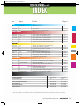
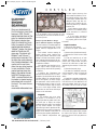
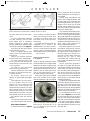
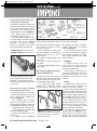
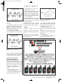
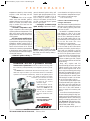
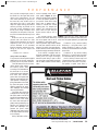
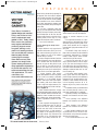
C1 Tech BULLETINS 12_Cover Temp_2006 2/16/12 7:59 AM Page c1
2012
FEBRUARY
SUPPLEMENT TO:
MAGAZINE
FORD PG
GENERAL MOTORS PG
CHRYSLER PG
IMPORT PG
PERFORMANCE PG
SHOP TIPS PG
2
6
11
16
18
23
C2 Cloyes_Layout 1 2/16/12 8:08 AM Page c2
Circle 101 on Reader Service Card for more information
1 index_Layout 1 2/16/12 7:47 AM Page 1
Year
Engine
Problem
Page #
FORD
All
3.0L Duratec
Timing Chain Service
2
2003-2004
3.8L, 3.9L and 4.2L
Balance Shaft Gear Clarification
4
1990-1993
4.0L
Oil Leak Repair
4
1999-2002
4.0L
Rattle Noise From Primary Chain Drive
5
GENERAL MOTORS
1990-2002
2.2L/134 cid
Deciphering The Differences In The Chevy 2.2L Engine
6
1988-2002
2.3L
“Quad 4” Timing Chain Installation Caution
6
1993-1994
3.1L/191 cid
Chevy 3.1L/191 Cam Bearing Bore Issues
8
2004-2005
3.6L
Noise Complaints on 3.6L Cadillac Engines
8
All
All
Close-Coupled Catalytic Converter Caution
9
All
4.6L
Cadillac 4.6L DOHC Aluminum Head, Block Cracks
9
All
All supercharged engines
GM Belt Tensioner Failure May Cause Supercharger Failure
10
CHRYSLER
1995-2006
2.4L
Chrysler 2.4L Cylinder Block Casting Identification
11
2004-2006
3.5L
Multiple Cylinder Misfire or Rough Idle
14
All
3.7L
Keeping Your Balance With 3.7L Chryslers
15
IMPORT
1988-1995
EA827
VW 16-Valve Cylinder Head Ticking Noise
16
1996
2.8L
Audi 2.8L V6 Rear Crankshaft Seal Leaks
16
1999-2001
VGS33E
Repairing Nissan Exhaust Manifold Cracks
16
2006-2007
MZR
Mazda Variable Valve Timing Noise
17
PERFORMANCE
All
All
Understanding Spark Plug Heat Range
18
All
All
Influence of Grooved Main Bearings on Performance
20
All
Carbureted engines
Holly Power Valve Myths
21
All
All
Tips For Selecting The Proper Circle Track Cam
22
All
All
Quick Test For Water in Methanol
23
All
All
Oil Pump And Engine Priming
23
All
All
Vacuum Check Engine Inspection Procedure
24
All
Small-block Chevy
Keeping Chevy 4-Bolt Mains From ‘Walking’
24
SHOP TIPS
ADVERTISER
CIRCLE NUMBERS
PAGES
AMERICAN CYLINDER HEAD
103, 109, 111, 118
3, 9, 11, 18
APEX AUTOMOBILE PARTS
113
12-13
CLOYES GEAR & PRODUCTS
101
2C
ENGINE & PERFORMANCE WAREHOUSE
108, 117, 123, 126
8, 17, 23, 4C
MAHLE CLEVITE, INC.
105, 107, 114, 122
5, 7, 14, 22
MOTOR STATE DISTRIBUTING
104, 119, 121, 124
4, 19, 21, 24
SUNNEN PRODUCTS CO.
102, 110, 120, 125
2, 10, 20, 3C
NOTE: All tech bulletins, unless otherwise noted, have been provided by Automotive Production Remanufacturers Association (APRA).
www.enginebuildermag.com | ENGINE BUILDER
1
2,4,5 Ford_Layout 1 2/16/12 7:48 AM Page 2
Timing Chain Service on
Ford 3.0L Duratec Engines
If you have to remove or replace a cylinder
head for any reason, or replace the timing
chain on a 3.0L Duratec, it can be a bit of
a challenge because Ford doesn’t provide a
Top Dead Center (TDC) timing reference
mark on the crankshaft.
You will have to use a dial indicator to
find the TDC position of the number one
cylinder on Ford’s 3.0L Duratec to make
sure the crank and camshafts are all properly aligned.
Ford says that when the crankshaft keyway is positioned at roughly the 11 o’clock
position, the number one cylinder should
be at TDC.
Before you can remove the timing
chain, the front cover has to come off the
engine.Then you have to remove the crank
sensor pulse wheel. Note the sensor wheel’s
location before you remove it.
Rotating the crank until the keyway is
Figure 1 You will have to use a dial indicator
to find the TDC position of the number one
cylinder on Ford’s 3.0L Duratec to make sure
the crank and camshafts are all properly aligned.
at the 3 o’clock position will move the
right cylinder head camshafts to the neutral
position. The timing mark on the intake
cam should be pointing to the right when
viewed from the front, and the timing mark
on the exhaust cam should be pointing
Sunnen CH-100
For fast, precision
alignment of main
bearing bores Sunnen
can’t be beat. The
CH-100 handles the
complete job of alignment and sizing of
main bearing bores in
about 30 minutes
floor-to-floor time for
an average passenger
car block and it takes just a few minutes longer for truck blocks.
With the CH-100, you will see stock removal, usually less than .003˝
(.076 mm) off the caps compared to as much as .010˝ (.254 mm) with
boring.
For more information, visit www.sunnen.com or
call 1-800-325-3670.
Circle 102 for more information
2 ENGINE BUILDER TECH SOLUTIONS GUIDE | February 2012
straight up if both cams are in the correct
position. You can now remove the chain
tensioner arm, chain guide and right timing chain.
To remove the left timing chain, rotate
the crank clockwise 600° (1-2/3rds turn)
until the keyway is again at the 11 o’clock
position.This will position the left cylinder
head cams in the neutral position. This
time, the timing mark on the intake cam
should be pointing to the left when viewed
from the front, and the mark on the
exhaust cam should be pointing straight
up. As before, you can now remove the
chain tensioner arm, chain guide and left
timing chain.
Before you can reinstall the timing
chains, you need to compress the left and
right chain tensioners in a vise. Compress
the piston until it is fully bottomed, then
temporarily lock it in place with a pin or
paper clip.
If the replacement timing chain does
not have timing marks for aligning with
the cam gears, you’ll have to mark the left
and right side chains. Start with the left
chain, and mark one link as the starting
crankshaft timing mark. Then count 29
links and make a second mark (for the
exhaust cam). Continue counting to link
number 42 and make a third mark (for the
intake cam). The second and third marks
should align with the timing marks on the
intake and exhaust cams when the chain is
slipped into place.The chain tensioner and
arm can now be installed.
Next, you do the same procedure for
the right cam. But first, you need to rotate
the crankshaft 120° clockwise so the
crankshaft keyway is at the 3 o’clock position. Mark the right timing chain and
install it the same as before.
Once both chains are in place, remove
the locking pin or paper clip from the left
and right chain tensioners.
Rotate the crankshaft 120° counterclockwise so the keyway is back at the 11
o’clock position and number one piston is
at TDC. Check to make sure all the timing marks are aligned as shown in the
illustration (Figure 1).
There should be 12 chain links
between the right and left intake and
exhaust cam sprocket marks, 27 chain
3 ACH_Layout 1 2/16/12 8:05 AM Page 3
Circle 103 on Reader Service Card for more information
2,4,5 Ford_Layout 1 2/16/12 7:48 AM Page 4
F O R D
links between the cam gears and crank on
the non-tensioned side of each chain, and
30 links between the cam gears and crank
on the tensioned side of each chain.
By Larry Carley
so that the inertial reaction to their counter-rotation cancels out in the horizontal
plane, but adds in the vertical plane. This
gives a net force equal to, but 180 degrees
out of phase with, the undesired secondorder vibration of the basic engine, thereby
2003-2004 Ford 3.8L, 3.9L and
canceling it. In a “V” configuration the
4.2L Balance Shaft Gear Clarifications
same may be accomplished by opposite
To deal with certain engine harmonics counter weights on the same/single shaft.
(particularly, inherent second-order or The ultimate result is to eliminate NVH
twice engine rpm vibration), engine (Noise Vibration Harshness).
designers often incorporate two balance
This fact is understood, and the Ford
3.8L, 3.9L and 4.2L
engines in the same family configuration have
had these shafts at various times and in different vehicles – however
recognizing changes in
the amount of teeth of
the drive and driven
gears of certain vehicles
Figure 2 Ford increased the number of teeth in the drive and
is critical.
driven gears on several Ford engine balance shafts in 2003 and
The drive and driven
2004.
gears of the balance shaft
shafts rotating in opposite directions at appear to have changed in August of 2003
twice engine speed. Equal size eccentric for vans and August of 2004 in the truck.
weights on these shafts are sized and phased The driven gear on the balance shaft
Figure 3 It’s easy to confuse the two gears, but
putting the wrong driven gear into a Ford
engine will cause real problems.
changed from 31 to 38 teeth, and as you
can see in the illustrations (Figures 2, 3) it
would not be hard to confuse the two.
The change in teeth was to further
reduce the NVH of the gears that drive the
balance shaft. Obviously a mix up would
result in a catastrophic failure. However,
what I have found is that as long as you
keep the camshaft drive gear and balance
shaft gear matched it makes no difference
which ones you use.
By Roy Berndt
Oil Leak Repair for 1990-1993
4.0L Ford V6 Engines
The 4.0L Ford V6, used in the
Aerostar, Explorer and Ranger
pickups, has been a problem
engine for oil leaks for years.
The most common oil leak
on ’90-’93 4.0L engines is often
diagnosed as a rear seal leak, but in
most cases, the problem is usually
found to be the rear of the oil pan
gasket. Since 1990, when the 4.0L
was first introduced, Ford
redesigned the gasket twice and
even the oil pan casting to eliminate the leaking issue.
The following installation
tips from Canada Engines
should help to prevent this costly and aggravating oil pan gasket
leak.
The ’90 to ’93 gasket set will
include a plastic wedge seal that
goes into a groove in the main
cap (see Figure 4).
The oil pan was redesigned in
1994 and so was the gasket
(Figure 5). The wedge seal is no
longer used because its shape is
Circle 104 for more information
4 ENGINE BUILDERS TECH SOLUTIONS GUIDE | February 2012
2,4,5 Ford_Layout 1 2/16/12 7:48 AM Page 5
F O R D
Figure 4 The oil pan gasket for the ’90 to
’93 4.0L Ford engine (top) will include a
plastic wedge seal (bottom) that goes into a
groove in the main cap
built into the gasket. Silicone is still necessary across the main cap and in the cavities
between the cap and the block.
The oil pan must be aligned with a
straight edge to the back of the block
before it is torqued down.
Source: Canada Engines LTD
Rattle Noise From Primary Chain Drive
on Ford 4.0L SOHC Engine
There have been complaints of a rattle
coming from the primary timing chain
drive area on some 1999-2002 Ford 4.0L
SOHC engines during cold engine
operation.
The 4.0L SOHC engine is one of
Ford’s Cologne V6 engines, a line of 60º,
cast iron block,V6 engines produced continuously by Ford in Cologne, Germany
since 1968. It uses a jackshaft in place of a
camshaft to drive a timing chain to each
cylinder head. The patented “Offset Ydrive” (see Figure 6) uses three timing
chains, one from the crank to the jackshaft,
one in the front of the engine to drive the
cam for the left bank and one on the back
of the engine to drive the cam for the
Figure 5 The oil pan was redesigned in 1994
and so was the gasket. The wedge seal is no
longer used because its shape is built into the gasket. Silicone is still necessary across the main cap
and in the cavities between the cap and the block.
right bank.
The noise is audible during hot and
cold engine operation (but predominantly
found on cold engines) under acceleration, typically at 2,400-2,500 rpm.To confirm presence of this noise, accelerate in
2nd gear between 2,000-3,000 rpm and
listen for a rattle noise that sounds similar
to spark knock.This may be caused by the
primary timing chain tensioner system.
Replace the primary timing chain tensioner, chain guide, jackshaft, and crankshaft sprockets with a primary timing
chain tensioner kit. The kit includes an
improved primary chain Ttensioner, as
well as updated primary chain guide, jackshaft, and crankshaft sprockets. Required
fasteners, primary timing chain, and front
cover gaskets are also included.
Use kit 2U3Z-6D256-AA (balance
shaft engines) for:
• ’99-’01 4x4 Explorer/Mountaineers;
• ’01-’02 4x4 Sport/Sport Tracs; and
• All ’02 Explorer/Mountaineers, except
engine codes 2G-960-AA and 2G-964-
Figure 6 The patented “Offset Y-drive” uses
three timing chains, one from the crank to the
jackshaft, one in the front of the engine to
drive the cam for the left bank and one on
the back of the engine to drive the cam for
the right bank.
AA.
Use kit 2U3Z-6D256-BA (non-balance shaft engines) for:
• ’99-’01 4x2 Explorer/Mountaineers;
• ’01-’02 4x2 Sport/Sport Tracs;
• ’02 Explorer/Mountaineers with
engine codes 2G-960-AA and 2G-964AA; and
• All 2001-02 Rangers. TSG
Circle 105 for more information
www.enginebuildermag.com | ENGINE BUILDER
5
6,8,9,10 General Motors_Layout 1 2/16/12 7:49 AM Page 6
Deciphering The Differences In
The Chevy 2.2L Engine
The very popular Chevrolet
2.2L/
four-cylinder engine has been a solid
steed in GM’s FWD/RWD stable. But
even after all these years, it still manages
to raise questions surrounding the Gen
presents us with the 2.2L now being
both FWD and RWD, which you would
think would mean numerous differences.
Actually, that’s not so. GM used two different head gaskets through 1997, and in
1998 went to a common head gasket for
both FWD and RWD. Using the incorrect head gasket will
result in almost immediate overheating. The
castings made changes in
those years but they followed suit in both FWD
and RWD configurations.
In 1994, the valve
stem diameter went from
Figure 1 The FWD 2.2L engine (left) requires the use of a soft 8 mm to 7 mm as well as
plug in the front of the head.The RWD model is open and must going to a roller lifter
have the bolt holes drilled and tapped.
and assembled camshaft.
The FWD version
requires the use of a
34.4 mm soft plug in
front of the head
while the RWD
model is open and
must have the bolt
holes drilled and
tapped (see Figure
1). The 1994 motor
could have casting
number 10112391 or
Figure 2 The GM 2.2L cylinder head in use since 1999 has long flat 10112391S that is the
bosses between the exhaust ports (top). The latest exhaust manifolds service replacement.
have a balance channel that runs between ports 1 - 2 and 3 - 4.
This same pattern was
followed throughout
II engine casting configurations, in par- the 1997 production cycle.
ticular the cylinder head.
In 1998, a new cylinder head (c/n
Since its birth in 1990, when the old 24575507) arrived with a heart-shaped
Chevy 2.0L engine was upgraded with a combustion chamber against a D shape.
stroke increased from 3.15˝ to 3.46˝, the The engine also had smaller 1-1/8˝
2.2L/134CID, OHV four-cylinder diameter exhaust ports vs. 1-3/8˝, and a
engine powerplant has been upgraded triangular top of the intake ports vs. a
several times: the block has been revised smaller eyebrow top. This version of the
four times and the head has been GM 2.2L engine – a single-year configchanged three times (it was discontinued uration – must have an open and drilled
after 2003, replaced by the 2.2L Ecotec). EGR port.
Let’s start in 1994 and see if we can’t
Since 1999 to present, the same
clear up some of the confusion.
cylinder head (c/n 24576146) has been
In 1994 the 2.2L Chevrolet became used. It is basically the same as c/n
the base engine in the S-series truck line, 24575507 except for crucial long flat
replacing the 2.5L Pontiac engines. This bosses that are now between the first
6 ENGINE BUILDER TECH SOLUTIONS GUIDE | February 2012
two and last two exhaust ports (see
Figure 2). The latest exhaust manifolds
have a balance channel that runs
between ports 1-2 and ports 3-4 that
must seal against the cylinder head. As
you can see, that exhaust manifold configuration assembled against the 507
head would leak.
One last quirk: the 146 head may also
be drilled for the EGR port as a service
replacement for the 507 head in 1998.
All later applications would require the
use of an EGR block-off plate (GM p/n
24575919) when used without EGR.
Special Note: 1998 applications all
required an open EGR port; 1999-2002
are closed EGR, w/exhaust manifold
port balance mounting face, (see
Illustration D and observe area that
arrows are pointing to). P/N 24576146
cylinder head may also have open EGR
port and will retro for 24575507 in
1998, or may be used 1999-2002 with
the use of EGR block off plate part
P/N24575919.
– By Roy Berndt
Timing Chain Tensioner Installation
Caution on GM 2.3L Quad 4
The timing chain tensioner on GM's
2.3L “Quad 4” engine is of the springloaded ratchet design (See Figure 3).
The tensioner assembly consists of a
housing, spring, and ratcheting plunger.
The plunger is locked into the housing
and plunger to prevent the accidental
release of the spring before or during
installation.
Once the tensioner is installed and
the chain is in place, the anti-release
device must be removed and the plunger
manually depressed into the housing to
unlock the plunger and release spring
tension on the chain.
Inadequate tension placed on the
chain will eventually result in chain
breakage and the consequential piston to
valve contact.
Failure to perform this important
final step can lead to severe engine damage.
– From MAHLE Clevite
7 Mahle_Layout 1 2/16/12 8:13 AM Page 7
Circle 107 on Reader Service Card for more information
6,8,9,10 General Motors_Layout 1 2/16/12 7:49 AM Page 8
G E N E R A L
M O T O R S
Figure 3 GM 2.3L Quad 4 Timing Chain
Tensioner Assembly. This is the late production piece, although early production is similar. Components include: A. Plunger assembly; B. Long end; C. Peg; D. Nylon Plug;
E. Spring; F. Restraint cylinder; G. J-36589
Anti-release device; H.Tensioner body.
Chevy 3.1L/191 Cam Bearing
Bore Issues
Some of the later roller cam 3.1L blocks
for the ’93-’94 Chevy VIN M are showing up with oversize cam bearing bores
that appear to have been caused by spun
cam bearings.
If a new cam bearing is installed in
a bore that has been damaged, it will
spin in the block, cut off the oil to the
cam, and cause an immediate failure
(Figure 4).
Inspect the cam bores in all of the late
3.1L castings (10137093/ 10191737/
24504089/ 24504150/ 10224227) very
carefully, paying special attention to the
#2 bore that seems to
be the most prone to
failure.
If the cam bore is
oversize, there are only
two choices:
1) You can either
knurl the O.D. of the
cam bearing to get
enough press fit, or 2)
you can junk the
block.
– By Doug Anderson
Figure 4 Some of the later roller cam 3.1L
Chevy blocks have oversize cam bearing bores
that may have been caused by spun cam bearings. Inspection will reveal if you can repair the
damage or junk the block.
Noise Complaints with 2004-2005
3.6L Cadillac Engines
If a whine, ringing or whistling noise is
reported in several 3.6L Cadillac
engines, replacement of the crankshaft
harmonic balancer is recommended if
Circle 108 for more information
8 ENGINE BUILDER TECH SOLUTIONS GUIDE | February 2012
noise is isolated to the front of engine
and balancer is three-spoke design.
Models affected include the 20042005 Cadillac CTS and SRX; and
2005 Cadillac STS with 3.6L engine
(VIN 7 - RPO LY7) and without heavy
duty cooling (RPO V03tV92).
Other complaints of a faint engine
whine-type noise have been reported at
speeds of 0-30 mph (0-48 km/h) at
1,000-2,500 rpm and may be caused by
the primary camshaft drive chain. This
type of noise may be amplified by the
vehicle's body structure.
Some installers/customers may comment on a whine, whistle, or ringing
type noise from the front of the engine
that increases in intensity as engine rpm
increases. This noise is most audible
standing in front of the vehicle with the
hood opened. If the noise fades into the
ambient engine noise by 2,000 rpm the
harmonic balancer may be the culprit.
Refer to Figure 5 and inspect the
Figure 5 Refer to the above graphic illustration and inspect the crankshaft harmonic
balancer for design type. After the inspection, if the vehicle was built with three
spoke (1) design crankshaft harmonic balancer, replace the harmonic balancer with
p/n 12597654.
6,8,9,10 General Motors_Layout 1 2/16/12 7:49 AM Page 9
G E N E R A L
Figure 6 Refer to the above graphic illustration and if the vehicle was built with the
NEW DESIGN six spoke (1) crankshaft
harmonic balancer, DO NOT replace it.
Continue on with routine diagnosis to isolate the noise.
crankshaft harmonic balancer to determine the design type. If the vehicle was
built with a three-spoke design crankshaft harmonic balancer, replace the harmonic balancer with a new unit (P/N
12597654.)
However, if the vehicle is equipped
with the V03N92 Heavy Duty Cooling
package, DO NOT replace the six-spoke
design crankshaft harmonic balancer (see
Figure 6). Continue with routine diagnosis to isolate the noise.
Close-Coupled Converter Caution
On Late Model GM Vehicles
Certain late model General Motors
vehicles may be equipped with a new
style of catalytic converter, technically
known as the close-coupled catalytic
converter (see Figure 7).
This new-style converter provides
quick catalyst warm-up, resulting in
lower tailpipe emissions earlier in the
operating cycle. If an engine failure
occurs (such as a broken intake/exhaust
valve or piston), debris may be deposited
in the converter through the engine
exhaust ports.
If the engine failure is due to a severe
overheating event, damage to the ceramic “brick” inside of the catalytic converter may occur. This could then result in
ceramic debris being drawn into the
engine through the cylinder head
M O T O R S
exhaust ports.
If a replacement engine is installed
due to either of these instances, the
replacement engine may ultimately fail
due to the debris being drawn into the
combustion chamber upon startup.
Remind your installers that when
they replace an engine due to a failure of
this type, they must inspect the converters and ALL transferred components
such as the intake and exhaust manifolds.
Remove any debris that is found.
In cases where engine failures
occurred as a result of severe overheating, installers should inspect each catalytic converter for signs of melting or
cracking of the ceramic “brick.” If damage is observed, the converter should be
replaced.
Cadillac 4.6L DOHC Aluminum Cylinder
Head and Block Crack Cautions
Cadillac 4.6L DOHC engines may be
prone to cracking of the aluminum
block casting around the cast iron liner
Figure 7 Certain late model General Motors
vehicles may be equipped with a new style of
catalytic converter, technically known as the
close-coupled catalytic converter. Engine failures can damage the converters which, if not
inspected properly, can then cause subsequent
damage to a replacement engine.
(Figure 8). Knowing that this possibility exists, make a close examination of
the deck prior to doing any machining
at all – and before you then spend
der
n
i
l
y
C
Why from
Heads an
a
c
i
r
e
m
A
?
QUALITY
Look to American Cylinder Head for quality built on a heritage of nearly a half-century of experience. Continual
improvement in our processes have allowed us to achieve
ISO compliance as well as receiving the coveted TS16949
OE certification, assuring you of the most reliable and precisely-remanufactured cylinder heads in the industry.
Our Quality is complemented by our Service and
commitment to The Future in providing the finest in
remanufactured cylinder heads.
Buy American!
For information e-mail [email protected]
Circle 109 for more information
www.enginebuildermag.com | ENGINE BUILDER
9
6,8,9,10 General Motors_Layout 1 2/16/12 7:49 AM Page 10
G E N E R A L
M O T O R S
Figure 8 The aluminum 4.6L Cadillac block may crack
outside the cast iron cylinder liner and is extremely hard to
detect.The above crack became visible only after the deck face
was machined.
numerous hours on cylinder head bolt repairs.
The second tip involves cylinder head c/n 3533989
and 12554607, which would be the left head (or front, in
the transverse mount engine) that has an alternator bracket bolted onto it in some applications. This head will
always have the bosses for this mounting bracket but both
of them may or may not be drilled (see Figure 9).
Figure 9 The cylinder head on the top has the bolt holes drilled and tapped
If you want to avoid problems I recommend that you
for the alternator bracket when used. The head below does not but both have drill all of the bosses, thereby eliminating the possibility
the same casting number. To avoid potential warranty issues drill and tap all
of having a warranty problem upon installation and also
heads.
reducing head proliferation.
– By Roy Berndt
Sunnen LBB-1660 Manual Hone
For precision rod reconditioning and pin fitting, the
Sunnen LBB-1660 manual hone can turn old rods
into like-new rods. For added flexibility, the
LBB-1660 also handles King Pins, air
compressors and small bore engines.
The LBB produces a round and
straight honed bore, equal to or
better than manufacturers’
new rods, and it helps keep
your rod inventory to a minimum by enabling you to give
over-the-counter service on
customers’ own rods.
For more information,
visit www.sunnen.com or
call 1-800-325-3670.
Circle 110 for more information
10 ENGINE BUILDER TECH SOLUTIONS GUIDE | February 2012
GM Belt Tensioner Failure May
Cause Supercharger Failure
All GM vehicles equipped with superchargers may be prone to premature failure of supercharger bearings.
When the belt tensioner starts to fail,
belt tension increases as side-loading in
the supercharger rear bearing.
Periodic inspection of the belt tensioner should be part of the regular maintenance routine. Before operating the
replacement supercharger, the tensioner
must be inspected and replaced if defective. Unless the tensioner is checked and
replaced as needed, supercharger-bearing
failure will occur, causing premature catastrophic failure.
While this problem is prevalent on
GM vehicles, this inspection should be
performed on all belt-driven supercharged vehicles. Please check the service
manual for the recommended inspection
and service.
Note: This bulletin is supplied as technical information only and is not an
authorization for repair.
– By CARDONE Industries TSG
11,14,15 Chrysler_Layout 1 2/16/12 7:50 AM Page 11
on the passenger side to the back of the pan rail on the passenger side of the
block on the driver’s side in order to FWD blocks.
accommodate the new, bolt-on “target
These blocks have “RWD” cast on
Chrysler replaced its old SOHC four ring” for the crank sensor.
the passenger side so they’re easy to spot.
cylinders with an all-new family of
There were some other changes The Catch-22 is that this block was used
SOHC and DOHC engines in 1995. made to accommodate the turbo motor, for both the Wrangler and Liberty in
too, including a boss on the pas- ’03, but only for the Wrangler in ’04
senger side that can be drilled because the Wrangler platform continfor the oil return from the turbo ued to use the old style computer and
and an additional oil galley crankshaft (without “NGC”) through
inside the block that’s machined ’04 even though the Liberty got the
for the four “oil squirters” that “NGC” computer along with a new
are used to help cool the pistons block and crank in ’04.
2004-2005 RWD: The RWD block
on the turbo motors. Look for a
was revised in 2004 to accommodate the
4781632AA/AB casting.
2003-2004 RWD: Chrysler bolt-on “target ring” with more notches
installed the 2.4L motor in both that was used with the new “NGC” comthe RWD Jeep Wrangler and puter so the hole for the sensor was
Liberty beginning in 2003. The moved over to the driver’s side and back
Figure 1 The hole for the oil sender on the passenger RWD block is a unique casting toward the bell housing, just like it was on
side of the 2.4L was moved back about 6˝ in 2001 so (53010502AA) that doesn’t have all the ’03 cars. The revised 53010502AB
it’s much closer to the bell housing.
the “ear” that sticks out from the casting was used for the Liberty in ’04 and
front of the block down by the ’05 and the Wrangler in ’05 and ’06.
There were 2.0L SOHC and DOHC
versions, along with a 2.4L DOHC that
was installed in the FWD cars and minivans. Over the years, this engine has
been used in several other applications
including the PT Cruiser, the RWD
Liberty and Wrangler, and the SRT4
Neon. It has evolved over the years, too,
so there are seven short blocks that use
six block castings. So, let’s take a look
and see if we can make some sense out
of all the changes to the blocks.
1995-2000: The original casting was
a 4621443 block that had a 4621445
bedplate. It was used up through 2000.
Count on American Cylinder Head to deliver standard-setting service at
2001: The hole for the oil pressure
every step. From the moment you explore our electronic or hard-copy
sender on the passenger side was moved
catalog you’ll find user-friendly data and comprehensive coverage for the
back about 6˝ in 2001 so it was much
full range of vehicles you service, including domestic and import models,
closer to the bell housing. It’s a
as well as marine, H-D, ag, and industrial applications. Once you order,
4621443AB casting.
our three warehouses will ship your order promptly since we stock 96%
2002: The oil drainback hole in the
of our part numbers. And we support you after the sale with technical
head was enlarged in ’02 so there was
and product information and warranty coverage that can’t be beat.
another “bulge” added to the block on
the driver’s side, between the third and
Our Service is complemented by our Quality and commitment to
fourth cylinders. It’s an all new casting
The Future in providing the finest in remanufactured cylinder heads.
that has 4781655AA on the driver’s side.
2003-2006: There was another all
Buy American!
new FWD block in ’03 that incorporated several more changes, but the most
For information e-mail [email protected]
noticeable one was the change in the
location of the hole for the crank sensor;
it was moved from the front of the block
1995-2005 Chrysler 2.4L
Cylinder Block Casting Identification
r
e
d
n
i
l
y
Why C from
Heads can
Ameri c
?
Service
Circle 111 for more information
www.enginebuildermag.com | ENGINE BUILDER
11
12-13 Apex_Layout 1 2/16/12 8:06 AM Page 12
12-13 Apex_Layout 1 2/16/12 8:06 AM Page 13
Circle 113 on Reader Service Card for more information
11,14,15 Chrysler_Layout 1 2/16/12 7:50 AM Page 14
C H R Y S L E R
increase engine warm-up time
and increase the likelihood of carbon deposit buildup on the stem
of the engine exhaust valve. Fuel
detergent quality may also contribute to the condition; the customer may want to try a different
brand of fuel.
2.Verify that the engine misfire
condition is not caused by faulty
Figure 2 The oil drainback hole in the head on the engine mechanical or electrical
2.4L was enlarged in 2002, so the block had a pro- components.
nounced bulge on the driver’s side between the third
3. If the engine mechanical
and fourth cylinders.
and electrical systems are operating properly, perform the Repair
Multiple Cylinder Misfire or Rough
Procedure.
Idle on 2004-'06 Chrysler 3.5L Engines
This information for installers applies to
Chrysler models built after Feb. 1, 2004
(MDH 0201XX) equipped with a 3.5L
engine.
This bulletin involves rotating all
engine exhaust valves, replacing the
valve spring retainer locks with a new
design to increase valve rotation at lower
rpm, inspecting/replacing the MAP sensor (as necessary) and decarbonizing the
combustion chamber.
The customer may experience occasional engine misfire (rough-running
engine) during certain vehicle operating
conditions.
In addition, MIL illumination may
also have occurred due to DTC P0300 Multiple Cylinder Misfire.Various single
cylinder misfire DTCs may also be present. If the frequency of misfire is high,
the powertrain control module (PCM)
may place the engine in “limp-in” mode.
The misfire condition may be caused
by one or more engine exhaust valves
that are slow to close due to a buildup of
carbon on the valve stem.
Diagnosis
1. This condition may occur when
the engine is not allowed to run at
engine rpms that are greater than 3,500.
At 5,000 rpm or higher, the engine
exhaust valves will rotate if not impeded
by high carbon deposits. Low engine
rpms and high carbon deposits are associated with short-trip driving where the
engine is not allowed to fully warm to
normal engine operating temperatures.
Cold ambient temperatures will
Circle 114 for more information
14 ENGINE BUILDER TECH SOLUTIONS GUIDE | February 2012
Repair Procedure
1) Relieve the fuel pressure.
2) Remove the upper intake manifold.
3) Remove the cylinder head cover(s).
4) Remove the rocker arm and shaft
assembly.
5) Clean and mark the tip of each
exhaust valve stem at the 12 o’clock
position with a paint marker. The paint
mark will be used later to assist with
determining the amount of valve rotation.
6) Remove the spark plugs.
7) Rotate the crankshaft clockwise,
until the number 1 piston is at Top Dead
Center (TDC) on the compression
stroke.
8) Install the compression tester spark
plug adapter in cylinder #1 spark plug
hole. With the air hose attached to the
spark plug adapter, apply 90 to 100 psi
air pressure. This is to hold the valves
Figure 3 Using a valve spring compressor tool
with the valve spring adapter, slightly compress
the exhaust valve spring to release tension
against the valve and valve spring retainer on
3.5L engines.
11,14,15 Chrysler_Layout 1 2/16/12 7:50 AM Page 15
C H R Y S L E R
Figure 4 Inspect the MAP sensor for LX models (left) or for CS models (right). If the MAP
sensor is the new style, no further action is necessary for the MAP sensor.
into place while servicing the components.
9) Using a valve spring compressor
tool (MD 998772A) with the valve
spring adapter (6527 or equivalent),
slightly compress the exhaust valve
spring to release tension against the valve
and valve spring retainer (see Figure 3).
10) Remove the valve spring retainer
locks and discard the locks.
Note: It is important that the valve
rotation section of this repair procedure
be performed.
Caution: Only grab the valve stem
tip, being careful not to cause damage.
11) Using needle-nose pliers, grab
the tip of the valve stem and rotate the
exhaust valve 90° (move the mark to the
3 o’clock position).
12) Install two new valve spring
retainer locks (p/n 53022277AA).
13) After installing the locks, release
the tension on the valve spring and verify proper installation.
14) Remove Special Tool MD
998772A (1) and the spark plug adapter
tool.
15) Repeat steps 7-14 on the remaining five cylinders using the firing
sequence 1-2-3-4-5-6. Make sure the
piston is at TDC in each cylinder of the
exhaust valve spring retainer lock that is
being removed. When all the exhaust
valves have been rotated 90° and all the
exhaust valve spring retainer locks have
been replaced, proceed to the next step.
16) Install the rocker arm and shaft
assembly.
17) Install the cylinder head cover(s).
18) Install the upper intake manifold
MAP Sensor Inspection
1) Inspect the MAP sensor – Figure 4
for LX models or CS models. If the MAP
sensor is the new style, no further action
is necessary for the MAP sensor. If the
MAP sensor is the old style, proceed to
the next step.
2) Replace the MAP sensor with p/n
05033310AC for LX models or p/n
04896003AB for CS models. If the vehicle is a CS model, be sure the new sensor
opening is facing a downward direction
when installed and only use one fastener.
–From ALLDATA
Keeping Your Balance With
3.7L Chryslers
While an optimally balanced V6 engine
would have either 60 or 120 degree angles
between the two banks of cylinders, many
current V6 engines are derived from 90
degree angle V8 engines. While this configuration gives an evenly spaced firing
order in an 8-cylinder engine, a 6-cylinder engine develops a loping rhythm.
During each rotation of the crankshaft
three of the cylinders fire at 90-degree
intervals, followed by a gap of 90 degrees
Figure 5 The circle shows where the roll pin
(arrow) and spline gear should be aligned for
proper timing of the balance shaft on the
3.7L. This assembly has spun on the center
shaft over 90 degrees.
with no power pulse. Much of this issue
was eliminated by the use of the split journal crankshaft.
Recently many manufacturers have
found it wise to adapt the balance shaft
concept as well, using a single shaft with
counterweights spaced so as to provide a
vibration which cancels out the shake
inherent in the 90 degree V6. If you buy a
new vehicle today, you most likely have an
engine with a balance shaft.
One of those V6 engines that incorporate the single balance shaft technology is
the 3.7L Chrysler engine that utilizes the
split journal crankshaft.The single balance
shaft goes down the center of the block in
an area that you may have thought the
camshaft would reside. Since the 3.7L is a
SOHC engine it was a perfect spot to
drop the single balance shaft unit.
What would happen if you put a balance shaft into the engine out of time? It
would just exacerbate the problem and
the result would be a shaker instead of a
smoothie. Imagine if you did time it correctly but you were actually duped into
thinking that you were in time?
Unfortunately, that is exactly what happens if certain components don’t live up
to expectations.
The 3.7L engine has a gear cluster in
the center of the engine that drives not
only the balance shaft but the two timing
chains as well. And many say it is a brave
man who takes on timing these engines –
there are four chains: one “Morse” type
chain for timing to the crank; two sprocket type chains for the two camshafts; and a
spline type gear for the balance shaft all
installed simultaneously.
The spline gear drives that balance shaft
and the two sprocket gears drive the timing chains. On the spline gear side of the
gear cluster there is a roll pin that locates
the index of the gear. Numerous examples
have been cited where the spline gear has
“shifted” and the roll pin sheared.
It is not always easy to see but if you
look closely at Figure 5 you will see that
the roll pin has been sliced in half and is
now out of time and will cause a vibration
rather than a counter measure to vibration.
Be aware of this situation because it
can be easily missed, especially when the
gear cluster appears to be perfect in every
other way. TSG
www.enginebuildermag.com | ENGINE BUILDER
15
16-17 Import_Layout 1 2/16/12 7:51 AM Page 16
Diagnosing VW 16V Cylinder Head
Ticking Noise at 2,000 RPM
Dimensional differences between the
camshaft sprockets and the cam timing
chain create a rattling noise that can
be heard from the cylinder head at
approximately 2,000 rpm (Figure 1).
This bulletin refers to all MY
Volkswagen 16-valve engines.
As of 11/88, starting with VIN 067
722 a manufacturing tolerance change
has been made to the camshaft
sprockets. If a customer complains
because of persistent noise, replace
both camshafts with the following:
Intake cam p/n: 027 109 021 AJ
Exhaust cam p/n: 027 109 022 F
Figure 3 A ticking noise may be heard from a cracked exhaust manifold on certain Nissan engines.
Typically, inspection for cracks between the #1 and #3 ports should be conducted.
tool that comes with seal and apply a
small amount of engine oil to the
inner lip of the seal.
Note: Lubricating the seal lip will
ease seal installation and reduce the
tendency of the seal to roll as it is
being installed.
2) Carefully reinstall the seal installation tool.
3) Install oil seal and flange with
new gasket.
4) Torque reusable flange bolts to 7
ft.lbs. (10Nm).
1999-2001 Exhaust Manifolds Cracked
in Nissan VGS33E Engines
Figure 1 Dimensional differences between
the camshaft sprockets and the cam timing
chain may create a rattling noise on some
Volkswagen 16-valve engines that can be
heard from the cylinder head at approximately 2,000 rpm.
1996 Audi 2.8L V6 Rear Crankshaft
Seal Leaks After Replacement
Oil may leak from the rear crankshaft
seal after seal replacement due to the
seal lip rolling while installing the
new seal (Figure 2).
This condition affects 1996 A4
with 2.8L V6 (engine code AFC).
When replacing the seal, the new seal
is supplied pre-installed in the flange.
• Seal/Flange P/N: 078 103 171H;
• Flange gasket p/n: 078 103 181
(must be ordered separately).
Caution: Part numbers are for reference only.
1) Carefully remove installation
A ticking or exhaust noise has been
reported coming from the right-hand
exhaust manifold area of some 19992001 Nissan VGS33E engines.
If a cracked right-hand exhaust
manifold on a 1999-2001 Nissan
VGS33E engine is discovered when
Figure 2 When replacing the oil seal on
1996 Audi A4 models with V6 engines,
make sure the new seal is supplied preinstalled in the flange.
16 ENGINE BUILDER TECH SOLUTIONS GUIDE | February 2012
the exhaust heat shield is removed,
installers must replace the exhaust
manifold (Figure 3).
If one of these symptoms should
occur, use the following to diagnose
the condition, replacing the righthand exhaust manifold and related
parts as described.
Diagnosis
1) Installers should verify the
source of the noise with the engine
running that it is coming from the
right-hand manifold area.
2) If the noise is coming from the
right-hand manifold area, remove the
heat shield and inspect for cracks
between the #1 and #3 ports on the
manifold.
Repair
1) Separate the catalyst from the
right-hand exhaust manifold and
remove it to allow for clearance.
Caution: The nuts that attach the
catalyst to the exhaust manifold have a
self-locking design and require some
effort to remove. Apply penetrating oil
to the threads and allow it to soak in
before attempting to remove the nuts.
Use a tight-fitting six-point socket
to avoid rounding off the corners of
the nuts during removal. If any of the
nuts or studs are damaged during
removal, replace them as needed.
2) Remove the exhaust manifold
from the head (See Figure 4 for loosening sequence of manifold nuts).
NOTE: If any of the nuts or studs are
damaged during removal, replace them
16-17 Import_Layout 1 2/16/12 7:51 AM Page 17
I M P O R T
• 2007 Mazda CX-7 vehicles produced before April 1, 2007.
When the engine is first started,
some vehicles may exhibit a loud ticking noise from the variable valve timing (VVT). This is caused by the lock
pin of the variable valve timing actuator not fully engaging.
Heat treatment has now been
added around the hole of the variable
Figure 4 Sequence for loosening the exhaust valve timing rotor lock pin to prevent
this from happening.
manifold nuts on the Nissan VGS33E.
Customers having this concern
as needed.
should have their vehicle repaired
3) Install the replacement manifold using the following repair procedure.
with a new gasket onto the head. See
Figure 5 for tightening sequence of
Repair
manifold nuts. See Figure 3 for mani1) Verify variable valve timing
fold nut torque specifications.
noise.
4) Re-attach the catalyst to the
2) After the engine cools down,
exhaust manifold. NOTE: Ensure that replace the variable valve timing actuator.
NOTE: Do not use the printed
service manual as the procedure has
been updated online.
Figure 6 Location of the variable valve actuator
for the Mazda MZR engine.
3) Change the engine oil (5W-30)
only, then start and let the engine idle
for 5 minutes. This is to remove contaminants from the engine.
4) Make sure there is no fuel leakage around the high pressure fuel
pump.
5) After the engine cools down,
change the engine oil (5W-30) again,
and the filter.
6) Verify repair.
NOTE: This repair calls for the oil
to be changed two times. TSG
Figure 5 Sequence for tightening the exhaust
manifold nuts on the Nissan VGS33E.
all bolts securing the manifold and heat
shields are installed and are torqued to
the specifications shown in Figure 3.
Variable Valve Timing Noise
Complaints When Starting
2006-2007 Mazda MZR Engines
Customers may complain of a loud
ticking noise from the variable valve
timing (VVT). This is caused by the
lock pin of the variable valve timing
actuator not fully engaging.
Affected models with MZR
engine:
• 2007 Mazdaspeed3 vehicles produced before April 1, 2007;
• 2006-2007 Mazdaspeed6 vehicles
produced before April 1, 2007;
Circle 117 for more information
www.enginebuildermag.com | ENGINE BUILDER
17
18-22 Performance_Layout 1 2/16/12 7:53 AM Page 18
Understanding Spark Plug Heat Range
Finding the right spark plugs for a modified engine is a little more involved than
just looking in a catalog for make and
model.
Depending on the engine modifications you’ve made, you’ll need to take a
few extra factors into consideration
before settling on the right spark plugs
(Figure 1). These factors include spark
plug seat design, thread length and diameter, and reach. One of the most important – and least understood – factors in
choosing aftermarket spark plugs is the
heat range.
Heat range is the speed at which a
spark plug can transfer heat from the firing tip to the cylinder head water jacket
and into the cooling system. Choosing
the right heat range is crucial for high
performance engines. If the heat range is
too cold, the spark plug will be unable to
Figure 1 As a rule of thumb, you can expect
to require one heat range colder than the factory-supplied plugs for every 75-100 horsepower you’ve add with your modifications.
properly self-clean by burning off carbon deposits.
If it the heat range is too hot, your
r
e
d
n
i
l
y
Why C from
Heads can
Ameri c
?
The Future
Trust American Cylinder Head to constantly look to The Future by utilizing cutting-edge parts, equipment, and technology to provide you the
most precisely-engineered and durable cylinder heads in the industry.
We invest heavily in equipment and training so we continue to meet the
exacting standards of ISO compliance and OE Quality Certifications, a
level of excellence rarely achieved in the industry. We're here for you
today, we'll be here for you tomorrow, and beyond.
Our commitment to The Future is complemented by our Quality and
Service in providing the finest in remanufactured cylinder heads.
Buy American!
For information e-mail [email protected]
Circle 118 for more information
18 ENGINE BUILDER TECH SOLUTIONS GUIDE | February 2012
engine could experience detonation,
pre-ignition, or power loss. Most spark
plug manufacturers recommend that the
tip temperature remain between 900° F
(500° C) and 1,500° F (850° C).
Heat ranges are designated by each
spark plug manufacturer with a number.
In broad terms, spark plugs are often
referred to as “hot plugs” or “cold
plugs.” A cold plug has a shorter insulator nose length – the distance from tip
to spark plug shell – and transfers heat
rapidly from its firing tip to the cylinder
head water jacket.
Cold plugs are ideal for high rpm
engines, forced induction applications,
and other instances where the engine
produces high operating temperatures.
Conversely, hot plugs are good for applications that operate mainly at low rpms.
Because they have a longer insulator
nose length, heat is transferred from the
firing tip to the cooling system at slower pace. This keeps the spark plug temperature high, which allows the plug to
self clean and prevent fouling.
Unfortunately, heat range numbers
are not universal – each brand has its
own method for assigning heat ranges.
You’ll need to talk with your sales rep or
consult with the manufacturer to find
the best heat range for your application
and spark plug brand. Be prepared to
supply some basic vehicle information,
including any modifications you’ve
made.
As a rule of thumb, you can expect to
require one heat range colder than the
factory-supplied plugs for every 75-100
horsepower you’ve added with your
modifications, according to Champion
Spark Plugs. Here are some more basic
guidelines to get you pointed in the
right direction:
• Supercharging/turbocharging:
For-ced induction leads to increased
cylinder pressure and temperature,
which could lead to detonation.
Depending on the exact application,
you’ll need to go with a significantly
colder heat range (faster heat transfer)
over stock.
• Nitrous oxide: The high cylinder
19 Motorstate_Layout 1 2/16/12 8:08 AM Page 19
Circle 119 on Reader Service Card for more information
18-22 Performance_Layout 1 2/16/12 7:53 AM Page 20
P E R F O R M A N C E
temperatures caused by nitrous usually
requires a colder heat range over the
stock plug.
• Methanol: Since it has a higher
octane level than standard gasoline,
methanol delivers more complete combustion. As a result, you’ll need a colder
plug to transfer more heat from the
combustion chamber.
• Increased compression ratio:
Higher compression ratios mean higher
cylinder pressure and temperature. Once
again, you’ll need a colder heat range to
rapidly transfer all that extra heat to the
cooling system.
• Air/fuel mixture modifications:
Lean air/fuel mixtures raise the operating temperature, along with the plug tip
temperature, possibly causing knock or
pre-ignition. Use a colder heat range for
leaner air/fuel mixtures. Rich air/fuel
mixtures can cause the plug temperature
to dip, allowing carbon deposits to build
up on the tip. Use a hotter heat range for
rich air/fuel mixtures.
• Advanced ignition timing: In
general, advanced ignition timing will
raise the spark plug temperature. In fact,
NGK estimates an increase of 70° to
100° for every 10° advance in ignition
timing. For this reason, you may need to
go with a colder heat range to prevent
knock or pre-ignition.
• Prolonged acceleration/high
speed driving: Frequent and drawn-
Figure 2 As engine and bearing technology
developed, the bearing grooving was removed
from modern lower main bearings creating a
thicker oil film.
Sunnen SV-10 Cylinder Hone
Sunnen’s SV-10 Cylinder Hone combines the latest technology with
the consistency and dependability of the legendary Sunnen Cylinder
King.
The SV-10 comes standard with two time and money savers – auto
dwell and rough and finish cycle. Auto dwell allows for unattended
operation. The machine automatically dwells in the tightest part of
the bore – top, middle or bottom. The rough
and finish cycle removes stock fast
and automatically switches
to finish for the correct
crosshatch angle.
With two motors, one for
the spindle and one for the
stroker, the SV-10 has the
capability to run standard
tools as well as Sunnen’s
DH-series diamond hone
head.
For more information,
visit www.sunnen.com or
call 1-800-325-3670.
Circle 120 for more information
20 ENGINE BUILDER TECH SOLUTIONS GUIDE | February 2012
out acceleration and high-rpm driving
raises combustion temperatures and generally requires a colder heat range.
– From Summit Racing
Influence of Grooved Main Bearings
on Engine Performance
Manufacturers are frequently asked what
difference grooving makes.Various forms
of main bearing grooving have been
used over the years.
It’s essential to understand that bearings depend on a film of oil to keep
them separated from the shaft surface.
This oil film is developed by shaft rotation. As the shaft rotates it pulls oil into
the loaded area of the bearing and rides
up on this film much like a tire
hydroplaning on wet pavement.
Grooving in a bearing acts like tread
in a tire to break up the oil film. While
you want your tires to grip the road, you
don’t want your bearings to grip the
shaft, so grooving is bad for maintaining
an oil film. The primary reason for having any grooving in a main bearing is to
provide oil to the connecting rods.
Without rod bearings to feed, a simple
oil hole would be sufficient to lubricate
a main bearing.
Many early engines used full
grooved bearings and some even used
multiple grooves. Those choices were
based on what engineers knew at the
time. As engine and bearing technology
developed, the negative effect of grooving was recognized and bearing grooving was removed from modern lower
main bearings. The result is in a thicker
film of oil for the shaft to ride on.
This provides a greater safety margin
and improved bearing life. Upper main
shells, which see lower loads than the
lowers, and hence don’t apply the same
load to the oil film, have retained a
groove to supply the connecting rods
with oil.
In an effort to develop the best possible main bearing designs for high performance engines, manufacturers have
investigated the effects of main bearing
grooving on bearing performance. The
graph (Figure 2) illustrates that a simple 180° groove in the upper main shell
is still the best overall design.
While a slightly shorter groove of
18-22 Performance_Layout 1 2/16/12 7:53 AM Page 21
P E R F O R M A N C E
140° provides a marginal gain, most of
the benefit is to the upper shell, which
doesn’t need improvement. On the
other hand, extending the groove into
the lower half, even as little as 20° at
each parting line (220° in total), takes
away from upper bearing performance
without providing any benefit to the
lower half. It’s also interesting to note
that as groove length increases so does
horsepower loss and peak oil film pressure, which is transmitted directly to the
bearing.
Notes: You will still find some fullgrooved main sets offered for older
engines where demand is low and the
engineering cost to bring the sets to
current standards is not warranted
(bearings generally represent the technology of the time the engine was
developed).
– From MAHLE Clevite Inc.
Holley Power Valve Myths
The power enrichment system supplies
additional fuel to the main system during heavy load or full power situations.
There still seems to be a lot of misconception about Holley carburetors blowing power valves.
According to the manufacturer,
this should be of no concern.
Holley performance carburetors
since 1992 have utilized a
power valve check system that
effectively eliminated this infrequent problem. Consisting of a
spring, brass seat and check ball,
the check ball system is 100%
effective protecting the power
valve diaphragm from damage
due to engine backfire.
The power valve check ball
is designed to be normally open
but quickly seals to close off the
internal vacuum passage when a
backfire occurs. Once closed,
the check valve interrupts the
pressure wave generated by the
backfire, thus protecting the
power valve diaphragm. This
prevents the power valve’s
diaphragm from rupturing due
to an engine backfire, according
to the company.
Holley carburetors utilize a
vacuum operated power enrichment system (Figure 3) and a
selection of power valves is available
to “time” this system’s operation to
your specific needs. Each Holley
power valve is stamped with a
number to indicate the vacuum
opening point. For example, the
number “65” indicates that the
power valve will open when the
engine vacuum drops to 6.5˝ or
below.
An accurate vacuum gauge Figure 3 Holley carbs use a vacuum operated power
should be used when determining enrichment system and a selection of power valves is availthe correct power valve to use. A able to “time” this system’s operation to your specific needs.
competition or race engine which
has a long duration high overlap camshaft
EXAMPLE: 13˝ Hg vacuum reading
will have low manifold vacuum at idle divided by 2 = 6.5 power valve. If your
speeds. If the vehicle has a manual trans- reading divided by 2 lands on an even
mission, take the vacuum reading with the number you should select the next lowest
engine thoroughly warmed up and at idle. power valve.
EXAMPLE: 8˝ Hg vacuum reading
If the vehicle is equipped with an
automatic transmission, take the vacuum divided by 2 = 4 power valve. Since there
reading with the engine thoroughly is no #4 power valve you should use a 3.5.
Most of Holley’s “Street Legal” and
warmed up and idling in gear. In either
case, the power valve selected should be “Street Performance” carburetors incorhalf the intake manifold vacuum reading porate a power valve blow-out protection system. A special check valve is
taken.
Circle 121 for more information
www.enginebuildermag.com | ENGINE BUILDER
21
18-22 Performance_Layout 1 2/16/12 7:53 AM Page 22
P E R F O R M A N C E
located in the throttle body expressly for
this purpose. This check valve is designed
to be normally open but will quickly seat
to close off the internal vacuum passage
when a backfire occurs. Once closed, the
check valve interrupts the pressure wave
caused by the backfire, thus protecting the
power valve.
If you have a carburetor older than
1992 (or you have experienced an extreme
backfire) and expect a blown power valve,
use this simple test. At idle turn the idle
mixture screws (found on the side of the
metering block) all the way in. If the
engine dies the power valve is not blown.
– From Holley Performance
Tips For Selecting The Proper Circle
Track Cam
An engine builder is only as good as his
customer’s information, and if your circle
track customer doesn’t give you the necessary answers, he may not be pleased
with the cam you choose.
This isn’t always the builder’s fault, but
is often followed by the racer selling the
cam to another racer who thinks it’s the
best cam he ever ran. Why did this cam
work so well for one racer and not for
another? The reasons can be many. The
following are some tips for selecting the
proper cam for circle track applications.
• Longer duration cams require
tighter lobe separation to have any power
off the corner (not usually a preferable
combination in 2 bbl classes). Shorter
duration cams with wider lobe separations usually yield much flatter torque
curves. Longer rod engines seem to prefer shorter durations and wider lobe separation (Figure 4).
• Stock exhaust manifolds or a highly
restricted exhausts usually respond well to
shorter exhaust duration and wider lobe
separation. Power increases are most evident at higher rpm where exhaust backpressure is greatest and reversion is most
prevalent.
• Most unported heads approach 85
or 95 % of peak flow at .400˝ to .450˝ lift
and do not need or want a maximum
valve lift over .540˝ to.555˝. Often a low
cam lift with 1.65 or 1.7 ratio rockers is
very helpful on the intake side as long as
lift is kept to about .550˝. Exhaust is less
critical with 1.5 or 1.55 being the most
popular. Dyno testing doesn’t test driCircle 122 for more information
22 ENGINE BUILDER TECH SOLUTIONS GUIDE | February 2012
Figure 4 Longer rod engines seem to prefer
shorter durations and wider lobe separation.
vability or throttle response of the
engine.
• The important numbers on a dyno
sheet are about a thousand RPM above
and below peak torque and peak horsepower. Peak numbers are for bragging
purposes and high peak numbers do not
win races.
• The benefit of high ratio rockers is
faster valve movement and the added lift
is frequently detrimental in unported
heads. It often helps to utilize a lower
cam lift with high ratio rockers.
• Changing the valve lash is a good
way to get an indication of which way to
go for your next cam change. You won’t
hurt anything by going too tight but too
loose will let the valves slam shut causing
damage to valves and seats. .004˝ to .006˝
loose is usually OK.
• Look at the “major intensity” numbers to get an idea as to how radical the
profile is (major intensity is the difference
between the .020˝ duration and the .050˝
duration). Lower numbers are more radical but anything less than 26 or 27
degrees may be very hard on the valve
train.
• Camshaft Intensity is a measurement
term coined by Harvey Crane to compare ramp characteristics of camshafts.
- Hydraulic Intensity is the difference
between .004˝ duration and .050˝ duration.
- Minor Intensity is the difference
between .010˝ duration and .050˝ duration.
- Major Intensity is the difference
between .020˝ duration and .050˝ duration.
• Lower numbers indicate more radical profiles, but too low can be too radical and lead to noisy valve train operation
and even to broken parts.
– From Camcraft Performance Cams TSG
23-24 Shop Solutions_Layout 1 2/16/12 7:54 AM Page 23
Quick Test For Water in Methanol
Most engine builders know that
methanol absorbs water from the day
you break the seal. But racers don’t usually carry a specific gravity gauge to the
track. Here’s what you may wish to tell
your customers. Once the motor is up to
full temperature with the ignition off,
remove the air cleaner and open the
throttle all the way, holding it open for
about 30-45 seconds. With the throttle
open, take a light and look through the
carburetor to the floor of the manifold.
With the motor being “hot” the
methanol evaporates quickly and if you
have water in the fuel you will see drops
of water sitting at the bottom of the
manifold. This is a quick way to tell how
good your methanol is.
Mark Those Guides
When installing more than one valve
guide in an OHC cylinder head, it’s
often difficult to see well enough to get
the depth correct every time, so I just lay
up. Proper priming will help assure a
trouble-free rebuild. There are two preferred methods to prime oil pumps and
newly rebuilt engines. The first method
listed covers oil pumps driven by the
camshaft and the second covers those
driven by the crankshaft.
Priming camshaft driven oil pumps:
These pumps are typically referred to as
wet sump pumps since they sit low in
the engine oil pan and are partially submerged in the engine oil. To prime, first
submerge the inlet of the oil pump in
clean oil and rotate the drive shaft in the
correct direction. If it does not pump,
change direction of shaft rotation until
oil flows from the pump outlet. Drain
excess oil from the pump and install it
on the engine.
Fill the oil filter and install it; then fill
the engine with oil. Install the correct
priming tool, which can be a modified
distributor drive shaft into the engine
and engage the oil pump drive shaft.
Attach a 1/2˝ electric drill to the
exposed end of the priming tool and
spin the oil pump at a minimum of 500
rpm. Continue to spin the oil pump
until oil reaches the rocker arms. It is a
good idea to rotate the crankshaft 360
degrees while spinning the oil pump
Figure 2 Attach a drill to the end of a
priming tool and spin oil pump at a minimum of 500 rpm until oil reaches rockers.
Figure 1 It’s often difficult to see when
installing guides in OHC heads. Mark
with graphite spray for correct depth.
out all the guides in line, side-by-side,
then use a piece of tape across all of
them at the desired depth to be installed
and spray them with a can of graphite.
Remove the tape and you’ll have a line
to drive the guide to every time, and the
graphite helps to prevent galling during
installation.
Oil Pump and Engine Priming
A crucial step in any engine build is the
priming of the oil pump and the engine
lubrication system prior to initial startCircle 123 for more information
www.enginebuildermag.com | ENGINE BUILDER
23
23-24 Shop Solutions_Layout 1 2/16/12 7:54 AM Page 24
S H O P
during priming. The oil pump and
engine are now primed.
Priming crankshaft driven oil pumps:
This type of oil pump cannot be turned
with a priming tool so we recommend
using the Melling MPL-101 pressure
priming tank or a similar pre-lube tank
to prime the engine with oil before initial startup. Before assembling the oil
pump to the engine, pour a small
amount of engine oil into the oil pump
and rotate the rotor set by hand to allow
the oil to coat the internal surfaces of the
pump and rotor. Once the engine is fully
assembled fill the oil filter with oil and
install it. Attach the pre-lube tank to the
oil pressure port on the engine.
Now fill the pre-lube tank with up to
four quarts of engine oil and close the
valve on the top of the tank. Pressurize
the pre-lube tank with shop air and
slowly open the valve on the tank which
will release the oil and send it into the
engine oil galleries.While the oil is being
transferred from the pre-lube tank to the
engine rotate the engine 360 degrees.
Once the oil is transferred to the engine
you will hear a gurgling sound from the
tank. The engine is now primed.
T I P S
Vacuum Check That Engine
With the advent of foreign castings,
some less than stellar, it is important to
be more critical than before during
inspection. One engine builder uses a
large vacuum pump to vacuum check
every engine’s water jacket before it
leaves his shop. His pump pulls around
22 inches of vacuum. When it reaches
that point he closes the valve to check
for leaks.
Some engine builders have found a
few brand new castings to have porosity
Figure 3 Ream to one half the distance of the
dowel, then do the same with the caps. Be
sure to sink the holes at least .015˝ to keep
from bottoming the dowels into the cap.
Circle 124 for more information
24 ENGINE BUILDER TECH SOLUTIONS GUIDE | February 2012
holes in them after they were torqued
down. All of these heads were aluminum
SB Chevy heads and were made overseas. These heads were “good” prior to
proper installation.
One a few occasions, brand new
water pumps have been found to have
leaking seals at the weep holes. Air is
much less dense than water, so any small
leaks are easy to find. With a vacuum
pump you can check all freeze plugs, galley plugs, intake and head gaskets (for
sealing) and block and head castings.
For a test, one engine builder drilled
a .006˝ hole in a freeze plug – it failed
miserably. He says he even used the
pump as a “reverse” pressure tester on
cylinder heads where he couldn’t find an
external leak, but knew the head was
bad. He says it’s sort of a “second opinion” that confirmed his suspicions.
How to Keep Chevrolet 4-Bolt
Mains From ‘Walking’
All four-bolt small block Chevy main caps
“walk” when used with either studs or
bolts.The factory cap or a splayed cap relies
on the register to locate itself because bolts
and studs don’t fit well enough to keep the
cap from walking. What one
engine builder does when working with a stock block is to eliminate cap walk altogether. Here is
how to do it:
Place 7/16˝ x 1/2˝ dowels as
used in aftermarket connecting
rods in the outer bolt holes.
Since the O.D. of the dowel is
1/2˝ it is easy to locate the
proper reamer. No drilling is
necessary.
Set the block up and indicate
hole locations. The bolt holes
are already recessed. Ream to
one half the distance of the
dowel, and then do the same
with the caps. Be sure to sink
the holes at least .015˝ to keep
from bottoming the dowels into
the cap (Figure 3). This also
leaves room for line honing.
Done correctly, the line
hone should not change. The
block that was used (pictured)
required line honing anyway for
the proper tolerance. TSG
C3 Sunnen_Layout 1 2/16/12 8:09 AM Page c3
Circle 125 on Reader Service Card for more information
C4 EPWI_Layout 1 2/16/12 8:09 AM Page c4
Circle 126 on Reader Service Card for more information