Download ENGINE - ROOT Page

Transcript
ENGINE
DN
9-1
ENGINE
TABLE OF CONTENTS
page
page
4.7L ENGINE. . . . . . . . . . . . . . . . . . . . . . . . . . . . . . 1
5.2L ENGINE. . . . . . . . . . . . . . . . . . . . . . . . . . . . . 86
5.9L ENGINE. . . . . . . . . . . . . . . . . . . . . . . . . . . . 135
4.7L ENGINE
TABLE OF CONTENTS
page
DESCRIPTION AND OPERATION
ENGINE . . . . . . . . . . . . . . . . . . . . . . . . . . . . . . . . . 2
ENGINE LUBRICATION SYSTEM . . . . . . . . . . . . . . 3
CYLINDER BLOCK. . . . . . . . . . . . . . . . . . . . . . . . . 5
CRANKSHAFT . . . . . . . . . . . . . . . . . . . . . . . . . . . . 5
PISTON AND CONNECTING ROD . . . . . . . . . . . . . 5
CYLINDER HEAD. . . . . . . . . . . . . . . . . . . . . . . . . . 5
VALVE GUIDES . . . . . . . . . . . . . . . . . . . . . . . . . . . 5
VALVES . . . . . . . . . . . . . . . . . . . . . . . . . . . . . . . . . 5
VALVE STEM SEAL . . . . . . . . . . . . . . . . . . . . . . . . 5
VALVE SPRING . . . . . . . . . . . . . . . . . . . . . . . . . . . 6
HYDRAULIC LASH ADJUSTER . . . . . . . . . . . . . . . 6
TIMING DRIVE SYSTEM . . . . . . . . . . . . . . . . . . . . 6
CAMSHAFT . . . . . . . . . . . . . . . . . . . . . . . . . . . . . . 6
ROCKER ARM . . . . . . . . . . . . . . . . . . . . . . . . . . . . 6
CYLINDER HEAD COVER . . . . . . . . . . . . . . . . . . . 6
OIL PAN. . . . . . . . . . . . . . . . . . . . . . . . . . . . . . . . . 7
STRUCTURAL DUST COVER . . . . . . . . . . . . . . . . 7
INTAKE MANIFOLD . . . . . . . . . . . . . . . . . . . . . . . . 7
EXHAUST MANIFOLD . . . . . . . . . . . . . . . . . . . . . . 7
DIAGNOSIS AND TESTING
ENGINE DIAGNOSIS—INTRODUCTION. . . . . . . . . 7
SERVICE DIAGNOSIS—PERFORMANCE . . . . . . . 8
SERVICE DIAGNOSIS—MECHANICAL. . . . . . . . . 10
SERVICE DIAGNOSIS—LUBRICATION. . . . . . . . . 11
INTAKE MANIFOLD LEAKAGE DIAGNOSIS . . . . . 11
CYLINDER COMPRESSION PRESSURE TEST . . 11
CYLINDER HEAD GASKET FAILURE
DIAGNOSIS . . . . . . . . . . . . . . . . . . . . . . . . . . . 12
CYLINDER COMBUSTION PRESSURE
LEAKAGE TEST . . . . . . . . . . . . . . . . . . . . . . . . 12
ENGINE OIL LEAK INSPECTION . . . . . . . . . . . . . 13
REAR SEAL AREA LEAKS—INSPECTION . . . . . . 14
HYDRAULIC LASH ADJUSTER NOISE
DIAGNOSIS . . . . . . . . . . . . . . . . . . . . . . . . . . . 14
CHECKING ENGINE OIL PRESSURE. . . . . . . . . . 15
page
SERVICE PROCEDURES
FORM-IN-PLACE GASKETS. . . . . . . . . . . .
ENGINE OIL. . . . . . . . . . . . . . . . . . . . . . . .
REPAIR DAMAGED OR WORN THREADS .
CYLINDER BORE—HONING . . . . . . . . . . .
HYDROSTATIC LOCK . . . . . . . . . . . . . . . .
VALVE SERVICE . . . . . . . . . . . . . . . . . . . .
ENGINE TIMING—VERIFICATION . . . . . . .
TIMING CHAIN—MEASURING WEAR . . . .
PISTONS—FITTING . . . . . . . . . . . . . . . . . .
PISTON RINGS—FITTING . . . . . . . . . . . . .
CONNECTING ROD BEARINGS—FITTING
CRANKSHAFT MAIN BEARINGS . . . . . . . .
REMOVAL AND INSTALLATION
ENGINE MOUNTS—LEFT AND RIGHT. . . .
ENGINE MOUNT—REAR . . . . . . . . . . . . . .
STRUCTURAL COVER. . . . . . . . . . . . . . . .
ENGINE ASSEMBLY. . . . . . . . . . . . . . . . . .
INTAKE MANIFOLD . . . . . . . . . . . . . . . . . .
EXHAUST MANIFOLDS . . . . . . . . . . . . . . .
CYLINDER HEAD COVER . . . . . . . . . . . . .
ROCKER ARMS . . . . . . . . . . . . . . . . . . . . .
CYLINDER HEADS. . . . . . . . . . . . . . . . . . .
VALVE SPRINGS AND SEALS . . . . . . . . . .
HYDRAULIC LASH ADJUSTER . . . . . . . . .
CRANKSHAFT DAMPER . . . . . . . . . . . . . .
TIMING CHAIN COVER . . . . . . . . . . . . . . .
TIMING CHAIN AND SPROCKETS . . . . . . .
IDLER SHAFT—TIMING DRIVE . . . . . . . . .
CAMSHAFTS—IN VEHICLE . . . . . . . . . . . .
CRANKSHAFT MAIN BEARINGS . . . . . . . .
OIL PAN 4X2 VEHICLE. . . . . . . . . . . . . . . .
OIL PAN 4X4 VEHICLE. . . . . . . . . . . . . . . .
PISTON AND CONNECTING ROD . . . . . . .
CRANKSHAFT . . . . . . . . . . . . . . . . . . . . . .
FLEXPLATE . . . . . . . . . . . . . . . . . . . . . . . .
.
.
.
.
.
.
.
.
.
.
.
.
.
.
.
.
.
.
.
.
.
.
.
.
.
.
.
.
.
.
.
.
.
.
.
.
.
.
.
.
.
.
.
.
.
.
.
.
. 15
. 16
. 17
. 18
. 18
. 19
. 19
. 22
. 22
. 24
. 25
. 27
.
.
.
.
.
.
.
.
.
.
.
.
.
.
.
.
.
.
.
.
.
.
.
.
.
.
.
.
.
.
.
.
.
.
.
.
.
.
.
.
.
.
.
.
.
.
.
.
.
.
.
.
.
.
.
.
.
.
.
.
.
.
.
.
.
.
.
.
.
.
.
.
.
.
.
.
.
.
.
.
.
.
.
.
.
.
.
.
. 28
. 29
. 30
. 31
. 35
. 36
. 38
. 40
. 41
. 46
. 46
. 47
. 48
. 49
. 55
. 56
. 61
. 61
. 64
. 65
. 67
. 69
9-2
4.7L ENGINE
OIL PUMP . . . . . . . . . . . . . . . . . . . . . . . .
ENGINE OIL PRESSURE SENDING UNIT
CRANKSHAFT OIL SEAL—FRONT. . . . . .
CRANKSHAFT OIL SEAL—REAR. . . . . . .
ENGINE CORE PLUGS . . . . . . . . . . . . . .
DISASSEMBLY AND ASSEMBLY
OIL PUMP . . . . . . . . . . . . . . . . . . . . . . . .
CLEANING AND INSPECTION
INTAKE MANIFOLD . . . . . . . . . . . . . . . . .
EXHAUST MANIFOLD . . . . . . . . . . . . . . .
DN
.
.
.
.
.
.
.
.
.
.
.
.
.
.
.
.
.
.
.
.
.
.
.
.
.
. 69
. 70
. 70
. 73
. 74
. . . . . . 74
. . . . . . 75
. . . . . . 75
DESCRIPTION AND OPERATION
ENGINE
DESCRIPTION
The 4.7 liter (287 CID) eight-cylinder engine is an
90° single overhead camshaft engine. The cast iron
CYLINDER HEADS. . . . . . . . . . . .
PISTON AND CONNECTING ROD
OIL PAN . . . . . . . . . . . . . . . . . . . .
OIL PUMP . . . . . . . . . . . . . . . . . .
CYLINDER BLOCK. . . . . . . . . . . .
SPECIFICATIONS
4.7L ENGINE . . . . . . . . . . . . . . . .
TORQUE . . . . . . . . . . . . . . . . . . .
SPECIAL TOOLS
4.7L ENGINE . . . . . . . . . . . . . . . .
.
.
.
.
.
.
.
.
.
.
.
.
.
.
.
.
.
.
.
.
.
.
.
.
.
.
.
.
.
.
.
.
.
.
.
.
.
.
.
.
.
.
.
.
.
.
.
.
.
.
.
.
.
.
.
. 75
. 76
. 76
. 76
. 76
. . . . . . . . . . . . 78
. . . . . . . . . . . . 81
. . . . . . . . . . . . 82
cylinder block is made up of two different components; the first component is the cylinder bore and
upper block, the second component is the bedplate
that comprises the lower portion of the cylinder block
and houses the lower half of the crankshaft main
bearings. The cylinders are numbered from front to
rear with the left bank being numbered 1,3,5 and 7,
and the right bank being numbered 2,4,6 and 8. The
4.7L ENGINE
DN
9-3
DESCRIPTION AND OPERATION (Continued)
firing order is 1–8–4–3–6–5–7–2. The engine serial
number is located at the right front side of the
engine block (Fig. 1)
ENGINE LUBRICATION SYSTEM
DESCRIPTION
The lubrication system (Fig. 2) is a full flow filtration pressure feed type.
OPERATION
Oil from the oil pan is pumped by a gerotor type oil
pump directly mounted to the crankshaft nose. Oil
pressure is controlled by a relief valve mounted
inside the oil pump housing. For lubrication flow
refer to (Fig. 2).
The camshaft exhaust valve lobes and rocker arms
are lubricated through a small hole in the rocker
arm; oil flows through the lash adjuster then through
the rocker arm and onto the camshaft lobe. Due to
the orentation of the rocker arm, the camshaft intake
lobes are not lubed in the same manner as the
exhaust lobes. The intake lobes are lubed through
internal passages in the camshaft. Oil flows through
a bore in the number 3 camshaft bearing bore, and
as the camshaft turns, a hole in the camshaft aligns
with the hole in the camshaft bore allowing engine
oil to enter the camshaft tube. The oil then exits
through 1.6mm (0.063 in.) holes drilled into the
Fig. 1 Engine Identification Location.
1 – VEHICLE VIN NUMBER LOCATION
2 – CYLINDER BLOCK RIGHT HAND SIDE
3 – CYLINDER BORE #2
intake lobes, lubricating the lobes and the rocker
arms.
ENGINE LUBRICATION FLOW CHART—BLOCK: TABLE 1
FROM
TO
Oil Pickup Tube
Oil Pump
Oil Pump
Oil Filter
Oil Filter
Block Main Oil Gallery
1. Crankshaft Main Journal
2. Left Cylinder Head*
3. Right Cylinder Head*
Crankshaft Main Journals
Crankshaft Rod Journals
Crankshaft Number One Main Journal
1.Front Timing Chain Idler Shaft
2. Both Secondary Chain Tensioners
Left Cylinder Head
See Table 2
Right Cylinder Head
See Table 2
* The cylinder head
gaskets have an oil restricter to control oil flow to the cylinder heads.
9-4
4.7L ENGINE
DN
DESCRIPTION AND OPERATION (Continued)
Fig. 2 Engine Oil Lubrication System
1
2
3
4
5
6
–
–
–
–
–
–
LEFT CYLINDER HEAD OIL GALLERY
OIL PRESSURE SENSOR LOCATION
TO LEFT CYLINDER HEAD
OIL FEED TO IDLER SHAFT
OIL PUMP OUTLET TO BLOCK
OIL PUMP
7 – TO CRANKSHAFT MAIN JOURNALS
8 – RIGHT CYLINDER HEAD OIL GALLERY
9 – TO RIGHT CYLINDER HEAD
10 – CYLINDER BLOCK MAIN GALLERY
11 – OIL FEED TO BOTH SECONDARY TENSIONERS
4.7L ENGINE
DN
9-5
2000 DN Service Manual
Publication No. 81-370-0016
TSB 26-12-99 December, 1999
DESCRIPTION AND OPERATION (Continued)
ENGINE LUBRICATION FLOW CHART—CYLINDER HEADS: TABLE 2
FROM
TO
Cylinder Head Oil Port (in bolt hole)
Diagonal Cross Drilling to Main Oil Gallery
Main Oil Gallery (drilled through head from rear to front)
1. Base of Camshaft Towers
2. Lash Adjuster Towers
Base of Camshaft Towers
Vertical Drilling Through Tower to Camshaft Bearings**
Lash Adjuster Towers
Diagonal Drillings to Hydraulic Lash Adjuster Pockets
** The number three camshaft bearing journal feeds oil into the hollow camshaft tubes. Oil is routed to the intake
lobes, which have oil passages drilled into them to lubricate the rocker arms.
CYLINDER BLOCK
DESCRIPTION
The cylinder block is made of cast iron. The block
is a closed deck design with the left bank forward. To
provide high rigidity and improved NVH an
enhanced compacted graphite bedplate is bolted to
the block. The block design allows coolant flow
between the cylinders bores, and an internal coolant
bypass to a single poppet inlet thermostat is included
in the cast aluminum front cover.
LATE BUILD
The pistons are made of high strength aluminum
alloy. The top ring groove and crown are Not anodized, instead the top ring is coated with an anti-scuff
coating to reduce friction on the top ring. The piston
skirts are coated with a solid lubricant (Molykote) to
reduce friction and provide scuff resistance. The connecting rods are made of forged powdered metal,
with a “fractured cap” design. A pressed fit piston pin
is used to attach the piston and connecting rod.
CRANKSHAFT
CYLINDER HEAD
DESCRIPTION
DESCRIPTION
The crankshaft is constructed of nodular cast iron.
The crankshaft is a crosshaped four throw design
with eight counterweights for balancing purposes.
The crankshaft is supported by five select main bearings with the number three serving as the thrust
washer location. The main journals of the crankshaft
are cross drilled to improve rod bearing lubrication.
The number eight counterweight has provisions for
crankshaft position sensor target wheel mounting.
The select fit main bearing markings are located on
the rear side of the target wheel. The crankshaft oil
seals are one piece design. The front oil seal is
retained in the timing chain cover, and the rear seal
is pressed in to a bore formed by the cylinder block
and the bedplate assembly.
The cylinder heads are made of an aluminum alloy.
The cylinder head features two valves per cylinder
with pressed in powdered metal valve guides. The
cylinder heads also provide enclosures for the timing
chain drain, necessitating unique left and right cylinder heads.
PISTON AND CONNECTING ROD
VALVES
DESCRIPTION
DESCRIPTION
CAUTION: Do not use a metal stamp to mark connecting rods as damage may result, instead use ink
or a scratch awl.
The valves are made of heat resistant steel and
have chrome plated stems to prevent scuffing. Each
valve is actuated by a roller rocker arm which pivots
on a stationary lash adjuster. All valves use three
bead lock keepers to retain the springs and promote
valve rotation.
EARLY BUILD
The pistons are made of a high strength aluminum
alloy with an anodized top ring groove and crown. Piston
skirts are coated with a solid lubricant (Molykote) to
reduce friction and provide scuff resistance. The connecting rods are made of forged powdered metal, with a
“fractured cap” design. A pressed fit piston pin is used to
attach the piston and connecting rod.
VALVE GUIDES
DESCRIPTION
The valve guides are made of powered metal and
are pressed into the cylinder head. The guides are
not replaceable or serviceable, and valve guide reaming is not recommended. If the guides are worn
beyond acceptable limits, replace the cylinder heads.
VALVE STEM SEAL
DESCRIPTION
The valve stem seals are made of rubber and incorporate an integral steel valve spring seat. The integral garter spring maintains consistent lubrication
control to the valve stems.
9-6
4.7L ENGINE
DN
DESCRIPTION AND OPERATION (Continued)
VALVE SPRING
DESCRIPTION
The valve springs are made from high strength
chrome silicon steel. The springs are common for
intake and exhaust applications. The valve spring
seat is integral with the valve stem seal, which is a
positive type seal to control lubrication.
HYDRAULIC LASH ADJUSTER
DESCRIPTION
Valve lash is controlled by hydraulic lash adjusters
that are stationary mounted in the cylinder heads.
The lash adjusters have a hole in the ball plunger
that feeds oil through the rocker arm squirt holes for
rocker arm roller and camshaft lobe lubrication.
TIMING DRIVE SYSTEM
DESCRIPTION
The timing drive system has been designed to provide quiet performance and reliability to support a
non-free wheeling engine. Specifically the intake
valves are non-free wheeling and can be easily damaged with forceful engine rotation if camshaft-tocrankshaft timing is incorrect. The timing drive
system consists of a primary chain and two secondary timing chain drives.
OPERATION
The primary timing chain is a single inverted tooth
type. The primary chain drives the large fifty tooth
idler sprocket directly from a 25 tooth crankshaft
sprocket. Primary chain motion is controlled by a
pivoting leaf spring tensioner arm and a fixed guide.
The arm and the guide both use nylon plastic wear
faces for low friction and long wear. The primary
chain receives oil splash lubrication from the secondary chain drive and oil pump leakage. The idler
sprocket assembly connects the primary and secondary chain drives. The idler sprocket assembly consists of two integral thirty tooth sprockets and a fifty
tooth sprocket that is splined to the assembly. The
spline joint is a non – serviceable press fit anti rattle
type. A spiral ring is installed on the outboard side of
the fifty tooth sprocket to prevent spline disengagement. The idler sprocket assembly spins on a stationary idler shaft. The idler shaft is press-fit into the
cylinder block. A large washer on the idler shaft bolt
and the rear flange of the idler shaft are used to control sprocket thrust movement. Pressurized oil is
routed through the center of the idler shaft to provide lubrication for the two bushings used in the
idler sprocket assembly.
There are two secondary drive chains, both are
inverted tooth type, one to drive the camshaft in each
SOHC cylinder head. There are no shaft speed
changes in the secondary chain drive system. Each
secondary chain drives a thirty tooth cam sprocket
directly from the thirty tooth sprocket on the idler
sprocket assembly. A fixed chain guide and a hydraulic oil damped tensioner are used to maintain tension
in each secondary chain system. The hydraulic tensioners for the secondary chain systems are fed pressurized oil from oil reservoir pockets in the block.
Each tensioner also has a mechanical ratchet system
that limits chain slack if the tensioner piston bleeds
down after engine shut down. The tensioner arms
and guides also utilize nylon wear faces for low friction and long wear. The secondary timing chains
receive lubrication from a small orifice in the tensioners. This orifice is protected from clogging by a
fine mesh screen which is located on the back of the
hydraulic tensioners.
CAMSHAFT
DESCRIPTION
The camshafts consist of powdered metal steel
lobes which are sinter-bonded to a steel tube. A steel
post or nose piece is friction-welded to the steel camshaft tube. Five bearing journals are machined into
the camshaft, four on the steel tube and one on the
steel nose piece. Camshaft end play is controlled by
two thrust walls that border the nose piece journal.
Engine oil enters the hollow camshafts at the third
journal and lubricates every intake lobe rocker
through a drilled passage in the intake lobe.
ROCKER ARM
DESCRIPTION
The rocker arms are steel stampings with an integral roller bearing. The rocker arms incorporate a 2.8
mm (0.11 inch) oil hole in the lash adjuster socket for
roller and camshaft lubrication.
CYLINDER HEAD COVER
DESCRIPTION
The cylinder head covers are made of die cast magnesium, and are not interchangeable from side-toside. It is imperative that nothing rest on the
cylinder head covers. Prolonged contact with other
items may wear a hole in the cylinder head cover.
DN
4.7L ENGINE
9-7
DESCRIPTION AND OPERATION (Continued)
OIL PAN
The engine oil pan is made of laminated steel and
has a single plane sealing surface. The sandwich
style oil pan gasket has an integrated windage tray
and steel carrier. The sealing area of the gasket is
molded with rubber and is designed to be reused as
long as the gasket is not cut, torn or ripped.
mance. The exhaust manifolds are made of high
silicon molybdenum cast iron. A perforated core
graphite exhaust manifold gasket is used to improve
sealing to the cylinder head. The exhaust manifolds
are covered by a three layer laminated heat shield
for thermal protection and noise reduction. The heat
shields are fastened with a torque prevailing nut
that is backed off slightly to allow for the thermal
expansion of the exhaust manifold.
STRUCTURAL DUST COVER
DIAGNOSIS AND TESTING
DESCRIPTION
ENGINE DIAGNOSIS—INTRODUCTION
DESCRIPTION
The structural dust cover is made of die cast aluminum and joins the lower half of the transmission
bell housing to the engine bedplate.
OPERATION
The structural cover provides additional powertrain stiffness and reduces noise and vibration.
INTAKE MANIFOLD
DESCRIPTION
The intake manifold is made of a composite material and features long runners which maximizes low
end torque. The intake manifold uses single plane
sealing which consist of eight individual press in
place port gaskets to prevent leaks. Eight studs and
two bolts are used to fasten the intake to the head.
EXHAUST MANIFOLD
DESCRIPTION
The exhaust manifolds are log style with a patented flow enhancing design to maximize perfor-
Engine diagnosis is helpful in determining the
causes of malfunctions not detected and remedied by
routine maintenance.
These malfunctions may be classified as either performance (e.g., engine idles rough and stalls) or
mechanical (e.g., a strange noise).
Refer to the Service Diagnosis—Performance chart
and the Service Diagnosis—Mechanical chart for possible causes and corrections of malfunctions. Refer to
Group 14, Fuel System for the fuel system diagnosis.
Additional tests and diagnostic procedures may be
necessary for specific engine malfunctions that can
not be isolated with the Service Diagnosis charts.
Information concerning additional tests and diagnosis is provided within the following diagnosis:
• Cylinder Compression Pressure Test.
• Cylinder Combustion Pressure Leakage Test.
• Engine Cylinder Head Gasket Failure Diagnosis.
• Intake Manifold Leakage Diagnosis.
9-8
4.7L ENGINE
DN
DIAGNOSIS AND TESTING (Continued)
SERVICE DIAGNOSIS—PERFORMANCE
CONDITION
ENGINE WILL NOT START
ENGINE STALLS OR ROUGH IDLE
POSSIBLE CAUSE
CORRECTION
1. Weak battery
1. Charge or replace as necessary.
2. Corroded or loose battery
connections.
2. Clean and tighten battery
connections. Apply a coat of light
mineral grease to the terminals.
3. Faulty starter.
3. Refer to Group 8A, Battery/
Starter/ Charging System
Diagnostics.
4. Moisture on ignition wires and
distributor cap.
4. Wipe wires and cap clean and
dry.
5. Faulty ignition cables.
5. Replace as necessary.
6. Faulty coil or control unit.
6. Refer to Group 8D, Ignition
System.
7. Incorrect spark plug gap.
7. Refer to Group 8D, Ignition
System.
8. Incorrect ignition timing.
8. Refer to Group 8D, Ignition
System.
9. Dirt or water in fuel system.
9. Clean system and replace fuel
filter.
10. Faulty fuel pump, relay or
wiring.
10. Refer to Group 14, Fuel System.
1. Idle speed set to low.
1. Refer to Group 14, Fuel System.
2. Idle mixture to lean or to rich.
2. Refer to Group 14, Fuel System.
3. Vacuum leak.
3. Inspect intake manifold and
vacuum hoses, repair or replace as
necessary.
4. Worn or burned distributor rotor.
4. Replace distributor rotor.
5. Incorrect ignition wiring.
5. Install correct wiring.
6. Faulty coil.
6. Refer to Group 8D, Ignition
System.
7. EGR valve leaking.
7. Refer to Group 25, Emissions
Control System.
8. Incorrect cam timing.
8. Refer to Valve Timing in this
section.
4.7L ENGINE
DN
9-9
DIAGNOSIS AND TESTING (Continued)
CONDITION
ENGINE LOSS OF POWER
ENGINE MISSES ON
ACCELERATION
ENGINE MISSES AT HIGH SPEED
POSSIBLE CAUSE
CORRECTION
1. Incorrect ignition timing.
1. Refer to Group 8D, Ignition
System.
2. Worn or burned distributor rotor.
2. Replace distributor rotor.
3. Worn distributor shaft.
3. Refer to Group 8D, Ignition
System.
4. Dirty or incorrectly gapped spark
plugs.
4. Refer to Group 8D, Ignition
System.
5. Dirt or water in fuel system.
5. Clean system and replace fuel
filter.
6. Faulty fuel pump.
6. Refer to Group 14, Fuel System.
7. Blown cylinder head gasket.
7. Replace cylinder head gasket.
8. Low compression.
8. Test compression, repair as
necessary.
9. Burned, warped or pitted valves.
9. Replace as necessary.
10. Plugged or restricted exhaust
system.
10. Inspect and replace as
necessary.
11. Faulty ignition cables.
11. Replace as necessary.
12. Faulty coil.
12. Refer to Group 8D, Ignition
System.
13. Incorrect cam timing.
13. Refer to Valve Timing in this
section.
1. Spark plugs dirty or incorrectly
gapped.
1. Refer to Group 8D, Ignition
System.
2. Incorrect ignition timing.
2. Refer to Group 8D, Ignition
System.
3. Dirt in fuel system.
3. Clean fuel system.
4. Burned, warped or pitted valves.
4. Replcae as necessary.
5. Faulty coil.
5. Refer to Group 8D, Ignition
System.
6. Incorrect cam timing.
6. Refer to Valve Timing in this
section.
1. Spark plugs dirty or incorrectly
gapped.
1. Refer to Group 8D, Ignition
System.
2. Worn Distributor Shaft.
2. Refer to Group 8D, Ignition
System.
3. Worn or burned distributor rotor.
3. Replace distributor rotor.
4. Faulty coil.
4. Refer to Group 8D, Ignition
System.
5. Incorrect ignition timing.
5. Refer to Group 8D, Ignition
System.
6. Dirt or water in fuel system.
6. Clean system and replace fuel
filter.
7. Incorrect cam timing.
7. Refer to Valve Timing in this
section.
9 - 10
4.7L ENGINE
DN
DIAGNOSIS AND TESTING (Continued)
SERVICE DIAGNOSIS—MECHANICAL
CONDITION
NOISY VALVES
CONNECTING ROD NOISE
MAIN BEARING NOISE
POSSIBLE CAUSES
CORRECTIONS
1. High or low oil level in
crankcase.
1. Refer to Group 0, Lubrication and
Maintenance.
2. Thin or diluted oil.
2. Change oil and filter.
3. Low oil pressure.
3. Check oil pump, if Ok, check rod
and main bearings for excessive
wear.
4. Dirt in lash adjusters.
4. Clean lash adjusters.
5. Bent push rods.
5. Replace as necessary.
6. Worn rocker arms.
6. Replace as necessary.
7. Worn tappets
7. Replace as necessary.
8. Worn valve guides.
8. Refer to Valve Service in this
section.
9. Excessive runout of valve seats
on valve faces.
9. Service valves and valve seats.
Refer to Valve Service in this
section.
1. Insufficient oil supply.
1. Refer to Group 0, Lubrication and
maintenance.
2. Low oil pressure.
2. Refer to Group 0, Lubrication and
maintenance.
3. Thin or diluted oil.
3. Change oil and filter.
4. Excessive bearing clearance.
4. Replace as necessary.
5. Connecting rod journal
out-of-round.
5. Service or replace crankshaft.
6. Misaligned connecting rods.
6. Replace bent connecting rods.
1. Insufficient oil supply.
1. Refer to Group 0, Lubrication and
maintenance.
2. Low oil pressure.
2. Refer to Group 0, Lubrication and
maintenance.
3. Thin or diluted oil.
3. Change oil and filter.
4. Excessive bearing clearance.
4. Replace as necessary.
5. Excessive end play.
5. Check No. 3 main bearing for
wear on flanges.
6. Crankshaft journal out-of round.
6. Service or replace crankshaft.
7. Loose flywheel or torque
converter.
7. Tighten to correct torque
4.7L ENGINE
DN
9 - 11
DIAGNOSIS AND TESTING (Continued)
SERVICE DIAGNOSIS—LUBRICATION
CONDITION
POSSIBLE CAUSES
CORRECTION
OIL LEAKS
1. Gaskets and O-Rings.
1.
OIL PRESSURE DROP
OIL PUMPING AT RINGS; SPARK
PLUGS FOULING
(a) Misaligned or damaged.
(a) Replace as necessary.
(b) Loose fasteners, broken or
porous metal parts.
(b) Tighten fasteners, Repair or
replace metal parts.
2. Crankshaft rear seal
2. Replace as necessary.
3. Crankshaft seal flange.
Scratched, nicked or grooved.
3. Polish or replace crankshaft.
4. Oil pan flange cracked.
4. Replace oil pan.
5. Timing chain cover seal,
damaged or misaligned.
5. Replace seal.
6. Scratched or damaged vibration
damper hub.
6. Polish or replace damper.
1. Low oil level.
1. Check and correct oil level.
2. Faulty oil pressure sending unit.
2. Replace sending unit.
3. Low oil pressure.
3. Check pump and bearing
clearance.
4. Clogged oil filter.
4. Replace oil filter.
5. Worn oil pump.
5. Replace as necessary.
6. Thin or diluted oil.
6. Change oil and filter.
7. Excessive bearing clearance.
7. Replace as necessary.
8. Oil pump relief valve stuck.
8. Clean or replace relief valve.
9. Oil pump suction tube loose or
damaged.
9. Replace as necessary.
1. Worn or damaged rings.
1. Hone cylinder bores and replace
rings.
2. Carbon in oil ring slots.
2. Replace rings.
3. Incorrect ring size installed.
3. Replace rings.
4. Worn valve guides.
4. Ream guides and replace valves.
5. Leaking intake gasket.
5. Replace intake gaskets.
6. Leaking valve guide seals.
6. Replace valve guide seals.
INTAKE MANIFOLD LEAKAGE DIAGNOSIS
An intake manifold air leak is characterized by
lower than normal manifold vacuum. Also, one or
more cylinders may not be functioning.
WARNING: USE EXTREME CAUTION WHEN THE
ENGINE IS OPERATING. DO NOT STAND IN A
DIRECT LINE WITH THE FAN. DO NOT PUT YOUR
HANDS NEAR THE PULLEYS, BELTS OR THE FAN.
DO NOT WEAR LOOSE CLOTHING.
(1) Start the engine.
(2) Spray a small stream of water at the suspected
leak area.
(3) If a change in RPM is observed the area of the
suspected leak has been found.
(4) Repair as required.
CYLINDER COMPRESSION PRESSURE TEST
The results of a cylinder compression pressure test
can be utilized to diagnose several engine malfunctions.
Ensure the battery is completely charged and the
engine starter motor is in good operating condition.
9 - 12
4.7L ENGINE
DN
DIAGNOSIS AND TESTING (Continued)
Otherwise the indicated compression pressures may
not be valid for diagnosis purposes.
(1) Clean the spark plug recesses with compressed
air.
(2) Remove the spark plugs.
(3) Secure the throttle in the wide-open position.
(4) Disable the fuel system. (Refer to Group 14,
Fuel System for the correct procedure)
(5) Disconnect the ignition coil.
(6) Insert a compression pressure gauge and rotate
the engine with the engine starter motor for three
revolutions.
(7) Record the compression pressure on the 3rd
revolution. Continue the test for the remaining cylinders.
Refer to Engine Specifications for the correct
engine compression pressures.
CYLINDER HEAD GASKET FAILURE DIAGNOSIS
A cylinder head gasket leak can be located between
adjacent cylinders or between a cylinder and the
adjacent water jacket.
• Possible indications of the cylinder head gasket
leaking between adjacent cylinders are:
• Loss of engine power
• Engine misfiring
• Poor fuel economy
• Possible indications of the cylinder head gasket
leaking between a cylinder and an adjacent water
jacket are:
• Engine overheating
• Loss of coolant
• Excessive steam (white smoke) emitting from
exhaust
• Coolant foaming
CYLINDER-TO-CYLINDER LEAKAGE TEST
To determine if an engine cylinder head gasket is
leaking between adjacent cylinders, follow the procedures in Cylinder Compression Pressure Test in this
section. An engine cylinder head gasket leaking
between adjacent cylinders will result in approximately a 50–70% reduction in compression pressure.
CYLINDER-TO-WATER JACKET LEAKAGE TEST
WARNING: USE EXTREME CAUTION WHEN THE
ENGINE IS OPERATING WITH COOLANT PRESSURE CAP REMOVED.
VISUAL TEST METHOD
With the engine cool, remove the coolant pressure
cap. Start the engine and allow it to warm up until
thermostat opens.
If a large combustion/compression pressure leak
exists, bubbles will be visible in the coolant.
COOLING SYSTEM TESTER METHOD
WARNING: WITH COOLING SYSTEM TESTER IN
PLACE, PRESSURE WILL BUILD UP FAST. EXCESSIVE PRESSURE BUILT UP, BY CONTINUOUS
ENGINE OPERATION, MUST BE RELEASED TO A
SAFE PRESSURE POINT. NEVER PERMIT PRESSURE TO EXCEED 138 kPa (20 psi).
Install Cooling System Tester 7700 or equivalent to
pressure cap neck. Start the engine and observe the
tester’s pressure gauge. If gauge pulsates with every
power stroke of a cylinder a combustion pressure
leak is evident.
CHEMICAL TEST METHOD
Combustion leaks into the cooling system can also
be checked by using Bloc-Chek Kit C-3685-A or
equivalent. Perform test following the procedures
supplied with the tool kit.
CYLINDER COMBUSTION PRESSURE LEAKAGE
TEST
The combustion pressure leakage test provides an
accurate means for determining engine condition.
Combustion pressure leakage testing will detect:
• Exhaust and intake valve leaks (improper seating).
• Leaks between adjacent cylinders or into water
jacket.
• Any causes for combustion/compression pressure
loss.
(1) Check the coolant level and fill as required. DO
NOT install the radiator cap.
(2) Start and operate the engine until it attains
normal operating temperature, then turn the engine
OFF.
(3) Remove the spark plugs.
(4) Remove the oil filler cap.
(5) Remove the air cleaner.
(6) Calibrate the tester according to the manufacturer’s
instructions. The shop air source for testing should maintain 483 kPa (70 psi) minimum, 1,379 kPa (200 psi) maximum and 552 kPa (80 psi) recommended.
(7) Perform the test procedures on each cylinder
according to the tester manufacturer’s instructions.
While testing, listen for pressurized air escaping
through the throttle body, tailpipe and oil filler cap
opening. Check for bubbles in the radiator coolant.
All gauge pressure indications should be equal,
with no more than 25% leakage.
FOR EXAMPLE: At 552 kPa (80 psi) input pressure, a minimum of 414 kPa (60 psi) should be maintained in the cylinder.
Refer to the Cylinder Combustion Pressure Leakage Test Diagnosis chart.
4.7L ENGINE
DN
9 - 13
DIAGNOSIS AND TESTING (Continued)
CYLINDER COMBUSTION PRESSURE LEAKAGE DIAGNOSIS CHART
CONDITION
POSSIBLE CAUSE
CORRECTION
AIR ESCAPES THROUGH
THROTTLE BODY
Intake valve bent, burnt, or not
seated properly
Inspect valve and valve seat.
Reface or replace, as necessary
AIR ESCAPES THROUGH
TAILPIPE
Exhaust valve bent, burnt, or not
seated properly
Inspect valve and valve seat.
Reface or replace, as necessary
AIR ESCAPES THROUGH
RADIATOR
Head gasket leaking or cracked
cylinder head or block
Remove cylinder head and inspect.
Replace defective part
MORE THAN 50% LEAKAGE
FROM ADJACENT CYLINDERS
Head gasket leaking or crack in
cylinder head or block between
adjacent cylinders
Remove cylinder head and inspect.
Replace gasket, head, or block as
necessary
MORE THAN 25% LEAKAGE AND
AIR ESCAPES THROUGH OIL
FILLER CAP OPENING ONLY
Stuck or broken piston rings;
cracked piston; worn rings and/or
cylinder wall
Inspect for broken rings or piston.
Measure ring gap and cylinder
diameter, taper and out-of-round.
Replace defective part as necessary
ENGINE OIL LEAK INSPECTION
Begin with a thorough visual inspection of the
engine, particularly at the area of the suspected leak.
If an oil leak source is not readily identifiable, the
following steps should be followed:
(1) Do not clean or degrease the engine at this
time because some solvents may cause rubber to
swell, temporarily stopping the leak.
(2) Add an oil soluble dye (use as recommended by
manufacturer). Start the engine and let idle for
approximately 15 minutes. Check the oil dipstick to
make sure the dye is thoroughly mixed as indicated
with a bright yellow color under a black light.
(3) Using a black light, inspect the entire engine
for fluorescent dye, particularly at the suspected area
of oil leak. If the oil leak is found and identified,
repair per service manual instructions.
(4) If dye is not observed, drive the vehicle at various speeds for approximately 24km (15 miles), and
repeat inspection.
(4) If the oil leak source is not positively
identified at this time, proceed with the air leak
detection test method.
Air Leak Detection Test Method
(1) Disconnect the breather cap to air cleaner hose
at the breather cap end. Cap or plug breather cap
nipple.
(2) Remove the PCV valve from the cylinder head
cover. Cap or plug the PCV valve grommet.
(3) Attach an air hose with pressure gauge and
regulator to the dipstick tube.
CAUTION: Do not subject the engine assembly to
more than 20.6 kpa (3 PSI) of test pressure.
(4) Gradually apply air pressure from 1 psi to 2.5
psi maximum while applying soapy water at the suspected source. Adjust the regulator to the suitable
test pressure that provide the best bubbles which
will pinpoint the leak source. If the oil leak is
detected and identified, repair per service manual
procedures.
(5) If the leakage occurs at the rear oil seal area,
refer to the section, Inspection for Rear Seal Area
Leak.
(6) If no leaks are detected, turn off the air supply
and remove the air hose and all plugs and caps.
Install the PCV valve and breather cap hose.
(7) Clean the oil off the suspect oil leak area using
a suitable solvent. Drive the vehicle at various
speeds approximately 24 km (15 miles). Inspect the
engine for signs of an oil leak by using a black light.
INSPECTION FOR REAR SEAL AREA LEAKS
Since it is sometimes difficult to determine the
source of an oil leak in the rear seal area of the
engine, a more involved inspection is necessary. The
following steps should be followed to help pinpoint
the source of the leak.
If the leakage occurs at the crankshaft rear oil seal
area:
(1) Disconnect the battery.
(2) Raise the vehicle.
(3) Remove torque converter or clutch housing
cover and inspect rear of block for evidence of oil.
Use a black light to check for the oil leak:
(a) Circular spray pattern generally indicates
seal leakage or crankshaft damage.
(b) Where leakage tends to run straight down,
possible causes are a porous block, distributor seal,
camshaft bore cup plugs oil galley pipe plugs, oil
9 - 14
4.7L ENGINE
DN
DIAGNOSIS AND TESTING (Continued)
filter runoff, and main bearing cap to cylinder
block mating surfaces.
(4) If no leaks are detected, pressurize the crankcase as outlined in the, Inspection (Engine oil Leaks
in general)
CAUTION: Do not exceed 20.6 kPa (3 psi).
(5) If the leak is not detected, very slowly turn the
crankshaft and watch for leakage. If a leak is
detected between the crankshaft and seal while
slowly turning the crankshaft, it is possible the
crankshaft seal surface is damaged. The seal area on
the crankshaft could have minor nicks or scratches
that can be polished out with emery cloth.
CAUTION: Use extreme caution when crankshaft
polishing is necessary to remove minor nicks and
scratches. The crankshaft seal flange is especially
machined to complement the function of the rear oil
seal.
(6) For bubbles that remain steady with shaft
rotation, no further inspection can be done until disassembled.
REAR SEAL AREA LEAKS—INSPECTION
Since it is sometimes difficult to determine the
source of an oil leak in the rear seal area of the
engine, a more involved inspection is necessary. The
following steps should be followed to help pinpoint
the source of the leak.
If the leakage occurs at the crankshaft rear oil seal
area:
(1) Disconnect the battery.
(2) Raise the vehicle.
(3) Remove torque converter or clutch housing
cover and inspect rear of block for evidence of oil.
Use a black light to check for the oil leak:
(a) Circular spray pattern generally indicates
seal leakage or crankshaft damage.
(b) Where leakage tends to run straight down,
possible causes are a porous block, distributor seal,
camshaft bore cup plugs, oil galley pipe plugs, oil
filter runoff, and main bearing cap to cylinder
block mating surfaces. See Group 9, Engines, for
proper repair procedures of these items.
(4) If no leaks are detected, pressurized the crankcase as outlined in the section, Inspection (Engine oil
Leaks in general)
CAUTION: Do not exceed 20.6 kPa (3 psi).
(5) If the leak is not detected, very slowly turn the
crankshaft and watch for leakage. If a leak is
detected between the crankshaft and seal while
slowly turning the crankshaft, it is possible the
crankshaft seal surface is damaged. The seal area on
the crankshaft could have minor nicks or scratches
that can be polished out with emery cloth.
CAUTION: Use extreme caution when crankshaft
polishing is necessary to remove minor nicks or
scratches. The crankshaft seal flange is specially
machined to complement the function of the rear oil
seal.
(6) For bubbles that remain steady with shaft
rotation, no further inspection can be done until disassembled. Refer to the service Diagnosis—Mechanical, under the Oil Leak row, for components
inspections on possible causes and corrections.
(7) After the oil leak root cause and appropriate
corrective action have been identified, Refer to Group
9, Engines—Crankshaft Rear Oil Seals, for proper
replacement procedures.
HYDRAULIC LASH ADJUSTER NOISE
DIAGNOSIS
A tappet-like noise may be produced from several
items. Check the following items.
(1) Engine oil level too high or too low. This may
cause aerated oil to enter the adjusters and cause
them to be spongy.
(2) Insufficient running time after rebuilding cylinder head. Low speed running up to 1 hour may be
required.
(3) Turn engine off and let set for a few minutes
before restarting. Repeat this several times after
engine has reached normal operating temperature.
(4) Low oil pressure.
(5) The oil restrictor in cylinder head gasket or the
oil passage to the cylinder head is plugged with
debris.
(6) Air ingested into oil due to broken or cracked
oil pump pick up.
(7) Worn valve guides.
(8) Rocker arm ears contacting valve spring
retainer.
(9) Rocker arm loose, adjuster stuck or at maximum extension and still leaves lash in the system.
(10) Faulty lash adjuster.
a. Check lash adjusters for sponginess while
installed in cylinder head and cam on camshaft at
base circle. Depress part of rocker arm over adjuster.
Normal adjusters should feel very firm. Spongy
adjusters can be bottomed out easily.
b. Remove suspected lash adjusters, and replace.
c. Before installation, make sure adjusters are at
least partially full of oil. This can be verified by little
or no plunger travel when lash adjuster is depressed.
4.7L ENGINE
DN
9 - 15
DIAGNOSIS AND TESTING (Continued)
CHECKING ENGINE OIL PRESSURE
(1) Remove oil pressure sending unit (Fig. 3) and
install gauge assembly C-3292.
have different properties and cannot be used interchangeably.
MOPAR SILICONE RUBBER ADHESIVE SEALANT
Mopar Silicone Rubber Adhesive Sealant, normally
black in color, is available in 3 ounce tubes. Moisture
in the air causes the sealant material to cure. This
material is normally used on flexible metal flanges.
It has a shelf life of a year and will not properly cure
if over aged. Always inspect the package for the expiration date before use.
MOPAR GASKET MAKER
Mopar Gasket Maker, normally red in color, is
available in 6 cc tubes. This anaerobic type gasket
material cures in the absence of air when squeezed
between smooth machined metallic surfaces. It will
not cure if left in the uncovered tube. DO NOT use
on flexible metal flanges.
SURFACE PREPARATION
Fig. 3 Oil Pressure Sending Unit
1
2
3
4
–
–
–
–
BELT
OIL PRESSURE SENSOR
OIL FILTER
ELEC. CONNECTOR
(2) Run engine until thermostat opens.
(3) Oil Pressure:
• Curb Idle—25 Kpa (4 psi) minimum
• 3000 rpm—170 - 550 KPa (25 - 80 psi)
(4) If oil pressure is 0 at idle, shut off engine.
Check for a clogged oil pick-up screen or a pressure
relief valve stuck open.
SERVICE PROCEDURES
FORM-IN-PLACE GASKETS
There are several places where form-in-place gaskets are used on the engine. DO NOT use form-inplace gasket material unless specified. Care
must be taken when applying form-in-place gaskets.
Bead size, continuity and location are of great importance. Too thin a bead can result in leakage while too
much can result in spill-over. A continuous bead of
the proper width is essential to obtain a leak-free
joint.
Two types of form-in-place gasket materials are
used in the engine area (Mopar Silicone Rubber
Adhesive Sealant and Mopar Gasket Maker). Each
Parts assembled with form-in-place gaskets may be
disassembled without unusual effort. In some
instances, it may be necessary to lightly tap the part
with a mallet or other suitable tool to break the seal
between the mating surfaces. A flat gasket scraper
may also be lightly tapped into the joint but care
must be taken not to damage the mating surfaces.
Scrape or wire brush all gasket surfaces to remove
all loose material. Inspect stamped parts to ensure
gasket rails are flat. Flatten rails with a hammer on
a flat plate, if required. Gasket surfaces must be free
of oil and dirt. Make sure the old gasket material is
removed from blind attaching holes.
GASKET APPLICATION
Assembling parts using a form-in-place gasket
requires care.
Mopar Silicone Rubber Adhesive Sealant should be
applied in a continuous bead approximately 3 mm
(0.12 inch) in diameter. All mounting holes must be
circled. For corner sealing, a 3 or 6 mm (1/8 or 1/4
inch) drop is placed in the center of the gasket contact area. Uncured sealant may be removed with a
shop towel. Components should be torqued in place
while the sealant is still wet to the touch (within 10
minutes). The use of a locating dowel is recommended during assembly to prevent smearing the
material off location.
Mopar Gasket Maker should be applied sparingly
to one gasket surface. The sealant diameter should
be 1.00 mm (0.04 inch) or less. Be certain the material surrounds each mounting hole. Excess material
can easily be wiped off. Components should be
torqued in place within 15 minutes. The use of a
9 - 16
4.7L ENGINE
DN
SERVICE PROCEDURES (Continued)
locating dowel is recommended during assembly to
prevent smearing the material off location.
ENGINE OIL
WARNING: NEW OR USED ENGINE OIL CAN BE
IRRITATING TO THE SKIN. AVOID PROLONGED OR
REPEATED SKIN CONTACT WITH ENGINE OIL.
CONTAMINANTS IN USED ENGINE OIL, CAUSED BY
INTERNAL COMBUSTION, CAN BE HAZARDOUS TO
YOUR HEALTH. THOROUGHLY WASH EXPOSED
SKIN WITH SOAP AND WATER. DO NOT WASH
SKIN WITH GASOLINE, DIESEL FUEL, THINNER, OR
SOLVENTS, HEALTH PROBLEMS CAN RESULT. DO
NOT POLLUTE, DISPOSE OF USED ENGINE OIL
PROPERLY.
ENERGY CONSERVING OIL
An Energy Conserving type oil is recommended for
gasoline engines. The designation of ENERGY CONSERVING is located on the label of an engine oil container.
CONTAINER IDENTIFICATION
Standard engine oil identification notations have
been adopted to aid in the proper selection of engine
oil. The identifying notations are located on the label
of engine oil plastic bottles and the top of engine oil
cans (Fig. 5).
ENGINE OIL SPECIFICATION
CAUTION: Do not use non-detergent or straight
mineral oil when adding or changing crankcase
lubricant. Engine failure can result.
API SERVICE GRADE CERTIFIED
Use an engine oil that is API Service Grade Certified. MOPARt provides engine oils that conform to
this service grade.
Fig. 5 Engine Oil Container Standard Notations
OIL LEVEL INDICATOR (DIPSTICK)
The engine oil level indicator is located at the right
rear of the engine on the 4.7L engines. (Fig. 6).
SAE VISCOSITY
An SAE viscosity grade is used to specify the viscosity of engine oil. Use only engine oils with multiple viscosities such as 5W-30 or 10W-30 in the 4.7L
engines. These are specified with a dual SAE viscosity grade which indicates the cold-to-hot temperature
viscosity range. Select an engine oil that is best
suited to your particular temperature range and variation (Fig. 4).
Fig. 6 Engine Oil Dipstick 4.7L Engine
Fig. 4 Temperature/Engine Oil Viscosity—4.7L
Engine
1 – TRANSMISSION DIPSTICK
2 – ENGINE OIL DIPSTICK
3 – ENGINE OIL FILL CAP
4.7L ENGINE
DN
9 - 17
SERVICE PROCEDURES (Continued)
CRANKCASE OIL LEVEL INSPECTION
CAUTION: Do not overfill crankcase with engine oil,
pressure loss or oil foaming can result.
Inspect engine oil level approximately every 800
kilometers (500 miles). Unless the engine has exhibited loss of oil pressure, run the engine for about five
minutes before checking oil level. Checking engine oil
level on a cold engine is not accurate.
To ensure proper lubrication of an engine, the
engine oil must be maintained at an acceptable level.
The acceptable levels are indicated between the ADD
and SAFE marks on the engine oil dipstick.
(1) Position vehicle on level surface.
(2) With engine OFF, allow approximately ten minutes for oil to settle to bottom of crankcase, remove
engine oil dipstick.
(3) Wipe dipstick clean.
(4) Install dipstick and verify it is seated in the
tube.
(5) Remove dipstick, with handle held above the
tip, take oil level reading.
(6) Add oil only if level is below the ADD mark on
dipstick.
ENGINE OIL CHANGE
Change engine oil at mileage and time intervals
described in Maintenance Schedules.
Run engine until achieving normal operating temperature.
(1) Position the vehicle on a level surface and turn
engine off.
(2) Hoist and support vehicle on safety stands.
(3) Remove oil fill cap.
(4) Place a suitable drain pan under crankcase
drain.
(5) Remove drain plug from crankcase and allow
oil to drain into pan. Inspect drain plug threads for
stretching or other damage. Replace drain plug if
damaged.
(6) Install drain plug in crankcase.
(7) Lower vehicle and fill crankcase with specified
type and amount of engine oil described in this section.
(8) Install oil fill cap.
(9) Start engine and inspect for leaks.
(10) Stop engine and inspect oil level.
ENGINE OIL FILTER CHANGE
FILTER SPECIFICATION
All engines are equipped with a high quality fullflow, disposable type oil filter. DaimlerChrysler Corporation recommends a Mopar or equivalent oil filter
be used.
OIL FILTER REMOVAL
(1) Position a drain pan under the oil filter.
(2) Using a suitable oil filter wrench loosen filter.
(3) Rotate the oil filter counterclockwise (Fig. 7) to
remove it from the cylinder block oil filter boss.
Fig. 7 Oil Filter—4.7L Engine
1 – ENGINE OIL FILTER
(4) When filter separates from cylinder block oil
filter boss, tip gasket end upward to minimize oil
spill. Remove filter from vehicle.
(5) With a wiping cloth, clean the gasket sealing
surface of oil and grime.
OIL FILTER INSTALLATION
(1) Lightly lubricate oil filter gasket with engine
oil.
(2) Thread filter onto adapter nipple. When gasket
makes contact with sealing surface, (Fig. 8) hand
tighten filter one full turn, do not over tighten.
(3) Add oil, verify crankcase oil level and start
engine. Inspect for oil leaks.
USED ENGINE OIL DISPOSAL
Care should be exercised when disposing used
engine oil after it has been drained from a vehicle
engine. Refer to the WARNING at beginning of this
section.
REPAIR DAMAGED OR WORN THREADS
CAUTION: Be sure that the tapped holes maintain
the original center line.
9 - 18
4.7L ENGINE
DN
SERVICE PROCEDURES (Continued)
The hone marks should INTERSECT at 50° to 60°
for proper seating of rings (Fig. 9).
Fig. 8 Oil Filter Sealing Surface—Typical
1 – SEALING SURFACE
2 – RUBBER GASKET
3 – OIL FILTER
Damaged or worn threads can be repaired. Essentially, this repair consists of:
• Drilling out worn or damaged threads.
• Tapping the hole with a special Heli-Coil Tap, or
equivalent.
• Installing an insert into the tapped hole to bring
the hole back to its original thread size.
CYLINDER BORE—HONING
Before honing, stuff plenty of clean shop towels
under the bores and over the crankshaft to keep
abrasive materials from entering the crankshaft
area.
(1) Used carefully, the Cylinder Bore Sizing Hone
C-823, equipped with 220 grit stones, is the best tool
for this job. In addition to deglazing, it will reduce
taper and out-of-round, as well as removing light
scuffing, scoring and scratches. Usually, a few strokes
will clean up a bore and maintain the required limits.
Fig. 9 Cylinder Bore Crosshatch Pattern
1 – CROSSHATCH PATTERN
2 – INTERSECT ANGLE
(4) A controlled hone motor speed between 200 and
300 RPM is necessary to obtain the proper crosshatch angle. The number of up and down strokes per
minute can be regulated to get the desired 50° to 60°
angle. Faster up and down strokes increase the crosshatch angle.
(5) After honing, it is necessary that the block be
cleaned to remove all traces of abrasive. Use a brush
to wash parts with a solution of hot water and detergent. Dry parts thoroughly. Use a clean, white, lintfree cloth to check that the bore is clean. Oil the
bores after cleaning to prevent rusting.
HYDROSTATIC LOCK
(2) Deglazing of the cylinder walls may be done if
the cylinder bore is straight and round. Use a cylinder surfacing hone, Honing Tool C-3501, equipped
with 280 grit stones (C-3501-3810). about 20-60
strokes, depending on the bore condition, will be sufficient to provide a satisfactory surface. Using honing
oil C-3501-3880, or a light honing oil, available from
major oil distributors.
When an engine is suspected of hydrostatic lock
(regardless of what caused the problem), follow the
steps below.
(1) Perform the Fuel Pressure Release Procedure
(refer to Group 14, Fuel System).
(2) Disconnect the battery negative cable.
(3) Inspect air cleaner, induction system and
intake manifold to ensure system is dry and clear of
foreign material.
(4) Place a shop towel around the spark plugs to
catch any fluid that may possibly be under pressure
in the cylinder head. Remove the plugs from the
engine.
CAUTION: DO NOT use engine or transmission oil,
mineral spirits, or kerosene.
CAUTION: DO NOT use the starter motor to rotate
the crankshaft. Severe damage could occur.
(3) Honing should be done by moving the hone up
and down fast enough to get a crosshatch pattern.
(5) With all spark plugs removed, rotate the crankshaft using a breaker bar and socket.
CAUTION: DO NOT use rigid type hones to remove
cylinder wall glaze.
4.7L ENGINE
DN
9 - 19
SERVICE PROCEDURES (Continued)
(6) Identify the fluid in the cylinders (i.e. coolant,
fuel, oil, etc.).
(7) Make sure all fluid has been removed from the
cylinders.
(8) Repair engine or components as necessary to
prevent this problem from occurring again.
(9) Squirt engine oil into the cylinders to lubricate
the walls. This will prevent damage on restart.
(10) Install new spark plugs.
(11) Drain engine oil. Remove and discard the oil
filter.
(12) Install the drain plug. Tighten the plug to 34
N·m (25 ft. lbs.) torque.
(13) Install a new oil filter.
(14) Fill engine crankcase with the specified
amount and grade of oil.
(15) Connect the negative cable to the battery.
(16) Start the engine and check for any leaks.
VALVE SERVICE
REFACING
NOTE: Valve seats that are worn or burned can be
reworked, provided that correct angle and seat
width are maintained. Otherwise the cylinder head
must be replaced.
NOTE: When refacing valves and valve seats, it is
important that the correct size valve guide pilot be
used for reseating stones. A true and complete surface must be obtained.
(1) Using a suitable dial indicator measure the
center of the valve seat Total run out must not
exceed 0.051 mm (0.002 in).
(2) Apply a small amount of Prussian blue to the
valve seat, insert the valve into the cylinder head,
while applying light pressure on the valve rotate the
valve. Remove the valve and examine the valve face.
If the blue is transferred below the top edge of the
valve face, lower the valve seat using a 15 degree
stone. If the blue is transferred to the bottom edge of
the valve face, raise the valve seat using a 65 degree
stone.
(3) When the seat is properly positioned the width
of the intake seat must be 1.75 – 2.36 mm (0.0689 –
0.0928 in.) and the exhaust seat must be 1.71 – 2.32
mm (0.0673 – 0.0911 in.).
(4) Check the valve spring installed height after
refacing the valve and seat. The installed height for
both intake and exhaust valve springs must not
exceed 41.44 mm (1.6315 in.).
(5) The valve seat and valve face must maintain a
face angle of 44.5 – 45 degrees angle.
Fig. 10 Valve Assembly Configuration
1
2
3
4
5
6
–
–
–
–
–
–
VALVE LOCKS (3–BEAD)
RETAINER
VALVE STEM OIL SEAL
INTAKE VALVE
EXHAUST VALVE
VALVE SPRING
ENGINE TIMING—VERIFICATION
CAUTION: The 4.7L is a non free-wheeling design
engine. Therefore, correct engine timing is critical.
NOTE: Components referred to as left hand or right
hand are as viewed from the drivers position inside
the vehicle.
NOTE: The blue link plates on the chains and the
dots on the camshaft drive sprockets may not line
up during the timing verification procedure. The
blue link plates are lined up with the sprocket dots
only when re-timing the complete timing drive.
Once the timing drive is rotated blue link-to-dot
alignment is no longer valid.
Engine base timing can be verified by the following
procedure:
(1) Remove the cylinder head covers. Refer to the
procedure in this section.
(2) Using a mirror, locate the TDC arrow on the
front cover (Fig. 11). Rotate the crankshaft until the
mark on the crankshaft damper is aligned with the
TDC arrow on the front cover. The engine is now at
TDC.
9 - 20
4.7L ENGINE
DN
SERVICE PROCEDURES (Continued)
SINGLE CAMSHAFT TIMING
NOTE: to adjust the timing on one camshaft, preform the following procedure.
(1) Using Chain Tensioner Wedge, special tool
8350, stabilize the secondary chain drive. For reference purposes, mark the chain-to-sprocket position
(Fig. 13).
(2) Remove the camshaft drive gear retaining bolt.
(3) Carefully remove the camshaft drive gear from
the camshaft.
(4) Re-index the camshaft drive gear in the chain
until the V8 mark is at the same position as the V8
mark on the opposite camshaft drive gear.
NOTE: When gripping the camshaft, place the pliers on the tube portion of the camshaft only. Do not
grip the lobes or the sprocket areas.
Fig. 11 Engine Top Dead Center (TDC) Indicator
Mark
1 – TIMING CHAIN COVER
2 – CRANKSHAFT TIMING MARKS
(3) Note the location of the V8 mark stamped into
the camshaft drive gears (Fig. 12). If the V8 mark on
each camshaft drive gear is at the twelve o’clock position, the engine is at TDC on the exhaust stroke. If
the V8 mark on each gear is at the six o’clock position, the engine is at TDC on the compression stroke.
(4) If both of the camshaft drive gears are off in
the same or opposite directions, the primary chain or
both secondary chains are at fault. Refer to Timing
Chain and Sprockets procedure in this section.
(5) If only one of the camshaft drive gears is off
and the other is correct, the problem is confined to
one secondary chain. Refer to Single camshaft timing, in this procedure.
(6) If both camshaft drive gear V8 marks are at
the twelve o’clock or the six o’ clock position the
engine base timing is correct. Reinstall the cylinder
head covers.
(5) Using a suitable pair of adjustable pliers,
rotate the camshaft until the alignment dowel on the
camshaft is aligned with the slot in the camshaft
drive gear (Fig. 14).
CAUTION: Remove excess oil from camshaft
sprocket retaining bolt before reinstalling bolt. Failure to do so may cause over-torqueing of bolt
resulting in bolt failure.
(6) Position the camshaft drive gear onto the camshaft, remove oil from bolt then install the retaining
bolt. Using Special Tools, Spanner Wrench 6958 with
Adapter Pins 8346 and a suitable torque wrench,
Tighten retaining bolt to 122N·m (90 ft. Lbs.) (Fig.
15) (Fig. 16).
(7) Remove special tool 8350.
(8) Rotate the crankshaft two full revolutions, then
reverify that the camshaft drive gear V8 marks are
in fact aligned.
(9) Install the cylinder head covers. Refer to Cylinder Head Cover in this section.
4.7L ENGINE
DN
SERVICE PROCEDURES (Continued)
Fig. 12 Camshaft Sprocket V8 Marks
1 – LEFT CYLINDER HEAD
2 – RIGHT CYLINDER HEAD
Fig. 13 Securing Timing Chain Tensioners Using Timing Chain Wedge
1 – LEFT CYLINDER HEAD
2 – RIGHT CYLINDER HEAD
3 – SPECIAL TOOL 8350 WEDGE
4 – SPECIAL TOOL 8350 WEDGE
9 - 21
9 - 22
4.7L ENGINE
DN
SERVICE PROCEDURES (Continued)
Fig. 14 Camshaft Dowel To Sprocket Alignment
1 – ADJUSTABLE PLIERS
2 – CAMSHAFT DOWEL
TIMING CHAIN—MEASURING WEAR
NOTE: This procedure must be performed with the
timing chain cover removed.
(1) Remove the timing chain cover. Refer to Timing
Chain Cover in this section for procedure.
(2) To determine if the secondary timing chains
are worn, rotate the engine clockwise until maximum
tensioner piston extension is obtained. Measure the
distance between the secondary timing chain tensioner housing and the step ledge on the piston (Fig.
17). The measurement at point (A) must be less than
15mm (.5906 inches).
(3) If the measurement exceeds the specification
the secondary timing chains are worn and require
replacement. Refer to Timing Chain and Sprockets in
this section for procedure.
PISTONS—FITTING
BORE GAGE METHOD
(1) To correctly select the proper size piston, a cylinder bore gauge, capable of reading in 0.003 mm
(.0001 in.) INCREMENTS is required. If a bore
gauge is not available, do not use an inside micrometer.
(2) Measure the inside diameter of the cylinder
bore at a point 49.5 mm (1-15/16 inches) below top of
bore. Start perpendicular (across or at 90 degrees) to
the axis of the crankshaft at point A and then take
Fig. 15 Camshaft Sprocket Installation—Left
Cylinder Head
1
2
3
4
–
–
–
–
TORQUE WRENCH
CAMSHAFT SPROCKET
LEFT CYLINDER HEAD
SPECIAL TOOL 6958 SPANNER WITH ADAPTER PINS 8346
an additional bore reading 90 degrees to that at point
B (Fig. 19).
(3) The coated pistons will be serviced with the
piston pin and connecting rod pre-assembled. Tin
coated pistons should not be used as replacements for
coated pistons.
(4) The coating material is applied to the piston
after the final piston machining process. Measuring
the outside diameter of a coated piston will not provide accurate results (Fig. 18). Therefore measuring
the inside diameter of the cylinder bore with a dial
Bore Gauge is MANDATORY. To correctly select the
proper size piston, a cylinder bore gauge capable of
reading in 0.003 mm (.0001 in.) increments is
required.
(5) Piston installation into the cylinder bore
requires slightly more pressure than that required
for non-coated pistons. The bonded coating on the
piston will give the appearance of a line-to-line fit
with the cylinder bore.
4.7L ENGINE
DN
SERVICE PROCEDURES (Continued)
Fig. 18 Moly Coated Piston
Fig. 16 Camshaft Sprocket Installation—Right
Cylinder Head
1
2
3
4
–
–
–
–
1 – MOLY COATED
2 – MOLY COATED
TORQUE WRENCH
SPECIAL TOOL 6958 WITH ADAPTER PINS 8346
LEFT CAMSHAFT SPROCKET
RIGHT CAMSHAFT SPROCKET
Fig. 19 Bore Gauge—Typical
Fig. 17 Measuring Secondary Timing Chains For
Stretch
1 – SECONDARY TENSIONER ARM
2 – SECONDARY CHAIN TENSIONER PISTON
1
2
3
4
–
–
–
–
FRONT
BORE GAUGE
CYLINDER BORE
49.5 MM
(1–15/16 in)
9 - 23
9 - 24
4.7L ENGINE
DN
2000 DN Service Manual
Publication No. 81-370-0016
TSB 26-12-99 December, 1999
SERVICE PROCEDURES (Continued)
PISTON RINGS—FITTING
RING END GAP
Before reinstalling used rings or installing new
rings, the ring clearances must be checked.
(1) Wipe the cylinder bore clean.
(2) Insert the ring in the cylinder bore.
NOTE: The ring gap measurement must be made
with the ring positioned at least 12mm (0.50 inch.)
from bottom of cylinder bore.
(3) Using a piston, to ensure that the ring is
squared in the cylinder bore, slide the ring downward
into the cylinder.
(4) Using a feeler gauge check the ring end gap
(Fig. 20). Replace any rings not within specification.
Fig. 21 Measuring Piston Ring Side Clearance
1 – FEELER GAUGE
PISTON RING SPECIFICATION CHART
Ring Position
Upper Ring
Fig. 20 Ring End Gap Measurement—Typical
NOTE: Make sure the piston ring grooves are clean
and free of nicks and burrs.
(5) Measure the ring side clearance as shown (Fig.
21) make sure the feeler gauge fits snugly between
the ring land and the ring. Replace any ring not
within specification.
(6) Rotate the ring around the piston, the ring
must rotate in the groove with out binding.
EARLY BUILD
(7) The No. 1 and No. 2 piston rings have a different cross section. Ensure No. 2 ring is installed with
manufacturers I.D. mark (Dot) facing up, towards top
of the piston.
LATE BUILD
The No. 1 and No. 2 piston rings have a different
cross section. Ensure No. 2 ring is installed with
manufacturers I.D. mark (Dot) facing up, towards top
of the piston. On late build engines the piston top
ring groove and crown are not anodized therefore,
the No. 1 piston ring is coated with an anti-friction
coating. Care must be used to ensure that when
Maximum
Clearance
Clearance
.051-.094mm
0.11mm
(0.0020-.0037
in.)
(0.004 in.)
0.04-0.08mm
0.10mm
(0.0016-0.0031
in.)
(0.004 in.)
Oil Control Ring
.019-.229mm
.25mm
(Steel Rails)
(.0007-.0090 in.)
(0.010 in.)
Ring Position
Ring Gap
Wear Limit
Upper Ring
0.20-0.36mm
0.40mm
(0.008-0.014 in.)
(0.0016in.)
0.37-0.63mm
0.71mm
(0.014-0.025 in.)
(0.028in.)
Oil Control Ring
0.025-0.76mm
1.52mm
(Steel Rail)
(0.010- 0.030
in.)
(0.060in.)
1 – FEELER GAUGE
PISTON RING SIDE CLEARANCE
Groove
Intermediate
Ring
Intermediate
Ring
installing piston rings on late build engines that the
correct No. 1 piston ring be installed, failure to use
the correct piston ring can cause severe damage to
the piston and/or cylinder block.
4.7L ENGINE
DN
9 - 25
SERVICE PROCEDURES (Continued)
NOTE: Piston rings are installed in the following
order:
• Oil ring expander.
• Upper oil ring side rail.
• Lower oil ring side rail.
• No. 2 Intermediate piston ring.
• No. 1 Upper piston ring.
(8) Install the oil ring expander.
(9) Install upper side rail (Fig. 22) by placing one
end between the piston ring groove and the expander
ring. Hold end firmly and press down the portion to
be installed until side rail is in position. Repeat this
step for the lower side rail.
(10) Install No. 2 intermediate piston ring using a
piston ring installer (Fig. 23).
(11) Install No. 1 upper piston ring using a piston
ring installer (Fig. 23).
(12) Position piston ring end gaps as shown in
(Fig. 24). It is important that expander ring gap is at
least 45° from the side rail gaps, but not on the piston pin center or on the thrust direction.
Fig. 23 Upper and Intermediate Rings—Installation
Fig. 24 Piston Ring End Gap Position
1
2
3
4
5
–
–
–
–
–
SIDE RAIL UPPER
NO. 1 RING GAP
PISTON PIN
SIDE RAIL LOWER
NO. 2 RING GAP AND SPACER EXPANDER GAP
Fig. 22 Side Rail—Installation
1 – SIDE RAIL END
CONNECTING ROD BEARINGS—FITTING
Inspect the connecting rod bearings for scoring and
bent alignment tabs (Fig. 25) (Fig. 26). Check the
bearings for normal wear patterns, scoring, grooving,
fatigue and pitting (Fig. 27). Replace any bearing
that shows abnormal wear.
Inspect the connecting rod journals for signs of
scoring, nicks and burrs.
Misaligned or bent connecting rods can cause
abnormal wear on pistons, piston rings, cylinder
walls, connecting rod bearings and crankshaft connecting rod journals. If wear patterns or damage to
any of these components indicate the probability of a
misaligned connecting rod, inspect it for correct rod
alignment. Replace misaligned, bent or twisted connecting rods.
(1) Wipe the oil from the connecting rod journal.
(2) Lubricate the upper bearing insert and install
in connecting rod.
(3) Use piston ring compressor and Guide Pins
Special Tool 8507 (Fig. 28) to install the rod and piston assemblies. The oil slinger slots in the rods must
face front of the engine. The “F”’s near the piston
wrist pin bore should point to the front of the engine.
(4) Install the lower bearing insert in the bearing
cap. The lower insert must be dry. Place strip of Plastigage across full width of the lower insert at the center of bearing cap. Plastigage must not crumble in
use. If brittle, obtain fresh stock.
9 - 26
4.7L ENGINE
DN
SERVICE PROCEDURES (Continued)
Fig. 25 Connecting Rod Bearing Inspection
1 – UPPER BEARING HALF
2 – MATING EDGES
3 – GROOVES CAUSED BY ROD BOLTS SCRATCHING
JOURNAL DURING INSTALLATION
4 – WEAR PATTERN — ALWAYS GREATER ON UPPER
BEARING
5 – LOWER BEARING HALF
Fig. 28 Piston and Connecting Rod—Installation
1
2
3
4
Fig. 26 Locking Tab Inspection
1 – ABNORMAL CONTACT AREA CAUSED BY LOCKING TABS
NOT FULLY SEATED OR BEING BENT
Fig. 27 Scoring Caused by Insufficient Lubrication
or by Damaged Crankshaft Pin Journal
–
–
–
–
“F” TOWARD FRONT OF ENGINE
OIL SLINGER SLOT
RING COMPRESSOR
SPECIAL TOOL 8507
(5) Install bearing cap and connecting rod on the
journal and tighten bolts to 27 N·m (20 ft. lbs.) plus a
90° turn. DO NOT rotate crankshaft. Plastigage will
smear, resulting in inaccurate indication.
(6) Remove the bearing cap and determine amount
of bearing-to-journal clearance by measuring the
width of compressed Plastigage (Fig. 29). Refer to
Engine Specifications for the proper clearance. Plastigage should indicate the same clearance
across the entire width of the insert. If the
clearance varies, it may be caused by either a
tapered journal, bent connecting rod or foreign
material trapped between the insert and cap or
rod.
(7) If the correct clearance is indicated, replacement of the bearing inserts is not necessary. Remove
the Plastigage from crankshaft journal and bearing
insert. Proceed with installation.
(8) If bearing-to-journal clearance exceeds the
specification, determin which services bearing set to
use the bearing sizes are as follows:
4.7L ENGINE
DN
9 - 27
SERVICE PROCEDURES (Continued)
Fig. 29 Measuring Bearing Clearance with
Plastigage
Fig. 30 Checking Connecting Rod Side Clearance—
Typical
1 – PLASTIGAGE SCALE
2 – COMPRESSED PLASTIGAGE
Bearing
Mark
SIZE
USED WITH
JOURNAL SIZE
.025 US
Std.
.025 mm
50.983-50.967 mm
(.001 in.)
(2.0073-2.0066 in.)
STANDARD
50.992-51.008 mm
(2.0076-2.0082 in.)
.250 US
.250 mm
50.758-50.742 mm
(.010 in.)
(1.9984-1.9978 in.)
Fig. 31 Main Bearing Wear Patterns
(9) Repeat the Plastigage measurement to verify
your bearing selection prior to final assembly.
(10) Once you have selected the proper insert,
install the insert and cap. Tighten the connecting rod
bolts to 27 N·m (20 ft. lbs.) plus a 90° turn.
Slide snug-fitting feeler gauge between the connecting rod and crankshaft journal flange (Fig. 30).
Refer to Engine Specifications for the proper clearance. Replace the connecting rod if the side clearance
is not within specification.
CRANKSHAFT MAIN BEARINGS
INSPECTION
Wipe the inserts clean and inspect for abnormal
wear patterns and for metal or other foreign material
imbedded in the lining. Normal main bearing insert
wear patterns are illustrated (Fig. 31).
NOTE: If any of the crankshaft journals are scored,
remove the engine for crankshaft repair.
1
2
3
4
–
–
–
–
UPPER INSERT
NO WEAR IN THIS AREA
LOW AREA IN BEARING LINING
LOWER INSERT
Inspect the back of the inserts for fractures, scrapings or irregular wear patterns.
Inspect the upper insert locking tabs for damage.
Replace all damaged or worn bearing inserts.
MAIN BEARING JOURNAL DIAMETER
(CRANKSHAFT REMOVED)
Remove the crankshaft from the cylinder block.
Refer to Crankshaft in this section for procedure.
Clean the oil off the main bearing journal.
Determine the maximum diameter of the journal
with a micrometer. Measure at two locations 90°
apart at each end of the journal.
The maximum allowable taper is 0.008mm (0.0004
inch.) and maximum out of round is 0.005mm (0.002
inch). Compare the measured diameter with the jour-
9 - 28
4.7L ENGINE
DN
SERVICE PROCEDURES (Continued)
nal diameter specification (Main Bearing Fitting
Chart). Select inserts required to obtain the specified
bearing-to-journal clearance.
Install the crankshaft into the cylinder block. Refer
to Crankshaft in this section for procedure.
CRANKSHAFT MAIN BEARING SELECTION
(1) Service main bearings are available in three
grades. The chart below identifies the three service
grades available.
GRADE
SIZE mm
(in.)
MARKING
A
B
FOR USE WITH
JOURNAL SIZE
.008 mm U/S
63.488-63.496 mm
(.0004 in.)
U/S
(2.4996-2.4999 in.)
STANDARD
63.496-63.504 mm
Fig. 32 Engine Insulator Mount 4x2 Vehicle—Left
Side
1 – ENGINE INSULATOR MOUNT-LEFT SIDE
2 – MOUNTING BOLT
(2.4996-2.4999 in.)
C
.008 mm O/S
63.504-63.512 mm
(.0004 in.)
O/S
(2.5002-2.5005 in.)
REMOVAL AND INSTALLATION
ENGINE MOUNTS—LEFT AND RIGHT
REMOVAL
(1) Disconnect the negative cable from the battery.
CAUTION: Remove the fan blade, fan clutch and
fan shroud before raising engine. Failure to do so
may cause damage to the fan blade, fan clutch and
fan shroud.
(2) Remove the fan blade, fan clutch and fan
shroud. Refer to Group 7. for procedure.
(3) Remove the engine oil filter.
(4) Support the engine with a suitable jack and a
block of wood across the full width of the engine oil
pan.
(5) Remove the four (4) cylinder block-to-insulator
mount bolts and the nut from the engine insulator
mount through bolt (4x2 Vehicles only) (Fig. 32) (Fig.
33).
(6) Remove the three (3) cylinder block-to-insulator
mount bolts and loosen the nut from the engine insulator mount through bolt (4x4 Vehicles only) (Fig. 34)
(Fig. 35).
(7) Using the jack, raise the engine high enough to
remove the engine insulator mount through bolt and
the insulator mount.
Fig. 33 Engine Insulator Mount 4x2 Vehicle—Right
Side
1 – ENGINE INSULATOR MOUNT-RIGHT SIDE
2 – MOUNTING BOLT
INSTALLATION
(1) Position the insulator mount and install the
insulator mount through bolt.
(2) Lower the engine until the four cylinder blockto-insulator mount bolts can be installed.
(3) Remove the jack and block of wood.
(4) Torque the cylinder block-to-insulator mount
bolts to 61N·m ( 45 ft. lbs.).
(5) Install and torque the through bolt retaining
nut to 61N·m (45 ft. lbs.).
(6) Install the fan blade, fan clutch and fan
shroud.
4.7L ENGINE
DN
9 - 29
REMOVAL AND INSTALLATION (Continued)
(4) Remove the four bolts and washers retaining
the mount to the transmission (4x4 automatic transmission only) (Fig. 38).
(5) Raise the transmission enough to remove the
through bolt (Manual transmission and 4x2 automatic transmission only) (Fig. 36) (Fig. 37).
(6) Raise the transmission and remove the bolts
retaining the mount to the crossmember (4x4 automatic transmission only) (Fig. 38).
(7) Remove the two nuts retaining the isolator to
the crossmember (Manual transmission and 4x2
automatic transmission only) (Fig. 36) (Fig. 37).
(8) Remove the bolts (two bolts manual transmission)(three bolts 4x2 automatic transmission) retaining the insulator bracket to the transmission.
Fig. 34 Engine Insulator Mount 4x4 Vehicle—Left
Side
1 – ENGINE INSULATOR MOUNT-LEFT SIDE
2 – MOUNTING BOLT
Fig. 36 Engine Rear Mount—4X2 Automatic
Transmission
1
2
3
4
5
–
–
–
–
–
ENGINE REAR MOUNT
BOLT
NUT
THROUGH BOLT NUT
TRANSMISSION
INSTALLATION
Fig. 35 Engine Insulator Mount 4x4 Vehicle—Right
Side
1 – ENGINE INSULATOR MOUNT-RIGHT SIDE
2 – MOUNTING BOLT
ENGINE MOUNT—REAR
REMOVAL
(1) Raise vehicle on hoist.
(2) Using a suitable jack, support transmission.
(3) Remove the nut from the insulator mount
through bolt (Manual transmission and 4x2 automatic transmission only) (Fig. 36) (Fig. 37).
(1) Follow the removal procedure in the reverse
order.
(2) Tighten the through bolt retaining nut to 102
N·m (75 ft. lbs.).
(3) Tighten the isolator bracket to transmission
retaining bolts (Manual transmission and 4x2 automatic transmission only) to 41 N·m (30 ft. lbs.).
(4) Tighten the mount bracket to transmission
retaining bolts (4x4 automatic transmission only) to
68 N·m (50 ft. lbs.).
(5) Tighten the isolator mount to crossmember
retaining nuts (Manual transmission and 4x2 automatic transmission only) to 28 N·m (250 in. lbs.).
9 - 30
4.7L ENGINE
DN
REMOVAL AND INSTALLATION (Continued)
STRUCTURAL COVER
REMOVAL
(1) Raise vehicle on hoist.
(2) Remove the left hand exhaust pipe from
exhaust manifold. Refer to Group 11, Exhaust System.
(3) Loosen the right hand exhaust manifold-to-exhaust pipe retaining bolts.
(4) Remove the eight bolts retaining structural
cover (Fig. 39).
(5) Pivot the exhaust pipe downward and remove
the structural cover.
INSTALLATION
Fig. 37 Engine Rear Mount—4X2 and 4X4 Manual
Transmission
1
2
3
4
5
6
–
–
–
–
–
–
THROUGH BOLT
BOLT
INSULATOR SUPPORT
NUT
NUT AND WASHER
INSULATOR BRACKET TO TRANSMISSION
CAUTION: The structural cover must be installed
as described in the following steps. Failure to do so
will cause severe damage to the cover.
(1)
(2)
gine.
(3)
NOT
Position the structural cover in the vehicle.
Install all four bolts retaining the cover-to-enDO NOT tighten the bolts at this time.
Install the four cover-to-transmission bolts. Do
tighten at this time.
CAUTION: The structural cover must be held tightly
against both the engine and the transmission bell
housing during tightening sequence. Failure to do
so may cause damage to the cover.
(4) Starting with the two rear cover-to-engine
bolts, tighten bolts (1) (Fig. 39) to 54 N·m (40 ft. lbs.),
then tighten bolts (2) (Fig. 39) and (3) to 54 N·m ( 40
ft. lbs.) in the sequence shown.
Fig. 38 Engine Rear Mount—4X4 Automatic
Transmission
1 – TRANSMISSION
2 – ENGINE REAR MOUNT
3 – BOLT
Fig. 39 Structural Cover
(6) Tighten the mount bracket to crossmember
retaining bolts (4x4 automatic transmission only) to
28 N·m (250 in. lbs.).
(5) Install the exhaust pipe on left hand exhaust
manifold.
(6) Tighten exhaust manifold-to-exhaust pipe
retaining bolts to 20–26 N·m (15–20 ft. lbs.).
4.7L ENGINE
DN
9 - 31
REMOVAL AND INSTALLATION (Continued)
SEQUENCE
ITEM
TORQUE
1
BOLT
54 N·m
(Qty 4)
(40 ft. lbs.)
BOLT
54 N·m
(Qty 2)
(40 ft. lbs.)
BOLT
54 N·m
(Qty 2)
(40 ft. lbs.)
2
3
ENGINE ASSEMBLY
REMOVAL
NOTE: This procedure applies to both the 4X2 and
4X4 vehicles, steps that apply to the 4X4 vehicle
only, are identified.
(1) Disconnect the battery negative and positive
cables.
(2) Remove the battery and the battery tray. Refer
to BATTERY.
(3) Raise vehicle on hoist.
(4) Remove exhaust crossover pipe from exhaust
manifolds. Refer to EXHAUST SYSTEM.
(5) 4X4 vehicles Disconnect axle vent tube from
left side engine mount.
(6) Remove the through bolt retaining nut and bolt
from both the left and right side engine mounts (Fig.
40) (Fig. 41).
(7) 4X4 vehicles Remove locknut from left and
right side engine mount brackets (Fig. 41).
(8) Disconnect two ground straps from the lower
left hand side and one ground strap from the lower
right hand side of the engine.
(9) Disconnect crankshaft position sensor. (Fig. 43)
NOTE: The following step applies to 4X4 vehicles
equipped with automatic transmission only.
(10) 4X4 vehicles Remove the axle isolator
bracket from the engine, transmission and the axle
(Fig. 42).
(11) Remove structural cover. Refer to Structural
Cover in this section for procedure.
(12) Remove starter. Refer to STARTING SYSTEM.
(13) Drain cooling system. Refer to COOLING
SYSTEM.
(14) Remove torque converter bolts (Automatic
Transmission Only). Refer to TRANSMISSION.
(15) Remove transmission to engine mounting
bolts.
(16) Disconnect the engine block heater power
cable from the block heater, if equipped.
Fig. 40 Engine Mount Through Bolt and Nut
Removal / Installation—4X2 Vehicles
1
2
3
4
–
–
–
–
LOCKNUT AND WASHER
ENGINE MOUNT/INSULATOR
THROUGH BOLT
FRAME
(17) Lower vehicle.
(18) Remove throttle body resonator assembly and
air inlet hose.
(19) Disconnect throttle and speed control cables.
(20) Disconnect tube from both the left and right
side crankcase breathers (Fig. 44). Remove breathers
(21) Discharge A/C system. Refer to HEATING and
AIR CONDITIONING.
(22) Remove A/C compressor.
(23) Remove shroud, fan assemblies and accessory
drive belt. Refer to COOLING SYSTEM.
(24) Disconnect transmission oil cooler lines at the
radiator.
(25) Disconnect radiator upper and lower hoses.
Refer to COOLING SYSTEM.
(26) Remove radiator, A/C condenser and transmission oil cooler as an assembly. Refer to COOLING
SYSTEM.
(27) Remove generator.
(28) Disconnect the two heater hoses from the timing chain cover and heater core.
(29) Unclip and remove heater hoses and tubes
from the intake manifold (Fig. 45).
(30) Disconnect engine harness at the following
points :
• Intake air temperature (IAT) sensor (Fig. 46)
• Fuel Injectors
9 - 32
4.7L ENGINE
DN
REMOVAL AND INSTALLATION (Continued)
Fig. 41 Engine Mount Through Bolt and Nut
Removal / Installation—4X4 Vehicles
1
2
3
4
5
–
–
–
–
–
ENGINE MOUNT BRACKET (2)
THROUGH BOLT (2)
LOCKNUT AND WASHER (2)
ENGINE ISOLATOR TO ENGINE MOUNT BRACKET STUD (2)
LOCKNUT (2)
• Throttle Position (TPS) Switch
• Idle Air Control (IAC) Motor
• Engine Oil Pressure Switch
• Engine Coolant Temperature (ECT) Sensor
• Manifold absolute pressure (MAP) Sensor
• Camshaft Position (CMP) Sensor
• Coil Over Plugs
(31) Disconnect the vacuum lines at the throttle
body and intake manifold.
(32) Release fuel rail pressure then disconnect the
fuel supply quick connect fitting at the fuel rail.
Refer toFUEL SYSTEM for procedure.
(33) Remove power steering pump and position out
of the way.
(34) Install Special Tools 8400 Lifting Studs, into
the cylinder heads.
(35) Install Engine Lifting Fixture Special Tool
8347 (Fig. 47) following these steps.
• Holding the lifting fixture at a slight angle, slide
the large bore in the front plate over the hex portion
of the lifting stud.
• Position the two remaining fixture arms onto
the two Special Tools 8400 Lifting Studs, in the cylinder heads.
• Pull foward and upward on the lifting fixture so
that the lifting stud rest in the slotted area below the
large bore.
Fig. 42 Axle Isolator Bracket Removal /
Installation—4X4 Vehicles With Automatic
Transmission
1
2
3
4
5
–
–
–
–
–
TRANSMISSION
AXLE ISOLATOR BRACKET
FRONT AXLE 4X4 VEHICLES
BOLTS
ENGINE
• Secure the lifting fixture to the three studs
using three 7/16 – 14 N/C locknuts.
• Make sure the lifting loop in the lifting fixture is
in the last hole (closest to the throttle body) to minimize the angle of engine during removal.
(36) Disconnect body ground strap at the right side
cowl (Fig. 48).
(37) Disconnect body ground strap at the left side
cowl (Fig. 49).
NOTE: It will be necessary to support the transmission in order to remove the engine.
(38) Position a suitable jack under the transmission.
(39) Remove engine from the vehicle.
INSTALLATION
(1) Position engine in the vehicle.
Position both the left and right side engine mount
brackets and install the through bolts and nuts.
Tighten nuts to 4X2 vehicles 95 N·m (70 ft. lbs.).
4X4 vehicles 102 N·m (75 ft. lbs.).
4.7L ENGINE
DN
9 - 33
REMOVAL AND INSTALLATION (Continued)
Fig. 43 Crankshaft Position Sensor
1
2
3
4
–
–
–
–
CRANKSHAFT POSITION SENSOR
CYLINDER HEAD COVER
CAMSHAFT POSITION SENSOR
RIGHT SIDE CYLINDER BLOCK
Fig. 44 Crankcase Breather Connection Points
1 – CRANKCASE BREATHERS
(2) 4X4 vehicles Install locknuts onto the engine
mount brackets. Tighten locknuts to 41 N·m (30 ft.
lbs.).
(3) Remove jack from under the transmission.
(4) Remove Engine Lifting Fixture Special Tool
8347 (Fig. 47).
(5) Remove Special Tools 8400 Lifting Studs.
(6) Position generator wiring behind the oil dipstick tube, then install the oil dipstick tube upper
mounting bolt.
(7) Connect both left and right side body ground
straps.
Fig. 45 Heater Hoses and Tubes Removal /
Installation
1 – HEATER HOSES AND TUBES
2 – ROUTING/RETAINING CLIPS
(8) Install power steering pump.
(9) Connect fuel supply line quick connect fitting.
(10) Connect the vacuum lines at the throttle body
and intake manifold.
(11) Connect engine harness at the following
points (Fig. 46) :
• Intake Air Temperature (IAT) Sensor
• Idle Air Control (IAC) Motor
• Fuel Injectors
• Throttle Position (TPS) Switch
• Engine Oil Pressure Switch
• Engine Coolant Temperature (ECT) Sensor
• Manifold Absolute Pressure (MAP) Sensor
• Camshaft Position (CMP) Sensor
• Coil Over Plugs
(12) Position and install heater hoses and tubes
onto intake manifold.
(13) Install the heater hoses onto the heater core
and the engine front cover.
(14) Install generator.
(15) Install A/C condenser, radiator and transmission oil cooler as an assembly.
(16) Connect radiator upper and lower hoses.
(17) Connect the transmission oil cooler lines to
the radiator.
(18) Install accessory drive belt, fan assembly and
shroud.
(19) Install A/C compressor. Tighten the A/C compressor and generator M10 mounting bolts 40–68N·M
(30–50 ft. lbs.) and the M8 bolts 22–34 N·m (200–300
in. lbs.).
9 - 34
4.7L ENGINE
DN
REMOVAL AND INSTALLATION (Continued)
Fig. 46 Throttle Body Connection Points
1
2
3
4
5
–
–
–
–
–
THROTTLE BODY
TPS
IAC MOTOR
IAT SENSOR
MOUNTING SCREWS
(20) Install both breathers. Connect tube to both
crankcase breathers (Fig. 44).
(21) Connect throttle and speed control cables.
(22) Install throttle body resonator assembly and
air inlet hose. Tighten clamps 4 N·m (35 in. lbs.).
(23) Raise vehicle.
(24) Install transmission to engine mounting bolts.
Tighten the bolts to 41 N·m (30 ft. lbs.).
(25) Install torque converter bolts (Automatic
Transmission Only).
(26) Connect crankshaft position sensor (Fig. 43).
(27) 4X4 vehicles Position and install the axle
isolator bracket onto the axle, transmission and
engine block. Tighten bolts to specification. Refer to
Specifications in this section.
(28) Install starter.
CAUTION: The structural cover requires a specific
torque sequence. Failure to follow this sequence
may cause severe damage to the cover.
Fig. 47 Engine Lifting Fixture Attachment Locations
1
2
3
4
–
–
–
–
ATTACHING LOCATION
ADJUSTABLE HOOK
SPECIAL TOOL 8347 ENGINE LIFT FIXTURE
ATTACHING LOCATIONS
(29) Install structural cover. Refer to Structural
Cover in this section.
(30) Install exhaust crossover pipe.
(31) Install engine block heater power cable, If
equipped.
(32) 4X4 vehicles Connect axle vent tube to left
side engine mount.
(33) Lower vehicle.
(34) Check and fill engine oil.
(35) Recharge the A/C system.
(36) Refill the engine cooling system. Refer to
COOLING SYSTEM.
(37) Install the battery tray and battery.
(38) Connect the battery positive and negative
cables.
(39) Start the engine and check for leaks.
4.7L ENGINE
DN
9 - 35
REMOVAL AND INSTALLATION (Continued)
INTAKE MANIFOLD
REMOVAL
Fig. 48 Body Ground Strap—Right Side Removal /
Installation
1 – NUT
2 – A/C ACCUMULATOR
3 – GROUND STRAP
(1) Disconnect negative cable from battery.
(2) Remove resonator assembly and air inlet hose.
(3) Disconnect throttle and speed control cables.
(4) Disconnect electrical connectors for the following components: Refer to FUEL SYSTEM for component locations.
• Manifold Absolute Pressure (MAP) Sensor
• Intake Air Temperature (IAT) Sensor
• Throttle Position (TPS) Sensor
• Coolant Temperature (CTS) Sensor
• Idle Air Control (IAC) Motor
(5) Disconnect vapor purge hose, brake booster
hose, speed control servo hose, positive crankcase
ventilation (PCV) hose.
(6) Disconnect generator electrical connections.
(7) Disconnect air conditioning compressor electrical connections.
(8) Disconnect left and right radio suppressor
straps.
(9) Disconnect and remove ignition coil towers.
(10) Remove top oil dipstick tube retaining bolt
and ground strap.
(11) Bleed fuel system. Refer to FUEL SYSTEM.
(12) Remove fuel rail.
(13) Remove throttle body assembly and mounting
bracket.
(14) Drain cooling system below coolant temperature level. Refer to COOLING SYSTEM.
(15) Remove the heater hoses from the engine
front cover and the heater core.
(16) Unclip and remove heater hoses and tubes
from intake manifold (Fig. 50).
(17) Remove coolant temperature sensor. Refer to
FUEL SYSTEM.
(18) Remove intake manifold retaining fasteners in
reverse order of tightening sequence (Fig. 51).
(19) Remove intake manifold.
INSTALLATION
Fig. 49 Body Ground Strap—Left Side Removal /
Installation
1 – NUT
2 – GROUND STRAP
3 – BRAKE BOOSTER
(1) Install intake manifold gaskets.
(2) Install intake manifold.
(3) Install intake manifold retaining bolts and
tighten in sequence shown in (Fig. 51) to 12 N·m
(105 in. lbs.).
(4) Install left and right radio suppressor straps.
(5) Install throttle body assembly.
(6) Install throttle cable bracket.
(7) Connect throttle cable and speed control cable
to throttle body.
(8) Install fuel rail.
(9) Install ignition coil towers.
9 - 36
4.7L ENGINE
DN
REMOVAL AND INSTALLATION (Continued)
(12) Connect electrical connectors for the following
components:
• Manifold Absolute Pressure (MAP) Sensor
• Intake Air Temperature (IAT) Sensor
• Throttle Position (TPS) Sensor
• Coolant Temperature (CTS) Sensor
• Idle Air Control (IAC) Motor
• Ignition coil towers
• Fuel injectors
(13) Install top oil dipstick tube retaining bolt and
ground strap.
(14) Connect generator electrical connections.
(15) Connect Vapor purge hose, Brake booster
hose, Speed control servo hose, Positive crankcase
ventilation (PCV) hose.
(16) Fill cooling system.
(17) Install resonator assembly and air inlet hose.
(18) Connect negative cable to battery.
EXHAUST MANIFOLDS
Fig. 50 Heater Hoses and Tubes Removal /
Installation
1 – HEATER HOSES AND TUBES
2 – ROUTING/RETAINING CLIPS
Fig. 51 Intake Manifold Tightening Sequence
(10) Position and install heater hoses and tubes
onto intake manifold.
(11) Install the heater hoses to the heater core and
engine front cover.
RIGHT EXHAUST MANIFOLD
REMOVAL
(1) Disconnect negative cable for battery.
(2) Remove air cleaner assembly, resonator assembly and air inlet hose.
(3) Remove accessory drive belt. Refer to COOLING SYSTEM.
(4) Remove A/C compressor from mounting and set
aside.
(5) Remove A/C accumulator support bracket fastener.
(6) Drain coolant below heater hose level. Refer to
COOLING SYSTEM.
(7) Remove heater hoses at engine.
(8) Remove fasteners attaching exhaust manifold
heat shield.
(9) Remove heat shield.
(10) Remove upper exhaust manifold attaching fasteners.
(11) Raise vehicle on hoist.
(12) Disconnect exhaust pipe from manifold.
(13) Remove fasteners attaching starter. Move
starter aside.
(14) Remove lower exhaust manifold attaching fasteners.
(15) Remove exhaust manifold and gasket (Fig.
52). Manifold is removed from below the engine compartment.
4.7L ENGINE
DN
9 - 37
REMOVAL AND INSTALLATION (Continued)
Fig. 52 Exhaust Manifold—Right
ITEM
DESCRIPTION
1
Stud (Qty 2)
2
Bolt (Qty 4)
3
Stud (Qty 2)
TORQUE
25 N·m
(18 ft. lbs.)
INSTALLATION
(1) Install exhaust manifold and gasket from below
engine compartment.
(2) Install lower exhaust manifold fasteners. DO
NOT tighten until all fasteners are in place.
(3) Lower vehicle and install upper exhaust manifold fasteners. Tighten all manifold bolts starting at
center and working outward to 25 N·m (18 ft. lbs.).
ITEM
DESCRIPTION
4
Nut (Qty 2)
5
Nut (Qty 2)
TORQUE
8 N·m
(72 in. lbs.), then
loosen 45
degrees
CAUTION: Over tightening heat shield fasteners,
may cause shield to distort and/or crack.
(4) Install exhaust manifold heat shield. Tighten
fasteners to 8 N·m (72 in. lbs.), then loosen 45
degrees.
(5) Install starter and fasteners.
(6) Connect exhaust pipe to manifold.
(7) Connect heater hoses at engine.
(8) Install fastener attaching A/C accumulator.
9 - 38
4.7L ENGINE
DN
REMOVAL AND INSTALLATION (Continued)
(9) Install A/C compressor and fasteners.
(10) Install accessory drive belt.
(11) Install air cleaner assembly, resonator assembly and air inlet hose.
(12) Install battery and connect cables.
(13) Fill cooling system.
LEFT EXHAUST MANIFOLD
REMOVAL
(1) Disconnect negative cable for battery.
(2) Hoist vehicle.
(3) Disconnect exhaust pipe at manifold.
(4) Lower vehicle.
(5) Remove the front two exhaust heat shield
retaining fasteners. Raise vehicle and remove the
fasteners at rear of heat shield.
(6) Remove heat shield (Fig. 53).
(7) Lower vehicle and remove the upper exhaust
manifold retaining bolts (Fig. 53).
(8) Raise vehicle and remove the lower exhaust
manifold retaining bolts (Fig. 53).
(9) Remove exhaust manifold and gasket (Fig. 53).
Manifold is removed from below the engine compartment.
INSTALLATION
(1) Install exhaust manifold and gasket from below
engine compartment.
(2) Install lower exhaust manifold fasteners (Fig.
53). DO NOT tighten until all fasteners are in place.
(3) Lower vehicle and install upper exhaust manifold fasteners (Fig. 53). Tighten all manifold bolts
starting at center and working outward to 25 N·m
(18 ft. lbs.).
CAUTION: Over tightening heat shield fasteners,
may cause shield to distort and/or crack.
(4) Install exhaust manifold heat shield (Fig. 53).
Tighten fasteners to 8 N·m (72 in. lbs.), then loosen
45 degrees.
(5) Connect exhaust pipe to manifold.
(6) Connect negative cable to battery.
CYLINDER HEAD COVER
REMOVAL
LEFT SIDE COVER
(1) Disconnect negative cable from battery.
(2) Remove the resonator assemble and air inlet
hose.
(3) Disconnect injector connectors and un-clip the
injector harness.
(4) Route injector harness in front of cylinder head
cover.
(5) Disconnect the left side breather tube and
remove the breather tube.
(6) Remove the cylinder head cover mounting
bolts.
(7) Remove cylinder head cover and gasket.
NOTE: The gasket may be used again, provided no
cuts, tears, or deformation has occurred.
INSTALLATION
CAUTION: Do not use harsh cleaners to clean the
cylinder head covers. Severe damage to covers
may occur.
CAUTION: DO NOT allow other components including the wire harness to rest on or against the cylinder head cover. Prolonged contact with other
objects may wear a hole in the engine cylinder head
cover.
(1) Clean cylinder head cover and both sealing surfaces. Inspect and replace gasket as necessary.
(2) Install cylinder head cover and hand start all
fasteners. Verify that all studs are in the correct location shown in (Fig. 54).
(3) Tighten cylinder head cover bolts and double
ended studs to 12 N·m (105 in. lbs.).
(4) Install left side breather and connect breather
tube.
(5) Connect injector electrical connectors and injector harness retaining clips.
(6) Install the resonator and air inlet hose.
(7) Connect negative cable to battery.
REMOVAL
RIGHT SIDE COVER
(1) Disconnect battery negative cable.
(2) Remove air cleaner assembly, resonator assembly and air inlet hose.
(3) Drain cooling system, below the level of the
heater hoses. Refer to COOLING SYSTEM.
(4) Remove accessory drive belt.
(5) Remove air conditioning compressor retaining
bolts and move compressor to the left.
(6) Remove heater hoses.
(7) Disconnect injector and ignition coil connectors.
(8) Disconnect and remove positive crankcase ventilation (PCV) hose.
(9) Remove oil fill tube.
(10) Un-clip injector and ignition coil harness and
move away from cylinder head cover.
(11) Remove right rear breather tube and filter
assembly.
4.7L ENGINE
DN
9 - 39
REMOVAL AND INSTALLATION (Continued)
Fig. 53 Exhaust Manifold—Left
ITEM
DESCRIPTION
1
Stud (Qty 2)
2
Bolt (Qty 4)
3
Stud (Qty 2)
TORQUE
25 N·m (18 ft.
lbs.)
(12) Remove cylinder head cover retaining bolts.
(13) Remove cylinder head cover.
NOTE: The gasket may be used again, provided no
cuts, tears, or deformation has occurred.
ITEM
DESCRIPTION
4
Nut (Qty 2)
5
Nut (Qty 2)
TORQUE
8 N·m (72 in.
lbs.), then loosen
45 degrees
INSTALLATION
CAUTION: Do not use harsh cleaners to clean the
cylinder head covers. Severe damage to covers
may occur.
9 - 40
4.7L ENGINE
DN
REMOVAL AND INSTALLATION (Continued)
(5) Connect injector, ignition coil electrical connectors and harness retaining clips.
(6) Install the oil fill tube.
(7) Install PCV hose.
(8) Install heater hoses.
(9) Install air conditioning compressor retaining
bolts.
(10) Install accessory drive belt
(11) Fill Cooling system
(12) Install air cleaner assembly, resonator assembly and air inlet hose.
(13) Connect battery negative cable.
Fig. 54 Cylinder Head Cover—Left
ROCKER ARMS
REMOVAL
ITEM
DESCRIPTION
TORQUE
1
Cover
Fasteners
12 N·m (105 in. lbs.)
CAUTION: DO NOT allow other components including the wire harness to rest on or against the
engine cylinder head cover. Prolonged contact with
other objects may wear a hole in the cylinder head
cover.
(1) Clean cylinder head cover and both sealing surfaces. Inspect and replace gasket as necessary.
(2) Install cylinder head cover and hand start all
fasteners. Verify that all double ended studs are in
the correct location shown in (Fig. 55).
NOTE: Disconnect the battery negative cable to
prevent accidental starter engagement.
(1) Remove the cylinder head cover. Refer to Cylinder Head Cover in this section.
(2) For rocker arm removal on cylinders 3 and 5
Rotate the crankshaft until cylinder #1 is at TDC
exhaust stroke.
(3) For rocker arm removal on cylinders 2 and 8
Rotate the crankshaft until cylinder #1 is at TDC
compression stroke.
(4) For rocker arm removal on cylinders 4 and 6
Rotate the crankshaft until cylinder #3 is at TDC
compression stroke.
(5) For rocker arm removal on cylinders 1 and 7
Rotate the crankshaft until cylinder #2 is at TDC
compression stroke.
(6) Using special tool 8516 press downward on the
valve spring, remove rocker arm (Fig. 56).
INSTALLATION
CAUTION: Make sure the rocker arms are installed
with the concave pocket over the lash adjusters.
Failure to do so may cause severe damage to the
rocker arms and/or lash adjusters.
Fig. 55 Cylinder Head Cover—Right
ITEM
DESCRIPTION
TORQUE
1
Cover Fasteners
12 N·m (105 in. lbs.)
(3) Tighten cylinder head cover bolts and double
ended studs to 12 N·m (105 in. lbs).
(4) Install right rear breather tube and filter
assembly.
NOTE: Coat the rocker arms with clean engine oil
prior to installation.
(1) For rocker arm installation on cylinders 3 and
5 Rotate the crankshaft until cylinder #1 is at TDC
exhaust stroke.
(2) For rocker arm installation on cylinders 2 and
8 Rotate the crankshaft until cylinder #1 is at TDC
compression stroke.
(3) For rocker arm installation on cylinders 4 and
6 Rotate the crankshaft until cylinder #3 is at TDC
compression stroke.
4.7L ENGINE
DN
9 - 41
REMOVAL AND INSTALLATION (Continued)
(11) Rotate the crankshaft until the damper timing
mark is aligned with TDC indicator mark (Fig. 57).
Fig. 56 Rocker Arm—Removal
1 – CAMSHAFT
2 – SPECIAL TOOL 8516
(4) For rocker arm installation on cylinders 1 and
7 Rotate the crankshaft until cylinder #2 is at TDC
compression stroke.
(5) Using special tool 8516 press downward on the
valve spring, install rocker arm (Fig. 56).
(6) Install the cylinder head cover.
CYLINDER HEADS
CYLINDER HEAD—LEFT
REMOVAL
(1) Disconnect the negative cable from the battery.
(2) Raise the vehicle on a hoist.
(3) Disconnect the exhaust pipe at the left side
exhaust manifold.
(4) Drain the engine coolant. Refer to COOLING
SYSTEM.
(5) Lower the vehicle.
(6) Remove the intake manifold. Refer to procedure in this section.
(7) Remove the cylinder head cover. Refer to procedure in this section.
(8) Remove the fan shroud and fan blade assembly.
Refer to COOLING SYSTEM.
(9) Remove accessory drive belt. Refer to COOLING SYSTEM.
(10) Remove the power steering pump and set
aside.
Fig. 57 Engine Top Dead Center (TDC) Indicator
Mark
1 – TIMING CHAIN COVER
2 – CRANKSHAFT TIMING MARKS
(12) Verify the V8 mark on the camshaft sprocket
is at the 12 o’clock position (Fig. 59). Rotate the
crankshaft one turn if necessary.
(13) Remove the crankshaft damper. Refer to
Crankshaft Damper in this section.
(14) Remove the timing chain cover. Refer to procedure in this section.
(15) Lock the secondary timing chains to the idler
sprocket using Special Tool 8515 (Fig. 58).
NOTE: Mark the secondary timing chain prior to
removal to aid in installation.
(16) Mark the secondary timing chain, one link on
each side of the V8 mark on the camshaft drive gear
(Fig. 59).
(17) Remove the left side secondary chain tensioner. Refer to Timing Chain and Sprockets in this
section.
(18) Remove the cylinder head access plug (Fig.
60).
(19) Remove the left side secondary chain guide.
Refer to Timing Chain and Sprockets in this section.
(20) Remove the retaining bolt and the camshaft
drive gear.
9 - 42
4.7L ENGINE
DN
REMOVAL AND INSTALLATION (Continued)
CAUTION: Do not overlook the four smaller bolts at
the front of the cylinder head. Do not attempt to
remove the cylinder head without removing these
four bolts.
NOTE: The cylinder head is attached to the cylinder
block with fourteen bolts.
Fig. 58 Using Special Tool 8515 to Hold Chains to
Idler Sprocket.
1
2
3
4
5
6
–
–
–
–
–
–
LOCK ARM
RIGHT CAMSHAFT CHAIN
SECONDARY CHAINS RETAINING PINS (4)
IDLER SPROCKET
LEFT CAMSHAFT CHAIN
SPECIAL TOOL 8515
Fig. 60 Cylinder Head Access Plugs
1 – RIGHT CYLINDER HEAD ACCESS PLUG
2 – LEFT CYLINDER HEAD ACCESS PLUG
CAUTION: Do not allow the engine to rotate. Severe
damage to the valve train can occur.
Fig. 59 Camshaft Sprocket V8 Marks
1 – LEFT CYLINDER HEAD
2 – RIGHT CYLINDER HEAD
4.7L ENGINE
DN
9 - 43
REMOVAL AND INSTALLATION (Continued)
(21) Remove the cylinder head retaining bolts.
(22) Remove the cylinder head and gasket. Discard
the gasket.
CAUTION: Do not lay the cylinder head on its gasket sealing surface, due to the design of the cylinder head gasket any distortion to the cylinder head
sealing surface may prevent the gasket from properly sealing resulting in leaks.
INSTALLATION
NOTE: The cylinder head bolts are tightened using
a torque plus angle procedure. The bolts must be
examined BEFORE reuse. If the threads are necked
down the bolts should be replaced.
Necking can be checked by holding a straight edge
against the threads. If all the threads do not contact
the scale, the bolt should be replaced (Fig. 61).
Fig. 62 Proper Tool Usage for Surface Preparation
1 – PLASTIC/WOOD SCRAPER
NOTE: The four smaller cylinder head mounting
bolts require sealant to be added to them before
installing. Failure to do so may cause leaks.
Fig. 61 Checking Cylinder Head Bolts for Stretching
(Necking)
(4) Lubricate the cylinder head bolt threads with
clean engine oil and install the ten M11 bolts.
(5) Coat the four M8 cylinder head bolts with
Mopart Lock and Seal Adhesive then install the
bolts.
1
2
3
4
NOTE: The cylinder head bolts are tightened using
an angle torque procedure, however, the bolts are
not a torque-to-yield design.
–
–
–
–
STRETCHED BOLT
THREADS ARE NOT STRAIGHT ON LINE
THREADS ARE STRAIGHT ON LINE
UNSTRETCHED BOLT
CAUTION: When cleaning cylinder head and cylinder block surfaces, DO NOT use a metal scraper
because the surfaces could be cut or ground. Use
only a wooden or plastic scraper.
(1) Clean the cylinder head and cylinder block
mating surfaces (Fig. 62).
(2) Position the new cylinder head gasket on the
locating dowels.
CAUTION: When installing cylinder head, use care
not damage the tensioner arm or the guide arm.
(3) Position the cylinder head onto the cylinder
block. Make sure the cylinder head seats fully over
the locating dowels.
(6) Tighten the bolts in sequence (Fig. 63) using
the following steps and torque values:
• Step 1: Tighten bolts 1–10, 20 N·m (15 ft. lbs.).
• Step 2: Tighten bolts 1–10, 47 N·m (35 ft. lbs.).
Tighten bolts 11–14, 25 N·m (18 ft. lbs.).
• Step 3: Tighten bolts 1–10, 90 degrees. Tighten
bolts 11–14, 30 N·m (22 ft. lbs.).
(7) Position the secondary chain onto the camshaft
drive gear, making sure one marked chain link is on
either side of the V8 mark on the gear and position
the gear onto the camshaft.
(8) Install the camshaft drive gear retaining bolt.
(9) Install the left side secondary chain guide.
(10) Install the cylinder head access plug.
(11) Re-set and Install the left side secondary
chain tensioner.
(12) Remove Special Tool 8515.
(13) Install the timing chain cover.
9 - 44
4.7L ENGINE
DN
REMOVAL AND INSTALLATION (Continued)
(14) Remove the timing chain cover. Refer to Timing Chain Cover in this section.
(15) Lock the secondary timing chains to the idler
sprocket using Special Tool 8515 (Fig. 58).
NOTE: Mark the secondary timing chain prior to
removal to aid in installation.
Fig. 63 Cylinder Head Tightening Sequence
(14) Install the crankshaft damper. Tighten
damper bolt 175 N·m (130 Ft. Lbs.).
(15) Install the power steering pump.
(16) Install the fan blade assembly and fan
shroud.
(17) Install the cylinder head cover.
(18) Install the intake manifold.
(19) Refill the cooling system
(20) Raise the vehicle.
(21) Install the exhaust pipe onto the left exhaust
manifold.
(22) Lower the vehicle.
(23) Connect the negative cable to the battery.
(24) Start the engine and check for leaks.
(16) Mark the secondary timing chain, one link on
each side of the V8 mark on the camshaft drive gear
(Fig. 59).
(17) Remove the right side secondary chain tensioner. Refer to Timing Chain and Sprockets in this
section.
(18) Remove the cylinder head access plug (Fig.
64).
CYLINDER HEAD—RIGHT
REMOVAL
(1) Disconnect battery negitive cable.
(2) Raise the vehicle on a hoist.
(3) Disconnect the exhaust pipe at the right side
exhaust manifold.
(4) Drain the engine coolant. Refer to COOLING
SYSTEM.
(5) Lower the vehicle.
(6) Remove the intake manifold. Refer to procedure in this section.
(7) Remove the cylinder head cover. Refer to procedure in this section.
(8) Remove the fan shroud. Refer to COOLING
SYSTEM.
(9) Remove oil fill housing from cylinder head.
(10) Remove accessory drive belt. Refer to COOLING SYSTEM.
(11) Rotate the crankshaft until the damper timing
mark is aligned with TDC indicator mark (Fig. 57).
(12) Verify the V8 mark on the camshaft sprocket
is at the 12 o’clock position (Fig. 59). Rotate the
crankshaft one turn if necessary.
(13) Remove the crankshaft damper. Refer to
Crankshaft Damper in this section.
Fig. 64 Cylinder Head Access Plugs
1 – RIGHT CYLINDER HEAD ACCESS PLUG
2 – LEFT CYLINDER HEAD ACCESS PLUG
(19) Remove the right side secondary chain guide.
Refer to Timing Chain and Sprockets in this section.
(20) Remove the retaining bolt and the camshaft
drive gear.
CAUTION: Do not allow the engine to rotate. severe
damage to the valve train can occur.
CAUTION: Do not overlook the four smaller bolts at
the front of the cylinder head. Do not attempt to
remove the cylinder head without removing these
four bolts.
CAUTION: Do not hold or pry on the camshaft target wheel for any reason. A damaged target wheel
can result in a vehicle no start condition.
DN
4.7L ENGINE
9 - 45
REMOVAL AND INSTALLATION (Continued)
NOTE: The cylinder head is attached to the cylinder
block with fourteen bolts.
(2) Position the new cylinder head gasket on the
locating dowels.
(21) Remove the cylinder head retaining bolts.
(22) Remove the cylinder head and gasket. Discard
the gasket.
CAUTION: When installing cylinder head, use care
not damage the tensioner arm or the guide arm.
CAUTION: Do not lay the cylinder head on its gasket sealing surface, do to the design of the cylinder
head gasket any distortion to the cylinder head
sealing surface may prevent the gasket from properly sealing resulting in leaks.
INSTALLATION
NOTE: The cylinder head bolts are tightened using
a torque plus angle procedure. The bolts must be
examined BEFORE reuse. If the threads are necked
down the bolts should be replaced.
Necking can be checked by holding a straight edge
against the threads. If all the threads do not contact
the scale, the bolt should be replaced (Fig. 61).
CAUTION: When cleaning cylinder head and cylinder block surfaces, DO NOT use a metal scraper
because the surfaces could be cut or ground. Use
only a wooden or plastic scraper.
(1) Clean the cylinder head and cylinder block
mating surfaces (Fig. 65).
(3) Position the cylinder head onto the cylinder
block. Make sure the cylinder head seats fully over
the locating dowels.
NOTE: The four smaller cylinder head mounting
bolts require sealant to be added to them before
installing. Failure to do so may cause leaks.
(4) Lubricate the cylinder head bolt threads with
clean engine oil and install the ten M10 bolts.
(5) Coat the four M8 cylinder head bolts with
Mopar Lock and Seal Adhesive then install the
bolts.
NOTE: The cylinder head bolts are tightened using
an angle torque procedure, however, the bolts are
not a torque-to-yield design.
(6) Tighten the bolts in sequence (Fig. 66) using
the following steps and torque values:
• Step 1: Tighten bolts 1–10, 20 N·m (15 ft. lbs.).
• Step 2: Tighten bolts 1–10, 47 N·m (35 ft. lbs.).
Tighten bolts 11–14, 25 N·m (18 ft. lbs.).
• Step 3: Tighten bolts 1–10, 90 degrees. Tighten
bolts 11–14, 30 N·m (22 ft. lbs.).
Fig. 66 Cylinder Head Tightening Sequence
Fig. 65 Proper Tool Usage For Surface Preparation
1 – PLASTIC/WOOD SCRAPER
(7) Position the secondary chain onto the camshaft
drive gear, making sure one marked chain link is on
either side of the V8 mark on the gear and position
the gear onto the camshaft.
(8) Install the camshaft drive gear retaining bolt.
(9) Install the right side secondary chain guide.
(10) Install the cylinder head access plug.
(11) Re-set and install the right side secondary
chain tensioner.
(12) Remove Special Tool 8515.
(13) Install the timing chain cover.
9 - 46
4.7L ENGINE
DN
REMOVAL AND INSTALLATION (Continued)
(14) Install the crankshaft damper. Tighten
damper bolt 175 N·m (130 Ft. Lbs.).
(15) Install accessory drive belt.
(16) Install the fan shroud.
(17) Install the cylinder head cover.
(18) Install the intake manifold.
(19) Install oil fill housing onto cylinder head.
(20) Refill the cooling system.
(21) Raise the vehicle.
(22) Install the exhaust pipe onto the right
exhaust manifold.
(23) Lower the vehicle.
(24) Reconnect battery negitive cable.
(25) Start the engine and check for leaks.
VALVE SPRINGS AND SEALS
REMOVAL
(1) Remove the cylinder head cover. Refer to Cylinder Head Cover in this Section.
(2) Using Special Tool 8516 Valve Spring Compressor, remove the rocker arms and the hydraulic lash
adjusters (Fig. 67).
NOTE: All eight valve springs and seals are
removed in the same manner; this procedure only
covers one valve seal and valve spring.
(6) Using Special Tool 8387 Valve Spring Compressor, compress the valve spring.
NOTE: It may be necessary to tap the top of the
valve spring to loosen the spring retainers locks
enough to be removed.
(7) Remove the two spring retainer lock halves.
NOTE: the valve spring is under tension use care
when releasing the valve spring compressor.
(8) Remove the valve spring compressor.
(9) Remove the spring retainer, and the spring.
(10) Remove the valve stem seal.
NOTE: The valve stem seals are common between
intake and exhaust.
INSTALLATION
(1) coat the valve stem with clean engine oil and
install the valve stem seal. make sure the seal is
fully seated and that the garter spring at the top of
the seal is intact.
(2) Install the spring and the spring retainer.
(3) Using Special Tool 8387 Valve Spring Compressor, compress the spring and install the two valve
spring retainer halves.
(4) Release the valve spring compressor and make
sure the two spring retainer halves and the spring
retainer are fully seated.
(5) Install the camshaft. Refer to Camshaft in this
section.
(6) Position the hydraulic lash adjusters and
rocker arms (Fig. 67).
(7) Install the cylinder head cover.
HYDRAULIC LASH ADJUSTER
REMOVAL
Fig. 67 Rocker Arm—Removal
1 – CAMSHAFT
2 – SPECIAL TOOL 8516
(3) Remove the spark plug for the cylinder the
valve spring and seal are to be removed from.
(4) Apply shop air to the cylinder to hold the
valves in place when the spring is removed
(5) Remove the camshaft. Refer to Camshaft in
this section.
(1) Remove cylinder head cover(s). Refer to procedure in this section.
(2) Remove rocker arm(s). Refer to procedure in
this section.
CAUTION: If lash adjusters and rocker arms are to
be reused, always mark position for reassembly in
their original positions.
(3) Remove lash adjuster(s).
4.7L ENGINE
DN
9 - 47
REMOVAL AND INSTALLATION (Continued)
Fig. 68 Valve Assembly Configuration
1
2
3
4
5
6
–
–
–
–
–
–
VALVE LOCKS (3–BEAD)
RETAINER
VALVE STEM OIL SEAL
INTAKE VALVE
EXHAUST VALVE
VALVE SPRING
INSTALLATION
(1) Install hydraulic lash adjuster making sure
adjusters are at least partially full of oil. This can be
verified by little or no plunger travel when lash
adjuster is depressed.
(2) Install rocker arm(s). Refer to procedure in this
section.
(3) Install cylinder head cover(s). Refer to procedure in this section.
CRANKSHAFT DAMPER
REMOVAL
(1) Disconnect negative cable from battery.
(2) Remove accessory drive belt. Refer to COOLING SYSTEM.
(3) Drain cooling system. Refer to COOLING SYSTEM.
(4) Remove radiator upper hose.
(5) Remove upper fan shroud. Refer to COOLING
SYSTEM.
(6) Using Special Tools 6958 Spanner with Adapter
Pins 8346, loosen fan and viscous assembly from
water pump (Fig. 69).
(7) Remove fan and viscous assembly.
(8) Disconnect electrical connector for fan mounted
inside radiator shroud.
Fig. 69 Fan Assembly—Removal/Installation
1 – SPECIAL TOOL 6958 SPANNER WRENCH WITH ADAPTER
PINS 8346
2 – FAN
NOTE: Transmission cooler line snaps into shroud
lower right hand corner.
(9) Remove crankshaft damper bolt.
(10) Remove damper using Special Tools 8513
Insert and 1026 Three Jaw Puller (Fig. 70).
INSTALLATION
CAUTION: To prevent severe damage to the Crankshaft, Damper or Special Tool 8512, thoroughly
clean the damper bore and the crankshaft nose
before installing Damper.
(1) Align crankshaft damper slot with key in
crankshaft. Slide damper onto crankshaft slightly.
CAUTION: Special Tool 8512, is assembled in a
specific sequence. Failure to assemble this tool in
this sequence can result in tool failure and severe
damage to either the tool or the crankshaft.
(2) Assemble Special Tool 8512 as follows, The nut
is threaded onto the shaft first. Then the roller bearing is placed onto the threaded rod (The hardened
bearing surface of the bearing MUST face the nut).
Then the hardened washer slides onto the threaded
rod (Fig. 71). Once assembled coat the threaded rod’s
threads with Mopart Nickel Anti-Seize or (Loctite
No. 771).
9 - 48
4.7L ENGINE
DN
REMOVAL AND INSTALLATION (Continued)
Fig. 70 Crankshaft Damper—Removal
1 – SPECIAL TOOL 8513 INSERT
2 – SPECIAL TOOL 1026
Fig. 72 Crankshaft Damper—Installation
1 – SPECIAL TOOL 8512
(6) Install radiator upper shroud and tighten fasteners to 11 N·m (95 in. lbs.).
(7) Connect electrical connector for shroud fan.
(8) Install radiator upper hose.
(9) Install accessory drive belt.
(10) Refill cooling system.
(11) Connect negative cable to battery.
TIMING CHAIN COVER
REMOVAL
Fig. 71 Proper Assembly Method for Special Tool
8512
1
2
3
4
5
–
–
–
–
–
BEARING
NUT
THREADED ROD
BEARING HARDENED SURFACE (FACING NUT)
HARDENED WASHER
(3) Using Special Tool 8512, press damper onto
crankshaft (Fig. 72).
(4) Install then tighten crankshaft damper bolt to
175 N·m (130 ft. lbs.).
(5) Install fan blade assembly.
(1) Disconnect the battery negative cable.
(2) Drain cooling system and remove viscous fan
drive assembly. Refer to Group 7, Cooling System for
procedures.
(3) Remove radiator shroud. Refer to Group 7,
Cooling System for procedure.
(4) Disconnect both heater hoses at timing cover.
(5) Disconnect lower radiator hose at engine.
(6) Remove crankshaft damper. Refer to procedure
in this section.
(7) Remove accessory drive belt tensioner assembly
(Fig. 73).
(8) Remove the generator and A/C compressor.
(9) Remove cover and gasket (Fig. 74).
INSTALLATION
(1) Clean timing chain cover and block surface.
Inspect cover gasket and replace as necessary.
(2) Install cover and gasket. Tighten fasteners in
sequence as shown in (Fig. 74) to 54 N·m (40 ft. lbs.).
4.7L ENGINE
DN
9 - 49
REMOVAL AND INSTALLATION (Continued)
(9) Fill cooling system. Refer to Group 7, Cooling
System for procedures.
(10) Connect the battery negative cable.
TIMING CHAIN AND SPROCKETS
REMOVAL
(1) Disconnect negative cable from battery.
(2) Drain cooling system. Refer to Group 7, Cooling
System for procedures.
(3) Remove right and left cylinder head covers.
Refer to procedure in this section.
(4) Remove radiator fan shroud. Refer to Group 7,
Cooling System for procedure.
(5) Rotate engine until timing mark on crankshaft
damper aligns with TDC mark on timing chain cover
(Fig. 75) (#1 cylinder exhaust stroke) and the camshaft sprocket “V8” marks are at the 12 o’clock position (Fig. 76).
Fig. 73 Accessory Drive Belt Tensioner
1 – TENSIONER ASSEMBLY
2 – FASTENER TENSIONER TO FRONT COVER
Fig. 75 Engine Top Dead Center (TDC) Indicator
Mark
1 – TIMING CHAIN COVER
2 – CRANKSHAFT TIMING MARKS
Fig. 74 Timing Chain Cover Fasteners
(3) Install the A/C compressor and generator.
(4) Install crankshaft damper. Refer to procedure
in this section.
(5) Install accessory drive belt tensioner assembly.
Tighten fastener to 54 N·m (40 ft. lbs.).
(6) Install lower radiator hose.
(7) Install both heater hoses.
(8) Install radiator shroud and viscous fan drive
assembly. Refer to Group 7, Cooling System for procedure.
(6) Remove power steering pump. Refer to Group
19, Steering for procedures.
(7) Remove access plugs (2) from left and right cylinder heads for access to chain guide fasteners (Fig.
77).
(8) Remove the oil fill housing to gain access to the
right side tensioner arm fastener.
(9) Remove crankshaft damper and timing chain
cover. Refer to procedures in this section.
9 - 50
4.7L ENGINE
DN
REMOVAL AND INSTALLATION (Continued)
Fig. 76 Camshaft Sprocket V8 Marks
1 – LEFT CYLINDER HEAD
2 – RIGHT CYLINDER HEAD
Fig. 77 Cylinder Head Access Plug Location
1 – RIGHT CYLINDER HEAD ACCESS PLUG
2 – LEFT CYLINDER HEAD ACCESS PLUG
(10) Collapse and pin primary chain tensioner
(Fig. 78).
CAUTION: Plate behind left secondary chain tensioner could fall into oil pan. Therefore, cover pan
opening.
(11) Remove secondary chain tensioners.
(12) Remove camshaft position sensor from right
cylinder head (Fig. 79).
Fig. 78 Collapsing And Pinning Primary Chain
Tensioner
1 – PRIMARY CHAIN TENSIONER
2 – ADJUSTABLE PLIERS
3 – SPECIAL TOOL 8514
4.7L ENGINE
DN
REMOVAL AND INSTALLATION (Continued)
Fig. 79 Camshaft Position Sensor—Removal
1
2
3
4
–
–
–
–
CRANKSHAFT POSITION SENSOR
CYLINDER HEAD COVER
CAMSHAFT POSITION SENSOR
RIGHT SIDE CYLINDER BLOCK
Fig. 80 Camshaft Rotation—Left Side
1 – CAMSHAFT SPROCKET AND CHAIN
2 – ADJUSTABLE PLIERS
3 – CAMSHAFT
CAUTION: Care should be taken not to damage
camshaft target wheel. Do not hold target wheel
while loosening or tightening camshaft sprocket.
Do not place the target wheel near a magnetic
source of any kind. A damaged or magnetized target wheel could cause a vehicle no start condition.
CAUTION: Do not forcefully rotate the camshafts or
crankshaft independently of each other. Damaging
intake valve to piston contact will occur. Ensure
negative battery cable is disconnected to guard
against accidental starter engagement.
(13) Remove left and right camshaft sprocket bolts.
(14) While holding the left camshaft steel tube
with adjustable pliers, (Fig. 80) remove the left camshaft sprocket. Slowly rotate the camshaft approximately 15 degrees clockwise to a neutral position.
(15) While holding the right camshaft steel tube
with adjustable pliers, (Fig. 81) remove the right
camshaft sprocket. Slowly rotate the camshaft
approximately 45 degrees counterclockwise to a neutral position.
(16) Remove idler sprocket assembly bolt.
(17) Slide the idler sprocket assembly and crank
sprocket forward simultaneously to remove the primary and secondary chains.
(18) Remove both pivoting tensioner arms and
chain guides.
Fig. 81 Camshaft Rotation—Right Side
1 – ADJUSTABLE PLIERS
2 – CAMSHAFT DOWEL
(19) Remove chain tensioner.
9 - 51
9 - 52
4.7L ENGINE
DN
REMOVAL AND INSTALLATION (Continued)
Fig. 82 Timing Chain System
1
2
3
4
5
6
–
–
–
–
–
–
RIGHT CAMSHAFT SPROCKET AND SECONDARY CHAIN
SECONDARY TIMING CHAIN TENSIONER
SECONDARY TENSIONER ARM
LEFT CAMSHAFT SPROCKET AND SECONDARY CHAIN
CHAIN GUIDE
TWO PLATED LINKS ON RIGHT CAMSHAFT CHAIN
INSPECTION OF COMPONENTS
Inspect the following components:
• Sprockets for excessive tooth wear. Some tooth
markings are normal and not a cause for sprocket
replacement.
• Idler sprocket assembly bushing and shaft for
excessive wear.
• Idler sprocket assembly spline joint. The joint
should be tight with no backlash or axial movement.
• Chain guides and tensioner arms. Replace these
parts if grooving in plastic face is more than 1 mm
(0.039 in.) deep. If plastic face is severely grooved or
melted, the tensioner lube jet may be clogged. The
tensioner should be replaced.
• secondary chain tensioner piston and ratcheting
device. Inspect for evidence of heavy contact between
tensioner piston and tensioner arm. If this condition
exist the tensioner tensioner arm and chain should
be replaced.
7 – PRIMARY CHAIN
8 – IDLER SPROCKET
9 – CRANKSHAFT SPROCKET
10 – PRIMARY CHAIN TENSIONER
11 – TWO PLATED LINKS ON LEFT CAMSHAFT CHAIN
12 – SECONDARY TENSIONER ARM
• Primary chain tensioner plastic faces. Replace as
required.
INSTALLATION
(1) Using a vise, lightly compress the secondary
chain tensioner piston until the piston step is flush
with the tensioner body. Using a pin or suitable tool,
release ratchet pawl by pulling pawl back against
spring force through access hole on side of tensioner.
While continuing to hold pawl back, Push ratchet
device to approximately 2 mm from the tensioner
body. Install Special Tool 8514 lock pin into hole on
front of tensioner. Slowly open vise to transfer piston
spring force to lock pin (Fig. 83).
(2) Position primary chain tensioner over oil pump
and insert bolts into lower two holes on tensioner
bracket. Tighten bolts to 28 N·m (250 in. lbs.).
4.7L ENGINE
DN
9 - 53
REMOVAL AND INSTALLATION (Continued)
the secondary timing chains are installed, position
special tool 8515 to hold chains in place for installation (Fig. 84).
(8) Align primary chain double plated links with
the timing mark at 12 o’clock on the idler sprocket.
Align the primary chain single plated link with the
timing mark at 6 o’clock on the crankshaft sprocket
(Fig. 82).
Fig. 83 Resetting Secondary Chain Tensioners
1
2
3
4
5
–
–
–
–
–
VISE
INSERT LOCK PIN
RATCHET PAWL
RATCHET
PISTON
CAUTION: Overtightening the tensioner arm torxT
bolt can cause severe damage to the cylinder head.
Tighten torxT bolt to specified torque only.
(3) Install right side chain tensioner arm. Apply
Mopart Lock N, Seal to torxt bolt, tighten bolt to 17
N·m (150 in. lbs.).
NOTE: The silver bolts retain the guides to the cylinder heads and the black bolts retain the guides to
the engine block.
(4) Install the left side chain guide. Tighten the
bolts to 28 N·m (250 in. lbs.).
CAUTION: Overtightening the tensioner arm torxT
bolt can cause severe damage to the cylinder head.
Tighten torxT bolt to specified torque only.
(5) Install left side chain tensioner arm. Apply
Mopart Lock N, Seal to torxt bolt, tighten bolt to 17
N·m (150 in. lbs.).
(6) Install the right side chain guide. Tighten the
bolts to 28 N·m (250 in. lbs.).
(7) Install both secondary chains onto the idler
sprocket. Align two plated links on the secondary
chains to be visible through the two lower openings
on the idler sprocket (4 o’clock and 8 o’clock). Once
Fig. 84 Installing Secondary Timing Chains on Idler
Sprocket
1
2
3
4
5
6
–
–
–
–
–
–
LOCK ARM
RIGHT CAMSHAFT CHAIN
SECONDARY CHAINS RETAINING PINS (4)
IDLER SPROCKET
LEFT CAMSHAFT CHAIN
SPECIAL TOOL 8515
(9) Lubricate idler shaft and bushings with clean
engine oil.
(10) Install all chains, crankshaft sprocket, and
idler sprocket as an assembly (Fig. 85). After guiding
both secondary chains through the block and cylinder
head openings, affix chains with a elastic strap or the
equivalent, This will maintain tension on chains to
aid in installation.
NOTE: It will be necessary to slightly rotate camshafts for sprocket installation.
(11) Align left camshaft sprocket “L” dot to plated
link on chain.
(12) Align right camshaft sprocket “R” dot to
plated link on chain.
CAUTION: Remove excess oil from the camshaft
sprocket bolt. Failure to do so can result in overtorque of bolt resulting in bolt failure.
9 - 54
4.7L ENGINE
DN
REMOVAL AND INSTALLATION (Continued)
Fig. 85 Installing Idler Gear, Primary and Secondary
Timing Chains
1 – SPECIAL TOOL 8515
2 – PRIMARY CHAIN IDLER SPROCKET
3 – CRANKSHAFT SPROCKET
(13) Remove Special Tool 8515, then attach both
sprockets to camshafts. Remove excess oil from bolts,
then Install sprocket bolts, but do not tighten at this
time.
(14) Verify that all plated links are aligned with
the marks on all sprockets and the “V8” marks on
camshaft sprockets are at the 12 o’clock position (Fig.
82).
CAUTION: Ensure the plate between the left secondary chain tensioner and block is correctly
installed.
Fig. 86 Tightening Left Side Camshaft Sprocket Bolt
1
2
3
4
–
–
–
–
TORQUE WRENCH
CAMSHAFT SPROCKET
LEFT CYLINDER HEAD
SPECIAL TOOL 6958 SPANNER WITH ADAPTER PINS 8346
CAUTION: After pulling locking pins out of each
tensioner, DO NOT manually extend the tensioner(s)
ratchet. Doing so will over tension the chains,
resulting in noise and/or high timing chain loads.
(19) Rotate engine two full revolutions. Verify timing marks are at the follow locations:
• primary chain idler sprocket dot is at 12 o’clock
(Fig. 82)
• primary chain crankshaft sprocket dot is at 6
o’clock (Fig. 82)
• secondary chain camshaft sprockets “V8” marks
are at 12 o’clock (Fig. 82)
(20) Lubricate all three chains with engine oil.
(21) After installing all chains, it is recommended
that the idler gear end play be checked (Fig. 88). The
end play must be within 0.10–0.25 mm (0.004–0.010
in.). If not within specification, the idler gear must be
replaced.
(22) Install timing chain cover and crankshaft
damper. Refer to procedures in this section.
(23) Install cylinder head covers. Refer to procedures in this section.
(18) Using Special Tool 6958, Spanner with Adaptor Pins 8346, tighten left (Fig. 86) and right (Fig.
87). camshaft sprocket bolts to 122 N·m (90 ft. lbs.).
NOTE: Before installing threaded plug in right cylinder head, the plug must be coated with sealant to
prevent leaks.
(15) Install both secondary chain
Tighten bolts to 28 N·m (250 in. lbs.).
tensioners.
NOTE: Left and right secondary chain tensioners
are not common.
(16) Before installing idler sprocket bolt, lubricate
washer with oil, and tighten idler sprocket assembly
retaining bolt to 34 N·m (25 ft. lbs.).
(17) Remove all locking pins (3) from tensioners.
4.7L ENGINE
DN
9 - 55
REMOVAL AND INSTALLATION (Continued)
(25) Install the oil fill housing.
(26) Install access plug in left cylinder head (Fig.
77).
(27) Install power steering pump. Refer to Group
19, Steering for procedure.
(28) Install radiator fan shroud. Refer to Group 7,
Cooling System for procedure.
(29) Fill cooling system. Refer to Group 7, Cooling
System for coolant fill procedure.
(30) Connect negative cable to battery.
IDLER SHAFT—TIMING DRIVE
REMOVAL
(1) Remove the timing chain and sprockets. Refer
to procedure in this section.
Fig. 87 Tightening Right Side Camshaft Sprocket
Bolt
1
2
3
4
–
–
–
–
NOTE: To remove the idler shaft, it is necessary to
tap threads into the shaft to install the removal tool.
(2) Using a 12 mm X 1.75 tap, cut threads in the
idler shaft center bore (Fig. 89).
TORQUE WRENCH
SPECIAL TOOL 6958 WITH ADAPTER PINS 8346
LEFT CAMSHAFT SPROCKET
RIGHT CAMSHAFT SPROCKET
Fig. 89 Tapping Idler Shaft For Special Tool 8517
1 – IDLER SHAFT
2 – TAP 12mm X 1.75
(3) Cover the radiator core with a suitable cover.
Fig. 88 Measuring Idler Gear End Play
1 – IDLER SPROCKET ASSEMBLY
2 – DIAL INDICATOR
(24) Coat the large threaded access plug with
Mopart Thread Sealant with Teflon, then install
into the right cylinder head and tighten to 81 N·m
(60 ft. lbs.) (Fig. 77).
CAUTION: Use care when removing idler shaft, DO
NOT strike the radiator cooling fins with the slide
hammer.
(4) Using Special Tool 8517 Slide Hammer, remove
the idler shaft (Fig. 90).
9 - 56
4.7L ENGINE
DN
REMOVAL AND INSTALLATION (Continued)
CAUTION: When removing the cam sprocket, timing chains or camshaft, Failure to use Special Tool
8350 will result in hydraulic tensioner ratchet over
extension, requiring timing chain cover removal to
reset the tensioner ratchet.
(1) Remove cylinder head cover. Refer to Cylinder
Head Cover in this section.
(2) Set engine to TDC cylinder #1, camshaft
sprocket V8 marks at the 12 o’clock position.
(3) Mark one link on the secondary timing chain
on both sides of the V8 mark on the camshaft
sprocket to aid in installation.
CAUTION: Do not hold or pry on the camshaft target wheel (Located on the right side camshaft
sprocket) for any reason, Severe damage will occur
to the target wheel resulting in a vehicle no start
condition.
Fig. 90 Removing Idler Shaft
1 – IDLER SHAFT
2 – SPECIAL TOOL 8517
INSTALLATION
(1) Thoroughly clean the idler shaft bore.
(2) Position the idler shaft in the bore.
(4) Loosen but DO NOT remove the camshaft
sprocket retaining bolt. Leave the bolt snug against
the sprocket.
NOTE: The timing chain tensioners must be
secured prior to removing the camshaft sprockets.
Failure to secure tensioners will allow the tensioners to extend, requiring timing chain cover removal
in order to reset tensioners.
NOTE: The two lubrication holes in the idler shaft
do not require any special alignment.
CAUTION: Do not force wedge past the narrowest
point between the chain strands. Damage to the
tensioners may occur.
NOTE: Before using the retaining bolt to install the
idler shaft, coat the threads and the pilot on the
idler shaft with clean engine oil.
(5) Position Special Tool 8350 timing chain wedge
between the timing chain strands, tap the tool to
securely wedge the timing chain against the tensioner arm and guide (Fig. 91).
(6) Hold the camshaft with adjustable pliers while
removing the camshaft sprocket bolt and sprocket
(Fig. 92).
(7) Using the pliers, gently allow the camshaft to
rotate 15° clockwise until the camshaft is in the neutral position (no valve load).
(8) Starting at the outside working inward, loosen
the camshaft bearing cap retaining bolts 1/2 turn at
a time. Repeat until all load is off the bearing caps.
(3) Using the primary idler sprocket retaining bolt
and washer, carefully draw the idler shaft into the
bore until fully seated.
(4) Coat the idler shaft with clean engine oil and
install the timing chains and sprockets. Refer to procedure in this section.
CAMSHAFTS—IN VEHICLE
LEFT CAMSHAFT
REMOVAL
CAUTION: When the timing chain is removed and
the cylinder heads are still installed, DO NOT forcefully rotate the camshafts or crankshaft independently of each other. Severe valve and/or piston
damage can occur.
CAUTION: DO NOT STAMP OR STRIKE THE CAMSHAFT BEARING CAPS. SEVERE DAMAGE WILL
OCCUR TO THE BEARING CAPS.
NOTE: When the camshaft is removed the rocker
arms may slide downward, mark the rocker arms
before removing camshaft.
4.7L ENGINE
DN
9 - 57
REMOVAL AND INSTALLATION (Continued)
Fig. 91 Securing Timing Chain Tensioners Using Timing Chain Wedge
1 – LEFT CYLINDER HEAD
2 – RIGHT CYLINDER HEAD
3 – SPECIAL TOOL 8350 WEDGE
4 – SPECIAL TOOL 8350 WEDGE
INSTALLATION
(1) Lubricate camshaft journals with clean engine
oil.
NOTE: Position the left side camshaft so that the
camshaft sprocket dowel is near the 1 o’clock position, This will place the camshaft at the neutral
position easing the installation of the camshaft
bearing caps.
Fig. 92 Camshaft Sprocket and Chain
1 – CAMSHAFT SPROCKET AND CHAIN
2 – ADJUSTABLE PLIERS
3 – CAMSHAFT
(9) Remove the camshaft bearing caps and the
camshaft.
(2) Position the camshaft into the cylinder head.
(3) Install the camshaft bearing caps, hand tighten
the retaining bolts.
(4) Working in 1⁄2 turn increments, tighten the
bearing cap retaining bolts starting with the middle
cap working outward (Fig. 93).
(5) Torque the camshaft bearing cap retaining
bolts to 11 N·m (100 in. lbs.).
(6) Position the camshaft drive gear into the timing chain aligning the V8 mark between the two
marked chain links (Two links marked during
removal) (Fig. 94).
(7) Using the adjustable pliers, rotate the camshaft until the camshaft sprocket dowel is aligned
with the slot in the camshaft sprocket. Install the
sprocket onto the camshaft (Fig. 95).
9 - 58
4.7L ENGINE
DN
REMOVAL AND INSTALLATION (Continued)
(8) Remove excess oil from bolt, then install the
camshaft sprocket retaining bolt and hand tighten.
(9) Remove Special Tool 8350 timing chain wedge
(Fig. 91).
(10) Using Special Tool 6958 spanner wrench with
adapter pins 8346 (Fig. 96), torque the camshaft
sprocket retaining bolt to 122 N·m (90 ft. lbs.).
(11) Install the cylinder head cover.
RIGHT CAMSHAFT
REMOVAL
CAUTION: When the timing chain is removed and
the cylinder heads are still installed, DO NOT forcefully rotate the camshafts or crankshaft independently of each other. Severe valve and/or piston
damage can occur.
Fig. 93 Camshaft Bearing Caps Tightening
Sequence
CAUTION: When removing the cam sprocket, timing chains or camshaft, Failure to use special tool
8350 will result in hydraulic tensioner ratchet over
extension, Requiring timing chain cover removal to
re-set the tensioner ratchet.
CAUTION: Remove excess oil from camshaft
sprocket bolt. Failure to do so can cause bolt overtorque resulting in bolt failure.
(1) Remove the cylinder head covers. Refer to Cylinder Head Cover in this section.
Fig. 94 Timing Chain to Sprocket Alignment
1 – LEFT CYLINDER HEAD
2 – RIGHT CYLINDER HEAD
4.7L ENGINE
DN
9 - 59
REMOVAL AND INSTALLATION (Continued)
Fig. 95 Camshaft Sprocket Installation
1 – ADJUSTABLE PLIERS
2 – CAMSHAFT DOWEL
(2) Set engine to TDC cylinder #1, camshaft
sprocket V8 marks at the 12 o’clock position.
(3) Mark one link on the secondary timing chain
on both sides of the V8 mark on the camshaft
sprocket to aid in installation.
CAUTION: Do not hold or pry on the camshaft target wheel for any reason, Severe damage will occur
to the target wheel. A damaged target wheel could
cause a vehicle no start condition.
(4) Loosen but DO NOT remove the camshaft
sprocket retaining bolt. Leave bolt snug against
sprocket.
NOTE: The timing chain tensioners must be
secured prior to removing the camshaft sprockets.
Failure to secure tensioners will allow the tensioners to extend, requiring timing chain cover removal
in order to reset tensioners.
CAUTION: Do not force wedge past the narrowest
point between the chain strands. Damage to the
tensioners may occur.
(5) Position Special Tool 8350 timing chain wedge
between the timing chain strands. Tap the tool to
securely wedge the timing chain against the tensioner arm and guide (Fig. 97).
(6) Remove the camshaft position sensor (Fig. 98).
Fig. 96 Tightening Left Side Cam Sprocket
Retaining Bolt
1
2
3
4
–
–
–
–
TORQUE WRENCH
CAMSHAFT SPROCKET
LEFT CYLINDER HEAD
SPECIAL TOOL 6958 SPANNER WITH ADAPTER PINS 8346
(7) Hold the camshaft with adjustable pliers while
removing the camshaft sprocket bolt and sprocket
(Fig. 99).
(8) Using the pliers, gently allow the camshaft to
rotate 45° counter-clockwise until the camshaft is in
the neutral position (no valve load).
(9) Starting at the outside working inward, loosen
the camshaft bearing cap retaining bolts 1/2 turn at
a time. Repeat until all load is off the bearing caps.
CAUTION: DO NOT STAMP OR STRIKE THE CAMSHAFT BEARING CAPS. SEVERE DAMAGE WILL
OCCUR TO THE BEARING CAPS.
NOTE: When the camshaft is removed the rocker
arms may slide downward, mark the rocker arms
before removing camshaft.
(10) Remove the camshaft bearing caps and the
camshaft.
9 - 60
4.7L ENGINE
DN
REMOVAL AND INSTALLATION (Continued)
Fig. 97 Securing Timing Chain Tensioners Using Timing Chain Wedge
1 – LEFT CYLINDER HEAD
2 – RIGHT CYLINDER HEAD
3 – SPECIAL TOOL 8350 WEDGE
4 – SPECIAL TOOL 8350 WEDGE
Fig. 98 Camshaft Position Sensor
1
2
3
4
–
–
–
–
CRANKSHAFT POSITION SENSOR
CYLINDER HEAD COVER
CAMSHAFT POSITION SENSOR
RIGHT SIDE CYLINDER BLOCK
Fig. 99 Camshaft Sprocket and Chain
1
2
3
4
–
–
–
–
ADJUSTABLE PLIERS
SPROCKET BOLT
CAMSHAFT SPROCKET AND CHAIN
CAMSHAFT
4.7L ENGINE
DN
9 - 61
REMOVAL AND INSTALLATION (Continued)
INSTALLATION
(1) Lubricate camshaft journals with clean engine
oil.
NOTE: Position the right side camshaft so that the
camshaft sprocket dowel is near the 10 o’clock
position, This will place the camshaft at the neutral
position easing the installation of the camshaft
bearing caps.
(2) Position the camshaft into the cylinder head.
(3) Install the camshaft bearing caps, hand tighten
the retaining bolts.
(4) Working in 1/2 turn increments, tighten the
bearing cap retaining bolts starting with the middle
cap working outward (Fig. 100).
(8) Remove excess oil from camshaft sprocket bolt,
then install the camshaft sprocket retaining bolt and
hand tighten.
(9) Remove timing chain wedge special tool 8350
(Fig. 97).
(10) Using Special Tool 6958 spanner wrench with
adapter pins 8346 (Fig. 103), torque the camshaft
sprocket retaining bolt to 122 N·m (90 ft. lbs.).
(11) Install the camshaft position sensor (Fig. 98).
(12) Install the cylinder head cover.
CRANKSHAFT MAIN BEARINGS
CRANKSHAFT MAIN BEARING SELECTION
The main bearings are “select fit” to achieve proper
oil clearances. For main bearing selection, the crankshaft position sensor target wheel has grade identification marks stamped into it (Fig. 104). These marks
are read from left to right, corresponding with journal number 1, 2, 3, 4 and 5. The crankshaft position
sensor target wheel is mounted to the number 8
counter weight on the crankshaft.
NOTE: Service main bearings color coded. These
color codes identify what size (grade) the bearing
is.
CHECKING CRANKSHAFT END PLAY
(1) Mount a dial indicator to a stationary point at
front of engine. Locate the probe perpendicular
against nose of crankshaft (Fig. 105).
(2) Move the crankshaft all the way to the rear of
it’s travel.
(3) Zero the dial indicator.
(4) Move the crankshaft all the way to the front of
it’s travel and read the dial indicator. Refer to Crankshaft End Play Specification Chart.
Fig. 100 Camshaft Bearing Caps Tightening
Sequence
(5) Torque the camshaft bearing cap retaining
bolts to 11 N·m (100 in. lbs.).
(6) Position the camshaft drive gear into the timing chain aligning the V8 mark between the two
marked chain links (Two links marked during
removal) (Fig. 101).
(7) Using the adjustable pliers, rotate the camshaft until the camshaft sprocket dowel is aligned
with the slot in the camshaft sprocket. Install the
sprocket onto the camshaft (Fig. 102).
CAUTION: Remove excess oil from camshaft
sprocket bolt. Failure to do so can cause bolt overtorque resulting in bolt failure.
OIL PAN 4X2 VEHICLE
REMOVAL
(1) Drain the cooling system. Refer to COOLING
SYSTEM.
(2) Remove the upper fan shroud. Refer to procedure in this section.
(3) Remove the throttle body resonator and air
inlet hose.
(4) Remove the intake manifold. Refer to procedure in this section.
(5) Raise vehicle on hoist.
(6) Disconnect exhaust pipe at exhaust manifolds.
Refer to EXHAUST SYSTEM.
(7) Remove the structural dust cover (Fig. 106).
Refer to procedure in this section.
(8) Drain engine oil and remove oil filter.
(9) Position suitable jack under engine.
9 - 62
4.7L ENGINE
DN
REMOVAL AND INSTALLATION (Continued)
Fig. 101 Timing Chain to Sprocket Alignment
1 – LEFT CYLINDER HEAD
2 – RIGHT CYLINDER HEAD
Fig. 103 Tightening Right Side Cam Sprocket
Retaining Bolt
Fig. 102 Camshaft Sprocket Installation
1 – ADJUSTABLE PLIERS
2 – CAMSHAFT DOWEL
(10) Remove both left and right side engine mount
through bolts (Fig. 107).
1
2
3
4
–
–
–
–
TORQUE WRENCH
SPECIAL TOOL 6958 WITH ADAPTER PINS 8346
LEFT CAMSHAFT SPROCKET
RIGHT CAMSHAFT SPROCKET
(11) Raise engine to provide clearance to remove
oil pan.
4.7L ENGINE
DN
9 - 63
REMOVAL AND INSTALLATION (Continued)
Fig. 105 Checking Crankshaft End Play—Typical
CRANKSHAFT END PLAY SPECIFICATION
CHART
Fig. 104 Main Bearing Markings on Target Wheel
1 – REARMOST CRANKSHAFT COUNTER WEIGHT
2 – TARGET WHEEL
3 – MAIN BEARING SELECT FIT MARKINGS
New Part:
0.052 - 0.282mm
Specification
(0.002 - 0.011 in.)
Wear Limit:
MAIN BEARING SELECTION CHART—4.7L
GRADE
SIZE mm
(in.)
MARKING
A
B
0.43mm
(0.017 in.)
FOR USE WITH
JOURNAL SIZE
0.008 mm
U/S
63.488–63.496 mm
(0.0004 in.)
U/S
(2.4996–2.4999 in.)
NOMINAL
63.496–63.504 mm
(2.4999–2.5002 in.)
C
0.008 mm
O/S
63.504–63.512 mm
(0.0004 in.)
O/S
(2.5002–2.5005 in.)
(12) Place blocks of wood between engine brackets
and lower mounts to provide stability to engine.
NOTE: Do not pry on oil pan or oil pan gasket.
Gasket is mounted to engine and does not come
out with oil pan.
(13) Remove the oil pan mounting bolts and oil
pan (Fig. 108).
(14) Unbolt oil pump pickup tube and remove tube
and oil pan gasket from engine.
Fig. 106 Structural Dust Cover Removal /
Installation
INSTALLATION
(1) Clean the oil pan gasket mating surface of the
bedplate and oil pan.
(2) Position the oil pan gasket and pickup tube
with new o-ring. Install the mounting bolt and nuts.
Tighten bolt and nuts to 28 N·m (20 ft. lbs.).
(3) Position the oil pan and install the mounting
bolts. Tighten the mounting bolts to 15 N·m (11 ft.
lbs.) in the sequence shown (Fig. 108).
(4) Raise the engine and remove the blocks of
wood.
9 - 64
4.7L ENGINE
DN
REMOVAL AND INSTALLATION (Continued)
(15) Start engine and check for leaks.
OIL PAN 4X4 VEHICLE
REMOVAL
NOTE: 4X4 vehicles equipped with a 4.7L engine
must have the front axle removed before the oil pan
can be removed.
(1) Remove the front axle from vehicle. Refer to
DIFFERENTIAL AND DRIVELINE.
(2) Remove the structural dust cover (Fig. 109).
Refer to procedure in this section.
Fig. 107 Engine Mount Through Bolt and Nut
Removal / Installation
1
2
3
4
–
–
–
–
LOCKNUT AND WASHER
ENGINE MOUNT/INSULATOR
THROUGH BOLT
FRAME
Fig. 109 Structural Dust Cover Removal /
Installation
(3) Drain the engine oil and remove oil filter.
NOTE: Do not pry on oil pan or oil pan gasket.
Gasket is mounted to engine and does not come
out with oil pan.
(4) Remove the oil pan mounting bolts and oil pan
(Fig. 110).
Fig. 108 Oil Pan Mounting Bolts and Oil Pan
(5) Lower engine and install both the left and
right side engine mount through bolts (Fig. 107).
Tighten the nuts to 68 N·m (50 ft. lbs.).
(6) Remove jack and install oil filter.
(7) Install structural dust cover.
(8) Install exhaust pipe onto exhaust manifolds.
(9) Lower vehicle.
(10) Install intake manifold.
(11) Install throttle body resonator and air inlet
hose.
(12) Install upper fan shroud.
(13) Fill cooling system.
(14) Fill engine oil.
Fig. 110 Oil Pan Mounting Bolts and Oil Pan
(5) Unbolt oil pump pickup tube and remove tube
and oil pan gasket from engine.
4.7L ENGINE
DN
9 - 65
REMOVAL AND INSTALLATION (Continued)
INSTALLATION
(1) Clean the oil pan gasket mating surface of the
bedplate and oil pan.
(2) Position the oil pan gasket and pickup tube
with new o-ring. Install the mounting bolt and nuts.
Tighten bolt and nuts to 28 N·m (20 ft. lbs.).
(3) Position the oil pan and install the mounting
bolts. Tighten the mounting bolts to 15 N·m (11 ft.
lbs.) in the sequence shown (Fig. 110).
(4) Install structural dust cover.
(5) Install oil filter.
(6) Install front axle. Refer to DIFFERENTIAL
AND DRIVELINE.
(7) Lower vehicle.
(8) Fill engine oil.
(9) Start engine check for leaks.
PISTON AND CONNECTING ROD
REMOVAL
(1) Disconnect negative cable from battery.
(2) Remove the following components: (Refer to
procedures in this section)
• Oil pan and gasket/windage tray.
• Cylinder head covers.
• Timing chain cover.
• Cylinder head(s).
(3) If necessary, remove top ridge of cylinder bores
with a reliable ridge reamer before removing pistons
from cylinder block. Be sure to keep tops of pistons covered during this operation. Pistons and
connecting rods must be removed from top of cylinder
block. When removing piston and connecting rod
assemblies from the engine, rotate crankshaft so the
each connecting rod is centered in cylinder bore.
CAUTION: DO NOT use a number stamp or a punch
to mark connecting rods or caps, as damage to
connecting rods could occur
NOTE: Connecting rods and bearing caps are not
interchangeable and should be marked before
removing to ensure correct reassembly.
(4) Mark connecting rod and bearing cap positions
using a permanent ink marker or scribe tool (Fig.
111).
CAUTION: Care must be taken not to damage the
fractured rod and cap joint face surfaces, as engine
damage may occur.
(5) Remove connecting rod cap. Install Special Tool
8507 Connecting Rod Guides into the connecting rod
being removed. Remove piston from cylinder bore.
Repeat this procedure for each piston being removed.
Fig. 111 Identify Connecting Rod to Cylinder
Position—Typical
CAUTION: Care must be taken not to nick crankshaft journals, as engine damage may occur
(6) Immediately after piston and connecting rod
removal, install bearing cap on the mating connecting rod to prevent damage to the fractured cap and
rod surfaces.
(7) Carefully remove piston rings from piston(s),
starting from the top ring down.
PISTON RINGS—INSTALLATION
(1) The No. 1 and No. 2 piston rings have a different cross section. Ensure No. 2 ring is installed with
manufacturers I.D. mark (Dot) facing up, towards top
of the piston.
NOTE: Piston rings are installed in the following
order:
• Oil ring expander.
• Upper oil ring side rail.
• Lower oil ring side rail.
• No. 2 Intermediate piston ring.
• No. 1 Upper piston ring.
(2) Install the oil ring expander.
(3) Install upper side rail (Fig. 112) by placing one
end between the piston ring groove and the expander
ring. Hold end firmly and press down the portion to
be installed until side rail is in position. Repeat this
step for the lower side rail.
(4) Install No. 2 intermediate piston ring using a
piston ring installer (Fig. 113).
(5) Install No. 1 upper piston ring using a piston
ring installer (Fig. 113).
(6) Position piston ring end gaps as shown in (Fig.
114). It is important that expander ring gap is at
least 45° from the side rail gaps, but not on the piston pin center or on the thrust direction.
INSTALLATION
(1) Before installing piston and connecting rod
assemblies in to the bore, ensure all rings are in
position shown in (Fig. 114).
9 - 66
4.7L ENGINE
DN
REMOVAL AND INSTALLATION (Continued)
Fig. 114 Piston Ring End Gap Position
Fig. 112 Side Rail—Installation
1 – SIDE RAIL END
1
2
3
4
5
–
–
–
–
–
SIDE RAIL UPPER
NO. 1 RING GAP
PISTON PIN
SIDE RAIL LOWER
NO. 2 RING GAP AND SPACER EXPANDER GAP
Fig. 113 Upper and Intermediate Rings—Installation
(2) Immerse the piston head and rings in clean
engine oil. Position a ring compressor over the piston
and rings. Tighten ring compressor. Ensure position of rings do not change during this operation.
(3) Position bearing onto connecting rod. Ensure
that hole in bearing shell aligns with hole in connecting rod. Lubricate bearing surface with clean engine
oil.
(4) Install Special Tool 8507 Connecting Rod
Guides into connecting rod bolt threads (Fig. 115).
(5) The pistons are marked on the piston pin bore
surface with an raised “F” indicating installation
position. This mark must be pointing toward the
front of engine on both cylinder banks. The connecting rod oil slinger slot faces the front of the engine
(Fig. 116).
(6) Wipe cylinder bore clean and lubricate with
engine oil.
Fig. 115 Piston and Connecting Rod—Installation
1
2
3
4
–
–
–
–
“F” TOWARD FRONT OF ENGINE
OIL SLINGER SLOT
RING COMPRESSOR
SPECIAL TOOL 8507
4.7L ENGINE
DN
9 - 67
REMOVAL AND INSTALLATION (Continued)
CRANKSHAFT
REMOVAL
NOTE: To remove the crankshaft from the engine,
the engine must be removed from the vehicle.
(1) Remove the engine. Refer to Engine Assembly
in this section for procedure.
(2) Remove the engine oil pump. Refer to Oil
Pump in this section for procedure.
CAUTION: DO NOT pry on the oil pan gasket when
removing the oil pan, The oil pan gasket is mounted
to the cylinder block in three locations and will
remain attached to block when removing oil pan.
Gasket can not be removed with oil pan.
Fig. 116 Piston and Connecting Rod Positioning
1 – MAJOR THRUST SIDE OF PISTON
2 – OIL SLINGER SLOT
(7) Rotate crankshaft until connecting rod journal
is on the center of cylinder bore. Insert rod and piston into cylinder bore and carefully position connecting rod guides over crankshaft journal.
(8) Tap piston down in cylinder bore using a hammer handle. While at the same time, guide connecting rod into position on rod journal.
CAUTION: Connecting Rod Bolts are Torque to
Yield Bolts and Must Not Be Reused. Always
replace the Rod Bolts whenever they are loosened
or removed.
(9) Lubricate rod bolts and bearing surfaces with
engine oil. Install connecting rod cap and bearing.
Tighten bolts to 27 N·m (20 ft. lbs.) plus 90°.
(10) Install the following components: (Refer to
procedures in this section)
• Cylinder head(s).
• Timing chain and cover.
• Cylinder head covers.
• Oil pan and gasket/windage tray.
(11) Fill crankcase with proper engine oil to correct level.
(12) Connect negative cable to battery.
(3) Remove oil pan bolts and oil pan.
(4) Remove the oil pump pickup tube and oil pan
gasket /windage tray.
(5) Remove the bedplate mounting bolts. Note the
location of the three stud bolts for installation.
(6) Remove the connecting rods from the crankshaft.
CAUTION: The bedplate to cylinder block mating
surface is a critical sealing surface. Do not pry on
or damage this surface in anyway.
NOTE: The bedplate contains the lower main bearing halves. Use care when handling bedplate as not
to drop or damage bearing halves. Installing main
bearing halves in the wrong position will cause
sever damage to the crankshaft.
NOTE: The bedplate has pry points cast into it. Use
these points only. The pry points are on both the
left and right sides, only the left side is shown.
(7) Carefully pry on the pry points (Fig. 117) to
loosen the bedplate then remove the bedplate.
CAUTION: When removing the crankshaft, use care
not to damage bearing surfaces on the crankshaft.
(8) Remove the crankshaft.
(9) Remove the crankshaft tone wheel.
INSPECTION
NOTE: Thoroughly inspect the connecting rod
bearing bores and main bearing bores for scoring,
blueing or severe scratches. Further disassembly
may be required.
9 - 68
4.7L ENGINE
DN
REMOVAL AND INSTALLATION (Continued)
(1) Lubricate upper main bearing halves with
clean engine oil.
CAUTION: When installing crankshaft, use care not
to damage bearing surfaces on the crankshaft.
NOTE: Apply sealant to the tone wheel retaining
screws prior to installation.
(2) Install the crankshaft tone wheel. torque the
mounting screws to 22 N·m (21 ft. lbs.).
(3) Install the thrust washer (Fig. 118).
Fig. 117 Bedplate Pry Point Location
1 – CYLINDER BLOCK
2 – BEDPLATE
3 – PRY POINT
If connecting rod bearing bores show damage, the
cylinder heads must be removed to service the piston
and rod assemblies. If the bedplate or the cylinder
block main bearing bores show damage the engine
must be replaced.
(1) If required, remove the main bearing halves
from the cylinder block and bedplate.
(2) Thoroughly clean the bedplate to cylinder block
sealing surfaces and main bearing bores. Remove all
oil and sealant residue.
(3) Inspect the bedplate main bearing bores for
cracks, scoring or severe blueing. If either condition
exists the engine must be replaced.
(4) Inspect the crankshaft thrust washer for scoring, scratches or blueing. If either condition exist
replace the thrust washer.
(5) Inspect the oil pan gasket/windage tray for
splits, tears or cracks in the gasket sealing surfaces.
Replace gasket as necessary.
INSTALLATION
CAUTION: Main bearings are select fit. Refer to
Crankshaft Main Bearings in this section for proper
bearing selections.
Fig. 118 Crankshaft Thrust Washer Installation
1 – CRANKSHAFT THRUST WASHER
(4) Position crankshaft in cylinder block.
CAUTION: The bedplate to cylinder block mateing
surface must be coated with sealant prior to installation. Failure to do so will cause severe oil leaks.
NOTE: The installation time to install the bedplate
after the sealant has been applied is critical.
NOTE: Make sure that the bedplate and cylinder
block sealing surfaces are clean and free of oil or
other contaminants. Contaminants on the sealing
surfaces may cause main bearing distortion and/or
oil leaks.
(5) Apply a 2.5mm (0.100 inch) (Fig. 119) bead of
Mopart Gen II Silicone Rubber Adhesive sealant to
the cylinder block-to-bedplate mating surface as
shown (Fig. 120).
4.7L ENGINE
DN
9 - 69
REMOVAL AND INSTALLATION (Continued)
• Tighten bolts A1– A6 to 27 N·m (20 ft. lbs.)
(8) Measure crankshaft end play. Refer to Crankshaft Main Bearings in this section for procedure.
(9) Install the connecting rods and measure side
clearance. Refer to Connecting Rod Bearings in this
section for procedure.
(10) Position the oil pan gasket/windage tray,
using a new o-ring, install the oil pickup tube.
Torque the bolt to 28N·n (20 ft. lbs.) torque the nuts
to 28N·m (20 ft. lbs.).
(11) Install the oil pan. Torque the retaining bolts
to 15 N·m (11 ft. lbs.) in the sequence shown (Fig.
122).
(12) Install the engine.
FLEXPLATE
REMOVAL
(1) Remove the transmission. Refer to Group 21,
Transmission and Transfer Case for procedure.
(2) Remove the bolts and flexplate.
Fig. 119 Cutting Aplicator to Achieve 2.5mm (0.100
in.) Bead
1 – CUT HERE
INSTALLATION
(1) Position the flexplate onto the crankshaft and
install the bolts hand tight.
(2) Tighten the flexplate retaining bolts to 60 N·m
(45 ft. lbs.) in the sequence shown (Fig. 123).
(3) Install the transmission.
OIL PUMP
REMOVAL
Fig. 120 Cylinder Block-to-Bedplate Sealent Bead
Location
1 – CYLINDER BLOCK
2 – SEALANT BEAD LOCATION
(6) Coat the crankshaft main bearing journals
with clean engine oil and position the bedplate onto
the cylinder block.
NOTE: Lubricate the bedplate retaining bolts with
clean engine oil prior to installation.
(7) Install the bedplate retaining bolts, making
sure to place the stud bolts in the correct location,
Torque the bolts in the sequence shown (Fig. 121).
• Tighten bolts A – L to 54 N·m (40 ft. lbs.)
• Tighten bolts 1–10 to 2.8 N·m (25 in. lbs.)
• Turn bolts 1–10 an additional 90°.
(1) Remove the oil pan and pick-up tube. Refer to
the procedure in this section.
(2) Remove the timing chain cover. Refer to the
procedure in this section.
(3) Remove the timing chains and tensioners.
Refer to Timing Chain and Sprockets in this section.
(4) Remove the four bolts, primary timing chain
tensioner and the oil pump.
INSTALLATION
(1) Position the oil pump onto the crankshaft and
install two oil pump retaining bolts.
(2) Position the primary timing chain tensioner
and install the two retaining bolts.
(3) Tighten the oil pump and primary timing chain
tensioner retaining bolts to 28 N·m (250 in. lbs.) in
the sequence shown (Fig. 124).
(4) Install the secondary timing chain tensioners
and timing chains.
(5) Install the timing chain cover.
(6) Install the pick-up tube and oil pan.
9 - 70
4.7L ENGINE
DN
REMOVAL AND INSTALLATION (Continued)
Fig. 121 Bedplate Tightening Sequence
Fig. 122 Oil Pan Tightening Sequence
ENGINE OIL PRESSURE SENDING UNIT
REMOVAL
(1)
(2)
(3)
(4)
(5)
Disconnect the negative cable from the battery.
Raise vehicle on hoist.
Remove front splash shield.
Disconnect oil pressure sender wire (Fig. 125).
Remove the pressure sender (Fig. 125).
INSTALLATION
(1)
(2)
(3)
(4)
(5)
Install oil pressure sender.
Connect oil pressure sender wire.
Install front splash shield.
Lower vehicle.
Connect the negative battery cable.
Fig. 123 Flexplate Tightening Sequence
1 – FLEXPLATE
CRANKSHAFT OIL SEAL—FRONT
REMOVAL
(1) Disconnect negative cable from battery.
4.7L ENGINE
DN
9 - 71
REMOVAL AND INSTALLATION (Continued)
(4) Drain cooling system. Refer to Group 7, Cooling
System for procedure.
(5) Remove upper radiator hose.
(6) Using Special Tools 6958 Spanner with Adapter
Pins 8346 loosen fan and viscous assembly from
water pump (Fig. 126).
(7) Remove fan and viscous assembly.
Fig. 124 Oil Pump and Primary Timing Chain
Tightening Sequence
Fig. 126 Fan Assembly—Removal/Installation
1 – SPECIAL TOOL 6958 SPANNER WRENCH WITH ADAPTER
PINS 8346
2 – FAN
(8) Disconnect electrical connector for fan mounted
inside radiator shroud.
(9) Remove radiator shroud attaching fasteners.
NOTE: Transmission cooler line snaps into shroud
lower right hand corner.
Fig. 125 Oil Pressure Sending Unit
1
2
3
4
–
–
–
–
BELT
OIL PRESSURE SENSOR
OIL FILTER
ELEC. CONNECTOR
(2) Remove accessory drive belt refer to Group 7,
Cooling System for procedure.
(3) Remove A/C compressor mouning fasteners and
set aside.
(10) Remove radiator shroud.
(11) Remove crankshaft damper bolt.
(12) Remove damper using Special Tools 8513
Insert and 1026 Three Jaw Puller (Fig. 127).
(13) Using Special Tool 8511, remove crankshaft
front seal (Fig. 128).
INSTALLATION
CAUTION: To prevent severe damage to the Crankshaft, Damper or Special Tool 8512, thoroughly
clean the damper bore and the crankshaft nose
before installing Damper.
(1) Using Special Tool 8348 and 8512, install
crankshaft front seal (Fig. 129).
9 - 72
4.7L ENGINE
DN
REMOVAL AND INSTALLATION (Continued)
Fig. 127 Crankshaft Damper—Removal
1 – SPECIAL TOOL 8513 INSERT
2 – SPECIAL TOOL 1026
Fig. 128 Crankshaft Front Seal—Removal
1 – SPECIAL TOOL 8511
CAUTION: Special Tool 8512, is assembled in a
specific sequence. Failure to assemble this tool in
this sequence can result in tool failure and severe
damage to either the tool or the crankshaft.
Fig. 129 Crankshaft Front Seal—Installation
1 – TIMING CHAIN COVER
2 – SPECIAL TOOL 8348
3 – SPECIAL TOOL 8512
(2) Assemble Special Tool 8512 as follows, The nut
is threaded onto the shaft first. Then the roller bearing is placed onto the threaded rod (The hardened
bearing surface of the bearing MUST face the nut).
Then the hardened washer slides onto the threaded
rod (Fig. 130). Once assembled coat the threaded
rod’s threads with Mopart Nickel Anti-Seize or (Loctite No. 771).
(3) Align crankshaft damper slot with key in
crankshaft. Slide damper onto crankshaft slightly.
(4) Using Special Tool 8512 press damper onto
crankshaft (Fig. 131).
(5) Install then tighten crankshaft damper bolt to
175 N·m (130 ft. lbs.).
(6) Install radiator shroud and tighten fasteners to
11 N·m (95 in. lbs.).
(7) Connect electrical connector for shroud fan.
(8) Install fan and viscous assembly.
(9) Using Special Tools 6958 Spanner with Adapter
Pins 8346 tighten fan and viscous assembly to water
pump (Fig. 126).
(10) Install upper radiator hose.
(11) Install A/C compressor and tighten fasteners
to 54 N·m (40 ft. lbs.).
(12) Install accessory drive belt refer to Group 7,
Cooling System for procedure.
(13) Refill cooling system. Refer to Group 7, Cooling System for procedure.
(14) Connect negative cable to battery.
4.7L ENGINE
DN
9 - 73
REMOVAL AND INSTALLATION (Continued)
(1) If being preformed in vehicle, remove the
transmission. Refer to Group 21, Transmission and
Transfer Case.
(2) Remove the flexplate. Refer to procedure in
this section.
NOTE: The crankshaft oil seal CAN NOT be reused
after removal.
NOTE: The crankshaft rear oil seal remover Special
Tool 8506 must be installed deeply into the seal.
Continue to tighten the removal tool into the seal
until the tool can not be turned farther. Failure to
install tool correctly the first time will cause tool to
pull free of seal without removing seal from engine.
Fig. 130 Proper Assembly Method for Special Tool
8512
1
2
3
4
5
–
–
–
–
–
(3) Using Special Tool 8506 (Fig. 132), remove the
crankshaft rear oil seal.
BEARING
NUT
THREADED ROD
BEARING HARDENED SURFACE (FACING NUT)
HARDENED WASHER
Fig. 132 Crankshaft Rear Oil Seal Removal
1 – REAR CRANKSHAFT SEAL
2 – SPECIAL TOOL 8506
INSTALLATION
Fig. 131 Crankshaft Damper—Installation
1 – SPECIAL TOOL 8512
CRANKSHAFT OIL SEAL—REAR
REMOVAL
NOTE: This procedure can be preformed in vehicle.
(1) Position the magnetic seal guide Special Tool
8349–2 (Fig. 133) onto the crankshaft rear face. Then
position the crankshaft rear oil seal onto the guide.
(2) Using Special Tools 8349 Crankshaft Rear Oil
Seal Installer and C-4171 Driver Handle (Fig. 134),
with a hammer, tap the seal into place. Continue to
tap on the driver handle until the seal installer seats
against the cylinder block crankshaft bore.
(3) Install the flexplate.
(4) If removed, install the transmission.
9 - 74
4.7L ENGINE
DN
REMOVAL AND INSTALLATION (Continued)
Fig. 135 Engine Core Plug Removal
Fig. 133 Crankshaft Rear Oil Seal Guide Special
Tool 8349–2 and Oil Seal
1 – REAR CRANKSHAFT SEAL
2 – SPECIAL TOOL 8349–2 GUIDE
1
2
3
4
5
–
–
–
–
–
CYLINDER BLOCK
REMOVE PLUG WITH PLIERS
STRIKE HERE WITH HAMMER
DRIFT PUNCH
CUP PLUG
(3) Using a suitable pair of pliers, grasp the core
plug and remove.
INSTALLATION
NOTE: Thoroughly clean core plug bore, remove all
of the old sealer.
(1) Coat the edges of the engine core plug and the
core plug bore with Mopar Gasket Maker, or equivalent.
NOTE: It is not necessary to wait for the sealant to
cure on the core plugs. The cooling system can be
filled and the vehicle returned to service immediately.
Fig. 134 Crankshaft Rear Oil Seal Installation
1 – REAR CRANKSHAFT SEAL
2 – SPECIAL TOOL 8349–1 INSTALLER
3 – SPECIAL TOOL C-4171 HANDLE
(2) Using proper plug driver, drive core plug into
the core plug bore. The sharp edge of the core plug
should be at least 0.50 mm (0.020 in.) inside the lead
in chamfer.
(3) Refill the cooling system.
DISASSEMBLY AND ASSEMBLY
ENGINE CORE PLUGS
OIL PUMP
REMOVAL
DISASSEMBLE
(1) Drain the cooling system. Refer to Group 7,
Cooling System for procedure.
(2) Using a blunt tool such as a drift or a screw
driver and a hammer, strike the bottom edge of the
cup plug (Fig. 135).
(1) Remove oil pump cover screws and lift off cover
plate.
(2) Remove pump inner and outer rotors.
4.7L ENGINE
DN
9 - 75
DISASSEMBLY AND ASSEMBLY (Continued)
NOTE: Once the oil pressure relief valve, cup plug,
and pin are removed, the pump assembly must be
replaced.
(3) Inspect the manifold to exhaust pipe mating
surface for cracks, gouges, or other damage that
would prevent sealing.
(3) If it is necessary to remove the pressure relief
valve, drive the roll pin from pump housing and
remove cup plug, spring and valve.
CYLINDER HEADS
ASSEMBLE
CYLINDER HEAD GASKET SURFACE PREPARATION
To ensure engine gasket sealing, proper surface
preparation must be performed, especially with the
use of aluminum engine components.
Never use the following to clean gasket surfaces:
• never use a metal scraper.
• never use an abrasive pad or paper to
clean the cylinder block.
• never use a high speed power tool or wire
brush on any gasket sealing surface (Fig. 136).
Only use the following for cleaning gasket surfaces:
• use Mopart Brake and Parts Cleaner
• use only a plastic or wood scraper (Fig. 136)
(1) Wash all parts in a suitable solvent and inspect
carefully for damage or wear.
(2) Install inner and outer rotors
(3) Install oil pump cover plate and install cover
bolts and tighten them to 12 N·m (105 in. lbs.).
(4) Prime oil pump before installation by filling
rotor cavity with engine oil.
(5) If oil pressure is low and pump is within specifications, inspect for worn engine bearings or other
causes for oil pressure loss.
CLEANING AND INSPECTION
CLEANING
INTAKE MANIFOLD
CLEANING
NOTE: There is NO approved repair procedure for
the intake manifold. If severe damage is found during inspection, the intake manifold must be
replaced.
Before installing the intake manifold thoroughly
clean the mating surfaces. Use a suitable cleaning
solvent, then air dry.
INSPECTION
(1) Inspect the intake sealing surface for cracks,
nicks and distortion.
(2) Inspect the intake manifold vacuum hose fittings for looseness or blockage.
(3) Inspect the manifold to throttle body mating
surface for cracks, nicks and distortion.
EXHAUST MANIFOLD
CLEANING
(1) Clean the exhaust manifold using a suitable
cleaning solvent, then allow to air dry.
(2) Clean all gasket residue from the manifold
mating surface.
INSPECTION
(1) Inspect the exhaust manifold for cracks in the
mating surface and at every mounting bolt hole.
(2) Using a straight edge and a feeler gauge, check
the mating surface for warp and twist.
Fig. 136 Proper Tool Usage For Surface Preparation
1 – PLASTIC/WOOD SCRAPER
INSPECTION
(1) Inspect the cylinder head for out-of-flatness,
using a straightedge and a feeler gauge. If tolerances
exceed 0.0508 mm (0.002 in.) replace the cylinder
head.
(2) Inspect the valve seats for damage. Service the
valve seats as necessary.
(3) Inspect the valve guides for wear, cracks or
looseness. If either condition exist, replace the cylinder head.
9 - 76
4.7L ENGINE
DN
CLEANING AND INSPECTION (Continued)
PISTON AND CONNECTING ROD
CLEANING
CAUTION: DO NOT use a wire wheel or other abrasive cleaning devise to clean the pistons or connecting rods. The pistons have a Moly coating, this
coating must not be damaged.
(1) Using a suitable cleaning solvent clean the pistons in warm water and towel dry.
(2) Use a wood or plastic scraper to clean the ring
land grooves.
CAUTION: DO NOT remove the piston pin from the
piston and connecting rod assembly.
INSPECTION
Check the crankshaft connecting rod journal for
excessive wear, taper and scoring.
Check the pistons for taper and elliptical shape
before they are fitted into the cylinder bore.
Replace any piston and connecting rod not meeting
the specifications.
OIL PAN
CLEANING
(1) Clean oil pan in solvent and wipe dry with a
clean cloth.
(2) Clean the oil pan gasket surface. DO NOT use
a grinder wheel or other abrasive tool to clean sealing surface.
(3) Clean oil screen and tube thoroughly in clean
solvent.
INSPECTION
(1) Inspect oil drain plug and plug hole for
stripped or damaged threads. Repair as necessary.
(2) Inspect the oil pan mounting flange for bends
or distortion. Straighten flange, if necessary.
(1) Clean all parts thoroughly. Mating surface of
the oil pump housing should be smooth. If the pump
cover is scratched or grooved the oil pump assembly
should be replaced.
(2) Lay a straight edge across the pump cover surface (Fig. 137). If a 0.025 mm (0.001 in.) feeler gauge
can be inserted between the cover and the straight
edge the oil pump assembly should be replaced.
(3) Measure the thickness of the outer rotor (Fig.
138). If the outer rotor thickness measures at 12.005
mm (0.400 in.) or less the oil pump assembly must be
replaced.
(4) Measure the diameter of the outer rotor. If the
outer rotor diameter measures at 85.925 mm (0.400
in.) or less the oil pump assembly must be replaced.
(5) Measure the thickness of the inner rotor (Fig.
139). If the inner rotor thickness measures at 12.005
mm (0.400 in.) or less then the oil pump assembly
must be replaced.
(6) Slide outer rotor into the body of the oil pump.
Press the outer rotor to one side of the oil pump body
and measure clearance between the outer rotor and
the body (Fig. 140). If the measurement is 0.47mm
(0.0186 in.) or more the oil pump assembly must be
replaced.
(7) Install the inner rotor in the into the oil pump
body. Measure the clearance between the inner and
outer rotors (Fig. 141). If the clearance between the
rotors is .150 mm (0.006 in.) or more the oil pump
assembly must be replaced.
(8) Place a straight edge across the body of the oil
pump (between the bolt holes), if a feeler gauge of
.095 mm (0.0038 in.) or greater can be inserted
between the straightedge and the rotors, the pump
must be replaced (Fig. 142).
NOTE: 4.7 Oil pump is released as an assembly.
There are no DaimlerChrysler part numbers for SubAssembly components. In the event the oil pump is
not functioning or out of specification it must be
replaced as an assembly.
OIL PUMP
CYLINDER BLOCK
CLEANING
CLEANING
(1) Wash all parts in a suitable solvent.
INSPECTION
CAUTION: Oil pump pressure relief valve and
spring should not be removed from the oil pump. If
the these components are disassembled andør
removed from the pump the entire oil pump assembly must be replaced.
Thoroughly clean the oil pan and engine block gasket surfaces.
Use compressed air to clean out:
• The galley at the oil filter adaptor hole.
• The front and rear oil galley holes.
• The feed holes for the crankshaft main bearings.
Once the block has been completely cleaned, apply
Loctite PST pipe sealant with Teflon 592 to the
threads of the front and rear oil galley plugs. Tighten
the plugs to 34 N·m (25 ft. lbs.) torque.
4.7L ENGINE
DN
9 - 77
CLEANING AND INSPECTION (Continued)
Fig. 137 Checking Oil Pump Cover Flatness
1 – STRAIGHT EDGE
2 – FEELER GAUGE
3 – OIL PUMP COVER
Fig. 140 Measuring Outer Rotor Clearance in
Housing
1 – FEELER GAUGE
2 – OUTER ROTOR
Fig. 138 Measuring Outer Rotor Thickness
Fig. 141 Measuring Clearance Between Rotors
1 – OUTER ROTOR
2 – FEELER GAUGE
3 – INNER ROTOR
INSPECTION
Fig. 139 Measuring Inner Rotor Thickness
(1) It is mandatory to use a dial bore gauge to
measure each cylinder bore diameter. To correctly
select the proper size piston, a cylinder bore gauge,
capable of reading in 0.003 mm (.0001 in.) INCREMENTS is required. If a bore gauge is not available,
do not use an inside micrometer (Fig. 143).
9 - 78
4.7L ENGINE
DN
CLEANING AND INSPECTION (Continued)
(4) Determine taper by subtracting the smaller
diameter from the larger diameter.
(5) Rotate measuring device 90° and repeat steps
above.
(6) Determine out-of-roundness by comparing the
difference between each measurement.
(7) If cylinder bore taper does not exceed 0.025
mm (0.001 inch) and out-of-roundness does not
exceed 0.025 mm (0.001 inch), the cylinder bore can
be honed. If the cylinder bore taper or out- of-round
condition exceeds these maximum limits, the cylinder
block must be replaced. A slight amount of taper
always exists in the cylinder bore after the engine
has been in use for a period of time.
Fig. 142 Measuring Clearance Over Rotors
1 – STRAIGHT EDGE
2 – FEELER GAUGE
SPECIFICATIONS
4.7L ENGINE
DESCRIPTION
SPECIFICATION
GENERAL SPECIFICATIONS
Engine Type
90° SOHC V-8 16-Valve
Displacement
4.7 Liters / 4701cc
(287 Cubic Inches)
Bore
93.0 mm (3.66 in.)
Stroke
86.5 mm (3.40 in.)
Compression Ratio
9.0:1
Horsepower
235 BHP @ 4800 RPM
Torque
295 LB-FT @ 3200 RPM
Lead Cylinder
#1 Left Bank
Firing Order
1-8-4-3-6-5-7-2
CYLINDER BLOCK
Cylinder Block
Cast Iron
Bore Diameter
93.010 6.0075 mm
(3.6619 6 0.0003 in.)
Fig. 143 Bore Gauge—Typical
1
2
3
4
–
–
–
–
FRONT
BORE GAUGE
CYLINDER BORE
49.5 MM
(1–15/16 in)
(2) Measure the inside diameter of the cylinder
bore at three levels below top of bore. Start perpendicular (across or at 90 degrees) to the axis of the
crankshaft and then take two additional reading.
(3) Measure the cylinder bore diameter crosswise
to the cylinder block near the top of the bore. Repeat
the measurement near the middle of the bore, then
repeat the measurement near the bottom of the bore.
Out of Round (MAX)
0.076 mm (0.003 in.)
Taper (MAX)
0.051 mm (0.002 in.)
PISTONS
Material
Aluminum Alloy
Diameter
92.975 mm (3.6605 in.)
Weight
367.5 grams (12.96 oz)
Ring Groove Diameter
No. 1
83.73 - 83.97 mm
(3.296 - 3.269 in.)
No. 2
82.833 - 83.033 mm
(3.261 - 3.310 in.)
4.7L ENGINE
DN
9 - 79
SPECIFICATIONS (Continued)
DESCRIPTION
No. 3
SPECIFICATION
DESCRIPTION
SPECIFICATION
83.88 - 84.08 mm
Bearing Bore Out of
Round
0.004 mm
(MAX)
(0.0002 in.)
Total Weight (Less
Bearing)
578 grams (20.388
ounces)
(3.302 - 3.310 in.)
PISTON PINS
Type
Pressed Fit
Clearance In Piston
0.010 - 0.019 mm
CRANKSHAFT
(0.0004 - 0.0008 in.)
Diameter
24.013 - 24.016 mm
Main BearingJournal
Diameter
(0.9454 - 0.9456 in.)
(2.4996 - 2.5005 in.)
PISTON RINGS
Bearing Clearance
Ring Gap
Top Compression Ring
0.37 - 0.63 mm
Out of Round (MAX)
0.005 mm (0.0002 in.)
Taper (MAX)
0.008 mm (0.0004 in.)
End Play
0.052 - 0.282 mm
End Play (MAX)
0.282 mm (0.0112 in)
0.37 - 0.63 mm
(0.0146 - 0.0249 in.)
Oil Control (Steel Rails)
0.25 - 0.76 mm
(0.0099 - 0.30 in.)
(0.0021 - 0.0112 in.)
Connecting Rod
Journal
Side Clearance
Diameter
Top Compression Ring
.051 -.094 mm
Bearing Clearance
0.040 - 0.080 mm
Out of Round (MAX)
0.005 mm (0.0002 in.)
Taper (MAX)
0.008 mm (0.0004 in.)
.019 -.229 mm
(.0007 -.0091 in.)
0.010 - 0.048 mm
(0.0004 -0.0019 in.)
(0.0016 - 0.0031 in.)
Oil Ring (Steel Ring)
50.992 - 51.008 mm
(2.0076 - 2.0082 in.)
(0.0020 - 0.0037 in.)
Second Compression
Ring
0.004 - 0.032 mm
(0.0002 - 0.0013 in.)
(0.0146 - 0.0249 in.)
Second Compression
Ring
63.488 - 63.512 mm
CAMSHAFT
Bore Diameter
Ring Width
26.02 - 26.04 mm
(1.0245 - 1.0252 in.)
Top Compression Ring
1.472 - 1.490 mm
Bearing Journal Diameter
(0.057 - 0.058 in.)
Second Compression
Ring
Oil Ring (Steel Rails)
1.472 - 1.490 mm
(1.0227 - 1.0235 in.)
Bearing Clearance
(0.001 - 0.0026 in.)
Bearing Clearance (MAX)
0.065 mm (0.0026 in.)
0.445 - 0.470 mm
End Play
.075 -.200 mm
End Play (MAX)
.200 mm (0.0079 in.)
CONNECTING RODS
(0.003 - 0.0079 in.)
0.010 - 0.048 mm
(0.0004 - 0.0019 in.)
Side Clearance
0.025 - 0.065 mm
(0.057 - 0.058 in.)
(0.017 - 0.018 in.)
Bearing Clearance
25.975 - 25.995 mm
0.10 - 0.35 mm
(0.004 - 0.0138 in.)
Piston Pin Bore Diameter
.022 -.045 mm
(Interference Fit)
(0.0009 - 0.0018 in.)
VALVE TIMING
Intake
Opens (ATDC)
3.6°
Closes (ATDC)
247.1°
Duration
243.5°
9 - 80
4.7L ENGINE
DN
2000 DN Service Manual
Publication No. 81-370-0016
TSB 26-12-99 December, 1999
SPECIFICATIONS (Continued)
DESCRIPTION
SPECIFICATION
Exhaust
Opens (BTDC)
232.5°
Closes (ATDC)
21.2°
Duration
DESCRIPTION
Spring Force (Valve
Closed)
Intake and Exhaust
253.70°
Valve Overlap
Face Angle
45° - 45.5°
Head Diameter
Spring Force (Valve
Open)
Intake and Exhaust
Intake
48.52 - 48.78 mm
36.87 - 37.13 mm
1.4516 - 1.4618 in.)
786.0 - 860.0 N @ 29.64
mm
176.6998 - 193.3357 lbs.
@ 1.167 in.)
(1.9103 - 1.9205 in.)
Exhaust
315.5 - 352.5 N @ 40.89
mm
(70.92722 - 79.24515 lbs.
@ 1.6099 in.)
17.6°
VALVES
SPECIFICATION
Number of Coils
Intake and Exhaust
Length (Overall)
Intake
113.45 - 114.21 mm
(4.4666 - 4.4965)
Exhaust
Stem Diameter
Intake
6.931 - 6.957 mm
(0.2729 - 0.2739 in.)
Exhaust
Wire Diameter
Intake and Exhaust
Installed Height
(Top of Valve Stem Seal
to Bottom of Retainer)
Nominal
Early Build
Intake
40.97 mm (1.613 in.)
Exhaust
40.81 mm (1.606 in.)
Intake
40.11 mm (1.5792 in.)
6.902 - 6.928 mm
(0.2717 - 0.2728 in.)
Stem - to - Guide
Clearance
4.2799 - 4.3561 mm
(0.1685 - 0.1715 in.)
114.92 - 115.68 mm
(4.5244 - 4.5543 in.)
6.69
Late Build
Intake
.018 -.069 mm
Exhaust
(0.0008 - 0.0028 in.)
Exhaust
.047 -.098 mm
(0.0019 - 0.0039 in.)
Max. Allowable Stem to Guide Clearance
(Rocking Method)
40.13 mm (1.58 in.)
CYLINDER HEAD
Gasket Thickness
(Compressed)
.7 mm (0.0276 in.)
Valve Seat Angle
44.5° - 45.0°
Valve Seat Runout (MAX)
0.051 mm (0.002 in.)
Valve Seat Width
Intake
0.069 mm (0.0028 in.)
Exhaust
0.098 mm (0.0039 in.)
Intake
(0.0698 - 0.0928 in.)
Exhaust
Valve Lift (Zero Lash)
Intake
Exhaust
1.71 - 2.32 mm
(0.0673 - 0.0911 in.)
11.25 mm (0.443 in.)
Guide Bore Diameter (Std.)
10.90 mm (0.4292 in.)
VALVE SPRING
Free Lenght (Approx)
Intake and Exhaust
1.75 - 2.36 mm
(0.2747 - 0.2756 in.)
Cylinder Head Warpage
(Flatness)
48.6 mm (1.9134 in.)
6.975 - 7.00 mm
0.0508 mm (0.002 in.)
4.7L ENGINE
DN
9 - 81
SPECIFICATIONS (Continued)
DESCRIPTION
SPECIFICATION
DESCRIPTION
N·m
OIL PUMP
Clearance Over Rotors
(MAX)
.035 -.095 mm
(0.0014 - 0.0038 in.)
Cover Out - of -Flat
(MAX)
.025 mm (0.001 in.)
Inner and Outer Rotor
Ft.
In.
Lbs.
Lbs.
Flexplate—Bolts
60
45
—
Engine Mount Bracket to
Block—Bolts
61
45
—
Rear Mount to
Transmission—Bolts
46
34
—
Generator Mounting—Bolts
Thickness
12.08 mm (0.4756 in.)
M10 Bolts
54
40
—
Outer Rotor Clearance
(MAX)
85.96 mm (3.3843 in.)
M8 Bolts
28
—
250
12
—
105
Outer Rotor Diameter
(MIN)
85.925 mm (0.400 in.)
Intake Manifold—Bolts
Refer to Procedure
for
Tip Clearance Between
Rotors
(MAX)
Tightening Sequence
.150 mm (0.006 in.)
OIL PRESSURE
At Curb Idle Speed
(MIN)*
25 kPa (4 psi)
@ 3000 rpm
170 - 550 kPa (25 - 80
psi)
* CAUTION: If pressure is zero at curb idle, DO
NOT run engine at 3000 rpm.
TORQUE
Oil Pan—Bolts
15
—
130
Oil Pan—Drain Plug
34
25
—
Oil Pump—Bolts
28
—
250
Oil Pump Cover—Bolts
12
—
105
Oil Pickup Tube—Bolt and
Nut
28
—
250
Oil Dipstick Tube—Bolt
28
—
250
Oil Fill Tube—Bolts
12
—
105
Timing Chain Guide—Bolts
28
—
250
Pin Bolt
17
—
150
Hydraulic Tensioner—Bolts
28
—
250
Timing Chain Primary
Tensioner—Bolts
28
—
250
Timing Drive Idler Sprocket—
Bolt
34
25
—
Timing Chain Tensioner
Arm—Special
DESCRIPTION
N·m
Ft.
In.
Lbs.
Lbs.
Camshaft
Non - Oiled Sprocket Bolt
122
90
—
11
—
100
Timing Chain Cover—Bolts
54
40
—
Thermostat Housing—Bolts
12
—
105
Connecting Rod Cap—Bolts
27
20
—
Water Pump—Bolts
54
40
—
Bearing Cap Bolts
PLUS 90° TURN
Bed Plate—Bolts
Refer to Procedure
Crankshaft Damper—Bolt
175
130
—
M11 Bolts
81
60
—
M8 Bolts
Cylinder Head—Bolts
28
—
250
Cylinder Head Cover—Bolts
12
—
105
Exhaust Manifold—Bolts
25
18
—
Exhaust Manifold Heat
Shield—Nuts
8
—
72
Then loosen 45°
9 - 82
4.7L ENGINE
DN
SPECIAL TOOLS
4.7L ENGINE
Front Crankshaft Seal Remover 8511
Spanner Wrench 6958
Front Crankshaft Seal Installer 8348
Adapter Pins 8346
Engine Lifting Studs 8400
Handle C-4171
Engine Lift Fixture 8347
Rear Crankshaft Seal Installer 8349
4.7L ENGINE
DN
SPECIAL TOOLS (Continued)
Rear Crankshaft Seal Remover 8506
Crankshaft Damper Removal Insert 8513
Connecting Rod Guides 8507
Chain Tensioner Wedge 8350
Crankshaft Damper Installer 8512
Chain Tensioner Pins 8514
Puller 1026
Secondary Chain Holder 8515
9 - 83
9 - 84
4.7L ENGINE
DN
SPECIAL TOOLS (Continued)
Valve Spring Tester C-647
Remover, Rocker Arm 8516
Dial Indicator C-3339
Valve Spring Compressor 8387
Valve Spring Compressor C-3422-B
Idler Shaft Remover 8517
Bore Size Indicator C-119
Valve Spring Compressor Adapters 8519
Oil Pressure Gauge C-3292
4.7L ENGINE
DN
SPECIAL TOOLS (Continued)
Pressure Tester Kit 7700
Piston Ring Compressor C-385
Bloc–Chek–Kit C-3685–A
9 - 85
9 - 86
5.2L ENGINE
DN
5.2L ENGINE
TABLE OF CONTENTS
page
page
DESCRIPTION AND OPERATION
ENGINE . . . . . . . . . . . . . . . . . . . . . . . . . . . . . . . . 86
ENGINE LUBRICATION SYSTEM . . . . . . . . . . . . . 87
EXHAUST MANIFOLD . . . . . . . . . . . . . . . . . . . . . 89
INTAKE MANIFOLD . . . . . . . . . . . . . . . . . . . . . . . 89
CYLINDER HEAD COVER GASKET . . . . . . . . . . . 90
CYLINDER HEAD. . . . . . . . . . . . . . . . . . . . . . . . . 90
VALVES AND VALVE SPRINGS . . . . . . . . . . . . . . 90
ENGINE OIL PAN . . . . . . . . . . . . . . . . . . . . . . . . . 90
CRANKSHAFT OIL SEALS . . . . . . . . . . . . . . . . . . 90
PISTON AND CONNECTING ROD . . . . . . . . . . . . 90
CRANKSHAFT MAIN BEARINGS . . . . . . . . . . . . . 91
CRANKSHAFT . . . . . . . . . . . . . . . . . . . . . . . . . . . 91
SERVICE PROCEDURES
FORM-IN-PLACE GASKETS. . . . . . . . . . . . . . . . . 91
ENGINE PERFORMANCE . . . . . . . . . . . . . . . . . . 92
ENGINE OIL. . . . . . . . . . . . . . . . . . . . . . . . . . . . . 92
REPAIR DAMAGED OR WORN THREADS . . . . . . 94
CYLINDER BORE—HONING . . . . . . . . . . . . . . . . 94
HYDROSTATIC LOCK . . . . . . . . . . . . . . . . . . . . . 95
VALVE TIMING . . . . . . . . . . . . . . . . . . . . . . . . . . . 95
VALVE SERVICE . . . . . . . . . . . . . . . . . . . . . . . . . 95
MEASURING TIMING CHAIN STRETCH. . . . . . . . 97
PISTONS—FITTING . . . . . . . . . . . . . . . . . . . . . . . 98
PISTON RINGS—FITTING . . . . . . . . . . . . . . . . . . 98
CONNECTING ROD BEARINGS—FITTING. . . . . 100
CRANKSHAFT MAIN BEARINGS—FITTING . . . . 100
REMOVAL AND INSTALLATION
ENGINE MOUNTS—FRONT . . . . . . . . . . . . . . . . 100
ENGINE MOUNT—REAR . . . . . . . . . . . . . . . . . . 102
ENGINE ASSEMBLY. . . . . . . . . . . . . . . . . . . . . . 102
INTAKE MANIFOLD . . . . . . . . . . . . . . . . . . . . . . 103
EXHAUST MANIFOLD . . . . . . . . . . . . . . . . . . . . 105
CYLINDER HEAD COVER . . . . . . . . . . . . . . . . . 106
ROCKER ARMS AND PUSH RODS . . . . . . . . . . 107
VALVE SPRING AND STEM SEAL
REPLACEMENT-IN VEHICLE . . . . . . . . . . . . . 107
CYLINDER HEAD . . . . . . . . . . . . . . . . . . . . . . . . 107
VALVES AND VALVE SPRINGS . . . . . . . . . . . . . 108
HYDRAULIC TAPPETS . . . . . . . . . . . . . . . . . . . . 109
VIBRATION DAMPER . . . . . . . . . . . . . . . . . . . . . 109
TIMING CHAIN COVER . . . . . . . . . . . . . . . . . . . 110
TIMING CHAIN . . . . . . . . . . . . . . . . . . . . . . . . . . 111
CAMSHAFT . . . . . . . . . . . . . . . . . . . . . . . . . . . . 111
CAMSHAFT BEARINGS . . . . . . . . . . . . . . . . . . . 113
CRANKSHAFT MAIN BEARINGS . . . . . . . . . . . . 113
DISTRIBUTOR DRIVE SHAFT BUSHING . . . . . . 114
OIL PAN . . . . . . . . . . . . . . . . . . . . . . . . . . . . . . . 115
PISTON AND CONNECTING ROD ASSEMBLY . . 116
CRANKSHAFT . . . . . . . . . . . . . . . . . . . . . . . . . . 116
OIL PUMP . . . . . . . . . . . . . . . . . . . . . . . . . . . . . 117
CRANKSHAFT OIL SEAL—FRONT . . . . . . . . . . . 117
CRANKSHAFT OIL SEALS—REAR . . . . . . . . . . . 118
ENGINE CORE OIL AND CAMSHAFT PLUGS . . 120
DISASSEMBLY AND ASSEMBLY
VALVE SERVICE . . . . . . . . . . . . . . . . . . . . . . . . 121
OIL PUMP . . . . . . . . . . . . . . . . . . . . . . . . . . . . . 123
CYLINDER BLOCK. . . . . . . . . . . . . . . . . . . . . . . 124
CLEANING AND INSPECTION
CYLINDER HEAD COVER . . . . . . . . . . . . . . . . . 124
CYLINDER HEAD ASSEMBLY . . . . . . . . . . . . . . 124
PISTON AND CONNECTING ROD ASSEMBLY . . 124
OIL PAN . . . . . . . . . . . . . . . . . . . . . . . . . . . . . . . 124
OIL PUMP . . . . . . . . . . . . . . . . . . . . . . . . . . . . . 125
CYLINDER BLOCK. . . . . . . . . . . . . . . . . . . . . . . 127
INTAKE MANIFOLD . . . . . . . . . . . . . . . . . . . . . . 127
EXHAUST MANIFOLD . . . . . . . . . . . . . . . . . . . . 127
SPECIFICATIONS
5.2L ENGINE SPECIFICATIONS . . . . . . . . . . . . . 128
TORQUE SPECIFICATIONS . . . . . . . . . . . . . . . . 132
SPECIAL TOOLS
5.2L ENGINE . . . . . . . . . . . . . . . . . . . . . . . . . . . 132
DESCRIPTION AND OPERATION
The cylinders are numbered from front to rear; 1,
3, 5, 7 on the left bank and 2, 4, 6, 8 on the right
bank. The firing order is 1-8-4-3-6-5-7-2 (Fig. 1). This
engine is designed for unleaded fuel.
The engine serial number is stamped into a
machined pad located on the left, front corner of the
cylinder block. When component part replacement is
necessary, use the engine type and serial number for
reference (Fig. 2).
ENGINE
DESCRIPTION
The 5.2 Liter (318 CID) eight-cylinder engine is a
V-Type lightweight, single cam, overhead valve
engine with hydraulic roller tappets.
The engine lubrication system consists of a rotor
type oil pump and a full flow oil filter.
5.2L ENGINE
DN
9 - 87
DESCRIPTION AND OPERATION (Continued)
Fig. 3 Positive Displacement Oil Pump—Typical
Fig. 1 Firing Order
Fig. 2 Engine Identification Number
ENGINE LUBRICATION SYSTEM
DESCRIPTION
A gear-type positive displacement pump (Fig. 3) is
mounted at the underside of the rear main bearing
cap. The pump uses a pick-up tube and screen
assembly to gather engine oil from the oil pan.
OPERATION
The pump draws oil through the screen and inlet
tube from the sump at the rear of the oil pan. The oil
is driven between the drive and idler gears and
pump body, then forced through the outlet to the
block. An oil gallery in the block channels the oil to
the inlet side of the full flow oil filter. After passing
through the filter element, the oil passes from the
center outlet of the filter through an oil gallery that
channels the oil up to the main gallery, which
extends the entire length on the right side of the
block. The oil then goes down to the No. 1 main bear-
1 – INNER ROTOR AND SHAFT
2 – BODY
3 – DISTRIBUTOR DRIVESHAFT (REFERENCE)
4 – COTTER PIN
5 – RETAINER CAP
6 – SPRING
7 – RELIEF VALVE
8 – LARGE CHAMFERED EDGE
9 – BOLT
10 – COVER
11 – OUTER ROTOR
ing, back up to the left side of the block, and into the
oil gallery on the left side of the engine.
Galleries extend downward from the main oil gallery to the upper shell of each main bearing. The
crankshaft is drilled internally to pass oil from the
main bearing journals to the connecting rod journals.
Each connecting rod bearing has half a hole in it, oil
passes through the hole when the rods rotate and the
hole lines up, oil is then thrown off as the rod
rotates. This oil throwoff lubricates the camshaft
lobes, distributor drive gear, cylinder walls, and piston pins.
The hydraulic valve tappets receive oil directly
from the main oil gallery. The camshaft bearings
receive oil from the main bearing galleries. The front
camshaft bearing journal passes oil through the camshaft sprocket to the timing chain. Oil drains back to
the oil pan under the No. 1 main bearing cap.
The oil supply for the rocker arms and bridged
pivot assemblies is provided by the hydraulic valve
tappets, which pass oil through hollow push rods to a
hole in the corresponding rocker arm. Oil from the
rocker arm lubricates the valve train components.
The oil then passes down through the push rod guide
holes and the oil drain-back passages in the cylinder
head, past the valve tappet area, and then returns to
the oil pan.
9 - 88
5.2L ENGINE
DN
Fig. 4 Oil Lubrication System
DESCRIPTION AND OPERATION (Continued)
5.2L ENGINE
DN
9 - 89
DESCRIPTION AND OPERATION (Continued)
1 – OIL DEFLECTOR TAB
2 – BOLT
3 – ROCKER ARM PIVOT
4 – ROCKER ARM
5 – DRIP OILING FOR VALVE TIP
6 – CYLINDER HEAD BOSS
7 – TO MAIN BEARINGS
8 – TO CAMSHAFT BEARINGS
9 – ROCKER ARM
10 – HOLLOW PUSH ROD
11 – TAPPET
12 – TO CONNECTING ROD BEARINGS
13 – OIL INTAKE
EXHAUST MANIFOLD
DESCRIPTION
The exhaust manifolds are constructed of cast iron
and are LOG type with balanced flow (Fig. 5). One
exhaust manifold is attached to each cylinder head.
14
15
16
17
18
19
20
21
22
23
24
–
–
–
–
–
–
–
–
–
–
–
OIL PUMP
OIL FILTER
CRANKSHAFT
FROM OIL PUMP
OIL TO FILTER
OIL FROM FILTER TO SYSTEM
PASSAGE TO CAMSHAFT REAR BEARING
RIGHT OIL GALLERY
PLUG
OIL PASSAGE FOR OIL PRESSURE INDICATOR LIGHT
OIL SUPPLY VIA HOLLOW PUSH ROD SUPPLY IS FROM
OIL GALLERY METERED THROUGH HYDRAULIC TAPPET
25 – OIL SUPPLY FROM HOLLOW PUSH ROD
must be used when sealing the gaskets to ensure
that excess sealant does not enter the intake runners
causing a restriction. Whenever the intake manifold
is removed inspect the plenum pan for evidence of
excess oil buildup, this condition indicates that the
plenum pan gasket is leaking.
Fig. 5 Exhaust Manifolds—V-8 Gas Engines Typical
1
2
3
4
5
–
–
–
–
–
EXHAUST MANIFOLD (LEFT)
BOLTS & WASHERS
NUTS & WASHERS
EXHAUST MANIFOLD (RIGHT)
BOLTS & WASHERS
OPERATION
The exhaust manifolds collect the engine exhaust
exiting the combustion chambers, then channels the
exhaust gases to the exhaust pipes attached to the
manifolds.
INTAKE MANIFOLD
DESCRIPTION
The aluminum intake manifold (Fig. 6) is a single
plane design with equal length runners and uses a
separate plenum, therefore the manifold does have a
plenum gasket. It also uses separate flange gaskets
and front and rear cross-over gaskets. Extreme care
Fig. 6 Intake Manifold and Throttle Body—V-8 Gas
Engines Typical
1 – FUEL RAIL ASSEMBLY
2 – FUEL RAIL MOUNTING BOLTS
3 – FUEL RAIL CONNECTING HOSES
OPERATION
The intake manifold, meters and delivers air to the
combustion chambers allowing the fuel delivered by
the fuel injectors to ignite, thus producing power.
9 - 90
5.2L ENGINE
DN
DESCRIPTION AND OPERATION (Continued)
CYLINDER HEAD COVER GASKET
DESCRIPTION
The cylinder head cover gasket is a steel-backed
silicone gasket, designed for long life usage (Fig. 7).
OPERATION
The cylinder head closes the combustion chamber
allowing the pistons to compress the air fuel mixture
to the correct ratio for ignition. The valves located in
the cylinder head open and close to either allow clean
air into the combustion chamber or to allow the
exhaust gases out, depending on the stroke of the
engine.
VALVES AND VALVE SPRINGS
DESCRIPTION
Fig. 7 Cylinder Head Cover Gasket V-8 Gas Engines
1 – CYLINDER HEAD COVER GASKET
OPERATION
The steel-backed silicone gasket is designed to seal
the cylinder head cover for long periods of time
through extensive heat and cold, without failure. The
gasket is designed to be reusable.
CYLINDER HEAD
DESCRIPTION
The cast iron cylinder heads are mounted to the
cylinder block using ten bolts (Fig. 8). The spark
plugs are located in the peak of the wedge between
the valves.
Both the intake and exhaust valves are made of
steel. The intake valve is 48.768 mm (1.92 inches) in
diameter and the exhaust valve is 41.148 mm (1.62
inches) in diameter and has a 2.032 mm (0.080 inch)
wafer interia welded to the tip for durability. These
valves are not splayed.
ENGINE OIL PAN
DESCRIPTION
The stamped steel engine oil pan is located at the
bottom of the engine, and contains a drain plug for
draining the engine oil.
OPERATION
The oil pan holds the engine oil and seals and protects the engine lower components from contaminates.
CRANKSHAFT OIL SEALS
DESCRIPTION
The crankshaft rear seal is a two piece viton seal.
The crankshaft front seal is a one piece viton seal
with a steel housing. The front seal is located in the
engine front cover. One part of the two piece rear
seal is located in a slot in the number five (5) crankshaft main bore, the second part of the two piece seal
is located in the number five (5) main bearing cap.
OPERATION
The crankshaft seals prevent oil from leaking from
around the crankshaft, either from the rear of the
engine or from the engine front cover.
Fig. 8 Cylinder Head Assembly—V-8 Gas Engines
1
2
3
4
5
6
7
–
–
–
–
–
–
–
EXHAUST VALVE
SPARK PLUGS
EXHAUST VALVES
SPARK PLUGS
EXHAUST VALVE
INTAKE VALVES
INTAKE VALVES
PISTON AND CONNECTING ROD
DESCRIPTION
The pistons are made of aluminum and have three
ring grooves, the top two grooves are for the compression rings and the bottom groove is for the oil control
ring. The connecting rods are forged steel and are
coined prior to heat treat. The piston pins are press
fit.
5.2L ENGINE
DN
9 - 91
DESCRIPTION AND OPERATION (Continued)
CRANKSHAFT MAIN BEARINGS
DESCRIPTION
Main bearings are located in the cylinder block.
One half of the main bearing is located in the crankshaft main bore the other half of the matching bearing is located in the main bearing cap (Fig. 9). There
are five main bearings. Number three main bearing
is flanged, this flange controls crankshaft thrust.
Fig. 10 Crankshaft with Journal Size Identification
Fig. 9 Main Bearing Orientation
OPERATION
The main bearings encircle the crankshaft main
bearing journals, this aligns the crankshaft to the
centerline of the engine and allows the crankshaft to
turn without wobbling or shaking therefore eliminating vibration. The main bearings are available in
standard and undersizes.
CRANKSHAFT
DESCRIPTION
The crankshaft is of a cast nodular steel splayed
type design, with five main bearing journals. The
crankshaft is located at the bottom of the engine
block and is held in place with five main bearing
caps. The number 3 counterweight is the location for
journal size identification (Fig. 10).
OPERATION
The crankshaft transfers force generated by combustion within the cylinder bores to the flywheel or
flexplate.
SERVICE PROCEDURES
FORM-IN-PLACE GASKETS
There are several places where form-in-place gaskets are used on the engine. DO NOT use form-in-
place gasket material unless specified. Care
must be taken when applying form-in-place gaskets.
Bead size, continuity and location are of great importance. Too thin a bead can result in leakage while too
much can result in spill-over. A continuous bead of
the proper width is essential to obtain a leak-free
joint.
Two types of form-in-place gasket materials are
used in the engine area (Mopar Silicone Rubber
Adhesive Sealant and Mopar Gasket Maker). Each
have different properties and cannot be used interchangeably.
MOPAR SILICONE RUBBER ADHESIVE SEALANT
Mopar Silicone Rubber Adhesive Sealant, normally
black in color, is available in 3 ounce tubes. Moisture
in the air causes the sealant material to cure. This
material is normally used on flexible metal flanges.
It has a shelf life of a year and will not properly cure
if over aged. Always inspect the package for the expiration date before use.
MOPAR GASKET MAKER
Mopar Gasket Maker, normally red in color, is
available in 6 cc tubes. This anaerobic type gasket
material cures in the absence of air when squeezed
between smooth machined metallic surfaces. It will
not cure if left in the uncovered tube. DO NOT use
on flexible metal flanges.
SURFACE PREPARATION
Parts assembled with form-in-place gaskets may be
disassembled without unusual effort. In some
instances, it may be necessary to lightly tap the part
with a mallet or other suitable tool to break the seal
between the mating surfaces. A flat gasket scraper
may also be lightly tapped into the joint but care
must be taken not to damage the mating surfaces.
9 - 92
5.2L ENGINE
DN
SERVICE PROCEDURES (Continued)
Scrape or wire brush all gasket surfaces to remove
all loose material. Inspect stamped parts to ensure
gasket rails are flat. Flatten rails with a hammer on
a flat plate, if required. Gasket surfaces must be free
of oil and dirt. Make sure the old gasket material is
removed from blind attaching holes.
GASKET APPLICATION
Assembling parts using a form-in-place gasket
requires care.
Mopar Silicone Rubber Adhesive Sealant should be
applied in a continuous bead approximately 3 mm
(0.12 inch) in diameter. All mounting holes must be
circled. For corner sealing, a 3 or 6 mm (1/8 or 1/4
inch) drop is placed in the center of the gasket contact area. Uncured sealant may be removed with a
shop towel. Components should be torqued in place
while the sealant is still wet to the touch (within 10
minutes). The use of a locating dowel is recommended during assembly to prevent smearing the
material off location.
Mopar Gasket Maker should be applied sparingly
to one gasket surface. The sealant diameter should
be 1.00 mm (0.04 inch) or less. Be certain the material surrounds each mounting hole. Excess material
can easily be wiped off. Components should be
torqued in place within 15 minutes. The use of a
locating dowel is recommended during assembly to
prevent smearing the material off location.
ENGINE PERFORMANCE
It is important that the vehicle is operating to its
optimum performance level to maintain fuel economy
and the lowest emission levels. If vehicle is not operating to these standards, refer to Engine Diagnosis
outlined in this section. The following procedures can
assist in achieving the proper engine diagnosis.
(1) Test cranking amperage draw. Refer to Electrical Group 8B, Cold Cranking Test.
(2) Check intake manifold bolt torque.
(3) Perform cylinder compression test. Refer to
Cylinder Compression Pressure Test in the Engine
Diagnosis area of this section.
(4) Clean or replace spark plugs as necessary and
adjust gap as specified in Electrical Group 8D.
Tighten to specifications.
(5) Test resistance of spark plug cables. Refer to
Electrical Group 8D, Spark Plug Cables.
(6) Inspect the primary wires. Test coil output voltage and primary resistance. Replace parts as necessary. Refer to Electrical Group 8D, for specifications.
(7) Test fuel pump for pressure. Refer to Group 14,
Fuel System Specifications.
(8) The air filter elements should be replaced as
specified in Lubrication and Maintenance, Group 0.
(9) Inspect crankcase ventilation system as out
lined in Group 0, Lubrication and Maintenance. For
emission controls see Group 25, Emission Controls
for service procedures.
(10) Road test vehicle as a final test.
ENGINE OIL
WARNING: NEW OR USED ENGINE OIL CAN BE
IRRITATING TO THE SKIN. AVOID PROLONGED OR
REPEATED SKIN CONTACT WITH ENGINE OIL.
CONTAMINANTS IN USED ENGINE OIL, CAUSED BY
INTERNAL COMBUSTION, CAN BE HAZARDOUS TO
YOUR HEALTH. THOROUGHLY WASH EXPOSED
SKIN WITH SOAP AND WATER. DO NOT WASH
SKIN WITH GASOLINE, DIESEL FUEL, THINNER, OR
SOLVENTS, HEALTH PROBLEMS CAN RESULT. DO
NOT POLLUTE, DISPOSE OF USED ENGINE OIL
PROPERLY.
ENGINE OIL SPECIFICATION
CAUTION: Do not use non-detergent or straight
mineral oil when adding or changing crankcase
lubricant. Engine failure can result.
API SERVICE GRADE CERTIFIED
In gasoline engines, use an engine oil that is API
Service Grade Certified (Fig. 11). Standard engine oil
identification notations have been adopted to aid in
the proper selection of engine oil. The identifying
notations are located on the label of engine oil plastic
bottles and the top of engine oil cans. MOPAR only
provides engine oil that conforms to this certification.
Fig. 11 Engine Oil Container Standard Notations
SAE VISCOSITY
An SAE viscosity grade is used to specify the viscosity of engine oil. SAE 10W-30 specifies a multiple
viscosity engine oil. These are specified with a dual
SAE viscosity grade which indicates the cold-to-hot
temperature viscosity range. When choosing an
engine oil, consider the range of temperatures the
vehicle will be operated in before the next oil change.
Select an engine oil that is best suited to your area’s
5.2L ENGINE
DN
9 - 93
SERVICE PROCEDURES (Continued)
particular ambient temperature range and variation
(Fig. 12).
Fig. 12 Temperature/Engine Oil Viscosity
Recommendation
ENERGY CONSERVING OIL
An Energy Conserving type oil is recommended for
gasoline engines. The designation of ENERGY CONSERVING is located on the label of an engine oil container.
OIL LEVEL INDICATOR (DIPSTICK)
The engine oil level indicator is located at the right
front of the engine, left of the generator on 5.2L
engines (Fig. 13).
To ensure proper lubrication of an engine, the
engine oil must be maintained at an acceptable level.
The acceptable levels are indicated between the ADD
and SAFE marks on the engine oil dipstick.
(1) Position vehicle on level surface.
(2) With engine OFF, allow approximately ten minutes for oil to settle to bottom of crankcase, remove
engine oil dipstick.
(3) Wipe dipstick clean.
(4) Install dipstick and verify it is seated in the
tube.
(5) Remove dipstick, with handle held above the
tip, take oil level reading.
(6) Add oil only if level is below the ADD mark on
dipstick.
ENGINE OIL CHANGE
Change engine oil at mileage and time intervals
described in the Maintenance Schedule. This information can be found in your owner’s manual.
TO CHANGE ENGINE OIL
Run engine until achieving normal operating temperature.
(1) Position the vehicle on a level surface and turn
engine off.
(2) Hoist and support vehicle on safety stands.
Refer to Hoisting and Jacking Recommendations.
(3) Remove oil fill cap.
(4) Place a suitable drain pan under crankcase
drain.
(5) Remove drain plug from crankcase and allow
oil to drain into pan. Inspect drain plug threads for
stretching or other damage. Replace drain plug and
gasket if damaged.
(6) Install drain plug in crankcase.
(7) Lower vehicle and fill crankcase with specified
type and amount of engine oil described in this section.
(8) Install oil fill cap.
(9) Start engine and inspect for leaks.
(10) Stop engine and inspect oil level.
ENGINE OIL FILTER CHANGE
Fig. 13 Engine Oil Dipstick Location—5.2L Engines
1
2
3
4
5
–
–
–
–
–
CYLINDER HEAD COVER
ENGINE OIL FILL-HOLE CAP
DIPSTICK
ENGINE OIL FILTER
FILTER BOSS
CRANKCASE OIL LEVEL INSPECTION
CAUTION: Do not overfill crankcase with engine oil,
oil foaming and oil pressure loss can result.
FILTER SPECIFICATION
All engines are equipped with a high quality fullflow, disposable type oil filter. DaimlerChrysler Corporation recommends a Mopar or equivalent oil filter
be used.
OIL FILTER REMOVAL
(1) Position a drain pan under the oil filter.
(2) Using a suitable oil filter wrench loosen filter.
(3) Rotate the oil filter counterclockwise to remove
it from the cylinder block oil filter boss (Fig. 14).
9 - 94
5.2L ENGINE
DN
SERVICE PROCEDURES (Continued)
• Tapping the hole with a special Heli-Coil Tap, or
equivalent.
• Installing an insert into the tapped hole to bring
the hole back to its original thread size.
CYLINDER BORE—HONING
Fig. 14 Oil Filter Removal—Typical
1 – ENGINE OIL FILTER
2 – OIL FILTER WRENCH
(4) When filter separates from adapter nipple, tip
gasket end upward to minimize oil spill. Remove filter from vehicle.
(5) With a wiping cloth, clean the gasket sealing
surface (Fig. 15) of oil and grime.
OIL FILTER INSTALLATION
(1) Lightly lubricate oil filter gasket with engine
oil or chassis grease.
(2) Thread filter onto adapter nipple. When gasket
makes contact with sealing surface, (Fig. 15) hand
tighten filter one full turn, do not over tighten.
(3) Add oil, verify crankcase oil level and start
engine. Inspect for oil leaks.
Before honing, stuff plenty of clean shop towels
under the bores and over the crankshaft to keep
abrasive materials from entering the crankshaft
area.
(1) Used carefully, the Cylinder Bore Sizing Hone
C-823, equipped with 220 grit stones, is the best tool
for this job. In addition to deglazing, it will reduce
taper and out-of-round, as well as removing light
scuffing, scoring and scratches. Usually, a few strokes
will clean up a bore and maintain the required limits.
CAUTION: DO NOT use rigid type hones to remove
cylinder wall glaze.
(2) Deglazing of the cylinder walls may be done if
the cylinder bore is straight and round. Use a cylinder surfacing hone, Honing Tool C-3501, equipped
with 280 grit stones (C-3501-3810). about 20-60
strokes, depending on the bore condition, will be sufficient to provide a satisfactory surface. Using honing
oil C-3501-3880, or a light honing oil, available from
major oil distributors.
CAUTION: DO NOT use engine or transmission oil,
mineral spirits, or kerosene.
(3) Honing should be done by moving the hone up
and down fast enough to get a crosshatch pattern.
The hone marks should INTERSECT at 50° to 60°
for proper seating of rings (Fig. 16).
Fig. 15 Oil Filter Sealing Surface—Typical
1 – SEALING SURFACE
2 – RUBBER GASKET
3 – OIL FILTER
REPAIR DAMAGED OR WORN THREADS
CAUTION: Be sure that the tapped holes maintain
the original center line.
Damaged or worn threads can be repaired. Essentially, this repair consists of:
• Drilling out worn or damaged threads.
Fig. 16 Cylinder Bore Crosshatch Pattern
1 – CROSSHATCH PATTERN
2 – INTERSECT ANGLE
5.2L ENGINE
DN
9 - 95
SERVICE PROCEDURES (Continued)
(4) A controlled hone motor speed between 200 and
300 RPM is necessary to obtain the proper crosshatch angle. The number of up and down strokes per
minute can be regulated to get the desired 50° to 60°
angle. Faster up and down strokes increase the crosshatch angle.
(5) After honing, it is necessary that the block be
cleaned to remove all traces of abrasive. Use a brush
to wash parts with a solution of hot water and detergent. Dry parts thoroughly. Use a clean, white, lintfree cloth to check that the bore is clean. Oil the
bores after cleaning to prevent rusting.
(2) Insert a 6.350 mm (1/4 inch) spacer between
rocker arm pad and stem tip of No.1 intake valve.
Allow spring load to bleed tappet down giving in
effect a solid tappet.
(3) Install a dial indicator so plunger contacts
valve spring retainer as nearly perpendicular as possible. Zero the indicator.
(4) Rotate the crankshaft clockwise (normal running direction) until the valve has lifted 0.863 mm
(0.034 inch). The timing of the crankshaft should
now read from 10° before top dead center to 2° after
top dead center. Remove spacer.
HYDROSTATIC LOCK
CAUTION: DO NOT turn crankshaft any further
clockwise as valve spring might bottom and result
in serious damage.
When an engine is suspected of hydrostatic lock
(regardless of what caused the problem), follow the
steps below.
(1) Perform the Fuel Pressure Release Procedure
(refer to Group 14, Fuel System).
(2) Disconnect the battery negative cable.
(3) Inspect air cleaner, induction system and
intake manifold to ensure system is dry and clear of
foreign material.
(4) Place a shop towel around the spark plugs to
catch any fluid that may possibly be under pressure
in the cylinder head. Remove the plugs from the
engine.
CAUTION: DO NOT use the starter motor to rotate
the crankshaft. Severe damage could occur.
(5) With all spark plugs removed, rotate the crankshaft using a breaker bar and socket.
(6) Identify the fluid in the cylinders (i.e. coolant,
fuel, oil, etc.).
(7) Make sure all fluid has been removed from the
cylinders.
(8) Repair engine or components as necessary to
prevent this problem from occurring again.
(9) Squirt engine oil into the cylinders to lubricate
the walls. This will prevent damage on restart.
(10) Install new spark plugs.
(11) Drain engine oil. Remove and discard the oil
filter.
(12) Install the drain plug. Tighten the plug to 34
N·m (25 ft. lbs.) torque.
(13) Install a new oil filter.
(14) Fill engine crankcase with the specified
amount and grade of oil.
(15) Connect the negative cable to the battery.
(16) Start the engine and check for any leaks.
VALVE TIMING
(1) Turn crankshaft until the No.6 exhaust valve is
closing and No.6 intake valve is opening.
If
•
•
•
reading is not within specified limits:
Check sprocket index marks.
Inspect timing chain for wear.
Check accuracy of DC mark on timing indicator.
VALVE SERVICE
VALVE CLEANING
Clean valves thoroughly. Discard burned, warped
and cracked valves.
Remove carbon and varnish deposits from inside of
valve guides with a reliable guide cleaner.
VALVE INSPECTION
Measure valve stems for wear. If wear exceeds
0.051 mm (0.002 inch), replace the valve.
VALVE GUIDES
Measure valve stem guide clearance as follows:
(1) Install Valve Guide Sleeve Tool C-3973 over
valve stem and install valve (Fig. 17). The special
sleeve places the valve at the correct height for
checking with a dial indicator.
Fig. 17 Positioning Valve with Tool C-3973
1 – VALVE
2 – SPACER TOOL
9 - 96
5.2L ENGINE
DN
SERVICE PROCEDURES (Continued)
(2) Attach Dial Indicator Tool C-3339 to cylinder
head and set it at right angle of valve stem being
measured (Fig. 18).
Fig. 18 Measuring Valve Guide Wear
1 – VALVE
2 – SPECIAL TOOL C-3339
Fig. 19 Valve Face and Seat Angles
1 – CONTACT POINT
VALVE FACE AND VALVE SEAT ANGLE CHART
(3) Move valve to and from the indicator. The total
dial indicator reading should not exceed 0.432 mm
(0.017 inch). Ream the guides for valves with oversize stems if dial indicator reading is excessive or if
the stems are scuffed or scored.
Service valves with oversize stems are available as
shown below.
REAMER SIZES
REAMER O/S
VALVE GUIDE SIZE
0.076 mm (0.003 in.)
8.026 - 8.052 mm
ITEM
DESCRIPTION
SPECIFICATION
A
SEAT WIDTH–
1.016 - 1.524 mm
INTAKE
(0.040 - 0.060 in.)
SEAT WIDTH–
1.524 - 2.032 mm
EXHAUST
(0.060 - 0.080 in.)
B
(INT. and EXT.)
C
8.331 - 8.357 mm
(0.328 - 0.329 in.)
Slowly turn reamer by hand and clean guide thoroughly before installing new valve. Ream the valve
guides from standard to 0.381 mm (0.015 inch).
Use a 2 step procedure so the valve guides are
reamed true in relation to the valve seat:
• Step 1—Ream to 0.0763 mm (0.003 inch).
• Step 2—Ream to 0.381 mm (0.015 inch).
REFACING VALVES AND VALVE SEATS
The intake and exhaust valves have a 43-1/4° to
43-3/4° face angle and a 44-1/4° to 44-3/4° seat angle
(Fig. 19).
VALVES
D
431⁄4° - 433⁄4°
SEAT ANGLE
(INT. and EXT.)
(0.316 - 0.317 in.)
0.381 mm (0.015 in.)
FACE ANGLE
441⁄4° - 443⁄4°
CONTACT
SURFACE
—
Inspect the remaining margin after the valves are
refaced (Fig. 20). Valves with less than 1.190 mm
(0.047 inch) margin should be discarded.
VALVE SEATS
CAUTION: DO NOT un-shroud valves during valve
seat refacing (Fig. 21).
(1) When refacing valve seats, it is important that
the correct size valve guide pilot be used for reseating stones. A true and complete surface must be
obtained.
(2) Measure the concentricity of valve seat using a
dial indicator. Total runout should not exceed 0.051
mm (0.002 inch) total indicator reading.
5.2L ENGINE
DN
9 - 97
SERVICE PROCEDURES (Continued)
(4) When seat is properly positioned the width of
intake seats should be 1.016-1.524 mm (0.040-0.060
inch). The width of the exhaust seats should be
1.524-2.032 mm (0.060-0.080 inch).
VALVE SPRING INSPECTION
Fig. 20 Intake and Exhaust Valves
1
2
3
4
–
–
–
–
MARGIN
VALVE SPRING RETAINER LOCK GROOVE
STEM
FACE
Fig. 21 Refacing Valve Seats
1
2
3
4
–
–
–
–
STONE
PILOT
VALVE SEAT
SHROUD
(3) Inspect the valve seat with Prussian blue to
determine where the valve contacts the seat. To do
this, coat valve seat LIGHTLY with Prussian blue
then set valve in place. Rotate the valve with light
pressure. If the blue is transferred to the center of
valve face, contact is satisfactory. If the blue is transferred to the top edge of valve face, lower valve seat
with a 15° stone. If the blue is transferred to bottom
edge of valve face raise valve seat with a 60° stone.
Whenever valves have been removed for inspection,
reconditioning or replacement, valve springs should
be tested. As an example the compression length of
the spring to be tested is 1-5/16 inch. Turn table of
Universal Valve Spring Tester Tool until surface is in
line with the 1-5/16 inch mark on the threaded stud.
Be sure the zero mark is to the front (Fig. 22). Place
spring over stud on the table and lift compressing
lever to set tone device. Pull on torque wrench until
ping is heard. Take reading on torque wrench at this
instant. Multiply this reading by 2. This will give the
spring load at test length. Fractional measurements
are indicated on the table for finer adjustments.
Refer to specifications to obtain specified height and
allowable tensions. Discard the springs that do not
meet specifications.
Fig. 22 Testing Valve Spring for Compressed
Length
1 – TORQUE WRENCH
2 – VALVE SPRING TESTER
MEASURING TIMING CHAIN STRETCH
NOTE: To access timing chain Refer to Timing
Chain Cover in Removal and Installation Section.
(1) Place a scale next to the timing chain so that
any movement of the chain may be measured.
(2) Place a torque wrench and socket over camshaft sprocket attaching bolt. Apply torque in the
direction of crankshaft rotation to take up slack; 41
N·m (30 ft. lbs.) torque with cylinder head installed
or 20 N·m (15 ft. lbs.) torque with cylinder head
removed. With a torque applied to the camshaft
9 - 98
5.2L ENGINE
DN
SERVICE PROCEDURES (Continued)
sprocket bolt, crankshaft should not be permitted to
move. It may be necessary to block the crankshaft to
prevent rotation.
(3) Hold a scale with dimensional reading even
with the edge of a chain link. With cylinder heads
installed, apply 14 N·m (30 ft. lbs.) torque in the
reverse direction. With the cylinder heads removed,
apply 20 N·m (15 ft. lbs.) torque in the reverse direction. Note the amount of chain movement (Fig. 23).
Fig. 24 Alignment of Timing Marks
1 – TIMING MARKS
Fig. 23 Measuring Timing Chain Wear and Stretch
1 – TORQUE WRENCH
2 – 3.175 MM
(0.125 IN.)
(4) Install a new timing chain, if its movement
exceeds 3.175 mm (1/8 inch).
(5) If chain is not satisfactory, remove camshaft
sprocket attaching bolt and remove timing chain with
crankshaft and camshaft sprockets.
(6) Place both camshaft sprocket and crankshaft
sprocket on the bench with timing marks on exact
imaginary center line through both camshaft and
crankshaft bores.
(7) Place timing chain around both sprockets.
(8) Turn crankshaft and camshaft to line up with
keyway location in crankshaft sprocket and in camshaft sprocket.
(9) Lift sprockets and chain (keep sprockets tight
against the chain in position as described).
(10) Slide both sprockets evenly over their respective shafts and use a straightedge to check alignment
of timing marks (Fig. 24).
(11) Install the camshaft bolt. Tighten the bolt to
47 N·m (35 ft. lbs.) torque.
(12) Check camshaft end play. The end play should
be 0.051-0.152 mm (0.002-0.006 inch) with a new
thrust plate and up to 0.254 mm (0.010 inch) with a
used thrust plate. If not within these limits install a
new thrust plate.
PISTONS—FITTING
Piston and cylinder wall must be clean and dry.
Specified clearance between the piston and the cylinder wall is 0.013-0.038 mm (0.0005-0.0015 inch) at
21°C (70°F).
Piston diameter should be measured at the top of
skirt, 90° to piston pin axis. Cylinder bores should be
measured halfway down the cylinder bore and transverse to the engine crankshaft center line.
Pistons and cylinder bores should be measured at
normal room temperature, 21°C (70°F).
Check the pistons for taper and elliptical shape
before they are fitted into the cylinder bore (Fig. 25).
Fig. 25 Piston Measurements
1 – 49.53 mm
(1.95 IN.)
PISTON RINGS—FITTING
(1) Measurement of end gaps:
(a) Measure piston ring gap 2 inches from bottom of cylinder bore. An inverted piston can be
used to push the rings down to ensure positioning
rings squarely in the cylinder bore before measuring.
(b) Insert feeler gauge in the gap. The top compression ring gap should be between 0.254-0.508
mm (0.010-0.020 inch). The second compression
5.2L ENGINE
DN
9 - 99
SERVICE PROCEDURES (Continued)
PISTON MEASUREMENT CHART
PISTON
A DIA = PISTON
BORE
SIZE
DIAMETER
DIAMETER
MIN.
MAX.
MIN.
MAX.
mm
(in.)
mm
(in.)
mm
(in.)
mm (in.)
A
—
—
—
—
B
101.580
101.592
101.605
101.618
(3.9992)
(3.9997)
(4.0002)
(4.0007)
101.592
101.605
101.618
101.630
(3.9997)
(4.0002)
(4.0007)
(4.0012)
101.605
101.618
101.630
101.643
(4.0002)
(4.0007)
(4.0012)
(4.0017)
—
—
—
—
C
D
E
DESCRIPTION
SPECIFICATION
PISTON PIN BORE
25.007 - 25.015 mm
up (toward top of piston) and chamfer facing down.
An identification mark on the ring is a drill point,
a stamped letter “O”, an oval depression or the
word TOP (Fig. 26) (Fig. 28).
(c) Using a ring installer, install the top compression ring with the chamfer facing up (Fig. 27)
(Fig. 28). An identification mark on the ring is a
drill point, a stamped letter “O”, an oval depression
or the word TOP facing up.
(d) Measure side clearance between piston ring
and ring land. Clearance should be 0.074-0.097 mm
(0.0029-0.0038 inch) for the compression rings. The
steel rail oil ring should be free in groove, but
should not exceed 0.246 mm (0.0097 inch) side
clearance.
(e) Pistons with insufficient or excessive side
clearance should be replaced.
(.9845 -.9848 in.)
RING GROOVE
HEIGHT
OIL RAIL
4.033 - 4.058 mm
COMPRESSION
RAIL
1.529 - 1.554 mm
(.1588 -.1598 in.)
Fig. 26 Second Compression Ring Identification
(Typical)
1 – SECOND COMPRESSION RING (BLACK CAST IRON)
2 – CHAMFER
3 – TWO DOTS
(.0602 -.0612 in.)
TOTAL FINISHED
470.8 6 2 grams
WEIGHT
(16.607 6.0706 ounces)
ring gap should be between 0.508-0.762 mm (0.0200.030 inch). The oil ring gap should be 0.254-1.270
mm (0.010-0.050 inch).
(c) Rings with insufficient end gap may be properly filed to the correct dimension. Rings with
excess gaps should not be used.
(2) Install rings and confirm ring side clearance:
(a) Install oil rings being careful not to nick or
scratch the piston. Install the oil control rings
according to instructions in the package. It is not
necessary to use a tool to install the upper and
lower rails. Insert oil rail spacer first, then side
rails.
(b) Install the second compression rings using
Installation Tool C-4184. The compression rings
must be installed with the identification mark face
Fig. 27 Top Compression Ring Identification
(Typical)
1 – TOP COMPRESSION RING (GRAY IN COLOR)
2 – CHAMFER
3 – ONE DOT
9 - 100
5.2L ENGINE
DN
SERVICE PROCEDURES (Continued)
The bearing shells must be installed so that the
tangs are in the machined grooves in the rods and
caps.
Limits of taper or out-of-round on any crankshaft
journals should be held to 0.025 mm (0.001 inch).
Bearings are available in 0.025 mm (0.001 inch),
0.051 mm (0.002 inch), 0.076 mm (0.003 inch), 0.254
mm (0.010 inch) and 0.305 mm (0.012 inch) undersize. Install the bearings in pairs. DO NOT use a
new bearing half with an old bearing half. DO
NOT file the rods or bearing caps.
Fig. 28 Compression Ring Chamfer Location
(Typical)
1
2
3
4
5
–
–
–
–
–
CHAMFER
TOP COMPRESSION RING
SECOND COMPRESSION RING
PISTON
CHAMFER
CRANKSHAFT MAIN BEARINGS—FITTING
Bearing caps are not interchangeable and should
be marked at removal to ensure correct assembly.
Upper and lower bearing halves are NOT interchangeable. Lower main bearing halves of No.2 and 4
are interchangeable.
Upper and lower No.3 bearing halves are flanged
to carry the crankshaft thrust loads. They are NOT
interchangeable with any other bearing halves in the
engine (Fig. 30). Bearing shells are available in standard and the following undersizes: 0.25 mm (0.001
inch), 0.051 mm (0.002 inch), 0.076 mm (0.003 inch),
0.254 mm (0.010 inch) and 0.305 mm (0.012 inch).
Never install an undersize bearing that will reduce
clearance below specifications.
Fig. 29 Proper Ring Installation
1 – OIL RING SPACER GAP
2 – SECOND COMPRESSION RING GAP OIL RING RAIL GAP
(TOP)
3 – OIL RING RAIL GAP (BOTTOM)
4 – TOP COMPRESSION RING GAP
CONNECTING ROD BEARINGS—FITTING
Fit all rods on a bank until completed. DO NOT
alternate from one bank to another, because connecting rods and pistons are not interchangeable from
one bank to another.
The bearing caps are not interchangeable and
should be marked at removal to ensure correct
assembly.
Each bearing cap has a small V-groove across the
parting face. When installing the lower bearing shell,
make certain that the V-groove in the shell is in line
with the V-groove in the cap. This provides lubrication of the cylinder wall in the opposite bank.
Fig. 30 Main Bearing Identification
REMOVAL AND INSTALLATION
ENGINE MOUNTS—FRONT
REMOVAL
On 4WD vehicles the engine front support brackets
attach directly to engine block and the axle housing.
The brackets provide a solid interconnection for these
units (Fig. 31) (Fig. 32). Engine must be supported
during any service procedures involving the front
support assemblies.
5.2L ENGINE
DN
9 - 101
REMOVAL AND INSTALLATION (Continued)
(1) Disconnect the negative cable from the battery.
(2) Raise vehicle on hoist.
(3) Install engine lifting (support) fixture.
(4) Remove front axle assembly. (Refer to Group 3,
Differential and Driveline in this publication.)
(5) Left mount insulator only. Remove starter
wires and starter motor assembly.
(6) Remove insulator to frame through bolt (Fig.
33).
(7) Raise engine slightly.
(8) Remove upper insulator to support bracket
stud nut and insulator to support through bolt.
(9) Remove engine mount insulator (Fig. 31) (Fig.
32).
(10) If engine support bracket is to be removed/replaced, remove support bracket to transmission bell
housing bolt(s) and three (3) support bracket to
engine block bolts. Remove support bracket (Fig. 31)
(Fig. 32).
Fig. 32 Left Engine Mount Insulator and Support
Bracket
1 – ENGINE SUPPORT BRACKET
2 – INSULATOR
3 – FRONT AXLE
INSTALLATION—4WD
Fig. 31 Right Engine Mount Insulator and Support
Bracket
1 – ENGINE SUPPORT BRACKET
2 – INSULATOR
3 – FRONT AXLE
(1) If engine support brackets were removed,
install them and their fasteners (Fig. 31) (Fig. 32).
Tighten support bracket to block bolts to 41 N·m (30
ft. lbs.). Tighten support bracket to transmission bellhousing bolt(s) to 88 N·m (65 ft. lbs.).
(2) Install Engine mount insulator and tighten
insulator to support bracket nut to 41 N·m (30 ft.
lbs.). Tighten insulator to support bracket through
bolt nut to 102 N·m (75 ft. lbs.).
(3) Lower engine and install insulator to frame
through bolt and nut (Fig. 33). Tighten nut to 95 N·m
(70 ft. lbs.).
(4) Install starter motor and mounting bolts.
Tighten bolts to 68 N·m (50 ft. lbs.).
(5) Connect starter wires.
(6) Remove engine lifting (support) fixture.
(7) Install front axle assembly. (Refer to Group 3,
Differential and Driveline).
(8) Lower the vehicle.
(9) Connect the negative cable to the battery.
9 - 102
5.2L ENGINE
DN
REMOVAL AND INSTALLATION (Continued)
Fig. 33 Engine Mount Insulator at Frame
1
2
3
4
5
6
7
–
–
–
–
–
–
–
NUT
ENGINE SUPPORT BRACKET
INSULATOR
NUT
THROUGH BOLT
FRAME
FRONT AXLE
ENGINE MOUNT—REAR
REMOVAL
(1) Disconnect the negative cable from the battery.
(2) Raise the vehicle on a hoist.
(3) Support the transmission with a transmission
jack.
(4) Remove stud nuts holding the insulator to the
crossmember (Fig. 34).
(5) Raise rear of transmission SLIGHTLY.
(6) Remove bolts holding the insulator to the insulator bracket (Fig. 34). Remove the insulator.
INSTALLATION
(1) If the insulator bracket was removed, install
the bracket to the transmission (Fig. 34). Tighten the
bolts to 28 N·m (250 in. lbs.) torque.
(2) Install the bolts holding insulator to insulator
bracket. Tighten the bolts to 28 N·m (250 in. lbs.)
torque.
(3) Lower rear of transmission while aligning the
insulator studs into the mounting support bracket.
Fig. 34 Rear Mount Insulator
1
2
3
4
–
–
–
–
AUTOMATIC TRANSMISSION
INSULATOR BRACKET
INSULATOR
CROSSMEMBER
Install stud nuts and tighten to 28 N·m (250 in. lbs.)
torque.
(4) Remove the transmission jack.
(5) Lower the vehicle.
(6) Connect the negative cable to the battery.
ENGINE ASSEMBLY
REMOVAL
(1) Scribe hood hinge outlines on hood. Remove the
hood.
(2) Disconnect the battery negative cable.
(3) Drain cooling system (refer to Group 7, Cooling
System for the proper procedure).
(4) Remove the air cleaner.
(5) Disconnect the radiator and heater hoses.
Remove radiator (refer to Group 7, Cooling System
for the correct procedures).
(6) Set fan shroud aside.
(7) Disconnect the vacuum supply lines from the
intake manifold.
(8) Remove the distributor cap and wires.
5.2L ENGINE
DN
9 - 103
REMOVAL AND INSTALLATION (Continued)
(9) Disconnect the accelerator linkage.
(10) Remove throttle body.
(11) Perform the Fuel System Pressure release
procedure (refer to Group 14, fuel System).
(12) Disconnect the fuel supply line.
(13) Disconnect the starter wires.
(14) Disconnect the oil pressure sending unit wire.
(15) Discharge the air conditioning system, if
equipped (refer to Group 24, Heating and Air Conditioning for service procedures).
(16) Disconnect the air conditioning hoses.
(17) Disconnect the power steering hoses, if
equipped.
(18) Remove starter motor (refer to Group 8B, Battery/Starter/Generator Service).
(19) Remove the generator (refer to Group 8B, Battery/Starter/Generator Service).
(20) Raise and support the vehicle on a hoist.
(21) Disconnect exhaust pipe at manifold.
(22) Refer to Group 21, Transmissions for transmission removal.
CAUTION: DO NOT lift the engine by the intake
manifold.
(23) Install an engine lifting fixture.
(24) The engine and front driving axle (engine/axle/transmission) are connected through insulators
and support brackets. Separate the engine as follows:
• LEFT SIDE —Remove 2 bolts attaching
(engine/pinion nose/transmission) bracket to transmission bell housing. Remove 2 bracket to pinion
nose adaptor bolts. Separate engine from insulator by
removing upper nut washer assembly and bolt from
engine support bracket.
• RIGHT SIDE —Remove 2 bracket to axle (disconnect housing) bolts and a bracket to bell housing
bolt. Separate engine from insulator by removing
upper nut washer assembly and bolt from engine
support bracket.
(25) Lower the vehicle.
(26) Install engine assembly on engine repair
stand.
INSTALLATION
(1) Remove engine from the repair stand and position in the engine compartment.
(2) Install an engine support fixture.
(3) Raise and support the vehicle on a hoist.
(4) Install the engine front mounts.
(5) Refer to Group, 21 Transmissions for transmission installation
(6) Install the inspection plate.
(7) Remove transmission support.
(8) Install exhaust pipe to manifold.
(9) Lower the vehicle.
(10) Remove engine lifting fixture.
(11) Install the generator (refer to Group 8B, Battery/Starter/Generator Service).
(12) Install starter motor (refer to Group 8B, Battery/Starter/Generator Service).
(13) Connect power steering hoses, if equipped.
(14) Connect air conditioning hoses.
(15) Evacuate and charge the air conditioning system, if equipped (refer to Group 24, Heater and Air
Conditioning for service procedures).
(16) Using a new gasket, install throttle body.
Tighten the throttle body bolts to 23 N·m (200 in.
lbs.) torque.
(17) Connect the accelerator linkage.
(18) Connect the starter wires.
(19) Connect the oil pressure sending unit wire.
(20) Install the distributor cap and wiring.
(21) Connect the vacuum supply lines to the
intake manifold.
(22) Connect the fuel supply lines.
(23) Install the radiator (refer to Group 7, Cooling
System). Connect the radiator hoses and heater
hoses.
(24) Install fan shroud in position.
(25) Fill cooling system (refer to Group 7, Cooling
System for the proper procedure).
(26) Install the air cleaner.
(27) Install the battery.
(28) Warm engine and adjust.
(29) Install hood and line up with the scribe
marks.
(30) Road test vehicle.
INTAKE MANIFOLD
REMOVAL
(1) Disconnect the battery negative cable.
(2) Drain the cooling system. Refer to COOLING
SYSTEM.
(3) Remove the A/C compressor. Refer to HEATING and AIR CONDITIONING.
(4) Remove the generator. Refer to CHARGING
SYSTEM.
(5) Remove the accessory drive bracket.
(6) Remove the air cleaner assembly and air inlet
hose.
(7) Perform the fuel pressure release procedure.
Refer to FUEL SYSTEM.
(8) Disconnect the fuel supply line from the fuel
rail. Refer to FUEL SYSTEM.
(9) Disconnect the accelerator linkage and, if so
equipped, the speed control and transmission kickdown cables.
(10) Remove the distributor cap and wires.
(11) Disconnect the coil wires.
(12) Disconnect the coolant temperature sending
unit wire.
9 - 104
5.2L ENGINE
DN
REMOVAL AND INSTALLATION (Continued)
(13) Disconnect the heater hoses and bypass hose.
(14) Remove the closed crankcase ventilation and
evaporation control systems.
(15) Remove intake manifold bolts.
(16) Lift the intake manifold and throttle body out
of the engine compartment as an assembly.
(17) Remove and discard the flange side gaskets
and the front and rear cross-over gaskets.
(18) Remove the throttle body bolts and lift the
throttle body off the intake manifold (Fig. 35). Discard the throttle body gasket.
Fig. 36 Plenum Pan Bolt Tightening Sequence
Fig. 35 Throttle Body Assembly
1 – FUEL RAIL ASSEMBLY
2 – FUEL RAIL MOUNTING BOLTS
3 – FUEL RAIL CONNECTING HOSES
INSTALLATION
(1) If the plenum pan was removed, position pan
gasket and pan.
(2) Install plenum pan retaining bolts. (Fig. 36).
(3) Tighten plenum pan mounting bolts as follows:
• Step 1. Tighten bolts to 5.4 N·m (24 in. lbs.)
• Step 2. Tighten bolts to 9.5 N·m (84 in. lbs.)
• Step 3. Check all bolts are at 9.5 N·m (84 in.
lbs.)
(4) Using a new gasket, install the throttle body
onto the intake manifold. Tighten the bolts to 23 N·m
(200 in. lbs.) torque.
(5) Apply a bead of Mopar Silicone Rubber Adhesive Sealant, or equivalent, to the four corner joints.
The sealant bead height should be slightly higher
than the cross-over gaskets, approximately 5 mm (0.2
in). An excessive amount of sealant is not required to
ensure a leak proof seal, and an excessive amount of
sealant may reduce the effectiveness of the flange
gasket.
(6) Install the front and rear cross-over gaskets
onto the engine (Fig. 37).
(7) Install the flange gaskets. Ensure that the vertical port alignment tab is resting on the deck face of
Fig. 37 Cross-Over Gaskets
1 – FRONT CROSS-OVER GASKET
2 – REAR CROSS-OVER GASKET
the block. Also the horizontal alignment tabs must be
in position with the mating cylinder head gasket tabs
(Fig. 38). The words MANIFOLD SIDE should be visible on the center of each flange gasket.
(8) Carefully lower intake manifold into position
on the cylinder block and cylinder heads. long studs
at the front and rear of the manifold will help to
align the intake manifold. After intake manifold is in
5.2L ENGINE
DN
9 - 105
REMOVAL AND INSTALLATION (Continued)
Fig. 38 Intake Manifold Flange Gasket Alignment
1 – FLANGE GASKET
2 – ALIGNMENT TABS
3 – CYLINDER HEAD GASKET
• Step 1—Tighten bolts 1 thru 4, in sequence, to 8
N·m (72 in. lbs.) torque. Tighten in alternating steps
1.4 N·m (12 in. lbs.) torque at a time.
• Step 2—Tighten bolts 5 thru 12, in sequence, to
8 N·m (72 in. lbs.) torque.
• Step 3—Check that all bolts are tightened to 8
N·m (72 in. lbs.) torque.
• Step 4—Tighten all bolts, in sequence, to 16 N·m
(12 ft. lbs.) torque.
• Step 5—Check that all bolts are tightened to 16
N·m (12 ft. lbs.) torque.
(10) Install closed crankcase ventilation and evaporation control systems.
(11) Install the coil wires.
(12) Connect the coolant temperature sending unit
wire.
(13) Connect the heater hoses and bypass hose.
(14) Install distributor cap and wires.
(15) Connect the accelerator linkage and, if so
equipped, the speed control and transmission kickdown cables.
(16) Install the fuel supply line to the fuel rail.
(17) Install the accessory drive bracket and A/C
compressor.
(18) Install the generator and accessory drive belt.
Tighten generator mounting bolt to 41 N·m (30 ft.
lbs.) torque.
(19) Install the air cleaner assembly and air inlet
hose.
(20) Fill cooling system.
(21) Connect the battery negative cable.
EXHAUST MANIFOLD
place, inspect to make sure seals are in place.
Remove alignment studs if used.
(9) The following torque sequence duplicates the
expected results of the automated assembly system
(Fig. 39).
REMOVAL
(1) Disconnect the battery negative cable.
(2) Raise the vehicle.
(3) Remove the exhaust pipe to manifold nuts.
(4) Lower the vehicle.
(5) Remove three nuts, heat shield and washers
from the right side exhaust manifold, if necessary
(Fig. 40).
(6) Remove two nuts, heat shield and washers
from the left side exhaust manifold, if necessary (Fig.
41).
(7) Remove bolts, nuts and washers attaching
manifold to cylinder head.
(8) Remove manifold from the cylinder head.
INSTALLATION
CAUTION: If the studs came out with the nuts when
removing the exhaust manifold, install new studs.
Fig. 39 Intake Manifold Bolt Tightening Sequence—
5.9L Engine
(1) Position the exhaust manifolds on the two
studs located on the cylinder head. Install conical
washers and nuts on these studs (Fig. 42).
9 - 106
5.2L ENGINE
DN
REMOVAL AND INSTALLATION (Continued)
Fig. 42 Exhaust Manifold Installation—5.9L Engine
Fig. 40 Exhaust Manifold Heat Shield—Right Side
1 – WASHER
2 – NUT AND WASHER
3 – EXHAUST MANIFOLD HEAT SHIELD
1
2
3
4
5
–
–
–
–
–
EXHAUST MANIFOLD (LEFT)
BOLTS & WASHERS
NUTS & WASHERS
EXHAUST MANIFOLD (RIGHT)
BOLTS & WASHERS
(7) Lower the vehicle.
(8) Connect the battery negative cable.
CYLINDER HEAD COVER
A steel backed silicon gasket is used with the cylinder head cover (Fig. 43). This gasket can be used
again.
Fig. 41 Exhaust Manifold Heat Shield—Left Side
1 – WASHER
2 – NUT AND WASHER
3 – EXHAUST MANIFOLD HEAT SHIELD
Fig. 43 Cylinder Head Cover Gasket
1 – CYLINDER HEAD COVER GASKET
(2) Install new bolt and washer assemblies in the
remaining holes (Fig. 42). Start at the center arm
and work outward. Tighten the bolts and nuts to 24
N·m (18 ft. lbs.) torque.
(3) Position three washers, heat shield and nuts on
the right side exhaust manifold. Tighten nuts to 24
N·m (18 ft. lbs.).
(4) Position two washers, heat shield and nuts on
the left side exhaust manifold. Tighten nuts to 24
N·m (18 ft. lbs.).
(5) Raise the vehicle.
(6) Assemble the exhaust pipe to the exhaust manifold and secure with bolts, nuts and washers.
Tighten these nuts to 27 N·m (20 ft. lbs.) torque.
REMOVAL
(1) Disconnect the negative cable from the battery.
(2) Disconnect closed ventilation system and evaporation control system from cylinder head cover.
(3) Remove the air inlet hose.
(4) Remove cylinder head cover and gasket. The
gasket may be used again.
INSTALLATION
(1) The cylinder head cover gasket can be used
again. Install the gasket onto the head rail.
5.2L ENGINE
DN
9 - 107
REMOVAL AND INSTALLATION (Continued)
(2) Position the cylinder head cover onto the gasket. Tighten the bolts to 11 N·m (95 in. lbs.) torque.
(3) Install closed crankcase ventilation system and
evaporation control system.
(4) Install the air inlet hose.
(5) Connect the negative cable to the battery.
ROCKER ARMS AND PUSH RODS
REMOVAL
(1) Remove cylinder head cover and gasket. Refer
to Cylinder Head Cover in this section for correct
procedure.
(2) Remove the rocker arm bolts and pivots (Fig.
44). Place them on a bench in the same order as
removed.
(3) Remove the push rods and place them on a
bench in the same order as removed.
Fig. 44 Rocker Arms
1 – ROCKER ARMS
2 – CYLINDER HEAD
INSTALLATION
(1) Rotate the crankshaft until the “V8” mark lines
up with the TDC mark on the timing chain case
cover. This mark is located 147° ATDC from the No.1
firing position.
(2) Install the push rods in the same order as
removed.
(3) Install rocker arm and pivot assemblies in the
same order as removed. Tighten the rocker arm bolts
to 28 N·m (21 ft. lbs.) torque.
CAUTION: DO NOT rotate or crank the engine during or immediately after rocker arm installation.
Allow the hydraulic roller tappets adequate time to
bleed down (about 5 minutes).
(4) Install cylinder head cover.
VALVE SPRING AND STEM SEAL
REPLACEMENT-IN VEHICLE
(1) Remove the air cleaner.
(2) Remove cylinder head covers and spark plugs.
(3) Remove coil wire from distributor and secure to
good ground to prevent engine from starting.
(4) Using suitable socket and flex handle at crankshaft retaining bolt, turn engine so the No.1 piston is
at TDC on the compression stroke.
(5) Remove rocker arms.
(6) With air hose attached to an adapter installed
in No.1 spark plug hole, apply 620-689 kPa (90-100
psi) air pressure.
(7) Using
Valve
Spring
Compressor
Tool
MD-998772A with adaptor 6716A, compress valve
spring and remove retainer valve locks and valve
spring.
(8) Install seals on the exhaust valve stem and
position down against valve guides.
(9) The intake valve stem seals should be pushed
firmly and squarely over the valve guide using the
valve stem as a guide. DO NOT force seal against top
of guide. When installing the valve retainer locks,
compress the spring only enough to install the locks.
(10) Follow the same procedure on the remaining 7
cylinders using the firing sequence 1-8-4-3-6-5-7-2.
Make sure piston in cylinder is at TDC on the valve
spring that is being removed.
(11) Remove adapter from the No.1 spark plug
hole and install spark plugs.
(12) Install rocker arms.
(13) Install covers and coil wire to distributor.
(14) Install air cleaner.
(15) Road test vehicle.
CYLINDER HEAD
REMOVAL
(1) Disconnect the battery negative cable.
(2) Drain cooling system Refer to COOLING SYSTEM.
(3) Remove the intake manifold-to-generator
bracket support rod. Remove the generator.
(4) Remove closed crankcase ventilation system.
(5) Disconnect the evaporation control system.
(6) Remove the air cleaner assembly and air inlet
hose.
(7) Perform fuel system pressure release procedure. Refer to FUEL SYSTEM.
(8) Disconnect the fuel supply line.
(9) Disconnect accelerator linkage and if so
equipped, the speed control and transmission kickdown cables.
(10) Remove distributor cap and wires.
(11) Disconnect the coil wires.
(12) Disconnect heat indicator sending unit wire.
(13) Disconnect heater hoses and bypass hose.
(14) Remove cylinder head covers and gaskets.
9 - 108
5.2L ENGINE
DN
REMOVAL AND INSTALLATION (Continued)
(15) Remove intake manifold and throttle body as
an assembly. Discard the flange side gaskets and the
front and rear cross-over gaskets.
(16) Remove exhaust manifolds.
(17) Remove rocker arm assemblies and push rods.
Identify to ensure installation in original locations.
(18) Remove the head bolts from each cylinder
head and remove cylinder heads. Discard the cylinder head gasket.
(19) Remove spark plugs.
INSTALLATION
(1) Position the new cylinder head gaskets onto
the cylinder block.
(2) Position the cylinder heads onto head gaskets
and cylinder block.
(3) Starting at top center, tighten all cylinder head
bolts, in sequence, to 68 N·m (50 ft. lbs.) torque (Fig.
45). Repeat procedure, tighten all cylinder head bolts
to 143 N·m (105 ft. lbs.) torque. Repeat procedure to
confirm that all bolts are at 143 N·m (105 ft. lbs.)
torque.
(10) Connect the heater hoses and bypass hose.
(11) Install distributor cap and wires.
(12) Connect the accelerator linkage and if so
equipped, the speed control and transmission kickdown cables.
(13) Install the fuel supply line.
(14) Install the generator and drive belt. Tighten
generator mounting bolt to 41 N·m (30 ft. lbs.)
torque.
(15) Install the intake manifold-to-generator
bracket support rod. Tighten the bolts.
(16) Place the cylinder head cover gaskets in position and install cylinder head covers. Tighten the
bolts to 11 N·m (95 in. lbs.) torque.
(17) Install closed crankcase ventilation system.
(18) Connect the evaporation control system.
(19) Install the air cleaner assembly and air inlet
hose.
(20) Install the heat shields. Tighten the bolts to
41 N·m (30 ft. lbs.) torque.
(21) Fill cooling system.
(22) Connect the battery negative cable.
VALVES AND VALVE SPRINGS
REMOVAL
(1) Remove the cylinder head. Refer to Cylinder
Head in this section for correct procedure.
(2) Compress valve springs using Valve Spring
Compressor Tool MD- 998772A and adapter 6716A.
(3) Remove valve retaining locks, valve spring
retainers, valve stem seals and valve springs.
(4) Before removing valves, remove any burrs from
valve stem lock grooves to prevent damage to the
valve guides. Identify valves to ensure installation in
original location.
INSTALLATION
Fig. 45 Cylinder Head Bolt Tightening Sequence
CAUTION: When tightening the rocker arm bolts,
make sure the piston in that cylinder is NOT at
TDC. Contact between the valves and piston could
occur.
(4) Install push rods and rocker arm assemblies in
their original position. Tighten the bolts to 28 N·m
(21 ft. lbs.) torque.
(5) Install the intake manifold and throttle body
assembly.
(6) Install exhaust manifolds. Tighten the bolts
and nuts to 34 N·m (25 ft. lbs.) torque.
(7) Adjust spark plugs to specifications. Refer to
IGNITION SYSTEM. Install the plugs and tighten to
41 N·m (30 ft. lbs.) torque.
(8) Install coil wires.
(9) Connect heat indicator sending unit wire.
(1) Clean valves thoroughly. Discard burned,
warped and cracked valves.
(2) Remove carbon and varnish deposits from
inside of valve guides with a reliable guide cleaner.
(3) Measure valve stems for wear. If wear exceeds
0.051 mm (0.002 inch), replace the valve.
(4) Coat valve stems with lubrication oil and insert
them in cylinder head.
(5) If valves or seats are reground, check valve
stem height. If valve is too long, replace cylinder
head.
(6) Install new seals on all valve guides. Install
valve springs and valve retainers.
(7) Compress valve springs with Valve Spring
Compressor Tool MD-998772A and adapter 6716A,
install locks and release tool. If valves and/or seats
are ground, measure the installed height of springs.
Make sure the measurement is taken from bottom of
5.2L ENGINE
DN
9 - 109
REMOVAL AND INSTALLATION (Continued)
spring seat in cylinder head to the bottom surface of
spring retainer. If spacers are installed, measure
from the top of spacer. If height is greater than 42.86
mm (1-11/16 inches), install a 1.587 mm (1/16 inch)
spacer in head counterbore. This should bring spring
height back to normal 41.27 to 42.86 mm (1-5/8 to
1-11/16 inch).
HYDRAULIC TAPPETS
(3) Remove the cooling system fan.
(4) Remove the serpentine belt (refer to Group 7,
Cooling System).
(5) Remove the vibration damper pulley.
(6) Remove vibration damper bolt and washer from
end of crankshaft.
(7) Install bar and screw from Puller Tool Set
C-3688. Install 2 bolts with washers through the
puller tool and into the vibration damper (Fig. 46).
REMOVAL
(1) Remove the air cleaner assembly and air inlet
hose.
(2) Remove cylinder head cover, rocker assembly
and push rods. Identify push rods to ensure installation in original location.
(3) Remove intake manifold, yoke retainer and
aligning yokes.
(4) Slide Hydraulic Tappet Remover/Installer Tool
C-4129-A through opening in cylinder head and seat
tool firmly in the head of tappet.
(5) Pull tappet out of bore with a twisting motion.
If all tappets are to be removed, identify tappets to
ensure installation in original location.
INSTALLATION
(1) If the tappet or bore in cylinder block is scored,
scuffed, or shows signs of sticking, ream the bore to
next oversize. Replace with oversize tappet.
(2) Lubricate tappets.
(3) Install tappets and push rods in their original
positions. Ensure that the oil feed hole in the side of
the tappet body faces up (away from the crankshaft).
(4) Install aligning yokes with ARROW toward
camshaft.
(5) Install yoke retainer. Tighten the bolts to 23
N·m (200 in. lbs.) torque. Install intake manifold.
(6) Install push rods in original positions.
(7) Install rocker arm.
(8) Install cylinder head cover.
(9) Install air cleaner assembly and air inlet hose.
(10) Start and operate engine. Warm up to normal
operating temperature.
CAUTION: To prevent damage to valve mechanism,
engine must not be run above fast idle until all
hydraulic tappets have filled with oil and have
become quiet.
VIBRATION DAMPER
REMOVAL
(1) Disconnect the negative cable from the battery.
(2) Remove fan shroud retainer bolts and set
shroud back over engine.
Fig. 46 Vibration Damper Assembly
1 – SPECIAL TOOL C-3688
(8) Pull vibration damper off of the crankshaft.
INSTALLATION
(1) Position the vibration damper onto the crankshaft.
(2) Place installing tool, part of Puller Tool Set
C-3688 in position and press the vibration damper
onto the crankshaft (Fig. 47).
Fig. 47 Installing Vibration Damper
1 – SPECIAL TOOL C-3688
(3) Install the crankshaft bolt and washer. Tighten
the bolt to 183 N·m (135 ft. lbs.) torque.
(4) Install the crankshaft pulley. Tighten the pulley bolts to 23 N·m (200 in. lbs.) torque.
(5) Install the serpentine belt (refer to Group 7,
Cooling System).
(6) Install the cooling system fan. Tighten the
bolts to 23 N·m (17 ft. lbs.) torque.
9 - 110
5.2L ENGINE
DN
REMOVAL AND INSTALLATION (Continued)
(7) Position the fan shroud and install the bolts.
Tighten the retainer bolts to 11 N·m (95 in. lbs.)
torque.
(8) Connect the negative cable to the battery.
TIMING CHAIN COVER
(1) Disconnect the negative cable from the battery.
(2) Drain cooling system (refer to Group 7, Cooling
System).
(3) Remove the serpentine belt (refer to Group 7,
Cooling System).
(4) Remove water pump (refer to Group 7, Cooling
System).
(5) Remove power steering pump (refer to Group
19, Steering).
(6) Remove vibration damper.
(7) Remove fuel lines (refer to Group 14, Fuel System).
(8) Loosen oil pan bolts and remove the front bolt
at each side.
(9) Remove the cover bolts.
(10) Remove chain case cover and gasket using
extreme caution to avoid damaging oil pan gasket.
(11) Place a suitable tool behind the lips of the oil
seal to pry the oil seal outward. Be careful not to
damage the crankshaft seal surface of cover (Fig. 48).
Fig. 49 Placing Oil Seal on Installation Tool 6635
1 – CRANKSHAFT FRONT OIL SEAL
2 – INSTALL THIS END INTO SPECIAL TOOL 6635
(6) Tighten the 4 lower chain case cover bolts to
13N·m (10 ft.lbs.) to prevent the cover from tipping
during seal installation.
Fig. 48 Removal of Front Crankshaft Oil Seal
INSTALLATION
(1) Be sure mating surfaces of chain case cover
and cylinder block are clean and free from burrs.
(2) The water pump mounting surface must be
cleaned.
(3) Using a new cover gasket, carefully install
chain case cover to avoid damaging oil pan gasket.
Use a small amount of Mopar Silicone Rubber Adhesive Sealant, or equivalent, at the joint between timing chain cover gasket and the oil pan gasket. Finger
tighten the timing chain cover bolts at this time.
(4) Place the smaller diameter of the oil seal over
Front Oil Seal Installation Tool 6635 (Fig. 49). Seat
the oil seal in the groove of the tool.
(5) Position the seal and tool onto the crankshaft
(Fig. 50).
Fig. 50 Position Tool and Seal onto Crankshaft
1 – SPECIAL TOOL 6635
2 – OIL SEAL
3 – TIMING CHAIN COVER
(7) Using the vibration damper bolt, tighten the
bolt to draw the seal into position on the crankshaft
(Fig. 51).
(8) Loosen the 4 bolts tightened in step 4 to allow
realignment of front cover assembly.
5.2L ENGINE
DN
9 - 111
REMOVAL AND INSTALLATION (Continued)
the crankshaft to align timing marks as shown in
(Fig. 52).
(4) Remove camshaft sprocket attaching bolt and
remove timing chain with crankshaft and camshaft
sprockets.
INSTALLATION
(1) Place both camshaft sprocket and crankshaft
sprocket on the bench with timing marks on exact
imaginary center line through both camshaft and
crankshaft bores.
(2) Place timing chain around both sprockets.
(3) Turn crankshaft and camshaft to line up with
keyway location in crankshaft sprocket and in camshaft sprocket.
(4) Lift sprockets and chain (keep sprockets tight
against the chain in position as described).
(5) Slide both sprockets evenly over their respective shafts and use a straightedge to check alignment
of timing marks (Fig. 52).
Fig. 51 Installing Oil Seal
1 – SPECIAL TOOL 6635
2 – TIMING CHAIN COVER
(9) Tighten chain case cover bolts to 41 N·m (30 ft.
lbs.) torque. Tighten oil pan bolts to 24 N·m (215 in.
lbs.) torque.
(10) Remove the vibration damper bolt and seal
installation tool.
(11) Install vibration damper.
(12) Install water pump and housing assembly
using new gaskets (refer to Group 7, Cooling System). Tighten bolts to 41 N·m (30 ft. lbs.) torque.
(13) Install power steering pump (refer to Group
19, Steering).
(14) Install the serpentine belt (refer to Group 7,
Cooling System).
(15) Install the cooling system fan. Tighten the
bolts to 23 N·m (17 ft. lbs.) torque.
(16) Position the fan shroud and install the bolts.
Tighten the bolts to 11 N·m (95 in. lbs.) torque.
(17) Fill cooling system (refer to Group 7, Cooling
System for the proper procedure).
(18) Connect the negative cable to the battery.
TIMING CHAIN
Fig. 52 Alignment of Timing Marks
1 – TIMING MARKS
(6) Install the camshaft bolt. Tighten the bolt to 68
N·m (50 ft. lbs.) torque.
(7) Check camshaft end play. The end play should
be 0.051-0.152 mm (0.002-0.006 inch) with a new
thrust plate and up to 0.254 mm (0.010 inch) with a
used thrust plate. If not within these limits install a
new thrust plate.
(8) Install the timing chain cover.
CAMSHAFT
NOTE: The camshaft has an integral oil pump and
distributor drive gear (Fig. 53).
REMOVAL
(1) Disconnect battery negative cable.
(2) Remove Timing Chain Cover. Refer to Timing
Chain Cover in this section for correct procedure.
(3) Re-install the vibration damper bolt finger
tight. Using a suitable socket and breaker bar, rotate
REMOVAL
(1) Remove the radiator. Refer to Group 7, Cooling
for the correct procedures.
(2) Remove the A/C Condenser (if equipped)
(3) Remove the engine cover.
9 - 112
5.2L ENGINE
DN
REMOVAL AND INSTALLATION (Continued)
INSTALLATION
(1) Lubricate camshaft lobes and camshaft bearing
journals and insert the camshaft to within 51 mm (2
inches) of its final position in cylinder block.
(2) Install Camshaft Gear Installer Tool C-3509
with tongue back of distributor drive gear (Fig. 55).
Fig. 53 Camshaft and Sprocket Assembly
1 – THRUST PLATE
2 – OIL PUMP AND DISTRIBUTOR DRIVE GEAR INTEGRAL
WITH CAMSHAFT
3 – CAMSHAFT SPROCKET
(4) Remove intake manifold. Refer to Intake Manifold in this section for the correct procedure.
(5) Remove cylinder head covers.
(6) Remove timing case cover and timing chain.
(7) Remove rocker arms.
(8) Remove push rods and tappets. Identify each
part so it can be installed in its original location.
(9) Remove distributor and lift out the oil pump
and distributor drive shaft.
(10) Remove camshaft thrust plate, note location of
oil tab (Fig. 54).
Fig. 54 Timing Chain Oil Tab Installation
1 – THRUST PLATE FRONT SIDE
2 – CHAIN OIL TAB
3 – THRUST PLATE REAR SIDE
(11) Install a long bolt into front of camshaft to aid
in removal of the camshaft. Remove camshaft, being
careful not to damage cam bearings with the cam
lobes.
Fig. 55 Camshaft Holding Tool C-3509 (Installed
Position)
1 – SPECIAL TOOL C-3509
2 – DRIVE GEAR
3 – DISTRIBUTOR LOCK BOLT
(3) Hold tool in position with a distributor lockplate bolt. This tool will restrict camshaft from being
pushed in too far and prevent knocking out the welch
plug in rear of cylinder block. Tool should remain
installed until the camshaft and crankshaft
sprockets and timing chain have been installed.
(4) Install camshaft thrust plate and chain oil tab.
Make sure tang enters lower right hole in
thrust plate. Tighten bolts to 24 N·m (210 in. lbs.)
torque. Top edge of tab should be flat against thrust
plate in order to catch oil for chain lubrication.
(5) Place both camshaft sprocket and crankshaft
sprocket on the bench with timing marks on exact
imaginary center line through both camshaft and
crankshaft bores.
(6) Place timing chain around both sprockets.
(7) Turn crankshaft and camshaft to line up with
keyway location in crankshaft sprocket and in camshaft sprocket.
(8) Lift sprockets and chain (keep sprockets tight
against the chain in position as described).
(9) Slide both sprockets evenly over their respective shafts and use a straightedge to check alignment
of timing marks (Fig. 56).
(10) Install the camshaft bolt/cup washer. Tighten
bolt to 68 N·m (50 ft. lbs.) torque.
(11) Measure camshaft end play. Refer to Specifications for proper clearance. If not within limits install
a new thrust plate.
(12) Each tappet reused must be installed in the
same position from which it was removed. When
camshaft is replaced, all of the tappets must be
replaced.
5.2L ENGINE
DN
9 - 113
REMOVAL AND INSTALLATION (Continued)
Fig. 56 Alignment of Timing Marks
1 – TIMING MARKS
(13) Install distributor and distributor drive shaft.
(14) Install push rods and tappets.
(15) Install rocker arms.
(16) Install timing case cover.
(17) Install cylinder head covers.
(18) Install intake manifold.
(19) Install the engine cover.
(20) Install the A/C Condenser (if equipped).
(21) Install the radiator. Refer to Group 7, Cooling
for the correct procedures.
(22) Refill cooling system. Refer to Group 7, Cooling for the correct procedures.
(23) Start engine check for leaks.
CAMSHAFT BEARINGS
REMOVAL
Fig. 57 Camshaft Bearings Removal/Installation with
Tool C-3132-A
1 – SPECIAL TOOL C-3132–A
2 – MAIN BEARING OIL HOLE
CRANKSHAFT MAIN BEARINGS
REMOVAL
(1) Remove the oil pan.
(2) Remove the oil pump from the rear main bearing cap.
(3) Identify bearing caps before removal. Remove
bearing caps one at a time.
(4) Remove upper half of bearing by inserting
Crankshaft Main Bearing Remover/Installer Tool
C-3059 into the oil hole of crankshaft (Fig. 58).
(5) Slowly rotate crankshaft clockwise, forcing out
upper half of bearing shell.
NOTE: This procedure requires that the engine is
removed from the vehicle.
(1) With engine completely disassembled, drive out
rear cam bearing core plug.
(2) Install proper size adapters and horseshoe
washers (part of Camshaft Bearing Remover/Installer
Tool C-3132-A) at back of each bearing shell. Drive
out bearing shells (Fig. 57).
INSTALLATION
(1) Install new camshaft bearings with Camshaft
Bearing Remover/Installer Tool C-3132-A by sliding
the new camshaft bearing shell over proper adapter.
(2) Position rear bearing in the tool. Install horseshoe lock and by reversing removal procedure, carefully drive bearing shell into place.
(3) Install remaining bearings in the same manner. Bearings must be carefully aligned to bring oil
holes into full register with oil passages from the
main bearing. If the camshaft bearing shell oil holes
are not in exact alignment, remove and install them
correctly. Install a new core hole plug at the rear of
camshaft. Be sure this plug does not leak.
Fig. 58 Upper Main Bearing Removal and
Installation with Tool C-3059
1
2
3
4
–
–
–
–
SPECIAL TOOL C-3059
BEARING
SPECIAL TOOL C-3059
BEARING
9 - 114
5.2L ENGINE
DN
REMOVAL AND INSTALLATION (Continued)
INSTALLATION
Only one main bearing should be selectively fitted
while all other main bearing caps are properly tightened. All bearing capbolts removed during service procedures are to be cleaned and oiled before installation.
When installing a new upper bearing shell, slightly
chamfer the sharp edges from the plain side.
(1) Start bearing in place, and insert Crankshaft
Main Bearing Remover/Installer Tool C-3059 into oil
hole of crankshaft (Fig. 58).
(2) Slowly rotate crankshaft counterclockwise sliding the bearing into position. Remove Tool C-3059.
(3) Install the bearing caps. Clean and oil the bolts.
Tighten the capbolts to 115 N·m (85 ft. lbs.) torque.
(4) Install the oil pump.
(5) Install the oil pan.
(6) Start engine check for leaks.
DISTRIBUTOR DRIVE SHAFT BUSHING
Fig. 60 Distributor Driveshaft Bushing Installation
1 – SPECIAL TOOL C-3053
2 – BUSHING
CAUTION: This procedure MUST be followed when
installing a new bushing or seizure to shaft may
occur.
REMOVAL
(1) Remove distributor, refer to Group 8D, Ignition
Systems for the proper procedure.
(2) Remove the intake manifold. Refer to Intake
Manifold in this section for correct procedure.
(3) Insert Distributor Drive Shaft Bushing Puller
Tool C-3052 into old bushing and thread down until a
tight fit is obtained (Fig. 59).
(4) Hold puller screw and tighten puller nut until
bushing is removed.
Fig. 61 Burnishing Distributor Driveshaft Bushing
1 – SPECIAL TOOL C-3053
2 – BUSHING
(4) Install the intake manifold.
DISTRIBUTOR INSTALLATION
Fig. 59 Distributor Driveshaft Bushing Removal
1 – SPECIAL TOOL C-3052
2 – BUSHING
INSTALLATION
(1) Slide new bushing over burnishing end of Distributor Drive Shaft Bushing Driver/Burnisher Tool
C-3053. Insert the tool and bushing into the bore.
(2) Drive bushing and tool into position, using a
hammer (Fig. 60).
(3) As the burnisher is pulled through the bushing,
the bushing is expanded tight in the block and burnished to correct size (Fig. 61). DO NOT ream this
bushing.
NOTE: Before installing the distributor, the oil
pump drive shaft must be aligned to number one
cylinder.
(1) Rotate crankshaft until No.1 cylinder is at top
dead center on the firing stroke.
(2) When in this position, the timing mark of
vibration damper should be under “0” on the timing
indicator.
(3) Install the shaft so that after the gear spirals
into place, it will index with the oil pump shaft. The
slot on top of oil pump shaft should be aligned
towards the left front intake manifold attaching bolt
hole (Fig. 62).
(4) Install distributor, refer to Group 8D, Ignition
Systems for the proper procedure.
5.2L ENGINE
DN
9 - 115
2000 DN Service Manual
Publication No. 81-370-0016
TSB 26-12-99 December, 1999
REMOVAL AND INSTALLATION (Continued)
Fig. 62 Position of Oil Pump Shaft Slot
1 – DISTRIBUTOR DRIVE
After the distributor has been installed, its rotational position must be set using the SET SYNC
mode of the DRB scan tool. Refer to Checking Distributor Position following the Distributor Installation section in Group 8D, Ignition system.
Do not attempt to adjust ignition timing by
rotating the distributor. It has no effect on ignition timing. Adjusting distributor position will
effect fuel synchronization only.
OIL PAN
REMOVAL
2WD
(1) Disconnect the negative cable from the battery.
(2) Remove air cleaner assembly.
(3) Remove engine oil dipstick.
(4) Disconnect distributor cap and position away
from cowl.
(5) Remove the fan shroud. Refer to COOLING
SYSTEM.
(6) Disconnect throttle valve cable from throttle
body and mounting bracket (Fig. 62A).
(7) Raise vehicle.
(8) Drain engine oil.
(9) Remove exhaust pipe from exhaust manifolds.
(10) Remove engine mount insulator through bolts.
(11) Raise engine by way of oil pan using a block
of wood between the jack and oil pan.
(12) When engine is high enough, place mount
through bolts in the engine mount attaching points
on the frame brackets.
(13) Lower engine so bottom of engine mounts rest
on the replacement bolts placed in the engine mount
frame brackets.
(14) Remove transmission to engine braces.
(15) Remove starter. Refer to STARTING SYSTEMS.
Fig. 62A Throttle Valve Cable Removal/Installation
1 – TRANSMISSION THROTTLE VALVE CABLE BRACKET
2 – AIR INLET DUCT
3 – TRANSMISSION THROTTLE VALVE CABLE
(16) Remove transmission torque converter inspection cover.
(17) Disconnect rear support cushion from crossmember.
(18) Raise rear of transmission away from crossmember.
(19) Remove oil pan and one-piece gasket.
4WD
(1) Disconnect the negative cable from the battery.
(2) Remove engine oil dipstick.
(3) Raise vehicle.
(4) Drain engine oil.
(5) Remove front driving axle. Refer to DIFFERENTIAL and DRIVELINE.
(6) Remove both engine mount support brackets.
(7) Remove transmission torque converter inspection cover.
(8) Remove oil pan and one-piece gasket.
INSTALLATION
2WD
(1) Fabricate 4 alignment dowels from 5/16 x 1 1/2
inch bolts. Cut the head off the bolts and cut a slot
into the top of the dowel. This will allow easier
installation and removal with a screwdriver (Fig. 63).
9 - 115A
5.2L ENGINE
REMOVAL AND INSTALLATION (Continued)
Fig. 63 Fabrication of Alignment Dowels
1 – 1 1/2” x 5/16” BOLT
2 – DOWEL
3 – SLOT
(2) Install the dowels in the cylinder block (Fig. 64).
Fig. 64 Position of Dowels in Cylinder Block
1
2
3
4
–
–
–
–
DOWEL
DOWEL
DOWEL
DOWEL
(3) Apply small amount of Mopar Silicone Rubber
Adhesive Sealant, or equivalent in the corner of the
cap and the cylinder block.
(4) Slide the one-piece gasket over the dowels and
onto the block.
(5) Position the oil pan over the dowels and onto
the gasket.
(6) Install the oil pan bolts. Tighten the bolts to 24
N·m (215 in. lbs.) torque.
(7) Remove the dowels. Install the remaining oil
pan bolts. Tighten these bolts to 24 N·m (215 in. lbs.)
torque.
DN
2000 DN Service Manual
Publication No. 81-370-0016
TSB 26-12-99 December, 1999
(8) Install the drain plug. Tighten drain plug to 34
N·m (25 ft. lbs.) torque.
(9) Lower transmission onto crossmember.
(10) Install rear support cushion mounting bolts.
Tighten bolts to 28 N·m (250 in. lbs.).
(11) Raise engine by way of oil pan with a wood
block placed between jack and oil pan.
(12) Remove through bolts from frame brackets
and lower engine. Install mount insulator through
bolts and tighten to 95 N·m (70 ft. lbs.).
(13) Install starter.
(14) Install transmission torque converter inspection cover.
(15) Install engine to transmission braces.
(16) Install exhaust pipe.
(17) Lower vehicle.
(18) Position throttle valve cable into bracket, then
attach to throttle body (Fig. 62A).
(19) Connect the distributor cap.
(20) Install dipstick.
(21) Install fan shroud.
(22) Install air cleaner assembly.
(23) Connect the negative cable to the battery.
(24) Fill crankcase with oil to proper level.
4WD
(1) Fabricate 4 alignment dowels from 1 1/2 x 5/16
inch bolts. Cut the head off the bolts and cut a slot
into the top of the dowel. This will allow easier
installation and removal with a screwdriver (Fig. 63).
(2) Install the dowels in the cylinder block (Fig.
64).
(3) Apply small amount of Mopar Silicone Rubber
Adhesive Sealant, or equivalent in the corner of the
cap and the cylinder block.
(4) Slide the one-piece gasket over the dowels and
onto the block.
(5) Position the oil pan over the dowels and onto
the gasket.
(6) Install the oil pan bolts. Tighten the bolts to 24
N·m (215 in. lbs.) torque.
(7) Remove the dowels. Install the remaining oil
pan bolts. Tighten these bolts to 24 N·m (215 in. lbs.)
torque.
(8) Install the drain plug. Tighten drain plug to 34
N·m (25 ft. lbs.) torque.
(9) Install transmission inspection cover.
(10) Install engine mount support brackets and
insulators.
(11) Install front drive axle. Refer to DIFFERENTIAL and DRIVELINE.
(12) Lower vehicle.
(13) Connect the distributor cap.
(14) Install dipstick.
(15) Connect the negative cable to the battery.
(16) Fill crankcase with oil to proper level.
9 - 116
5.2L ENGINE
DN
REMOVAL AND INSTALLATION (Continued)
PISTON AND CONNECTING ROD ASSEMBLY
REMOVAL
(1) Remove the engine from the vehicle.
(2) Remove the cylinder head.
(3) Remove the oil pan.
(4) Remove top ridge of cylinder bores with a reliable ridge reamer before removing pistons from cylinder block. Be sure to keep tops of pistons covered
during this operation.
(5) Be sure the connecting rod and connecting rod
cap are identified with the cylinder number. Remove
connecting rod cap. Install connecting rod bolt guide
set on connecting rod bolts.
(6) Pistons and connecting rods must be removed
from top of cylinder block. When removing piston and
connecting rod assemblies, rotate crankshaft to center the connecting rod in the cylinder bore and at
BDC. Be careful not to nick crankshaft journals.
(7) After removal, install bearing cap on the mating rod.
INSTALLATION
(1) Be sure that compression ring gaps are staggered so that neither is in-line with oil ring rail gap.
(2) Before installing the ring compressor, make
sure the oil ring expander ends are butted and the
rail gaps located properly (Fig. 65).
(4) Install connecting rod bolt protectors on rod
bolts, the long protector should be installed on the
numbered side of the connecting rod.
(5) Rotate crankshaft so that the connecting rod
journal is on the center of the cylinder bore. Be sure
connecting rod and cylinder bore number are the
same. Insert rod and piston into cylinder bore and
guide rod over the crankshaft journal.
(6) Tap the piston down in cylinder bore, using a
hammer handle. At the same time, guide connecting
rod into position on crankshaft journal.
(7) The notch or groove on top of piston must be
pointing toward front of engine. The larger chamfer
of the connecting rod bore must be installed toward
crankshaft journal fillet.
(8) Install rod caps. Be sure connecting rod, connecting rod cap and cylinder bore number are the
same. Install nuts on cleaned and oiled rod bolts and
tighten nuts to 61 N·m (45 ft. lbs.) torque.
(9) Install the oil pan.
(10) Install the cylinder head.
(11) Install the engine into the vehicle.
CRANKSHAFT
REMOVAL
NOTE: This procedure can be done in vehicle.
However the transmission must be removed first.
(1) If crankshaft is to be removed while engine is
in vehicle remove the transmission. Refer to Group
21, for correct procedure.
(2) Remove the oil pan.
(3) Remove the oil pump from the rear main bearing cap.
(4) Remove the vibration damper.
(5) Remove the timing chain cover.
(6) Identify rod bearing caps before removal.
Remove rod bearing caps with bearings.
CAUTION: Support crankshaft before removing
main bearing caps. failure to do so will allow the
crankshaft to fall damaging the crankshaft.
Fig. 65 Proper Ring Installation
1 – OIL RING SPACER GAP
2 – SECOND COMPRESSION RING GAP OIL RING RAIL GAP
(TOP)
3 – OIL RING RAIL GAP (BOTTOM)
4 – TOP COMPRESSION RING GAP
(3) Immerse the piston head and rings in clean
engine oil. Slide Piston Ring Compressor Tool C-385
over the piston and tighten with the special wrench
(part of Tool C-385). Be sure position of rings
does not change during this operation.
(7) Using a suitable jack, support the crankshaft.
(8) Identify main bearing caps before removal.
Remove main bearing caps and bearings one at a
time.
(9) Lower the crankshaft out of the block.
(10) Remove and discard the crankshaft rear oil
seals.
(11) Remove and discard the front crankshaft oil
seal.
5.2L ENGINE
DN
9 - 117
REMOVAL AND INSTALLATION (Continued)
INSTALLATION
(1) Clean Gasket Maker residue and sealant from
the cylinder block and rear cap mating surface. Do
this before applying the Mopart Gasket Maker and
the installation of rear cap.
(2) Lightly oil the new upper seal lips with engine
oil.
(3) Install the new upper rear bearing oil seal with
the white paint facing towards the rear of the engine.
(4) Position the crankshaft into the cylinder block.
(5) Lightly oil the new lower seal lips with engine
oil.
(6) Install the new lower rear bearing oil seal into
the bearing cap with the white paint facing towards
the rear of the engine.
(7) Apply 5 mm (0.20 in) drop of Mopart Gasket
Maker, or equivalent, on each side of the rear main
bearing cap (Fig. 66). DO NOT over apply sealant or
allow the sealant to contact the rubber seal. Assemble bearing cap to cylinder block immediately after
sealant application.
Apply enough sealant until a small amount is
squeezed out. Withdraw nozzle and wipe excess sealant off the oil pan seal groove.
(15) Install new front crankshaft oil seal.
(16) Immediately install the oil pan.
Fig. 67 Apply Sealant to Bearing Cap to Block Joint
1 – MOPAR SILICONE RUBBER ADHESIVE SEALANT NOZZLE
TIP
2 – SEALANT APPLIED
3 – CYLINDER BLOCK
4 – REAR MAIN BEARING CAP
(17) If the transmission was removed, install the
transmission.
OIL PUMP
REMOVAL
(1) Remove the oil pan.
(2) Remove the oil pump from rear main bearing
cap.
Fig. 66 Sealant Application to Bearing Cap
1 – .25 DROP OF LOCTITE 515 ON BOTH SIDES OF REAR
MAIN CAP
(8) To align the bearing cap, use cap slot, alignment dowel and cap bolts. DO NOT remove excess
material after assembly. DO NOT strike rear cap
more than 2 times for proper engagement.
(9) Clean and oil all cap bolts. Install all main
bearing caps. Install all cap bolts and alternately
tighten to 115 N·m (85 ft. lbs.) torque.
(10) Install oil pump.
(11) Install the timing chain cover.
(12) Install the vibration damper.
(13) Position the connecting rods onto the crankshaft and install the rod bearing caps. Tighten the
nuts to 61 N·m (45 ft. lbs.).
(14) Apply Mopart Silicone Rubber Adhesive Sealant, or equivalent, at bearing cap to block joint to
provide cap to block and oil pan sealing (Fig. 67).
INSTALLATION
(1) Install oil pump. During installation slowly
rotate pump body to ensure driveshaft-to-pump rotor
shaft engagement.
(2) Hold the oil pump base flush against mating
surface on No.5 main bearing cap. Finger tighten
pump attaching bolts. Tighten attaching bolts to 41
N·m (30 ft. lbs.) torque.
(3) Install the oil pan.
CRANKSHAFT OIL SEAL—FRONT
The oil seal can be replaced without removing the
timing chain cover provided the cover is not misaligned.
(1) Disconnect the negative cable from the battery.
(2) Remove vibration damper.
(3) If front seal is suspected of leaking, check front
oil seal alignment to crankshaft. The seal installation/alignment tool 6635, should fit with minimum
9 - 118
5.2L ENGINE
DN
REMOVAL AND INSTALLATION (Continued)
interference. If tool does not fit, the cover must be
removed and installed properly.
(4) Place a suitable tool behind the lips of the oil
seal to pry the oil seal outward. Be careful not to
damage the crankshaft seal bore of cover.
(5) Place the smaller diameter of the oil seal over
Front Oil Seal Installation Tool 6635 (Fig. 68). Seat
the oil seal in the groove of the tool.
Fig. 69 Position Tool and Seal onto Crankshaft
Fig. 68 Placing Oil Seal on Installation Tool 6635
1 – SPECIAL TOOL 6635
2 – OIL SEAL
3 – TIMING CHAIN COVER
1 – CRANKSHAFT FRONT OIL SEAL
2 – INSTALL THIS END INTO SPECIAL TOOL 6635
(6) Position the seal and tool onto the crankshaft
(Fig. 69).
(7) Using the vibration damper bolt, tighten the
bolt to draw the seal into position on the crankshaft
(Fig. 70).
(8) Remove the vibration damper bolt and seal
installation tool.
(9) Inspect the seal flange on the vibration
damper.
(10) Install the vibration damper.
(11) Connect the negative cable to the battery.
CRANKSHAFT OIL SEALS—REAR
The service seal is a 2 piece, viton seal. The upper
seal half can be installed with crankshaft removed
from engine or with crankshaft installed. When a
new upper seal is installed, install a new lower seal.
The lower seal half can only be installed with the
rear main bearing cap removed.
UPPER SEAL —CRANKSHAFT REMOVED
REMOVAL
(1) Remove the crankshaft. Discard the old upper
seal.
Fig. 70 Installing Oil Seal
1 – SPECIAL TOOL 6635
2 – TIMING CHAIN COVER
INSTALLATION
(1) Clean the cylinder block rear cap mating surface. Make sure the seal groove is free of debris.
5.2L ENGINE
DN
9 - 119
REMOVAL AND INSTALLATION (Continued)
(2) Lightly oil the new upper seal lips with engine
oil.
(3) Install the new upper rear bearing oil seal with
the white paint facing towards the rear of the engine.
(4) Position the crankshaft into the cylinder block.
(5) Lightly oil the new lower seal lips with engine
oil.
(6) Install the new lower rear bearing oil seal into
the bearing cap with the white paint facing towards
the rear of the engine.
(7) Apply 5 mm (0.20 in) drop of Mopart Gasket
Maker, or equivalent, on each side of the rear main
bearing cap (Fig. 71). DO NOT over apply sealant or
allow the sealant to contact the rubber seal. Assemble bearing cap to cylinder block immediately after
sealant application.
Fig. 72 Apply Sealant to Bearing Cap to Block Joint
1 – MOPAR SILICONE RUBBER ADHESIVE SEALANT NOZZLE
TIP
2 – SEALANT APPLIED
3 – CYLINDER BLOCK
4 – REAR MAIN BEARING CAP
UPPER SEAL —CRANKSHAFT INSTALLED
REMOVAL
(1) Remove the oil pan.
(2) Remove the oil pump from the rear main bearing cap.
(3) Remove the rear main bearing cap. Remove
and discard the old lower oil seal.
(4) Carefully remove and discard the old upper oil
seal.
Fig. 71 Sealant Application to Bearing Cap
1
2
3
4
–
–
–
–
MOPAR SILICONE RUBBER ADHESIVE SEALANT SLOTS
LOCTITE 518 (OR EQUIVALENT)
CAP ALIGNMENT SLOT
REAR MAIN BEARING CAP
(8) To align the bearing cap, use cap slot, alignment dowel and cap bolts. DO NOT remove excess
material after assembly. DO NOT strike rear cap
more than 2 times for proper engagement.
(9) Clean and oil all cap bolts. Install all main
bearing caps. Install all cap bolts and alternately
tighten to 115 N·m (85 ft. lbs.) torque.
(10) Install oil pump.
(11) Apply Mopart Silicone Rubber Adhesive Sealant, or equivalent, at bearing cap to block joint to
provide cap to block and oil pan sealing (Fig. 72).
Apply enough sealant until a small amount is
squeezed out. Withdraw nozzle and wipe excess sealant off the oil pan seal groove.
(12) Install new front crankshaft oil seal.
(13) Immediately install the oil pan.
INSTALLATION
(1) Clean the cylinder block mating surfaces before
oil seal installation. Check for burr at the oil hole on
the cylinder block mating surface to rear cap.
(2) Lightly oil the new upper seal lips with engine
oil. To allow ease of installation of the seal, loosen at
least the 2 main bearing caps forward of the rear
bearing cap.
(3) Rotate the new upper seal into the cylinder
block being careful not to shave or cut the outer surface of the seal. To assure proper installation, use the
installation tool provided with the kit. Install the
new seal with the white paint facing towards the
rear of the engine.
(4) Install the new lower rear bearing oil seal into
the bearing cap with the white paint facing towards
the rear of the engine.
(5) Apply 5 mm (0.20 in) drop of Mopart Gasket
Maker, or equivalent, on each side of the rear main
bearing cap (Fig. 71). DO NOT over apply sealant or
allow the sealant to contact the rubber seal. Assemble bearing cap to cylinder block immediately after
sealant application. Be sure the white paint faces
toward the rear of the engine.
9 - 120
5.2L ENGINE
DN
REMOVAL AND INSTALLATION (Continued)
(6) To align the bearing cap, use cap slot, alignment dowel and cap bolts. DO NOT remove excess
material after assembly. DO NOT strike rear cap
more than 2 times for proper engagement.
(7) Install the rear main bearing cap with cleaned
and oiled cap bolts. Alternately tighten ALL cap bolts
to 115 N·m (85 ft. lbs.) torque.
(8) Install oil pump.
(9) Apply Mopart Silicone Rubber Adhesive Sealant, or equivalent, at bearing cap to block joint to
provide cap to block and oil pan sealing (Fig. 72).
Apply enough sealant until a small amount is
squeezed out. Withdraw nozzle and wipe excess sealant off the oil pan seal groove.
(10) Immediately install the oil pan.
ENGINE CORE OIL AND CAMSHAFT PLUGS
Engine core plugs have been pressed into the oil
galleries behind the camshaft thrust plate (Fig. 73).
This will reduce internal leakage and help maintain
higher oil pressure at idle.
LOWER SEAL
REMOVAL
(1) Remove the oil pan.
(2) Remove the oil pump from the rear main bearing cap.
(3) Remove the rear main bearing cap and discard
the old lower seal.
INSTALLATION
(1) Clean the rear main cap mating surfaces
including the oil pan gasket groove.
(2) Carefully install a new upper seal (refer to
Upper Seal Replacement - Crankshaft Installed procedure above).
(3) Lightly oil the new lower seal lips with engine
oil.
(4) Install a new lower seal in bearing cap with
the white paint facing the rear of engine.
(5) Apply 5 mm (0.20 in) drop of Mopart Gasket
Maker, or equivalent, on each side of the rear main
bearing cap (Fig. 71). DO NOT over apply sealant or
allow the sealant to contact the rubber seal. Assemble bearing cap to cylinder block immediately after
sealant application.
(6) To align the bearing cap, use cap slot, alignment dowel and cap bolts. DO NOT remove excess
material after assembly. DO NOT strike rear cap
more than 2 times for proper engagement.
(7) Install the rear main bearing cap with cleaned
and oiled cap bolts. Alternately tighten the cap bolts
to 115 N·m (85 ft. lbs.) torque.
(8) Install oil pump.
(9) Apply Mopart Silicone Rubber Adhesive Sealant, or equivalent, at bearing cap to block joint to
provide cap to block and oil pan sealing (Fig. 72).
Apply enough sealant until a small amount is
squeezed out. Withdraw nozzle and wipe excess sealant off the oil pan seal groove.
(10) Immediately install the oil pan.
Fig. 73 Location of Cup Plugs in Oil Galleries
1 – CUP PLUGS
REMOVAL
(1) Using a blunt tool such as a drift or a screwdriver and a hammer, strike the bottom edge of the
cup plug (Fig. 74).
(2) With the cup plug rotated, grasp firmly with
pliers or other suitable tool and remove plug (Fig.
74).
INSTALLATION
Thoroughly clean inside of cup plug hole in cylinder block or head. Be sure to remove old sealer.
Be certain the new plug is cleaned of all oil or
grease.
(1) Coat edges of plug and core hole with Mopart
Gasket Maker, or equivalent.
CAUTION: DO NOT drive cup plug into the casting,
as restricted coolant flow can result and cause serious engine problems.
(2) Using proper plug drive, drive cup plug into
hole. The sharp edge of the plug should be at least
0.50 mm (0.020 in.) inside the lead-in chamfer.
(3) It is not necessary to wait for curing of the
sealant. The cooling system can be filled and the
vehicle placed in service immediately.
5.2L ENGINE
DN
9 - 121
REMOVAL AND INSTALLATION (Continued)
(2) Attach Dial Indicator Tool C-3339 to cylinder
head and set it at right angle of valve stem being
measured (Fig. 76).
Fig. 74 Core Hole Plug Removal
1
2
3
4
5
–
–
–
–
–
CYLINDER BLOCK
REMOVE PLUG WITH PLIERS
STRIKE HERE WITH HAMMER
DRIFT PUNCH
CUP PLUG
DISASSEMBLY AND ASSEMBLY
VALVE SERVICE
VALVE GUIDES
Measure valve stem guide clearance as follows:
(1) Install Valve Guide Sleeve Tool C-3973 over
valve stem and install valve (Fig. 75). The special
sleeve places the valve at the correct height for
checking with a dial indicator.
Fig. 75 Positioning Valve with Tool C-3973
1 – VALVE
2 – SPACER TOOL
Fig. 76 Measuring Valve Guide Wear
1 – VALVE
2 – SPECIAL TOOL C-3339
(3) Move valve to and from the indicator. The total
dial indicator reading should not exceed 0.432 mm
(0.017 inch). Ream the guides for valves with oversize stems if dial indicator reading is excessive or if
the stems are scuffed or scored.
(4) Service valves with oversize stems are available as shown below.
REAMER SIZES CHART
REAMER O/S
VALVE GUIDE SIZE
0.076 mm
8.026 - 8.052 mm
(0.003 in.)
(0.316 - 0.317 in.)
0.381 mm
8.331 - 8.357 mm
(0.015 in.)
(0.328 - 0.329 in.)
(5) Slowly turn reamer by hand and clean guide
thoroughly before installing new valve. Ream the
valve guides from standard to 0.381 mm (0.015
inch). Use a 2 step procedure so the valve
guides are reamed true in relation to the valve
seat:
• Step 1—Ream to 0.0763 mm (0.003 inch).
• Step 2—Ream to 0.381 mm (0.015 inch).
9 - 122
5.2L ENGINE
DN
DISASSEMBLY AND ASSEMBLY (Continued)
REFACING VALVES AND VALVE SEATS
The intake and exhaust valves have a 43-1/4° to
43-3/4° face angle and a 44-1/4° to 44-3/4° seat angle
(Fig. 77).
Fig. 78 Intake and Exhaust Valves
1
2
3
4
Fig. 77 Valve Face and Seat Angles
1 – CONTACT POINT
–
–
–
–
MARGIN
VALVE SPRING RETAINER LOCK GROOVE
STEM
FACE
VALVE SEATS
CAUTION: DO NOT un-shroud valves during valve
seat refacing (Fig. 79).
ITEM
DESCRIPTION
SPECIFICATION
A
SEAT WIDTH -
1.016 - 1.524
mm
INTAKE
(0.040 - 0.060
in.)
EXHAUST
1.524 - 2.032
mm
(0.060 - 0.080
in.)
B
FACE ANGLE
(INT. AND
EXT.)
C
SEAT ANGLE
(INT. AND
EXT.)
D
431⁄4° - 433⁄4°
44
1⁄4° - 443⁄4°
CONTACT
SURFACE
—
VALVES
Inspect the remaining margin after the valves are
refaced (Fig. 78). Valves with less than 1.190 mm
(0.047 inch) margin should be discarded.
Fig. 79 Refacing Valve Seats
1
2
3
4
–
–
–
–
STONE
PILOT
VALVE SEAT
SHROUD
(1) When refacing valve seats, it is important that
the correct size valve guide pilot be used for reseating stones. A true and complete surface must be
obtained.
5.2L ENGINE
DN
9 - 123
DISASSEMBLY AND ASSEMBLY (Continued)
(2) Measure the concentricity of valve seat using a
dial indicator. Total runout should not exceed 0.051
mm (0.002 inch) total indicator reading.
(3) Inspect the valve seat with Prussian blue to
determine where the valve contacts the seat. To do
this, coat valve seat LIGHTLY with Prussian blue
then set valve in place. Rotate the valve with light
pressure. If the blue is transferred to the center of
valve face, contact is satisfactory. If the blue is transferred to the top edge of valve face, lower valve seat
with a 15° stone. If the blue is transferred to bottom
edge of valve face raise valve seat with a 60° stone.
(4) When seat is properly positioned the width of
intake seats should be 1.016-1.524 mm (0.040-0.060
inch). The width of the exhaust seats should be
1.524-2.032 mm (0.060-0.080 inch).
OIL PUMP
DISASSEMBLE
(1) Remove the relief valve as follows:
(a) Remove cotter pin. Drill a 3.175 mm (1/8
inch) hole into the relief valve retainer cap and
insert a self-threading sheet metal screw.
(b) Clamp screw into a vise and while supporting oil pump, remove cap by tapping pump body
using a soft hammer. Discard retainer cap and
remove spring and relief valve (Fig. 81).
VALVE SPRING INSPECTION
Whenever valves have been removed for inspection,
reconditioning or replacement, valve springs should
be tested. As an example the compression length of
the spring to be tested is 1-5/16 inch. Turn table of
Universals Valve Spring Tester Tool until surface is
in line with the 1-5/16 inch mark on the threaded
stud. Be sure the zero mark is to the front (Fig. 80).
Place spring over stud on the table and lift compressing lever to set tone device. Pull on torque wrench
until ping is heard. Take reading on torque wrench
at this instant. Multiply this reading by 2. This will
give the spring load at test length. Fractional measurements are indicated on the table for finer adjustments. Refer to specifications to obtain specified
height and allowable tensions. Discard the springs
that do not meet specifications.
Fig. 81 Oil Pressure Relief Valve
1
2
3
4
5
–
–
–
–
–
OIL PUMP ASSEMBLY
COTTER PIN
RELIEF VALVE
RETAINER CAP
SPRING
(2) Remove oil pump cover (Fig. 82).
(3) Remove pump outer rotor and inner rotor with
shaft (Fig. 82).
(4) Wash all parts in a suitable solvent and inspect
carefully for damage or wear.
ASSEMBLE
Fig. 80 Testing Valve Spring for Compressed
Length
1 – TORQUE WRENCH
2 – VALVE SPRING TESTER
(1) Install pump rotors and shaft, using new parts
as required.
(2) Position the oil pump cover onto the pump
body. Tighten cover bolts to 11 N·m (95 in. lbs.)
torque.
(3) Install the relief valve and spring. Insert the
cotter pin.
(4) Tap on a new retainer cap.
(5) Prime oil pump before installation by filling
rotor cavity with engine oil.
9 - 124
5.2L ENGINE
DN
DISASSEMBLY AND ASSEMBLY (Continued)
CLEANING AND INSPECTION
CYLINDER HEAD COVER
CLEANING
Clean cylinder head cover gasket surface.
Clean head rail, if necessary.
INSPECTION
Fig. 82 Oil Pump
1 – INNER ROTOR AND SHAFT
2 – BODY
3 – DISTRIBUTOR DRIVESHAFT (REFERENCE)
4 – COTTER PIN
5 – RETAINER CAP
6 – SPRING
7 – RELIEF VALVE
8 – LARGE CHAMFERED EDGE
9 – BOLT
10 – COVER
11 – OUTER ROTOR
CYLINDER BLOCK
DISASSEMBLE
With Engine removed from vehicle:
(1) Remove the cylinder heads. refer to Cylinder
Head in this section for correct procedure.
(2) Remove the exhaust manifolds. Refer to
Exhaust Manifolds in this section.
(3) Remove the oil pan. Refer to Oil Pan in this
section.
(4) Remove the piston and connecting rod assemblies. Refer to Piston and Connecting Rod in this section.
(5) Remove the crankshaft. Refer to Crankshaft in
this section.
(6) Remove the core plugs.
ASSEMBLE
(1)
(2)
(3)
(4)
(5)
(6)
(7)
(8)
Install
Install
Install
Install
Install
Install
Install
Install
the
the
the
the
the
the
the
the
core plugs.
crankshaft.
piston and connecting rods.
oil pan.
cylinder heads.
exhaust manifolds.
intake manifold.
engine into the vehicle.
Inspect cover for distortion and straighten, if necessary.
Check the gasket for use in head cover installation.
If damaged, use a new gasket.
CYLINDER HEAD ASSEMBLY
CLEANING
Clean all surfaces of cylinder block and cylinder
heads.
Clean cylinder block front and rear gasket surfaces
using a suitable solvent.
INSPECTION
Inspect all surfaces with a straightedge if there is
any reason to suspect leakage. If out-of-flatness
exceeds 0.00075 mm/mm (0.00075 inch/inch) times
the span length in inches in any direction, either
replace head or lightly machine the head surface.
FOR EXAMPLE: A 305 mm (12 inch) span is
0.102 mm (0.004 inch) out-of-flat. The allowable outof-flat is 305 X 0.00075 (12 X 0.00075) equals 0.23
mm (0.009 inch). This amount of out-of-flat is acceptable.
The cylinder head surface finish should be
1.78-3.00 microns (70-125 microinches).
PISTON AND CONNECTING ROD ASSEMBLY
INSPECTION
Check the crankshaft connecting rod journal for
excessive wear, taper and scoring.
Check the cylinder block bore for out-of-round,
taper, scoring and scuffing.
Check the pistons for taper and elliptical shape
before they are fitted into the cylinder bore (Fig. 83).
OIL PAN
CLEANING
Clean the block and pan gasket surfaces.
Trim or remove excess sealant film in the rear
main cap oil pan gasket groove. DO NOT remove
the sealant inside the rear main cap slots.
If present, trim excess sealant from inside the
engine.
5.2L ENGINE
DN
9 - 125
CLEANING AND INSPECTION (Continued)
Clean oil pan in solvent and wipe dry with a clean
cloth.
Clean oil screen and pipe thoroughly in clean solvent. Inspect condition of screen.
INSPECTION
Inspect oil drain plug and plug hole for stripped or
damaged threads. Repair as necessary.
Inspect oil pan mounting flange for bends or distortion. Straighten flange, if necessary.
OIL PUMP
INSPECTION
Mating surface of the oil pump cover should be
smooth. Replace pump assembly if cover is scratched
or grooved.
Lay a straightedge across the pump cover surface
(Fig. 84). If a 0.038 mm (0.0015 inch) feeler gauge
can be inserted between cover and straightedge,
pump assembly should be replaced.
Fig. 83 Piston Measurements
1 – 49.53 mm
(1.95 IN.)
PISTON MEASUREMENT CHART
PISTON
SIZE
A DIA = PISTON
DIAMETER
BORE
DIAMETER
MIN.
mm
(in.)
MAX.
mm
(in.)
MIN.
mm
(in.)
MAX.
mm (in.)
A
—
—
—
—
B
101.580
(3.9992)
101.592
(3.9997)
101.605
(4.0002)
101.618
(4.0007)
C
101.592
(3.9997)
101.605
(4.0002)
101.618
(4.0007)
101.630
(4.0012)
D
101.605
(4.0002)
101.618
(4.0007)
101.630
(4.0012)
101.643
(4.0017)
E
—
—
—
—
DESCRIPTION
SPECIFICATION
PISTON PIN
BORE
25.007 - 25.015 mm
(.9845 -.9848 in.)
RING GROOVE
HEIGHT
OIL RAIL
COMPRESSION
RAIL
4.033 - 4.058 mm
(.1588 -.1598 in.)
1.529 - 1.554 mm
(.0602 -.0612 in.)
TOTAL FINISHED
WEIGHT
470.8 6 2 grams
(16.607 6.0706 ounces)
Fig. 84 Checking Oil Pump Cover Flatness
1 – COVER
2 – STRAIGHT EDGE
3 – FEELER GAUGE
Measure thickness and diameter of OUTER rotor.
If outer rotor thickness measures 20.9 mm (0.825
inch) or less or if the diameter is 62.7 mm (2.469
inches) or less, replace outer rotor (Fig. 85).
If inner rotor measures 20.9 mm (0.825 inch) or
less, replace inner rotor and shaft assembly (Fig. 86).
Slide outer rotor into pump body. Press rotor to the
side with your fingers and measure clearance
between rotor and pump body (Fig. 87). If clearance
is 0.356 mm (0.014 inch) or more, replace oil pump
assembly.
Install inner rotor and shaft into pump body. If
clearance between inner and outer rotors is 0.203
mm (0.008 inch) or more, replace shaft and both
rotors (Fig. 88).
9 - 126
5.2L ENGINE
DN
CLEANING AND INSPECTION (Continued)
Fig. 85 Measuring Outer Rotor Thickness
Fig. 88 Measuring Clearance Between Rotors
1 – OUTER ROTOR
2 – FEELER GAUGE
3 – INNER ROTOR
Place a straightedge across the face of the pump,
between bolt holes. If a feeler gauge of 0.102 mm
(0.004 inch) or more can be inserted between rotors
and the straightedge, replace pump assembly (Fig.
89).
Fig. 86 Measuring Inner Rotor Thickness
Fig. 89 Measuring Clearance Over Rotors
1 – STRAIGHT EDGE
2 – FEELER GAUGE
Fig. 87 Measuring Outer Rotor Clearance in
Housing
1 – PUMP BODY
2 – OUTER ROTOR
3 – FEELER GAUGE
Inspect oil pressure relief valve plunger for scoring
and free operation in its bore. Small marks may be
removed with 400-grit wet or dry sandpaper.
The relief valve spring has a free length of approximately 49.5 mm (1.95 inches). The spring should
test between 19.5 and 20.5 pounds when compressed
to 34 mm (1-11/32 inches). Replace spring that fails
to meet these specifications (Fig. 90).
5.2L ENGINE
DN
9 - 127
CLEANING AND INSPECTION (Continued)
If oil pressure was low and pump is within specifications, inspect for worn engine bearings or other
reasons for oil pressure loss.
• The cylinder bores show a taper of more than
0.254 mm (0.010 inch).
• The cylinder walls are badly scuffed or scored.
Boring and honing operation should be closely coordinated with the fitting of pistons and rings so specified clearances may be maintained.
Refer to Standard Service Procedures in the beginning of this Group for the proper honing of cylinder
bores.
INTAKE MANIFOLD
CLEANING
Fig. 90 Proper Installation of Retainer Cap
1 – RETAINER CAP
2 – CHAMFER
3 – COTTER KEY
CYLINDER BLOCK
CLEANING
Clean cylinder block thoroughly and check all core
hole plugs for evidence of leaking.
INSPECTION
Examine block for cracks or fractures.
The cylinder walls should be checked for out-ofround and taper with Cylinder Bore Indicator Tool
C-119. The cylinder block should be bored and honed
with new pistons and rings fitted if:
• The cylinder bores show more than 0.127 mm
(0.005 inch) out-of-round.
Clean manifold in solvent and blow dry with compressed air.
Clean cylinder block front and rear gasket surfaces
using a suitable solvent.
The plenum pan rail must be clean and dry (free of
all foreign material).
INSPECTION
Inspect manifold for cracks.
Inspect mating surfaces of manifold for flatness
with a straightedge.
EXHAUST MANIFOLD
CLEANING
Clean mating surfaces on cylinder head and manifold, wash with solvent and blow dry with compressed air.
INSPECTION
Inspect manifold for cracks, Inspect mating surfaces of manifold for flatness with a straight edge.
Seal surfaces must be flat within 0.1 mm (0.004 inch)
overall.
9 - 128
5.2L ENGINE
DN
SPECIFICATIONS
DESCRIPTION
5.2L ENGINE SPECIFICATIONS
No. 5
ENGINE SPECIFICATIONS
DESCRIPTION
SPECIFICATION
90° V-8 OHV
Bore and Stroke
99.3 x 84.0 mm
Bearing Journal Diameter
No. 1
50.749 – 50.775 mm
No. 2
50.343 – 50.368 mm
(1.998 – 1.999 in.)
(1.982 – 1.983 in.)
No. 3
(3.91 x 3.31 in.)
Displacement
No. 4
(318 c.i.)
1–8–4–3–6–5–7–2
Lubrication
Pressure Feed—
No. 5
Bearing to Journal
Clearance
Standard
Service Limit
Forced Circulation
Cast Iron
Crankshaft
Nodular Iron
Cylinder Head
Cast Iron
Combustion Chambers
Wedge-High Swirl
Valve shrouding
Camshaft
Nodular Cast Iron
Pistons
Aluminum Alloy w/strut
Connecting Rods
Forged Steel
Cylinder Compression
689.5 kPa
Pressure (Min.)
(100 psi)
End Play
0.051 – 0.254 mm
(0.002 – 0.010 in.)
CONNECTING RODS
Piston Pin bore Diameter
50.800 – 50.825 mm
(2.000 – 2.001 in.)
No. 2
50.394 – 50.419 mm
(1.984 – 1.985 in.)
No. 3
50.013 – 50.038 mm
(1.969 – 1.970 in.)
No. 4
49.606 – 49.632 mm
(1.953 – 1.954 in.)
24.966 – 24.978 mm
(0.9829 – 0.9834 in.)
Side Clearance
0.152 – 0.356 mm
(0.006 – 0.014 in.)
CRANKSHAFT
Rod Journal
Diameter
53.950 – 53.975 mm
(2.124 – 2.125 in.)
Out of Round (Max.)
No. 1
0.127 mm
(0.005 in.)
CAMSHAFT
Bearing Diameter
0.0254 – 0.0762 mm
(0.001 – 0.003 in.)
Liquid Cooled—
Cylinder Block
39.637 – 39.662 mm
(1.5605 – 1.5615 in.)
Full Flow Filtration
Cooling System
49.555 – 49.581 mm
(1.951 – 1.952 in.)
9.1:1
Firing Order
49.962 – 49.987 mm
(1.967 – 1.968 in.)
5.2L
Compression Ratio
39.688 – 39.713 mm
(1.5625 – 1.5635 in.)
GENERAL SPECIFICATIONS
Engine Type
SPECIFICATION
0.0254 mm
(0.001 in.)
Taper (Max.)
0.0254 mm
(0.001 in.)
Bearing Clearance
0.013 – 0.056 mm
(0.0005 – 0.0022 in.)
Service Limit
0.0762 mm
(0.003 in.)
5.2L ENGINE
DN
9 - 129
SPECIFICATIONS (Continued)
DESCRIPTION
SPECIFICATION
DESCRIPTION
Main Bearing Journal
Diameter
CYLINDER HEAD
63.487 – 63.513 mm
Valve Seat
(2.4995 – 2.5005 in.)
Out of Round (Max.)
SPECIFICATION
Angle
0.127 mm
44.25° – 44.75°
Runout (Max.)
0.0762 mm
(0.001 in.)
Taper (Max.)
0.0254 mm
(0.003 in.)
Width (Finish)
(0.001 in.)
Intake
1.016 – 1.524 mm
Bearing Clearance
(#1 Journal)
(0.040 – 0.060 in.)
0.013 – 0.038 mm
Exhaust
1.524 – 2.032 mm
(0.0005 – 0.0015 in.)
(#2-5 Journals)
(0.060 – 0.080 in.)
0.013 – 0.051 mm
VALVES
(0.0005 – 0.002 in.)
Service Limit
(#1 Journal)
Face Angle
0.0381 mm
(0.0015 in.)
(#2-5 Journals)
Head Diameter
Intake
0.064 mm
Exhaust
0.051 – 0.178 mm
(0.002 – 0.007 in.)
Service Limit
0.254 mm
48.666 mm
(1.916 in.)
(0.0025 in.)
End Play
43.25° – 43.75°
41.250 mm
(1.624 in.)
Length (Overall)
Intake
(0.010 in.)
124.28 – 125.92 mm
(4.893 – 4.918 in.)
CYLINDER BLOCK
Exhaust
124.64 – 125.27 mm
(4.907 – 4.932 in.)
Cylinder Bore
Diameter
99.308 – 99.371 mm
Lift (@ zero lash)
(3.9098 – 3.9122 in.)
Out of Round (Max.)
0.025 mm
(0.001 in.)
Taper (Max.)
Oversize Limit
Distributor Drive Bushing
Guide Bore
7.950 – 7.976 mm
(0.313 – 0.314 in.)
Stem to Guide Clearance
0.0254 – 0.0762 mm
(0.001 – 0.003 in.)
Service Limit (rocking
method)
0.4318 mm
(0.017 in.)
(Press Fit)
0.0127 – 0.3556 mm
(0.0005 – 0.0140 in.)
Shaft to Bushing
Clearance
7.899 – 7.925 mm
(0.311 – 0.312 in.)
22.99 – 23.01 mm
(0.9051 – 0.9059 in.)
Bushing to Bore
Interference
Stem Diameter
1.016 mm
(0.040 in.)
Lifter Bore Diameter
(0.432 in.)
0.025 mm
(0.001 in.)
10.973 mm
0.0178 – 0.0686 mm
(0.0007 – 0.0027 in.)
9 - 130
5.2L ENGINE
DN
SPECIFICATIONS (Continued)
DESCRIPTION
SPECIFICATION
DESCRIPTION
VALVE SPRINGS
Free Length
SPECIFICATION
OIL PUMP
49.962 mm
(1.967 in.)
Clearance over Rotors
(Max.)
0.0381 mm
(0.0015 in.)
Spring Tension
valve closed
378 N @ 41.66 mm
(85 lbs. @ 1.64 in.)
valve open
Inner Rotor Thickness
(Min.)
20.955 mm
(0.825 in.)
890 N @ 30.89 mm
(200 lbs. @ 1.212 in.)
Number of Coils
6.5
Installed Height
41.66 mm
(1.64 in.)
Wire Diameter
Outer Rotor Clearance
(Max.)
0.3556 mm
(0.014 in.)
Outer Rotor Diameter
(Min.)
62.7126 mm
(2.469 in.)
4.50 mm
(0.177 in.)
HYDRAULIC TAPPETS
Body Diameter
22.949 – 22.962 mm
Clearance (to bore)
Outer Rotor Thickness
(Min.)
20.955 mm
(0.825 in.)
(0.9035 – 0.9040 in.)
Tip Clearance between
Rotors
0.0279 – 0.0610 mm
(Max.)
0.2032 mm
(0.008 in.)
(0.0011 – 0.0024 in.)
Dry Lash
PISTONS
1.524 – 5.334 mm
(0.060 – 0.210 in.)
Push Rod Length
Clearance at Top of Skirt
175.64 – 176.15 mm
(6.915 – 6.935 in.)
Land Clearance (Diam.)
Curb Idle (Min.*)
41.4 kPa (6 psi)
Piston Length
@ 3000 rpm
207 – 552 kPa
Piston Ring Groove
Depth
(30 – 80 psi)
Oil Pressure Bypass
Valve
86.360 mm (3.40 in.)
Groove #1&2
4.572 – 4.826 mm
(0.180 – 0.190 in.)
62 – 103 kPa
Groove #3
(9 – 15 psi)
Switch Actuating
Pressure
0.635 – 1.016 mm
(0.025 – 0.040 in.)
OIL PRESSURE
Setting
0.013 – 0.038 mm
(0.0005 – 0.0015 in.)
34.5 – 48.3 kPa
(5 – 7 psi)
* If oil pressure is zero at curb idle, DO NOT RUN
ENGINE.
3.810 – 4.064 mm
(0.150 – 0.160 in.)
Weight
592.6 – 596.6 grams
(20.90 – 21.04 oz.)
5.2L ENGINE
DN
9 - 131
SPECIFICATIONS (Continued)
DESCRIPTION
SPECIFICATION
OVERSIZE AND UNDERSIZE ENGINE
PISTON PIN
Clearance in Piston
COMPONENT MARKINGS CHART
0.00635 – 0.01905 mm
(0.00025 – 0.00075 in.)
Diameter
24.996 – 25.001 mm
(0.9841 – 0.9843 in.)
End Play
NONE
Length
75.946 – 76.454 mm
(2.990 – 3.010 in.)
U/S-O/S
Item
Identification
Identification
Location
U/S
Rod/
R or M R-1-4
ect.
Milled flat on
No.8
.0254
mm
Main
(indicating
No. 1
crankshaft
(0.001
in.)
Journal
and 4
connecting
counterweight.
rod journal)
and/or
PISTON RINGS
Ring Gap
M-2-3 ect.
Compression Rings
Oil Control (Steel Rails)
0.254 – 0.508 mm
(0.010 – 0.020 in.)
(indicating
No. 2
0.254 – 1.270 mm
and 3 main
(0.010 – 0.050 in.)
bearing
journal)
Ring Side Clearance
Compression Rings
O/S
Hydraulic
0.06 – 0.21 mm
.2032
mm
Tappets
(0.002 – 0.008 in.)
(.008 in.)
0.038 – 0.076 mm
(0.0015 – 0.0030 in.)
Oil Ring (Steel Rails)
l
stamp top pad
front of engine
1.971 – 1.989 mm
and flat
ground
(0.0776 – 0.0783 in.)
on outside
3.848 – 3.975 mm
surface of
each
(0.1515 – 0.1565 in.)
O/S tappet
bore.
Ring Width
Compression rings
Oil Ring (Steel Rails) –
Max.
Diamondshaped
VALVE TIMING
Exhaust Valve
O/S
Valve
.127 mm
Stems
X
Milled pad
adjacent to
two
Closes (ATDC)
21°
Opens (BBDC)
60°
Duration
264°
(3/8 in.) on
each
Closes (ATDC)
61°
end of
cylinder
Opens (BBDC)
10°
head.
Duration
250°
Intake Valve
Valve Overlap
31°
(.005 in.)
tapped holes
9 - 132
5.2L ENGINE
DN
SPECIFICATIONS (Continued)
TORQUE SPECIFICATIONS
DESCRIPTION
N·m
TORQUE CHART 5.2L ENGINE
DESCRIPTION
N·m
Ft.
In.
Lbs.
Lbs.
In.
Lbs.
Lbs.
68
50
—
68
50
—
41
30
—
Rocker Arm—Bolts
28
21
—
Spark Plugs
41
30
—
68
50
—
Rear Insulator to
Transmission—
Bolts (4WD)
Camshaft Sprocket—Bolt
68
50
—
Camshaft Thrust Plate—Bolts
24
—
210
Chain Case Cover—Bolts
41
30
—
Connecting Rod Cap—Bolts
61
45
—
Rear Support Plate to
Transfer Case
Main Bearing Cap—Bolts
115
85
—
—Bolts
Crankshaft Pulley—Bolts
24
—
210
Step 1
68
50
—
Step 2
Cylinder Head—Bolts
Ft.
Rear Insulator Bracket—Bolts
(4WD Automatic)
143
105
—
Starter Motor—Mounting
Bolts
Cylinder Head Cover—Bolts
11
—
95
Thermostat Housing—Bolts
25
—
225
Engine Support Bracket to
Block—
41
30
—
Throttle Body—Bolts
23
—
200
Torque Converter Drive
Plate—Bolts
31
—
270
Transfer Case to Insulator
Mounting
204
150
—
68
50
—
Vibration Damper—Bolt
183
135
—
41
30
—
Bolts (4WD)
Exhaust Manifold to Cylinder
Head—
34
25
—
Plate—Nuts
Bolts/Nuts
Flywheel—Bolts
75
55
—
Front Insulator—Through
bolt/nut
95
70
—
Transmission Support
Bracket—
Bolts (2WD)
Front Insulator to Support
Bracket—
Stud Nut (4WD)
41
30
—
Water Pump to Timing Chain
Case
Through Bolt/Nut
102
75
—
Cover—Bolts
95
70
—
Front Insulator to Block—
SPECIAL TOOLS
Bolts (2WD)
Generator—Mounting Bolts
41
30
—
Intake Manifold—Bolts
Refer to Procedure
Oil Pan—Bolts
24
—
215
Oil Pan—Drain Plug
34
25
—
Oil Pump—Mounting Bolts
41
30
—
Oil Pump Cover—Bolts
11
—
95
Rear Insulator to Bracket—
Through
68
50
—
41
30
—
5.2L ENGINE
Bolt (2WD)
Rear Insulator to
Crossmember
Oil Pressure Gauge C-3292
Support Bracket—Nut (2WD)
Rear Insulator to
Crossmember—
Nuts (4WD)
68
50
—
5.2L ENGINE
DN
9 - 133
SPECIAL TOOLS (Continued)
Engine Support Fixture C-3487–A
Dial Indicator C-3339
Valve Spring Compressor MD-998772–A
Puller C-3688
Adapter 6633
Front Oil Seal Installer 6635
Adapter 6716A
Cam Bearing Remover/Installer C-3132–A
Valve Guide Sleeve C-3973
Camshaft Holder C-3509
9 - 134
5.2L ENGINE
DN
SPECIAL TOOLS (Continued)
Distributor Bushing Puller C-3052
Crankshaft Main Bearing Remover C-3059
Distributor Bushing Driver/Burnisher C-3053
Cylinder Bore Gauge C-119
Piston Ring Compressor C-385
5.9L ENGINE
DN
9 - 135
5.9L ENGINE
TABLE OF CONTENTS
page
DESCRIPTION AND OPERATION
ENGINE . . . . . . . . . . . . . . . . . . . . . . . . . . . . . .
ENGINE LUBRICATION SYSTEM . . . . . . . . . . .
EXHAUST MANIFOLD . . . . . . . . . . . . . . . . . . .
INTAKE MANIFOLD . . . . . . . . . . . . . . . . . . . . .
CYLINDER HEAD COVER GASKET . . . . . . . . .
CYLINDER HEAD . . . . . . . . . . . . . . . . . . . . . . .
VALVES AND VALVE SPRINGS . . . . . . . . . . . .
ENGINE OIL PAN . . . . . . . . . . . . . . . . . . . . . . .
CRANKSHAFT OIL SEALS . . . . . . . . . . . . . . . .
PISTON AND CONNECTING ROD . . . . . . . . . .
CRANKSHAFT MAIN BEARINGS . . . . . . . . . . .
CRANKSHAFT . . . . . . . . . . . . . . . . . . . . . . . . .
DIAGNOSIS AND TESTING
ENGINE DIAGNOSIS—INTRODUCTION. . . . . .
SERVICE DIAGNOSIS—GASOLINE ENGINES .
INTAKE MANIFOLD LEAKAGE DIAGNOSIS . . .
CYLINDER COMPRESSION PRESSURE TEST
CYLINDER HEAD GASKET FAILURE
DIAGNOSIS. . . . . . . . . . . . . . . . . . . . . . . . . .
CYLINDER COMBUSTION PRESSURE
LEAKAGE TEST . . . . . . . . . . . . . . . . . . . . . .
INSPECTION (ENGINE OIL LEAKS IN
GENERAL) . . . . . . . . . . . . . . . . . . . . . . . . . .
REAR SEAL AREA LEAKS—INSPECTION . . . .
HYDRAULIC TAPPETS . . . . . . . . . . . . . . . . . . .
ENGINE OIL PRESSURE . . . . . . . . . . . . . . . . .
SERVICE PROCEDURES
FORM-IN-PLACE GASKETS . . . . . . . . . . . . . . .
ENGINE PERFORMANCE . . . . . . . . . . . . . . . .
ENGINE OIL. . . . . . . . . . . . . . . . . . . . . . . . . . .
REPAIR DAMAGED OR WORN THREADS . . . .
CYLINDER BORE—HONING . . . . . . . . . . . . . .
HYDROSTATIC LOCK. . . . . . . . . . . . . . . . . . . .
VALVE TIMING . . . . . . . . . . . . . . . . . . . . . . . . .
VALVE SERVICE . . . . . . . . . . . . . . . . . . . . . . .
MEASURING TIMING CHAIN STRETCH . . . . . .
PISTONS—FITTING . . . . . . . . . . . . . . . . . . . . .
PISTON RINGS—FITTING . . . . . . . . . . . . . . . .
CONNECTING ROD BEARINGS—FITTING. . . .
CRANKSHAFT MAIN BEARINGS—FITTING . . .
REMOVAL AND INSTALLATION
ENGINE FRONT MOUNTS . . . . . . . . . . . . . . . .
. 136
. 136
. 139
. 139
. 140
. 140
. 140
. 140
. 140
. 140
. 141
. 141
. 141
. 142
. 145
. 145
. 146
. 146
. 147
. 147
. 148
. 148
. 149
. 149
. 150
. 151
. 152
. 152
. 153
. 153
. 155
. 156
. 156
. 157
. 157
. 158
page
ENGINE REAR SUPPORT . . . . . . . . . . . . . . . .
ENGINE ASSEMBLY. . . . . . . . . . . . . . . . . . . . .
INTAKE MANIFOLD . . . . . . . . . . . . . . . . . . . . .
EXHAUST MANIFOLD . . . . . . . . . . . . . . . . . . .
CYLINDER HEAD COVER . . . . . . . . . . . . . . . .
ROCKER ARMS AND PUSH RODS . . . . . . . . .
VALVE SPRING AND STEM SEAL
REPLACEMENT-IN VEHICLE . . . . . . . . . . . .
CYLINDER HEAD . . . . . . . . . . . . . . . . . . . . . . .
VALVES AND VALVE SPRINGS . . . . . . . . . . . .
HYDRAULIC TAPPETS . . . . . . . . . . . . . . . . . . .
VIBRATION DAMPER . . . . . . . . . . . . . . . . . . . .
TIMING CHAIN COVER . . . . . . . . . . . . . . . . . .
TIMING CHAIN . . . . . . . . . . . . . . . . . . . . . . . . .
CAMSHAFT . . . . . . . . . . . . . . . . . . . . . . . . . . .
CAMSHAFT BEARINGS . . . . . . . . . . . . . . . . . .
DISTRIBUTOR DRIVE SHAFT BUSHING . . . . .
CRANKSHAFT MAIN BEARINGS . . . . . . . . . . .
OIL PAN . . . . . . . . . . . . . . . . . . . . . . . . . . . . . .
PISTON AND CONNECTING ROD ASSEMBLY .
CRANKSHAFT . . . . . . . . . . . . . . . . . . . . . . . . .
OIL PUMP . . . . . . . . . . . . . . . . . . . . . . . . . . . .
CRANKSHAFT OIL SEAL—FRONT. . . . . . . . . .
CRANKSHAFT OIL SEALS—REAR. . . . . . . . . .
ENGINE CORE OIL AND CAMSHAFT PLUGS .
DISASSEMBLY AND ASSEMBLY
OIL PUMP . . . . . . . . . . . . . . . . . . . . . . . . . . . .
CLEANING AND INSPECTION
CYLINDER HEAD COVER . . . . . . . . . . . . . . . .
CYLINDER HEAD ASSEMBLY . . . . . . . . . . . . .
PISTON AND CONNECTING ROD ASSEMBLY .
OIL PAN . . . . . . . . . . . . . . . . . . . . . . . . . . . . . .
OIL PUMP . . . . . . . . . . . . . . . . . . . . . . . . . . . .
CYLINDER BLOCK. . . . . . . . . . . . . . . . . . . . . .
INTAKE MANIFOLD . . . . . . . . . . . . . . . . . . . . .
EXHAUST MANIFOLD . . . . . . . . . . . . . . . . . . .
SPECIFICATIONS
5.9L ENGINE SPECIFICATIONS . . . . . . . . . . . .
SPECIFICATIONS. . . . . . . . . . . . . . . . . . . . . . .
SPECIAL TOOLS
5.9L ENGINE . . . . . . . . . . . . . . . . . . . . . . . . . .
. 160
. 161
. 163
. 165
. 165
. 166
. 166
. 167
. 167
. 168
. 168
. 169
. 170
. 170
. 172
. 172
. 174
. 174
. 175
. 176
. 177
. 178
. 179
. 180
. 181
. 182
. 182
. 182
. 182
. 182
. 185
. 185
. 185
. 185
. 189
. 189
9 - 136
5.9L ENGINE
DN
DESCRIPTION AND OPERATION
ENGINE LUBRICATION SYSTEM
ENGINE
DESCRIPTION
DESCRIPTION
The 5.9 Liter (360 CID) eight-cylinder engine is a
V-Type lightweight, single cam, overhead valve
engine with hydraulic roller tappets. This engine is
designed for unleaded fuel.
The engine lubrication system consists of a rotor
type oil pump and a full flow oil filter.
The cylinders are numbered from front to rear; 1,
3, 5, 7 on the left bank and 2, 4, 6, 8 on the right
bank. The firing order is 1-8-4-3-6-5-7-2 (Fig. 1).
A gear-type positive displacement pump (Fig. 3) is
mounted at the underside of the rear main bearing
cap. The pump uses a pick-up tube and screen
assembly to gather engine oil from the oil pan.
Fig. 3 Positive Displacement Oil Pump—Typical
Fig. 1 Firing Order
The engine serial number is stamped into a
machined pad located on the left, front corner of the
cylinder block. When component part replacement is
necessary, use the engine type and serial number for
reference (Fig. 2).
Fig. 2 Engine Identification Number
1 – INNER ROTOR AND SHAFT
2 – BODY
3 – DISTRIBUTOR DRIVESHAFT (REFERENCE)
4 – COTTER PIN
5 – RETAINER CAP
6 – SPRING
7 – RELIEF VALVE
8 – LARGE CHAMFERED EDGE
9 – BOLT
10 – COVER
11 – OUTER ROTOR
OPERATION
The pump draws oil through the screen and inlet
tube from the sump at the rear of the oil pan. The oil
is driven between the drive and idler gears and
pump body, then forced through the outlet to the
block. An oil gallery in the block channels the oil to
the inlet side of the full flow oil filter. After passing
through the filter element, the oil passes from the
center outlet of the filter through an oil gallery that
channels the oil up to the main gallery, which
extends the entire length on the right side of the
block. The oil then goes down to the No. 1 main bearing, back up to the left side of the block, and into the
oil gallery on the left side of the engine.
Galleries extend downward from the main oil gallery to the upper shell of each main bearing. The
crankshaft is drilled internally to pass oil from the
main bearing journals to the connecting rod journals.
Each connecting rod bearing has half a hole in it, oil
passes through the hole when the rods rotate and the
hole lines up, oil is then thrown off as the rod
rotates. This oil throwoff lubricates the camshaft
lobes, distributor drive gear, cylinder walls, and piston pins.
DN
5.9L ENGINE
9 - 137
DESCRIPTION AND OPERATION (Continued)
The hydraulic valve tappets receive oil directly
from the main oil gallery. The camshaft bearings
receive oil from the main bearing galleries. The front
camshaft bearing journal passes oil through the camshaft sprocket to the timing chain. Oil drains back to
the oil pan under the No. 1 main bearing cap.
The oil supply for the rocker arms and bridged
pivot assemblies is provided by the hydraulic valve
tappets, which pass oil through hollow push rods to a
hole in the corresponding rocker arm. Oil from the
rocker arm lubricates the valve train components.
The oil then passes down through the push rod guide
holes and the oil drain-back passages in the cylinder
head, past the valve tappet area, and then returns to
the oil pan.
9 - 138
5.9L ENGINE
DN
Fig. 4 Oil Lubrication System
DESCRIPTION AND OPERATION (Continued)
5.9L ENGINE
DN
9 - 139
DESCRIPTION AND OPERATION (Continued)
1 – OIL DEFLECTOR TAB
2 – BOLT
3 – ROCKER ARM PIVOT
4 – ROCKER ARM
5 – DRIP OILING FOR VALVE TIP
6 – CYLINDER HEAD BOSS
7 – TO MAIN BEARINGS
8 – TO CAMSHAFT BEARINGS
9 – ROCKER ARM
10 – HOLLOW PUSH ROD
11 – TAPPET
12 – TO CONNECTING ROD BEARINGS
13 – OIL INTAKE
EXHAUST MANIFOLD
DESCRIPTION
The exhaust manifolds are constructed of cast iron
and are LOG type with balanced flow (Fig. 5). One
exhaust manifold is attached to each cylinder head.
14
15
16
17
18
19
20
21
22
23
24
–
–
–
–
–
–
–
–
–
–
–
OIL PUMP
OIL FILTER
CRANKSHAFT
FROM OIL PUMP
OIL TO FILTER
OIL FROM FILTER TO SYSTEM
PASSAGE TO CAMSHAFT REAR BEARING
RIGHT OIL GALLERY
PLUG
OIL PASSAGE FOR OIL PRESSURE INDICATOR LIGHT
OIL SUPPLY VIA HOLLOW PUSH ROD SUPPLY IS FROM
OIL GALLERY METERED THROUGH HYDRAULIC TAPPET
25 – OIL SUPPLY FROM HOLLOW PUSH ROD
must be used when sealing the gaskets to ensure
that excess sealant does not enter the intake runners
causing a restriction. Whenever the intake manifold
is removed inspect the plenum pan for evidence of
excess oil buildup, this condition indicates that the
plenum pan gasket is leaking.
Fig. 5 Exhaust Manifolds—V-8 Gas Engines Typical
1
2
3
4
5
–
–
–
–
–
EXHAUST MANIFOLD (LEFT)
BOLTS & WASHERS
NUTS & WASHERS
EXHAUST MANIFOLD (RIGHT)
BOLTS & WASHERS
OPERATION
The exhaust manifolds collect the engine exhaust
exiting the combustion chambers, then channels the
exhaust gases to the exhaust pipes attached to the
manifolds.
INTAKE MANIFOLD
DESCRIPTION
The aluminum intake manifold (Fig. 6) is a single
plane design with equal length runners and uses a
separate plenum, therefore the manifold does have a
plenum gasket. It also uses separate flange gaskets
and front and rear cross-over gaskets. Extreme care
Fig. 6 Intake Manifold and Throttle Body—V-8 Gas
Engines Typical
1 – FUEL RAIL ASSEMBLY
2 – FUEL RAIL MOUNTING BOLTS
3 – FUEL RAIL CONNECTING HOSES
OPERATION
The intake manifold, meters and delivers air to the
combustion chambers allowing the fuel delivered by
the fuel injectors to ignite, thus producing power.
9 - 140
5.9L ENGINE
DN
DESCRIPTION AND OPERATION (Continued)
CYLINDER HEAD COVER GASKET
DESCRIPTION
The cylinder head cover gasket is a steel-backed
silicone gasket, designed for long life usage (Fig. 7).
OPERATION
The cylinder head closes the combustion chamber
allowing the pistons to compress the air fuel mixture
to the correct ratio for ignition. The valves located in
the cylinder head open and close to either allow clean
air into the combustion chamber or to allow the
exhaust gases out, depending on the stroke of the
engine.
VALVES AND VALVE SPRINGS
DESCRIPTION
Fig. 7 Cylinder Head Cover Gasket V-8 Gas Engines
1 – CYLINDER HEAD COVER GASKET
OPERATION
The steel-backed silicone gasket is designed to seal
the cylinder head cover for long periods of time
through extensive heat and cold, without failure. The
gasket is designed to be reusable.
CYLINDER HEAD
DESCRIPTION
The cast iron cylinder heads (Fig. 8) are mounted
to the cylinder block using ten bolts. The spark plugs
are located in the peak of the wedge between the
valves.
Both the intake and exhaust valves are made of
steel. The intake valve is 48.768 mm (1.92 inches) in
diameter and the exhaust valve is 41.148 mm (1.62
inches) in diameter and has a 2.032 mm (0.080 inch)
wafer interia welded to the tip for durability. These
valves are not splayed.
ENGINE OIL PAN
DESCRIPTION
The stamped steel engine oil pan is located at the
bottom of the engine, and contains a drain plug for
draining the engine oil.
OPERATION
The oil pan holds the engine oil and seals and protects the engine lower components from contaminates.
CRANKSHAFT OIL SEALS
DESCRIPTION
The crankshaft rear seal is a two piece viton seal.
The crankshaft front seal is a one piece viton seal
with a steel housing. The front seal is located in the
engine front cover. One part of the two piece rear
seal is located in a slot in the number five (5) crankshaft main bore, the second part of the two piece seal
is located in the number five (5) main bearing cap.
OPERATION
The crankshaft seals prevent oil from leaking from
around the crankshaft, either from the rear of the
engine or from the engine front cover.
Fig. 8 Cylinder Head Assembly—V-8 Gas Engines
1
2
3
4
5
6
7
–
–
–
–
–
–
–
EXHAUST VALVE
SPARK PLUGS
EXHAUST VALVES
SPARK PLUGS
EXHAUST VALVE
INTAKE VALVES
INTAKE VALVES
PISTON AND CONNECTING ROD
DESCRIPTION
The pistons are made of aluminum and have three
ring grooves, the top two grooves are for the compression rings and the bottom groove is for the oil control
ring. The connecting rods are forged steel and are
coined prior to heat treat. The piston pins are press
fit.
5.9L ENGINE
DN
9 - 141
DESCRIPTION AND OPERATION (Continued)
CRANKSHAFT MAIN BEARINGS
DESCRIPTION
Main bearings are located in the cylinder block.
One half of the main bearing is located in the crankshaft main bore the other half of the matching bearing is located in the main bearing cap (Fig. 9). There
are five main bearings. Number three main bearing
is flanged, this flange controls crankshaft thrust.
Fig. 10 Crankshaft with Journal Size Identification
DIAGNOSIS AND TESTING
ENGINE DIAGNOSIS—INTRODUCTION
Fig. 9 Main Bearing Orientation
OPERATION
The main bearings encircle the crankshaft main
bearing journals, this aligns the crankshaft to the
centerline of the engine and allows the crankshaft to
turn without wobbling or shaking therefore eliminating vibration. The main bearings are available in
standard and undersizes.
CRANKSHAFT
DESCRIPTION
The crankshaft is of a cast nodular steel splayed
type design, with five main bearing journals. The
crankshaft is located at the bottom of the engine
block and is held in place with five main bearing
caps. The number 3 counterweight is the location for
journal size identification (Fig. 10).
OPERATION
The crankshaft transfers force generated by combustion within the cylinder bores to the flywheel or
flexplate.
Engine diagnosis is helpful in determining the
causes of malfunctions not detected and remedied by
routine maintenance.
These malfunctions may be classified as either
mechanical (e.g., a strange noise), or performance
(e.g., engine idles rough and stalls).
Refer to the Service Diagnosis—Mechanical Chart
and the Service Diagnosis—Performance Chart, for
possible causes and corrections of malfunctions. Refer
to FUEL SYSTEM for the fuel system diagnosis.
Additional tests and diagnostic procedures may be
necessary for specific engine malfunctions that cannot be isolated with the Service Diagnosis charts.
Information concerning additional tests and diagnosis is provided within the following:
• Cylinder Compression Pressure Test
• Cylinder Combustion Pressure Leakage Test
• Cylinder Head Gasket Failure Diagnosis
• Intake Manifold Leakage Diagnosis
• Lash Adjuster (Tappet) Noise Diagnosis
• Engine Oil Leak Inspection
9 - 142
5.9L ENGINE
DN
DIAGNOSIS AND TESTING (Continued)
SERVICE DIAGNOSIS—GASOLINE ENGINES
PERFORMANCE DIAGNOSIS CHART—GASOLINE ENGINES
CONDITION
ENGINE WILL
NOT CRANK
ENGINE CRANKS
BUT WILL NOT
START
ENGINE LOSS OF
POWER
ENGINE STALLS
OR ROUGH IDLE
POSSIBLE CAUSES
CORRECTION
1. Weak or dead battery
1. Charge/Replace Battery. Refer to Group 8A,
Battery, for correct procedures. Check charging
system. Refer to Group 8C, Charging Systems, for
correct procedures.
2. Corroded or loose battery
connections
2. Clean/tighten suspect battery/starter connections
3. Faulty starter or related circuit(s)
3. Check starting system. Refer to Group 8B,
Starting Systems, for correct diagnostics/procedures
4. Seized accessory drive
component
4. Remove accessory drive belt and attempt to start
engine. If engine starts, repair/replace seized
component.
5. Engine internal mechanical
failure or hydro-static lock
5. Refer to Group 9, Engine, for correct diagnostics/
procedures
1. No spark
1. Check for spark. Refer to Group 8D, Ignition
System, for correct procedures.
2. No fuel
2. Perform fuel pressure test, and if necessary,
inspect fuel injector(s) and driver circuits. Refer to
Group 14, Fuel System, for correct procedures.
3. Low or no engine compression
3. Perform cylinder compression pressure test. Refer
to Group 9, Engine, for correct procedures.
1. Worn or burned distributor rotor
1. Install new distributor rotor
2. Worn distributor shaft
2. Remove and repair distributor (Refer to Group 8D,
Ignition System
3. Worn or incorrect gapped spark
plugs
3. Clean plugs and set gap. (Refer to Group 8D,
Ignition System)
4. Dirt or water in fuel system
4. Clean system and replace fuel filter
5. Faulty fuel pump
5. Install new fuel pump
6. Incorrect valve timing
6. Correct valve timing
7. Blown cylinder head gasket
7. Install new cylinder head gasket
8. Low compression
8. Test cylinder compression
9. Burned, warped, or pitted valves
9. Install/Reface valves as necessary
10. Plugged or restricted exhaust
system
10. Install new parts as necessary
11. Faulty ignition cables
11. Replace any cracked or shorted cables
12. Faulty ignition coil
12. Test and replace, as necessary (Refer to Group
8D, Ignition System)
1. Carbon build-up on throttle plate
1. Remove throttle body and de-carbon. (Refer to
Group 14 for correct procedures)
2. Engine idle speed too low
2. Check Idle Air Control circuit. (Refer to Group 14,
Fuel System)
5.9L ENGINE
DN
9 - 143
DIAGNOSIS AND TESTING (Continued)
CONDITION
ENGINE MISSES
ON
ACCELERATION
POSSIBLE CAUSES
CORRECTION
3. Worn or incorrectly gapped spark
plugs
3. Replace or clean and re-gap spark plugs (Refer to
group 8D, Ignition System)
4. Worn or burned distributor rotor
4. Install new distributor rotor
5. Spark plug cables defective or
crossed
5. Check for correct firing order or replace spark plug
cables. (Refer to Group 8D, Ignition System for
correct procedures.)
6. Faulty coil
6. Test and replace, if necessary (Refer to group 8D,
Ignition System)
7. Intake manifold vacuum leak
7. Inspect intake manifold gasket and vacuum hoses.
Replace if necessary
8. EGR valve leaking or stuck open
8. Test and replace, if necessary (Refer to group 25,
Emission Control Systems)
1. Worn or incorrectly gapped spark
plugs
1. Replace spark plugs or clean and set gap. (Refer
to group 8D, Ignition System)
2. Spark plug cables defective or
crossed
2. Replace or rewire secondary ignition cables. Refer
to Group 8D, Ignition System
3. Dirt in fuel system
3. Clean fuel system
4. Burned, warped or pitted valves
4. Install new valves
5. Faulty coil
5. Test and replace as necessary (refer to group 8D,
Ignition System)
MECHANICAL DIAGNOSIS CHART—GASOLINE ENGINES
CONDITION
NOISY VALVES/
LIFTERS
POSSIBLE CAUSES
CORRECTION
1. High or low oil level
in crankcase
1. Check for correct oil level. Adjust oil level by draining or adding
as needed
2. Thin or diluted oil
2. Change oil (Refer to Engine Oil Service in this group)
3. Low oil pressure
3. Check engine oil level. If ok, Perform oil pressure test. Refer to
this group for engine oil pressure test/specifications
4. Dirt in tappets/lash
adjusters
4. Clean/replace hydraulic tappets/lash adjusters
5. Bent push rod(s)
5. Install new push rods
6. Worn rocker arms
6. Inspect oil supply to rocker arms and replace worn arms as
needed
7. Worn tappets/lash
adjusters
7. Install new hydraulic tappets/lash adjusters
8. Worn valve guides
8. Inspect all valve guides and replace as necessary
9. Excessive runout of
valve seats or valve
faces
9. Grind valves and seats
9 - 144
5.9L ENGINE
DN
DIAGNOSIS AND TESTING (Continued)
CONDITION
POSSIBLE CAUSES
CONNECTING
ROD NOISE
1. Insufficient oil supply
1. Check engine oil level. (Refer to group 0, Lubrication and
Maintenance)
2. Low oil pressure
2. Check engine oil level. If ok, Perform oil pressure test. Refer to
this group for engine oil pressure test/specifications
3. Thin or diluted oil
3. Change oil to correct viscosity. Refer to this group for correct
procedure/engine oil specifications
4. Excessive connecting
rod bearing clearance
Measure bearings for correct clearance with plasti-gage. Repair
as necessary
5. Connecting rod
journal out of round
5. Replace crankshaft or grind journals
6. Misaligned
connecting rods
6. Replace bent connecting rods
1. Insufficient oil supply
1. Check engine oil level. (Refer to group 0, Lubrication and
Maintenance)
2. Low oil pressure
2. Check engine oil level. If ok, Perform oil pressure test. Refer to
this group for engine oil pressure test/specifications
3. Thin or diluted oil
3. Change oil to correct viscosity. Refer to this group for correct
procedure/engine oil specifications
4. Excessive main
bearing clearance
4. Measure bearings for correct clearance. Repair as necessary
MAIN BEARING
NOISE
LOW OIL
PRESSURE
CORRECTION
5. Excessive end play
5. Check crankshaft thrust bearing for excessive wear on flanges
6. Crankshaft main
journal out of round or
worn
6. Grind journals or replace crankshaft
7. Loose flywheel or
torque converter
7. Inspect crankshaft, flexplate/flywheel and bolts for damage.
Tighten to correct torque
1. Low oil level
1. Check oil level and fill if necessary
2. Faulty oil pressure
sending unit
2. Install new sending unit
3. Clogged oil filter
3. Install new oil filter
4. Worn oil pump
4. Replace worn gears or oil pump assy
5. Thin or diluted oil
5. Change oil to correct viscosity. Refer to this group for correct
procedure/engine oil specifications
6. Excessive bearing
clearance
6. Measure bearings for correct clearance
7. Oil pump relief valve
stuck
7. Remove valve to inspect, clean and reinstall
8. Oil pump suction
tube loose, broken, bent
or clogged
8. Inspect suction tube and clean or replace if necessary
9. Oil pump cover
warped or cracked
9. Install new oil pump
5.9L ENGINE
DN
9 - 145
DIAGNOSIS AND TESTING (Continued)
CONDITION
OIL LEAKS
POSSIBLE CAUSES
CORRECTION
1. Misaligned or
deteriorated gaskets
1. Replace gasket
2. Loose fastener,
broken or porous metal
part
2. Tighten, repair or replace the part
3. Front or rear
crankshaft oil seal
leaking
3. Replace seal
4. Leaking oil gallery
plug or cup plug
4. Remove and reseal threaded plug. Replace cup style plug
5. Leaking intake
5. Replace gaskets
manifold cross-over
gaskets
EXCESSIVE OIL
CONSUMPTION
OR SPARK
PLUGS OIL
FOULED
1. PCV System
malfunction
1. Refer to group 25, Emission Control System for correct
operation
2. Intake manifold
2. Replace plenum
plenum pan gasket
pan gasket
failure
3. Defective valve
3. Replace seals
stem seal(s)
4. Worn or broken
piston rings
4. Hone cylinder bores. Install new rings
5. Scuffed pistons/
cylinder walls
5. Hone cylinder bores and replace pistons as required
6. Carbon in oil control
ring groove
6. Remove rings and de-carbon piston
7. Worn valve guides
6. Repair as
necessary
8. Piston rings fitted
8. Remove rings and
too tightly in grooves
check ring end gap
and side clearance.
Replace if necessary
INTAKE MANIFOLD LEAKAGE DIAGNOSIS
An intake manifold air leak is characterized by
lower than normal manifold vacuum. Also, one or
more cylinders may not be functioning.
WARNING: USE EXTREME CAUTION WHEN THE
ENGINE IS OPERATING. DO NOT STAND IN A
DIRECT LINE WITH THE FAN. DO NOT PUT YOUR
HANDS NEAR THE PULLEYS, BELTS, OR THE FAN.
DO NOT WEAR LOOSE CLOTHING.
(1) Start the engine.
(2) Spray a small stream of water at the suspected
leak area.
(3) If a change in RPMs, the area of the suspected
leak has been found.
(4) Repair as required.
CYLINDER COMPRESSION PRESSURE TEST
The results of a cylinder compression pressure test
can be utilized to diagnose several engine malfunctions.
9 - 146
5.9L ENGINE
DN
DIAGNOSIS AND TESTING (Continued)
Ensure the battery is completely charged and the
engine starter motor is in good operating condition.
Otherwise, the indicated compression pressures may
not be valid for diagnosis purposes.
(1) Clean the spark plug recesses with compressed
air.
(2) Remove the spark plugs.
(3) Secure the throttle in the wide-open position.
(4) Disconnect the ignition coil.
(5) Insert a compression pressure gauge and rotate
the engine with the engine starter motor for three
revolutions.
(6) Record the compression pressure on the third
revolution. Continue the test for the remaining cylinders.
Refer to Engine Specifications for the correct
engine compression pressures.
CYLINDER HEAD GASKET FAILURE DIAGNOSIS
A cylinder head gasket leak can be located between
adjacent cylinders or between a cylinder and the
adjacent water jacket.
• Possible indications of the cylinder head gasket
leaking between adjacent cylinders are:
• Loss of engine power
• Engine misfiring
• Poor fuel economy
• Possible indications of the cylinder head gasket
leaking between a cylinder and an adjacent water
jacket are:
• Engine overheating
• Loss of coolant
• Excessive steam (white smoke) emitting from
exhaust
• Coolant foaming
CYLINDER-TO-CYLINDER LEAKAGE TEST
To determine if an engine cylinder head gasket is
leaking between adjacent cylinders, follow the procedures in Cylinder Compression Pressure Test in this
section. An engine cylinder head gasket leaking
between adjacent cylinders will result in approximately a 50–70% reduction in compression pressure.
CYLINDER-TO-WATER JACKET LEAKAGE TEST
WARNING: USE EXTREME CAUTION WHEN THE
ENGINE IS OPERATING WITH COOLANT PRESSURE CAP REMOVED.
VISUAL TEST METHOD
With the engine cool, remove the coolant pressure
cap. Start the engine and allow it to warm up until
thermostat opens.
If a large combustion/compression pressure leak
exists, bubbles will be visible in the coolant.
COOLING SYSTEM TESTER METHOD
WARNING: WITH COOLING SYSTEM TESTER IN
PLACE, PRESSURE WILL BUILD UP FAST. EXCESSIVE PRESSURE BUILT UP, BY CONTINUOUS
ENGINE OPERATION, MUST BE RELEASED TO A
SAFE PRESSURE POINT. NEVER PERMIT PRESSURE TO EXCEED 138 kPa (20 psi).
Install Cooling System Tester 7700 or equivalent to
pressure cap neck. Start the engine and observe the
tester’s pressure gauge. If gauge pulsates with every
power stroke of a cylinder a combustion pressure
leak is evident.
CHEMICAL TEST METHOD
Combustion leaks into the cooling system can also
be checked by using Bloc-Chek Kit C-3685-A or
equivalent. Perform test following the procedures
supplied with the tool kit.
CYLINDER COMBUSTION PRESSURE LEAKAGE
TEST
The combustion pressure leakage test provides an
accurate means for determining engine condition.
Combustion pressure leakage testing will detect:
• Exhaust and intake valve leaks (improper seating)
• Leaks between adjacent cylinders or into water
jacket
• Any causes for combustion/compression pressure
loss
WARNING: DO NOT REMOVE THE RADIATOR CAP
WITH THE SYSTEM HOT AND UNDER PRESSURE.
SERIOUS BURNS FROM HOT COOLANT CAN
OCCUR.
Check the coolant level and fill as required. DO
NOT install the radiator cap.
Start and operate the engine until it attains normal operating temperature, then turn OFF the
engine.
Remove the spark plugs.
Remove the oil filler cap.
Remove the air cleaner.
Calibrate the tester according to the manufacturer’s instructions. The shop air source for testing
should maintain 483 kPa (70 psi) minimum, 1,379
kPa (200 psi) maximum and 552 kPa (80 psi) recommended.
Perform the test procedure on each cylinder according to the tester manufacturer’s instructions. While
testing, listen for pressurized air escaping through
the throttle body, tailpipe or oil filler cap opening.
Check for bubbles in the radiator coolant.
DN
5.9L ENGINE
9 - 147
DIAGNOSIS AND TESTING (Continued)
All gauge pressure indications should be equal,
with no more than 25% leakage.
FOR EXAMPLE: At 552 kPa (80 psi) input pressure, a minimum of 414 kPa (60 psi) should be maintained in the cylinder.
Refer to the Cylinder Combustion Pressure Leakage Test Diagnosis chart.
INSPECTION (ENGINE OIL LEAKS IN GENERAL)
Begin with a through visual inspection of the
engine, particularly at the area of the suspected leak.
If an oil leak source is not readily identifiable, the
following steps should be followed:
(1) Do not clean or degrease the engine at this
time because some solvents may cause rubber to
swell, temporarily stopping the leak.
(2) Add an oil-soluble dye (use as recommended by
manufacturer). Start the engine and let idle for
approximately 15 minutes. Check the oil dipstick to
be sure the dye is thoroughly mixed as indicated
with a bright yellow color under a black light source.
(3) Using a black light, inspect the entire engine
for fluorescent dye, particularly at the suspected area
of oil leak. If the oil leak is found and identified,
repair per service manual instructions.
(4) If dye is not observed, drive the vehicle at various speeds for approximately 24km (15 miles), and
repeat previous step.
(5) If the oil leak source is not positively identified
at this time, proceed with the air leak detection test
method as follows:
(6) Disconnect the breather cap to air cleaner hose
at the breather cap end. Cap or plug breather cap
nipple.
(7) Remove the PCV valve from the cylinder head
cover. Cap or plug the PCV valve grommet.
(8) Attach an air hose with pressure gauge and
regulator to the dipstick tube.
CAUTION: Do not subject the engine assembly to
more than 20.6 kpa (3 PSI) of test pressure.
(9) Gradually apply air pressure from 1 psi to 2.5
psi maximum while applying soapy water at the suspected source. Adjust the regulator to the suitable
test pressure that provide the best bubbles which
will pinpoint the leak source. If the oil leak is
detected and identified, repair per service manual
procedures.
(10) If the leakage occurs at the rear oil seal area,
refer to the section, Inspection for Rear Seal Area
Leak.
(11) If no leaks are detected, turn off the air supply and remove the air hose and all plugs and caps.
Install the PCV valve and breather cap hose. Proceed
to next step.
(12) Clean the oil off the suspect oil leak area
using a suitable solvent. Drive the vehicle at various
speeds approximately 24 km (15 miles). Inspect the
engine for signs of an oil leak by using a black light.
REAR SEAL AREA LEAKS—INSPECTION
Since it is sometimes difficult to determine the
source of an oil leak in the rear seal area of the
engine, a more involved inspection is necessary. The
following steps should be followed to help pinpoint
the source of the leak.
If the leakage occurs at the crankshaft rear oil seal
area:
(1) Disconnect the battery.
(2) Raise the vehicle.
(3) Remove torque converter or clutch housing
cover and inspect rear of block for evidence of oil.
Use a black light to check for the oil leak:
(a) Circular spray pattern generally indicates
seal leakage or crankshaft damage.
(b) Where leakage tends to run straight down,
possible causes are a porous block, distributor seal,
camshaft bore cup plugs, oil galley pipe plugs, oil
filter runoff, and main bearing cap to cylinder
block mating surfaces. See Group 9, Engines, for
proper repair procedures of these items.
(4) If no leaks are detected, pressurized the crankcase as outlined in the section, Inspection (Engine oil
Leaks in general)
CAUTION: Do not exceed 20.6 kPa (3 psi).
(5) If the leak is not detected, very slowly turn the
crankshaft and watch for leakage. If a leak is
detected between the crankshaft and seal while
slowly turning the crankshaft, it is possible the
crankshaft seal surface is damaged. The seal area on
the crankshaft could have minor nicks or scratches
that can be polished out with emery cloth.
CAUTION: Use extreme caution when crankshaft
polishing is necessary to remove minor nicks or
scratches. The crankshaft seal flange is specially
machined to complement the function of the rear oil
seal.
(6) For bubbles that remain steady with shaft
rotation, no further inspection can be done until disassembled. Refer to the service Diagnosis—Mechanical, under the Oil Leak row, for components
inspections on possible causes and corrections.
(7) After the oil leak root cause and appropriate
corrective action have been identified, Refer to Group
9, Engines—Crankshaft Rear Oil Seals, for proper
replacement procedures.
9 - 148
5.9L ENGINE
DN
DIAGNOSIS AND TESTING (Continued)
HYDRAULIC TAPPETS
Before disassembling any part of the engine to correct tappet noise, check the oil pressure. If vehicle
has no oil pressure gauge, install a reliable gauge at
the pressure sending-unit. The pressure should be
between 207-552 kPa (30-80 psi) at 3,000 RPM.
Check the oil level after the engine reaches normal
operating temperature. Allow 5 minutes to stabilize
oil level, check dipstick. The oil level in the pan
should never be above the FULL mark or below the
ADD OIL mark on dipstick. Either of these two conditions could be responsible for noisy tappets.
OIL LEVEL
HIGH
If oil level is above the FULL mark, it is possible
for the connecting rods to dip into the oil. With the
engine running, this condition could create foam in
the oil pan. Foam in oil pan would be fed to the
hydraulic tappets by the oil pump causing them to
lose length and allow valves to seat noisily.
LOW
Low oil level may allow oil pump to take in air.
When air is fed to the tappets, they lose length,
which allows valves to seat noisily. Any leaks on
intake side of oil pump through which air can be
drawn will create the same tappet action. Check the
lubrication system from the intake strainer to the
pump cover, including the relief valve retainer cap.
When tappet noise is due to aeration, it may be
intermittent or constant, and usually more than one
tappet will be noisy. When oil level and leaks have
been corrected, operate the engine at fast idle. Run
engine for a sufficient time to allow all of the air
inside the tappets to be bled out.
TAPPET NOISE DIAGNOSIS
(1) To determine source of tappet noise, operate
engine at idle with cylinder head covers removed.
(2) Feel each valve spring or rocker arm to detect
noisy tappet. The noisy tappet will cause the affected
spring and/or rocker arm to vibrate or feel rough in
operation.
NOTE: Worn valve guides or cocked springs are
sometimes mistaken for noisy tappets. If such is
the case, noise may be dampened by applying side
thrust on the valve spring. If noise is not appreciably reduced, it can be assumed the noise is in the
tappet. Inspect the rocker arm push rod sockets
and push rod ends for wear.
(3) Valve tappet noise ranges from light noise to a
heavy click. A light noise is usually caused by excessive leak-down around the unit plunger, or by the
plunger partially sticking in the tappet body cylinder.
The tappet should be replaced. A heavy click is
caused by a tappet check valve not seating, or by foreign particles wedged between the plunger and the
tappet body. This will cause the plunger to stick in
the down position. This heavy click will be accompanied by excessive clearance between the valve stem
and rocker arm as valve closes. In either case, tappet
assembly should be removed for inspection and cleaning.
(4) The valve train generates a noise very much
like a light tappet noise during normal operation.
Care must be taken to ensure that tappets are making the noise. If more than one tappet seems to be
noisy, it’s probably not the tappets.
LEAK-DOWN TEST
After cleaning and inspection, test each tappet for
specified leak-down rate tolerance to ensure zero-lash
operation (Fig. 11).
Swing the weighted arm of the hydraulic valve tappet tester away from the ram of the Universal LeakDown Tester.
(1) Place a 7.925-7.950 mm (0.312-0.313 inch)
diameter ball bearing on the plunger cap of the tappet.
(2) Lift the ram and position the tappet (with the
ball bearing) inside the tester cup.
(3) Lower the ram, then adjust the nose of the ram
until it contacts the ball bearing. DO NOT tighten
the hex nut on the ram.
(4) Fill the tester cup with hydraulic valve tappet
test oil until the tappet is completely submerged.
(5) Swing the weighted arm onto the push rod and
pump the tappet plunger up and down to remove air.
When the air bubbles cease, swing the weighted arm
away and allow the plunger to rise to the normal
position.
(6) Adjust the nose of the ram to align the pointer
with the SET mark on the scale of the tester and
tighten the hex nut.
(7) Slowly swing the weighted arm onto the push
rod.
(8) Rotate the cup by turning the handle at the
base of the tester clockwise one revolution every 2
seconds.
(9) Observe the leak-down time interval from the
instant the pointer aligns with the START mark on
the scale until the pointer aligns with the 0.125
mark. A normally functioning tappet will require
20-110 seconds to leak-down. Discard tappets with
leak-down time interval not within this specification.
ENGINE OIL PRESSURE
(1) Remove oil pressure sending unit.
5.9L ENGINE
DN
9 - 149
DIAGNOSIS AND TESTING (Continued)
MOPAR GASKET MAKER
Mopar Gasket Maker, normally red in color, is
available in 6 cc tubes. This anaerobic type gasket
material cures in the absence of air when squeezed
between smooth machined metallic surfaces. It will
not cure if left in the uncovered tube. DO NOT use
on flexible metal flanges.
SURFACE PREPARATION
Fig. 11 Leak-Down Tester
1
2
3
4
5
6
–
–
–
–
–
–
POINTER
WEIGHTED ARM
RAM
CUP
HANDLE
PUSH ROD
(2) Install Oil Pressure Line and Gauge Tool
C-3292. Start engine and record pressure. Refer to
Oil Pressure in Engine Specifications for the proper
pressures.
SERVICE PROCEDURES
FORM-IN-PLACE GASKETS
There are several places where form-in-place gaskets are used on the engine. DO NOT use form-inplace gasket material unless specified. Care
must be taken when applying form-in-place gaskets.
Bead size, continuity and location are of great importance. Too thin a bead can result in leakage while too
much can result in spill-over. A continuous bead of
the proper width is essential to obtain a leak-free
joint.
Two types of form-in-place gasket materials are
used in the engine area (Mopar Silicone Rubber
Adhesive Sealant and Mopar Gasket Maker). Each
have different properties and cannot be used interchangeably.
MOPAR SILICONE RUBBER ADHESIVE SEALANT
Mopar Silicone Rubber Adhesive Sealant, normally
black in color, is available in 3 ounce tubes. Moisture
in the air causes the sealant material to cure. This
material is normally used on flexible metal flanges.
It has a shelf life of a year and will not properly cure
if over aged. Always inspect the package for the expiration date before use.
Parts assembled with form-in-place gaskets may be
disassembled without unusual effort. In some
instances, it may be necessary to lightly tap the part
with a mallet or other suitable tool to break the seal
between the mating surfaces. A flat gasket scraper
may also be lightly tapped into the joint but care
must be taken not to damage the mating surfaces.
Scrape or wire brush all gasket surfaces to remove
all loose material. Inspect stamped parts to ensure
gasket rails are flat. Flatten rails with a hammer on
a flat plate, if required. Gasket surfaces must be free
of oil and dirt. Make sure the old gasket material is
removed from blind attaching holes.
GASKET APPLICATION
Assembling parts using a form-in-place gasket
requires care.
Mopar Silicone Rubber Adhesive Sealant should be
applied in a continuous bead approximately 3 mm
(0.12 inch) in diameter. All mounting holes must be
circled. For corner sealing, a 3 or 6 mm (1/8 or 1/4
inch) drop is placed in the center of the gasket contact area. Uncured sealant may be removed with a
shop towel. Components should be torqued in place
while the sealant is still wet to the touch (within 10
minutes). The use of a locating dowel is recommended during assembly to prevent smearing the
material off location.
Mopar Gasket Maker should be applied sparingly
to one gasket surface. The sealant diameter should
be 1.00 mm (0.04 inch) or less. Be certain the material surrounds each mounting hole. Excess material
can easily be wiped off. Components should be
torqued in place within 15 minutes. The use of a
locating dowel is recommended during assembly to
prevent smearing the material off location.
ENGINE PERFORMANCE
It is important that the vehicle is operating to its
optimum performance level to maintain fuel economy
and the lowest emission levels. If vehicle is not operating to these standards, refer to Engine Diagnosis
outlined in this section. The following procedures can
assist in achieving the proper engine diagnosis.
(1) Test cranking amperage draw. Refer to Electrical Group 8B, Cold Cranking Test.
9 - 150
5.9L ENGINE
DN
SERVICE PROCEDURES (Continued)
(2) Check intake manifold bolt torque.
(3) Perform cylinder compression test. Refer to
Cylinder Compression Pressure Test in the Engine
Diagnosis area of this section.
(4) Clean or replace spark plugs as necessary and
adjust gap as specified in Electrical Group 8D.
Tighten to specifications.
(5) Test resistance of spark plug cables. Refer to
Electrical Group 8D, Spark Plug Cables.
(6) Inspect the primary wires. Test coil output voltage and primary resistance. Replace parts as necessary. Refer to Electrical Group 8D, for specifications.
(7) Test fuel pump for pressure. Refer to Group 14,
Fuel System Specifications.
(8) The air filter elements should be replaced as
specified in Lubrication and Maintenance, Group 0.
(9) Inspect crankcase ventilation system as out
lined in Group 0, Lubrication and Maintenance. For
emission controls see Group 25, Emission Controls
for service procedures.
(10) Road test vehicle as a final test.
Fig. 12 Engine Oil Container Standard Notations
SAE viscosity grade which indicates the cold-to-hot
temperature viscosity range. When choosing an
engine oil, consider the range of temperatures the
vehicle will be operated in before the next oil change.
Select an engine oil that is best suited to your area’s
particular ambient temperature range and variation
(Fig. 13).
ENGINE OIL
WARNING: NEW OR USED ENGINE OIL CAN BE
IRRITATING TO THE SKIN. AVOID PROLONGED OR
REPEATED SKIN CONTACT WITH ENGINE OIL.
CONTAMINANTS IN USED ENGINE OIL, CAUSED BY
INTERNAL COMBUSTION, CAN BE HAZARDOUS TO
YOUR HEALTH. THOROUGHLY WASH EXPOSED
SKIN WITH SOAP AND WATER. DO NOT WASH
SKIN WITH GASOLINE, DIESEL FUEL, THINNER, OR
SOLVENTS, HEALTH PROBLEMS CAN RESULT. DO
NOT POLLUTE, DISPOSE OF USED ENGINE OIL
PROPERLY.
ENGINE OIL SPECIFICATION
CAUTION: Do not use non-detergent or straight
mineral oil when adding or changing crankcase
lubricant. Engine failure can result.
API SERVICE GRADE CERTIFIED
In gasoline engines, use an engine oil that is API
Service Grade Certified (Fig. 12). Standard engine oil
identification notations have been adopted to aid in
the proper selection of engine oil. The identifying
notations are located on the label of engine oil plastic
bottles and the top of engine oil cans. MOPAR only
provides engine oil that conforms to this certification.
SAE VISCOSITY
An SAE viscosity grade is used to specify the viscosity of engine oil. SAE 10W-30 specifies a multiple
viscosity engine oil. These are specified with a dual
Fig. 13 Temperature/Engine Oil Viscosity
Recommendation
ENERGY CONSERVING OIL
An Energy Conserving type oil is recommended for
gasoline engines. The designation of ENERGY CONSERVING is located on the label of an engine oil container.
OIL LEVEL INDICATOR (DIPSTICK)
The engine oil level indicator is located at the right
front of the engine, left of the generator on 5.9L
engines (Fig. 14).
CRANKCASE OIL LEVEL INSPECTION
CAUTION: Do not overfill crankcase with engine oil,
oil foaming and oil pressure loss can result.
To ensure proper lubrication of an engine, the
engine oil must be maintained at an acceptable level.
The acceptable levels are indicated between the ADD
and SAFE marks on the engine oil dipstick.
(1) Position vehicle on level surface.
5.9L ENGINE
DN
9 - 151
SERVICE PROCEDURES (Continued)
(7) Lower vehicle and fill crankcase with specified
type and amount of engine oil described in this section.
(8) Install oil fill cap.
(9) Start engine and inspect for leaks.
(10) Stop engine and inspect oil level.
ENGINE OIL FILTER CHANGE
FILTER SPECIFICATION
All engines are equipped with a high quality fullflow, disposable type oil filter. DaimlerChrysler Corporation recommends a Mopar or equivalent oil filter
be used.
Fig. 14 Engine Oil Dipstick Location—5.9L Engines
1
2
3
4
5
–
–
–
–
–
CYLINDER HEAD COVER
ENGINE OIL FILL-HOLE CAP
DIPSTICK
ENGINE OIL FILTER
FILTER BOSS
(2) With engine OFF, allow approximately ten minutes for oil to settle to bottom of crankcase, remove
engine oil dipstick.
(3) Wipe dipstick clean.
(4) Install dipstick and verify it is seated in the
tube.
(5) Remove dipstick, with handle held above the
tip, take oil level reading.
(6) Add oil only if level is below the ADD mark on
dipstick.
ENGINE OIL CHANGE
Change engine oil at mileage and time intervals
described in the Maintenance Schedule. This information can be found in your owner’s manual.
TO CHANGE ENGINE OIL
Run engine until achieving normal operating temperature.
(1) Position the vehicle on a level surface and turn
engine off.
(2) Hoist and support vehicle on safety stands.
Refer to Hoisting and Jacking Recommendations.
(3) Remove oil fill cap.
(4) Place a suitable drain pan under crankcase
drain.
(5) Remove drain plug from crankcase and allow
oil to drain into pan. Inspect drain plug threads for
stretching or other damage. Replace drain plug and
gasket if damaged.
(6) Install drain plug in crankcase.
OIL FILTER REMOVAL
(1) Position a drain pan under the oil filter.
(2) Using a suitable oil filter wrench loosen filter.
(3) Rotate the oil filter counterclockwise to remove
it from the cylinder block oil filter boss (Fig. 15).
Fig. 15 Oil Filter Removal—Typical
1 – ENGINE OIL FILTER
2 – OIL FILTER WRENCH
(4) When filter separates from adapter nipple, tip
gasket end upward to minimize oil spill. Remove filter from vehicle.
(5) With a wiping cloth, clean the gasket sealing
surface (Fig. 16) of oil and grime.
OIL FILTER INSTALLATION
(1) Lightly lubricate oil filter gasket with engine
oil or chassis grease.
(2) Thread filter onto adapter nipple. When gasket
makes contact with sealing surface, (Fig. 16) hand
tighten filter one full turn, do not over tighten.
(3) Add oil, verify crankcase oil level and start
engine. Inspect for oil leaks.
REPAIR DAMAGED OR WORN THREADS
CAUTION: Be sure that the tapped holes maintain
the original center line.
9 - 152
5.9L ENGINE
DN
SERVICE PROCEDURES (Continued)
The hone marks should INTERSECT at 50° to 60°
for proper seating of rings (Fig. 17).
Fig. 16 Oil Filter Sealing Surface—Typical
1 – SEALING SURFACE
2 – RUBBER GASKET
3 – OIL FILTER
Damaged or worn threads can be repaired. Essentially, this repair consists of:
• Drilling out worn or damaged threads.
• Tapping the hole with a special Heli-Coil Tap, or
equivalent.
• Installing an insert into the tapped hole to bring
the hole back to its original thread size.
CYLINDER BORE—HONING
Before honing, stuff plenty of clean shop towels
under the bores and over the crankshaft to keep
abrasive materials from entering the crankshaft
area.
(1) Used carefully, the Cylinder Bore Sizing Hone
C-823, equipped with 220 grit stones, is the best tool
for this job. In addition to deglazing, it will reduce
taper and out-of-round, as well as removing light
scuffing, scoring and scratches. Usually, a few strokes
will clean up a bore and maintain the required limits.
Fig. 17 Cylinder Bore Crosshatch Pattern
1 – CROSSHATCH PATTERN
2 – INTERSECT ANGLE
(4) A controlled hone motor speed between 200 and
300 RPM is necessary to obtain the proper crosshatch angle. The number of up and down strokes per
minute can be regulated to get the desired 50° to 60°
angle. Faster up and down strokes increase the crosshatch angle.
(5) After honing, it is necessary that the block be
cleaned to remove all traces of abrasive. Use a brush
to wash parts with a solution of hot water and detergent. Dry parts thoroughly. Use a clean, white, lintfree cloth to check that the bore is clean. Oil the
bores after cleaning to prevent rusting.
HYDROSTATIC LOCK
(2) Deglazing of the cylinder walls may be done if
the cylinder bore is straight and round. Use a cylinder surfacing hone, Honing Tool C-3501, equipped
with 280 grit stones (C-3501-3810). about 20-60
strokes, depending on the bore condition, will be sufficient to provide a satisfactory surface. Using honing
oil C-3501-3880, or a light honing oil, available from
major oil distributors.
When an engine is suspected of hydrostatic lock
(regardless of what caused the problem), follow the
steps below.
(1) Perform the Fuel Pressure Release Procedure
(refer to Group 14, Fuel System).
(2) Disconnect the battery negative cable.
(3) Inspect air cleaner, induction system and
intake manifold to ensure system is dry and clear of
foreign material.
(4) Place a shop towel around the spark plugs to
catch any fluid that may possibly be under pressure
in the cylinder head. Remove the plugs from the
engine.
CAUTION: DO NOT use engine or transmission oil,
mineral spirits, or kerosene.
CAUTION: DO NOT use the starter motor to rotate
the crankshaft. Severe damage could occur.
(3) Honing should be done by moving the hone up
and down fast enough to get a crosshatch pattern.
(5) With all spark plugs removed, rotate the crankshaft using a breaker bar and socket.
CAUTION: DO NOT use rigid type hones to remove
cylinder wall glaze.
5.9L ENGINE
DN
9 - 153
SERVICE PROCEDURES (Continued)
(6) Identify the fluid in the cylinders (i.e. coolant,
fuel, oil, etc.).
(7) Make sure all fluid has been removed from the
cylinders.
(8) Repair engine or components as necessary to
prevent this problem from occurring again.
(9) Squirt engine oil into the cylinders to lubricate
the walls. This will prevent damage on restart.
(10) Install new spark plugs.
(11) Drain engine oil. Remove and discard the oil
filter.
(12) Install the drain plug. Tighten the plug to 34
N·m (25 ft. lbs.) torque.
(13) Install a new oil filter.
(14) Fill engine crankcase with the specified
amount and grade of oil.
(15) Connect the negative cable to the battery.
(16) Start the engine and check for any leaks.
VALVE TIMING
(1) Turn crankshaft until the No.6 exhaust valve is
closing and No.6 intake valve is opening.
(2) Insert a 6.350 mm (1/4 inch) spacer between
rocker arm pad and stem tip of No.1 intake valve.
Allow spring load to bleed tappet down giving in
effect a solid tappet.
(3) Install a dial indicator so plunger contacts
valve spring retainer as nearly perpendicular as possible. Zero the indicator.
(4) Rotate the crankshaft clockwise (normal running direction) until the valve has lifted 0.863 mm
(0.034 inch). The timing of the crankshaft should
now read from 10° before top dead center to 2° after
top dead center. Remove spacer.
VALVE GUIDES
Measure valve stem guide clearance as follows:
(1) Install Valve Guide Sleeve Tool C-3973 over
valve stem and install valve (Fig. 18). The special
sleeve places the valve at the correct height for
checking with a dial indicator.
Fig. 18 Positioning Valve with Tool C-3973
1 – VALVE
2 – SPACER TOOL
(2) Attach Dial Indicator Tool C-3339 to cylinder
head and set it at right angle of valve stem being
measured (Fig. 19).
CAUTION: DO NOT turn crankshaft any further
clockwise as valve spring might bottom and result
in serious damage.
If
•
•
•
reading is not within specified limits:
Check sprocket index marks.
Inspect timing chain for wear.
Check accuracy of DC mark on timing indicator.
VALVE SERVICE
VALVE CLEANING
Clean valves thoroughly. Discard burned, warped
and cracked valves.
Remove carbon and varnish deposits from inside of
valve guides with a reliable guide cleaner.
VALVE INSPECTION
Measure valve stems for wear. If wear exceeds
0.051 mm (0.002 inch), replace the valve.
Fig. 19 Measuring Valve Guide Wear
1 – VALVE
2 – SPECIAL TOOL C-3339
(3) Move valve to and from the indicator. The total
dial indicator reading should not exceed 0.432 mm
(0.017 inch). Ream the guides for valves with oversize stems if dial indicator reading is excessive or if
the stems are scuffed or scored.
Service valves with oversize stems are available as
shown below.
Slowly turn reamer by hand and clean guide thoroughly before installing new valve. Ream the valve
guides from standard to 0.381 mm (0.015 inch).
9 - 154
5.9L ENGINE
DN
SERVICE PROCEDURES (Continued)
REAMER SIZES
VALVE FACE AND VALVE SEAT ANGLE CHART
REAMER O/S
VALVE GUIDE SIZE
ITEM
DESCRIPTION
SPECIFICATION
0.076 mm (0.003 in.)
8.026 - 8.052 mm
A
SEAT WIDTH–
1.016 - 1.524 mm
(0.316 - 0.317 in.)
INTAKE
(0.040 - 0.060 in.)
8.331 - 8.357 mm
SEAT WIDTH–
1.524 - 2.032 mm
(0.328 - 0.329 in.)
EXHAUST
(0.060 - 0.080 in.)
0.381 mm (0.015 in.)
B
Use a 2 step procedure so the valve guides are
reamed true in relation to the valve seat:
• Step 1—Ream to 0.0763 mm (0.003 inch).
• Step 2—Ream to 0.381 mm (0.015 inch).
FACE ANGLE
(INT. and EXT.)
C
SEAT ANGLE
(INT. and EXT.)
D
REFACING VALVES AND VALVE SEATS
431⁄4° - 433⁄4°
441⁄4° - 443⁄4°
CONTACT
SURFACE
The intake and exhaust valves have a 43-1/4° to
43-3/4° face angle and a 44-1/4° to 44-3/4° seat angle
(Fig. 20).
—
Fig. 21 Intake and Exhaust Valves
Fig. 20 Valve Face and Seat Angles
1
2
3
4
–
–
–
–
MARGIN
VALVE SPRING RETAINER LOCK GROOVE
STEM
FACE
1 – CONTACT POINT
VALVES
Inspect the remaining margin after the valves are
refaced (Fig. 21). Valves with less than 1.190 mm
(0.047 inch) margin should be discarded.
VALVE SEATS
CAUTION: DO NOT un-shroud valves during valve
seat refacing (Fig. 22).
(1) When refacing valve seats, it is important that
the correct size valve guide pilot be used for reseating stones. A true and complete surface must be
obtained.
(2) Measure the concentricity of valve seat using a
dial indicator. Total runout should not exceed 0.051
mm (0.002 inch) total indicator reading.
(3) Inspect the valve seat with Prussian blue to
determine where the valve contacts the seat. To do
this, coat valve seat LIGHTLY with Prussian blue
then set valve in place. Rotate the valve with light
pressure. If the blue is transferred to the center of
valve face, contact is satisfactory. If the blue is transferred to the top edge of valve face, lower valve seat
with a 15° stone. If the blue is transferred to bottom
edge of valve face raise valve seat with a 60° stone.
(4) When seat is properly positioned the width of
intake seats should be 1.016-1.524 mm (0.040-0.060
5.9L ENGINE
DN
9 - 155
SERVICE PROCEDURES (Continued)
Fig. 22 Refacing Valve Seats
1
2
3
4
–
–
–
–
STONE
PILOT
VALVE SEAT
SHROUD
inch). The width of the exhaust seats should be
1.524-2.032 mm (0.060-0.080 inch).
VALVE SPRING INSPECTION
Whenever valves have been removed for inspection,
reconditioning or replacement, valve springs should
be tested. As an example the compression length of
the spring to be tested is 1-5/16 inch. Turn table of
Universal Valve Spring Tester Tool until surface is in
line with the 1-5/16 inch mark on the threaded stud.
Be sure the zero mark is to the front (Fig. 23). Place
spring over stud on the table and lift compressing
lever to set tone device. Pull on torque wrench until
ping is heard. Take reading on torque wrench at this
instant. Multiply this reading by 2. This will give the
spring load at test length. Fractional measurements
are indicated on the table for finer adjustments.
Refer to specifications to obtain specified height and
allowable tensions. Discard the springs that do not
meet specifications.
MEASURING TIMING CHAIN STRETCH
NOTE: To access timing chain Refer to Timing
Chain Cover in Removal and Installation Section.
(1) Place a scale next to the timing chain so that
any movement of the chain may be measured.
(2) Place a torque wrench and socket over camshaft sprocket attaching bolt. Apply torque in the
direction of crankshaft rotation to take up slack; 41
N·m (30 ft. lbs.) torque with cylinder head installed
or 20 N·m (15 ft. lbs.) torque with cylinder head
removed. With a torque applied to the camshaft
Fig. 23 Testing Valve Spring for Compressed
Length
1 – TORQUE WRENCH
2 – VALVE SPRING TESTER
sprocket bolt, crankshaft should not be permitted to
move. It may be necessary to block the crankshaft to
prevent rotation.
(3) Hold a scale with dimensional reading even
with the edge of a chain link. With cylinder heads
installed, apply 14 N·m (30 ft. lbs.) torque in the
reverse direction. With the cylinder heads removed,
apply 20 N·m (15 ft. lbs.) torque in the reverse direction. Note the amount of chain movement (Fig. 24).
Fig. 24 Measuring Timing Chain Wear and Stretch
1 – TORQUE WRENCH
2 – 3.175 MM
(0.125 IN.)
(4) Install a new timing chain, if its movement
exceeds 3.175 mm (1/8 inch).
(5) If chain is not satisfactory, remove camshaft
sprocket attaching bolt and remove timing chain with
crankshaft and camshaft sprockets.
(6) Place both camshaft sprocket and crankshaft
sprocket on the bench with timing marks on exact
imaginary center line through both camshaft and
crankshaft bores.
9 - 156
5.9L ENGINE
DN
SERVICE PROCEDURES (Continued)
(7) Place timing chain around both sprockets.
(8) Turn crankshaft and camshaft to line up with
keyway location in crankshaft sprocket and in camshaft sprocket.
(9) Lift sprockets and chain (keep sprockets tight
against the chain in position as described).
(10) Slide both sprockets evenly over their respective shafts and use a straightedge to check alignment
of timing marks (Fig. 25).
Fig. 26 Piston Measurements
Fig. 25 Alignment of Timing Marks
1 – 49.53 mm
(1.95 IN.)
1 – TIMING MARKS
(11) Install the camshaft bolt. Tighten the bolt to
47 N·m (35 ft. lbs.) torque.
(12) Check camshaft end play. The end play should
be 0.051-0.152 mm (0.002-0.006 inch) with a new
thrust plate and up to 0.254 mm (0.010 inch) with a
used thrust plate. If not within these limits install a
new thrust plate.
PISTONS—FITTING
Piston and cylinder wall must be clean and dry.
Specified clearance between the piston and the cylinder wall is 0.013-0.038 mm (0.0005-0.0015 inch) at
21°C (70°F).
Piston diameter should be measured at the top of
skirt, 90° to piston pin axis. Cylinder bores should be
measured halfway down the cylinder bore and transverse to the engine crankshaft center line.
Pistons and cylinder bores should be measured at
normal room temperature, 21°C (70°F).
Check the pistons for taper and elliptical shape
before they are fitted into the cylinder bore (Fig. 26).
PISTON RINGS—FITTING
(1) Measurement of end gaps:
(a) Measure piston ring gap 2 inches from bottom of cylinder bore. An inverted piston can be
used to push the rings down to ensure positioning
rings squarely in the cylinder bore before measuring.
(b) Insert feeler gauge in the gap. The top compression ring gap should be between 0.254-0.508
mm (0.010-0.020 inch). The second compression
ring gap should be between 0.508-0.762 mm (0.0200.030 inch). The oil ring gap should be 0.254-1.270
mm (0.010-0.050 inch).
(c) Rings with insufficient end gap may be properly filed to the correct dimension. Rings with
excess gaps should not be used.
(2) Install rings and confirm ring side clearance:
(a) Install oil rings being careful not to nick or
scratch the piston. Install the oil control rings
according to instructions in the package. It is not
necessary to use a tool to install the upper and
lower rails. Insert oil rail spacer first, then side
rails.
(b) Install the second compression rings using
Installation Tool C-4184. The compression rings
must be installed with the identification mark face
up (toward top of piston) and chamfer facing down.
An identification mark on the ring is a drill point,
a stamped letter “O”, an oval depression or the
word TOP (Fig. 27) (Fig. 29).
(c) Using a ring installer, install the top compression ring with the chamfer facing up (Fig. 28)
(Fig. 29). An identification mark on the ring is a
drill point, a stamped letter “O”, an oval depression
or the word TOP facing up.
(d) Measure side clearance between piston ring
and ring land. Clearance should be 0.074-0.097 mm
(0.0029-0.0038 inch) for the compression rings. The
steel rail oil ring should be free in groove, but
should not exceed 0.246 mm (0.0097 inch) side
clearance.
(e) Pistons with insufficient or excessive side
clearance should be replaced.
5.9L ENGINE
DN
9 - 157
SERVICE PROCEDURES (Continued)
PISTON MEASUREMENT CHART
PISTON
A DIA = PISTON
BORE
SIZE
DIAMETER
DIAMETER
MIN.
MAX.
MIN.
MAX.
mm
(in.)
mm
(in.)
mm
(in.)
mm (in.)
A
—
—
—
—
B
101.580
101.592
101.605
101.618
(3.9992)
(3.9997)
(4.0002)
(4.0007)
101.592
101.605
101.618
101.630
(3.9997)
(4.0002)
(4.0007)
(4.0012)
101.605
101.618
101.630
101.643
(4.0002)
(4.0007)
(4.0012)
(4.0017)
—
—
—
—
C
D
E
DESCRIPTION
SPECIFICATION
PISTON PIN BORE
25.007 - 25.015 mm
Fig. 27 Second Compression Ring Identification
(Typical)
1 – SECOND COMPRESSION RING (BLACK CAST IRON)
2 – CHAMFER
3 – TWO DOTS
(.9845 -.9848 in.)
RING GROOVE
HEIGHT
OIL RAIL
4.033 - 4.058 mm
(.1588 -.1598 in.)
COMPRESSION
RAIL
1.529 - 1.554 mm
(.0602 -.0612 in.)
TOTAL FINISHED
470.8 6 2 grams
WEIGHT
(16.607 6.0706 ounces)
CONNECTING ROD BEARINGS—FITTING
Fit all rods on a bank until completed. DO NOT
alternate from one bank to another, because connecting rods and pistons are not interchangeable from
one bank to another.
The bearing caps are not interchangeable and
should be marked at removal to ensure correct
assembly.
Each bearing cap has a small V-groove across the
parting face. When installing the lower bearing shell,
make certain that the V-groove in the shell is in line
with the V-groove in the cap. This provides lubrication of the cylinder wall in the opposite bank.
Fig. 28 Top Compression Ring Identification
(Typical)
1 – TOP COMPRESSION RING (GRAY IN COLOR)
2 – CHAMFER
3 – ONE DOT
The bearing shells must be installed so that the
tangs are in the machined grooves in the rods and
caps.
Limits of taper or out-of-round on any crankshaft
journals should be held to 0.025 mm (0.001 inch).
Bearings are available in 0.025 mm (0.001 inch),
0.051 mm (0.002 inch), 0.076 mm (0.003 inch), 0.254
mm (0.010 inch) and 0.305 mm (0.012 inch) undersize. Install the bearings in pairs. DO NOT use a
new bearing half with an old bearing half. DO
NOT file the rods or bearing caps.
CRANKSHAFT MAIN BEARINGS—FITTING
Bearing caps are not interchangeable and should
be marked at removal to ensure correct assembly.
Upper and lower bearing halves are NOT interchangeable. Lower main bearing halves of No.2 and 4
are interchangeable.
9 - 158
5.9L ENGINE
DN
SERVICE PROCEDURES (Continued)
Fig. 29 Compression Ring Chamfer Location
(Typical)
1
2
3
4
5
–
–
–
–
–
CHAMFER
TOP COMPRESSION RING
SECOND COMPRESSION RING
PISTON
CHAMFER
Fig. 31 Main Bearing Identification
REMOVAL AND INSTALLATION
ENGINE FRONT MOUNTS
REMOVAL—2WD
(1) Disconnect the negative cable from the battery.
(2) Raise hood and position fan to assure clearance
for radiator top tank and hose.
CAUTION: DO NOT lift the engine by the intake
manifold.
Fig. 30 Proper Ring Installation
1 – OIL RING SPACER GAP
2 – SECOND COMPRESSION RING GAP OIL RING RAIL GAP
(TOP)
3 – OIL RING RAIL GAP (BOTTOM)
4 – TOP COMPRESSION RING GAP
Upper and lower No.3 bearing halves are flanged
to carry the crankshaft thrust loads. They are NOT
interchangeable with any other bearing halves in the
engine (Fig. 31). Bearing shells are available in standard and the following undersizes: 0.25 mm (0.001
inch), 0.051 mm (0.002 inch), 0.076 mm (0.003 inch),
0.254 mm (0.010 inch) and 0.305 mm (0.012 inch).
Never install an undersize bearing that will reduce
clearance below specifications.
(3) Install engine lifting fixture.
(4) Raise vehicle on hoist.
(5) Remove the insulator through bolt (Fig. 32)
(Fig. 33).
(6) Raise engine with lifting fixture SLIGHTLY.
Remove insulator retaining bolts and remove the
insulator assembly.
(7) Remove insulator heat shield and transfer to
new insulator.
INSTALLATION—2WD
(1) With the engine raised SLIGHTLY, position
insulator assembly onto the engine block and install
bolts (Fig. 32) (Fig. 33). Tighten the bolts to 41 N·m
(30 ft. lbs.) torque.
(2) Lower engine with lifting fixture while guiding
insulator assembly into the engine insulator bracket
(Fig. 34).
(3) Install insulator to bracket thru-bolt. Tighten
the thru-bolt nut to 68 N·m (50 ft. lbs.) torque.
(4) Remove lifting fixture.
(5) Connect the negative cable to the battery.
5.9L ENGINE
DN
9 - 159
REMOVAL AND INSTALLATION (Continued)
Fig. 32 Engine Right Front Insulator Mount—2WD
Vehicles
1 – HEAT SHIELD
2 – INSULATOR
Fig. 34 Engine Mount Insulator at Frame
1
2
3
4
–
–
–
–
NUT
INSULATOR
FRAME
THROUGH BOLT
REMOVAL—4WD
Fig. 33 Engine Left Front Insulator Mount—2WD
Vehicles
1 – HEAT SHIELD
2 – INSULATOR
On 4WD vehicles the engine front support brackets
attach directly to engine block and the axle housing.
The brackets provide a solid interconnection for these
units (Fig. 35) (Fig. 36). Engine must be supported
during any service procedures involving the front
support assemblies.
(1) Disconnect the negative cable from the battery.
(2) Raise vehicle on hoist.
(3) Install engine lifting (support) fixture.
(4) Remove front axle. (Refer to Group 3, Differential and Driveline in this publication.)
(5) Left mount insulator only. Remove starter
wires and starter motor assembly.
(6) Remove insulator to frame through bolt (Fig.
37).
(7) Raise engine slightly.
(8) Remove upper insulator to support bracket
stud nut and insulator to support through bolt.
(9) Remove engine mount insulator (Fig. 35) (Fig.
36).
(10) If engine support bracket is to be removed/replaced, remove support bracket to transmission bell
housing bolt(s) and three (3) support bracket to
engine block bolts. Remove support bracket (Fig. 35)
(Fig. 36).
9 - 160
5.9L ENGINE
DN
REMOVAL AND INSTALLATION (Continued)
Fig. 35 Right Engine Mount Insulator and Support
Bracket—4WD Vehicles
1 – ENGINE SUPPORT BRACKET
2 – INSULATOR
3 – FRONT AXLE
INSTALLATION—4WD
(1) If engine support brackets were removed,
install them and their fasteners (Fig. 35) (Fig. 36).
Tighten support bracket to block bolts to 41 N·m (30
ft. lbs.). Tighten support bracket to transmission bellhousing bolt(s) to 88 N·m (65 ft. lbs.).
(2) Install Engine mount insulator and tighten
insulator to support bracket nut to 41 N·m (30 ft.
lbs.). Tighten insulator to support bracket through
bolt nut to 102 N·m (75 ft. lbs.).
(3) Lower engine and install insulator to frame
through bolt and nut (Fig. 37). Tighten nut to 95 N·m
(70 ft. lbs.).
(4) Install starter motor and mounting bolts.
Tighten bolts to 68 N·m (50 ft. lbs.).
(5) Connect starter wires.
(6) Remove engine lifting (support) fixture.
(7) Install front axle assembly (Refer to Group 3,
Differential and Driveline).
(8) Lower the vehicle.
(9) Connect the negative cable to the battery.
Fig. 36 Left Engine Mount Insulator and Support
Bracket—4WD Vehicles
1 – ENGINE SUPPORT BRACKET
2 – INSULATOR
3 – FRONT AXLE
ENGINE REAR SUPPORT
REMOVAL—2WD
(1) Disconnect the negative cable from the battery.
(2) Raise the vehicle on a hoist.
(3) Support the transmission with a jack.
(4) Remove engine support bracket and insulator
thru-bolt (Fig. 38).
(5) Raise the transmission and engine slightly.
(6) Remove stud nuts attaching insulator to crossmember (Fig. 38). Remove insulator.
INSTALLATION—2WD
(1) If the engine support bracket was removed,
position the bracket to the transmission extension
(Fig. 38). Tighten the bolts to 68 N·m (50 ft. lbs.)
torque.
(2) Install the insulator onto crossmember. Tighten
the stud nuts to 41 N·m (30 ft. lbs) torque.
(3) Lower the transmission and engine while aligning the engine support bracket to the insulator.
(4) Install thru-bolt in bracket and insulator.
Tighten thru-bolt nut to 68 N·m (50 ft. lbs.) torque.
(5) Remove transmission jack.
(6) Lower the vehicle.
(7) Connect the negative cable to the battery.
5.9L ENGINE
DN
9 - 161
REMOVAL AND INSTALLATION (Continued)
Fig. 38 Rear Insulator—2WD Vehicles
Fig. 37 Engine Mount Insulator at Frame—4WD
Vehicles
1
2
3
4
5
6
7
–
–
–
–
–
–
–
NUT
ENGINE SUPPORT BRACKET
INSULATOR
NUT
THROUGH BOLT
FRAME
FRONT AXLE
REMOVAL—4WD
(1) Disconnect the negative cable from the battery.
(2) Raise the vehicle on a hoist.
(3) Support the transmission with a transmission
jack.
(4) Remove stud nuts holding the insulator to the
crossmember (Fig. 39).
(5) Raise rear of transmission SLIGHTLY.
(6) Remove bolts holding the insulator to the insulator bracket (Fig. 39). Remove the insulator.
INSTALLATION—4WD
(1) If the insulator bracket was removed, install
the bracket to the transmission (Fig. 39). Tighten the
bolts to 28 N·m (250 in. lbs.) torque.
(2) Install the bolts holding insulator to insulator
bracket. Tighten the bolts to 28 N·m (250 in. lbs.)
torque.
(3) Lower rear of transmission while aligning the
insulator studs into the mounting support bracket.
1
2
3
4
5
–
–
–
–
–
ENGINE SUPPORT BRACKET
THROUGH BOLT
CROSSMEMBER
INSULATOR
TRANSMISSION EXTENSION
Install stud nuts and tighten to 28 N·m (250 in. lbs.)
torque.
(4) Remove the transmission jack.
(5) Lower the vehicle.
(6) Connect the negative cable to the battery.
ENGINE ASSEMBLY
REMOVAL
(1) Scribe hood hinge outlines on hood. Remove the
hood.
(2) Remove the battery.
(3) Drain cooling system. Refer to COOLING SYSTEM.
(4) Remove the air cleaner assembly and air inlet
hose.
(5) Disconnect the radiator and heater hoses.
(6) Set fan shroud aside.
(7) Remove the vacuum lines.
(8) Remove the distributor cap and wiring.
(9) Disconnect the accelerator linkage.
(10) Remove throttle body.
(11) Perform the Fuel System Pressure release
procedure Refer to FUEL SYSTEM.
(12) Disconnect the fuel lines.
(13) Disconnect the starter wires.
(14) Disconnect the oil pressure wire.
9 - 162
5.9L ENGINE
DN
REMOVAL AND INSTALLATION (Continued)
through insulators and support brackets. Separate
the engine as follows:
• LEFT SIDE —Remove 2 bolts attaching
(engine/pinion nose/transmission) bracket to transmission bell housing. Remove 2 bracket to pinion
nose adaptor bolts. Separate engine from insulator by
removing upper nut washer assembly and bolt from
engine support bracket.
• RIGHT SIDE —Remove 2 bracket to axle (disconnect housing) bolts and a bracket to bell housing
bolt. Separate engine from insulator by removing
upper nut washer assembly and bolt from engine
support bracket.
(26) Lower the vehicle.
(27) Install engine assembly on engine repair
stand.
INSTALLATION
Fig. 39 Rear Insulator—4WD Vehicles
1
2
3
4
–
–
–
–
AUTOMATIC TRANSMISSION
INSULATOR BRACKET
INSULATOR
CROSSMEMBER
(15) Discharge the air conditioning system, if
equipped. Refer to HEATING and AIR CONDITIONING.
(16) Disconnect the air conditioning hoses.
(17) Disconnect the power steering hoses, if
equipped.
(18) Remove starter motor. Refer to STARTING
SYSTEMS.
(19) Remove the generator.
(20) Raise and support the vehicle on a hoist.
(21) Disconnect exhaust pipe at manifold.
(22) Remove Transmission. Refer to TRANSMISSIONS.
CAUTION: DO NOT lift the engine by the intake
manifold.
(23) Install an engine lifting fixture.
(24) 2WD VEHICLES —Remove engine front
mount bolts.
(25) 4WD VEHICLES —The engine and front
driving axle (engine/axle/transmission) are connected
(1) Remove engine from the repair stand and position in the engine compartment.
(2) Install an engine support fixture.
(3) Raise and support the vehicle on a hoist.
(4) Install the engine front mounts.
(5) Refer to Group, 21 Transmissions for transmission installation
(6) Install the inspection plate.
(7) Remove transmission support.
(8) Install exhaust pipe to manifold.
(9) Lower the vehicle.
(10) Remove engine lifting fixture.
(11) Install the generator.
(12) Install starter motor.
(13) Connect power steering hoses, if equipped.
(14) Connect air conditioning hoses.
(15) Evacuate and charge the air conditioning system, if equipped.
(16) Using a new gasket, install throttle body.
Tighten the throttle body bolts to 23 N·m (200 in.
lbs.) torque.
(17) Connect the accelerator linkage.
(18) Connect the starter wires.
(19) Connect the oil pressure wire.
(20) Install the distributor cap and wiring.
(21) Connect the vacuum lines.
(22) Connect the fuel lines.
(23) Install the radiator. Connect the radiator
hoses and heater hoses.
(24) Install fan shroud in position.
(25) Fill cooling system.
(26) Install the air cleaner assembly and air inlet
hose.
(27) Install the battery.
(28) Warm engine and adjust.
(29) Install hood and line up with the scribe
marks.
(30) Road test vehicle.
5.9L ENGINE
DN
9 - 163
REMOVAL AND INSTALLATION (Continued)
INTAKE MANIFOLD
REMOVAL
(1) Disconnect the battery negative cable.
(2) Drain the cooling system. Refer to COOLING
SYSTEM.
(3) Remove the A/C compressor. Refer to HEATING and AIR CONDITIONING.
(4) Remove the generator. Refer to CHARGING
SYSTEM.
(5) Remove the accessory drive bracket.
(6) Remove the air cleaner assembly and air inlet
hose.
(7) Perform the fuel pressure release procedure.
Refer to FUEL SYSTEM.
(8) Disconnect the fuel supply line from the fuel
rail. Refer to FUEL SYSTEM.
(9) Disconnect the accelerator linkage and, if so
equipped, the speed control and transmission kickdown cables.
(10) Remove the distributor cap and wires.
(11) Disconnect the coil wires.
(12) Disconnect the coolant temperature sending
unit wire.
(13) Disconnect the heater hoses and bypass hose.
(14) Remove the closed crankcase ventilation and
evaporation control systems.
(15) Remove intake manifold bolts.
(16) Lift the intake manifold and throttle body out
of the engine compartment as an assembly.
(17) Remove and discard the flange side gaskets
and the front and rear cross-over gaskets.
(18) Remove the throttle body bolts and lift the
throttle body off the intake manifold (Fig. 40). Discard the throttle body gasket.
Fig. 40 Throttle Body Assembly
1 – FUEL RAIL ASSEMBLY
2 – FUEL RAIL MOUNTING BOLTS
3 – FUEL RAIL CONNECTING HOSES
INSTALLATION
(1) If the plenum pan was removed, position pan
gasket and pan.
(2) Install plenum pan retaining bolts. (Fig. 41).
(3) Tighten plenum pan mounting bolts as follows:
• Step 1. Tighten bolts to 5.4 N·m (24 in. lbs.)
• Step 2. Tighten bolts to 9.5 N·m (84 in. lbs.)
• Step 3. Check all bolts are at 9.5 N·m (84 in.
lbs.)
Fig. 41 Plenum Pan Bolt Tightening Sequence
(4) Using a new gasket, install the throttle body
onto the intake manifold. Tighten the bolts to 23 N·m
(200 in. lbs.) torque.
(5) Apply a bead of Mopar Silicone Rubber Adhesive Sealant, or equivalent, to the four corner joints.
The sealant bead height should be slightly higher
than the cross-over gaskets, approximately 5 mm (0.2
in). An excessive amount of sealant is not required to
ensure a leak proof seal, and an excessive amount of
sealant may reduce the effectiveness of the flange
gasket.
(6) Install the front and rear cross-over gaskets
onto the engine (Fig. 42).
(7) Install the flange gaskets. Ensure that the vertical port alignment tab is resting on the deck face of
the block. Also the horizontal alignment tabs must be
in position with the mating cylinder head gasket tabs
(Fig. 43). The words MANIFOLD SIDE should be visible on the center of each flange gasket.
(8) Carefully lower intake manifold into position
on the cylinder block and cylinder heads. long studs
at the front and rear of the manifold will help to
align the intake manifold. After intake manifold is in
9 - 164
5.9L ENGINE
DN
REMOVAL AND INSTALLATION (Continued)
Fig. 42 Cross-Over Gaskets
1 – FRONT CROSS-OVER GASKET
2 – REAR CROSS-OVER GASKET
place, inspect to make sure seals are in place.
Remove alignment studs if used.
(9) The following torque sequence duplicates the
expected results of the automated assembly system
(Fig. 44).
• Step 1—Tighten bolts 1 thru 4, in sequence, to 8
N·m (72 in. lbs.) torque. Tighten in alternating steps
1.4 N·m (12 in. lbs.) torque at a time.
• Step 2—Tighten bolts 5 thru 12, in sequence, to
8 N·m (72 in. lbs.) torque.
• Step 3—Check that all bolts are tightened to 8
N·m (72 in. lbs.) torque.
• Step 4—Tighten all bolts, in sequence, to 16 N·m
(12 ft. lbs.) torque.
• Step 5—Check that all bolts are tightened to 16
N·m (12 ft. lbs.) torque.
(10) Install closed crankcase ventilation and evaporation control systems.
(11) Install the coil wires.
(12) Connect the coolant temperature sending unit
wire.
(13) Connect the heater hoses and bypass hose.
(14) Install distributor cap and wires.
(15) Connect the accelerator linkage and, if so
equipped, the speed control and transmission kickdown cables.
(16) Install the fuel supply line to the fuel rail.
(17) Install the accessory drive bracket and A/C
compressor.
Fig. 43 Intake Manifold Flange Gasket Alignment
1 – FLANGE GASKET
2 – ALIGNMENT TABS
3 – CYLINDER HEAD GASKET
Fig. 44 Intake Manifold Bolt Tightening Sequence—
5.9L Engine
(18) Install the generator and accessory drive belt.
Tighten generator mounting bolt to 41 N·m (30 ft.
lbs.) torque.
(19) Install the air cleaner assembly and air inlet
hose.
(20) Fill cooling system.
(21) Connect the battery negative cable.
5.9L ENGINE
DN
9 - 165
REMOVAL AND INSTALLATION (Continued)
EXHAUST MANIFOLD
REMOVAL
(1) Disconnect the battery negative cable.
(2) Raise the vehicle.
(3) Remove the exhaust pipe to manifold nuts.
(4) Lower the vehicle.
(5) Remove three nuts, heat shield and washers
from the right side exhaust manifold, if necessary
(Fig. 45).
(6) Remove two nuts, heat shield and washers
from the left side exhaust manifold, if necessary (Fig.
46).
(7) Remove bolts, nuts and washers attaching
manifold to cylinder head.
(8) Remove manifold from the cylinder head.
Fig. 46 Exhaust Manifold Heat Shield—Left Side
1 – WASHER
2 – NUT AND WASHER
3 – EXHAUST MANIFOLD HEAT SHIELD
Fig. 45 Exhaust Manifold Heat Shield—Right Side
1 – WASHER
2 – NUT AND WASHER
3 – EXHAUST MANIFOLD HEAT SHIELD
INSTALLATION
CAUTION: If the studs came out with the nuts when
removing the exhaust manifold, install new studs.
(1) Position the exhaust manifolds on the two
studs located on the cylinder head. Install conical
washers and nuts on these studs (Fig. 47).
(2) Install new bolt and washer assemblies in the
remaining holes (Fig. 47). Start at the center arm
and work outward. Tighten the bolts and nuts to 24
N·m (18 ft. lbs.) torque.
(3) Position three washers, heat shield and nuts on
the right side exhaust manifold. Tighten nuts to 24
N·m (18 ft. lbs.).
(4) Position two washers, heat shield and nuts on
the left side exhaust manifold. Tighten nuts to 24
N·m (18 ft. lbs.).
(5) Raise the vehicle.
Fig. 47 Exhaust Manifold Installation—5.9L Engine
1
2
3
4
5
–
–
–
–
–
EXHAUST MANIFOLD (LEFT)
BOLTS & WASHERS
NUTS & WASHERS
EXHAUST MANIFOLD (RIGHT)
BOLTS & WASHERS
(6) Assemble the exhaust pipe to the exhaust manifold and secure with bolts, nuts and washers.
Tighten these nuts to 27 N·m (20 ft. lbs.) torque.
(7) Lower the vehicle.
(8) Connect the battery negative cable.
CYLINDER HEAD COVER
A steel backed silicon gasket is used with the cylinder head cover (Fig. 48). This gasket can be used
again.
REMOVAL
(1) Disconnect the negative cable from the battery.
9 - 166
5.9L ENGINE
DN
REMOVAL AND INSTALLATION (Continued)
INSTALLATION
(1) Rotate the crankshaft until the “V8” mark lines
up with the TDC mark on the timing chain case
cover. This mark is located 147° ATDC from the No.1
firing position.
(2) Install the push rods in the same order as
removed.
(3) Install rocker arm and pivot assemblies in the
same order as removed. Tighten the rocker arm bolts
to 28 N·m (21 ft. lbs.) torque.
Fig. 48 Cylinder Head Cover Gasket
1 – CYLINDER HEAD COVER GASKET
(2) Disconnect closed ventilation system and evaporation control system from cylinder head cover.
(3) Remove the air inlet hose.
(4) Remove cylinder head cover and gasket. The
gasket may be used again.
INSTALLATION
(1) The cylinder head cover gasket can be used
again. Install the gasket onto the head rail.
(2) Position the cylinder head cover onto the gasket. Tighten the bolts to 11 N·m (95 in. lbs.) torque.
(3) Install closed crankcase ventilation system and
evaporation control system.
(4) Install the air inlet hose.
(5) Connect the negative cable to the battery.
ROCKER ARMS AND PUSH RODS
REMOVAL
(1) Remove cylinder head cover and gasket. Refer
to Cylinder Head Cover in this section for correct
procedure.
(2) Remove the rocker arm bolts and pivots (Fig.
49). Place them on a bench in the same order as
removed.
(3) Remove the push rods and place them on a
bench in the same order as removed.
Fig. 49 Rocker Arms
1 – ROCKER ARMS
2 – CYLINDER HEAD
CAUTION: DO NOT rotate or crank the engine during or immediately after rocker arm installation.
Allow the hydraulic roller tappets adequate time to
bleed down (about 5 minutes).
(4) Install cylinder head cover.
VALVE SPRING AND STEM SEAL
REPLACEMENT-IN VEHICLE
(1) Remove the air cleaner.
(2) Remove cylinder head covers and spark plugs.
(3) Remove coil wire from distributor and secure to
good ground to prevent engine from starting.
(4) Using suitable socket and flex handle at crankshaft retaining bolt, turn engine so the No.1 piston is
at TDC on the compression stroke.
(5) Remove rocker arms.
(6) With air hose attached to an adapter installed
in No.1 spark plug hole, apply 620-689 kPa (90-100
psi) air pressure.
(7) Using
Valve
Spring
Compressor
Tool
MD-998772A with adaptor 6716A, compress valve
spring and remove retainer valve locks and valve
spring.
(8) Install seals on the exhaust valve stem and
position down against valve guides.
(9) The intake valve stem seals should be pushed
firmly and squarely over the valve guide using the
valve stem as a guide. DO NOT force seal against top
of guide. When installing the valve retainer locks,
compress the spring only enough to install the locks.
(10) Follow the same procedure on the remaining 7
cylinders using the firing sequence 1-8-4-3-6-5-7-2.
Make sure piston in cylinder is at TDC on the valve
spring that is being removed.
(11) Remove adapter from the No.1 spark plug
hole and install spark plugs.
(12) Install rocker arms.
(13) Install covers and coil wire to distributor.
(14) Install air cleaner.
(15) Road test vehicle.
5.9L ENGINE
DN
9 - 167
REMOVAL AND INSTALLATION (Continued)
CYLINDER HEAD
REMOVAL
(1) Disconnect the battery negative cable.
(2) Drain cooling system Refer to COOLING SYSTEM.
(3) Remove the intake manifold-to-generator
bracket support rod. Remove the generator.
(4) Remove closed crankcase ventilation system.
(5) Disconnect the evaporation control system.
(6) Remove the air cleaner assembly and air inlet
hose.
(7) Perform fuel system pressure release procedure. Refer to FUEL SYSTEM.
(8) Disconnect the fuel supply line.
(9) Disconnect accelerator linkage and if so
equipped, the speed control and transmission kickdown cables.
(10) Remove distributor cap and wires.
(11) Disconnect the coil wires.
(12) Disconnect heat indicator sending unit wire.
(13) Disconnect heater hoses and bypass hose.
(14) Remove cylinder head covers and gaskets.
(15) Remove intake manifold and throttle body as
an assembly. Discard the flange side gaskets and the
front and rear cross-over gaskets.
(16) Remove exhaust manifolds.
(17) Remove rocker arm assemblies and push rods.
Identify to ensure installation in original locations.
(18) Remove the head bolts from each cylinder
head and remove cylinder heads. Discard the cylinder head gasket.
(19) Remove spark plugs.
INSTALLATION
(1) Position the new cylinder head gaskets onto
the cylinder block.
(2) Position the cylinder heads onto head gaskets
and cylinder block.
(3) Starting at top center, tighten all cylinder head
bolts, in sequence, to 68 N·m (50 ft. lbs.) torque (Fig.
50). Repeat procedure, tighten all cylinder head bolts
to 143 N·m (105 ft. lbs.) torque. Repeat procedure to
confirm that all bolts are at 143 N·m (105 ft. lbs.)
torque.
CAUTION: When tightening the rocker arm bolts,
make sure the piston in that cylinder is NOT at
TDC. Contact between the valves and piston could
occur.
(4) Install push rods and rocker arm assemblies in
their original position. Tighten the bolts to 28 N·m
(21 ft. lbs.) torque.
(5) Install the intake manifold and throttle body
assembly.
Fig. 50 Cylinder Head Bolt Tightening Sequence
(6) Install exhaust manifolds. Tighten the bolts
and nuts to 34 N·m (25 ft. lbs.) torque.
(7) Adjust spark plugs to specifications. Refer to
IGNITION SYSTEM. Install the plugs and tighten to
41 N·m (30 ft. lbs.) torque.
(8) Install coil wires.
(9) Connect heat indicator sending unit wire.
(10) Connect the heater hoses and bypass hose.
(11) Install distributor cap and wires.
(12) Connect the accelerator linkage and if so
equipped, the speed control and transmission kickdown cables.
(13) Install the fuel supply line.
(14) Install the generator and drive belt. Tighten
generator mounting bolt to 41 N·m (30 ft. lbs.)
torque.
(15) Install the intake manifold-to-generator
bracket support rod. Tighten the bolts.
(16) Place the cylinder head cover gaskets in position and install cylinder head covers. Tighten the
bolts to 11 N·m (95 in. lbs.) torque.
(17) Install closed crankcase ventilation system.
(18) Connect the evaporation control system.
(19) Install the air cleaner assembly and air inlet
hose.
(20) Install the heat shields. Tighten the bolts to
41 N·m (30 ft. lbs.) torque.
(21) Fill cooling system.
(22) Connect the battery negative cable.
VALVES AND VALVE SPRINGS
REMOVAL
(1) Remove the cylinder head.
(2) Compress valve springs using Valve Spring
Compressor Tool MD- 998772A.
(3) Remove valve retaining locks, valve spring
retainers, valve stem seals and valve springs.
9 - 168
5.9L ENGINE
DN
REMOVAL AND INSTALLATION (Continued)
(4) Before removing valves, remove any burrs from
valve stem lock grooves to prevent damage to the
valve guides. Identify valves to ensure installation in
original location.
(7) Install rocker arm.
(8) Install cylinder head cover.
(9) Install air cleaner assembly and air inlet hose.
(10) Start and operate engine. Warm up to normal
operating temperature.
INSTALLATION
(1) Coat valve stems with lubrication oil and insert
them in cylinder head.
(2) If valves or seats are reground, check valve
stem height. If valve is too long, replace cylinder
head.
(3) Install new seals on all valve guides. Install
valve springs and valve retainers.
(4) Compress valve springs with Valve Spring
Compressor Tool MD-998772A, install locks and
release tool. If valves and/or seats are ground, measure the installed height of springs. Make sure the
measurement is taken from bottom of spring seat in
cylinder head to the bottom surface of spring
retainer. If spacers are installed, measure from the
top of spacer. If height is greater than 42.86 mm
(1-11/16 inches), install a 1.587 mm (1/16 inch)
spacer in head counterbore. This should bring spring
height back to normal 41.27 to 42.86 mm (1-5/8 to
1-11/16 inch).
CAUTION: To prevent damage to valve mechanism,
engine must not be run above fast idle until all
hydraulic tappets have filled with oil and have
become quiet.
VIBRATION DAMPER
REMOVAL
(1) Disconnect the battery negative cable.
(2) Remove the cooling system fan.
(3) Remove the cooling fan shroud.
(4) Remove the accessory drive belt. Refer to
COOLING SYSTEM.
(5) Remove vibration damper bolt and washer from
end of crankshaft.
(6) Position Special Tool 8513 Insert into the
crankshaft nose.
(7) Install Special Tool 1026 Three Jaw Puller onto
the vibration damper (Fig. 51).
HYDRAULIC TAPPETS
REMOVAL
(1) Remove the air cleaner assembly and air inlet
hose.
(2) Remove cylinder head cover, rocker assembly
and push rods. Identify push rods to ensure installation in original location.
(3) Remove intake manifold, yoke retainer and
aligning yokes.
(4) Slide Hydraulic Tappet Remover/Installer Tool
C-4129-A through opening in cylinder head and seat
tool firmly in the head of tappet.
(5) Pull tappet out of bore with a twisting motion.
If all tappets are to be removed, identify tappets to
ensure installation in original location.
INSTALLATION
(1) If the tappet or bore in cylinder block is scored,
scuffed, or shows signs of sticking, ream the bore to
next oversize. Replace with oversize tappet.
(2) Lubricate tappets.
(3) Install tappets and push rods in their original
positions. Ensure that the oil feed hole in the side of
the tappet body faces up (away from the crankshaft).
(4) Install aligning yokes with ARROW toward
camshaft.
(5) Install yoke retainer. Tighten the bolts to 23
N·m (200 in. lbs.) torque. Install intake manifold.
(6) Install push rods in original positions.
Fig. 51 Vibration Damper Removal
1 – SPECIAL TOOL 8513 INSERT
2 – SPECIAL TOOL 1026
(8) Pull vibration damper off of the crankshaft.
INSTALLATION
CAUTION: Thoroughly remove any contaminants
from the crankshaft nose and the vibration damper
bore. Failure to do so can cause sever damage to
the crankshaft.
(1) Position the vibration damper onto the crankshaft.
5.9L ENGINE
DN
9 - 169
REMOVAL AND INSTALLATION (Continued)
(2) Place installing tool, part of Puller Tool Set
C-3688 in position and press the vibration damper
onto the crankshaft (Fig. 52).
Fig. 53 Removal of Front Crankshaft Oil Seal
Fig. 52 Vibration Damper Installation
1 – SPECIAL TOOL C-3688
(3) Install the crankshaft bolt and washer. Tighten
the bolt to 244 N·m (180 ft. lbs.) torque.
(4) Install the accessory drive belt.
(5) Position the fan shroud and install the bolts.
Tighten the retainer bolts to 11 N·m (95 in. lbs.)
torque.
(6) Install the cooling fan.
(7) Connect the battery negative cable.
(3) Using a new cover gasket, carefully install
chain case cover to avoid damaging oil pan gasket.
Use a small amount of Mopar Silicone Rubber Adhesive Sealant, or equivalent, at the joint between timing chain cover gasket and the oil pan gasket. Finger
tighten the timing chain cover bolts at this time.
(4) Place the smaller diameter of the oil seal over
Front Oil Seal Installation Tool 6635 (Fig. 54). Seat
the oil seal in the groove of the tool.
TIMING CHAIN COVER
(1) Disconnect the negative cable from the battery.
(2) Drain cooling system (refer to Group 7, Cooling
System).
(3) Remove the serpentine belt (refer to Group 7,
Cooling System).
(4) Remove water pump (refer to Group 7, Cooling
System).
(5) Remove power steering pump (refer to Group
19, Steering).
(6) Remove vibration damper.
(7) Remove fuel lines (refer to Group 14, Fuel System).
(8) Loosen oil pan bolts and remove the front bolt
at each side.
(9) Remove the cover bolts.
(10) Remove chain case cover and gasket using
extreme caution to avoid damaging oil pan gasket.
(11) Place a suitable tool behind the lips of the oil
seal to pry the oil seal outward. Be careful not to
damage the crankshaft seal surface of cover (Fig. 53).
INSTALLATION
(1) Be sure mating surfaces of chain case cover
and cylinder block are clean and free from burrs.
(2) The water pump mounting surface must be
cleaned.
Fig. 54 Placing Oil Seal on Installation Tool 6635
1 – CRANKSHAFT FRONT OIL SEAL
2 – INSTALL THIS END INTO SPECIAL TOOL 6635
(5) Position the seal and tool onto the crankshaft
(Fig. 55).
(6) Tighten the 4 lower chain case cover bolts to
13N·m (10 ft.lbs.) to prevent the cover from tipping
during seal installation.
(7) Using the vibration damper bolt, tighten the
bolt to draw the seal into position on the crankshaft
(Fig. 56).
(8) Loosen the 4 bolts tightened in step 4 to allow
realignment of front cover assembly.
(9) Tighten chain case cover bolts to 41 N·m (30 ft.
lbs.) torque. Tighten oil pan bolts to 24 N·m (215 in.
lbs.) torque.
9 - 170
5.9L ENGINE
DN
REMOVAL AND INSTALLATION (Continued)
(12) Install water pump and housing assembly
using new gaskets (refer to Group 7, Cooling System). Tighten bolts to 41 N·m (30 ft. lbs.) torque.
(13) Install power steering pump (refer to Group
19, Steering).
(14) Install the serpentine belt (refer to Group 7,
Cooling System).
(15) Install the cooling system fan. Tighten the
bolts to 23 N·m (17 ft. lbs.) torque.
(16) Position the fan shroud and install the bolts.
Tighten the bolts to 11 N·m (95 in. lbs.) torque.
(17) Fill cooling system (refer to Group 7, Cooling
System for the proper procedure).
(18) Connect the negative cable to the battery.
TIMING CHAIN
REMOVAL
Fig. 55 Position Tool and Seal onto Crankshaft
1 – SPECIAL TOOL 6635
2 – OIL SEAL
3 – TIMING CHAIN COVER
(1) Disconnect battery negative cable.
(2) Remove Timing Chain Cover. Refer to Timing
Chain Cover in this section for correct procedure.
(3) Re-install the vibration damper bolt finger
tight. Using a suitable socket and breaker bar, rotate
the crankshaft to align timing marks as shown in
(Fig. 57).
(4) Remove camshaft sprocket attaching bolt and
remove timing chain with crankshaft and camshaft
sprockets.
INSTALLATION
Fig. 56 Installing Oil Seal
1 – SPECIAL TOOL 6635
2 – TIMING CHAIN COVER
(10) Remove the vibration damper bolt and seal
installation tool.
(11) Install vibration damper.
(1) Place both camshaft sprocket and crankshaft
sprocket on the bench with timing marks on exact
imaginary center line through both camshaft and
crankshaft bores.
(2) Place timing chain around both sprockets.
(3) Turn crankshaft and camshaft to line up with
keyway location in crankshaft sprocket and in camshaft sprocket.
(4) Lift sprockets and chain (keep sprockets tight
against the chain in position as described).
(5) Slide both sprockets evenly over their respective shafts and use a straightedge to check alignment
of timing marks (Fig. 57).
(6) Install the camshaft bolt. Tighten the bolt to 68
N·m (50 ft. lbs.) torque.
(7) Check camshaft end play. The end play should
be 0.051-0.152 mm (0.002-0.006 inch) with a new
thrust plate and up to 0.254 mm (0.010 inch) with a
used thrust plate. If not within these limits install a
new thrust plate.
(8) Install the timing chain cover.
CAMSHAFT
NOTE: The camshaft has an integral oil pump and
distributor drive gear (Fig. 58).
5.9L ENGINE
DN
9 - 171
REMOVAL AND INSTALLATION (Continued)
Fig. 57 Alignment of Timing Marks
1 – TIMING MARKS
Fig. 59 Timing Chain Oil Tab Installation
Fig. 58 Camshaft and Sprocket Assembly
1 – THRUST PLATE
2 – OIL PUMP AND DISTRIBUTOR DRIVE GEAR INTEGRAL
WITH CAMSHAFT
3 – CAMSHAFT SPROCKET
1 – THRUST PLATE FRONT SIDE
2 – CHAIN OIL TAB
3 – THRUST PLATE REAR SIDE
(2) Install Camshaft Gear Installer Tool C-3509
with tongue back of distributor drive gear (Fig. 60).
REMOVAL
(1) Remove the radiator. Refer to Group 7, Cooling
for the correct procedures.
(2) Remove the A/C Condenser (if equipped).
(3) Remove the engine cover.
(4) Remove intake manifold. Refer to Intake Manifold in this section for the correct procedure.
(5) Remove cylinder head covers.
(6) Remove timing case cover and timing chain.
(7) Remove rocker arms.
(8) Remove push rods and tappets. Identify each
part so it can be installed in its original location.
(9) Remove distributor and lift out the oil pump
and distributor drive shaft.
(10) Remove camshaft thrust plate, note location of
oil tab (Fig. 59).
(11) Install a long bolt into front of camshaft to aid
in removal of the camshaft. Remove camshaft, being
careful not to damage cam bearings with the cam
lobes.
INSTALLATION
(1) Lubricate camshaft lobes and camshaft bearing
journals and insert the camshaft to within 51 mm (2
inches) of its final position in cylinder block.
Fig. 60 Camshaft Holding Tool C-3509 (Installed
Position)
1 – SPECIAL TOOL C-3509
2 – DRIVE GEAR
3 – DISTRIBUTOR LOCK BOLT
(3) Hold tool in position with a distributor lockplate bolt. This tool will restrict camshaft from being
pushed in too far and prevent knocking out the welch
plug in rear of cylinder block. Tool should remain
installed until the camshaft and crankshaft
sprockets and timing chain have been installed.
(4) Install camshaft thrust plate and chain oil tab.
Make sure tang enters lower right hole in
thrust plate. Tighten bolts to 24 N·m (210 in. lbs.)
9 - 172
5.9L ENGINE
DN
REMOVAL AND INSTALLATION (Continued)
torque. Top edge of tab should be flat against thrust
plate in order to catch oil for chain lubrication.
(5) Place both camshaft sprocket and crankshaft
sprocket on the bench with timing marks on exact
imaginary center line through both camshaft and
crankshaft bores.
(6) Place timing chain around both sprockets.
(7) Turn crankshaft and camshaft to line up with
keyway location in crankshaft sprocket and in camshaft sprocket.
(8) Lift sprockets and chain (keep sprockets tight
against the chain in position as described).
(9) Slide both sprockets evenly over their respective shafts and use a straightedge to check alignment
of timing marks (Fig. 61).
Fig. 61 Alignment of Timing Marks
1 – TIMING MARKS
(10) Install the camshaft bolt/cup washer. Tighten
bolt to 68 N·m (50 ft. lbs.) torque.
(11) Measure camshaft end play. Refer to Specifications for proper clearance. If not within limits install
a new thrust plate.
(12) Each tappet reused must be installed in the
same position from which it was removed. When
camshaft is replaced, all of the tappets must be
replaced.
(13) Install distributor and distributor drive shaft.
(14) Install push rods and tappets.
(15) Install rocker arms.
(16) Install timing case cover.
(17) Install cylinder head covers.
(18) Install intake manifold.
(19) Install the engine cover.
(20) Install the A/C Condenser (if equipped)
(21) Install the radiator. Refer to Group 7, Cooling
for the correct procedures.
(22) Refill cooling system. Refer to Group 7, Cooling for the correct procedures.
(23) Start engine check for leaks.
CAMSHAFT BEARINGS
REMOVAL
NOTE: This procedure requires that the engine is
removed from the vehicle.
(1) With engine completely disassembled, drive out
rear cam bearing core plug.
(2) Install proper size adapters and horseshoe
washers (part of Camshaft Bearing Remover/Installer
Tool C-3132-A) at back of each bearing shell. Drive
out bearing shells (Fig. 62).
Fig. 62 Camshaft Bearings Removal/Installation with
Tool C-3132-A
1 – SPECIAL TOOL C-3132–A
2 – MAIN BEARING OIL HOLE
INSTALLATION
(1) Install new camshaft bearings with Camshaft
Bearing Remover/Installer Tool C-3132-A by sliding
the new camshaft bearing shell over proper adapter.
(2) Position rear bearing in the tool. Install horseshoe lock and by reversing removal procedure, carefully drive bearing shell into place.
(3) Install remaining bearings in the same manner. Bearings must be carefully aligned to bring oil
holes into full register with oil passages from the
main bearing. If the camshaft bearing shell oil holes
are not in exact alignment, remove and install them
correctly. Install a new core hole plug at the rear of
camshaft. Be sure this plug does not leak.
DISTRIBUTOR DRIVE SHAFT BUSHING
REMOVAL
(1) Remove distributor, refer to Group 8D, Ignition
Systems for the proper procedure.
(2) Remove the intake manifold. Refer to Intake
Manifold in this section for correct procedure.
(3) Insert Distributor Drive Shaft Bushing Puller
Tool C-3052 into old bushing and thread down until a
tight fit is obtained (Fig. 63).
5.9L ENGINE
DN
9 - 173
REMOVAL AND INSTALLATION (Continued)
(4) Hold puller screw and tighten puller nut until
bushing is removed.
Fig. 65 Burnishing Distributor Driveshaft Bushing
Fig. 63 Distributor Driveshaft Bushing Removal
1 – SPECIAL TOOL C-3052
2 – BUSHING
INSTALLATION
(1) Slide new bushing over burnishing end of Distributor Drive Shaft Bushing Driver/Burnisher Tool
C-3053. Insert the tool and bushing into the bore.
(2) Drive bushing and tool into position, using a
hammer (Fig. 64).
1 – SPECIAL TOOL C-3053
2 – BUSHING
(1) Rotate crankshaft until No.1 cylinder is at top
dead center on the firing stroke.
(2) When in this position, the timing mark of
vibration damper should be under “0” on the timing
indicator.
(3) Install the shaft so that after the gear spirals
into place, it will index with the oil pump shaft. The
slot on top of oil pump shaft should be aligned
towards the left front intake manifold attaching bolt
hole (Fig. 66).
Fig. 64 Distributor Driveshaft Bushing Installation
1 – SPECIAL TOOL C-3053
2 – BUSHING
(3) As the burnisher is pulled through the bushing,
the bushing is expanded tight in the block and burnished to correct size (Fig. 65). DO NOT ream this
bushing.
CAUTION: This procedure MUST be followed when
installing a new bushing or seizure to shaft may
occur.
(4) Install the intake manifold.
DISTRIBUTOR INSTALLATION
NOTE: Before installing the distributor, the oil
pump drive shaft must be aligned to number one
cylinder.
Fig. 66 Position of Oil Pump Shaft Slot
1 – DISTRIBUTOR DRIVE
(4) Install distributor, refer to Group 8D, Ignition
Systems for the proper procedure.
After the distributor has been installed, its rotational position must be set using the SET SYNC
mode of the DRB scan tool. Refer to Checking Distributor Position following the Distributor Installation section in Group 8D, Ignition system.
Do not attempt to adjust ignition timing by
rotating the distributor. It has no effect on ignition timing. Adjusting distributor position will
effect fuel synchronization only.
9 - 174
5.9L ENGINE
REMOVAL AND INSTALLATION (Continued)
CRANKSHAFT MAIN BEARINGS
REMOVAL
(1) Remove the oil pan.
(2) Remove the oil pump from the rear main bearing cap.
(3) Identify bearing caps before removal. Remove
bearing caps one at a time.
(4) Remove upper half of bearing by inserting
Crankshaft Main Bearing Remover/Installer Tool
C-3059 into the oil hole of crankshaft (Fig. 67).
(5) Slowly rotate crankshaft clockwise, forcing out
upper half of bearing shell.
DN
2000 DN Service Manual
Publication No. 81-370-0016
TSB 26-12-99 December, 1999
(4) Disconnect distributor cap and position away
from cowl.
(5) Remove the fan shroud. Refer to COOLING
SYSTEM.
(6) Disconnect throttle valve cable from throttle
body and mounting bracket (Fig. 67A).
Fig. 67A Throttle Valve Cable Removal/Installation
Fig. 67 Upper Main Bearing Removal and
Installation with Tool C-3059
1
2
3
4
–
–
–
–
SPECIAL TOOL C-3059
BEARING
SPECIAL TOOL C-3059
BEARING
INSTALLATION
Only one main bearing should be selectively fitted
while all other main bearing caps are properly tightened. All bearing capbolts removed during service
procedures are to be cleaned and oiled before installation.
When installing a new upper bearing shell, slightly
chamfer the sharp edges from the plain side.
(1) Start bearing in place, and insert Crankshaft
Main Bearing Remover/Installer Tool C-3059 into oil
hole of crankshaft (Fig. 67).
(2) Slowly rotate crankshaft counterclockwise sliding the bearing into position. Remove Tool C-3059.
(3) Install the bearing caps. Clean and oil the bolts.
Tighten the capbolts to 115 N·m (85 ft. lbs.) torque.
(4) Install the oil pump.
(5) Install the oil pan.
(6) Start engine check for leaks.
OIL PAN
REMOVAL
2WD
(1) Disconnect the negative cable from the battery.
(2) Remove air cleaner assembly.
(3) Remove engine oil dipstick.
1 – TRANSMISSION THROTTLE VALVE CABLE BRACKET
2 – AIR INLET DUCT
3 – TRANSMISSION THROTTLE VALVE CABLE
(7) Raise vehicle.
(8) Drain engine oil.
(9) Remove exhaust pipe from exhaust manifolds.
(10) Remove engine mount insulator through bolts.
(11) Raise engine by way of oil pan using a block of
wood between the jack and oil pan.
(12) When engine is high enough, place mount
through bolts in the engine mount attaching points on
the frame brackets.
(13) Lower engine so bottom of engine mounts rest
on the replacement bolts placed in the engine mount
frame brackets.
(14) Remove transmission to engine braces.
(15) Remove starter. Refer to STARTING SYSTEMS.
(16) Remove transmission torque converter inspection cover.
(17) Disconnect rear support cushion from crossmember.
(18) Raise rear of transmission away from crossmember.
(19) Remove oil pan and one-piece gasket.
4WD
(1) Disconnect the negative cable from the battery.
(2) Remove engine oil dipstick.
(3) Raise vehicle.
(4) Drain engine oil.
(5) Remove front driving axle. Refer to DIFFERENTIAL and DRIVELINE.
(6) Remove both engine mount support brackets.
(7) Remove transmission torque converter inspection cover.
(8) Remove oil pan and one-piece gasket.
5.9L ENGINE
DN
REMOVAL AND INSTALLATION (Continued)
INSTALLATION
2WD
(1) Fabricate 4 alignment dowels from 5/16 x 1 1/2
inch bolts. Cut the head off the bolts and cut a slot
into the top of the dowel. This will allow easier installation and removal with a screwdriver (Fig. 68).
Fig. 68 Fabrication of Alignment Dowels
1 – 1 1/2” x 5/16” BOLT
2 – DOWEL
3 – SLOT
(2) Install the dowels in the cylinder block (Fig. 69).
Fig. 69 Position of Dowels in Cylinder Block
1
2
3
4
–
–
–
–
DOWEL
DOWEL
DOWEL
DOWEL
(3) Apply small amount of Mopar Silicone Rubber
Adhesive Sealant, or equivalent in the corner of the
cap and the cylinder block.
(4) Slide the one-piece gasket over the dowels and
onto the block.
(5) Position the oil pan over the dowels and onto
the gasket.
(6) Install the oil pan bolts. Tighten the bolts to 24
N·m (215 in. lbs.) torque.
(7) Remove the dowels. Install the remaining oil
pan bolts. Tighten these bolts to 24 N·m (215 in. lbs.)
torque.
(8) Install the drain plug. Tighten drain plug to 34
N·m (25 ft. lbs.) torque.
(9) Lower transmission onto crossmember.
(10) Install rear support cushion mounting bolts.
Tighten bolts 28 N·m (250 in. lbs.).
(11) Raise engine by way of oil pan with a wood
block placed between jack and oil pan.
9 - 175
2000 DN Service Manual
Publication No. 81-370-0016
TSB 26-12-99 December, 1999
(12) Remove through bolts from frame brackets
and lower engine. Install mount insulator through
bolts and tighten to 95 N·m (70 ft. lbs.).
(13) Install starter.
(14) Install transmission torque converter inspection cover.
(15) Install engine to transmission braces.
(16) Install exhaust pipe.
(17) Lower vehicle.
(18) Position throttle valve cable into bracket, then
attach to throttle body (Fig. 67A).
(19) Connect the distributor cap.
(20) Install dipstick.
(21) Install fan shroud.
(22) Install air cleaner assembly.
(23) Connect the negative cable to the battery.
(24) Fill crankcase with oil to proper level.
4WD
(1) Fabricate 4 alignment dowels from 1 1/2 x 5/16
inch bolts. Cut the head off the bolts and cut a slot
into the top of the dowel. This will allow easier installation and removal with a screwdriver (Fig. 68).
(2) Install the dowels in the cylinder block (Fig. 69).
(3) Apply small amount of Mopar Silicone Rubber
Adhesive Sealant, or equivalent in the corner of the
cap and the cylinder block.
(4) Slide the one-piece gasket over the dowels and
onto the block.
(5) Position the oil pan over the dowels and onto
the gasket.
(6) Install the oil pan bolts. Tighten the bolts to 24
N·m (215 in. lbs.) torque.
(7) Remove the dowels. Install the remaining oil pan
bolts. Tighten these bolts to 24 N·m (215 in. lbs.) torque.
(8) Install the drain plug. Tighten drain plug to 34
N·m (25 ft. lbs.) torque.
(9) Install transmission inspection cover.
(10) Install engine mount support brackets and
insulators.
(11) Install front drive axle. Refer to DIFFERENTIAL and DRIVELINE.
(12) Lower vehicle
(13) Connect the distributor cap.
(14) Install dipstick.
(15) Connect the negative cable to the battery.
(16) Fill crankcase with oil to proper level.
PISTON AND CONNECTING ROD ASSEMBLY
REMOVAL
(1) Remove the engine from the vehicle.
(2) Remove the cylinder head.
(3) Remove the oil pan.
(4) Remove top ridge of cylinder bores with a reliable ridge reamer before removing pistons from cylinder block. Be sure to keep tops of pistons covered
during this operation.
(5) Be sure the connecting rod and connecting rod
cap are identified with the cylinder number. Remove
connecting rod cap. Install connecting rod bolt guide
set on connecting rod bolts.
(6) Pistons and connecting rods must be removed
from top of cylinder block. When removing piston and
connecting rod assemblies, rotate crankshaft to center
the connecting rod in the cylinder bore and at BDC.
Be careful not to nick crankshaft journals.
(7) After removal, install bearing cap on the mating rod.
9 - 176
5.9L ENGINE
DN
REMOVAL AND INSTALLATION (Continued)
INSTALLATION
CRANKSHAFT
(1) Be sure that compression ring gaps are staggered so that neither is in-line with oil ring rail gap.
(2) Before installing the ring compressor, make
sure the oil ring expander ends are butted and the
rail gaps located properly (Fig. 70).
A crankshaft which has undersize journals will be
stamped with 1/4 inch letters on the milled flat on
the No.3 crankshaft counterweight (Fig. 71).
FOR EXAMPLE: R2 stamped on the No.3 crankshaft counterweight indicates that the No.2 rod journal is 0.025 mm (0.001 in) undersize. M4 indicates
that the No.4 main journal is 0.025 mm (0.001 in)
undersize. R3 M2 indicates that the No.3 rod journal
and the No.2 main journal are 0.025 mm (0.001 in)
undersize.
Fig. 70 Proper Ring Installation
1 – OIL RING SPACER GAP
2 – SECOND COMPRESSION RING GAP OIL RING RAIL GAP
(TOP)
3 – OIL RING RAIL GAP (BOTTOM)
4 – TOP COMPRESSION RING GAP
(3) Immerse the piston head and rings in clean
engine oil. Slide Piston Ring Compressor Tool C-385
over the piston and tighten with the special wrench
(part of Tool C-385). Be sure position of rings
does not change during this operation.
(4) Install connecting rod bolt protectors on rod
bolts, the long protector should be installed on the
numbered side of the connecting rod.
(5) Rotate crankshaft so that the connecting rod
journal is on the center of the cylinder bore. Be sure
connecting rod and cylinder bore number are the
same. Insert rod and piston into cylinder bore and
guide rod over the crankshaft journal.
(6) Tap the piston down in cylinder bore, using a
hammer handle. At the same time, guide connecting
rod into position on crankshaft journal.
(7) The notch or groove on top of piston must be
pointing toward front of engine. The larger chamfer
of the connecting rod bore must be installed toward
crankshaft journal fillet.
(8) Install rod caps. Be sure connecting rod, connecting rod cap and cylinder bore number are the
same. Install nuts on cleaned and oiled rod bolts and
tighten nuts to 61 N·m (45 ft. lbs.) torque.
(9) Install the oil pan.
(10) Install the cylinder head.
(11) Install the engine into the vehicle.
Fig. 71 Location of Crankshaft Identification
1 – 1/4” LETTERS
2 – (ROD)
3 – (MAIN)
CRANKSHAFT IDENTIFICATION MARK
LOCATION CHART
UNDERSIZE JOURNAL
IDENTIFICATION
STAMP
0.025 mm (0.001 in.)
(ROD)
R1-R2-R3 or R4
0.025 mm (0.001 in.)
(MAIN)
M1-M2-M3-M4 or M5
When a crankshaft is replaced, all main and connecting rod bearings should be replaced with new
bearings. Therefore, selective fitting of the bearings
is not required when a crankshaft and bearings are
replaced.
REMOVAL
(1) Remove the oil pan.
(2) Remove the oil pump from the rear main bearing cap.
(3) Remove the vibration damper.
(4) Remove the timing chain cover.
(5) Identify bearing caps before removal. Remove
bearing caps and bearings one at a time.
(6) Lift the crankshaft out of the block.
5.9L ENGINE
DN
9 - 177
REMOVAL AND INSTALLATION (Continued)
(7) Remove and discard the crankshaft rear oil
seals.
(8) Remove and discard the front crankshaft oil
seal.
INSPECTION OF JOURNALS
The crankshaft connecting rod and main journals
should be checked for excessive wear, taper and scoring. The maximum taper or out-of-round on any
crankshaft journal is 0.025 mm (0.001 inch).
Journal grinding should not exceed 0.305 mm
(0.012 inch) under the standard journal diameter. DO
NOT grind thrust faces of No.3 main bearing. DO
NOT nick crank pin or bearing fillets. After grinding,
remove rough edges from crankshaft oil holes and
clean out all oil passages.
CAUTION: After any journal grind, it is important
that the final paper or cloth polish be in the same
direction as the engine rotates.
CLEANING
Fig. 72 Sealant Application to Bearing Cap
1 – .25 DROP OF LOCTITE 515 ON BOTH SIDES OF REAR
MAIN CAP
Withdraw nozzle and wipe excess sealant off the oil
pan seal groove.
(10) Install new front crankshaft oil seal.
(11) Immediately install the oil pan.
Clean Loctite 518 residue and sealant from the cylinder block and rear cap mating surface. Do this
before applying the Loctite drop and the installation
of rear cap.
INSTALLATION
(1) Lightly oil the new upper seal lips with engine
oil.
(2) Install the new upper rear bearing oil seal with
the white paint facing towards the rear of the engine.
(3) Position the crankshaft into the cylinder block.
(4) Lightly oil the new lower seal lips with engine
oil.
(5) Install the new lower rear bearing oil seal into
the bearing cap with the white paint facing towards
the rear of the engine.
(6) Apply 5 mm (0.20 in) drop of Loctite 518, or
equivalent, on each side of the rear main bearing cap
(Fig. 72). DO NOT over apply sealant or allow the
sealant to contact the rubber seal. Assemble bearing
cap to cylinder block immediately after sealant application.
(7) To align the bearing cap, use cap slot, alignment dowel and cap bolts. DO NOT remove excess
material after assembly. DO NOT strike rear cap
more than 2 times for proper engagement.
(8) Clean and oil all cap bolts. Install all main
bearing caps. Install all cap bolts and alternately
tighten to 115 N·m (85 ft. lbs.) torque.
(9) Install oil pump.
Apply Mopart Silicone Rubber Adhesive Sealant,
or equivalent, at bearing cap to block joint to provide
cap to block and oil pan sealing (Fig. 73). Apply
enough sealant until a small amount is squeezed out.
Fig. 73 Apply Sealant to Bearing Cap to Block Joint
1 – MOPAR SILICONE RUBBER ADHESIVE SEALANT NOZZLE
TIP
2 – SEALANT APPLIED
3 – CYLINDER BLOCK
4 – REAR MAIN BEARING CAP
OIL PUMP
REMOVAL
(1) Remove the oil pan.
(2) Remove the oil pump from rear main bearing
cap.
INSTALLATION
(1) Install oil pump. During installation slowly
rotate pump body to ensure driveshaft-to-pump rotor
shaft engagement.
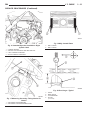
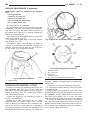
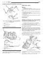
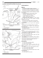
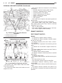
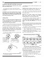
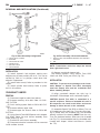
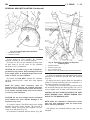
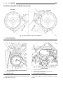
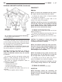
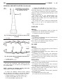
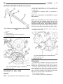
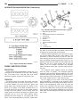
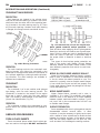
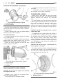
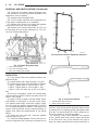
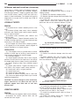
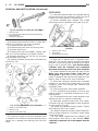
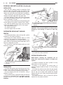
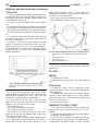
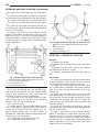
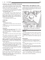
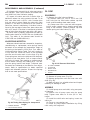
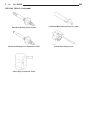
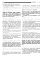
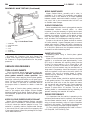
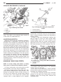
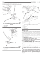
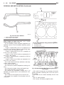
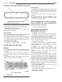
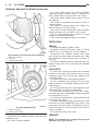
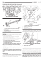
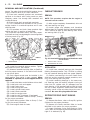
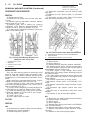
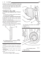
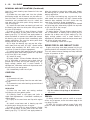
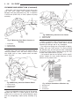
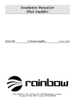
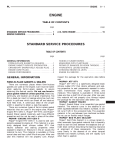
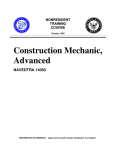
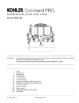
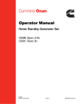
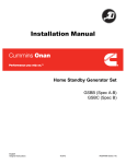
9 - 178
5.9L ENGINE
DN
REMOVAL AND INSTALLATION (Continued)
(2) Hold the oil pump base flush against mating
surface on No.5 main bearing cap. Finger tighten
pump attaching bolts. Tighten attaching bolts to 41
N·m (30 ft. lbs.) torque.
(3) Install the oil pan.
CRANKSHAFT OIL SEAL—FRONT
The oil seal can be replaced without removing the
timing chain cover provided the cover is not misaligned.
(1) Disconnect the negative cable from the battery.
(2) Remove vibration damper.
(3) If front seal is suspected of leaking, check front
oil seal alignment to crankshaft. The seal installation/alignment tool 6635, should fit with minimum
interference. If tool does not fit, the cover must be
removed and installed properly.
(4) Place a suitable tool behind the lips of the oil
seal to pry the oil seal outward. Be careful not to
damage the crankshaft seal bore of cover.
(5) Place the smaller diameter of the oil seal over
Front Oil Seal Installation Tool 6635 (Fig. 74). Seat
the oil seal in the groove of the tool.
Fig. 75 Position Tool and Seal onto Crankshaft
1 – SPECIAL TOOL 6635
2 – OIL SEAL
3 – TIMING CHAIN COVER
Fig. 74 Placing Oil Seal on Installation Tool 6635
1 – CRANKSHAFT FRONT OIL SEAL
2 – INSTALL THIS END INTO SPECIAL TOOL 6635
(6) Position the seal and tool onto the crankshaft
(Fig. 75).
(7) Using the vibration damper bolt, tighten the
bolt to draw the seal into position on the crankshaft
(Fig. 76).
(8) Remove the vibration damper bolt and seal
installation tool.
(9) Inspect the seal flange on the vibration
damper.
(10) Install the vibration damper.
(11) Connect the negative cable to the battery.
Fig. 76 Installing Oil Seal
1 – SPECIAL TOOL 6635
2 – TIMING CHAIN COVER
5.9L ENGINE
DN
9 - 179
REMOVAL AND INSTALLATION (Continued)
CRANKSHAFT OIL SEALS—REAR
The service seal is a 2 piece, viton seal. The upper
seal half can be installed with crankshaft removed
from engine or with crankshaft installed. When a
new upper seal is installed, install a new lower seal.
The lower seal half can only be installed with the
rear main bearing cap removed.
UPPER SEAL —CRANKSHAFT REMOVED
REMOVAL
(1) Remove the crankshaft. Discard the old upper
seal.
INSTALLATION
(1) Clean the cylinder block rear cap mating surface. Make sure the seal groove is free of debris.
(2) Lightly oil the new upper seal lips with engine
oil.
(3) Install the new upper rear bearing oil seal with
the white paint facing towards the rear of the engine.
(4) Position the crankshaft into the cylinder block.
(5) Lightly oil the new lower seal lips with engine
oil.
(6) Install the new lower rear bearing oil seal into
the bearing cap with the white paint facing towards
the rear of the engine.
(7) Apply 5 mm (0.20 in) drop of Mopart Gasket
Maker, or equivalent, on each side of the rear main
bearing cap (Fig. 77). DO NOT over apply sealant or
allow the sealant to contact the rubber seal. Assemble bearing cap to cylinder block immediately after
sealant application.
(8) To align the bearing cap, use cap slot, alignment dowel and cap bolts. DO NOT remove excess
material after assembly. DO NOT strike rear cap
more than 2 times for proper engagement.
(9) Clean and oil all cap bolts. Install all main
bearing caps. Install all cap bolts and alternately
tighten to 115 N·m (85 ft. lbs.) torque.
(10) Install oil pump.
(11) Apply Mopart Silicone Rubber Adhesive Sealant, or equivalent, at bearing cap to block joint to
provide cap to block and oil pan sealing (Fig. 78).
Apply enough sealant until a small amount is
squeezed out. Withdraw nozzle and wipe excess sealant off the oil pan seal groove.
(12) Install new front crankshaft oil seal.
(13) Immediately install the oil pan.
Fig. 78 Apply Sealant to Bearing Cap to Block Joint
1 – MOPAR SILICONE RUBBER ADHESIVE SEALANT NOZZLE
TIP
2 – SEALANT APPLIED
3 – CYLINDER BLOCK
4 – REAR MAIN BEARING CAP
UPPER SEAL —CRANKSHAFT INSTALLED
REMOVAL
(1) Remove the oil pan.
(2) Remove the oil pump from the rear main bearing cap.
(3) Remove the rear main bearing cap. Remove
and discard the old lower oil seal.
(4) Carefully remove and discard the old upper oil
seal.
Fig. 77 Sealant Application to Bearing Cap
1
2
3
4
–
–
–
–
MOPAR SILICONE RUBBER ADHESIVE SEALANT SLOTS
LOCTITE 518 (OR EQUIVALENT)
CAP ALIGNMENT SLOT
REAR MAIN BEARING CAP
INSTALLATION
(1) Clean the cylinder block mating surfaces before
oil seal installation. Check for burr at the oil hole on
the cylinder block mating surface to rear cap.
(2) Lightly oil the new upper seal lips with engine
oil. To allow ease of installation of the seal, loosen at
9 - 180
5.9L ENGINE
DN
REMOVAL AND INSTALLATION (Continued)
least the 2 main bearing caps forward of the rear
bearing cap.
(3) Rotate the new upper seal into the cylinder
block being careful not to shave or cut the outer surface of the seal. To assure proper installation, use the
installation tool provided with the kit. Install the
new seal with the white paint facing towards the
rear of the engine.
(4) Install the new lower rear bearing oil seal into
the bearing cap with the white paint facing towards
the rear of the engine.
(5) Apply 5 mm (0.20 in) drop of Mopart Gasket
Maker, or equivalent, on each side of the rear main
bearing cap (Fig. 77). DO NOT over apply sealant or
allow the sealant to contact the rubber seal. Assemble bearing cap to cylinder block immediately after
sealant application. Be sure the white paint faces
toward the rear of the engine.
(6) To align the bearing cap, use cap slot, alignment dowel and cap bolts. DO NOT remove excess
material after assembly. DO NOT strike rear cap
more than 2 times for proper engagement.
(7) Install the rear main bearing cap with cleaned
and oiled cap bolts. Alternately tighten ALL cap bolts
to 115 N·m (85 ft. lbs.) torque.
(8) Install oil pump.
(9) Apply Mopart Silicone Rubber Adhesive Sealant, or equivalent, at bearing cap to block joint to
provide cap to block and oil pan sealing (Fig. 78).
Apply enough sealant until a small amount is
squeezed out. Withdraw nozzle and wipe excess sealant off the oil pan seal groove.
(10) Immediately install the oil pan.
allow the sealant to contact the rubber seal. Assemble bearing cap to cylinder block immediately after
sealant application.
(6) To align the bearing cap, use cap slot, alignment dowel and cap bolts. DO NOT remove excess
material after assembly. DO NOT strike rear cap
more than 2 times for proper engagement.
(7) Install the rear main bearing cap with cleaned
and oiled cap bolts. Alternately tighten the cap bolts
to 115 N·m (85 ft. lbs.) torque.
(8) Install oil pump.
(9) Apply Mopart Silicone Rubber Adhesive Sealant, or equivalent, at bearing cap to block joint to
provide cap to block and oil pan sealing (Fig. 78).
Apply enough sealant until a small amount is
squeezed out. Withdraw nozzle and wipe excess sealant off the oil pan seal groove.
(10) Immediately install the oil pan.
ENGINE CORE OIL AND CAMSHAFT PLUGS
Engine core plugs have been pressed into the oil
galleries behind the camshaft thrust plate (Fig. 79).
This will reduce internal leakage and help maintain
higher oil pressure at idle.
LOWER SEAL
REMOVAL
(1) Remove the oil pan.
(2) Remove the oil pump from the rear main bearing cap.
(3) Remove the rear main bearing cap and discard
the old lower seal.
INSTALLATION
(1) Clean the rear main cap mating surfaces
including the oil pan gasket groove.
(2) Carefully install a new upper seal (refer to
Upper Seal Replacement - Crankshaft Installed procedure above).
(3) Lightly oil the new lower seal lips with engine
oil.
(4) Install a new lower seal in bearing cap with
the white paint facing the rear of engine.
(5) Apply 5 mm (0.20 in) drop of Mopart Gasket
Maker, or equivalent, on each side of the rear main
bearing cap (Fig. 77). DO NOT over apply sealant or
Fig. 79 Location of Cup Plugs in Oil Galleries
1 – CUP PLUGS
REMOVAL
(1) Using a blunt tool such as a drift or a screwdriver and a hammer, strike the bottom edge of the
cup plug (Fig. 80).
(2) With the cup plug rotated, grasp firmly with
pliers or other suitable tool and remove plug (Fig.
80).
5.9L ENGINE
DN
9 - 181
REMOVAL AND INSTALLATION (Continued)
Fig. 80 Core Hole Plug Removal
1
2
3
4
5
–
–
–
–
–
CYLINDER BLOCK
REMOVE PLUG WITH PLIERS
STRIKE HERE WITH HAMMER
DRIFT PUNCH
CUP PLUG
INSTALLATION
Thoroughly clean inside of cup plug hole in cylinder block or head. Be sure to remove old sealer.
Be certain the new plug is cleaned of all oil or
grease.
(1) Coat edges of plug and core hole with Mopart
Gasket Maker, or equivalent.
Fig. 81 Oil Pressure Relief Valve
1
2
3
4
5
–
–
–
–
–
OIL PUMP ASSEMBLY
COTTER PIN
RELIEF VALVE
RETAINER CAP
SPRING
(2) Remove oil pump cover (Fig. 82).
(3) Remove pump outer rotor and inner rotor with
shaft (Fig. 82).
(4) Wash all parts in a suitable solvent and inspect
carefully for damage or wear.
CAUTION: DO NOT drive cup plug into the casting,
as restricted coolant flow can result and cause serious engine problems.
(2) Using proper plug drive, drive cup plug into
hole. The sharp edge of the plug should be at least
0.50 mm (0.020 in.) inside the lead-in chamfer.
(3) It is not necessary to wait for curing of the
sealant. The cooling system can be filled and the
vehicle placed in service immediately.
DISASSEMBLY AND ASSEMBLY
OIL PUMP
DISASSEMBLE
(1) Remove the relief valve as follows:
(a) Remove cotter pin. Drill a 3.175 mm (1/8
inch) hole into the relief valve retainer cap and
insert a self-threading sheet metal screw.
(b) Clamp screw into a vise and while supporting oil pump, remove cap by tapping pump body
using a soft hammer. Discard retainer cap and
remove spring and relief valve (Fig. 81).
Fig. 82 Oil Pump
1 – INNER ROTOR AND SHAFT
2 – BODY
3 – DISTRIBUTOR DRIVESHAFT (REFERENCE)
4 – COTTER PIN
5 – RETAINER CAP
6 – SPRING
7 – RELIEF VALVE
8 – LARGE CHAMFERED EDGE
9 – BOLT
10 – COVER
11 – OUTER ROTOR
9 - 182
5.9L ENGINE
DN
DISASSEMBLY AND ASSEMBLY (Continued)
ASSEMBLE
(1) Install pump rotors and shaft, using new parts
as required.
(2) Position the oil pump cover onto the pump
body. Tighten cover bolts to 11 N·m (95 in. lbs.)
torque.
(3) Install the relief valve and spring. Insert the
cotter pin.
(4) Tap on a new retainer cap.
(5) Prime oil pump before installation by filling
rotor cavity with engine oil.
Check the pistons for taper and elliptical shape
before they are fitted into the cylinder bore (Fig. 83).
CLEANING AND INSPECTION
CYLINDER HEAD COVER
CLEANING
Clean cylinder head cover gasket surface.
Clean head rail, if necessary.
INSPECTION
Inspect cover for distortion and straighten, if necessary.
Check the gasket for use in head cover installation.
If damaged, use a new gasket.
CYLINDER HEAD ASSEMBLY
CLEANING
Clean all surfaces of cylinder block and cylinder
heads.
Clean cylinder block front and rear gasket surfaces
using a suitable solvent.
INSPECTION
Inspect all surfaces with a straightedge if there is
any reason to suspect leakage. If out-of-flatness
exceeds 0.00075 mm/mm (0.00075 inch/inch) times
the span length in inches in any direction, either
replace head or lightly machine the head surface.
FOR EXAMPLE: A 305 mm (12 inch) span is
0.102 mm (0.004 inch) out-of-flat. The allowable outof-flat is 305 X 0.00075 (12 X 0.00075) equals 0.23
mm (0.009 inch). This amount of out-of-flat is acceptable.
The cylinder head surface finish should be
1.78-3.00 microns (70-125 microinches).
PISTON AND CONNECTING ROD ASSEMBLY
INSPECTION
Check the crankshaft connecting rod journal for
excessive wear, taper and scoring.
Check the cylinder block bore for out-of-round,
taper, scoring and scuffing.
Fig. 83 Piston Measurements
1 – 49.53 mm
(1.95 IN.)
OIL PAN
CLEANING
Clean the block and pan gasket surfaces.
Trim or remove excess sealant film in the rear
main cap oil pan gasket groove. DO NOT remove
the sealant inside the rear main cap slots.
If present, trim excess sealant from inside the
engine.
Clean oil pan in solvent and wipe dry with a clean
cloth.
Clean oil screen and pipe thoroughly in clean solvent. Inspect condition of screen.
INSPECTION
Inspect oil drain plug and plug hole for stripped or
damaged threads. Repair as necessary.
Inspect oil pan mounting flange for bends or distortion. Straighten flange, if necessary.
OIL PUMP
INSPECTION
Mating surface of the oil pump cover should be
smooth. Replace pump assembly if cover is scratched
or grooved.
Lay a straightedge across the pump cover surface
(Fig. 84). If a 0.038 mm (0.0015 inch) feeler gauge
can be inserted between cover and straightedge,
pump assembly should be replaced.
5.9L ENGINE
DN
9 - 183
CLEANING AND INSPECTION (Continued)
PISTON MEASUREMENT CHART
PISTON
A DIA = PISTON
BORE
SIZE
DIAMETER
DIAMETER
MIN.
MAX.
MIN.
MAX.
mm
(in.)
mm
(in.)
mm
(in.)
mm (in.)
A
—
—
—
—
B
101.580
101.592
101.605
101.618
(3.9992)
(3.9997)
(4.0002)
(4.0007)
101.592
101.605
101.618
101.630
(3.9997)
(4.0002)
(4.0007)
(4.0012)
C
D
101.605
101.618
101.630
101.643
(4.0002)
(4.0007)
(4.0012)
(4.0017)
—
—
—
—
E
DESCRIPTION
SPECIFICATION
PISTON PIN
25.007 - 25.015 mm
BORE
(.9845 -.9848 in.)
Fig. 84 Checking Oil Pump Cover Flatness
1 – COVER
2 – STRAIGHT EDGE
3 – FEELER GAUGE
RING GROOVE
HEIGHT
OIL RAIL
4.033 - 4.058 mm
(.1588 -.1598 in.)
COMPRESSION
RAIL
1.529 - 1.554 mm
(.0602 -.0612 in.)
TOTAL FINISHED
470.8 6 2 grams
WEIGHT
(16.607 6.0706 ounces)
Fig. 85 Measuring Outer Rotor Thickness
Measure thickness and diameter of OUTER rotor.
If outer rotor thickness measures 20.9 mm (0.825
inch) or less or if the diameter is 62.7 mm (2.469
inches) or less, replace outer rotor (Fig. 85).
If inner rotor measures 20.9 mm (0.825 inch) or
less, replace inner rotor and shaft assembly (Fig. 86).
Fig. 86 Measuring Inner Rotor Thickness
9 - 184
5.9L ENGINE
DN
CLEANING AND INSPECTION (Continued)
Slide outer rotor into pump body. Press rotor to the
side with your fingers and measure clearance
between rotor and pump body (Fig. 87). If clearance
is 0.356 mm (0.014 inch) or more, replace oil pump
assembly.
Fig. 89 Measuring Clearance Over Rotors
1 – STRAIGHT EDGE
2 – FEELER GAUGE
Fig. 87 Measuring Outer Rotor Clearance in
Housing
1 – PUMP BODY
2 – OUTER ROTOR
3 – FEELER GAUGE
Install inner rotor and shaft into pump body. If
clearance between inner and outer rotors is 0.203
mm (0.008 inch) or more, replace shaft and both
rotors (Fig. 88).
Fig. 88 Measuring Clearance Between Rotors
1 – OUTER ROTOR
2 – FEELER GAUGE
3 – INNER ROTOR
Place a straightedge across the face of the pump,
between bolt holes. If a feeler gauge of 0.102 mm
(0.004 inch) or more can be inserted between rotors
and the straightedge, replace pump assembly (Fig.
89).
Inspect oil pressure relief valve plunger for scoring
and free operation in its bore. Small marks may be
removed with 400-grit wet or dry sandpaper.
The relief valve spring has a free length of approximately 49.5 mm (1.95 inches). The spring should
test between 19.5 and 20.5 pounds when compressed
to 34 mm (1-11/32 inches). Replace spring that fails
to meet these specifications (Fig. 90).
If oil pressure was low and pump is within specifications, inspect for worn engine bearings or other
reasons for oil pressure loss.
Fig. 90 Proper Installation of Retainer Cap
1 – RETAINER CAP
2 – CHAMFER
3 – COTTER KEY
5.9L ENGINE
DN
9 - 185
CLEANING AND INSPECTION (Continued)
CYLINDER BLOCK
SPECIFICATIONS
CLEANING
5.9L ENGINE SPECIFICATIONS
Clean cylinder block thoroughly and check all core
hole plugs for evidence of leaking.
INSPECTION
Examine block for cracks or fractures.
The cylinder walls should be checked for out-ofround and taper with Cylinder Bore Indicator Tool
C-119. The cylinder block should be bored and honed
with new pistons and rings fitted if:
• The cylinder bores show more than 0.127 mm
(0.005 inch) out-of-round.
• The cylinder bores show a taper of more than
0.254 mm (0.010 inch).
• The cylinder walls are badly scuffed or scored.
Boring and honing operation should be closely coordinated with the fitting of pistons and rings so specified clearances may be maintained.
Refer to Standard Service Procedures in the beginning of this Group for the proper honing of cylinder
bores.
INTAKE MANIFOLD
DESCRIPTION
SPECIFICATION
Engine Type
90° V-8 OHV
Bore and Stroke
101.6 x 90.9 mm
(4.00 x 3.58 in.)
Displacement
5.9L (360 c.i.)
Compression Ratio
9.1:1
Firing Order
1–8–4–3–6–5–7–2
Lubrication
Pressure Feed –
Full Flow Filtration
Cooling System
Liquid Cooled –
Forced Circulation
Cylinder Block
Cast Iron
Cylinder Head
Cast Iron
Crankshaft
Nodular Iron
Camshaft
Nodular Cast Iron
Combustion Chambers
Wedge High Swirl Valve
Shrouding
CLEANING
Clean manifold in solvent and blow dry with compressed air.
Clean cylinder block front and rear gasket surfaces
using a suitable solvent.
The plenum pan rail must be clean and dry (free of
all foreign material).
INSPECTION
Inspect manifold for cracks.
Inspect mating surfaces of manifold for flatness
with a straightedge.
EXHAUST MANIFOLD
Pistons
Aluminum Alloy w/strut
Connecting Rods
Forged Steel
Cylinder Compression
689.5 kPa
Pressure (Min.)
(100 psi)
DESCRIPTION
SPECIFICATION
CAMSHAFT
Bearing Diameter
No. 1
(2.000 – 2.001 in.)
CLEANING
Clean mating surfaces on cylinder head and manifold, wash with solvent and blow dry with compressed air.
No. 2
50.394 – 50.419 mm
(1.984 – 1.985 in.)
No. 3
50.013 – 50.038 mm
(1.969 – 1.970 in.)
INSPECTION
Inspect manifold for cracks, Inspect mating surfaces of manifold for flatness with a straight edge.
Seal surfaces must be flat within 0.1 mm (0.004 inch)
overall.
50.800 – 50.825 mm
No. 4
49.606 – 49.632 mm
(1.953 – 1.954 in.)
No. 5
39.688 – 39.713 mm
(1.5625 – 1.5635 in.)
9 - 186
5.9L ENGINE
DN
SPECIFICATIONS (Continued)
DESCRIPTION
SPECIFICATION
Bearing Journal Diameter
No. 1
DESCRIPTION
Bearing Clearance
50.749 – 50.775 mm
#1 Journal
(1.998 – 1.999 in.)
No. 2
50.343 – 50.368 mm
49.962 – 49.987 mm
Service Limit
#1 Journal
0.0381 mm (0.0015 in.)
Bearing Clearance
(1.967 – 1.968 in.)
#2-5 Journals
No. 4
49.555 – 49.581 mm
No. 5
39.637 – 39.662 mm
#2-5 Journals
(1.5605 – 1.5615 in.)
End Play
(1.951 – 1.952 in.)
0.013 – 0.038 mm
(0.0005 – 0.0015 in.)
(1.982 – 1.983 in.)
No. 3
SPECIFICATION
0.013 – 0.051 mm
(0.0005 – 0.002 in.)
Service Limit
0.064 mm (0.0025 in.)
0.051 – 0.178 mm
(0.002 – 0.007 in.)
Bearing to Journal
Clearance
Service Limit
Standard
0.0254 – 0.0762 mm
(0.001 – 0.003 in.)
Service Limit
0.127 mm
CYLINDER BLOCK
Cylinder Bore
Diameter
(0.005 in.)
Camshaft End Play
0.051 – 0.254 mm
(0.002 – 0.010 in.)
CONNECTING RODS
Piston Pin Bore Diameter
Out of Round (Max.)
0.025 mm (0.001 in.)
Taper (Max.)
0.025 mm (0.001 in.)
Lifter Bore
24.966 - 24.978 mm
0.152 - 0.356 mm
(0.006 - 0.014 in.)
CRANKSHAFT
Rod Journal
Diameter
53.950 – 53.975 mm
(2.124 – 2.125 in.)
Out of Round (Max.)
0.0254 mm (0.001 in.)
Taper (Max.)
0.0254 mm (0.001 in.)
Bearing Clearance
0.013 – 0.056 mm
(0.0005 – 0.0022 in.)
Service Limit
0.0762 mm (0.003 in.)
Diameter
Diameter
71.361 – 71.387 mm
(2.8095 – 2.8105 in.)
Out of Round (Max.)
0.127 mm (0.001 in.)
Taper (Max.)
0.0254 mm (0.001 in.)
22.99 – 23.01 mm
(0.9051 – 0.9059 in.)
Distributor Drive
Bushing—
(Press Fit)
Bushing to Bore
Interference
0.0127 – 0.3556 mm
(0.0005 – 0.0140 in.)
Shaft to Bushing
Clearance
0.0178 – 0.0686 mm
(0.0007 – 0.0027 in.)
CYLINDER HEAD AND VALVES
Valve Seat
Angle
Main Bearing Journal
101.60 – 101.65 mm
(4.000 – 4.002 in.)
(0.9829 - 0.9834 in.)
Side Clearance
0.254 mm (0.010 in.)
Runout (Max.)
Width (Finish) – Intake
44.25° – 44.75°
0.0762 mm (0.003 in.)
1.016 – 1.524 mm
(0.040 – 0.060 in.)
Width (Finish) – Exhaust
1.524 – 2.032 mm
(0.060 – 0.080 in.)
5.9L ENGINE
DN
9 - 187
SPECIFICATIONS (Continued)
DESCRIPTION
SPECIFICATION
DESCRIPTION
Valves
SPECIFICATION
HYDRAULIC TAPPETS
Face Angle
Head Diameter – Intake
Head Diameter –
Exhaust
Length (Overall) – Intake
43.25° – 43.75°
Body Diameter
47.752 mm (1.88 in.)
(0.9035 – 0.9040 in.)
41.072 (1.617 in.)
Clearance (to bore)
Dry Lash
Push Rod Length
Lift (@ zero lash) –
Exhaust
10.592 mm (0.417 in.)
Stem Diameter – Intake
Stem Diameter – Exhaust
9.423 – 9.449 mm
9.500 – 9.525 mm
(0.374 – 0.375 in.)
Stem to Guide
Clearance—
Intake
Curb Idle (Min.*)
(0.001 – 0..003 in.)
Setting
Switch Actuating
Pressure
* If oil pressure is zero at curb idle, DO NOT RUN
ENGINE.
OIL PUMP
Cover Out of Flat (Max.)
0.0381 mm (0.0015 in.)
Inner Rotor Thickness
(Min.)
20.955 mm (0.825 in.)
Outer Rotor Clearance
(Max.)
0.3556 mm (0.014 in.)
Outer Rotor Diameter
(Min.)
62.7126 mm (2.469 in.)
378 N @ 41.66 mm
Outer Rotor Thickness
(Min.)
20.955 mm (0.825 in.)
(85 lbs. @ 1.64 in.)
Tip Clearance between
Rotors—
(0.002 – 0.004 in.)
0.4318 (0.017 in.)
Valve Springs
Spring Tension – (valve
closed)
Spring Tension – (valve
open)
34.5 – 48.3 kPa (5 – 7
psi)
0.1016 mm (0.004 in.)
0.0508 – 0.1016 mm
Free Length
62 – 103 kPa (9 – 15 psi)
Clearance over Rotors
(Max.)
Stem to Guide
Clearance—
Service Limit
207 – 552 kPa (30 – 80
psi)
Oil Pressure Bypass
Valve—
0.0254 – 0.0762 mm
Exhaust
41.4 kPa (6 psi)
9.449 – 9.474 mm
(0.371 – 0.372 in.)
Guide Bore
OIL PRESSURE
3000 rpm
(0.372 – 0.373 in.)
175.64 – 176.15 mm
(6.915 – 6.935 in.)
(4.978 – 5.012 in.)
10.414 mm (0.410 in.)
1.524 – 5.334 mm
(0.060 – 0.210 in.)
126.44 – 127.30 mm
Lift (@ zero lash) –
Intake
0.0279 – 0.0610 mm
(0.0011 – 0.0024 in.)
126.21 – 126.85 mm
(4.969 – 4.994 in.)
Length (Overall) –
Exhaust
22.949 – 22.962 mm
49.962 mm (1.967 in.)
890 N @ 30.89 mm
(Max.)
(200 lbs. @ 1.212 in.)
Number of Coils
6.8
Installed Height
41.66 mm (1.64 in.)
0.2032 mm (0.008 in.)
9 - 188
5.9L ENGINE
DN
SPECIFICATIONS (Continued)
DESCRIPTION
SPECIFICATION
PISTONS
Clearance at Top of Skirt
0.013 – 0.038 mm
DESCRIPTION
SPECIFICATION
Oil Ring (Steel Rails) –
Max.
0.447 –0.473 mm
(0.018 – 0.019 in.)
(0.0005 – 0.0015 in.)
Land Clearance (Diam.)
(0.020 – 0.026 in.)
Piston Length
VALVE TIMING
0.508 – 0.660 mm
Exhaust Valve
81.03 mm (3.19 in.)
Piston Ring Groove
Depth—
#1&2
4.761 – 4.912 mm
Piston Ring Groove
Depth—
3.996 – 4.177 mm
(0.157 – 0.164 in.)
Weight
582 – 586 grams
(20.53 – 20.67 oz.)
PISTON PINS
Clearance in Piston
33°
Opens (BBDC)
56°
Duration
269°
Closes (ATDC)
62°
Opens (BBDC)
7°
Intake Valve
(0.187 – 0.193 in.)
#3
Closes (ATDC)
Duration
249°
Valve Overlap
41°
OVERSIZE AND UNDERSIZE ENGINE
COMPONENT MARKINGS CHART
ITEM
U/S
(O/S)
IDENTIFICATION
IDENTIFICATION
LOCATION
Crankshaft
Journals
0.0254
mm
(0.001
in.) U/S
R or M M-2-3
ect.
(indicating
No. 2 and 3
main bearing
journal)
and/or R-1-4
ect.
(indicating
No. 1 and 4
connecting
rod journal)
Milled flat on
No. 8
crankshaft
counterweight.
Hydraulic
Tappets
0.2032
mm
(0.008
in.)
(O/S)
l
Diamondshaped stamp
top pad - front
of engine and
flat ground on
outside
surface of
each O/S
tappet bore.
Valve
Stems
0.127
mm
(0.005
in.)
(O/S)
X
Milled pad
adjacent to
two tapped
holes (3/8 in.)
on each end
of cylinder
head.
0.006 – 0.019 mm
(0.00023 – 0.00074 in.)
Diameter
25.007 – 25.015 mm
(0.9845 – 0.9848 in.)
End Play
NONE
Length
67.8 – 68.3 mm
(2.67 – 2.69 in.)
PISTON RINGS
Ring Gap
Compression Ring (Top)
0.30 – 0.55 mm
(0.012 – 0.022 in.)
Compression Ring (2nd)
0.55 – 0.80 mm
(0.022 – 0.031 in.)
Oil Control (Steel Rails)
0.381 – 1.397 mm
(0.015 – 0.055 in.)
Ring Side Clearance
Compression Rings
0.040 – 0.085 mm
(0.0016 – 0.0033 in.)
Oil Ring (Steel Rails)
0.05 – 0.21 mm
(0.002 – 0.008 in.)
Ring Width
Compression rings
1.530 – 1.555 mm
(0.060 – 0.061 in.)
DN
5.9L ENGINE
9 - 189
N·m
Ft.
In.
SPECIFICATIONS (Continued)
SPECIFICATIONS
DESCRIPTION
TORQUE CHART 5.9L ENGINE
DESCRIPTION
N·m
Ft.
In.
Lbs.
Lbs.
Camshaft Sprocket—Bolt
68
50
—
Camshaft Thrust Plate—Bolts
24
—
210
Timing Chain Case Cover—
Bolts
41
30
—
Connecting Rod Cap—Bolts
61
45
—
Main Bearing Cap—Bolts
115
85
—
Crankshaft Pulley—Bolts
24
—
210
Step 1
68
50
—
Step 2
143
105
—
Cylinder Head Cover—Bolts
11
—
95
Engine Support Bracket to
Block—
41
30
—
Cylinder Head—Bolts
Bolts (4WD)
Exhaust Manifold to Cylinder
Head—
34
25
—
Lbs.
Lbs.
68
50
—
68
50
—
41
30
—
41
30
—
Rocker Arm—Bolts
28
21
—
Spark Plugs
41
30
—
Starter Motor—Mounting Bolts
68
50
—
Thermostat Housing—Bolts
25
—
225
Throttle Body—Bolts
23
—
200
Torque Converter Drive
Plate—Bolts
31
—
270
Transfer Case to Insulator
204
105
—
68
50
—
Vibration Damper—Bolt
244
180
—
Water Pump to Timing Chain
41
30
—
Rear Insulator to
Transmission—
Bolts (4WD)
Rear Insulator Bracket—Bolts
(4WD Automatic)
Rear Support Bracket to
Crossmember Flange—Nuts
Rear Support Plate to
Transfer
Case—Bolts
Mounting Plate—Nuts
Bolts/Nuts
Flywheel—Bolts
75
55
—
Front Insulator—Through
bolt/nut
95
70
—
Front Insulator to Support
Bracket
Transmission Support
Bracket—
Bolts (2WD)
Case Cover—Bolts
—Stud Nut (4WD)
41
30
—
—Through Bolt/Nut (4WD)
102
75
—
Front Insulator to Block—
Bolts (2WD)
95
70
—
SPECIAL TOOLS
Generator—Mounting Bolt
41
30
—
5.9L ENGINE
Intake Manifold—Bolts
Refer to Procedure
Oil Pan—Bolts
24
—
215
Oil Pan—Drain Plug
34
25
—
Oil Pump—Attaching Bolts
41
30
—
Oil Pump Cover—Bolts
11
—
95
Rear Insulator to Bracket—
68
50
—
41
30
—
Through-Bolt (2WD)
Rear Insulator to
Crossmember
Oil Pressure Gauge C-3292
Support Bracket—Nut (2WD)
Rear Insulator to
Crossmember—
Nuts (4WD)
68
50
—
9 - 190
5.9L ENGINE
DN
SPECIAL TOOLS (Continued)
Engine Support Fixture C-3487–A
Dial Indicator C-3339
Valve Spring Compressor MD-998772–A
Puller C-3688
Adapter 6633
Puller 1026
Adapter 6716A
Crankshaft Damper Removal Insert 8513
Valve Guide Sleeve C-3973
Front Oil Seal Installer 6635
5.9L ENGINE
DN
9 - 191
SPECIAL TOOLS (Continued)
Cam Bearing Remover/Installer C-3132–A
Piston Ring Compressor C-385
Camshaft Holder C-3509
Crankshaft Main Bearing Remover C-3059
Distributor Bushing Puller C-3052
Cylinder Bore Gauge C-119
Distributor Bushing Driver/Burnisher C-3053
Pressure Tester Kit 7700
Bloc–Chek–Kit C-3685–A