1
AD3
(Machine Code: A133)
IMPORTANT SAFETY NOTICES
PREVENTION OF PHYSICAL INJURY
1. Before disassembling or assembling parts of the copier and peripherals,
make sure that the copier power cord is unplugged.
2. The wall outlet should be near the copier and easily accessible.
3. Note that some components of the copier and the paper tray unit are
supplied with electrical voltage even if the main switch is turned off.
4. If any adjustment or operation check has to be made with exterior covers
off or open while the main switch is turned on, keep hands away from
electrified or mechanically driven components.
5. If the start key is pressed before the copier completes the warm-up period
(Start key starts blinking red and green alternatively), keep hands away
from the mechanical and the electrical components as the copier starts
making copies as soon as the warm-up period is completed.
6. The inside and the metal parts of the fusing unit become extremely hot
while the copier is operating. Be careful to avoid touching those
components with your bare hands.
HEALTH SAFETY CONDITIONS
1. Never operate the copier without the ozone filters installed.
2. Always replace the ozone filters with the specified ones at the specified
intervals.
3. Toner and developer are non-toxic, but if you get either of them in your
eyes by accident, it may cause temporary eye discomfort. Try to remove
with eye drops or flush with water as first aid. If unsuccessful, get medical
attention.
OBSERVANCE OF ELECTRICAL SAFETY STANDARDS
1. The copier and its peripherals must be installed and maintained by a
customer service representative who has completed the training course
on those models.
CATION
2. The RAM board on the system control board has a lithium battery
which can explode if replaced incorrectly. Replace the battery only
with an identical one. The manufacturer recommends replacing
the entire RAM board. Do not recharge or burn this battery. Used
batteries must be handled in accordance with local regulations.
SAFETY AND ECOLOGICAL NOTES FOR DISPOSAL
1. Do not incinerate the toner bottle or the used toner. Toner dust may ignite
suddenly when exposed to open flame.
2. Dispose of used toner, developer, and organic photoconductor according
to local regulations. (These are non-toxic supplies.)
3. Dispose of replaced parts in accordance with local regulations.
4. When keeping used lithium batteries in order to dispose of them later, do
not put more than 100 batteries per sealed box. Storing larger numbers or
not sealing them apart may lead to chemical reactions and heat build-up.
LASER SAFETY
The Center for Devices and Radiological Health (CDRH) prohibits the repair
of laser-based optical units in the field. The optical housing unit can only be
repaired in a factory or at a location with the requisite equipment. The laser
subsystem is replaceable in the field by a qualified Customer Engineer. The
laser chassis is not repairable in the field. Customer engineers are therefore
directed to return all chassis and laser subsystems to the factory or service
depot when replacement of the optical subsystem is required.
WARNING
Use of controls, or adjustment, or performance of procedures other than
those specified in this manual may result in hazardous radiation exposure.
WARNING FOR LASER UNIT
WARNING: Turn off the main switch before attempting any of the
procedures in the Laser Unit section. Laser beams
can seriously damage your eyes.
CAUTION MARKING:
For 115V version
For 230V version
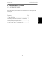
SECTION 1
OVERALL MACHINE
INFORMATION
22 March 1996
SPECIFICATIONS
Overall
Information
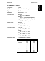
1. SPECIFICATIONS
Configuration:
Desktop
Copy Process:
Dry electrostatic transfer system
Originals:
Sheet/Book
Original Size:
Maximum A3/11" x 17"
Copy Paper Size:
Maximum
A3/11" x 17" (Paper tray)
Minimum
A5/81/2" x 51/2" sideways (Paper tray)
A6/51/2" x 81/2" lengthwise (By-pass)
LCT
A4/11" x 81/2" sideways only
Duplex Copying:
Maximum
A3/11" x 17"
Minimum
A5/81/2" x 51/2" sideways
Copy Paper Weight:
Paper tray:
60 ~ 105 g/m2, 16 ~ 24 lb
By-pass:
60 ~ 157 g/m2, 16 ~ 42 lb
LCT:
60 ~ 128 g/m2, 16 ~ 34 lb
Duplex copying:
64 ~ 105 g/m2, 17 ~ 24 lb
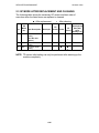
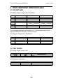
Reproduction Ratios:
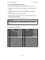
5 Enlargement and 7 Reduction
Enlargement
Full size
Reduction
1-1
A4/A3 Version
400%
200%
141%
122%
115%
100%
93%
87%
82%
71%
65%
50%
25%
LT/DLT Version
400%
200%
155%
129%
121%
100%
93%
85%
77%
74%
65%
50%
25%
SPECIFICATIONS
22 March 1996
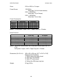
Zoom:
25% to 400% in 1% steps
Power Source:
120V/60Hz:
More than 12 A (for North America)
220V ~ 240V/50Hz:
More than 7 A (for Europe)
220V ~ 240V/60Hz:
More than 7 A (for Asia)
Power Consumption:
Maximum
Copying
Warm-up
Stand-by
Copier Only
Less than 1.44 kW
Less than 1.20 kW
Less than 0.88 kW
Less than 0.20 kW
Full System
Less than 1.44 kW
Less than 1.20 kW
Less than 0.90 kW
Less than 0.22 kW
NOTE: 1) Full System: Copier + ADF + Paper Tray Unit + Finisher
Noise Emission:
Copier Only
1. Sound Power Level
Copying
66.0 dB(A)
Stand-by
40.0 dB(A)
2. Sound Pressure Level at the Operator Position
Copying
54 dB(A)
Stand-by
25 dB(A)
Full System
69.0 dB(A)
40.0 dB(A)
59 dB(A)
25 dB(A)
NOTE: The above measurements are to be made in accordance with ISO
7779.
Full System: Copier + ADF + Paper Tray Unit + Finisher.
Dimensions (W x D x H):
880 x 655 x 602 mm (34.7" x 25.8" x 23.8")
Measurement Conditions
1) With by-pass feed table closed
2) With copy tray attached
3) With LCT cover closed
4) Without the 500-sheet copy tray
Weight:
95 kg (210 lb)
1-2
22 March 1996
SPECIFICATIONS
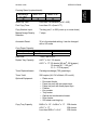
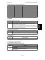
A4 sideways/
11" x 81/2"
40
A3/11" x 17"
B4/81/2" x 14"
18
26
Overall
Information
Copying Speed (copies/minute):
Warm-Up Time
Less than 140 seconds (20°C, 68°F)
First Copy Time:
Less than 5.2 s (from LCT)
Copy Number Input:
Ten-key pad, 1 to 999 (count up or count down)
Manual Image Density
Selection:
7 steps
Automatic Reset:
30 s is the standard setting; it can be changed
with a UP mode.
Copy Paper Capacity:
Paper Tray
About 500 sheets x1
By-pass Feed
About 40 sheets
LCT
About 1000 sheets
Hard Disk:
1 GB, Fast SCSI-2
Duplex Tray Capacity
A4/11" x 81/2": 50 sheets
A3/11" x 17": 50 sheets (80 g/m2, 20 lb paper)
30 sheets (81 ~ 105 g/m2,
21.5 ~ 27.9 lb paper)
Toner Replenishment:
Cartridge exchange (700 g/cartridge)
Toner Yield:
20K copies (A4, 6% full black, ID Level 4)
Optional Equipment:
Copy Tray Capacity
•
•
•
•
•
•
•
•
•
•
Platen cover
Document feeder
Paper tray unit with two paper trays
Paper tray unit with three paper trays
Finisher
Key counter
Tray heater
Optical anti-condensation heater
Drum heater
500-sheet receiving tray
B4/81/2" x 14" ~ A4/81/2" x 11"
A3\11" x 17"
Less than B5/51/2" x 81/2":
1-3
500 sheets
200 sheets
200 sheets
MACHINE CONFIGURATION
22 March 1996
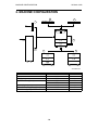
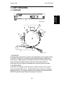
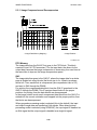
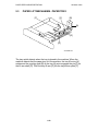
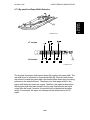
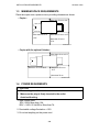
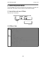
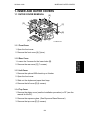
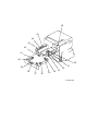
2. MACHINE CONFIGURATION
1
2
7
3
6
5
4
A133V500.wmf
Item
Copier
ADF (Option)
Paper Feed Unit (Option)
Machine Code
A133
A548
A549
A550
A612
A615
A381
Finisher (Option)
500-sheet Receiving Tray (Option)
Platen Cover (Option)
1-4
No.
3
1
5
4
6
7
2
22 March 1996
PAPER PATH
3.1
Overall
Information
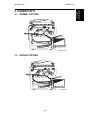
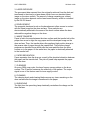
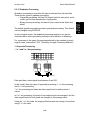
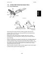
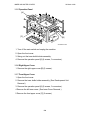
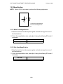
3. PAPER PATH
NORMAL COPYING
A133V501.wmf
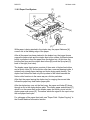
3.2
DUPLEX COPYING
A133V502.wmf
1-5
MECHANICAL COMPONENT LAYOUT
22 March 1996
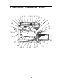
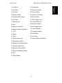
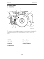
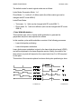
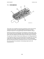
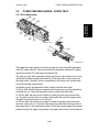
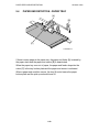
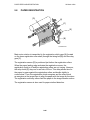
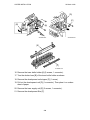
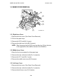
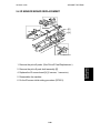
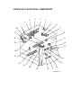
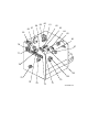
4. MECHANICAL COMPONENT LAYOUT
1
2
3
4
5
6 7 8 9 10
11 12
13
14
15
35
16
34
17
33
18
32
19
31
20
30
21
29
28
27
26
25
1-6
24
23
22
A133V503.wmf
MECHANICAL COMPONENT LAYOUT
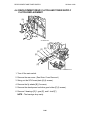
1. 3rd. Mirror
22. Feed Roller
2. 2nd. Mirror
23. Separation Roller
3. 1st. Mirror
24. Pick-up Roller
4. Exposure Lamp
25. Duplex Feed Roller
5. Polygonal Mirror Motor
26. Bottom Plate
6. Fθ Lenses
27. Side Jogger Fence
7. Cleaning Unit
28. Transfer Belt Unit
8. Lens
29. Entrance Rollers
9. Charge Corona Unit
30. End Jogger Fence
10. Barrel Toroidal Lens (BTL)
31. Pressure Roller
11. CCD
32. Fusing Exit Roller
12. Mirror
33. Exit Rollers
13. Drum
34. Hot Roller
14. Development Unit
35. Optics Exhaust Fan Motor
15. Registration Rollers
16. By-pass Feed Relay Roller
17. By-pass Feed Roller
18. By-pass Pick-up Roller
19. By-pass Separation Roller
20. LCT
21. Relay Rollers
1-7
Overall
Information
22 March 1996
ELECTRICAL COMPONENT DESCRIPTIONS
22 March 1996
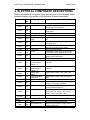
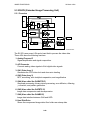
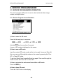
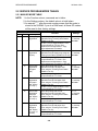
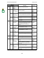
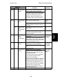
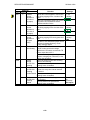
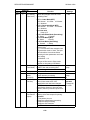
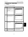
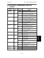
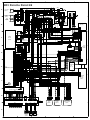
5. ELECTRICAL COMPONENT DESCRIPTIONS
Refer to the electrical component layout and the point-to-point diagram on the
waterproof paper in the pocket for the locations of these components.
Symbol
Index
Description
No.
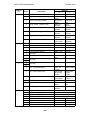
Printed Circuit Boards
SCU
PCB1
90
PCB2
89
PCB3
PCB4
92
93
PCB5
80
PCB6
85
PCB7
87
PCB8
79
PCB9
81
PCB10
84
PCB11
94
PCB12
86
PCB13
83
PCB14
31
PCB15
33
PCB16
40
PCB17
N/A
PCB18
51
PCB19
91
PCB20
7
AC Drive
DC Power Supply
BCU
Charge High Voltage
Supply
High Voltage Control
Operation Panel
Scanner Drive
EX-IPU
SBU
Lamp Stabilizer
Main Scan
Synchronization
Detector - 1
Main Scan
Synchronization
Detector - 2
Transfer High
Voltage
Development Bias
Power Pack
Duplex Control
Liquid Crystal Display
LCT Interface
Relay Board
Motors
M1
57
M2
66
Note
Laser Diode Drive
Main
Toner Bottle Drive
Controls all copier functions both directly or
through other control boards.
Provides ac power to the exposure lamp and
fusing lamps.
Provides dc power.
Controls the mechanical parts of the printer.
Supplies high voltage to the charge corona
unit.
Controls the high voltage boards and the
quenching lamp.
Controls the touch panel display and LED
matrix, and monitors the key matrix.
Drives the scanner motor.
Processes the video signal from the SBU
and sends the video signal to the LD unit.
Contains the CCD, and outputs a video
signal to the EX-IPU board.
Provides dc power for the exposure lamp.
Detects the laser beam at the start of the
main scan.
Detects the laser beam at the end of the
main scan.
Supplies high voltage to the transfer belt.
Supplies high voltage to the development
roller.
Controls the operation of the duplex tray.
Controls the guidance display and displays
guidance for machine operation.
Interfaces the LCT control signal between
the main board and the LCT.
Switches ac power to either the dc drive
board (if the main switch is on) or to the
heaters (if the main switch is off).
Controls the laser diode.
Drives the main body components.
Rotates the toner bottle to supply toner to
the toner supply unit.
1-8
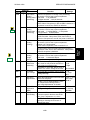
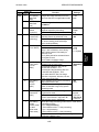
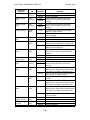
ELECTRICAL COMPONENT DESCRIPTIONS
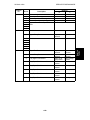
Symbol
Index
No.
M3
73
M4
M5
M6
M7
M8
56
48
74
65
78
M9
60
M10
55
M11
36
M12
39
M13
38
M14
75
M15
68
Description
Note
Tray Lift
Raises the bottom plate in the paper tray.
Polygonal Mirror
LCT Lift
Optics Exhaust Fan
IPU Fan
Exhaust Fan
Ozone Fan
Turns the polygonal mirror.
Lifts up and lowers the LCT bottom plate.
Removes heat from the optics unit.
Removes heat from the IPU board.
Removes heat from around the fusing unit.
Removes ozone-laden air from inside the
machine.
Drives the 1st and 2nd scanners (dc stepper
motor).
Drives the feed roller and moves the bottom
plate up and down.
Drives the end fence jogger to square the
paper stack.
Drives the side fence jogger to square the
paper stack.
Removes heat from around the DC drive
board.
Provides air flow around the charge corona
unit section.
Scanner Drive
Duplex Feed
End Fence Jogger
Side Fence Jogger
DC Drive Board Fan
Charge Inlet Fan
Sensors
S1
13
S2
15
S3
18
By-pass Feed Paper
Width
By-pass Feed Paper
End
Tray Paper End
Upper Relay
S4
46
S5
16
S6
47
S7
49
S8
50
S9
12
S10
19
S11
29
S12
30
Tray Upper Limit
Lower Relay
LCT Lower Limit
LCT Paper End
LCT Upper Limit
Registration
Image Density
(ID)
Toner Density
(TD)
Informs the CPU what width paper is in the
by-pass feed table.
Informs the CPU that there is no paper in the
by-pass tray.
Informs the CPU when the paper tray runs
out of paper.
Detects the leading edge of paper from the
paper tray and duplex unit to determine the
stop timing of the paper feed clutch and
duplex feed motor. Also detects misfeeds.
Detects the height of the paper stack in the
paper tray to stop the upper tray lift motor.
Detects misfeeds.
Sends a signal to the CPU to stop lowering
the LCT bottom plate.
Informs the CPU when the LCT runs out of
paper.
Signals the CPU to stop lifting the LCT
bottom plate.
Detects the leading edge of the copy paper
to determine the stop timing of the paper
feed clutch, and detects misfeeds.
Detects the density of various patterns on
the drum during process control.
Detects the amount of toner inside the
development unit.
1-9
Overall
Information
22 March 1996
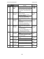
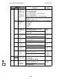
ELECTRICAL COMPONENT DESCRIPTIONS
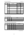
Symbol
Index
No.
S13
1
S14
8
S15
9
S16
24
S17
6
S18
32
S19
28
S20
10
S21
2
S22
34
S23
35
S24
42
S25
37
S26
41
S27
23
S28
Switches
14
SW1
11
SW2
53
SW3
20
SW4
54
SW5
SW6
52
27
SW7
26
22 March 1996
Description
Scanner HP
Original Length-1
Original Length-2
Fusing Exit
Platen Cover
Toner End
Auto Response
Transfer Belt
Position
Original Width
Duplex Paper End
Duplex Turn
Duplex Entrance
Side Fence Jogger
HP
End Fence Jogger
HP
Toner Overflow
By-pass Relay
By-pass Feed Table
Tray Down
Tray Paper Size
LCT
LCT Cover
Main
Front Cover Safety
Note
Informs the CPU when the 1st and 2nd
scanners are at the home position.
Detects the length of the original. This is one
of the APS (Auto Paper Select) sensors.
Detects the length of the original. This is one
of the APS (Auto Paper Select) sensors.
Detects misfeeds.
Informs the CPU whether the platen cover is
up or down (related to APS/ARE functions).
ARE: Auto Reduce and Enlarge
Instructs the CPU to add toner to the toner
supply unit, and detects toner end conditions.
Returns the operation panel display and exits
from the energy saver mode.
Informs the CPU of the current position of
the transfer belt unit.
Detects the width of the original. This is one
of the APS (Auto Paper Select) sensors.
Detects paper in the duplex tray.
Detects the trailing edge of the copy paper to
determine the jogging timing, and detects
misfeeds.
Detects misfeeds.
Detects the home position of the duplex side
fence jogger.
Detects the home position of the duplex end
fence jogger.
Detects when the used toner collection bottle
is full.
Detects misfeeds.
Detects whether the by-pass feed table is
open or closed.
Sends a signal to the CPU to lower the LCT
bottom plate.
Determines what size of paper is in the
paper tray.
Cuts the dc power line and detects whether
the LCT is open or not.
Cuts the dc power line of the LCT lift motor.
Supplies power to the copier.
Cuts the dc power line and detects whether
the front cover is open or not.
Magnetic Clutches
CL1
61
CL2
59
Toner Supply
Development
Turns the toner supply roller to supply toner
to the development unit.
Drives the development roller.
1-10
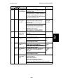
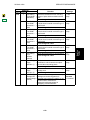
ELECTRICAL COMPONENT DESCRIPTIONS
Symbol
Index
No.
CL3
76
CL4
58
CL5
63
CL6
CL7
CL8
Solenoids
71
72
62
SOL1
67
SOL2
77
SOL3
64
SOL4
69
SOL5
70
Description
Transfer Belt Lift
Registration
By-pass Feed
Relay
Paper Feed
By-pass Relay
By-pass Pick-up
Junction Gate
LCT Pick-up
Pick-up
Separation
Note
Controls the touch and release movement of
the transfer belt unit.
Drives the registration rollers.
Starts paper feed from the by-pass feed
table or LCT.
Drives the relay rollers.
Starts paper feed from the paper tray.
Drives the by-pass relay rollers.
Drops the pick-up roller to the by-pass paper
feed position. When paper is fed from the
LCT, this solenoid assists SOL3.
Moves the junction gate to direct copies to
the duplex tray or to the paper exit.
Drops the pick-up roller all the way down to
the LCT paper feed position from the
by-pass paper feed position.
Controls the up/down movement of the
pick-up roller in the paper tray.
Controls the up/down movement of the
separation roller at the paper tray feed
station.
Lamps
L1
3
L2
43
L3
88
Exposure
Fusing
Quenching
Applies high intensity light to the original for
exposure.
Provides heat to the hot roller.
Neutralizes any charge remaining on the
drum surface after cleaning.
Heaters
Drum (option)
H1
21
H2
5
H3
22
Optics
Anti-condensation
(option)
Tray
(option)
Turns on when the main switch is off to
prevent moisture from forming around the
drum.
Turns on when the main switch is off to
prevent moisture from forming on the optics.
Turns on when the main switch is off to keep
paper dry in the paper tray.
Thermistors
TH1
45
Fusing
Monitors the temperature at the central area
of the hot roller.
Fusing
Provides back-up overheat protection in the
fusing unit.
Exposure Lamp
Opens the exposure lamp circuit if the 1st
scanner overheats.
Thermofuses
TF1
44
Thermoswitch
TS1
4
1-11
Overall
Information
22 March 1996
ELECTRICAL COMPONENT DESCRIPTIONS
Symbol
Index
No.
22 March 1996
Description
Note
Counters
CO1
25
CO2
N/A
Total
Key
(option)
Keeps track of the total number of copies
made.
Used for control of authorized use. The
copier will not operate until it is installed.
Others
CB1
17
HDD
82
Circuit Breaker
(220 ~ 240V
machines only)
Hard Disk Drive
Provides back-up high current protection for
electrical components.
Scanned image data is compressed and
held here temporarily during copying; also
holds user stamp data.
1-12
22 March 1996
DRIVE LAYOUT
1
Overall
Information
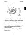
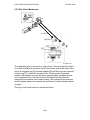
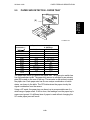
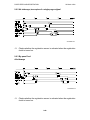
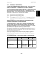
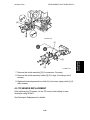
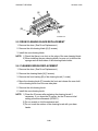
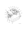
6. DRIVE LAYOUT
3
2
4
5
6
15
7
14
13
8
A133V504.wmf
12
10
11
9
1. Toner Supply Clutch
9. Transfer Belt Drive Gear
2. Development Clutch
10. Cleaning Blade Drive Gear
3. Drum Drive Pulley
11. Registration Clutch
4. Main Motor
12. Paper Feed Clutch
5. Scanner Drive Motor
13. Relay Clutch
6. Fusing Drive Gear
14. By-pass Feed Clutch
7. Exit Drive Gear
15. By-pass Relay Clutch
8. Toner Collection Bottle Drive Gear
1-13
SECTION 2
DETAILED
SECTION DESCRIPTIONS
22 March 1996
COPY PROCESS
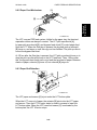
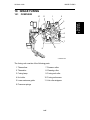
1. COPY PROCESS
1
A133D591.wmf
9
2
3
4
8
7
6
5
A133D593.wmf
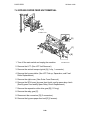
1. EXPOSURE
A halogen lamp exposes the original. Light reflected from the original passes
to the CCD, where it is converted into an analog data signal. This data is
converted to a digital signal, processed, and stored on the hard disk. At the
time of printing, the data is retrieved and sent to the laser diode. For
multi-copy runs, the original is scanned once only and stored to the disk.
2. DRUM CHARGE
In the dark, the charge corona unit gives a negative charge to the organic
photo-conductive (OPC) drum. The grid plate ensures that corona charge is
applied uniformly. The charge remains on the surface of the drum because
the OPC layer has a high electrical resistance in the dark.
2-1
Detailed
Descriptions
1.1 OVERVIEW
COPY PROCESS
22 March 1996
3. LASER EXPOSURE
The processed data scanned from the original is retrieved from the disk and
transferred to the drum by a laser beam, which forms an electrical latent
image on the drum surface. The amount of charge remaining as a latent
image on the drum depends on the laser beam intensity, which is controlled
by the EX-IPU board.
4. DEVELOPMENT
The magnetic developer brush on the development rollers comes in contact
with the latent image on the drum surface. Toner particles are
electrostatically attracted to the areas of the drum surface where the laser
reduced the negative charge on the drum.
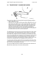
5. IMAGE TRANSFER
Paper is fed to the area between the drum surface and the transfer belt at the
proper time so as to align the copy paper and the developed image on the
drum surface. Then, the transfer bias roller applies a high positive charge to
the reverse side of paper through the transfer belt. This positive charge
produces an electrical force which pulls the toner particles from the drum
surface on to the paper. At the same time, the paper is electrically attracted
to the transfer belt.
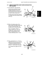
6. PAPER SEPARATION
Paper separates from the drum as a result of the electrical attraction between
the paper and the transfer belt. The pick-off pawls help separate the paper
from the drum.
7. ID SENSOR
On every 200th copy cycle, the laser forms a sensor pattern on the drum
surface. The ID sensor measures the reflectivity of the pattern. The output
signal is one of the factors used for toner supply control.
8. CLEANING
The cleaning brush and cleaning blade remove any toner remaining on the
drum surface after the image is transferred to the paper.
9. QUENCHING
The light from the quenching lamp electrically neutralizes the charge on the
drum surface.
2-2
22 March 1996
PROCESS CONTROL
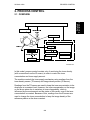
2. PROCESS CONTROL
Detailed
Descriptions
2.1 OVERVIEW
7RQHU%RWWOH'ULYH0RWRU&RQWURO
7RQHU(QG6HQVRU
7RQHU%RWWOH'ULYH
0RWRU
7RQHU6XSSO\&/
7RQHU6XSSO\&OXWFK217LPLQJ'HFLVLRQ
7'6HQVRU
3DSHU
,'6HQVRU
7
7
2XWSXW9 9 )X]]\&RQWURO
6396*99
9
5()
7'UHIHUHQFH9
,PDJH3L[HO&RXQW
)X]]\&RQWURO
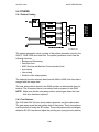
A133D595.wmf
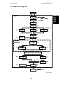
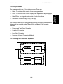
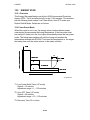
In this model, process control consists only of monitoring the toner density
(with a correction from the ID sensor) in order to control the toner
concentration and toner supply amount.
The machine controls the toner supply mechanism using readings from the
toner density sensor (TD sensor) and image density sensor (ID sensor).
Readings from the TD sensor are used to keep the toner concentration in the
developer at a constant level. However, the toner concentration on the image
on the drum varies due to variations in toner chargeability, which is
influenced by the environment and the status of the carrier, even if the toner
concentration is constant. Because of this, readings from the ID sensor are
used to change the toner concentration to keep the image density of the
reference pattern on the drum constant.
2-3
PROCESS CONTROL
22 March 1996
2.2 TONER DENSITY CONTROL
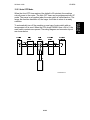
2.2.1 Overview
There are two modes for controlling toner supply: detect supply mode and
fixed supply mode.
The mode can be changed with SP2208-1. The factory setting is detect
supply mode.
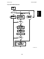
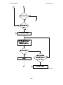
2.2.2 Detect Supply Mode
Overview
&RS\LQJ
,PDJH3L[HO&RXQW
'HWHFWVWKHDPRXQWRIWRQHU
WREHXVHG
97 GHWHFWLRQ
)X]]\&RQWURO
)DFWRUV
975()97
975()97
97 &XUUHQW97
973UHYLRXV97
↓
*$,1'HWHUPLQDWLRQ
7RQHU6XSSO\&/RQWLPH
FDOFXODWLRQ
1R
+DYHFRSLHVEHHQ
PDGHVLQFHWKHODVW
975()FKDQJH "
<HV
96396*'HWHFWLRQ
,'6HQVRU
)X]]\&RQWURO
)DFWRUV
975()97
96396*
↓
'HWHUPLQHVWKHUHTXLUHG
FKDQJHWR975()
∆
ZKLFKLV 975()
1HZ975()
∆
&XUUHQW975()
975()
A133D538.wmf
2-4
22 March 1996
PROCESS CONTROL
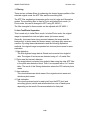
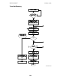
The flow chart on the previous page outlines the detect supply mode. Each
step is explained in more detail on the following pages.
Toner Density Sensor
7&9
7
6HQVRURXWSXW>9@ 7RQHUZHLJKW>ZW@
A133D594.wmf
Developer consists of carrier particles (ferrite) and toner particles (resin and
pigment). Inside the development unit, developer passes through a magnetic
field created by coils inside the toner density sensor. When the toner
concentration changes, the voltage output by the sensor changes accordingly.
The output from the sensor (VT) is checked every copy. The machine tries to
keep VT constant by varying the toner supply using a fuzzy logic process, as
shown in the flow chart on the previous page.
Toner Density Sensor Initial Setting
When new developer with the standard toner concentration (2.5% by weight,
21.25 g of toner in 850 g of developer) is installed, the TD sensor initial
setting must be done using SP mode 2801. This sets the sensor output to 2.5
± 0.1 V. This value will be used as the toner supply reference voltage (VTREF)
of the TD sensor.
2-5
Detailed
Descriptions
In detect supply mode, the machine varies toner supply for each copy based
on the amount of toner required to print the page (based on a black pixel
count for the page) and readings from the TD and ID sensors to maintain the
correct proportion of toner in the developer and to account for changes in
drum reflectivity over time.
PROCESS CONTROL
22 March 1996
Toner Density Measurement
Toner density in the developer is detected once every copy cycle. The sensor
output voltage (VT) during the detection cycle is compared with the toner
supply reference voltage (VTREF).
Toner Supply Clutch On Time Calculation
7
9
7'6HQVRU
75()97
9
)X]]\&RQWURO
*$,1
7RQHU6XSSO\&/RQ
75()97
9
7LPH
,PDJH3L[HO&RXQW
A133D540.wmf
- Fuzzy Control Process 1 To stabilize toner concentration, the toner supply amount (controlled by the
toner supply clutch on time) is determined by referring to VTREF and VT.
The toner supply amount is calculated every copy using the following factors.
Factor 1: VTREF - VT
Factor 2: VTREF - VT-1
• VTREF: TD sensor output at the latest VSP detection corrected for ID
sensor output (VSP/VSG); this is calculated every 200 copies (see
VTREF calibration for more details). For new developer, the TD sensor
initial setting is used.
• VT: Current TD sensor output data
• VT-1: Previous TD sensor output data
By referring to these factors, the machine recognizes the difference between
the current toner concentration and the target toner concentration. It then
determines the GAIN value for calculating the toner supply clutch on time.
- Image Pixel Count The CPU refers to the solid area ratio for the whole page informed from the
EX-IPU to improve the precision of the toner density change prediction.
The CPU converts the image data value of each pixel to the toner supply
amount. Therefore, the machine understands by how much the toner supply
amount will probably change.
2-6
22 March 1996
PROCESS CONTROL
- Toner Supply Clutch On Time Calculation -
mg
GAIN x Image pixel count x 0.7 ⁄cm2
Toner supply CL on time =
Toner supply rate (116 mg⁄s )
NOTE: The toner supply rate can be changed with SP2209. For example, if
the user commonly makes copies with a lot of black areas, reduce
the value stored in SP2209.
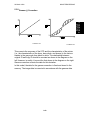
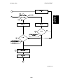
VTREF Calibration
- VSP and VSG Detection The ID sensor (below the drum cleaning section) detects the following
voltages.
• VSG: The ID sensor output when checking the drum surface.
• VSP: The ID sensor output when checking the VSP pattern.
In this way, the reflectivity of both the drum surface and the pattern on the
drum are checked. This compensates for any variations in the reflectivity of
the pattern on the drum or the reflectivity of the drum surface.
The VSP pattern is made on the drum by the charge corona unit and the laser
diode.
A133D541.wmf
VSP/VSG detection is performed every 200 copies to decide the new VTREF.
The value of the copy counter for the VSP/VSG detection is stored in the
NVRAM (Non-volatile RAM) on the SCU board. So, even if the machine is
switched off, the copy count starts from the number which was stored in the
NVRAM. In addition, as the diagram shows, the new VTREF will take effect
even if the 200th copy occurs in the middle of a copy run; however, the
overall cpm for this copy run will be lower because of the copy cycle required
to make the ID sensor pattern.
2-7
Detailed
Descriptions
The toner supply clutch on time is decided using value of the gain which was
calculated by the fuzzy control 1 procedure, the image pixel count value, the
possible amount of toner on the drum, and the toner supply rate. The
calculation is done using the following formula:
PROCESS CONTROL
22 March 1996
- New VTREF Determination Even if the toner concentration in the developer is kept constant by checking
the TD sensor, the toner potential (chargeability) and the image density
change with humidity and the amount of toner on the carrier.
Therefore, the ID sensor output is also used as one of the factors for deciding
the new VTREF which will be used for toner density control.
7'6HQVRU
97
975()97
96396*
∆975()
)X]]\&RQWURO
&XUUHQW975()
∆975()
1HZ975()
,'6HQVRU
A133D542.wmf
First of all, the CPU decides the adjustment that is required to the current
VTREF (∆VTREF) with the fuzzy control 2 procedure using the following factors.
• VTREF - VT
• VSP/VSG
Then, the CPU determines the new VTREF using the following formula.
New VTREF = VTREF + ∆VTREF
From this point, toner density control is done using the new VTREF.
If VTREF is either higher than 4.0 V or less than 0.5 V on more than 10
consecutive occasions, the GAIN value is fixed at 0.7 (see the equation at
the end of the "Toner Supply Clutch On Time Calculation" section). Then,
after finishing the copy job, SC390 will be generated.
2.2.3 Fixed Supply Mode
The machine supplies a fixed amount of toner every copy. The amount
depends on the setting of SP2208-2 (for users who normally make copies
with a lot of black areas, use a higher setting). Readings from the TD and ID
sensors are ignored.
Fixed supply mode should only be used as a temporary measure while
waiting for replacement parts, such as a TD sensor. The machine does not
fall back to fixed supply mode when there are sensor errors.
2-8
22 March 1996
PROCESS CONTROL
2.2.4 Toner Supply in Abnormal Sensor Conditions
Overview
The TD sensor is checked every copy. If the readings from the TD sensor
become abnormal during a copy job, the machine holds the GAIN factor
constant (GAIN is normally calculated from TD sensor readings) to allow
toner supply to vary with only pixel count for the rest of the copy job. Then at
the end of the copy job, an SC code is generated and the machine must be
repaired. There is no fallback to fixed supply mode in this model.
The ID sensor is checked every 200 copies. If readings become abnormal,
an SC code is generated and the machine must be repaired. If this happens
during a copy job, VTREF is not changed, the copy job is allowed to finish,
and then the SC code is generated.
Details of abnormal sensor detection follow below.
Abnormal TD Sensor Output (during normal operation and VTREF
determination)
When VT has been more than 4.0 V or less than 0.5 V on ten consecutive
occasions, the CPU fixes the value of the GAIN factor in the toner supply
clutch on time formula to 0.7. Then the toner is supplied in accordance with
the value of the image pixel count data. After finishing the copy job, SC390
will be generated.
Also, SC390 is generated when the difference between VT and VTREF has
been more than 0.6 V ten times.
Abnormal ID Sensor Output (during VSP/VSG measurement)
When VSP≥2.5V or VSG≤2.5V twice consecutively, SC350 will be generated.
At this time, VTREF remains at the previous value.
Also, SC350 is generated if VSG cannot be adjusted to 4 ± 0.2V during ID
sensor initialization (SP3001: this is done after installing a new drum or a new
ID sensor, or after cleaning the ID sensor).
2-9
Detailed
Descriptions
Under normal conditions, the machine uses detect supply mode, in which
toner supply is varied based on readings from the TD and ID sensors.
DRUM UNIT
22 March 1996
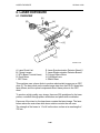
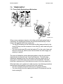
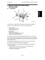
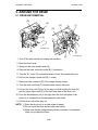
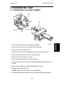
3. DRUM UNIT
3.1 OVERVIEW
6
7
1
5
4
3
2
A133D500.wmf
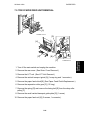
The drum unit consists of the components shown in the above illustration. An
organic photoconductor (OPC) drum (diameter: 100 mm) is used in this
model.
1. OPC Drum
5. Cleaning Blade
2. Pick-off Pawls
6. Quenching Lamp
3. ID Sensor
7. Charge Corona Unit
4. Cleaning Brush
2-10
22 March 1996
DRUM UNIT
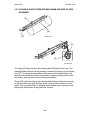
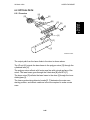
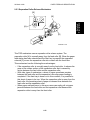
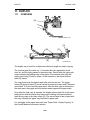
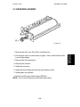
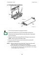
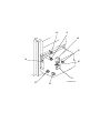
3.2 DRIVE MECHANISM
[D]
[C]
[B]
A133D501.wmf
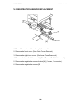
The drive from the main motor [A] is transmitted to the drum through a series
of gears, a timing belt, the drum drive pulley [B], and the drum shaft [C]. The
main motor has a drive controller, which outputs a motor lock signal when the
rotation speed is out of the specified range.
The fly-wheel [D] on the end of the drum shaft stabilizes the rotation speed
(this prevents banding from appearing and jitter on copies).
The drum rotation speed is 150 mm/s.
2-11
Detailed
Descriptions
[A]
DRUM UNIT
22 March 1996
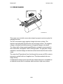
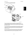
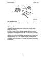
3.3 DRUM CHARGE
[B]
[A]
[C]
[D]
A133D502.wmf
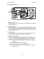
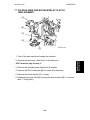
This copier uses a double corona wire (single loop type) scorotron system for
charging the drum.
The two corona wires apply negative charge to the drum surface. The
stainless steel grid plate [A] makes the corona charge uniform. The negative
voltage on this grid controls the amount of negative charge on the drum.
The charge high voltage supply board [B] gives a constant corona current to
the corona wires, and applies –890V to the grid plate. The grid plate voltage
maintains a constant charge on the drum surface even when the wire current
varies.
The ozone fan [C] provides a flow of air through the corona unit [D] in order to
prevent an uneven build up of negative ions. This helps maintain an even
image density.
A replacement charge corona unit with wire cleaner and motor is available as
an optional service part for machines which produce a high copy volume.
2-12
22 March 1996
DRUM UNIT
Detailed
Descriptions
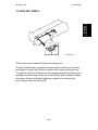
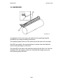
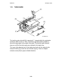
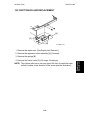
3.4 PICK-OFF PAWLS
[A]
A133D504.wmf
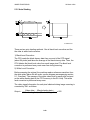
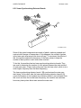
There are two pick-off pawls [A] under the cleaning unit.
The pick-off pawls help to separate the copy paper from the drum, and they
are always in contact with the drum surface under a weak spring pressure.
The position of the pick-off pawls can be changed manually to prevent drum
damage at an early stage caused by contact with the pick-off pawls. Change
the position if lines are already beginning to appear on the drum at the
pick-off pawl position at the first PM.
2-13
DRUM UNIT
22 March 1996
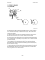
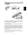
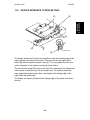
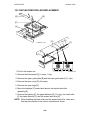
3.5 DRUM CLEANING
3.5.1 OVERVIEW
[C]
[B]
[A]
[D]
A133D505.wmf
6 mm
A113D513.wmf
The cleaning brush [A] and cleaning blade [B] remove any toner remaining
on the drum after the image is transferred to the paper. This model uses a
counter blade system.
To reduce the wear on the drum, the cleaning brush and the drum move in
the same direction at their point of contact, unlike previous models.
The main purpose of the cleaning brush is to improve the cleaning efficiency
of the cleaning blade, by spreading out any leftover toner on the drum before
it reaches the blade.
Toner scraped off by the cleaning blade will fall onto the cleaning brush,
which will then be scraped off by the brush flicker [C] to be carried away by
the toner collection coil [D].
To remove the toner and other particles that are accumulated at the edge of
the cleaning blade, the drum turns in reverse for about 6 mm at the end of
every copy job as shown in the illustration.
2-14
22 March 1996
DRUM UNIT
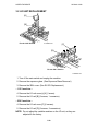
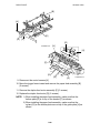
3.5.2 DRIVE MECHANISM
Detailed
Descriptions
[A]
[D]
[C]
[B]
A133D507.wmf
Drive from the main motor [A] is transmitted to the cleaning brush gear [B] via
a series of gears, a timing belt, and the joint gear [C]. The cleaning brush
gear then transmits the drive to the toner collection coil [D].
2-15
DRUM UNIT
22 March 1996
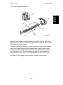
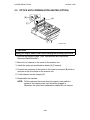
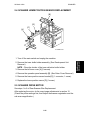
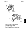
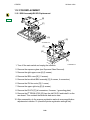
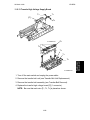
3.5.3 CLEANING BLADE PRESSURE MECHANISM AND SIDE-TO-SIDE
MOVEMENT
[A]
[B]
[C]
A133D598.wmf
[E]
[D]
A133D509.wmf
The spring [A] always pushes the cleaning blade [B] against the drum. The
cleaning blade pressure can be manually released by pushing up the release
lever [C]. To prevent cleaning blade deformation during transportation, the
release lever should be locked in the pressure release (upper) position with
the retainer pins that were removed during installation.
The pin [D] at the rear end of the cleaning blade holder touches the inner rim
of the sinusoidal cam gear [E] which gives a side-to-side movement to the
blade. This movement helps to disperse accumulated toner to prevent early
blade edge deterioration at any particular location.
2-16
22 March 1996
DRUM UNIT
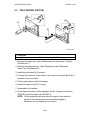
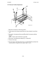
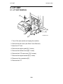
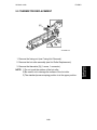
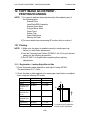
3.5.4 TONER COLLECTION MECHANISM
Detailed
Descriptions
[B]
[C]
[A]
A133D511.wmf
[F]
[E]
[D]
A133D510.wmf
The toner collected in the drum cleaning unit is carried into the toner
collection bottle [A] by the drum toner collection coil [B]. The toner collected
in the transfer belt unit is carried into the toner collection bottle by the transfer
belt collection coil [C].
The toner collection bottle is pressed against the cam gear [D] by a spring [E]
on the front side. The drive from the main motor drives the cam gear and
shakes the toner collection bottle from front to rear to make the level of the
collected toner even.
The toner overflow sensor [F] detects when the toner collection bottle is full.
After the toner overflow sensor is activated, 250 copies are allowed, then
copying is prohibited and a call service message appears on the LCD.
2-17
DRUM UNIT
22 March 1996
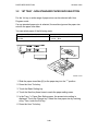
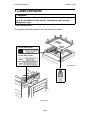
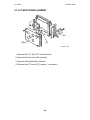
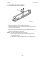
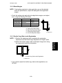
3.6 QUENCHING
[B]
[A]
A133D503.wmf
In preparation for the next copy cycle, light from the quenching lamp [A]
neutralizes any charge remaining on the drum.
The quenching lamp turns on at the same time as the main motor activates.
Red LEDs are used for the quenching lamp to reduce ultra-violet light that
would cause light fatigue on the drum.
The mylar [B] on the side of the quenching lamp stops the flow of air from the
cleaning unit to the charge corona unit, to prevent the charge corona unit
from becoming dirty with toner.
2-18
22 March 1996
SCANNING
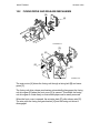
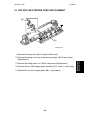
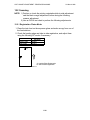
4. SCANNING
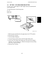
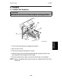
4.1 OVERVIEW
[B]
[E]
Detailed
Descriptions
[A]
[K]
[J]
[M]
[C]
[D]
[L]
A133D591.wmf
[E]
[I]
[F]
[G]
A133D508.wmf
[H]
An image of the original illuminated by the exposure lamp (a halogen lamp in
this model) [A] is reflected onto a CCD (charge coupled device) [B] via the
1st, 2nd, 3rd mirrors, green filter [C], and lens [D].
The 1st scanner [E] consists of the exposure lamp, main and sub reflectors
[F, G], and 1st mirror [H].
This model uses a halogen lamp for the exposure lamp, unlike the former
black/white digital copiers which use fluorescent lamps. This is because a
fairly fast cpm machine such as this one requires a greater light intensity than
slower models. The exposure lamp is energized by a dc supply to avoid
uneven light intensity as the 1st scanner moves in the sub scan direction.
The entire exposure lamp surface is frosted to ensure even exposure in the
main scan direction.
The green filter improves the reproduction of red areas in the original.
The light reflected by the main and sub reflectors is almost of equal intensity,
to reduce shadows on pasted originals.
2-19
SCANNING
22 March 1996
The thermoswitch [I] in the 1st scanner prevents overheating. It will turn off
the exposure lamp at around 140°C.
The optics fan motor [J] is located under the home position of the scanner
unit. It blows air into the optics cavity to prevent the exposure lamp and optics
cavity from overheating during copying. The hot air exits through the vents in
the upper cover.
The IPU fan motor [K] is located at the right side of the optics cavity under the
lens housing cover. This fan blows air directly on the EX-IPU board [L] to
prevent overheating.
An optics anticondensation heater [M] is available as optional equipment,
which can be installed on the left side of the optical base plate. It turns on
when the main switch is off.
2-20
22 March 1996
SCANNING
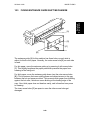
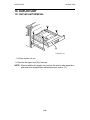
4.2 SCANNER DRIVE
[A]
[E]
Detailed
Descriptions
[F]
[B]
[D]
[C]
A133D592.wmf
A five-phase stepper motor is used to drive the scanner. The 1st and 2nd
scanners [A,B] are driven by this scanner drive motor [C] through the timing
belt [D], scanner drive pulley [E], scanner drive shaft [F], and two scanner
wires.
In full size mode, the 1st scanner speed is 200 mm/s during scanning. The
2nd scanner speed is half that of the 1st scanner.
In reduction or enlargement mode, the scanning speed depends on the
magnification ratio (M: 0.25 to 4.00) as follows: 200/M mm/s. The returning
speed is always the same, whether in full size or magnification mode. The
image length change in the sub scan direction is done by changing the
scanner speed and in the main scan direction it is done by image processing
on the EX-IPU board.
The scanner drive board controls and operates the scanner motor.
Magnification in the sub-scan direction can be adjusted by changing the
scanner drive motor speed using SP4008.
2-21
SCANNING
22 March 1996
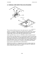
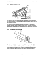
4.3 ORIGINAL SIZE DETECTION IN PLATEN MODE
[E]
A133D537.wmf
[D]
[C]
[B]
[A]
A133D539.wmf
There are three reflective sensors in the optics cavity for original size
detection. The Original Width Sensor [A] detects the original width, and the
Original Length Sensor-1 [B] and Original Length Sensor-2 [C] detect the
original length. These are the APS (Auto Paper Select) sensors.
Inside each APS sensor, there is an LED [D] and either three photoelectric
devices [E] (for the width sensor) or one photoelectric device (for each length
sensor). In the width sensor, the light generated by the LED is broken up into
three beams and each beam scans a different point of the exposure glass (in
each length sensor, there is only one beam). If the original or platen cover is
present over the scanning point, the beam is reflected and each reflected
beam exposes a photoelectric device and activates it.
While the main switch is on, these sensors are active and the original size
data is always sent to the main CPU. However, the main CPU checks the
data only when the platen cover is opened.
2-22
22 March 1996
SCANNING
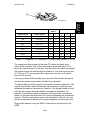
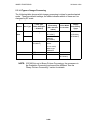
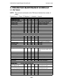
[A]
Original Size
Length
Sensor
Detailed
Descriptions
A133D536.wmf
Width Sensor
A4/A3 version
LT/DLT version
1
2
3
4
5
A3
11" x 17"
O
O
O
O
O
B4
10" x 14"
O
O
O
O
X
F4
81/2" x 14" (8" x 13")
O
O
O
X
X
A4–L
81/2" x 11"
X
O
O
X
X
B5–L
—
X
O
X
X
X
A5–L
51/2" x 81/2"
X
X
X
X
X
A4–S
11" x 81/2"
X
X
O
O
O
B5–S
—
X
X
O
O
X
A5–S
81/2" x 51/2"
X
X
O
X
X
Note: –L= Lengthwise, –S = Sideways, O = High (Paper Present), X = Low
The original size data is taken by the main CPU when the platen cover
sensor [A] is activated. This is when the platen is positioned about 15 cm
above the exposure glass. At this time, only the sensor(s) located underneath
the original receive the reflected light and switch on. The other sensor(s) are
off. The main CPU can recognize the original size from the on/off signals
from the five sensors.
If the copy is made with the platen open, the main CPU decides the original
size from the sensor outputs when the Start key is pressed.
The above table shows the outputs of the sensors for each original size. This
original size detection method eliminates the necessity for a pre-scan and
increases the machine’s productivity. However, if the by-pass feeder is used,
note that the machine assumes that the copy paper is lengthwise. For
example, if A4 sideways paper is placed on the by-pass tray, the machine
thinks it is A3 paper and scans the full A3 area, disregarding the original size
sensors. This can cause excess toner to be transferred to the belt, so users
should be instructed to always set the paper lengthwise on the by-pass tray.
Original size detection using the ARDF is described in the manual for the
ARDF.
2-23
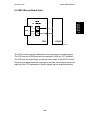
IMAGE PROCESSING
22 March 1996
5. IMAGE PROCESSING
5.1 OVERVIEW
White Plate
A133D543.wmf
The CCD generates an analog video signal. The SBU (Sensor Board Unit)
then sends the analog video signal to the EX-IPU (Extended Image
Processing Unit) board.
The EX-IPU board can be divided into three image processing blocks: VPU,
IPU, and laser diode controller.
• VPU: A/D conversion, signal composition, and auto shading.
• IPU: γ correction, auto text/photo separation, filtering, magnification
adjustment, image creation, and dither processing.
• LD controller: Printer γ correction and the LD print timing control.
Finally, the EX-IPU board sends 8-bit video data to the LD drive board at the
correct time.
2-24
22 March 1996
IMAGE PROCESSING
5.2 SBU (Sensor Board Unit)
&&'
Detailed
Descriptions
6LJQDO
$PSOLILFDWLRQ
2GG
(YHQ
6%8
(;,38
A133D544.wmf
The CCD converts the light reflected from the original into an analog signal.
The CCD line has 5,000 pixels and the resolution is 400 dpi (15.7 lines/mm).
The CCD has two output lines, for odd and even pixels, to the EX-IPU board.
Since the processing speed for one pixel is very fast, odd and even pixels are
read from the CCD separately so that the signals can be amplified properly.
2-25
IMAGE PROCESSING
22 March 1996
5.3 EX-IPU (Extended Image Processing Unit)
5.3.1 Overview
&&'GULYHFORFN
(;,38
$*&
6%8
2GG
$QDORJ
(YHQ
3URFHVV
,&
*$
$'
±
$XWRVKDGLQJ
±
&&'GULYHFORFN
*$
%&8
&38
±
07)
±
6PRRWKLQJ
±
$XWR7H[W3KRWR
±
0DJQLILFDWLRQ
*$
+''
*$
/''5
/'&RQWUROOHU
±
*UD\VFDOHSURFHVVLQJ
±
%LQDU\SLFWXUHSURFHVVLQJ
*$
±
(UURUGLIIXVLRQ
&RPSUHVVLRQ
±
'LWKHULQJ
'HFRPSUHVVLRQ
±
γFRUUHFWLRQ
±
3DWWHUQJHQHUDWLRQ
A133D545.wmf
The EX-IPU uses seven LSIs and a hard disk to process the video data.
These LSIs have the following functions.
1. Analog Process IC
Signal amplification and signal composition.
2. A/D Converter
Converts analog video signals to 8-bit digital video signals.
3. GA1 (Gate Array 1)
Generates the CCD drive clock and does auto shading
4. GA3 (Gate Array 3)
MTF, smoothing, auto text/photo separation, and magnification
5. GA4 (Also called the GASHITE IC)
Grayscale processing, binary picture processing, error diffusion, dithering,
γ correction, and pattern generation.
6. GA5 (Also called the GAFBTC IC)
Image data compression and decompression.
7. GA6 (Also called the GAABS IC)
Image data interface between GA4 and HDD.
8. Hard Disk Drive
Stores the compressed image data. Also holds user stamp data.
2-26
22 March 1996
IMAGE PROCESSING
5.3.2 Image Processing Path
(;,38
&RPSRVLWLRQ
$QDORJ3URFHVVLQJ,&
,QFOXGHV$'6LILWZDV
$PSOLILFDWLRQ
VHOHFWHG
$'
$XWRVKDGLQJ
6PRRWKLQJ
3DWWHUQ
*$
*HQHUDWRU
7H[W3KRWR0RGH
7H[W0RGH
3KRWR0RGH
*$
*$
07)&RUUHFWLRQ
*$
6HOHFWRU
*$
0HUJH
*$
$XWR7H[W3KRWR
6HSDUDWLRQ
*$
0HPRU\%ORFN
,PDJH5RWDWLRQ
LQFOXGLQJ+''
$GMXVW,PDJH
*$
*$
%LQDU\3LFWXUH
*UD\VFDOH
3URFHVVLQJ
3URFHVVLQJ
/DVHU'LRGH3XOVH3RVLWLRQLQJ
*$
(UURU'LIIXVLRQ
3DWWHUQ*HQHUDWRU
*$
'LWKHULQJ
0HUJH
/''5
*$
/LQH:LGWK
6HOHFWRU
*$
*$
&RUUHFWLRQ
*$
*$
/DVHU'LRGH3RZHU
0RGXODWLRQ
A133D546.wmf
2-27
Detailed
Descriptions
6%8
IMAGE PROCESSING
22 March 1996
5.3.3 Analog Processing
'$
2GG
=&
'$
'$
$*&
=&
)URP
6%8
(YHQ
=&
9LQ
$'
0XOWLSOH[HU
*$
9UHI
3+
=&=HUR&ODPS
6(/
3+3HDN+ROG
'$'$&RQYHUWHU
'$
$*&$XWRPDWLF*DLQ
195$0
&RQWURO&LUFXLW
A133D547.wmf
1) Signal Composition
Analog signals for odd and even pixels from the SBU board are merged
by a switching device.
2) Signal Amplification
The analog signal is amplified by operational amplifiers in the AGC circuit.
The maximum gains of the operational amplifiers are controlled by the
CPU on the EX-IPU board by monitoring the feedback signals (Auto Gain
Control signal) from GA1.
3) A/D Conversion
The amplified analog signals are converted to 8-bit digital signals. This
will give a value for each pixel on a scale of 256 grades.
4) Feedback - D/A Conversion
The CPU monitors the feedback signals from the shading circuit in the
GA1 and the NV RAM, then calculates correction factors. These digital
values are converted to analog signals and fed back to each circuit.
• D/A1: Adjusts the black level references for even pixels to match the
even pixels.
• D/A2: Adjusts the gain curve of the amplifier.
• D/A3: Adjusts the absolute value of the black level.
• D/A4: Adjusts the reference value of the white level when scanning
the white plate.
2-28
22 March 1996
IMAGE PROCESSING
Detailed
Descriptions
5.3.4 Auto Image Density (ADS)
[A]
A133D506.wmf
'$
2GG
=&
'$
'$
$*&
=&
)URP
6%8
(YHQ
=&
9LQ
$'
0XOWLSOH[HU
*$
9UHI
3+
=&=HUR&ODPS
6(/
3+3HDN+ROG
'$
'$'$&RQYHUWHU
$*&$XWRPDWLF*DLQ
195$0
&RQWURO&LUFXLW
A133D547.wmf
[B]
This mode prevents the background of an original from appearing on copies.
The copier scans the auto image density detection area [A] as shown in the
diagram. The CPU detects the peak white level every scan line in the area
using the P/H (Peak Hold) circuit [B]. Then the peak white data is sent to the
A/D converter to be the reference value. The video signal is converted to
digital data using the peak white data. So, for example, when an original with
a gray background is scanned, the density of the gray area is the peak white
level density. So, the original background does not appear on copies.
Unlike with analog copiers, the user can select a manual image density when
selecting auto image density mode, and the machine will use both settings
when processing the original. This is useful when making copies of an
original that has light image density with background; ADS removes the
background, and if the user selected a dark manual image density setting,
the image will be brought out more clearly in the copy.
2-29
IMAGE PROCESSING
22 March 1996
5.3.5 Auto Shading
A133D548.wmf
There are two auto shading methods. One is black level correction and the
the other is white level correction.
1) Black Level Correction
The CPU reads the black dummy data from one end of the CCD signal
(about 64 pixels) and takes the average of the black dummy data. Then, the
CPU deletes the black level value from each image pixel. The black level
correction is performed every main scan line during scanning.
2) White Level Correction
Before scanning the original, the machine reads a reference waveform from
the white plate (below the left scale; see the diagram accompanying section
5-1: Overview). The average of the white video level for each pixel is stored
as the white shading data in the FIFO memory in the GA1 chip. This white
level correction is performed every scan.
The video signal information for each pixel obtained during image scanning is
corrected by GA1 as follows.
Output =
(Video data ) − (Black shading data )
x 255
(White shading data) − (Black shading data)
2-30
22 March 1996
IMAGE PROCESSING
5.3.6 Original Modes
•
Letter: For originals that consist of line drawings and text
•
Photo: For originals that consist of grayscale images such as photographs
•
Letter/Photo: For originals that consist of both of the above
•
Generation: When making a copy of a copy
The machine uses various filtering and processing techniques to enhance the
data to suit the selected mode. These will be explained in the following
sections:
•
Filtering and Text/Photo Separation
•
Gradation Processing
•
Line Width Correction
•
Summary of Image Processing Methods
5.3.7 Filtering and Text/Photo Separation
*$
)LOWHU
07)&RUUHFWLRQ
)LQDO(YDOXDWLRQ
6HOHFWRU
6PRRWKLQJ
$XWR7H[W3KRWR6HSDUDWLRQ
(GJH'HWHFWLRQ
$UHD(YDOXDWLRQ
'RW6FUHHQ
'HWHFWLRQ
A133D549.wmf
2-31
Detailed
Descriptions
The user can select one of four original modes. These are:
IMAGE PROCESSING
22 March 1996
1. Filtering
There are two software filters for enhancing the desired image qualities of the
selected original mode: the MTF filter and the smoothing filter.
The MTF filter emphasizes sharpness and is used in Letter and Generation
modes. The smoothing filter is used in Photo and Letter/Photo mode. (In
Photo mode, this can be changed to MTF using SP 4904-3.)
The filter strengths for these modes can be adjusted with SP 4903-1.
2. Auto Text/Photo Separation
This is used only in Letter/Photo mode. In Letter/Photo mode, the original
image is separated into text and photo areas (dot screen areas).
Generally, text areas have strong contrast between the image and the
background. In photo areas (dot screen areas), mid-range gray areas are
common. By using these characteristics and the following separation
methods, the original image is separated into text and photo areas for area
evaluation.
1. Edge detection
The 8-bit digitized image data is filtered and converted into single-bit
data. The edges of text areas are detected using a 3 x 3 matrix filter.
2. Photo area (dot screen) detection
The image data is converted into single-bit data using the other MTF filter
in the photo area detection block. Then it is compared with a 5 x 5 matrix
table. The result of this filtering determines where the CPU detects photo
areas.
3. Area evaluation
This circuit determines which areas of the original are text areas and
which are photo areas.
4. Final evaluation
This circuit receives inputs for each pixel from the MTF (text) and
smoothing (photo) circuits and selects data from one of these inputs
depending on the result of the area evaluation for that pixel.
2-32
22 March 1996
IMAGE PROCESSING
Detailed
Descriptions
5.3.8 Gamma (γ) Correction
A133D551.wmf
A133D552.wmf
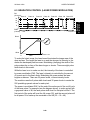
This corrects the response of the CCD and the characteristics of the printer
(i.e., the characteristics of the drum, laser diode, and lenses) to the various
shades in the gray scale from black to white. The relationship between
original ID and copy ID should be constant as shown in the diagram on the
left. However, in reality, it is more like that shown in the diagram on the right.
Gamma correction corrects the data for this deviation.
In this model, the data for the gamma correction is fixed and stored in the
memory. The image data is corrected in accordance with the gamma data.
2-33
IMAGE PROCESSING
22 March 1996
5.3.9 Main Scan Magnification
A133D550.wmf
Reduction and enlargement in the sub scan direction are done by changing
the scanner speed. However, reduction and enlargement in the main scan
direction are handled by the GA3 chip on the EX-IPU board.
Scanning and laser writing are done at a fixed pitch (the CCD elements
cannot be squeezed or expanded). So, to reduce or enlarge an image,
imaginary points are calculated that would correspond to a physical
enlargement or reduction of the image. The correct image density is then
calculated for each of the imaginary points based on the image data of the
nearest four true points. The calculated image data then becomes the new
(reduced or enlarged) image data.
Main scan magnification can be disabled with SP 4903-5 to test the GA3 IC.
2-34
22 March 1996
IMAGE PROCESSING
5.3.10 Memory Block
&38%XV
),)2
;%DQN
*$
*$
6&6,
+''
&RQWUROOHU
<%DQN
*$
A133D596.wmf
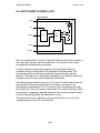
The memory block consists of the GA5 and GA6 ICs, the SCSI controller,
and the hard disk drive. The functions of each device are as follows.
GA5:
Compressing the 8-bit image data
Image rotation
Image data transfer to the FIFO memory, DRAM,
and the GA6
GA6:
Image data handling to/from the hard disk drive
FIFO memory:
Line buffer memory for image compression
(5k x 8 bits total 14 pcs)
DRAM:
Page memory for image compression (12MB). This
can store enough data for an A3 size page.
Hard Disk Drive
Stores the compressed image data (1 GB).
All scanned data goes through this memory block. This memory block
functions like a page memory, in which the scanned image data is held
before printing. As a result, many copies can be made with one scan, and
various functions can be performed on the stored image data, including the
following.
• Rotate Image
• Combine Mode
• Image Repeat
• Overlay/Merge
• Sort, Rotate Sort, and Stack
2-35
Detailed
Descriptions
'5$0
IMAGE PROCESSING
22 March 1996
5.3.11 Image Compression and Decompression
3L[HO
EORFN
SL[HOV
6XE6FDQ'LUHFWLRQ
0DLQ6FDQ'LUHFWLRQ
2Q
Q
Q
Q
Q
– Image Data Memory Mapping –
'HJUHHV
'HJUHHV
'HJUHHV
'HJUHHV
– Image Rotation –
A133D597.wmf
FIFO Memory
The image data from the GA4 IC first goes to the FIFO block. This block
consists of total 14 FIFO memories (7 for the input data, the others for the
output data) because the image compression is done using four scan lines at
the same time to improve the image compression speed.
GA5
The image data then goes to the GA5 IC, where the image data for a whole
page is divided into many blocks (the block size is 4 x 4 pixels) as shown
above left. Then, each block is compressed (the compression ratio is 2/3)
and sent to GA6 through the DRAM.
For printing, the compressed data block from the GA6 IC goes back to the
GA5 IC through the DRAM. This IC assigns these blocks to the proper
positions for printing, then the data blocks are decompressed.
In the image rotation mode, each compressed data block from the GA6 IC is
rotated into the correct orientation and mapped into the proper position, then
the blocks are decompressed.
When grayscale processing mode is selected (this is the default), the input
and output image data are handled as 8-bit signals. When binary picture
processing mode is selected (using SP4904-4), the input signal is handled as
an 8-bit signal but the output signal is handled as a single-bit signal.
2-36
22 March 1996
IMAGE PROCESSING
Gradation processing is done after the data is retrieved from the hard disk.
There are two types of gradation processing:
• Grayscale processing: this has 256 output levels for each pixel, and is
used to get the best reproduction of grayscales
• Binary picture processing: this has only two output levels (black and
white)
The default gradation processing mode is grayscale processing. This default
can be changed using SP4904-4.
In some original modes, the gradation processing method in use can be
enhanced with a matrix processing technique (error diffusion or dithering).
For a summary of the types of processing selected by the machine for each
original mode, see section 5.3.14 "Summary of Image Processing Methods".
1. Grayscale Processing
- 1 x 1 and 2 x 1 dot processing -
A133D553.wmf
Each pixel has a video signal level between 0 and 255.
In this model, there two types of grayscale processing: 1 x 1 dot processing
and 2 x 1 dot processing.
1 x 1 dot processing just takes the video signal level for each pixel as it
comes.
In 2 x 1 dot processing, the levels of two adjacent dots are averaged, and the
video signal levels for both pixels are changed to this average value.
Using the 1 x 1 dot mode, the image will be became more sharp in focus than
using 2 x 1 dot mode.
2-37
Detailed
Descriptions
5.3.12 Gradation Processing
IMAGE PROCESSING
22 March 1996
The default modes for each original mode are as follows:
Letter Mode, Generation Mode: 1 x 1
Photo Mode: 1 x 1 with a 6 x 6 dither matrix (the dither matrix type can be
changed with SP mode 4904-2)
Letter/Photo Mode:
•
Text areas: 1 x 1 (this can be changed with SP mode 4904-7)
•
Photo areas: 2 x 1 with error diffusion (this can be changed with SP mode
4904-8)
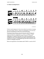
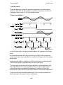
- Pulse Width Modulation This machine uses a form of pulse width modulation to generate the
grayscales and photo area reproduction effects.
In this machine, pulse width modulation consists of the following processes:
•
Laser diode pulse positioning
•
Laser diode power modulation
Laser diode power modulation is done by the laser diode drive board (LDDR),
and will be explained in the Laser Exposure section. Briefly, the width of the
laser pulse for a pixel will depend on the output level (from 0 to 255) required
for the pixel.
This section of the manual explains how laser diode pulse positioning is done.
A133D588.wmf
2-38
a133d589.wmf
22 March 1996
IMAGE PROCESSING
For each pixel, the location of the active (laser on) part can be either at the
left side of the laser drive signal for the pixel, at the center, or at the right
side. The diagram on the right (at the bottom of the previous page) shows
this for two adjacent pixels with equal laser signal pulse widths.
There is also a mode known as "concentrated", in which the left hand pixel of
an adjacent pair is printed with the active part on the right, and the right hand
pixel has the active part on the left. The effects of this mode are shown below.
A133D590.wmf
In 1 x 1 dot processing, the machine determines which type of pulse
positioning to use for adjacent pixels; the position of the active part of the
laser signal depends on the values of the adjacent pixels. In the example
shown above, the machine is printing a thin diagonal line. For the pixels in
this thin line, "concentrated" mode is used; the active part for the pixel on the
left is moved over to the right. Otherwise, the machine would print two thin
diagonal lines on the paper.
In 2 x 1 dot mode, the center mode is used. In this mode, the dots are always
a small distance apart, which leads to a better grayscale effect.
Pulse positioning can be switched on or off with SP4904-1.
• If pulse positioning is disabled, the active part of the laser signal is always
at the center of the pixel.
• If pulse pulse positioning is enabled, the type that is used (left, center,
right, concentrated) is determined automatically for each adjacent pair of
pixels (if 1 x 1 mode is used), or center mode (if 2 x 1 mode is used).
2-39
Detailed
Descriptions
The width of the laser pulse for each pixel has 8 settings (see the diagram on
the left at the bottom of the previous page).
IMAGE PROCESSING
22 March 1996
- Error Diffusion This can only be used in Letter/Photo mode.
The error diffusion process reduces the difference in contrast between light
and dark areas of a halftone image. Each pixel is corrected using the
difference between it and the surrounding pixels. The corrected pixels are
then compared with a error diffusion matrix table. This matrix table cannot be
selected.
1) Grayscale processing mode
In 1 x 1 dot processing mode, the output image signal level has 9 levels (from
white to black).
In 2 x 1 dot processing mode, the output image signal level has 17 levels.
2) Binary processing mode
The output image signal level has just 2 levels (white/black).
- Dither Processing This can only be used in Photo mode.
In dither processing, each pixel is compared with a pixel in a dither matrix
table, and in this machine, the result is an 8-bit value (from 0 to 255). There
are four dither matrixes that can be selected from to optimize image quality.
The matrix that is used depends on the setting of SP 4904-2.
• If 6 x 6 is selected (suitable for most documents), the processing mode
that is used (binary picture or gradation) depends on the setting of SP
4904-4.
• If 6 x 6 (new) is selected, the processing mode that is used also depends
on the setting of SP 4904-4. However, the gamma curve is different from
the one used in the above 6 x 6 mode, to improve reproduction of faint
originals.
• 8 x 8 can only be used if 4904-4 is set to "binary". Also, if 4904-4 is set to
"binary", the matrix is always 8 x 8, regardless of the setting of SP4904-2.
• 4 x 4 leads to a sharper image.
2-40
22 March 1996
IMAGE PROCESSING
2. Binary Picture Processing
If binary picture processing is enabled, pulse positioning (left, center, right,
concentrated) depends on the setting of SP2905.
In addition, note the following.
•
Photo Mode: A dither matrix will be used. The matrix is always 8 x 8
regardless of the setting of SP 4904-2.
•
Letter/Photo Mode: Error diffusion will be used.
5.3.13 Line Width Correction
This function is effective only in the generation copy mode.
Usually, when making a copy of an original which was made on a copier, the
line will bulge in the main scan direction as a result of the negative/positive
development system that is used in this model. So, pixels on edges between
black and white areas are compared with adjacent pixels, and if the pixel is
on a line, the line thickness will be reduced.
Also, in this model, lines can be thickened using a similar process to the
above.
The line width correction type can be selected with SP4904-6.
2-41
Detailed
Descriptions
Each video signal level is converted from 8-bit to 1-bit (black and white image
data) in accordance with a threshold level. The threshold level can be
adjusted with SP4904-12.
IMAGE PROCESSING
22 March 1996
5.3.14 Types of Image Processing
The following table shows which image processing is done for each selected
mode. These are default settings; the table indicates which of these can be
changed by SP mode.
Mode
Letter/
Photo
Area Type
Text Area
Filter Type
(Filter Strengths:
SP 4903-1)
Smoothing
Photo Area
Gradation
Processing
(See the Note
below)
1 x 1dot
(SP4904-7)
2 x 1dot, Error
diffusion
(SP4904-8)
1 x 1 dot
Dither
(6 x 6 matrix)
Matrix type:
SP4904-2
Photo
Smoothing
(SP4904-3)
Letter
MTF
1 x 1 dot
Generation
MTF
1 x 1 dot
Line Width
Correction
–
Image
Processing
Type
Grayscale
Processing
(SP4904-4)
–
–
Enabled
(SP4904-6)
NOTE: If SP4904 is set to Binary Picture Processing, the processes in
the Gradation Processing column will be different. See the
"Binary Picture Processing" section for details.
2-42
22 March 1996
IMAGE PROCESSING
5.4 OTHERS
5.4.1 Pattern Printing
&RPPDQG
7LPLQJ
&RQWURO
%DFNJURXQG
1XPEHULQJ
5$0
'DWH+RXU
60&/LVWV
6(/
520
'DWD
$XWR6WDPS
8VHU6WDPS
+''
5HJLVWHU
6WDPS
'DWD
3DWWHUQ*HQHUDWLRQ
A133D555.wmf
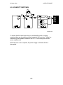
The pattern generation circuit consists of the pattern generation circuit in the
GA4 IC, RAM, ROM and Hard Disk. The pattern generation circuit has the
following functions.
• Background Numbering
• Date and Hour
• SMC (Service and Machine Communication) lists
• Auto stamp
• User stamp
• Rotation of the stamp pattern
The selected function retrieves data from the RAM or ROM, then this data is
merged with the image data.
The user stamp data is stored in the RAM and also in the hard disk drive for
backup. This is because there is no battery back-up system for the RAM.
NOTE: Make sure that the user stamp data is stored again when the hard
disk drive has been replaced.
5.4.2 Test Patterns
The GA3 and GA4 ICs have a test pattern generator and test pattern data.
The gate array sends the test pattern data to the printer. These test patterns
can be printed out using the SP modes. These test patterns help investigate
defective EX-IPU boards and adjust the printing area (using the trim pattern).
2-43
Detailed
Descriptions
'DWD
LASER EXPOSURE
22 March 1996
6. LASER EXPOSURE
6.1 OVERVIEW
[H]
[G]
[A]
[B]
[C]
[D]
[E]
[J]
[F]
[I]
A133D613.wmf
A: Laser Diode Unit
B: F-theta Lenses
C: BTL (Barrel Toroidal Lens)
D: Drum Mirror
I: OPC Drum
E: Laser Synchronization Detector Board-2
F: Laser Synchronization Detector Board-1
G: Polygon Mirror Motor
H: Cylindrical Lens
J: Shield Glass
This machine uses a laser diode to produce electrostatic images on an OPC
drum [I]. The laser diode unit converts image data from the EX-IPU board into
laser pulses, and the optical components direct these pulses to the OPC
drum.
To produce a high quality copy image, there are 256 gradations for the laser
pulses, controlled through power modulation and pulse width modulation.
Exposure of the drum by the laser beam creates the latent image. The laser
beam makes the main scan while drum rotation controls the sub scan.
The strength of the beam is 1.3 mW on the drum surface at a wavelength of
780 nm.
2-44
22 March 1996
LASER EXPOSURE
6.2 OPTICAL PATH
[H]
[G]
[A]
[B]
[C]
[D]
[E]
[J]
[F]
[I]
A133D613-2.wmf
The output path from the laser diode to the drum is shown above.
The LD unit [A] outputs the laser beam to the polygon mirror [G] through the
cylindrical lens [H].
The polygon mirror reflects a full main scan line with a single surface of the
mirror. The laser beam goes through the f-theta lens [B] and BTL [C].
The drum mirror [D] reflects the laser beam to the drum [I] through the toner
shield glass [J].
The laser synchronizing detector boards [E, F] determine the main scan
starting position, and detect variations in the time required to make a main
scan.
2-45
Detailed
Descriptions
6.2.1 Overview
LASER EXPOSURE
22 March 1996
[C]
[A]
[B]
A133D614.wmf
6.2.2 Cylindrical Lens
The laser beam is focused by the cylindrical lens [A], and sent to the polygon
mirror.
6.2.3 Polygon Mirror
The polygon mirror assembly consists of the polygon motor [B] and the
polygon mirror itself [C].
As the mirror rotates, it reflects the laser beam across the drum, via the
f-theta lens, BTL, and drum mirror. One main scan line is made by the beam
reflected from one face of the polygon mirror.
The mirror is precisely ground to enable high reflectivity and to prevent pixel
misalignment on the drum in both the main scan and sub scan directions.
The polygon mirror motor rotates at 31,496 rpm. One rotation corresponds to
six main scans.
2-46
22 March 1996
LASER EXPOSURE
6.2.4 F-theta Lenses and the BTL
Detailed
Descriptions
Wide spaced
Narrow spaced
[B]
[A]
Evenly
spaced
pixels
A133D615.img
The angles between pixels are equal. However, if the beam were to go
directly to the drum as shown in the upper illustration, the spacing between
pixels would differ with the angle of the beam. The pixels near the end of the
drum would be further apart than those near the middle of the drum. The
pixels would also be slightly thicker toward the ends of the drum than in the
middle.
The f-theta lenses [A] and BTL [B] correct for this by deflecting the beam
slightly inward to ensure uniform picture element spacing and diameter. The
f-theta lenses and BTL also correct for irregularities in the polygon mirror
face, focusing irregular beams onto the correct part of the drum.
2-47
LASER EXPOSURE
22 March 1996
6.2.5 Laser Synchronizing Detector Boards
[A]
[B]
A133D613-3.wmf
Some of the optical components are made of plastic, and may expand and
contract with changes of temperature. If this happens, the number of pulses
in the laser main scan across the drum will vary. To counteract the effects of
this, the machine adjusts the frequency of the laser pulses to keep the
number of laser pulses in each main scan constant.
To do this, the machine has two laser synchronizing detector boards. They
are used to determine the number of clock pulses between the start and end
of each main scan. (These clock pulses are from the base clock, which is at a
much higher frequency than the laser frequency.)
The laser synchronizing detector board-1 [B] synchronizes the main scan
start timing. At the other side, the laser synchronizing detector board-2 [A]
counts the number of clock pulses since detector board-1 was activated; from
this count and from the current laser frequency, the machine can calculate
how many laser pulses there were across the main scan.
2-48
22 March 1996
LASER EXPOSURE
6.3 GRADATION CONTROL (LASER POWER MODULATION)
PM
(32 levels)
Data: 0
Data: 16
Data: 32
Data: 48
Data: 64
2
2
Data: 136 Data: 255
24
16
8
1
8 1
PWM
(8 levels) 1 dot
1
5
8
A133d616.wmf
Black
White
0
Data
255
A133D617.wmf
To make the latent image, the laser beam illuminates the image area of the
drum surface. The longer the laser is on and the stronger its intensity is, the
darker the developed pixel becomes. Modulating (changing) the width of the
pulse makes the on time of the laser longer or shorter. There are eight pulse
width levels in this model.
While the laser is on to make one dot, the intensity of the laser is controlled
by power modulation (PM). The laser’s intensity is controlled by the amount
of current sent to the laser diode. Modulating the power makes the laser
brighter or dimmer. There are 32 power levels, or laser intensity levels.
The machine uses the 8 pulse width levels and 32 power levels to create the
256 possible grayscale values for each pixel.
The power is modulated ONLY at the end of the active part of the on/off cycle
of the laser pulse. For example (see the diagram above), to make a pixel with
a grayscale value of 48, the laser pulse width level for that pixel will be 2. The
first period of the pulse will be at the full power (32), and the second pulse will
be at power 16 to make up the remainder of the 48 (32 + 16 = 48).
2-49
Detailed
Descriptions
32
LASER EXPOSURE
22 March 1996
6.4 AUTO POWER CONTROL (APC)
LD Drive Board
PD
LD5 V
LD
+5 V
VIDEO
IC2
IC1
/9/
LEVEL
LD OFF
A133D618.wmf
Even if a constant electric current is applied to the laser diode, the intensity of
the output light changes with the temperature. The intensity of the output
decreases as the temperature increases.
In order to keep the output level constant, the output light intensity is
monitored through a photodiode (PD) enclosed in the laser diode. The
photodiode passes an electrical current that is proportional to the light
intensity. The output is not affected by temperature, so it faithfully reflects the
changes in the LD output, without adding anything itself.
Just after the main switch is turned on, IC2 on the LD drive board excites the
laser diode at full power (power level 32) and stores the output of the
photodiode as a reference in IC2. IC2 monitors the current passing through
the photodiode. Then it increases or decreases the current to the laser diode
as necessary, comparing it with the reference level. Such auto power control
is done during printing while the laser diode is active.
The laser power level is adjusted on the production line. Do not touch the
variable resistors on the LD unit in the field.
2-50
22 March 1996
LASER EXPOSURE
6.5 LD SAFETY SWITCHES
Detailed
Descriptions
[A]
A133D620.wmf
To ensure that the laser beam does not accidentally switch on during
servicing, there are two safety switches located at the front door. These two
switches [A] are installed in series on the LD 5 V line coming from the dc
power supply board.
When the front cover is opened, the power supply to the laser diode is
interrupted.
2-51
DEVELOPMENT
22 March 1996
7. DEVELOPMENT
7.1
OVERVIEW
[E]
[C]
[B]
[G]
[F]
[A]
Unit rotation
[D]
Developer flow
A133D512.wmf
This copier uses a double roller development (DRD) system.
The diameters of the two development rollers are different from each other
because the position where the development unit contacts the drum is
located slightly higher than in other models.
The DRD system differs from the single roller development system in that (1)
the diameter of each development roller is narrower (narrower development
nip against the drum), (2) each develops the image (the image is developed
twice), and (3) the relative speed of each development roller against the drum
is reduced. As a result, the image quality of black cross points and the trailing
edges of halftone areas are improved.
Also, the use of finer toner (approx. 7.5 µm) improves image quality,
especially of thin horizontal lines and dot screen areas.
The paddle roller [A] picks up developer in its paddles and transports it to the
upper development roller [B]. Internal permanent magnets in the
development rollers attract the developer to the development roller sleeve.
The upper development roller carries the developer past the doctor blade [C].
The doctor blade trims the developer on the upper development roller to the
desired thickness and creates backspill to the cross mixing mechanism. The
development rollers continue to turn, carrying the developer to the drum [G]
where the latent image is developed. After turning another 100 degrees, the
developer is released and returned to the paddle roller [A].
The toner density sensor [D] located under the unit measures the toner
concentration in the developer. There is a hole, fitted with a filter [E], in the
top of the unit to relieve air pressure and to minimize toner scattering.
2-52
22 March 1996
7.2
DEVELOPMENT
DRIVE MECHANISM
[F]
[A]
[E]
[B]
[C]
A133D514.wmf
The development clutch [B] transfers main motor drive [C] to the
development drive gear [A], which drives the gears in the development unit.
The gears in the toner supply unit are driven by the toner supply roller drive
gear [D] when the toner supply clutch [E] activates.
All gears in the development unit are helical gears. These gears are quieter
than normal gears. The teeth of the development drive gear are chamfered
so they engage smoothly with the development roller gear [F] when the unit is
installed.
2-53
Detailed
Descriptions
[D]
DEVELOPMENT
7.3
22 March 1996
CROSSMIXING
[E]
[C]
[B]
[A]
[F]
[D]
A133D515.wmf
This copier uses a standard cross-mixing mechanism to keep the toner and
developer evenly mixed. It also helps agitate the developer to prevent
developer clumps from forming and helps create the triboelectric charge.
When the development rollers [A] turn, the developer on these rollers is split
into two parts by the doctor blade [B]. The part that stays on the development
rollers forms the magnetic brush and develops the latent image on the drum.
The part that is trimmed off by the doctor blade goes to the backspill plate [C].
As the developer slides down the backspill plate to the agitator [D], the mixing
vanes [E] move it slightly toward the rear of the unit. Part of the developer
falls into the auger inlet and is transported to the front of the unit by the auger
[F]. As the result of this mechanism, the developer stays level in the
development unit.
2-54
22 March 1996
7.4
DEVELOPMENT
DEVELOPMENT BIAS
Detailed
Descriptions
[C]
[A]
[B]
A133D516.wmf
This machine uses a negative-positive development system, in which black
areas of the latent image are at a low negative charge (about -100 V) and
white areas are at a high negative charge (about -850 V).
To attract negatively charged toner to the black areas of the latent image on
the drum, the development bias power pack [A] applies a bias of –550 volts
to the development rollers throughout the image development process. The
bias is applied to both development roller shafts [B] through the development
positioning plate [C].
In stand-by mode, the development bias is 0V. When drum charging begins
and the upper relay sensor detects the paper, the development bias is
changed to +300 V. This is to prevent toner from transferring to the area of
drum by the development roller, which has not yet been charged. After 70
ms, the development bias is then dropped to –550 V at the same time as the
development clutch turns on.
The development bias voltage (-550 V) can be adjusted with SP2201-1.
The development bias for the ID sensor pattern is –310 V, which can be
adjusted with SP2201-2.
2-55
DEVELOPMENT
7.5
22 March 1996
TONER SUPPLY
7.5.1 Toner Bottle Replenishment Mechanism
[D]
[D]
[B] [C]
[E]
[K]
[J]
[A]
[H]
[F]
[G]
[G]
A133D517.wmf
[I]
A133D531.wmf
When a toner cartridge is placed on the holder unit [A] and pushed back in
completely, the following procedures are performed automatically to allow
toner to be supplied to the toner supply unit.
• The cap [B] remaining on the toner bottle is pulled away and kept by the
chuck [C] away from the movement of the roller [D], which rides along the
curved rail.
• The toner shutter lever [E] meets the bracket [F] on the copier frame and
the toner shutter [G], which covers the hole above the toner supply unit
opening, is opened.
The toner end detection system determines when to drive the toner bottle
replenishment mechanism (see Toner End Detection). The bottle drive
mechanism transports toner from the bottle to the toner supply unit [H]. A
worm gear on the bottle drive motor [I] drives this mechanism. The toner
bottle has a spiral groove [J] that helps move toner to the toner supply unit.
When the holder unit is pulled out to add new toner, the following procedures
are performed automatically to prevent toner from scattering.
• The chuck releases the toner bottle cap into its proper position.
• The toner shutter shuts the opening as a result of the pressure from the
torsion spring [K].
2-56
22 March 1996
DEVELOPMENT
7.5.2 Toner Supply Mechanism
[D]
[A]
[E]
[B]
G505D518.wmf
Inside the toner supply unit are the transport screw [A] and the toner supply
roller [B]. As the grooves in the toner supply roller turn past the slit [C], toner
falls into the development unit.
When the machine decides that it is time to add more toner to the developer
(see Detect Supply Mode and Fixed Supply Mode in the Process Control
section), the toner supply clutch [D] turns on. This clutch transfers rotation
from the main motor to the toner supply roller gear [E], which drives the
transport screw. In this way, toner is transported from the front to the rear.
For details on toner supply control, see the Process Control section.
2-57
Detailed
Descriptions
[C]
DEVELOPMENT
22 March 1996
7.5.3 Toner End Detection
[A]
A133D519.wmf
[B]
A133D520.wmf
The toner end sensor [A] (which is a piezoelectric sensor) detects whether
there is sufficient toner in the toner supply unit or not.
The toner end sensor surface is cleaned by the movement of the spring [B]
attached to the transport screw in the toner supply unit.
2-58
22 March 1996
DEVELOPMENT
Toner Near End/End Detection
7RQHU(QG
1R
Detailed
Descriptions
'HWHFWLRQ
,V7RQHU7KHUH"
7RQHUVXSSO\PD[
∆W
V
<HV
,V7'6HQVRU2XWSXW
:DLWLQJ7LPH
7RQHU6XSSO\&OXWFK
1HDU(QG7LPH
9W9WUHI
∆W&DOFXODWLRQ
:DLWLQJ7LPH7Z 7: ∆W
2Q7LPH
≥ $PRXQWRIWRQHULQWKH
GHYHORSHUORZ"
1R
<HV
1R
:DLWLQJ7LPH
≥V
<HV
%RWWOH'ULYH0RWRU
7XUQ2Q)RUV
$ERXW2QH7XUQ
'XULQJWKH1H[W&RS\&\FOH
:DLWLQJ7LPH
1
1HDU(QG7LPH7 1R
1
7 ∆W
1HDU(QG7LPH
≥V
<HV
%RWWOH'ULYH0RWRU7XUQV2Q
)RUV
(DFK7LPH7KH7RQHU6XSSO\
&OXWFK7XUQV2Q
7KLVKDSSHQVHYHU\FRS\
(1'
$
%
A133D532.wmf
2-59
DEVELOPMENT
22 March 1996
%
$
<HV
,V7RQHU'HWHFWHG"
1R
(1'
1R
'LG7KH%RWWOH'ULYH
0RWRU7XUQ2Q
7LPHV"
<HV
7RQHU1HDU(QG&RQGLWLRQ
%RWWOH'ULYH0RWRU7XUQV2Q)RU
V(DFK7LPH7KH7RQHU
6XSSO\&OXWFK7XUQV2Q
7KLVKDSSHQVHYHU\FRS\
1R
,V7RQHU'HWHFWHG"
<HV
<HV
'LG7KH%RWWOH'ULYH
0RWRU7XUQ2Q
7RQHU1HDU(QG&RQGLWLRQ,V
&DQFHOHG
(1'
1R
7LPHV$IWHU7RQHU1HDU
(QG:DV'HWHFWHG
7RQHU(QG&RQGLWLRQ
A133D533.wmf
2-60
22 March 1996
DEVELOPMENT
If the toner end sensor informs the cpu that there is no toner, two things
happen.
The cpu checks the TD sensor to determine whether the amount of toner in
the developer is low or not. If the amount of toner is low, the near-end
determination procedure starts ("4" on the flow chart).
- Toner Supply Clutch Activation ("1" on the flow chart) The toner supply clutch on time is calculated (as explained in "Process
Control" - section 2.2.5), and the toner supply clutch turns on for the amount
of time calculated (max 1.2 s).
The machine adds up the total amount of time that the toner supply clutch
has been on since the first time the toner end sensor gave a negative
response. When this reaches a multiple of 5 s, the toner supply bottle is
rotated for 1.5 s the next time a copy is made ("3" on the flow chart). If the
time reaches 30 s, the toner near end determination process begins ("4" on
the flow chart).
Note: If the toner near-end sensor detects toner, all timers are reset to zero
("5" on the flow chart).
- Toner Near-end Determination Every copy, the toner supply clutch turns on for 1.5 s. If toner is still not
detected after 15 copies, the machine detects a toner near-end condition ("6"
on the flow chart).
- Toner End Determination If toner is still not detected 50 copies after toner near-end was determined,
the machine detects a toner end condition ("7" on the flow chart).
2-61
Detailed
Descriptions
- TD Sensor Check ("2" on the flow chart) -
DEVELOPMENT
22 March 1996
Toner End Recovery
7RQHU(QG&RQGLWLRQ
1R
)URQW&RYHU6ZLWFK
7XUQHG2))21"
<HV
0DLQ0RWRU&KDUJH7RQHU
6XSSO\&OXWFKHWF7XUQV2Q
:LWK7KH6DPH7LPLQJ$V)RU
7KH1RUPDO&RS\LQJ&\FOH
(
%RWWOH'ULYH0RWRU7XUQV2Q
)RUV
%RWWOH'ULYH0RWRU&RXQWHU
&
&
7RQHUQRWGHWHFWHGRU
7'6HQVRUDEQRUPDO
DIWHUWLPHV
1R
≤
& "
<HV
&
1R
7'6HQVRU
1R
9WUHIÖ97
%
<HV
7RQHU6XSSO\&OXWFK2IIWKHQ
ZDLWV
&RPSRQHQWVWXUQRII
&RPSRQHQWVWXUQRII
$V)RUWKH1RUPDO&RS\LQJ
$V)RUWKH1RUPDO&RS\LQJ
&\FOH
&\FOH
7RQHU(QG&RQGLWLRQ1RW
7RQHU(QG1HDU(QG
&DQFHOHG
&RQGLWLRQLVFDQFHOHG
(1'
A133D534.wmf
2-62
22 March 1996
DEVELOPMENT
:DLWV
&
1R7RQHU
%
2XWSXW9
7RQHU
1R
Detailed
Descriptions
7RQHU(QG'HWHFWLRQ
(≥9
<HV
7RQHU'HWHFWLRQ&RXQWHU
D
7RQHU'HWHFWLRQ&RXQWHU
D
E
E
E
≥ 1R
1RWRQHUGHWHFWHGLQ
GHWHFWLRQV
D
<HV
<HV
≥ 1R
7RQHUGHWHFWHGEXW7'
VHQVRURXWSXWIDLOXUHLQ
<HV
GHWHFWLRQVaV
7RQHU6XSSO\&OXWFK2II)RUV
$QG2QDJDLQ
D
E
(
A133D535.wmf
2-63
DEVELOPMENT
22 March 1996
If the power is turned off/on while a toner end condition exists, the machine
will attempt to recover.
First, toner is supplied for 1.5 s and the bottle drive motor counter (C) is
incremented, ("1" on the flow chart).
Then the TD sensor is checked ("2" on the flow chart). If the user added fresh
toner and the TD sensor is in order, the toner end condition is cancelled.
However, if the TD sensor detects that VTREF is less than VT, the amount of
toner in the developer is still low (or the TD sensor is faulty). So the toner end
sensor output is checked ("3" on the flow chart). The outputs from both the
TD and the toner end sensor are checked until either a positive or negative
result has been obtained from the toner end sensor 20 times.
(If the toner end sensor detected toner at this point, either the TD sensor or
the toner end sensor are defective ["4" on the flow chart]. However, SC codes
are not generated during this procedure.)
Then, toner is supplied again ("6" on the flow chart), and the bottle drive
motor counter (C) is incremented, ("1" on the flow chart).
If toner cannot be detected after this process has been done 15 times, the
toner end condition is not cancelled.
2-64
22 March 1996
IMAGE TRANSFER AND PAPER SEPARATION
8. IMAGE TRANSFER AND PAPER
SEPARATION
8.1
OVERVIEW
[B]
[C]
Detailed
Descriptions
[A]
[D]
[G]
[E]
[F]
A133D521.wmf
This model uses a transfer belt unit instead of a transfer and separation
corona unit. The transfer belt unit consists of the following parts:
•
•
•
•
•
•
•
Transfer belt [A]
Transfer belt lift clutch [B]
Transfer bias roller [C]
Idle roller [D]
Transfer belt lift lever [E]
Transfer high voltage supply board [F]
Transfer belt cleaning blade [G]
The belt (length: 334 mm) has a high electrical resistance, so it can hold a
high positive electrical potential to attract toner from the drum onto the paper.
Also, the electrical potential attracts the paper itself and helps to separate the
paper from the drum.
The transfer belt cleaning blade removes toner from the transfer belt to
prevent the back side of the paper from being stained.
The use of this system has the following advantages compared with the
corona wire system.
•
Contact with the full width of the drum to assure better transfer
•
Stable paper separation and transportation
•
Reduced ozone generation
2-65
IMAGE TRANSFER AND PAPER SEPARATION
8.2
22 March 1996
PAPER TRANSPORTATION AND BELT DRIVE
MECHANISM
[A]
[D]
[C]
[B]
A133D522.wmf
The main motor [A] drives the transfer belt [B] through a series of gears.
Since the transfer belt attracts the paper [C] electrostatically, a transport fan
is not required.
As a result of its own stiffness and the curvature of the belt, the paper
separates from the transfer belt above the transfer belt drive roller [D] as the
belt turns sharply around the transfer belt drive roller.
2-66
22 March 1996
IMAGE TRANSFER AND PAPER SEPARATION
MECHANISM
[C]
(1) The registration rollers [A] start
feeding the paper [B] to the gap
between the drum [C] and the
transfer belt [D] at the proper time.
The transfer belt does not contact
the drum at this moment (the
transfer belt lift clutch with cam [E]
is pushing down the transfer belt lift
lever [F]).
[D]
[A]
[L]
[E]
[B]
[A]
[F]
A133D523.wmf
(2) Before the leading edge of the
paper reaches the gap between the
transfer belt and the drum, the
transfer belt lift clutch [G] rotates
half of a complete rotation to
release the lift lever. Then, the
transfer belt is pushed up as a
result of spring pressure. The
contact width [H] is about 12 mm.
[G]
[H]
12 mm
A133D524.wmf
(3) Then a potential of 1.0 ~ 7.0 kV is
applied to the transfer bias roller [I].
The positive charge attracts the
negatively charged toner [J] from
the drum. It also attracts the paper
and separates the paper from the
drum.
[I]
[J]
1.0 ~ 7.0 kV
A133D525.wmf
2-67
Detailed
Descriptions
8.3
IMAGE TRANSFER AND PAPER SEPARATION
IMAGE TRANSFER AND PAPER SEPARATION
(4) After the image transfer is
completed, the charge on the
transfer belt holds the paper on the
transfer belt. Excess charge on the
paper and the transfer belt is
discharged during rotation via the
grounded rollers [K].
22 March 1996
[K]
A133D526.wmf
When the transfer high voltage
supply board [L] inside the transfer
belt unit provides high voltage to the
transfer bias roller, a small current
(It) flows to ground via the transfer
belt, the paper, and the drum.
It is important that this current stays
constant even if the paper
thickness, type, environmental
conditions, or the transfer belt
surface resistance change. If it is
not kept constant, efficiency of toner
transfer and paper separation will
vary with humidity and paper
thickness.
It = I1 - (I2 +I3). The high voltage
supply board measures I2 and I3,
and varies I1 (the current to the bias
roller) to keep It constant.
2-68
[L]
A133D527.wmf
22 March 1996
8.4
IMAGE TRANSFER AND PAPER SEPARATION
TRANSFER BELT UNIT LIFT MECHANISM
[A]
[F]
[D]
[B]
A133D528.wmf
[C]
The transfer belt lift clutch [A] (a half turn clutch) located on the back of the
copier turns on and the cam [B] rotates half of a complete rotation. The lift
lever [C], riding on the cam is lifted up and the spring [D] pushes up the
transfer belt [E] for it to contact the drum.
The transfer belt contact home position sensor [F] is used to detect the home
position of the cam (this is when the transfer belt is away from the drum). The
transfer belt must be released from the drum while it is not being used for
image transfer. The reasons are as follows:
• To prevent sensor patterns on the drum from being rubbed off by the
transfer belt, because the transfer belt is located between the
development unit and the ID sensor
• To prevent a change in the drum’s OPC characteristics because of the
influence of additives inside the rubber belt
• To prevent the transfer belt cleaning mechanism from being overworked
2-69
Detailed
Descriptions
[E]
IMAGE TRANSFER AND PAPER SEPARATION
8.5
22 March 1996
TRANSFER BELT CLEANING MECHANISM
[A]
A133D529.wmf
[B]
Some toner may adhere to the transfer belt under the following conditions:
• When a paper jam occurs.
• When the size of the paper on the by-pass table is different from the one
determined by the width sensor on the by-pass feed table. The machine
always assumes that the paper on the by-pass table is lengthwise. For
example, if the sensor detects A3 width, the machine scans the full A3
area of the exposure glass. However, if the paper was actually A4
sideways, the part of the platen cover after the original’s trailing edge will
be scanned and excess toner could be transferred.
The adhering toner must be removed to prevent the back side of later copies
from being stained. The cleaning blade [A], which is always in contact with
the transfer belt, scrapes off any toner remaining on the transfer belt. Paper
dust on the transfer belt is also scraped off, and is disposed of with the waste
toner from the transfer belt. A counter blade system is used to clean the
transfer belt. The surface of the transfer belt is coated to make it smooth and
to prevent the cleaning blade from being flipped by the transfer belt.
To remove toner and other particles that are accumulated at the edge of the
cleaning blade, the transfer belt turns in reverse at the end of every copy job
like for the drum cleaning blade mechanism.
The toner and paper dust that is scraped off fall into the toner collection coil
[B] which then carries them to the toner collection bottle.
2-70
22 March 1996
8.6
IMAGE TRANSFER AND PAPER SEPARATION
TRANSFER BELT UNIT RELEASE MECHANISM
Detailed
Descriptions
[B]
[A]
A133D530.wmf
When the transfer belt unit release lever "A1" [A] is rotated counterclockwise,
the transfer belt unit [B] is released, allowing it to drop. This mechanism
allows easy paper jam recovery and easy maintenance of the transfer belt
unit.
2-71
PAPER FEED AND REGISTRATION
22 March 1996
9. PAPER FEED AND REGISTRATION
9.1
OVERVIEW
[C]
[E]
[D]
[A]
[F]
[B]
A133D605.wmf
This model has three paper feed stations: the large capacity tray feed station
[A], the paper tray feed station [B], and the by-pass feed station [C].
The LCT holds 1000 sheets of paper. The paper tray is a drawer tray that
holds 500 sheets of paper.
Paper can also be fed using the by-pass feed table, which uses the feed
mechanism of the LCT feed station. The by-pass feed table can hold 40
sheets of paper.
The paper tray feed station uses an FRR feed system.
The top sheet of paper separates from the stack and is fed to the relay rollers
[D], then to the registration rollers [E].
There are two relay sensors [F], one located just under each set of relay
rollers. These sensors are used for paper jam detection.
2-72
22 March 1996
9.2
PAPER FEED AND REGISTRATION
PAPER FEED MECHANISM - PAPER TRAY
Detailed
Descriptions
9.2.1 Drive Mechanism
[E]
[G]
[D]
[H]
[F]
[A]
[B]
[K]
[C]
A133D557.wmf
[I]
[J]
[L]
A133D559.wmf
The paper feed unit consists of a pick-up roller [A], feed roller [B], separation
roller [C], relay roller [D], pick-up solenoid [E], separation solenoid [F], paper
upper limit sensor [G], and paper end sensor [H].
The pick-up, feed, and separation rollers are driven by the main motor via the
timing belt [I] and the paper feed clutch [J]. The relay roller is also driven by
the main motor. However, drive is transmitted to the relay roller via the relay
clutch [K] and the timing belt [L].
In standby mode, the separation roller is away from the feed roller.
At 50 ms after the Start key was pressed, the main motor and the separation
solenoid turn on. Then the separation roller contacts the feed roller.
At 100 ms after the main motor started to rotate, the pick-up solenoid turns
on. The pick-up roller lowers to make contact with the top of the paper stack.
The pick-up solenoid stays on for 550 ms.
At 200 ms after the main motor started to rotate, the paper feed clutch and
the relay clutch turn on. The feed roller and relay rollers feed the top sheet of
the paper stack to the registration rollers. When the leading edge of the paper
passes through the upper relay sensor, the paper feed clutch is de-energized.
2-73
PAPER FEED AND REGISTRATION
22 March 1996
9.2.2 Slip Clutch Mechanism
A133D560.wmf
[A]
[G]
[F]
[D]
[B]
[C]
[E]
A133D561.wmf
The separation roller is mounted on a slip clutch. The slip clutch [A] consists
of an input hub [B] and an output hub [C], which also acts as the case of the
clutch. A magnetic ring [D] and steel spacers [E] are fitted onto the input hub.
A ferrite ring [F] is fitted into the output hub. Ferrite powder [G] packed
between the magnetic ring and the ferrite ring generates a constant torque
due to magnetic force. The input hub and the output hub slip when the
rotational force exceeds this constant torque. The constant torque prevents
double feeding, because it exceeds the coefficient of friction between sheets
of paper.
This type of slip clutch does not require lubrication.
2-74
22 March 1996
PAPER FEED AND REGISTRATION
9.2.3 Separation Roller Release Mechanism
[B]
Detailed
Descriptions
[B]
[A]
[A]
[C]
A133D560-1.wmf
This FRR mechanism uses a separation roller release system. The
separation roller [A] is normally away from the feed roller [B]. When the paper
feed station has been selected and the Start key is pressed, the separation
solenoid [C] moves the separation roller into contact with the feed roller.
This mechanism has the following three advantages:
• If the separation roller is normally away from the feed roller, it reduces the
wear on the rubber surface of the separation roller that is caused by
friction between the feed roller and the separation roller.
• With other types of mechanism, a sheet of paper sometimes remains
between the feed roller and the separation roller after paper feeding is
completed. If the feed tray is drawn out in this condition, it is possible for
this sheet of paper to be torn. When the separation roller is away from the
feed roller, the remaining sheet of paper is released from between the
feed roller and the separation roller.
• When paper misfeeds occur in this area, users can easily pull out paper
jammed between the feed roller and the separation roller because the
separation roller is away from the feed roller.
2-75
PAPER FEED AND REGISTRATION
9.3
22 March 1996
PAPER LIFT MECHANISM - PAPER TRAY
[C]
[F]
[B]
[A]
[D]
[E]
A133D563.wmf
The tray switch detects when the tray is placed in the machine. When the
machine detects that the paper tray is in the machine, the tray lift motor [A]
rotates and the coupling gear [B] on the tray lift motor engages the pin [C] on
the lift arm shaft [D]. Then the tray lift arm [E] lifts the tray bottom plate [F].
2-76
22 March 1996
PAPER FEED AND REGISTRATION
[A]
[D]
Detailed
Descriptions
[C]
[B]
A133D564.wmf
[F]
[E]
[G]
A133D565.wmf
When the tray lift motor turns on, the pick-up solenoid [A] activates to lower
the pick-up roller [B]. When the top sheet of paper reaches the proper height
for paper feed, the paper pushes up the pick-up roller, and the actuator [C] on
the pick-up roller supporter activates the paper upper limit sensor [D] to stop
the tray lift motor.
After several paper feed cycles, the paper level gradually lowers and the
upper limit sensor is de-activated. The tray lift motor turns on again until this
sensor is activated again.
When the tray is drawn out of the machine, the tray lift motor coupling gear
[E] disengages the pin [F] on the lift arm shaft, and the tray bottom plate [G]
then drops under its own weight.
2-77
PAPER FEED AND REGISTRATION
9.4
22 March 1996
PAPER END DETECTION - PAPER TRAY
[A]
[B]
[C]
A133D566.wmf
If there is some paper in the paper tray, the paper end feeler [A] is raised by
the paper stack and the paper end sensor [B] is deactivated.
When the paper tray runs out of paper, the paper end feeler drops into the
cutout [C] in the tray bottom plate and the paper end sensor is activated.
When a paper end condition occurs, the tray lift motor lowers the paper
bottom plate and the pick-up solenoid turns off.
2-78
22 March 1996
9.5
PAPER FEED AND REGISTRATION
PAPER SIZE DETECTION - PAPER TRAY
[A]
Detailed
Descriptions
[B]
A133D567.wmf
Actuated = 0
Deactuated = 1
01111
00111
10011
01001
00100
00010
00001
10000
11000
11100
11110
Paper size
A4/A3 Version
A3-L
B4-L
A4-L
A4-S
B5-L
B5-S
A5-S
81/2" x 11"
11" x 81/2"
F/F4
*
L: Lengthwise
S: Sideways
LT/DLT Version
11" x 17"
81/2" x 14"
81/2" x 11"
11" x 81/2"
81/2" x 51/2"
A3
A4-L
A4-S
A5-S
F/F4
*
The paper size switch [A] detects the paper size. The paper size switch has
five microswitches inside. The paper size sensor is actuated by an actuator
plate [B] located on the rear of the tray. The actuator is slid across to match
the paper size. Each paper size has its own unique combination of switch
states, as shown in the table. The CPU determines the paper size by the
signal combination from the sensor.
Using a UP mode, the paper tray can be set up to accommodate one of a
wider range of paper sizes. If this is done, the readings from the paper tray’s
sensor are ignored. If a different size of paper is used without changing the
UP mode, paper jams will result.
2-79
PAPER FEED AND REGISTRATION
9.6
22 March 1996
LARGE CAPACITY TRAY
9.6.1 Paper Lift Mechanism
[I]
[A]
[D]
[C]
[F]
[A]
[F]
[H]
[G]
[E]
[H]
[B]
A133D607.wmf
The LCT upper limit sensor [A] above the paper feed upper guide plate
controls the LCT lift motor [B]. The actuator [C] for the sensor is on the
pick-up roller shaft [D]. The LCT lift motor drives the LCT bottom plate [E]
which is attached to the timing belts [F] through the helical gear [G] and drive
pulleys [H].
When the LCT top cover is closed, the LCT cover switch actuates and both
pick-up solenoids [I] are energized. The pick-up roller shaft then lowers and
the LCT upper limit sensor is deactivated. At this time, the LCT lift motor
starts rotating and the LCT bottom plate starts lifting.
When the top sheet of the paper stack raises the pick-up roller, the LCT
upper limit sensor is activated and the LCT lift motor stops. Shortly after, the
pick-up solenoids turn off and the pick-up roller goes back to the up position.
During the copy cycle, the pick-up roller is lowered to prepare for feeding the
next sheet of paper. When the level of the paper stack has fallen past a
certain point, the LCT upper limit sensor becomes deactivated and the LCT
lift motor turns on to maintain the correct level for paper feed.
2-80
22 March 1996
PAPER FEED AND REGISTRATION
[A]
9.6.2 Paper Feed Mechanism
[C]
Detailed
Descriptions
[B]
A133D608.wmf
The LCT uses an FRR feed system. Unlike for the paper tray, the feed and
separation rollers are always in contact. The LCT pick-up solenoid [A],
by-pass pick-up solenoid [B], and by-pass feed clutch [C] control paper feed
from the LCT. When the Start key is pressed, the by-pass pick-up solenoid
[B] turns on, and stays on until the copy run has finished. The pick-up roller is
now at the bypass feed level.
At 150 ms after the Start key is pressed, the LCT pick-up solenoid turns on to
drop the pick-up roller all the way to the LCT feed level. Then, 100 ms after
this, the by-pass feed clutch turns on to feed the top sheet of paper. Between
sheets of paper, solenoid [A] turns off, but solenoid [B] stays on.
9.6.3 Paper End Detection
[A]
[B]
[C]
A133D568.wmf
The LCT paper end sensor [A] is just under the LCT bottom plate.
When the LCT runs out of paper, the actuator [B] pivots into the LCT paper
end sensor. Then the LCT lift motor starts to rotate in reverse to lower the
LCT bottom plate. When the LCT lower limit sensor [C] is activated by the
bottom plate, the LCT lift motor stops.
2-81
PAPER FEED AND REGISTRATION
9.7
22 March 1996
BY-PASS FEED TABLE
9.7.1 Table Open/Closed Detection
[A]
A133D602.wmf
The by-pass feed table switch [A] detects when the by-pass feed table is
opened. Then the CPU turns on the by-pass feed indicator on the operation
panel.
9.7.2 Feed Mechanism/Paper End Detection
[A]
[B]
[B]
[D]
[C]
A133D569.wmf
A133D604.wmf
The by-pass feed table uses an FRR feed system, using the same rollers as
the LCT, and one of the solenoids. Only the by-pass pick-up solenoid [A] is
used, because the pick-up roller does not have to drop so far as it does when
feeding from the LCT.
The user can put up to 40 sheets of paper on the by-pass feed table. Note
that the paper can be pushed right into the machine, causing jams. The user
must stop pushing the paper in when the by-pass feed indicator goes out.
When the Start key is pressed, the by-pass feed clutch [B] and the pick-up
solenoid turn on to feed the top sheet of paper.
When there is no paper on the by-pass feed table, the paper end feeler [C]
drops into the cutout in the lower guide plate and the by-pass feed paper end
sensor [D] is deactivated.
2-82
22 March 1996
PAPER FEED AND REGISTRATION
Detailed
Descriptions
9.7.3 By-pass Feed Paper Width Detection
[A]
A133D570.wmf
LT version
[B]
A4 version
A133D571.wmf
The by-pass feed paper width sensor board [A] monitors the paper width. The
rear side fence is connected to the terminal plate [B]. When the side fences
are moved to match the paper width, the terminal plate slides along the wiring
patterns on the detection board. The patterns for each paper width on the
paper width detection board are unique. Therefore, the machine determines
which paper width has been placed in the by-pass feed table by the signal
output from the board. However, the machine will not determine the paper
length. For example, A4 paper set sideways will be determined to be A3
paper.
2-83
PAPER FEED AND REGISTRATION
9.8
22 March 1996
PAPER REGISTRATION
[D]
[A]
[C]
[E]
[B]
A133D621.wmf
Main motor rotation is transmitted to the registration clutch gear [A] (located
on the lower registration roller shaft) through the timing belt [B] and the relay
gear [C].
The registration sensor [D] is positioned just before the registration rollers.
When the paper leading edge activates the registration sensor, the
registration clutch is off and the registration rollers are not turning. However,
the relay clutch [E] stays on for an extra 108 ms. This delay allows time for
the paper to press against the registration rollers and buckle slightly to
correct skew. Then, the registration clutch energizes and the relay clutch
re-energizes at the proper time to align the paper with the image on the drum.
The registration and relay rollers feed the paper to the image transfer section.
The registration sensor is also used for paper misfeed detection.
2-84
22 March 1996
9.9
PAPER FEED AND REGISTRATION
PAPER FEED AND MISFEED DETECTION TIMING
9.9.1 Paper Feed Tray
Detailed
Descriptions
A4 sideways
A133D622.wmf
L.E. (Leading Edge): Start Time for Scanning the Original
J1:
Checks whether the sensors (relay sensors and registration
sensor) are activated within 500 ms after the designated time
for these sensors.
J2:
Checks whether the sensors (relay sensors and registration
sensor) are deactivated within 667 ms after the designated time
for these sensors.
2-85
PAPER FEED AND REGISTRATION
22 March 1996
9.9.2 A4 sideways; two copies of a single-page original
A133D623.wmf
J1:
Checks whether the registration sensor is activated when the registration
clutch is turned on.
9.9.3 By-pass Feed
A4 sideways
A133D624.wmf
J1:
Checks whether the registration sensor is activated when the registration
clutch is turned on.
2-86
22 March 1996
IMAGE FUSING
10. IMAGE FUSING
10.1
OVERVIEW
10
11
1
2
4
5
6
7
8
9
A133D603.wmf
The fusing unit consists of the following parts:
1. Thermofuse
7. Pressure roller
2. Thermistor
8. Cleaning roller
3. Fusing lamp
9. Fusing exit roller
4. Hot roller
10. Fusing exit sensor
5. Lower entrance guide
11. Hot roller strippers
6. Pressure springs
2-87
Detailed
Descriptions
3
IMAGE FUSING
10.2
22 March 1996
FUSING DRIVE AND RELEASE MECHANISM
[B]
[A]
[C]
A133D609.wmf
[D]
[G]
[F]
[E]
[H]
A133D601.wmf
The main motor [A] drives the fusing unit through a timing belt [B] and some
gears [C].
The fusing unit drive release mechanism automatically disengages the fusing
unit drive gear [D] when the front cover [E] is opened. This allows the fusing
unit drive gear to rotate freely so that misfed paper can be easily removed.
When the front cover is opened, the actuator plate [F] pulls release wire [G].
The wire pulls the fusing unit gear bracket [H] and the fusing unit drive is
disengaged.
2-88
22 March 1996
FUSING ENTRANCE GUIDE SHIFT MECHANISM
[A]
[D]
[C]
A133D599.wmf
[B]
The entrance guide [A] for this machine has three holes on each side to
adjust for thick or thin paper. Normally, the outer screw hole [B] on each side
is used.
For thin paper, move the entrance guide up by securing it with screw holes
[C]. This slightly lengthens the paper path which prevents the paper from
creasing in the fusing unit.
For thick paper, move the entrance guide down (use the outer screw holes
[B]). This is because the lower setting allows more direct access to the gap
between the hot and pressure rollers. This prevents thick paper from buckling
against the hot roller, which can cause blurring at the leading edge of the
copy. Also, thick paper does not bend as easily, and is therefore less prone
to creasing.
The inner screw holes [D] are spare in case the other screw holes get
damaged.
2-89
Detailed
Descriptions
10.3
IMAGE FUSING
IMAGE FUSING
10.4
22 March 1996
PRESSURE ROLLER
[B]
[C]
[B]
[A]
[D]
[E]
[C]
A133D600.wmf
The pressure roller [A] is made of silicone rubber with a teflon tube coating.
The pressure springs [C] constantly apply pressure between the hot roller [B]
and the pressure roller.
The pressure can be changed by adjusting the position of the pressure
springs. The upper position [D] is the normal setting. The lower position [E]
increases the pressure and this prevents insufficient fusing by the fusing unit.
10.5
CLEANING MECHANISM
[B]
[A]
A133D575.wmf
The cleaning roller [A] is always in contact with the pressure roller [B]. It
collects toner and paper dust adhering to the surface of the pressure roller.
This is because the cleaning roller is made of metal and collects adhering
matter more easily than the pressure roller (which has a teflon coating).
2-90
22 March 1996
10.6
IMAGE FUSING
FUSING TEMPERATURE CONTROL
Detailed
Descriptions
(°C)
A133D619.wmf
When the main switch turns on, the CPU checks the mains frequency for 500
ms; this is done in case phase control mode is selected later. Then the CPU
turns on the fusing lamp.
After the main switch has been turned on, the copier starts fusing idling for
about 30s when the thermistor detects the operating fusing temperature
(185°C). When fusing idling mode is disabled, fusing idling is not done,
regardless of the fusing temperature when the main switch is turned on.
Note:
Fusing idling can be enabled or disabled with SP 1103. In this
machine, it is normally disabled because the copy speed is not high
enough to require it.
If the fusing lamp is turned on while the exposure lamp is on, the power
supplied to the exposure lamp may fluctuate, possibly degrading the copy
quality. To prevent this, in this machine, the fusing lamp can either stay off or
change from on to off while the exposure lamp is on.
There are two types of fusing unit control: on/off control, and phase control.
The mode can be selected with SP1104.
2-91
IMAGE FUSING
22 March 1996
- On/Off Control When the thermistor detects the operation temperature, the fusing lamp is
turned off. After that, the CPU keeps the operation temperature constant by
turning the lamp on and off. This is the default setting.
- Phase Control Mode -
A133D576.wmf
In on/off control mode, the ac drive board supplies full ac power to the fusing
lamp.
In phase control mode, the fusing controller on the BCU board controls the
lamp control signal duty cycle which in turn affects the duty cycle of the fusing
lamp supply.
When the main switch is turned on, the BCU board starts to output the lamp
control signal, which is generated from the zero cross signal.
The duty cycle of the lamp control signal depends on the temperature of the
hot roller. When the hot roller temperature is low, the lamp control signal
pulse will be wider to increase the temperature. Conversely, if the roller
temperature is high, the duty cycles will be smaller to reduce the temperature.
Phase control mode should be selected only if the user has a problem with
electrical noise on the same circuit or interference.
2-92
22 March 1996
10.7
IMAGE FUSING
OVERHEAT PROTECTION
Even if the thermistor overheat protection fails, there is a thermofuse in series
with the common ground line of the fusing lamp. If the temperature of the
thermofuse reaches 169°C, the thermofuse opens, removing power from the
fusing lamp. At the same time, the copier stops operating.
10.8
ENERGY SAVER FUNCTIONS
Note:
This explanation is for the 230V machine. The energy saver function
for the 115V machine is explained in section 12-2 (Energy Star) in
more detail.
When the copier is not in use, the energy saver function reduces power
consumption by decreasing the fusing temperature.
If the low power timer (UP mode) runs out, the copier automatically enters
low power mode. The fusing lamp switches off until the lamp reaches the
temperature selected with SP5920. The lower this temperature is, the longer
the waiting time until the copier returns to the ready condition.
Also, when the Clear Modes/Low Power Mode key is held down for over 1 s,
the copier goes into the low power mode. The Low Power indicator turns on
and all the other indicators turn off.
In low power mode, the copier returns to the ready condition if someone
stands at the front of the copier (in other words, when the Auto Response
sensor is activated).
The programming modes for this function are shown in the following table.
Mode
Method
Selectable values
Default
Unit/Step
Auto OFF Timer
This function only works in 115V models.
Low Power Timer
UP mode
0 ~ 180 s
60 s
10 s
Fusing temp. in the low power SP 5920
°C
°C
170
170
mode
155 °C
125 °C
100 °C
Duplex Mode Priority
UP mode
1 sided to 1 sided
1 sided to
1 sided to 2 sided
1 sided
2 sided to 2 sided
Auto OFF Mode
SP 5303
This function only works in 115V models.
2-93
Detailed
Descriptions
If the hot roller temperature reaches higher than 230°C, the CPU cuts off the
power to the fusing lamp. At the same time, SC543 will be generated.
DUPLEX
22 March 1996
11. DUPLEX
11.1
OVERVIEW
[A]
A133D577.wmf
[G]
[B]
[C]
[F]
[E]
[D]
A133D578.wmf
The duplex tray is used for multiple two-sided and single two-sided copying.
The junction gate [A] rotates up 1.1 seconds after the registration clutch
turns on, and the copy passes to the duplex tray. Shortly after the fusing exit
sensor detects the leading edge of the paper, the entrance rollers [B] and
duplex feed roller [C] start to rotate. At the same time, the duplex bottom
plate [D] lowers.
The copy feeds over the duplex feed roller and into the tray. The jogger
fences [E] and end fence [F] move inward to square the copy stack, then they
move back 10.5 mm from the paper stack. After the final copy is delivered to
the stack area, the jogger and end fences remain against the paper stack.
Soon after the final copy is squared, the duplex bottom plate lifts to the paper
feed position and the duplex feed roller starts rotating counterclockwise to
feed the top copy to the relay rollers [G]. The second side is then copied with
the copy following the paper tray feed station paper path.
For a diagram of the paper feed path, see "Paper Path - Duplex Copying" in
the Overall Machine Information section.
2-94
22 March 1996
11.2
DUPLEX
DRIVE MECHANISM
[A]
Detailed
Descriptions
[C]
[B]
A133D611.wmf
[E]
[D]
A133D579.wmf
The main motor [A] drives the transport rollers [B] through the timing belts
[C]. All rollers in the duplex tray are driven by the duplex feed motor [D]
through a series of gears and a timing belt [E]. Helical gears are used to
reduce noise.
The duplex feed motor also drives the duplex bottom plate up and down.
2-95
DUPLEX
11.3
22 March 1996
TURN GUIDE
[A]
[C]
[B]
[D]
[C]
A133D580.wmf
The junction gate solenoid [A] is energized 1.1 seconds after the registration
clutch has been turned on. Then, the junction gate [B] rotates upwards to
direct the copy paper to the duplex turn guide. The junction gate solenoid
stays on until the first side copies are stacked in the duplex tray.
The copy is then directed out of the duplex tray back into the copier by the
transport rollers [C] to start the second side copying. There is a duplex
entrance sensor [D] for paper misfeed detection.
2-96
22 March 1996
11.4
DUPLEX
DUPLEX ENTRANCE TO DUPLEX TRAY
[E]
Detailed
Descriptions
[C]
[B]
[A]
[D]
A133D581.wmf
The duplex feed motor [A] starts turning 500 ms after the leading edge of the
paper activates the fusing exit sensor. This motor drives the duplex feed
rollers [B] and the duplex transport rollers [C]. The copy paper from the turn
guide is directed to the duplex tray through these rollers.
The tip of the flip mylar [D] moves to the left (front view) when the duplex feed
rollers rotate to feed the copy into the duplex tray. The mylar presses the
copy against the duplex feed rollers, ensuring that the trailing edge of the
copy clears the guide plate.
The duplex turn sensor [E] detects the trailing edge of the paper as it enters
the tray.
2-97
DUPLEX
11.5
22 March 1996
[G]
DUPLEX STACKING
[E]
[F]
[C]
[D]
[B]
[A]
A133D582.wmf
A133D583.wmf
10.5 mm
10.5 mm
8.7 mm
A133D584.wmf
There are two motors for driving the fences. The side jogger fences are
driven by the side fence jogger motor [A]. The end jogger fence is driven by
the end fence jogger motor [B]. Using two separate motors for the side and
end fences allows the duplex tray to handle all paper sizes from A3/11" x 17"
to A5/ 81/2" x 51/2" sideways.
There are two home position sensors. One is for the jogger fences [C], and
the other is for the end fence [D]. When the main switch turns on, the side
fence jogger motor and the end fence jogger motor rotate to place the jogger
fences and the end fence at their home positions.
When the registration clutch turns on, the side fences move 10.5 mm, and
the end fence moves 8.7 mm away from the selected paper size. Then, when
the copy paper is delivered to the duplex tray, the jogger fences move inward
to square the paper after the duplex turn sensor detects the trailing edge of
the copy paper. (The duplex turn sensor is [E] in the diagram on the previous
page.) Shortly after this, the jogger fences move back to their previous
positions. After the last copy of the first side copy run enters the duplex tray,
the jogger fences remain against the paper stack.
There are two end fences. One [E] is for A3/11 x 17" size paper. The other
[F] is for sizes smaller than B4. They are included as a unit. When A3/11 x
17" size paper is in the duplex tray, the end fence unit moves to the left (as
seen from the operation side of the machine) and the B4 end fence rotates
down as it is pressed against the end fence stopper [G].
2-98
22 March 1996
11.6
DUPLEX
PAPER FEED FROM THE DUPLEX TRAY
11.6.1 Tray Lift Mechanism
Detailed
Descriptions
[B]
[D]
[C]
[A]
[E]
A133D585.wmf
[F]
[E]
[C]
- While copying the first side -
- While lifting the tray A133D586.img
After the first side copies have been made, the duplex feed motor [A]
changes direction, and the cam clutch gear [B] lifts up the duplex bottom
plate through a series of gears.
While the first side is being copied, the duplex feed motor is rotating
clockwise and the cam clutch gear is rotating counter clockwise (see the
above drawing).
When all copies have been stacked in the duplex tray, the duplex feed motor
rotates counterclockwise, and the cam clutch gear rotates clockwise. The
cam clutch [C] also rotates clockwise because of the spring inside the clutch.
The pin [D] on the clutch lifts up the duplex lift lever [E] through a spring,
raising the duplex bottom plate [F].
When the duplex feed motor rotates clockwise again, the cam clutch rotates
counterclockwise, and the bottom plate lowers.
2-99
DUPLEX
22 March 1996
[F]
11.6.2 Paper Feed System
[G]
[E]
[B]
[B]
[A]
[D]
[A]
[C]
A133D587.wmf
While paper is being stacked in the duplex tray, the paper flatteners [A]
correct curl at the leading edge of the paper.
After all the paper has been stacked in the duplex tray, the jogger fences
square the paper stack and the duplex feed motor rotates counterclockwise
briefly to prepare to feed the paper from the duplex tray. At this time, the
bottom plate rises and the duplex feed rollers [B] move the flip mylars [C]
back to the right (front view).
The duplex paper feed system consists of three sets of duplex feed rollers
and a friction roller [D]. As the friction roller has a one-way bearing inside, it
rotates freely during paper stacking and locks during paper feeding. The
duplex feed rollers can feed only the top sheet of the stack because the
friction roller functions in the same way as a friction pad does.
After that, the paper leaving the duplex tray for copying the second side
follows the paper tray feed station paper path.
After the duplex tray runs out the final copy, the paper end feeler [E] drops
through a slot in the duplex bottom plate. The duplex paper end actuator [F],
which is on the same shaft as the duplex paper end feeler, pivots into the
duplex paper end sensor [G]. The sensor sends the signal to the cpu to stop
the next paper feed cycle.
For a diagram of the paper feed path, see "Paper Path - Duplex Copying" in
the Overall Machine Information section.
2-100
22 March 1996
OTHERS
12. OTHERS
500-SHEET RECEIVING TRAY
[A]
[A]
[B]
A133D626.wmf
The 500-sheet receiving tray is available as an option.
The tray holder is suspended by springs [A]. After about 200 copies (A4/LT)
have been stacked on the tray, the copy tray starts to move down because of
the paper weight.
The tray holder has a rack gear that contacts the damper gear [B]. When
copies are taken from the tray, the springs pull the tray back up. However,
the damper gear resists the upward pull of the springs and the tray rises
slowly.
2-101
Detailed
Descriptions
12.1
OTHERS
12.2
22 March 1996
ENERGY STAR
12.2.1 Overview
This Energy Star specifications set by the USA Environmental Protection
Agency (EPA - Tier 2) are effected only for the 115V machine. This machine
has the following three modes: Low Power Mode, Auto OFF mode, and
Duplex Default Mode. Details are as follows.
12.2.2 Low Power Mode
When the copier is not in use, the energy saver function reduces power
consumption by decreasing the fusing temperature. If the low power timer
(set using UP mode) runs out, the copier automatically enters the low power
mode. The fusing lamp switches off until the fusing unit reaches the
temperature selected with SP5920. The lower this temperature is, the longer
the wating time until the copier returns to the ready condition.
&RS\LQJ
3RZHU&RQVXPSWLRQLQ:DWWV:
7
6WDQGE\0RGH
5HDG\&RQGLWLRQ
7
/RZ3RZHU0RGH
7
$XWR2))0RGH
7LPHLQ0LQXWHV0LQ
A133D628.wmf
T1: Low Power Mode Timer (UP mode)
Default = 15 minutes
Adjustment range = 1 ~ 120 minutes
T2: Auto OFF Timer (UP mode)
Default = 60 minutes
Adjustment range = 10 ~ 120 minutes
T3: Recovery Time: 30 s or less
2-102
22 March 1996
OTHERS
When the Auto OFF timer expires (the default is 60 minutes), the machine
cuts all power to the copier. The Auto OFF timer can be programmed with UP
mode. The power is re-supplied when the main switch is turned back on. The
longer the machine has been off, the longer it will take to return to a ready
condition.
To automatically turn off the machine, a new type of main switch with an
incorporated coil is used. When the CPU drops CN299-9 from +24 to 0, the
main switch contacts are opened. The wiring diagram and connector layout
are shown below.
$&'ULYH
5HOD\
0DLQ
$&'ULYH
'&3RZHU
%RDUG
%RDUG
6ZLWFK
%RDUG
6XSSO\8QLW
&1
&1
&1
%&8
&1
&1
&1
&1
A133D612.wmf
2-103
Detailed
Descriptions
12.2.3 Auto OFF Mode
OTHERS
22 March 1996
12.2.4 Programming Modes
The following table shows the programming modes for the energy star
function.
Mode
Auto OFF Timer
Low Power Timer
Fusing temp. in the low power
mode
Duplex Mode Priority
Method
UP mode
UP mode
SP 5920
Auto OFF Mode
(see Note)
SP 5303
UP mode
Selectable values
10 ~ 120 min
1 ~ 120 min
125 °C
100 °C
1 sided to 1 sided
1 sided to 2 sided
2 sided to 2 sided
Enabled
Disabled
Default
60 min
15 min
125 °C
Unit/Step
10 min
1 min
1 sided to
2 sided
Enabled
NOTE: The auto off mode should be disabled for all countries except for the
USA. This is because the Enegy Star specifications are required only
for the USA. If this mode is disabled, the selectable values for the
auto off timer will be changed to "0 ~ 120 min". The auto off function
is disabled if "0 min" is selected.
2-104
SECTION 3
INSTALLATION PROCEDURE
22 March 1996
INSTALLATION REQUIREMENTS
1. INSTALLATION REQUIREMENTS
1.1
ENVIRONMENT
1. Temperature Range: 10°C ~ 30°C
2. Humidity Range: 15% ~ 90%
3. Ambient Illumination: Less than 1,500 lux (Do not expose to direct
sunlight.)
5. Ambient Dust: Less than 0.10 mg/m3 (2.7 x 10⁻⁶ oz/yd3)
6. If the place of installation is air-conditioned or heated, place the machine:
a) where it will not be subjected to sudden temperature changes.
b) where it will not be directly exposed to cool air from an air conditioner.
c) where it will not be directly exposed to heat from a heater.
7. Do not place the machine where it will be exposed to corrosive gases.
8. Do not install the machine at any location over 2,000 m (6,500 feet)
above sea level.
9. Place the copier on a strong and level base.
10. Do not place the machine where it may be subjected to strong vibration.
1.2
MACHINE LEVEL
1. Front to back: Within 5 mm (0.2") of level
2. Right to Left: Within 5 mm (0.2") of level
3-1
Installation
4. Ventilation: 30 m3/hr/person
INSTALLATION REQUIREMENTS
1.3
22 March 1996
MINIMUM SPACE REQUIREMENTS
Place the copier near a power source, providing clearance as shown.
– Copier –
More than 10 cm or 3.9"
More than 39 cm or
15.4"
More than 50 cm or 19.7"
More than 70 cm ro
27.6"
A133I514.wmf
– Copier with the optional finisher–
More than 10 cm or 3.9"
More than 50 cm or
19.7"
More than 72 cm or 28.3"
More than 70 cm
A133I513.wmf
1.4
POWER REQUIRMENTS
CAUTION
A. Be sure to ground the machine.
B. Make sure the plug is firmly inserted in the outlet.
C. Avoid multi-wiring.
1. Input voltage level:
120V, 60Hz: More than 12A
220V ~ 240V, 50 Hz/60Hz: More than 7A
2. Permissible voltage fluctuation: ±10%
3. Do not set anything on the power cord.
3-2
22 March 1996
COPIER INSTALLATION
2. COPIER INSTALLATION
2.1
ACCESSORY CHECK
Check the quantity and condition of the accessories in the box against the
following list:
Description
Qt’y
2. Operating Instructions (except for -27 machines) .. 1
3. New Equipment Condition Report .......................... 1
4. User Survey Card (-17 machines only) .................. 1
3-3
Installation
1. Paper Size Decal .................................................... 1
COPIER INSTALLATION
22 March 1996
[F]
[E]
A133I515.wmf
[B]
[C]
[D]
[A]
A133I501.wmf
NOTE: 1) Keep the shipping retainers after installing the machine. They
will be reused if the machine is moved to another location in
the future.
2) Never lift the machine by holding the LCT, or the LCT will
break.
1. Remove the strips of tape.
2. Pull out the duplex tray [A] and remove the strips of tape.
3. Remove the guide roller stopper [B].
4. Open the lower duplex guide plate [C] and remove the sheet of paper [D].
5. Install the duplex tray in the machine.
6. Pull out the paper tray [E], and remove the strips of tape and the bottom
plate stopper [F]. Then install the paper tray in the machine.
3-4
22 March 1996
[D]
COPIER INSTALLATION
[B]
[F]
[A]
[B]
[B]
A133I502.wmf
[G]
A133I503.wmf
[J]
[I]
[H]
[K]
A133I504.wmf
7. Open the front cover and swing out the toner bottle holder [A].
8. Remove the strips of tape [B].
9. Remove transfer belt release pin [C] and cleaning blade release pin [D].
NOTE: Put back pins [C] and [D] before transporting the machine to a
new location.
10. Turn the "A1" lever [E] counterclockwise to lower the transfer belt unit.
11. Remove the charge corona unit [F] (1 screw).
12. Remove the toner collection bottle [G] (1 connector).
13. Remove the drum knob [H] and drum bushing [I].
14. Disconnect the ID sensor harness [J] and carefully slide out the drum unit
[K] until the front guide plate releases from the positioning pins.
15. Move the development unit to the right so that the development unit is
away from the drum, then slide out the drum unit completely.
3-5
Installation
[E]
[C]
COPIER INSTALLATION
22 March 1996
[D]
[C]
[B]
[A]
A133I505.wmf
A133I506.wmf
[E]
[F]
A133I507.wmf
16. Remove the toner bottle holder [A] (2 screws, 1 connector).
17. Turn the shutter lever [B] of the toner bottle holder as shown.
18. Remove the development unit stopper [C] (1 screw).
19. Pull out the development unit [D] (1 connector). Then place it on a clean
sheet of paper.
20. Remove the toner supply unit [E] (2 screws, 1 connector).
21. Remove the development filter [F].
3-6
22 March 1996
COPIER INSTALLATION
[A]
[C]
A133I508.wmf
[D]
A133I522.wmf
22. Pour about half a pack of developer [A] into the development unit. Then
rotate the knob [B] as shown to distribute the developer evenly. Then
pour in all the remaining developer and rotate the knob again.
NOTE: To prevent the developer from spilling, do not rotate the knob in
the other direction.
23. Attach the toner supply unit to the development unit.
24. Install the development unit in the copier and put back the stopper ([C]
that was removed in step 18).
NOTE: Be careful not to damage the bias wire.
25. Move the development unit to the right so that the development unit is
away from the drum. Then install the drum unit.
26. Make sure that the toner bottle holder [C] and the toner bottle holder
bracket [D] are at right angles as shown above. If not, swing the toner
bottle holder out in the direction of the big arrow in the diagram.
27. Install the toner bottle holder.
28. Install the charge corona unit.
29. Install the toner collection bottle.
30. Install the toner bottle by following the instructions on the reverse side of
the front cover.
31. Swing the toner bottle holder into its original position and close the front
cover.
3-7
Installation
[B]
COPIER INSTALLATION
22 March 1996
[E]
[G]
[H]
[F]
[G]
[I]
A133I523.wmf
[H]
[A]
[C]
[B]
A133I509.wmf
32. Install the 500-sheet copy tray if required:
1) Remove caps [E] with nippers.
2) First, remove the screws [F], and fit the hooks [G] on the copy tray unit
into the openings. Then tighten the screws [H] that are built into the
copy tray unit.
3) Install the copy tray [I].
33. Install the optional platen cover [A] as shown if required:
1) Install two stud screws [B] on the top cover.
2) Position the platen cover bracket [C] on the stud screws and slide it to
the left.
3-8
6&8
A133i516.wmf
Steps 34 through 36 are for the 220 ~ 240 V machine only.
34. Remove the rear cover.
35. Install the three ROMs which contain the language kit in the IC411,
IC412, and IC413 sockets on the SCU board (the lower left PCB as
viewed from the rear of the machine).
The "MSIS" ROM should be put in the IC411 socket.
The "COPY1" ROM should be put in the IC412 socket.
The "COPY2" ROM should be put in the IC413 socket.
NOTE: Do not bend the pins of the ROMs.
Do not install the ROMs the wrong way round.
36. Put the rear cover back on the machine.
37. Plug in the copier and turn on the main switch.
38. After the machine reaches the operation condition (the start button LED is
green), enter SP mode as follows:
1) Press the "Clear Modes" key.
2) Enter "107" using the numeric keys.
3) Hold down the "Clear/Stop" key for more than 3 seconds.
39. Perform the TD sensor initial setting as follows:
1) Enter "2801" and press the "Enter" key.
2) Touch "Start" on the LCD.
NOTE: The machine will automatically stop when TD sensor initial
setting is completed.
3-9
Installation
,&
&23<
,&
&23<
06,6
COPIER INSTALLATION
,&
22 March 1996
COPIER INSTALLATION
22 March 1996
[B]
On the paper tray
[A]
On the duplex tray
A133I510.wmf
A133I511.wmf
40. Perform the free run procedure as follows:
1) Enter "5802" and press the "Enter" key.
2) Touch "ON" on the LCD then touch "Copy Mode" on the LCD.
3) Set the number of copies at 50.
4) Close the platen cover or the ADF then press the "Start" key.
5) After finishing the free run, touch "SP Mode" on the LCD.
6) Touch "Quit" on the LCD to leave SP mode.
41. Pull out the paper tray and load paper into it (the paper size and
orientation should be as specified by the customer).
NOTE: The side and rear fences should be properly positioned.
42. Select the appropriate paper size for the paper tray by sliding the paper
size slider [A] into the correct position.
NOTE: A non-standard paper size can be selected with a UP mode (See
the Paper Size Selection section).
43. When the optional Paper Feed Unit is installed: Enter the proper
paper size for each paper tray using a UP mode. (See the Paper Size
Selection section.)
44. Attach the appropriate paper size decals [B] to the paper trays. Also,
attach the duplex decal to the duplex tray.
NOTE: Paper size decals are also used for the optional paper feed unit.
Keep any remaining decals for use with the paper feed unit.
45. Check the copy quality and machine operation.
3-10
22 March 1996
2.2
COPIER INSTALLATION
KEY COUNTER (OPTION)
[C]
[A]
[F]
[B]
Installation
[D]
[E]
[G]
A133I517.wmf
CAUTION
Unplug the copier power cord before starting the following procedure.
1. Remove the right cover [A]. (See "Replacement and Adjustment - Outer
Cover Removal".)
2. Remove the cap [B] with nippers.
3. Remove the key counter cover [C] (2 screws)
4. Pass the key counter holder connector [D] through the opening [E].
5. Disconnect the connector [F] and connect the key counter holder
connector.
6. Mount the key counter holder [G] (2 screws).
7. Reassemble the machine and check the key counter’s operation.
3-11
COPIER INSTALLATION
2.3
22 March 1996
TRAY HEATER (OPTION)
[B]
[C]
[A]
A133I518.wmf
A133I519.wmf
CAUTION
Unplug the copier power cord before starting the following procedure.
1. Remove the duplex unit. (See "Replacement and Adjustment - Duplex
Unit Removal".)
2. Remove the paper feed tray. (See "Replacement and Adjustment Paper Feed Tray Removal".)
3. Install the tray heater [A] (2 screws).
4. Connect the connector of the heater to the copier’s connector [B] which is
mounted on the rear frame.
5. Fit the heater harness into the clamper.
6. Install the heater cover [C] (1 screw).
7. Reassemble the machine.
8. Check the printer side-to-side registration for the 1st paper feed station
(SP1002-2) and the duplex unit (SP1002-1).
NOTE: Tell the customer that even when the copier’s main switch is
turned off, the copier power cord should be plugged in.
Otherwise, the tray heater will not function.
3-12
22 March 1996
2.4
COPIER INSTALLATION
DRUM HEATER (OPTION)
[B]
[C]
[A]
A133I520.wmf
CAUTION
Unplug the copier power cord before starting the following procedure.
1. Remove the transfer the belt unit. (See "Replacement and Adjustment Transfer Belt Unit Removal".)
2. Move the "A1" lever clockwise.
3. Install the drum heater [A] (2 screws).
4. Connect the connector of the heater to the copier’s connector [B] which is
mounted on the rear frame.
5. Fit the heater harness into the clamper.
NOTE: Route the heater harness under the hook [C].
6. Install the heater cover [D] (1 screw).
7. Reassemble the machine.
NOTE: Tell the customer that even when the copier’s main switch is
turned off, the copier power cord should be plugged in.
Otherwise, the drum heater will not function.
3-13
Installation
[D]
COPIER INSTALLATION
2.5
22 March 1996
OPTICS ANTI-CONDENSATION HEATER (OPTION)
[B]
[A]
[C]
A133I521.wmf
CAUTION
Unplug the copier power cord before starting the following procedure.
1. Remove the exposure glass. (See "Replacement and Adjustment Exposure Glass Removal".)
2. Move the 1st scanner to the center of the scanner unit.
3. Install the optics anti-condensation heater [A] (2 scwers).
4. Connect the connector of the heater to the copier’s connector [B] which is
mounted on the front frame of the scanner unit.
5. Fit the harness into the clamper [C].
6. Reassemble the machine.
NOTE: Tell the customer that even when the copier’s main switch is
turned off, the copier power cord should be plugged in.
Otherwise, the optics anti-condensation heater will not function.
3-14
22 March 1996
PAPER SIZE SELECTION
3. PAPER SIZE SELECTION
3.1
OPTIONAL PAPER FEED UNIT
The paper size for the paper feed unit can be selected with User Program
mode.
Metric version
A3 $ , B4 $ , A4 # $ , B5 # $
11" x 17" $ , 81/2" x 14" $ , 81/2" x 11" # $ ,
8" x 10"$ , 8" x 13" $ , 81/2" x 13" $ ,
81/4" x 13" $
Inch version
11" x 17" $ , 81/2" x 14" $ , 81/2" x 11" # $ ,
11" x 15" $ , 10" x 14" $ , 8" x 101/2" $ ,
8" x 10" $ , A3 $ , B4 $ , A4 # $ ,
8" x 13" $ , 81/2" x 13" $ ,
81/4" x 13" $
8VHU 7RROV
*XLGDQFH
A133I512.wmf
1. Press the User Tools key.
2. Touch the Basic Settings key.
3. Touch the Next key three times to reach the paper size setting menu.
4. Find the paper tray (2, 3, or 4) and touch the Change key. Select the new
paper size by touching a key. Then touch the Exit key.
5. Press the User Tools key.
3-15
Installation
You can select paper of the following sizes:
PAPER SIZE SELECTION
3.2
22 March 1996
1ST TRAY - NON-STANDARD PAPER SIZE SELECTION
For the 1st tray, a wider range of paper sizes can be selected with User
Program mode.
If a non-standard paper size is selected, the machine ignores the paper size
set with the paper size slider.
You can select paper of the following sizes:
Metric version
Inch version
11" x 17" $ , 81/2" x 14" $ , 51/2" $ x 81/2" # , 11" x 15" $ , 10" x 14" $ , 8" x 101/2" $ ,
8" x 10" $
8" x 10" $ , B4 $
8VHU 7RROV
*XLGDQFH
[A]
A133I512-2.wmf
A133I511-2.wmf
1. Slide the paper size slider [A] on the paper tray into the "*" position.
2. Press the User Tools key.
3. Touch the Basic Setting key.
4. Touch the Next key three times to reach the paper setting menu.
5. In the Tray <*> Paper Size Setting menu, the present size setting is
displayed. Touch the Change key. Select the new paper size by touching
a key. Then, touch the Exit key.
6. Press the User Tools key.
3-16
22 March 1996
3.3
PAPER SIZE SELECTION
1ST TRAY - F/F4 SIZE PAPER SELECTION
For the 1st tray, a wider range of F and F4 paper sizes can be selected with
User Program mode.
You can select paper of the following sizes:
8" x 13"
8 1/4" x 13"
8 1/2" x 13"
*XLGDQFH
Installation
8VHU 7RROV
[A]
A133I512-3.wmf
A133I511-3.wmf
1. Slide the paper size slider [A] on the paper tray into the "F/F4" position.
2. Press the User Tools key.
3. Touch the Basic Setting key.
4. Touch the Next key three times to reach the paper setting menu.
5. In the Tray <F/F4> Paper Size Setting menu, the present size setting is
displayed. Touch the Change key. Select the new paper size by touching
a key. Then, touch the Exit key.
6. Press the User Tools key.
3-17
SECTION 4
SERVICE TABLES
22 March 1996
SERVICE REMARKS
1. SERVICE REMARKS
1.1 GENERAL CAUTION
Do not turn off the main switch while any of the electrical components are
active. Doing so might cause damage to units such as the transfer belt, drum,
and development unit when they are pulled out of or put back into the copier.
1.2 DRUM
The organic photoconductor (OPC) drum is more sensitive to light and
ammonia gas than a selenium drum. Follow the cautions below when
handling an OPC drum.
1. Never expose the drum to direct sunlight.
3. Never touch the drum surface with bare hands. When the drum surface is
touched with a finger or becomes dirty, wipe it with a dry cloth or clean it
with wet cotton. Wipe with a dry cloth after cleaning with wet cotton.
4. Never use alcohol to clean the drum; alcohol dissolves the drum surface.
5. Store the drum in a cool, dry place away from heat.
6. Take care not to scratch the drum as the drum layer is thin and is easily
damaged.
7. Never expose the drum to corrosive gases such as ammonia gas.
8. Always keep the drum in the protective sheet when keeping the drum
unit, or the drum itself, out of the copier. Doing so avoids exposing it to
bright light or direct sunlight. This will protect the drum from light fatigue.
9. Before pulling out the drum unit, place a sheet of paper under the drum to
catch any spilt toner.
10. Dispose of used drums in accordance with local regulations.
4-1
Service
Tables
2. Never expose the drum to direct light of more than 1,000 Lux for more
than a minute.
SERVICE REMARKS
22 March 1996
11. When installing a new drum in the drum unit, the following must be done.
a) Remove the protective sheet after securing the new drum to the drum
unit.
b) Do the ID Sensor Initial Setting procedure (SP Test Mode 3001).
12. When installing the drum unit, the following steps must be performed in
the order written.
1) Secure the drum unit to the shaft with the knob screw.
2) Set the drum stay in position.
1.3 TRANSFER BELT UNIT
1. Replace the transfer belt every two PM cycles (240K copies) to avoid bad
effects on the drum.
2. Never touch the transfer belt surface with bare hands.
3. Take care not to scratch the transfer belt as the surface is easily
damaged.
4. Before installing the new transfer belt, clean all the rollers with a dry cloth
to prevent the belt from slipping.
1.4 SCANNER UNIT
1. When installing the exposure glass, make sure that the white reference
plate is facing down.
2. Clean the exposure glass with alcohol or glass cleaner to reduce the
amount of static electricity on the glass surface.
3. Use a cotton pad with water or a blower brush to clean the mirrors and
lens.
4. Do not bend or crease the exposure lamp flat cable.
5. Do not disassemble the lens unit. Doing so will throw the lens and the
copy image out of focus.
6. Do not turn any of the CCD positioning screws. Doing so will throw the
CCD out of position.
4-2
22 March 1996
SERVICE REMARKS
1.5 LASER UNIT
1. Do not loosen the screws that secure the LD drive board to the laser
diode casing. Doing so would throw the LD unit out of adjustment.
2. Do not adjust the variable resistors on the LD unit, as they are adjusted in
the factory.
3. The polygon mirror and F-theta lenses are very sensitive to dust. Never
open the optical housing unit or remove the polygon mirror motor cover.
4. Do not touch the glass surface of the polygon mirror motor unit with bare
hands.
1.6 CHARGE CORONA UNIT
1. Clean the charge corona wire with a dry cloth. Do not use sandpaper or a
solvent.
3. Clean the end blocks with a blower brush first to remove toner and paper
dust. Then clean it with a dry cloth if any toner still remains on it.
4. Do not touch the corona wires with bare hands. Oil stains from fingers
may cause uneven image density on copies.
5. Make sure that there is no foreign material (iron filings, etc.) on the casing.
6. To avoid uneven charge, do not bend or scratch the wire surface when
installing new corona wires. Also be sure that the corona wires are
correctly positioned in the grooves of the end blocks.
7. Clean the charge grid plate with a blower brush, water, then with a dry
cloth. When doing so, be careful not to damage the grids by letting fibers
attach to them.
8. Do not touch the charge grid plate with bare hands. Also, do not bend the
charge grid plate or make any dent in it. Doing so may cause uneven
charge.
1.7 DEVELOPMENT
1. Be careful not to nick or scratch the development rollers.
2. Place the development unit on a sheet of paper after removing it from the
copier.
4-3
Service
Tables
2. Clean the charge corona casing with wet cotton and a dry cloth.
SERVICE REMARKS
22 March 1996
3. Never disassemble the development roller assembly. The position of the
doctor plate is set with special tools and instruments at the factory to
ensure the proper gap between the doctor blade and the development
roller.
4. Clean the drive gears after removing used developer.
5. Dispose of used developer in accordance with local regulations.
6. When removing or installing the development unit, be careful not to
damage the drum surface with the entrance seal on the development unit.
7. Never load different types of developer and toner into the development
unit. Doing so will cause poor copy quality and toner scattering.
8. Immediately after installing new developer, the TD sensor initial setting
procedure should be performed to avoid damage to the copier. Do not
perform the TD sensor initial setting with used developer. Do not make
any copies before doing the TD sensor initial setting.
9. When using a vacuum cleaner to clean the development unit casing,
always ground the casing with your fingers to avoid damaging the toner
density sensor with static electricity.
10. After replacing the TD sensor, do the TD sensor initial setting procedure
(SP 2801).
1.8 DRUM CLEANING
1. Do not touch the cleaning brush with bare hands.
2. When servicing the cleaning section, be careful not to damage the edge
of the cleaning blade.
1.9 FUSING UNIT
1. After installing the fusing thermistor, make sure that it is in contact with
the hot roller and that it is movable.
2. Be careful not to damage the edges of the hot roller strippers or their
tension springs.
3. Do not touch the fusing lamp and rollers with bare hands.
4. Make sure that the fusing lamp is positioned correctly and that it does not
touch the inner surface of the hot roller.
4-4
22 March 1996
SERVICE REMARKS
1.10 PAPER FEED
1. Do not touch the surface of the pick-up, feed, and separation rollers.
2. The side fences and end fence of the paper tray must be positioned
correctly to align with the actual paper size to avoid paper misfeeds.
1.11 USED TONER
1. The used toner tank should be emptied at every PM cycle, but we
recommend checking the amount of used toner in the tank at every EM.
2. When reinstalling the used toner tank, make sure that the toner overflow
sensor connector is inserted firmly.
1.12 OTHERS
1. When carrying the copier, never lift it up by holding the LCT. Otherwise,
the LCT will be broken. Hold the copier by the carrier handles in the
bottom corners.
2. Do not move the copier while the main switch is on. The hard disk will be
damaged. Stop the hard disk from spinning with SP 4911-4 before
moving the machine.
4-5
Service
Tables
3. Dispose of used toner in accordance with local regulations. Never throw
toner into an open flame, for toner dust may ignite when exposed to open
flame.
SERVICE PROGRAM MODE
22 March 1996
2. SERVICE PROGRAM MODE
2.1 SERVICE PROGRAM MODE OPERATION
The service program (SP) mode is used to check electrical data, change
modes, and adjust values.
2.1.1 Service Program Access Procedure
A133M502.tif
1) How to enter the SP mode
Press the following keys in sequence.
→ → → → Hold the key for more than 3 seconds.
A menu of SP modes is displayed on the screen.
2) How to use an SP mode
Input the required SP mode number at the ten-key pad, then press Enter (#).
Also, you can scroll through the modes on the screen by pressing the "Prev.
SP" or "Next SP" button.
To get to a Class 2 level, press the Enter key again. Then scroll through the
Class 2 modes with "Prev. SP" or "Next SP".
3) How to return to the main menu from within an SP mode
Press the key.
4) How to leave SP mode
Touch the "Quit" button on the display.
4-6
22 March 1996
SERVICE PROGRAM MODE
2.1.2 Accessing Copy Mode from within an SP Mode
[A]
[B]
A133M502-2.tif
A133M503.tif
1. Touch "Copy Mode" [A] on the display. (This now changes to "SP Mode".)
2. Select the appropriate copy modes and make trial copies.
2.1.3 To Input a Value or Setting for an SP Mode
A133M504.tif
1. Input the value using the number keys, or for some SP modes, press the
appropriate setting button on the screen.
2. If you used the number keys, now press the "Enter" key.
NOTE: If you forget to press the "Enter" key, the previous value remains.
4-7
Service
Tables
3. To return to the SP mode, touch "SP Mode" [B] on the display.
SERVICE PROGRAM MODE
22 March 1996
2.2 SERVICE PROGRAM MODE TABLES
2.2.1 MAIN SP MODE TABLE
NOTE: 1. In the Function column, comments are in italics.
2. In the Settings column, the default value is in bold letters.
3. An asterisk " * " after the mode number means that this mode is
stored in the NVRAM. If you do a RAM reset, all these SP modes
will be reset to their factory settings.
Mode No.
Function
Class 1 Class 2
1001 *
Leading Edge Adjusts the printing leading edge
Registration
registration using Trimming Area Pattern
(SP2902-3, No.10).
Use the •/∗ key to toggle between + and -.
The specification is 3 ±2 mm. See
"Replacement and Adjustment - Copy
Image Adjustments" for details.
1002 *
1*
Side-to-Side
Adjusts the printing side-to-side
Registration
registration from the duplex tray using the
(Duplex)
Trimming Area Pattern (SP2902-3, No.10).
Use the •/∗ key to toggle between + and -.
The specification is 2 ±1.5 mm. See
"Replacement and Adjustment - Copy
Image Adjustments" for details on SP1002
2*
Side-to-Side
Adjusts the printing side-to-side
Registration
registration from the 1st paper feed
(1st paper
station using the Trimming Area Pattern
feed)
(SP2902-3, No.10).
Use the •/∗ key to toggle between + and -.
The specification is 2 ±1.5 mm.
3*
Side-to-Side
Adjusts the printing side-to-side
Registration
registration from the 2nd paper feed
(2nd paper
station using the Trimming Area Pattern
feed: Option
(SP2902-3, No.10).
PFU tray 1)
Use the •/∗ key to toggle between + and -.
The specification is 2 ±1.5 mm.
4*
Side-to-Side
Adjusts the printing side-to-side
Registration
registration from the 3rd paper feed
(3rd paper
station using the Trimming Area Pattern
feed: Option
(SP2902-3, No.10).
PFU tray 2)
Use the •/∗ key to toggle between + and -.
The specification is 2 ±1.5 mm.
5*
Side-to-Side
Adjusts the printing side-to-side
Registration
registration from the 4th paper feed
(4th paper
station using the Trimming Area Pattern
feed: Option
(SP2902-3, No.10).
PFU tray 3 if
Use the •/∗ key to toggle between + and -.
present)
The specification is 2 ±1.5 mm.
4-8
Settings
+9 ~ -9
0.1 mm/step
+ 0.0 mm
+9 ~ -9
0.1 mm/step
+ 0.0 mm
+9 ~ -9
0.1 mm/step
+ 0.0 mm
+9 ~ -9
0.1 mm/step
+ 0.0 mm
+9 ~ -9
0.1 mm/step
+ 0.0 mm
+9 ~ -9
0.1 mm/step
+ 0.0 mm
SERVICE PROGRAM MODE
Mode No.
Function
Class 1 Class 2
1002 *
6*
Side-to-Side
Adjusts the printing side-to-side
Registration
registration from the by-pass feed table
(By-pass feed) using the Trimming Area Pattern
(SP2902-3, No.10).
Use the •/∗ key to toggle between + and -.
The specification is 2 ±1.5 mm.
7*
Side-to-Side
Adjusts the printing side-to-side
Registration
registration from the LCT using the
(LCT)
Trimming Area Pattern (SP2902-3, No.10).
Use the •/∗ key to toggle between + and -.
The specification is 2 ±1.5 mm.
1003 *
1*
Paper Feed
Adjusts the relay clutch timing at
Timing
registration. The relay clutch timing
(Paper Feed
determines the amount of paper buckle at
Trays)
registration. (A +ve setting leads to more
buckling.)
2*
Paper Feed
Timing
(By-pass,
LCT)
1006 *
Double copy
Adjusts the image position from the center
side-to-side
line in double copy mode.
registration
Use the •/∗ key to toggle between + and -.
See "Replacement and Adjustment Copy Image Adjustments" for details.
1007 *
By-pass Feed Displays the paper width sensor data for
Paper Size
the by-pass feed table.
Display
1008 *
1*
Duplex
Adjusts the stop position of the side
Jogger Fence jogger fence span of the duplex unit.
Adjustment
Use the •/∗ key to toggle between + and -.
(Side Fence)
Settings
+9 ~ -9
0.1 mm/step
+ 0.0 mm
+9 ~ -9
0.1 mm/step
+ 0.0 mm
+9 ~ -9
1 mm/step
+ 0 mm
+9 ~ -9
1 mm/step
+ 0 mm
+4 ~ -4
0.5 mm/step
+ 0.0 mm
Duplex
Jogger Fence
Adjustment
(End Fence)
Adjusts the stop position of the end jogger +4 ~ -4
fence span of the duplex unit.
0.5 mm/step
Use the •/∗ key to toggle between + and -. + 0.0 mm
1103 *
Fusing Idling
On
Off
1104 *
Fusing
Temperature
Control
Fusing
Temperature
Adjustment
Selects whether fusing idling is done or
not.
Normally disabled in this machine.
However, if fusing is incomplete on the
1st and 2nd copies, switch it on. This may
occur if the room is cold.
Selects the fusing temperature control
mode.
Adjusts the fusing temperature.
170 ~ 200
1°C/step
185°C
2*
1105 *
4-9
On/Off
Phase
Service
Tables
22 March 1996
SERVICE PROGRAM MODE
Mode No.
Class 1 Class 2
1106
Fusing
Temperature
Display
2001 *
1*
Grid Voltage
Adjustment
(For copying)
2*
5*
2101 *
1*
2*
Function
Settings
Displays the fusing temperature.
Adjusts the voltage applied to the grid
plate during copying.
Do not adjust.
Adjusts the voltage applied to the grid
plate when making the ID sensor pattern.
Grid Voltage
Adjustment
(For ID sensor
pattern)
Do not adjust.
Charge
Adjusts the current applied to the charge
Corona
corona wire.
Current
Adjustment
Do not adjust.
Leading Edge Adjusts the leading edge erase margin.
Erase Margin The specification is 3 ±2 mm. See
(Printing)
"Replacement and Adjustment - Copy
Image Adjustments" for details on
SP2101.
Trailing Edge Adjusts the trailing edge erase margin.
Erase Margin The specification is 2 ±2 mm.
(Printing)
600 ~ 1000
1 V/step
890 V
600 ~ 1000
1 V/step
650 V
900 ~ 1300
1 µA/step
1100 µA
0.0 ~ 9.0
0.1 mm/step
3.0 mm
0.0 ~ 9.0
0.1 mm/step
2.0 mm
3*
Left Side
Edge Erase
Margin
(Printing)
Adjusts the left side erase margin.
The specification is 2 ±1.5 mm.
0.0 ~ 9.0
0.1 mm/step
2.0 mm
4*
Right Side
Edge Erase
Margin
(Printing)
Adjusts the right side erase margin.
2.5
The specification is 2+−1.5
mm.
0.0 ~ 9.0
0.1 mm/step
1.0 mm
LD Power
Adjustment
Adjusts the LD power.
Do not change the value.
-127 ~ +127
2.1 µW/step
+0
Development
Bias
Adjustment
(for copying)
Adjusts the development bias during
copying.
200 ~ 700
1 V/step
550 V
2103 *
2201 *
22 March 1996
1*
2*
Development
Bias
Adjustment
(for ID sensor
pattern)
This can be adjusted as a temporary
measure if faint copies appear due to an
ageing drum.
Adjusts the development bias when
making the ID sensor pattern.
This can be adjusted as a temporary
measure if faint copies appear due to an
ageing drum.
4-10
200 ~ 700
1 V/step
310 V
SERVICE PROGRAM MODE
Mode No.
Class 1 Class 2
2207
Forced Toner
Supply
2208 *
1*
2*
2209 *
2210 *
2220 *
2223 *
Toner Supply
Mode
Toner Supply
Ratio
(Fixed Supply
Mode)
Function
Forces the toner bottle to supply toner to
the toner supply unit for 30 seconds.
Toner supply finishes automatically after
30 seconds. This process is not normally
needed in the field for this model. At
installation, doing the 50-page free run
also supplies toner to the development
unit.
Selects the toner supply mode.
Use fixed supply mode only as a
temporary measure if process control is
not working.
Selects the toner supply ratio for Fixed
Supply Mode.
Use a higher value if the user tends to
make lots of copies that have a high
proportion of black.
Toner Supply Adjusts the toner supply rate for Detect
Rate
Supply Mode.
(Detect
Increasing this value reduces the toner
Supply Mode) supply clutch on time. Use a lower value if
the user tends to make lots of copies that
have a high proportion of black.
ID Detection
Changes the interval for making the ID
Interval
sensor pattern (VSP/VSG detection).
Reducing the interval will also reduce the
CPM.
Do not adjust this.
VTREF Manual Adjust the VTREF of the TD sensor.
Setting
Change this value after replacing the
development unit with another one that
already contains toner.
For example, when using a development
unit from another machine for test
purposes, do the following:
1. Check the value of SP2220 in both the
machine containing the test unit and the
machine that you are going to move it to.
2. Install the test development unit, then
input the VTREF for this unit into SP2220.
3. After the test, put back the old
development unit, and change SP2220
back to the original value.
VT Display
Displays the TD sensor output voltage.
4-11
Settings
Detect
Fixed
6%
15%
30%
50 ~ 200
1 mg/s / step
116 mg/s
10 ~ 200
1 copy/step
200 copies
1.50 ~ 3.00
0.01V/step
2.52V
Service
Tables
22 March 1996
SERVICE PROGRAM MODE
Mode No.
Class 1 Class 2
2301 *
1*
Transfer
Current
Adjustment
(1st side of
the paper)
2*
Transfer
Current
Adjustment
(2nd side of
the paper)
6*
Transfer
Current
Adjustment
(By-pass
Feed)
2801
2803
2804 *
1*
2*
22 March 1996
Function
Adjusts the current applied to the transfer
belt during copying on the 1st side of the
paper.
If the user uses thicker paper, the current
may have to be increased to ensure
sufficient transfer of toner.
Adjusts the current applied to the transfer
belt during copying on the 2nd side of the
paper.
See above.
Adjusts the current applied to the transfer
belt during copying from the by-pass feed
table.
See above; note that thicker paper can be
fed from the bypass feed tray, so the
factory setting is higher.
TD Sensor
Performs the TD sensor initial setting.
Initial Setting This SP mode controls the voltage
applied to the TD sensor to make the TD
sensor output about 2.5 V.
Use this mode only after installing the
machine, changing the TD sensor, or the
adding new developer.
Forced
Forces the charge corona wire cleaning
Charge
motor to start cleaning.
Corona Wire This only works if the optional wire
Cleaning
cleaning motor is installed.
Charge
Determines whether to clean the charge
Corona Wire corona wire every time interval set with
Cleaning
SP 2804-2.
Enable/Disable This only works if the optional wire
cleaning motor is installed.
Charge
Changes the interval for charge corona
Corona Wire wire cleaning.
Cleaning
This only works if the optional wire
Interval
cleaning motor is installed.
4-12
Settings
10 ~ 60
1 µA/step
32 µA
10 ~ 60
1 µA/step
32 µA
10 ~ 60
1 µA/step
48 µA
100 ~ 10000
100
copies/step
2500 copies
SERVICE PROGRAM MODE
Mode No.
Class 1 Class 2
2902
1
Test Pattern
Printing
(Analog Video
Processing)
2
Test Pattern
Printing
(Digital Video
Processing)
3
Test Pattern
Printing
(Printing)
6
Test Pattern
Printing
(Image
Memory)
Function
Settings
Prints the test patterns for analog video processing.
See section 2.2.2 for how to print test patterns.
0. Not used 1. 16 gradations
2. 128-dot intervals 3. 64-dot intervals
This SP mode is useful for finding whether the SBU or
EX-IPU failed. If the printout is OK, the SBU is defective. If
the printout is not OK, the EX-IPU is defective.
Prints the test patterns for digital video processing.
See section 2.2.2 for how to print test patterns.
0. Not used 1. Vertical Stripes 2. Grayscales
3. Cross Pattern 4. Black Bands
This SP mode is useful for finding whether the printer or
the EX-IPU failed. If the printout is OK, the EX-IPU is
defective. If the printout is not OK, the printer is defective.
Prints the printer test patterns.
See section 2.2.2 for how to print test patterns.
Example: 10. Trimming Area
For the other test patterns, refer to section 2.2.2.
This SP mode is useful for finding the part that failed. If
the printout is OK, the EX-IPU is defective. If the printout
is not OK, the printer is defective.
Prints the test pattern for the memory unit.
See section 2.2.2 for how to print test patterns.
0. Not used 1. Horizontal Stripes
If the printout is no good, the image memory is defective.
Selects the laser pulse positioning type
2: Center
that is used for test printouts and when in 3. Left
binary picture processing mode.
4. Right
If SP 4904-1 is set to NO, this SP mode is 5.
ignored. The "center" setting will be used. Concentrated
2905 *
LD PWM
Laser Pulse
Positioning
2906 *
TD Sensor
Input Voltage
Use to input the TD sensor control voltage. 4 ~ 10
0.1 V/step
Factory use only
8.0 V
2909 *
Main Scan
Magnification
2950 *
Side-to-Side
Registration
(Base)
Adjusts the magnification in the main scan
direction for the printer.
Use the •/∗ key to toggle between + and -.
See "Replacement and Adjustment Copy Image Adjustments" for details.
Changes the printing start position.
Factory use only
3001
ID Sensor
Initial Setting
Performs the ID sensor initial setting. The
ID sensor output for the bare area of the
drum (VSG) is adjusted to 4.0 ± 0.2V.
This SP mode should be performed after
replacing or cleaning the ID sensor or
replacing the drum.
4-13
- 2.54 ~ + 2.54
0.02 %/step
+ 0.00 %
- 12.7 ~ + 12.7
0.1 mm/step
+ 0.0 mm
Service
Tables
22 March 1996
SERVICE PROGRAM MODE
22 March 1996
Mode No.
Class 1 Class 2
3103 *
ID Sensor
Output
Display
4008 *
4010 *
4011 *
4012 *
1*
2*
3*
4*
4013
Function
Displays the current VSG and VSP output.
If the ID sensor does not detect the ID
pattern, "VSP=5.0v/VSG=5.0v" is displayed.
If the ID sensor does not detect the bare
area of the drum, "VSP=0.0v/VSG=0.0v" is
displayed.
Sub Scan
Adjusts the magnification in the sub scan
Magnification direction for scanning.
(Scanning)
If this value is changed, the scanner
motor speed is changed.
Use the •/∗ key to toggle between + and -.
See "Replacement and Adjustment Copy Image Adjustments" for details.
Leading Edge Adjusts the leading edge registration for
Registration
scanning.
(Scanning)
(-): the image moves in the direction of
the leading edge
Use the •/∗ key to toggle between + and -.
See "Replacement and Adjustment Copy Image Adjustments" for details.
Side-to Side
Adjusts the side-to-side registration for
Registration
scanning.
(Scanning)
(-): the image disappears at the left side.
(+): The image appears.
Use the •/∗ key to toggle between + and -.
See "Replacement and Adjustment Copy Image Adjustments" for details.
Leading Edge Adjusts the leading edge margin for
Erase Margin scanning.
(Scanning)
Do not adjust this unless the user wishes
to have a scanner margin that is greater
than the printer margin.
Trailing Edge Adjusts the trailing edge margin for
Erase Margin scanning.
(Scanning)
See the comment for SP 4012-1.
Left Side
Adjusts the left side margin for scanning.
Erase Margin See the comment for SP 4012-1.
(Scanning)
Settings
Q QQV
Q QQV
VSP= .
VSG= .
- 0.9 ~ + 0.9
0.1 %/step
+ 0.0 %
- 0.9 ~ + 0.9
0.1 mm/step
+ 0.0 mm
- 0.9 ~ + 0.9
0.1 mm/step
+ 0.0 mm
0.0 ~ 0.9
0.1 mm/step
1.0 mm
0.0 ~ 0.9
0.1 mm/step
0.5 mm
0.0 ~ 0.9
0.1 mm/step
1.0 mm
Right Side
Erase Margin
(Scanning)
Adjusts the right side margin for scanning. 0.0 ~ 0.9
0.1 mm/step
See the comment for SP 4012-1.
0.5 mm
Scanner Free
Run
Performs a scanner free run with the
exposure lamp off.
4-14
SERVICE PROGRAM MODE
Mode No.
Function
Settings
Class 1 Class 2
4301
APS Sensor
Displays the size of an original placed on
Output Display the exposure glass.
If A5 or 51/2" x 81/2" is displayed, check
the current setting of SP 4303; depending
on that SP mode setting, A5 or 51/2" x
81/2" may be displayed if the APS sensors
cannot detect the paper size.
4303 *
APS Small
Selects whether or not the copier
Not detected
Size Original determines that the original is A5/HLT
A5 length /
Detection
size when the APS sensor does not
51/2"X81/2
detect the size.
If "A5 length / 51/2" x 81/2"" is selected,
paper sizes that cannot be detected by
the APS sensors are regarded as A5
lengthwise or 51/2" x 81/2".
If "Not detected" is selected, "Cannot
detect original size" will be displayed.
4428
Standard
Corrects the standard white level of the
White Level
white plate.
Adjustment
This SP mode is for factory use only.
Do not change the value.
4901 *
2*
GA 1 Setting The coefficient of the D/A converter for
0 ~ 255
(GAIN 0)
the standard AGC gain curve.
1 /step
100
This SP mode is for factory use only.
Do not change the value.
5*
GA 1 Setting The coefficient of the D/A converter for
0 ~ 255
(GAIN 1)
the AGC gain curve at power on.
1 /step
100
This SP mode is for factory use only.
Do not change the value.
8*
GA 1 Setting The coefficient of the D/A converter for
0 ~ 255
(REF)
the AGC gain curve for scanning the
1 /step
white plate.
100
This SP mode is for factory use only.
Do not change the value.
11 * GA 1 Setting Selects one of the following video data outputs, which will
(Video Data
be used for printing.
Path)
0. After GA1 functions
1. Before auto shading processing
2. After black auto shading processing
3. After all auto shading processing (black and white)
Do not change the value.
4-15
Service
Tables
22 March 1996
SERVICE PROGRAM MODE
Mode No.
Class 1 Class 2
4903 *
1*
GA 3 Setting
(Filter Level)
22 March 1996
Function
Selects the strengths of the MTF and
smoothing filters.
Settings
0 ~ 255
0
bit 7, 6: Letter Mode (MTF)
00: Normal 01: Weak 10: Weaker
11: Weakest
bit 5, 4: Generation Mode (MTF)
00: Normal 01: Weak 10: Weaker
11: Weakest
bit 3: Not used
Keep at "0"
bit 2: Letter/Photo Mode (Smoothing)
0: Sharp
1: Smooth
bit 1: Photo Mode (MTF)
0: Weak
1: Strong
bit 0: Photo Mode (Smoothing)
0: Smooth
1: Sharp
Input the setting for all 8 bits at once as a
decimal value.
(e.g. To set the MTF filter strength of the
the generation mode to ’weak’, the input
value should be 16 as shown below,
assuming all other parameters are at the
’zero’ setting.
00010000 → 16
2*
GA 3 Setting
(Filter Mode)
3
4*
Not used
GA 3 Setting
(White
Threshold)
5
GA3 Setting
(Full Size)
6
GA 3 Setting
(Test Pattern
Output)
The type of filter used in Photo mode
depends on the setting of SP4904-3.
Selects the coefficients and strengths of
the MTF filter and smoothing filter.
Do not change the value.
0 ~ 16
1 /step
3
Changes the threshold level for dot
0 ~ 255
screen detection processing.
1 /step
80
Do not change the value.
Selects whether the copy image is always 0: Normal
in the full size mode even if the
Operation
magnification ratio has been changed.
1: Always full
size mode
This SP mode is used for checking the
magnification function in the main scan
direction, which is performed by the GA3
chip.
Prints the test pattern for the GA3 or selects one of the
following video data outputs for printing.
0. Normal
1. Test pattern print out
2. Skips the magnification processing.
3. Skips the filter processing
4. Skips the GA3 functions
This SP mode is used for checking the GA3 functions.
4-16
22 March 1996
SERVICE PROGRAM MODE
Mode No.
Class 1 Class 2
4903
7*
GA 3 Setting
(Main Shift
High)
8*
GA 3 Setting
(Main Shift
Low)
4904 *
1*
2*
3*
4*
6
7
Settings
Changes the image shift amount for the
0 ~ 255
main scan direction in magnification mode. 1 /step
0
Do not change the values of 4903-7
and 4903-8.
GA 3 Setting
(Switch
Separation)
Changes the threshold ratio for auto
25 ~ 255
text/photo separation processing.
1 %/step
This is used only in the Japanese model. 170 %
GA4 Setting
Selects whether LD PWM laser pulse
0: OFF
(Laser Pulse positioning feature is performed or not.
1: ON
Positioning)
If "No" is selected, the copier always uses
the "center" setting (pixels will always
have a small separation).
GA4 Setting
Selects the matrix size for photo mode.
0: 4 x 4
(Photo Matrix) • 8 x 8 is only used if 4904-4 is set to
1: 6 x 6
2: 8 x 8
"binary". Also, if 4904-4 is set to binary,
3: 6 x 6 (New)
4904-2 will be ignored if the setting is
other than 8 x 8.
• 6 x 6 (New) should be selected when a
light original is used.
• 4 x 4 leads to a sharper image
GA4 Setting
Selects either the MTF filter or the
0: MTF filter
(Filter Select
smoothing filter in Photo mode.
1: Smoothing
in Photo
filter
The strength of the MTF filter can be
Mode )
selected with SP4903-1, bit 1.
The strength of the Smoothing filter can
be selected with SP4903-1, bit 0.
If you select the MTF filter, the image
resolution is improved. However, the dot
screen areas will be faint.
GA4 Setting
Selects whether binary picture processing 0: NO
(Binary
mode is performed or not.
1: YES
Process
If YES is selected, all image processing
Mode)
modes are handled using binary picture
processing mode.
GA4 Setting
Selects the line width correction type in
0: Not
(Generation
the generation mode.
corrected
Mode)
1: Thin line-1
In generation mode, lines may bulge in
2: Thin line-2
the main scan direction. Adjust this SP
3: Thick line
mode until the result is satisfactory.
GA4 Setting
Selects the image processing mode used for Letter areas
(Image
in Letter/Photo mode.
Process mode 0: 1 x 1 dot processing
in Letter/
1: Error diffusion with 1 x 1 dot processing
Photo mode:
2: 2 x 1 dot processing
Letter areas)
3: Error diffusion with 2 x 1 dot processing
A larger value cases the image to became lighter.
Only works if 4904-4 is at 0.
4-17
Service
Tables
9*
Function
SERVICE PROGRAM MODE
22 March 1996
Mode No.
Function
Settings
Class 1 Class 2
4904
8
GA4 Setting
Selects the image processing mode used for photo areas
(Image
in the Letter/Photo mode.
Process mode 0: 1 x 1 dot processing
in
1: Error diffusion with 1 x 1 dot processing
Letter/Photo
2: 2 x 1 dot processing
mode: Photo
3: Error diffusion with 2 x 1 dot processing
Areas)
A smaller value causes the image to become more sharp
in focus.
Only works if 4904-4 is at 0.
10
GA4 Setting
Prints the test pattern for the GA4 IC, to test the GA4 chip
(GA4 Test
on the EX-IPU.
Data)
0: No Print
1: Gradation
2: Cross
3: Black bands
12 * GA4 Setting
Changes the threshold level for binary
0 ~ 255
(BK Thresh
picture processing mode.
1 /step
Level)
40
A larger value causes the image to
become lighter.
13 * GA4 Setting
The value for pixels at an edge in binary
0 ~ 255
(Top point
picture processing mode.
1 /step
Level)
128
Do not change the value.
14 * GA4 Setting
The value for black areas in binary picture 0 ~ 255
(All Black
processing mode.
1 /step
Level)
255
Do not change the value.
16 * GA4 Setting
The value for pixels at an edge in stamp
0 ~ 255
(Print Top
mode.
1 /step
Point Level)
128
Do not change the value.
4905
4907
17 *
GA4 Setting
(Print All
Black Level)
The value for black areas in stamp mode.
Do not change the value.
0 ~ 255
1 /step
255
18 *
GA4 Setting
(Dither
Pattern)
Selects the dither pattern used in binary
picture processing mode.
Do not change the value.
0: 70-line
1: 95-line
2: 140-line
3: 180-line
1
2
Path Setting
(ASAP Video
In)
These SP modes are used for design
purposes only.
Do not change the settings.
0
GA4 Setting
(Auto
letter/photo
separation)
Selects whether the auto letter/photo
separation is performed in the
Letter/Photo mode or not.
Test purposes only
Disabled
Enabled
4-18
SERVICE PROGRAM MODE
Mode No.
Class 1 Class 2
4909
1
GA4 Setting
(Pulse Width
Modulation)
0 ~ 255
1 /step
0
Decides the threshold value to calculate
the difference value between the object
pixel and the surrounding pixels.
Do not change the value.
GA4 Setting
Decides the threshold value for detecting
(Edge
the edge area.
Detection 2)
Do not change the value.
GA4 Setting
Selects whether an image which overlaps
(Background a background numbering pattern is
Pattern Merge converted from positive to negative or not.
Method)
This SP mode is used when a
background numbering pattern is
overlapping a solid black area.
0 ~ 255
1 /step
0
GA4 Setting
(Line Width
Correction 1 :
White
3
GA4 Setting
(Line Width
Correction 1 :
Black
4
GA4 Setting
(Line Width
Correction 2 :
White
5
GA4 Setting
(Line Width
Correction 2 :
Black
6
GA4 Setting
(Error
Diffusion
Gamma)
7
GA4 Setting
(Edge
Detection 1)
17
Settings
Decides the threshold level for selecting
the type of pulse width modulation that is
used.
Do not change the value.
Decides the threshold value for a pixel to
be white when line width correction type 1
is performed.
Do not change the value.
Decides the threshold value for a pixel to
be black when line width correction type 1
is performed.
Do not change the value.
Decides the threshold value for a pixel to
be white when line width correction type 2
is performed.
Do not change the value.
Decides the threshold value for a pixel to
be black when line width correction type 2
is performed.
Do not change the value.
Selects the gamma type for error diffusion.
Do not change the value.
2
8
Function
4-19
0 ~ 255
1 /step
0
0 ~ 255
1 /step
0
0 ~ 255
1 /step
0
0 ~ 255
1 /step
0
0~7
1 /step
0
0 ~ 255
1 /step
0
0: Not
converted
1: Converted
Service
Tables
22 March 1996
SERVICE PROGRAM MODE
Mode No.
Class 1 Class 2
4909
18
GA4 Setting
(Stamp
Pattern Merge
Method)
19
20
4911
1
2
3
4
GA4 Setting
(Data Path
Selection 1)
GA4 Setting
(Data Path
Selection 2)
HDD Setting
(Media Test)
HDD Setting
(Formatting)
HDD Setting
(Spindle
Control)
HDD Setting
(Head
Retraction)
22 March 1996
Function
Selects whether an image which overlaps
a stamp pattern is converted from positive
to negative or not.
The settings 0 and 1 are the same as for
4909-17 above. The setting 2 means that
the black level of the stamp (SP4904-17)
is inverted (e.g. when the black level of
the stamp is 200, the stamp pattern is
printed at black level 55.)
This SP mode is used when a stamp
pattern is overlapping a solid black area.
These SP modes are used for design
purposes only.
Do not change the settings.
These SP modes are used for design
purposes only.
Do not change the settings.
Checks for bad sectors on the hard disk
that develop during machine use. This
takes 4 minutes.
This SP mode should be done when an
abnormal image is printed. There is no
need to do this at installation as the hard
disk firmware already contains bad sector
information, and damage is not likely
during transportation.
Bad sectors detected with this SP mode
will be stored in the E2PROM on the
EX-IPU board with the bad sector data
copied across from the firmware.
Formats the hard disk. This takes 10
seconds.
Decides the disk drive motor (spindle
motor) stop timing.
Yes: The hard disk stops in low power
mode. The first copy after returning to
standby will take longer.
No: The hard disk keeps going in low
power mode
Press Enter to move the head of the hard
disk away from the disk while the disk is
turning. The head automatically moves
back when a copy is made.
This SP should be performed when the
machine will be moved without turning the
main switch off.
4-20
Settings
0: Not
converted
1: Converted
2: Inverted
0
0
SERVICE PROGRAM MODE
Mode No.
Function
Class 1 Class 2
4911
5
HDD Setting
Input the total storage capacity of the hard
(Total Storage disk at replacement.
Capacity)
In future, hard disks of various sizes may
be available. In this case, use this SP
mode when installing a new disk.
6
HDD Setting
Resets the bad sector information which
(Bad Sector
is stored in the E2PROM on the EX-IPU
board.
Information
Reset)
This SP should be performed when the
hard disk is replaced.
7
HDD Setting
Displays the number of bad sectors there
(Bad Sector
are on the hard disk.
Display)
5019
LCT Paper
Selects the paper size for the LCT.
Size Setting
When changing the setting, the position of
the side fences for the LCT should be
changed.
5104 *
A3/11"x17"
Double Count
5106 *
ADS Level
Selection
Specifies whether the counter is doubled
for A3/11"x17" paper.
If "YES" is selected, the total counter and
the current user code counter counts up
twice when A3/11"x17" paper is used.
Selects the image density level that is
used in ADS mode.
5118 *
Disable
Copying
Auto Stamp
Function
Selects whether the copy function is
disabled or not.
Selects whether the auto stamp function
is enabled or not.
5220 *
5305
5501 *
1
5501
2
Auto Off Mode This SP mode is used only for 115V
machines (Energy Star
standardization).
Selects whether the auto off timer setting
is enabled or disabled
When "disabled" is selected, the auto off
timer range will be wider than the default
timer range. (In UP mode, the user will be
able to select a time between 0 and 120
minutes.) If "0" is selected, the auto off
timer function is disabled.
PM Alarm
Selects whether the PM alarm is enabled
or not.
PM Alarm
Sets the PM interval, with an alarm.
Interval
When the setting is "0", this function is
disabled.
4-21
Settings
A4 (230V
machines)
8 1/2 X 11
(115V
machines)
No
Yes
1~7
1 notch /step
4
No
Yes
On (115V
machine)
Off (230V
machine)
Enabled
Disabled
Enabled
Disabled
0 ~ 255
1k copies/step
120 k copies
Service
Tables
22 March 1996
SERVICE PROGRAM MODE
22 March 1996
Mode No.
Class 1 Class 2
5801
Memory All
Clear
5802
5803
5804
5807
5811 *
5812 *
5902
5920 *
1~9
Function
Resets all correction data for process
control and all software counters. Also,
returns all modes and adjustments to the
default settings.
See the "MEMORY ALL CLEAR" section
for how to use this SP mode correctly.
Normally, this SP mode should not be
used.
It is used only after replacing the NVRAM,
or when the copier malfunctions due to a
damaged NVRAM.
Free Run
Performs a free run. The scanner scans
once and the printer prints for the number
of copies requested.
Input Check
Displays the signals received from
sensors and switches.
See the "INPUT CHECK" section for
details.
Output Check Turns on the electrical components
individually for test purposes.
See the "OUTPUT CHECK" section for
details.
Option
Checks the connectors to the options.
Connection
Check
Machine
Use to input the machine serial number.
Serial Number This serial number will be printed on the
system parameter list.
Service
Use this to input the telephone number of
Telephone
the service representative (this is
Number
displayed when a service call condition
occurs.)
Press the "•/#" key to input a pause ().
Press the "Clear modes" key to delete the
telephone number.
Duplex Tray
Selects the total capacity of the duplex
Capacity Limit tray for A3 paper.
for A3 Copies If there are frequent jams at the duplex
unit when using A3 paper, try setting this
to 30.
Fusing Temp. Selects the fusing temperature that will be
Setting - Low used in low power mode.
Power Mode If a low temperature is selected, it takes
more time to reach the ready condition.
Settings
50 sheets
30 sheets
(115V ver.)
125 °C
100 °C
(230V ver.)
170 °C
155 °C
125 °C
100 °C
4-22
SERVICE PROGRAM MODE
Mode No.
Class 1 Class 2
5990
1
SP Mode
Data Printing
(All Data)
6006 *
2
SP Mode
Data Printing
(SP Mode
Data)
3
SP Mode
Data Printing
(UP Mode
Data)
4
SP Mode
Data Printing
(Machine
Status Data)
1*
ADF Side-to
Side
Registration
2*
ADF Leading
Edge
Registration
(Simplex)
3*
ADF Leading
Edge
Registration
(Duplex-front)
Function
Prints all the system parameter lists.
See the "SYSTEM PARAMETER AND
DATA LISTS" section for how to print the
lists.
Printing takes 6 minutes.
Prints the SP mode data list.
See the "SYSTEM PARAMETER AND
DATA LISTS" section for how to print the
lists.
Printing takes 2 minutes.
Prints the UP mode data list.
See the "SYSTEM PARAMETER AND
DATA LISTS" section for how to print the
lists.
Printing takes 2 minutes.
Prints the machine status history data list.
See the "SYSTEM PARAMETER AND
DATA LISTS" section for how to print the
lists.
Printing takes 2 minutes.
Adjusts the printing side-to-side
registration in the ADF mode.
Use the •/∗ key to toggle between + and -.
Adjusts the original stop position.
Use the •/∗ key to toggle between + and -.
Settings
-3 ~ +3
0.1 mm/step
+ 0.0 mm
-3 ~ +3
0.1 mm/step
+ 0.0 mm
Adjusts the original stop position against
-3 ~ +3
the original left scale in one-sided original 0.1 mm/step
mode.
+ 0.0 mm
Use the •/∗ key to toggle between + and -.
4*
ADF Leading Adjusts the original stop position against
-3 ~ +3
Edge
the original left scale in two-sided original 0.1 mm/step
Registration
mode.
+ 0.0 mm
(Duplex-rear) Use the •/∗ key to toggle between + and -.
For details on the correct way to use SP 6006, see the ADF service manual.
6009
ADF Free Run Performs an ADF free run.
This is a general free run controlled from
the copier. For more detailed free run
modes, see the DF manual.
6105 *
Finisher
Adjusts the staple position when using the - 1~ +3.5
Staple
finisher.
0.5 mm/step
Position
Use the •/∗ key to toggle between + and -. +0.0 mm
Adjustment
One staple position: A larger value
causes the staple position to shift inward.
Two staple position: A larger value
causes both staple positions to shift to the
rear side of the machine.
4-23
Service
Tables
22 March 1996
SERVICE PROGRAM MODE
22 March 1996
Mode No.
Class 1 Class 2
6107
Finisher Free
Run
Performs a finisher free run (without
stapler).
This is a general free run controlled from
the copier. For more detailed free run
modes, see the finisher manual.
Total Copy
Resets or changes the initial electrical
Counter Reset counter.
PM Counter
Resets the PM counter.
Reset
SC/Jam
Resets the SC and jam counters.
Counter Reset
Resets
Resets the following counters:
Counters
On the data list, between "Total No of Org
(except for the from ADF" and "Number of SCs: Others",
total counter) and between "Counter from ADF" and
"Staple Mode".
7004
7804
7807
7808
7810
7901
Function
1
2
3
4
5
6
7
8
9
User Code
Number Reset
ROM/CPU
Version
(Operation
Panel)
ROM/CPU
Version
(MSIS)
ROM/CPU
Version
(Copy App.)
ROM/CPU
Version
(BCU:68340)
ROM/CPU
Version
(AC Power
Control)
ROM/CPU
Version
(High Voltage)
ROM/CPU
Version
(EX-IPU)
ROM/CPU
Version
(ADF)
ROM/CPU
Version
(Paper Feed
Unit)
Resets the user code numbers.
Displays the operation panel board ROM
version.
Displays the ROM version for the MSIS
on the SCU board.
Displays the ROM version for the copy
application on the SCU board.
Displays the CPU version for the fusing
controller on the BCU board.
Displays the ROM version for AC power
control on the AC drive board.
Displays the ROM version for the high
voltage control board.
Displays the ROM version for the EX-IPU
board.
Displays the ROM version for the ADF.
Displays the ROM version for the paper
feed unit.
4-24
Settings
To see the
current
counter
values, print
the SP mode
data lists (SP
5990).
22 March 1996
Function
Settings
Displays the ROM version for the
sorter/finisher.
Displays the ROM version for the memory
unit on the EX-IPU board.
Service
Tables
Mode No.
Class 1 Class 2
7901
10
ROM/CPU
Version
(Sorter/
Finisher)
11
ROM/CPU
Version
(MSU)
SERVICE PROGRAM MODE
4-25
SERVICE PROGRAM MODE
22 March 1996
2.2.2 TEST PATTERN PRINTING (SP 2902)
1. Access the SP mode which holds the test pattern that you need.
2. Touch the "Copy Mode" button on the display to access the copy mode
display.
3. Select the required copy features such as paper size, image density,
reduction.
4. Press the "Start" key on the operation panel.
5. After checking the test pattern, leave copy mode by touching the "SP
Mode" button on the display.
6. Touch the "Quit" button to leave the SP mode.
CAUTION
Before leaving the SP mode, return the setting of the SP mode to 0
(No Print). Otherwise, the user will get a test pattern whenever taking
a copy.
Test Pattern Table for SP2902-3
No.
0
1
2
3
4
5
6
7
8
9
10
11
12
13
14
15
Test Pattern
No Print
Vertical Lines (1 dot)
Horizontal Lines (1 dot)
Vertical Lines (2 dots)
Horizontal Lines (2 dots)
Grid Pattern (single dot)
Grid Pattern (double dots)
Alternating Dot Pattern
Full Dot Pattern
Black Band
Trimming Area
Argyle Pattern
16 Grayscales (Horizontal)
16 Grayscales (Vertical)
16 Grayscales (Vert./Hor.)
16 Grayscales (Vert./Hor. Overlay)
No.
16
17
18
19
20
21
22
23
24
25
26
27
28
29
30
31
4-26
Test Pattern
32 Grayscales (Horizontal)
32 Grayscales (Vertical)
32 Grayscales (Vert./Hor.)
32 Grayscales (V/H Overlay)
64 Grayscales (Horizontal)
64 Grayscales (Vertical)
64 Grayscales (Vert./Hor.)
64 Grayscales (V/H Overlay)
128 Grayscales (Horizontal)
128 Grayscales (Vertical)
128 Grayscales (Vert./Hor.)
128 Grayscales (Vert./Hor. Overlay)
256 Grayscales (Horizontal)
256 Grayscales (Vertical)
256 Grayscales (Vert./Hor.)
256 Grayscales (Vert./Hor. Overlay)
22 March 1996
SERVICE PROGRAM MODE
2.2.3 INPUT CHECK (SP5803)
A133M506. tif
1. Access SP mode 5803.
2. Select the class 2 SP number which will access the switch or sensor you
wish to check (see the table that follows this procedure).
NOTE: If you wish to change to another class 2 level, touch "Next SP" or
"Prev. SP" on the display.
4. If you wish to check the signal during a copy cycle, enter copy mode from
the SP mode, select the required copy modes, then press the Start key.
After that, go back to the SP mode to check the signal.
5. The reading ("0" or "1") will be displayed. The meaning of the display is
as follows.
bit7
bit6
bit5
bit4
bit3
bit2
bit1
bit0
0
0
0
0
0
0
0
0
Class 2
no.
1
bit no.
Description
7
6
Not used
LCT Paper End Sensor
5
4
3
2
1
Not used
Registration Sensor
0
Not used
4-27
Reading
0
1
Paper not
detected
Paper
detected
Paper
detected
Paper not
detected
Service
Tables
3. Check the status of the sensor or switch.
SERVICE PROGRAM MODE
Class 2
no.
2
3
4
5
bit no.
22 March 1996
Description
7
6
Not used
LCT Switch
5
Front Cover Safety Switch
4
Relay Sensor 3 (Option PFU)
3
Relay Sensor 2 (Option PFU)
2
Relay Sensor 1 (Option PFU)
1
By-pass Feed Paper End Sensor
0
By-pass Feed Table Switch
7
6
5
Thermistor
Not used
Toner End Sensor
4
3
2
Toner Overflow Sensor
Not used
Transfer Belt Position Sensor
1
0
7
6
5
Not used
4
LCT Lower Limit Sensor
3
LCT Upper Limit Sensor
2
1
LCT Set Signal
LCT Cover Sensor
0
LCT/By-pass Relay Sensor
7
6
5
4
3
2
1
0
DIP Switch 8 (BCU)
DIP Switch 7 (BCU)
DIP Switch 6 (BCU)
DIP Switch 5 (BCU)
DIP Switch 4 (BCU)
DIP Switch 3 (BCU)
DIP Switch 2 (BCU)
DIP Switch 1 (BCU)
Reading
0
1
LCT unit
closed
Front cover
closed
Paper not
detected
Paper not
detected
Paper not
detected
Paper
detected
By-pass feed
table closed
Normal
LCT unit open
Front cover
open
Paper
detected
Paper
detected
Paper
detected
Paper not
detected
By-pass feed
table open
Overheat
No toner
Toner present
Bottle not full
Bottle full
Transfer belt
down
Transfer belt
up
Not used
LCT Tray Down Switch
4-28
Switch not
Switch pressed
pressed
Bottom plate
Bottom plate
not at lower
at lower
position
position
Paper not at
Paper at high
high position
position
Not connected Connected
LCT cover
LCT cover
closed
open
Paper not
Paper detected
detected
Not used
Not used
Version Setting (see Table 1)
Version Setting (see Table 1)
SC is enabled SC is disabled
No duplex
Duplex
Black
Twin Color
25 CPM
40 CPM
Class 2
no.
6
7
8
SERVICE PROGRAM MODE
bit no.
Description
7
6
5
4
3
2
1
0
7
Print start signal
Main Motor Lock signal
Ozone Fan Motor Lock signal
Exhaust Fan Motor Lock signal
By-pass Feed Table Paper Width
Data
Not Used
6
Upper Relay Sensor
5
4
3
2
1
0
7
Not Used
Paper End Sensor
6
Lower Relay Sensor
5
Tray Upper Limit Sensor
4
Tray Paper Size Sensor - 5
3
Tray Paper Size Sensor - 4
2
Tray Paper Size Sensor - 3
1
Tray Paper Size Sensor - 2
0
Tray Paper Size Sensor - 1
4-29
Reading
0
1
Not activated Activated
Not detected
Detected
Not detected
Detected
Not detected
Detected
See Table 2
Paper not
detected
Paper detected
Paper
detected
Paper not
detected
Paper not at
high position
Switch not
pressed
Switch not
pressed
Switch not
pressed
Switch not
pressed
Switch not
pressed
Paper not
detected
Paper
detected
Paper at high
position
Switch pressed
Switch pressed
Switch pressed
Switch pressed
Switch pressed
Service
Tables
22 March 1996
SERVICE PROGRAM MODE
Class 2
no.
9
bit no.
22 March 1996
Description
7
6
5
Duplex Unit Set Signal
Fusing Unit Set Signal
Fusing Exit Sensor
4
Duplex End Fence H.P Sensor
3
Duplex Side Fence H.P Sensor
2
Duplex Turn Sensor
1
Duplex Entrance Sensor
0
Duplex Paper End Sensor
Reading
0
1
Not detected
Detected
Not detected
Detected
Paper not
Paper
detected
detected
End fence not End fence at
at home
home position
position
Side fence not Side fence at
at home
home position
position
Paper detected
Paper not
detected
Paper not
Paper detected
detected
Paper not
Paper detected
detected
Table 1: Version Setting
Class 2
no.
5
Bit 4
Bit 5
0
1
0
1
0
0
1
1
Version
Japanese version
120V version
230V version
Not used
Table 2: By-pass Feed Table Paper Size Data
Class 2
no.
6
Bit 3
Bit 2
Bit 1
Bit 0
0
0
0
0
0
0
1
1
0
0
0
0
1
1
0
1
0
0
1
1
0
1
0
0
0
1
0
1
0
0
0
0
Paper Width
Post Card
B6 Lengthwise
B5 Lengthwise
A5 Lengthwise / 51/2"
B4 Lengthwise
A4 Lengthwise / 81/2" / 8"
A3 Lengthwise
11" x 17"
1: Contact closed
4-30
22 March 1996
SERVICE PROGRAM MODE
2.2.4 OUTPUT CHECK (SP5804)
A133M505.tif
CAUTION
Motors keep turning in this mode regardless of upper or lower limit
sensor signals. To prevent mechanical or electrical damage, do not
keep an electrical component on for a long time.
2. Selects the SP number that corresponds to the component you wish to
check (see the table following this procedure), then press
.
3. Touch "ON" on the display to check the function.
4. Touch "OFF" on the display to interrupt the function.
5. If you wish to check another component, do the following procedure.
1). Press 2). Enter the new SP number for the component you wish to check next.
3). Press 4-31
Service
Tables
1. Access SP mode 5804.
SERVICE PROGRAM MODE
22 March 1996
- Output check table No.
1
Not used
No.
51
2
Not used
52
3
Not used
53
Relay Clutch
Registration Clutch
Paper Feed Clutch
Pick-up Solenoid
Separation Solenoid
Main Motor
Quenching Lamp
Charge Corona & Grid Bias
Development Bias
Transfer Belt Bias
Not used
Not used
Development Clutch
Toner Supply Motor
Toner Bottle Drive Motor
Not used
Not used
ID Sensor
Transfer Belt Lift Clutch (Up)
Transfer Belt Lift Clutch (Down)
Junction Gate Solenoid
Not used
1st Paper Feed Cl (Optional PFU)
1st Pick-up Sol (Optional PFU)
1st Separation Sol (Optional PFU)
2nd Paper Feed Cl (Optional PFU)
2nd Pick-up Sol (Optional PFU)
2nd Separation Sol (Optional PFU)
Main Motor (Optional PFU)
3rd Paper Feed Cl (Optional PFU)
3rd Pick-up Sol (Optional PFU)
3rd Separation Sol (Optional PFU)
Relay Clutch (Optional PFU)
By-pass Feed Clutch
Not used
LCT Pick-up Solenoid
LCT/By-pass Pick-up Solenoid
LCT/By-pass Relay Clutch
54
55
56
Description
Transport Drive Motor
(Optional Finisher)
Junction Gate Solenoid
(Optional Finisher)
Shift Tray Lift Motor
(Optional Finisher)
Jogger Motor (Optional Finisher)
Not used
Staple Motor (Optional Finisher)
60
61
62
63
64
65
66
67
68
69
70
71
72
73
74
75
76
77
78
79
80
81
82
83
84
85
86
87
88
89
90
91
92
93
Duplex Motor (Forward)
Duplex Motor (Reverse)
Side Jogger Motor (Duplex Tray)
End Jogger Motor (Duplex Tray)
Main Switch (Tests Auto Off Mode)
Not used
Ozone Fan Motor
Cooling Fan Motor
Exhaust Fan Motor
Not used
Not used
Not used
Not used
Not used
Not used
Corona Wire Cleaner
Charge Corona Bias
Grid Bias
Not used
Not used
Not used
DF Feed Motor (Forward)
DF Feed Motor (Reverse)
DF Belt Motor (Forward)
DF Belt Motor (Reverse)
DF Feed Motor (Forward)
DF Solenoids (All solenoids)
DF LEDs
Not used
Not used
Not used
Not used
Not used
Not used
4
5
6
7
8
9
10
11
12
13
14
15
16
17
18
19
20
21
22
23
24
25
26
27
28
29
30
31
32
33
34
35
36
37
38
39
40
41
Description
4-32
22 March 1996
SERVICE PROGRAM MODE
2.2.5 SYSTEM PARAMETER AND DATA LISTS (SP5990)
1. Access SP mode 5990 and select the class 2 SP mode number
corresponding to the list that you wish to print.
2. Touch the "Copy Mode" button on the display to access the copy mode
display.
3. Select the paper size.
NOTE: A paper size larger than A4 or 81/2" x 11" should be selected.
4. Touch the "SP Mode" button then the "Print" button on the display.
5. Touch the "Copy Mode" button on the display.
6. Press the "Start" key on the operation panel to print the list.
7. After printing the list, leave copy mode by touching the "SP Mode" button
on the display.
Service
Tables
8. Touch the "Quit" button to leave the SP mode.
4-33
SERVICE PROGRAM MODE
22 March 1996
2.3 SP MODE AFTER REPLACEMENT AND CLEANING
The following table shows the necessary SP modes and their order of
execution when the listed items are replaced or cleaned.
O: After replacement
No.
SP
Mode
No.
1
2801
2
2220
3
3001
Item Description
TD sensor initial
setting
(See the note
below.)
VTREF manual
setting
ID sensor initial
setting
Developer
O
P: After cleaning
Test
Development
TD
ID
Unit (with
Sensor Drum
Sensor
toner
already in it)
O
O
O
P
O
NOTE: TD sensor initial setting can only be performed after warming up the
machine completely.
4-34
22 March 1996
SERVICE PROGRAM MODE
2.4 MEMORY ALL CLEAR (SP5801)
CAUTION
Memory All Clear mode resets all the settings that are stored in the
NVRAM to the default settings. These settings are the correction data
for process control and all the software counters.
Normally, this SP mode should not be performed, This procedure is
required only after replacing the RAM board or when the copier
malfunctions due to a damaged RAM board.
1. Print out all System Parameter Lists (SP mode 5990).
2. Enter SP mode 5801.
3. Hold the key for more than 3 seconds.
4. Turn the main switch off and back on.
6. Do the printer and scanner registration and magnification adjustments
(see section 12 of Replacement and Adjustment).
7. Enter the values which had been changed from the factory settings,
referring to the system parameter list (the values which have an ">" mark
next to them had been changed). In particular, the values for SP2220,
SP3001, SP4901-2, SP4901-5, and SP4901-8 must be input.
8. Check the copy quality and the paper path, and do any necessary
adjustments.
2.5 USER CODE FEATURE
If the user wishes to use the User Code Feature, the key counter connector
must be disconnected. Refer to Installation - Key Counter for how to do this.
For how to store User Codes, refer to the operating instructions.
4-35
Service
Tables
5. Perform the Touch Screen Adjustment procedure (see the "Touch Screen
Adjustment" chapter in the Replacement and Adjustment section).
USER PROGRAM MODE
22 March 1996
3. USER PROGRAM MODE
The user program (UP) mode is accesed by the key operators, and sales and
service staff. This mode is used to input the copier’s default settings.
3.1 How to Enter and Leave UP Mode
Press the User Tools button
8VHU 7RROV
*XLGDQFH
A133I512.wmf
3.2 UP Mode Table
Menu
Auto Response (Human) Sensor
Operation Panel Beeper
Copy Counter Display
Set Date
Set Time
Auto Reset
Basic Low Power Timer
Settings Auto Off Timer
Paper Type Display (for each tray)
Tray 1 <*> Paper Size Setting
Tray 1 <F/F4> Paper Size Setting
Paper Size Setting (for tray 2,3, and 4 (Optional))
Paper Tray Priority
Original <F/F4> Size Setting
ADF: Thin Paper Mode
Auto Tray Switching
Set User Code(s)
4-36
Copy
Modes
Adjust
Image
Copy
Features
Stamp
Input/
Output
USER PROGRAM MODE
Menu
Auto Paper Select Priority
Auto Image Density Priority
Original Mode Priority
Full Main Menu Display
Duplex Mode Priority
User Reproduction Ratio 1, 2
Maximum Copy Quantity
Original Beeper
Margin Adjust Front
Margin Adjust Back
Erase Border
Erase Center
Double Copies Separation Line
Combine Originals Booklet Format
Image Repeat Separation Line
Page Numbering Format
P1,P2 1/5,2/5.... Format Position
-1-,-2- Format Position
Auto Stamping
Stamp Layout
Size
Density
Position
User Stamp
User Stamp Layout
Size
Density
Position
Date Position/Format
Date Format
Orientation
Position Top Left
Position Bottom Right
Background Numbering Size
Background Numbering Density
Duplex Remaining Copy Exit
Combine Remaining Copy Exit
SADF Auto Reset Timer
Mixed Original Sizes
ADF Auto Sort Mode
Memory Full Auto Scan Restart
Rotate Sort Auto Paper Continue
4-37
Service
Tables
22 March 1996
TEST POINTS/DIP SWITCHES/LEDS
22 March 1996
4. TEST POINTS/DIP SWITCHES/LEDS
4.1 DIP SWITCHES
BCU (Base Engine Control Unit): DIP SW201
No.
1
2
3
4
5
6
7
8
Function
Copy Speed
Development Unit Type
Duplex Unit
SC Generation
Destination
ON
OFF
150 mm/s
200 mm/s
Twin color
Mono color
Not installed
Installed
Disabled
Enabled
On
Off
On
Off
) Japan
) Europe
) N.America
) Not used
Off
Off
On
On
Not used
Not used
Do not change the settings of switches 1 to 4. They should be kept at the
settings indicated in bold type in the above table.
SCU (System Control Unit): DIP SW401
No.
1,2
Function
Not used
3
4~8
Ricoh/OEM setting
Not used
ON
OEM
OFF
Ricoh
4.2 TEST POINTS
BCU (Base Engine Control Unit)
Number
TP 208
Label
(GND)
Monitored Signal
Ground
SCU (System Control Unit)
Number
TP 402
Label
(GND)
Monitored Signal
Ground
4-38
22 March 1996
TEST POINTS/DIP SWITCHES/LEDS
EX-IPU (Expanded - Image Processing Unit)
Number
TP 1
TP 2
TP 5
TP 25
TP 26
TP 27
TP 28
TP 29
TP 40
TP 43
Label
(GND)
(GND)
(GND)
(+ 5V)
(GND)
(- 12V)
(+ 24V)
(+ 12V)
(GND)
(GND)
Monitored Signal
Ground
Ground
Ground
+ 5V
Ground
- 12V
+ 24V
+ 12V
Ground
Ground
4.3 LEDS
Number
LED 201
LED 202
Monitored Signal
Monitors the CPU (IC401). Usually, this LED is blinking.
Monitors the sub CPU (IC213), fusing lamp control, and the +24V line
condition. Usually, this LED is blinking.
When the IC is not working properly, both LED201 and 202 are turned off.
When there is an abnormal fusing lamp control condition or the +24V line is
cut, this LED blinks faster than normal.
SCU (System Control Unit)
Number
LED 401
Monitored Signal
Monitors the MPU (IC401). Usually, this LED is blinking.
If this LED is either always lit or always off, the MPU is not working properly.
Lamp Stabilizer
Number
LED 1
Monitored Signal
Lights when the exposure lamp turns on.
4.4 VARIABLE RESISTORS
EX-IPU (Expanded Image Processing Unit)
Number
VR 1
VR 2
Function
Adjusts the differences between the odd white level and the even white level
Do not adjust.
Adjusts the original background erase level.
Do not adjust.
4-39
Service
Tables
BCU (Base Engine Control Unit)
PREVENTIVE MAINTENANCE SCHEDULE
22 March 1996
5. PREVENTIVE MAINTENANCE SCHEDULE
5.1 PM TABLE
NOTE: The amounts mentioned as the PM interval indicate the number of
copies.
Symbol key: C: Clean, R: Replace, L: Lubricate, I: Inspect
A133
SCANNER/OPTICS
Mirrors, Lens, Reflectors
Exposure Glass
Exposure Lamp
Green Filter
Scanner Guide Rails
APS sensors
Lens Block Guide Rail
Toner Shield Glass
Dust Filter
AROUND THE DRUM
Corona Wires
End Blocks and Casing
Charge Grid
ID Sensor
EM
120K
240K
360K
C
C
C
I
C
C
C
C
C
C
C
I
C
C
C
C
C
R
C
C
I
C
C
C
C
C
Optics cloth or blower brush
Alcohol or glass cleaner
Replace if necessary
Dry cloth
Dry cloth
Blower brush
Dry cloth
Dry cloth
C
C
C
C
R
C
R
C
R
C
R
C
R
C
R
C
C
C
R
C
Dry cloth
Water
Water
Blower brush or dry cloth
After cleaning, do SP3001.
Dry cloth
Dry cloth
I
I
I
I
C
C
I
I
C
I
C
I
I
C
I
C
C
C
I
I
R
I
C
R
C
C
I
Quenching Lamp
Pick-off Pawls
DEVELOPMENT UNIT
Development Drive Gears
Mold Gear
Side Seal
Development Filter
Entrance Seal
Toner Supply Unit
Developer
Rear Sleeve
(for each paper feed station)
PAPER FEED
Pick-up, Feed, Separation
C
C
R
Rollers (Paper tray)
Pick-up, Feed, Separation
C
C
R
Rollers (LCT,By-pass feed)
Paper Dust
C
Paper Feed Guide Plate
C
C
Relay rollers
C
C
Registration roller
C
C
4-40
C
C
C
C
C
NOTE
Replace if necessary. Anyway,
replace the drive gears every
480K.
Vacuum cleaner
Dry cloth. Replace if necessary
Blower brush
Replace if necessary
Dry cloth. See Note 2.
Clean with water. Replace
these rollers as a set.
Clean with water. Replace
these rollers as a set.
Dry cloth
Alcohol
Alcohol or water
Alcohol or water
A133
Bottom Plate Pad (Paper
tray, By-pass feed, LCT)
Registration Sensor
PREVENTIVE MAINTENANCE SCHEDULE
120K
R
240K
R
I
I
I
CLEANING UNIT
Drum Cleaning Blade
Brush Roller
R
R
R
R
Side Seal
Cleaning Entrance Seal
Inside of the Cleaning Unit
C
C
C
C
C
C
C
C
C
C
C
I
R
R
R
I
R
C
I
C
C
C
I
C
Dry cloth. Replace if necessary
Dry cloth. Apply setting
powder or toner after cleaning.
Dry cloth. Replace if necessary
Dry cloth
C
I
C
C
C
C
C
C
Dry cloth
Empty the tank.
C
C
C
I
R
R
I
I
R
R
I
I
R
R
I
Suitable solvent - do not use
water
Replace if necessary
Hot Roller Bushings
Fusing Antistatic Brush
Cleaning Roller
Cleaning Roller Bushings
R
I
C
C
R
I
C
C
R
I
C
C
Hot Roller Strippers
C
R
C
DUPLEX TRAY
Clutch Spring
Feed Roller
Bottom Plate Pad
Mylars
L
R
R
I
L
R
R
I
L
R
R
I
TRANSFER BELT UNIT
Transfer Belt
Transfer Belt Cleaning
Blade
Rollers
Transfer Entrance Guide
Plate
Transfer Guide Plate
Used Toner Tank
FUSING UNIT
Fusing Entrance and Exit
Guide Plates
Fusing Lamp
Hot Roller
Pressure Roller
Fusing Thermistor
OTHERS
Drive Belts
EM
C
C
I
4-41
360K
NOTE
R
Water. Replace if necessary.
Spread setting powder. See
"Drum Cleaning Blade
Replacement".
Blower brush. Replace if
necessary
Blower brush or vacuum
cleaner
Clean if necessary with a
suitable solvent (not water)
Replace if necessary
Suitable solvent - not water
Suitable solvent - not water.
Replace if necessary
Dry cloth
Mobil Temp 78. See Note 1.
Replace if necessary
Replace if necessary
Service
Tables
22 March 1996
PREVENTIVE MAINTENANCE SCHEDULE
22 March 1996
EM
AUTO DOCUMENT FEEDER
Transport Belt
C
Friction Belt
C
Feed Roller
C
80K 160K
(for originals)
R
R
R
R
R
R
240K
EM
PAPER TRAY UNIT (A549/550)
Pick-up, Feed, Separation
C
Rollers
Relay Rollers
Bottom Plate Pad
C
Relay Clutch
Feed Clutch
Drive Belts
120K
240K
360K
C
R
C
C
R
I
I
I
C
R
I
I
I
C
R
I
I
I
EM
120K
240K
360K
C
I
I
C
I
I
C
I
I
C
I
I
FINISHER (A612)
Rollers
Bushings
Gears
R
R
R
NOTE
Belt cleaner
Water
Water
NOTE
Water, Replace these rollers
as a set.
Alcohol or water
Water
Replace every 1500K copies.
Replace if necessary
Replace if necessary
NOTE
Water.
Use Launa oil or equivalent.
Use Grease-501
[A]
NOTE 1.
Duplex Tray: Clutch Spring
Do the following every 120K.
Clean the clutch assembly [A]. Then
lubricate the clutch spring with Mobil
Temp 78.
A133M500.wmf
NOTE: 2.
Development Unit: Rear Sleeve
Do the following every 120K.
Clean the rear sleeve [A] with a dry
cloth.
[A]
A133M501.wmf
4-42
22 March 1996
PREVENTIVE MAINTENANCE SCHEDULE
5.2 REGULAR PM PROCEDURE
Every 120k
Every 240k
Every 360k/480k
1. Make a Copy
2. Optics (every 120 k)
Make a copy of an OS-A3 test chart at
manual image density level 4. Check the
copy quality.
1. Clean the mirrors, lens, and reflectors
with a optics cloth or a blower brush.
2. Clean the exposure glass with alcohol or
glass cleaner.
3. Clean the green filter with a dry cloth.
4. Clean the scanner guide rail with a dry
cloth.
5. Clean the lens block guide rail with a dry
cloth.
6. Clean the APS sensors with a blower
brush.
7. Inspect the exposure lamp.
8. Clean the toner shield glass and the dust
filter.
3. Around the Drum
(every 120 k)
Replace the
pick-off pawls
(every 240 k).
1. Remove the drum and clean the ID
sensor with a blower brush or dry cloth.
2. Clean the pick-off pawls with a dry cloth.
Move them if they are scratching the
drum.
3. Clean the inside of the cleaning unit and
seals.
4. Replace the drum cleaning blade.
5. Clean the quenching lamp with a dry
cloth.
6. Put back the drum.
4-43
Service
Tables
Replace the dust
filter
(every 240 k).
PREVENTIVE MAINTENANCE SCHEDULE
Replace the brush
roller (every 240 k).
5. Development Unit
(every 120 k)
22 March 1996
7. Replace the charge grid and corona
wires.
8. Clean the end blocks and casing.
1. Remove the toner supply unit.
2. Clean the development filter.
3. Inspect the seals
Replace the
developer and
development filter.
(every 360 k).
4. Clean around the openings of the toner
supply unit with a blower brush.
Replace the drive
gears (every 480 k).
6. Inspect the mold gear and development
drive gears.
5. Put back the development filter and toner
supply unit.
7. Clean the rear sleeve with a dry cloth.
6. Paper Feed (every
120 k for each paper
feed station)
Replace the pick-up,
feed, and separation
rollers for each paper
feed tray, the by-pass
feed station, and the
LCT (every 240k).
1. Clean the paper guide plate.
2. Clean the paper feed, pick-up,
separation, and relay rollers for each
paper feed tray, the by-pass feed station,
and the LCT.
3. Replace the bottom plate pad for each
paper feed tray, the by-pass feed station,
and the LCT.
4. Clean the registration rollers.
5. Inspect the registration sensor.
Clean the paper dust
(every 240k).
4-44
22 March 1996
7. Transfer Belt Unit
(every 120 k)
PREVENTIVE MAINTENANCE SCHEDULE
1. Remove the transfer belt.
2. Empty the used toner tank.
3. Replace the transfer belt cleaning blade.
Replace the
transfer belt and
clean the rollers
(every 240 k).
4. Inspect the transfer belt and rollers.
5. Clean the transfer entrance guide plate
and transfer guide plate.
8. Fusing Unit
(every 120 k)
2. Inspect the thermistor, fusing lamp, hot
and pressure roller bearings, antistatic
brush, and cleaning roller bushings.
3. Clean the cleaning roller and cleaning
roller bushings.
Replace the hot
roller strippers
(every 240 k).
4. Replace the pressure roller, hot roller,
and hot roller bushings.
5. Replace the hot roller strippers.
1. Inspect the mylars.
9. Duplex Tray (every
120 k)
2. Replace the feed roller and the bottom
plate pad.
3. Lubricate the clutch spring with Mobil
Temp 78.
4-45
Service
Tables
1. Clean the entrance and exit guide plates
PREVENTIVE MAINTENANCE SCHEDULE
10. Rear of the machine
(every 120 k)
11. Exterior
(every 120 k)
12. Copy Process SP
Mode Settings
(every 120k)
22 March 1996
1. Inspect the timing belts.
1. Clean the covers.
Perform the ID Sensor Initial Setting
(SP3001).
Perform the TD
sensor initial setting
SP 2801 (every 360 k)
13. Make a Copy
Make a copy of an OS-A3 test chart at
manual image density level 4. Check the
copy quality.
4-46
22 March 1996
SPECIAL TOOLS AND LUBRICANTS
6. SPECIAL TOOLS AND LUBRICANTS
6.1 SPECIAL TOOLS AND LUBRICANTS
Part Number
A006 9104
5420 9516
5447 9078
5203 9501
5420 9507
Description
Scanner Positioning Pin (4 pcs/set)
Test Chart - OS-A3 (10 pcs/set)
Heat Resistant Grease - MT-78
Silicone Grease G-501
Digital Multimeter
Q’ty
1
1
1
1
1
6.2 SPECIAL PARTS
Description
Charge Corona Unit with Cleaner
Exposure Glass with Electric Conductor Coating
Grounding Plate - Exposure Glass
White Plate
Q’ty
1
1
1
1
NOTE 1:
This special part is used for machines which produce a high copy
volume.
NOTE 2:
These special parts are used when many original jams occur on
the exposure glass using the ADF in low humidity conditions.
The installation procedure is as follows.
1. Remove the exposure glass.
2. Install the grounding plate [A] as shown.
3. Install the new exposure glass [B].
Note: The red mark should be placed at the rear left corner.
4. Stick the white plate [C] on the exposure glass as shown.
5. Reinstall the scales.
[C]
[A]
[B]
4-47
A166M507.wmf
Service
Tables
Part Number
A1349011 (Note 1)
A1309005 (Note 2)
A1309006 (Note 2)
AC060002 (Note 2)
SECTION 5
REPLACEMENT
AND ADJUSTMENT
22 March 1996
INNER AND OUTER COVERS
1. INNER AND OUTER COVERS
1.1 OUTER COVER REMOVAL
[E]
[D]
[C]
[B]
[A]
A133R530.wmf
1.1.1 Front Cover
1. Open the front cover.
2. Remove the front cover [A] (3 pins).
1. Loosen the 2 screws for the lower holes [B].
2. Remove the rear cover [C] (7 screws).
1.1.3 Left Cover
1. Remove the optional 500-sheet tray or finisher.
2. Open the front cover.
3. Slide out the duplex and paper feed trays.
4. Remove the left cover [D] (4 screws).
1.1.4 Top Cover
1. Remove the platen cover (see the Installation procedure) or DF (see the
manual for the DF).
2. Remove the exposure glass. (See Exposure Glass Removal.)
3. Remove the top cover [E] (5 screws).
5-1
Replacement
Adjustment
1.1.2 Rear Cover
INNER AND OUTER COVERS
22 March 1996
1.1.5 Operation Panel
[A]
[C]
[B]
A133R530-2.wmf
1. Turn off the main switch and unplug the machine.
2. Open the front cover.
3. Swing out the toner bottle holder assembly.
4. Remove the operation panel [A] (4 screws, 3 connectors).
1.1.6 Right Upper Cover
1. Remove the right upper cover [B] (2 screws).
1.1.7 Front Upper Cover
1. Open the front cover.
2. Remove the toner bottle holder assembly. (See Development Unit
Removal.)
3. Remove the operation panel [A] (6 screws, 3 connectors).
4 Remove the left inner cover. (See Inner Cover Removal.)
5.Remove the front upper cover [C] (2 screws).
5-2
22 March 1996
INNER AND OUTER COVERS
1.1.8 Right Cover
[E]
[D]
[A]
[B]
[C]
A166R531.wmf
2. Remove the LCT harness cover [A] (1 screw).
3. Remove the LCT rear cover [B] (2 screws).
4. Swing open the LCT [C] and open the by-pass feed table [D].
5. Remove the right cover [E] (4 screws).
5-3
Replacement
Adjustment
1. Open the front cover and pull out the paper tray and duplex.
INNER AND OUTER COVERS
22 March 1996
1.2 INNER COVER REMOVAL
[G]
[B]
[H]
[A]
[E]
[D]
[F]
[C]
A133R532.wmf
1.2.1 Right Inner Cover
1. Remove the front cover. (See Outer Cover Removal.)
2. Pull out the paper trays.
3. Remove the "A2" knob [A] (1 screw).
4. Remove the right inner cover [B] (3 screws).
NOTE: When removing the knob [G], insert an allen key [H] into the hole
in the registration roller shaft as shown in the illustration.
1.2.2 Middle Inner Cover
1. Open the front cover and pull out the paper trays.
2. Remove the toner collection bottle [C] (1 connector).
3. Remove the "A1" lever [D] (1 screw).
4. Remove the middle inner cover [E] (2 screws).
1.2.3 Left Inner Cover
1. Remove the front cover. (See Outer Cover Removal.)
2. Remove the toner collection bottle [C] (1 connector).
3. Remove the left inner cover [F] (3 screws).
5-4
22 March 1996
SCANNER
2. SCANNER
2.1 EXPOSURE GLASS REMOVAL
[A]
[B]
[D]
[C]
1. Turn off the main switch and unplug the machine.
2. Remove the left scale [A] (2 shoulder screws).
3. Remove the rear scale [B] (3 shoulder screws).
4. Remove the exposure glass [C].
NOTE: 1) Do not touch the exposure glass with dirty bare hands.
2) When installing the exposure glass, make sure that the white
reference plate [D] is facing down.
5-5
Replacement
Adjustment
A133R627.wmf
SCANNER
22 March 1996
2.2 EXPOSURE LAMP REPLACEMENT
[A]
[C]
[E]
[B]
[D]
A133R533.wmf
NOTE: Do not touch the reflector or the new exposure lamp with your bare
hands. Use a strip of paper as shown. (Oil marks on the edges of the
lamps or reflectors will be affected by heat from the lamp and will
cause discoloration.)
1. Turn off the main switch and unplug the machine.
2. Remove the exposure glass. (See Exposure Glass Removal.)
3. Move the 1st scanner to the rear cutout position [A].
4. Place a strip of paper around the exposure lamp [B].
4. Release the exposure lamp by holding the lamp tab [C] and pushing it
towards the front.
NOTE: Push the lamp tab very gently or the front terminal will be
damaged.
5. Remove the exposure lamp.
6. Install a new lamp. Use a strip of paper to hold the lamp. Set the front
terminal [D] first.
NOTE: 1) Make sure that the exposure lamp is properly positioned at the
front and rear terminals.
2) Make sure that the glass bump [E] on the exposure lamp is away
from the reflector.
5-6
22 March 1996
SCANNER
2.3 SCANNER WIRE REPLACEMENT
2.3.1 Front Scanner Wire Replacement
[E]
[C]
[B]
[D]
[A]
A133R534.wmf
1. Turn off the main switch and unplug the machine.
3. Remove the top, right upper, and front covers. (See Outer Cover
Removal.)
4. Remove the right and left inner covers. (See Inner Cover Removal.)
5. Remove the toner bottle holder assembly. (See Development Unit
Removal.)
NOTE: Close the shutter of the toner bottle unit.
6. Remove the operation panel assembly. (See Outer Cover Removal.)
7. Remove the front upper cover. (See Outer Cover Removal.)
8. Remove the toner bottle holder bracket [A].
9. Remove the upper right stay [B] (5 screws) and the upper left stay [C] (2
screws).
10. Remove the scanner home position sensor. (See Scanner Home Position
Sensor Replacement.)
11. Remove the front frame of the scanner unit [D] (9 screws).
12. Release the front and rear wire clamps [E] of the 1st scanner (1 screw
each).
5-7
Replacement
Adjustment
2. Remove the exposure glass. (See Exposure Glass Removal.)
SCANNER
22 March 1996
[A]
A133R535.wmf
1 turn
[C]
7 turns
[B]
A133R536.wmf
13. Loosen the tension bracket [A].
14. Remove the old scanner wire.
15. Move the 1st scanner to the home position.
16. Put the center ball of the scanner wire [B] into the hole in the scanner
drive pulley.
NOTE: The orientation of the scanner wire must be as follows:
Left end of the scanner wire → ball.
Right end of the scanner wire → hook.
17. Wind the right side of the wire counterclockwise towards the rear side (1
turn) and the left side of the wire counterclockwise towards the front (7
turns) as shown.
NOTE: The mark [C] on the wire will come to the position shown.
18. Run the scanner wire as shown.
5-8
22 March 1996
SCANNER
[D]
[A]
[E]
A133R535-2.wmf
19. Secure the tension bracket [A] temporarily.
20. Remove the tension spring [D] of the scanner motor.
22. Loosen the screw of the tension bracket and tighten it again.
23. Put the tension spring back on the scanner motor.
24. Adjust the scanner position. (See Scanner Position Adjustment.)
25. Do the copy image adjustments in section 12. (Check the printer settings
first, then adjust the scanner registration and the sub-scan magnification.)
5-9
Replacement
Adjustment
21. Hook the spring onto the tension bracket and spring hook [E].
SCANNER
22 March 1996
2.3.2 Rear Scanner Wire Replacement
[H]
[E]
[D]
[F]
[A]
[B]
[C]
A133R537.wmf
A133R538.wmf
[G]
1. Turn off the main switch and unplug the machine.
2. Remove the exposure glass. (See Exposure Glass Removal.)
3. Remove the top, right upper, and rear covers. (See Outer Cover
Removal.)
4. Remove the scanner drive board [A] (3 connectors, 1 screw).
5. Remove the DF connector [B] (2 screws, 1 grounding wire).
6. Remove the left DF bracket [C] (4 screws, 1 connector).
7. Remove the tension spring [D].
8. Remove the scanner motor [E] (3 screws) and its grounding wire (1
screw).
9. Remove the HDD unit. (See HDD Unit Replacement.)
10. Swing out the SCU board plate [F] (4 screws).
11. Remove the fly wheels [G] (3 screws).
12. Remove the right DF bracket and the charge high voltage supply board
assembly [H] (5 screws, 2 connectors).
5-10
22 March 1996
SCANNER
[A]
[B]
[F]
[F]
A133R539.wmf
[G]
[E]
[D]
[H]
A133R540.wmf
13. Remove the development drive clutch holder and the development drive
clutch assembly. (See Development Drive Clutch and Toner Supply
Clutch Replacement.)
14. Remove the ozone fan motor [A] (1 connector, 2 screws).
15. Remove the ozone fan motor duct [B] (2 screws).
16. Remove the scanner drive gear [C] (1 allen screw).
17. Remove the bushing [D] and holding bracket [E] (1 screw).
18. Remove the upper right stay [F] (5 screws) and the upper left stay [G] (2
screws).
19. Remove the rear frame of the scanner unit [H] (9 screws).
5-11
Replacement
Adjustment
[C]
SCANNER
22 March 1996
[B]
[A]
[A]
[C]
A133R541.wmf
7 turns
[D]
1 turn
A133R542.wmf
20. Release the rear and front wire clamps [A] of the 1st scanner (1 screw
each).
21. Remove the terminal [B] of the flat cable (1 screw).
22. Loosen the tension bracket [C] and remove the old scanner wire.
23. Remove the old scanner wire.
24. Move the 1st scanner to the home position.
25. Put the center ball of the scanner wire [D] into the hole in the scanner
drive pulley.
NOTE: The orientation of the scanner wire must be as follows:
Right end of the scanner wire → ball.
Left end of the scanner wire → hook.
5-12
22 March 1996
SCANNER
[G]
[F]
[C]
A133R541-2.wmf
7 turns
[E]
1 turn
26. Wind the left side of the wire counterclockwise towards the front side (1
turn) and the right side of the wire counterclockwise towards the rear (7
turns) as shown.
NOTE: The mark [E] on the wire will come to the position shown.
27. Run the scanner wire as shown.
28. Secure the tension bracket [C] temporarily.
29. Remove the tension spring [F] of the scanner motor.
30. Hook the spring onto the tension bracket and spring hook [G].
31. Loosen the screw of the tension bracket [C] and tighten it again.
32. Put the tension spring back on the scanner motor.
33. Adjust the scanner position. (See Scanner Position Adjustment.)
34. Do the copy image adjustments in section 12. (Check the printer settings
first, then adjust the scanner registration and the sub-scan magnification.)
5-13
Replacement
Adjustment
A133R542-2.wmf
SCANNER
22 March 1996
2.3.3 Scanner Position Adjustment
[B]
[C]
[B]
A133R543.wmf
[A]
1. Move the 1st scanner to the home position.
2. If the scanner wire clamp screws [A] are not loose already, loosen them
now.
3. Secure the 1st scanner with two pins [B] and the 2nd scanner with two
pins [C].
NOTE: The four pins should drop in smoothly.
4. Secure the 1st scanner wire clamps [C] (1 screw each).
5. Take out the 4 pins.
6. Run the scanner with the scanner free run mode (SP4013) and check the
scanner position using the 4 pins (repeat steps 1 and 2).
5-14
22 March 1996
SCANNER
2.4 SCANNER HOME POSITION SENSOR REPLACEMENT
[B]
[D]
[A]
[C]
A133R544.wmf
2. Remove the toner bottle holder assembly. (See Development Unit
Removal.)
NOTE : Close the shutter of the toner collection bottle holder.
3. Remove the left inner cover [A] (3 screws).
4. Remove the operation panel assembly [B]. (See Outer Cover Removal.)
5. Remove the home position sensor bracket [C] (1 connector, 1 screw).
6. Replace the home position sensor [D] (1 screw).
2.5 SCANNER DRIVE MOTOR
See steps 1 to 8 of Rear Scanner Wire Replacement.
After replacing the motor, do the copy image adjustments in section 12.
(Check the printer settings first, then adjust the scanner registration and the
sub-scan magnification.)
5-15
Replacement
Adjustment
1. Turn off the main switch and unplug the machine.
LASER EXPOSURE
22 March 1996
3. LASER EXPOSURE
WARNING
Turn off the main switch and unplug the machine before attempting
any of the procedures in this section. Laser beams can seriously
damage your eyes.
- CAUTION DECALS Five caution decals are located in the laser section, as shown.
For the 120V version
For the 230V version
A133R500.wmf
A133R501.wmf
5-16
22 March 1996
LASER EXPOSURE
3.1 POLYGON MIRROR MOTOR REPLACEMENT
[A]
[C]
[B]
A133R502.wmf
1. Turn off the main switch and unplug the machine.
3. Remove the polygon mirror motor cover [A] (2 screws).
4. Remove the polygon mirror motor [B] (3 screws, 2 connectors).
NOTE: 1) Do not touch the shield glass surface [C] on the polygon mirror
motor.
2) Do not remove the cover of the polygon mirror. The polygon mirror
is very sensitive to dust.
3) After putting back the motor, do the printer and main scan
adjustments in section 12.
5-17
Replacement
Adjustment
2. Remove the exposure glass. (See Exposure Glass Removal.)
LASER EXPOSURE
22 March 1996
3.2 LD UNIT REPLACEMENT
[A]
[B]
For the 120V Version
A133R503.wmf
[C]
[D]
For the 230 V Version
A133R604.wmf
1. Turn off the main switch and unplug the machine.
2. Remove the exposure glass. (See Exposure Glass Removal.)
3. Remove the SBU cover. (See EX-IPU Replacement.)
– 115 V machine –
4. Remove the LD unit cover(s) [A] (1 screw).
5. Remove the LD unit [B] (2 screws, 1 connector).
– 230 V machine –
4. Remove the LD unit cover [C] (2 screws).
5. Remove the LD unit [D] (2 screws, 2 connectors)
NOTE: Do not adjust the variable resistors on the LD unit, as they are
adjusted in the factory.
5-18
22 March 1996
LASER EXPOSURE
3.3 MAIN SCAN SYNCHRONIZATION DETECTOR BOARD
REPLACEMENT
[D]
[D]
[B]
[C]
A133R504.wmf
1. Turn off the main switch and unplug the machine.
2. Remove the rear cover. (See Outer Cover Removal.)
3. Remove the right cover. (See Outer Cover Removal.)
4. Remove the lower grounding plated [A] (4 screws).
5. Remove the right stay [B] (4 screws, 1 connector).
6. Disconnect all connectors from the power pack.
7. Slide out the high voltage control board [C] (2 screws).
8. Remove the main scan synchronization detector boards [D] (2 screws
each).
5-19
Replacement
Adjustment
[A]
DEVELOPMENT AND TONER SUPPLY
22 March 1996
4. DEVELOPMENT AND TONER SUPPLY
4.1 DEVELOPMENT UNIT REMOVAL
[A]
[B]
A133R545.wmf
[C]
[D]
A133R546.wmf
1. Turn off the main switch and unplug the machine.
2. Remove the drum unit. (See Drum Unit Removal.)
3. Push the shutter lever [A] of the toner bottle holder as shown.
4. Remove the toner bottle holder [B] (2 screws, 1 connector).
5. Remove the development unit stopper [C] (1 screw).
6. Disconnect the development unit connector [D].
7. Pull out the development unit.
NOTE: Be careful not to nick or scratch the development roller.
If you are temporarily installing a used development unit for test
purposes, do SP2220 after installation (see SP 2220 in the SP mode
tabe for how to use this SP mode).
5-20
22 March 1996
DEVELOPMENT AND TONER SUPPLY
4.2 DEVELOPER REPLACEMENT
[B]
A133R547.wmf
[A]
[D]
A133R549.wmf
1. Take out the development unit and place it on a clean sheet (see
Development Unit Removal).
2. Disconnect the connector [A] and separate the toner supply unit [B] from
the development unit (2 screws).
3. Turn over the development unit and empty all the developer [C] onto the
paper [D]. Make sure that no developer remains on the development
roller or in the unit.
NOTE : 1) Dispose of the used developer in accordance with local
regulations.
2) Be careful not to nick or scratch the development roller.
5-21
Replacement
Adjustment
[C]
DEVELOPMENT AND TONER SUPPLY
22 March 1996
[A]
A133R547-2.wmf
[B]
A133R548.wmf
4. Pour about half a pack of developer [A] into the development unit. Then
rotate counterclockwise the outer knob [B] as shown to distribute the
developer evenly. Then pour in all the remaining developer and rotate the
gears again.
NOTE : Do not rotate the gears in the other direction, or developer will
spill out.
5. Remount the toner supply unit on the development unit (2 screws) and
reconnect the connector.
6. Install the development unit in the copier (1 stopper and 1 connector).
7. Turn on the main switch, make sure that the machine has warmed up,
then do the TD sensor initial setting for new developer using SP2801.
NOTE : Do not perform the TD sensor initial setting before the machine is
in the ready condition.
CAUTION:
Never make a copy with the new developer before completing the TD
sensor initial setting (SP2801). Otherwise toner density control will be
abnormal.
5-22
22 March 1996
DEVELOPMENT AND TONER SUPPLY
4.3 TONER SUPPLY MOTOR REPLACEMENT
[[A]
[B]
[C]
A133R505.wmf
[F]
[E]
[D]
1. Turn off the main switch and unplug the machine.
2. Open the front cover.
3. Swing out the bottle holder and remove the toner bottle.
4. Remove the bottle holder from the copier (2 screws and 1 connector).
5. Remove the bottle locking lever [A] (1 shoulder screw and 1 spring).
6. Remove the bottle rotating cover [B] by releasing the three hooks.
7. Remove the hinge bracket [C] from the bottle holder (1 C-ring).
8. Remove the bottom cover [D] (3 screws).
9. Remove the toner supply motor bracket [E] (1 screw) and replace the
toner supply motor [F] (1 E-ring and 1 gear shaft).
5-23
Replacement
Adjustment
A133R506.wmf
DEVELOPMENT AND TONER SUPPLY
22 March 1996
4.4 DEVELOPMENT DRIVE CLUTCH AND TONER SUPPLY
CLUTCH REPLACEMENT
[A]
[B]
A133R538.wmf
[D]
[F]
[E]
[D]
[C]
A133R551.wmf
1. Turn off the main switch.
2. Remove the rear cover. (See Outer Cover Removal.)
3. Swing out the SCU board plate [A] (4 screws).
4. Remove the fly wheels [B] (3 screws).
5. Remove the development unit drive gear holder [C] (2 screws).
6. Remove 2 bearings [D], 1 gear [E], and 1 shaft [F].
NOTE : The bearings drop easily.
5-24
22 March 1996
DEVELOPMENT AND TONER SUPPLY
[G]
A133R552.wmf
[J]
[H]
A133R553.wmf
7. Remove the clutch assembly [G] (2 connectors, 3 screws).
8. Remove the clutch assembly holder [H] (2 E-rings, 2 bushings, and 2
screws).
9. Replace the development drive clutch [I] or the toner supply clutch [J] (2
Allen screws).
4.5 TD SENSOR REPLACEMENT
After replacing the TD sensor, do the TD sensor initial setting for new
developer using SP2801.
See Developer Replacement for details.
5-25
Replacement
Adjustment
[I]
AROUND THE DRUM
22 March 1996
5. AROUND THE DRUM
5.1 DRUM UNIT REMOVAL
[D]
[A]
[I]
[E]
[G]
[C]
A133R554.wmf
[B]
[F]
[H]
A133R555.wmf
1. Turn off the main switch and unplug the machine.
2. Open the front cover.
3. Swing out the toner bottle holder [A].
4. Remove the toner collection bottle [B] (1 connector).
5. Turn the "A1" lever [C] counterclockwise to lower the transfer belt unit.
6. Pull out the charge corona unit [D] (1 screw).
7. Disconnect the connector [E] of the image density sensor.
8. Turn the drum unit knob [F] clockwise and remove the knob.
9. Pull out the drum unit [G] part of the way out while holding the knob [H]
and the upper right corner [I] of the front side plate of the drum unit.
10. Push the development unit to the right after the front side plate of the
drum unit is released from the development roller shaft.
11. Pull the drum unit all the way out.
NOTE: 1) Place the drum unit on a clean sheet of paper.
2) Do not touch the drum surface with bare hands.
3) Make sure that the image density sensor connector is connected
when you put back the drum.
5-26
22 March 1996
AROUND THE DRUM
5.2 DRUM REPLACEMENT
[A]
A133R556.wmf
2. Put the drum unit on a clean sheet of paper. Cover it with another sheet
to avoid light fatigue.
3. Remove the front bearing [A].
4. Remove the old drum.
5. Install the new drum.
6. Install the front bearing and remove the protective sheet.
7. Reassemble the machine.
8. Perform the ID sensor initial setting (SP3001).
NOTE: Do not touch the drum surface with bare hands.
5-27
Replacement
Adjustment
1. Remove the drum unit. (See Drum Unit Removal.)
AROUND THE DRUM
22 March 1996
5.3 PICK-OFF PAWL REPLACEMENT
[A]
[B]
[E]
A133R557.wmf
[D]
[F]
[C]
A133R558.wmf
[G]
A133R559.wmf
1. Remove the drum. (See Drum Replacement.)
2. Turn the drum unit upside-down.
3. Release the hook [A] and slide the rear bushing [B] to the rear.
4. Slide the front bushing [C] to the front and release it from the bracket.
NOTE: Be sure that the pawls [D] are positioned as shown when you put
them back. Check that they move smoothly.
5. Lift the front side of the pick-off pawl shaft assembly [E] and replace the
pick-off pawls [F].
NOTE: Be sure that the pressure spring [G] is positioned as shown.
5-28
22 March 1996
AROUND THE DRUM
5.4 ID SENSOR BOARD REPLACEMENT
[E]
[H]
A133R558-2.wmf
2. Remove the pick-off pawl shaft assembly [E].
4. Replace the ID sensor board [H] (2 screws, 1 connector).
5. Reassemble the machine.
6. Do the ID sensor initial setting procedure (SP3001).
5-29
Replacement
Adjustment
1. Remove the pick-off pawls. (See Pick-off Pawl Replacement.)
AROUND THE DRUM
22 March 1996
[A]
[B]
[C]
A133R560.wmf
5.5 DRUM CLEANING BLADE REPLACEMENT
1. Remove the drum. (See Drum Replacement.)
2. Remove the old cleaning blade [A] (2 screws).
3. Install the new cleaning blade.
NOTE: 1) Check that there is no dust on the edge of the new cleaning blade.
2) When installing the new cleaning blade, be sure not to deform the
sponge seals at both sides of the cleaning blade holder.
5.6 CLEANING BRUSH REPLACEMENT
1. Remove the drum. (See Drum Replacement.)
2. Remove the cleaning blade [A] (2 screws).
3. Remove the front bushing [B] of the cleaning brush (1 screw).
4. Move the cleaning brush [C] towards the front and release the rear shaft
of the cleaning brush from the rear side plate.
5. Remove the old cleaning brush.
6. Install the new cleaning brush.
NOTE: 1) Clean the ID sensor after replacing the cleaning brush if
necessary. If you clean the ID sensor, do the ID sensor initial
setting procedure afterwards (SP3001).
2) Do not scratch or fold the entrance seal.
3) Do not touch the surface of the cleaning brush with your bare
hands.
5-30
22 March 1996
AROUND THE DRUM
[A]
[C]
[F]
[G]
A133R561.wmf
[B]
[D]
[E]
A133R562.wmf
1. Open the front cover.
2. Swing out the bottle holder.
3. Remove the charge corona unit. (See Drum Unit Removal.)
4. Replace the grid plate [A] (1 screw).
NOTE: Do not touch the grid plate with bare hands. Also, do not bend the
grid plate or make any dent in it.
5.8 CORONA WIRE REPLACEMENT
1. Remove the grid plate. (See Grid Plate Replacement.)
2. Remove the front and rear grid plate holders [B, C].
3. Remove the connecting plate [D].
4. Remove the front and rear end block covers [E, F].
5. Replace the corona wire [G].
NOTE: Do not touch the corona wire with bare hands.
5-31
Replacement
Adjustment
5.7 CHARGE CORONA GRID PLATE REPLACEMENT
AROUND THE DRUM
22 March 1996
5.9 QUENCHING LAMP REPLACEMENT
[A]
A133R563.wmf
1. Remove the drum unit. (See Drum Unit Removal.)
2. Replace the quenching lamp [A] (1 connector).
5-32
22 March 1996
TRANSFER BELT UNIT
6. TRANSFER BELT UNIT
6.1 TRANSFER BELT UNIT REPLACEMENT
[B]
[C]
[E]
A133R564.wmf
[A]
1. Turn off the main switch and unplug the machine.
A133R565.wmf
2. Remove the front cover. (See Outer Cover Removal.)
3. Swing out the toner bottle holder.
4. Turn the "A1" lever counterclockwise to lower the transfer belt unit.
5. Remove the drum unit. (See Drum Unit Removal.)
6. Remove the "A1" lever [A] (1 screw).
7. Remove the middle inner cover [B] (2 screws).
8. Disconnect the four-pin connector [C] and release the harness from the
clamp.
9. Remove the transfer belt positioning plate [D] (1 screw).
10. Remove the transfer belt unit.
NOTE: Never touch the surface of the transfer belt.
11. When reinstalling the transfer belt unit, align gear [E] with the opening.
5-33
Replacement
Adjustment
[D]
TRANSFER BELT UNIT
22 March 1996
6.2 TRANSFER BELT REMOVAL
[A]
[B]
A133R566.wmf
[C]
[E]
[D]
A133R567.wmf
1. Turn off the main switch and unplug the machine.
2. Remove the transfer belt unit. (See Transfer Belt Unit Removal.)
3. Remove the three terminals [A] from the rear side plate of the transfer
belt unit (3 screws).
4. Swing the transfer belt assembly [B] up by 90 degrees, then remove it.
NOTE: Never touch the transfer belt surface.
5. Remove a screw [C] at the front and turn the belt drive holder [D].
6. Replace the transfer belt [E].
NOTE: 1) Before installing the new transfer belt, clean all the rollers and
shafts (dry cloth) to prevent the belt from slipping.
2) When reinstalling, to avoid damage to the transfer belt, manually
turn the rollers and check that the new transfer belt is not running
over the edge of any of the rollers.
5-34
22 March 1996
TRANSFER BELT UNIT
6.3 TRANSFER BELT CLEANING BLADE REPLACEMENT
[A]
A133R568.wmf
2. Remove the transfer belt assembly. (See Transfer Belt Replacement.)
3. Put the transfer belt assembly on a clean sheet of paper.
4. Remove the cleaning blade [A] (3 screws).
NOTE: 1) Do not touch the edge of the new blade.
2) Check that there is no dust/no damage on the edge of the new
cleaning blade.
5-35
Replacement
Adjustment
1. Remove the transfer belt unit. (See Transfer Belt Unit Removal.)
TRANSFER BELT UNIT
22 March 1996
6.4 TRANSFER BELT LIFT CLUTCH
[A]
A133R538-3.wmf
[B]
[C]
A133R570.wmf
1. Turn off the main switch and unplug the machine.
2. Open the front cover.
3. Turn the lever "A1" clockwise.
4. Remove the rear cover. (See Outer Cover Removal.)
5. Swing out the SCU board plate [A] (4 screws).
6. Remove the fly wheels [B] (3 screws).
7. Replace the transfer belt lift clutch assembly [C] (2 connectors, 2 screws).
5-36
22 March 1996
PAPER FEED
7. PAPER FEED
7.1 LCT PICK-UP, SEPARATION, AND FEED ROLLER
REPLACEMENT
[A]
[B]
[C]
[E] [D]
A133R508.wmf
1. Turn off the main switch and unplug the machine.
2. Remove the by-pass feed table [A] (1 clip, 1 connector).
3. Open the LCT unit.
4. Remove the pick-up roller [B], feed roller [C], torque limiter [D], and the
separation roller [E] (1 clip each).
5-37
Replacement
Adjustment
A133R507.wmf
PAPER FEED
22 March 1996
7.2 TRAY PICK-UP, SEPARATION, AND FEED ROLLER
REPLACEMENT
[A]
A133R509.wmf
[C]
[B]
[E]
[D]
A133R510.wmf
1. Turn off the main switch and unplug the machine.
2. Remove the duplex tray [A] (4 screws).
3. Remove the pick-up [B] and feed [C] rollers, torque limiter [D], and the
separation roller [E] (1 clip each).
NOTE: After reinstalling the duplex tray, perform the printer side-to-side
registration adjustment and the main scan magnification adjustment
(see section 12).
5-38
22 March 1996
PAPER FEED
7.3 PAPER FEED TRAY REPLACEMENT
[A]
A133R612.wmf
1. Turn off the main switch and unplug the machine.
NOTE: After reinstalling the paper feed tray, perform the side-to-side
registration adjustment and the main scan magnification adjustment
(see section 12).
5-39
Replacement
Adjustment
2. Remove the paper feed tray [A] (4 screws).
PAPER FEED
22 March 1996
7.4 BYPASS PAPER FEED UNIT REMOVAL
[A]
A133R571.wmf
[D]
[C]
[E]
[B]
1. Turn off the main switch and unplug the machine.
A133R572.wmf
2. Remove the LCT. (See LCT Unit Removal.)
3. Remove the vertical transport guide [A] (1 clip, 1 connector).
4. Remove the by-pass table. (See LCT Pick-up, Separation, and Feed
Roller Replacement.)
5. Remove the right cover. (See Outer Cover Removal.)
6. Remove the SCU board, by-pass feed clutch, and by-pass relay clutch.
(See By-pass Feed and By-pass Relay Clutch Replacement.)
7. Remove the separation roller drive gear [B] (1 E-ring).
8. Remove the relay gear [C].
9. Disconnect the connectors [D] (3 connectors).
10. Remove the by-pass paper feed unit [E] (2 screws).
5-40
22 March 1996
PAPER FEED
7.5 TRAY PAPER FEED UNIT REMOVAL
[A]
A133R571-2.wmf
[D]
[E]
[F]
[H]
[C]
A133R573.wmf
1. Turn off the main switch and unplug the machine.
2. Remove the rear cover. (See Outer Cover Removal.)
3. Remove the LCT unit. (See LCT Unit Removal.)
4. Remove the vertical transport guide [A] (1 snap ring and 1 connector).
5. Remove the paper feed clutch [B]. (See Paper Feed Clutch Replacement.)
6. Remove the separation roller gear [C] (1 E-ring).
7. Remove the spring [D] and remove the timing belt [E] from the relay roller
pulley [F].
8. Remove the small vertical transport guide plate [G] (1 screw).
10. Remove the paper feed unit [H] (2 screws, 1 connector).
5-41
Replacement
Adjustment
[B]
[G]
PAPER FEED
22 March 1996
7.6 REGISTRATION SENSOR REPLACEMENT
[B]
[A]
A133R511.wmf
1. Turn off the main switch and unplug the machine.
2. Remove the front cover. (See Outer Cover Removal.)
3. Remove the right inner cover. (See Inner Cover Removal.)
4. Remove the transfer belt assembly. (See Transfer Belt Unit Removal.)
5. Remove the registration sensor bracket [A] (1 screw, 1 connector).
6. Remove the registration sensor [B].
5-42
22 March 1996
PAPER FEED
7.7 BY-PASS FEED AND BY-PASS RELAY CLUTCH
REPLACEMENT
[A]
[B]
[C]
[D]
A133R574.wmf
[E]
2. Remove the rear cover. (See Outer Cover Removal.)
– 230 V machine only for step 3 –
3. Remove the grounding plate bracket [A] (2 screws).
4. Remove the SCU board plate [B] (4 screws, all connectors).
5. Remove the clutch stopper [C] (1 screw).
6. Replace the by-pass feed [D] and by-pass relay clutches [E] (1 connector
each, 1 E-ring each).
5-43
Replacement
Adjustment
1. Turn off the main switch and unplug the machine.
PAPER FEED
22 March 1996
[C]
[B]
[A]
A133R575.wmf
7.8 PAPER FEED CLUTCH REPLACEMENT
1. Turn off the main switch and unplug the machine.
2. Remove the rear cover. (See Outer Cover Removal.)
3. Swing out the SCU board (4 screws).
4. Replace the paper feed clutch [A] (1 connector, 1 E-ring).
7.9 RELAY CLUTCH REPLACEMENT
1. Turn off the main switch and unplug the machine.
2. Remove the rear cover.
3. Swing out the SCU board (4 screws).
4. Remove the clutch holder [B] (2 screws).
5. Replace the relay clutch [C] (1 bushing, 1 connector).
5-44
22 March 1996
PAPER FEED
7.10 REGISTRATION CLUTCH REPLACEMENT
[A]
A133R538-3.wmf
[B]
A133R576.wmf
1. Turn off the main switch and unplug the machine.
2. Remove the rear cover. (See Outer Cover Removal.)
3. Swing out the SCU board [A] (4 screws).
4. Remove the fly wheels [B] (3 screws).
5. Remove the registration clutch [C] (1 connector, 1 E-ring).
5-45
Replacement
Adjustment
[C]
LCT UNIT
22 March 1996
8. LCT UNIT
8.1 LCT UNIT REMOVAL
[A]
[B]
[D]
[E]
A133R579.wmf
[C]
1. Turn off the main switch and unplug the machine.
2. Remove the rear cover (see Outer Cover Removal).
3. Open the LCT unit.
4. Remove the support guide [A] (1 screw).
5. Remove the harness cover [B] (1 screw).
6. Remove the LCT’s rear cover [C] (2 screws).
7. Remove the stopper bracket [D] (1 screw).
8. Disconnect four connectors [E].
9. Remove the LCT.
5-46
22 March 1996
LCT UNIT
8.2 LCT DRIVE BELT REPLACEMENT
[I]
[J]
[B]
[A]
[H]
[D]
[I]
A133R513.wmf
[H]
[E]
[C]
A133R514.wmf
1. Remove the LCT unit (see LCT Unit Removal).
[F]
2. Remove the upper belt cover [A] (4 screws).
3. Remove the lower belt cover [B] (1 screw).
4. Remove the front cover [C] (4 screws).
5. Remove the front upper bracket with cover [D] (3 screws).
6. Remove the LCT switch [E] (2 screws, 1 connector)
7. Remove the grip holding bracket [F] and grip bracket [G] (2 screws).
8. Remove the belt stoppers [H] (1 screw each).
9. Remove the upper pulley [I] and LCT drive belt [J] (1 E-ring each).
NOTE: When reinstalling the belt stoppers, make sure that the LCT bottom
plate is at the bottom.
5-47
Replacement
Adjustment
[J]
[G]
LCT UNIT
22 March 1996
8.3 LCT MOTOR REPLACEMENT
[A]
[B]
[C]
A133R577.wmf
1. Remove the LCT. (See LCT Unit Removal.)
2. Remove the front cover [A] (4 screws).
3. Remove the left plate [B] (4 screws).
4. Remove the LCT motor [C] (3 screws, 1 connector).
5-48
22 March 1996
FUSING
9. FUSING
9.1 FUSING UNIT REMOVAL
CAUTION
Allow time for the unit to cool before doing the following procedure.
[B]
[A]
[C]
1. Turn off the main switch and unplug the machine.
2. Open the front cover.
3. Remove the stopper bracket [A] (1 screw).
4. Hold the fusing unit cover [B] while pushing the release lever [C] to the
left, and pull out the fusing unit until it stops.
5. Push the release lever again, and remove the fusing unit completely.
NOTE: Before completely removing the fusing unit, support the bottom of the
fusing unit.
5-49
Replacement
Adjustment
A133R580.wmf
FUSING
22 March 1996
9.2 FUSING LAMP REPLACEMENT
[A]
[C]
[F]
[D]
[H]
[E]
[I]
A133R581.wmf
[B]
[G]
A133R582.wmf
[J]
1. Remove the fusing unit (see Fusing Unit Removal).
2. Remove the fusing unit cover [A] (1 screw).
A133R583.wmf
3. Remove the pressure springs [B].
4. Open the fusing exit cover [C] and remove the fusing upper unit [D] (4
screws).
5. Remove the front lamp holder [E] (1 screw).
6. Remove the rear lamp holder [F] (1 screw).
7. Disconnect the front lamp connector [G] and the rear lamp terminal [H] (1
screw).
8. Remove the lamp [I].
9. Install the new lamp.
NOTE: 1) Do not touch the glass part of the fusing lamp with bare hands.
2) When reinstalling the rear lamp holder, make sure that the
antistatic brush [J] contacts the hot roller and the pressure roller
as shown.
3) The standard pressure spring position is at the upper position.
5-50
22 March 1996
FUSING
9.3 HOT ROLLER REPLACEMENT
[A]
A133R582-2.wmf
[B]
Replacement
Adjustment
[C]
A133R613.wmf
1. Remove the fusing lamp (see Fusing Lamp Replacement).
2. Remove the hot roller stripper pawl assembly [A] (1 screw, 1 step screw).
3. Remove the hot roller assembly [B].
4. Replace the hot roller [C] (2 C-rings, 1 gear, 2 bearings, 2 bushings).
NOTE: 1) Before installing the hot roller, peel off 3 cm (1 inch) from both
ends of the protective sheet on the new one.
2) The standard pressure spring position is at the upper position.
3) Do not touch the surface of the rollers.
4) Be careful not to damage the surface of the hot roller.
5-51
FUSING
22 March 1996
9.4 PRESSURE ROLLER AND CLEANING ROLLER
REPLACEMENT
[B]
[D]
[E]
[C]
[A]
A133R584.wmf
1. Remove the fusing unit (see Fusing Unit Removal).
2. Remove the pressure springs and remove the lower fusing unit (4
screws).
3. Remove the lower fusing entrance guide [A] (2 screws).
4. Remove the pressure roller assembly [B].
5. Remove the fusing knob [C].
6. Replace the pressure roller [D] (2 C-rings, 2 bearings).
7. Replace the cleaning roller [E] (2 bushings).
NOTE: 1) When reinstalling the fusing entrance guide, tighten the screws
while pushing the guide plate up to the upper position (for
standard or thin paper). For thick paper, let the entrance guide
plate drop to the lowest position.
2) There are three screw holes on each side for securing the
entrance guide. Normally, the outer screw hole on each side is
used.
3) The standard pressure spring position is at the upper position.
5-52
22 March 1996
FUSING
9.5 THERMISTOR REPLACEMENT
[A]
A133R585.wmf
1. Remove the fusing unit (see Fusing Unit Removal).
3. Remove the thermistor [A] (1 screw, 1 connector).
NOTE: 1) Do not touch the surface of the hot roller.
2) Be careful not to damage the surface of the hot roller.
3) The standard pressure spring position is at the upper position.
5-53
Replacement
Adjustment
2. Remove the hot roller assembly (see Hot Roller Replacement).
FUSING
22 March 1996
9.6 THERMOFUSE REPLACEMENT
[A]
A133R586.wmf
1. Remove the fusing unit. (See Fusing Unit Removal.)
2. Remove the pressure springs and remove the upper fusing unit. (See
Fusing Lamp Replacement.)
3. Remove the stripper pawl assembly. (See Hot Roller Replacement.)
4. Remove the thermofuse [A] (2 screws).
NOTE: 1) Do not touch the surface of the hot roller.
2) When replacing the thermofuse, make sure that you do not
damage the hot roller.
3) The standard pressure spring position is at the upper position.
5-54
22 March 1996
FUSING
9.7 HOT ROLLER STRIPPER PAWL REPLACEMENT
[B]
[A]
A133R614.wmf
1. Remove the fusing unit. (See Fusing Unit Removal.)
3. Remove the fusing upper unit. (See Fusing Lamp Replacement.)
4. Remove the hot roller stripper pawl assembly [A] (1 screw, 1 step screw).
5. Replace the hot roller stripper pawls [B] (1 spring each).
5-55
Replacement
Adjustment
2. Remove the fusing unit cover and pressure springs. (See Fusing Lamp
Replacement.)
DUPLEX UNIT
22 March 1996
10. DUPLEX UNIT
10.1 DUPLEX UNIT REMOVAL
[A]
A133R509-2.wmf
1. Pull the duplex unit out.
2. Remove the duplex unit [A] (4 screws).
NOTE: After reinstalling the duplex unit, perform the side-to-side registration
and main scan magnification adjustments (see section 12.)
5-56
22 March 1996
DUPLEX UNIT
10.2 FRICTION ROLLER REPLACEMENT
[A]
[C]
[B]
A133R521.wmf
1. Remove the duplex unit. (See Duplex Unit Removal.)
2. Remove the separation roller assembly [A] (2 screws).
4. Remove the friction roller [C] (2 E-rings, 2 bushings).
NOTE: This friction roller has a one-way clutch. Be sure to install the roller
so that it rotates in the direction of the arrow (see the illustration).
5-57
Replacement
Adjustment
3. Remove the springs [B].
DUPLEX UNIT
22 March 1996
10.3 DUPLEX FEED ROLLER REPLACEMENT
[D]
[B]
[C]
[A]
A133R221-1.wmf
[G]
[J]
[I]
[H]
[E]
[F]
[K]
[E]
[F]
1. Pull out the duplex unit.
A133R523.wmf
2. Remove the link bracket [A] (1 screw, 1 clip).
3. Remove the upper guide plate [B] and the lower guide plate [C] (1 clip).
4. Remove the inner cover [D] (2 screws).
5. Remove two snap rings [E].
6. Move the bushings [F] inward and remove the duplex feed roller
assembly [G].
7. Remove the bushing [F], the paper flattener [H] (1 E-ring), the stack roller
[I], the paper flattener [J], and the duplex feed roller [K].
NOTE: When installing the stack roller and the duplex feed roller, make sure
that they are inserted in the correct orientation as shown.
5-58
22 March 1996
DUPLEX UNIT
10.4 DUPLEX FEED MOTOR REPLACEMENT
[D]
[B]
[C]
[A]
[F]
A133R522-2.wmf
[H]
[E]
[I]
A133R525.wmf
1. Remove the duplex unit (4 screws).
2. Remove the link bracket [A] (1 screw, 1 snap ring).
3. Remove the upper guide plate [B] and the lower guide plate [C] (1 snap
ring).
4. Remove the inner cover [D] (1 screw).
5. Remove the inner cover bracket [E] (1 screw).
6. Remove the duplex feed roller assembly [F] (2 snap rings).
7. Remove the timing belt pulley [G] and remove the timing belt [H].
8. Remove the spring [I].
5-59
Replacement
Adjustment
[G]
DUPLEX UNIT
22 March 1996
[B]
[A]
[E]
[D]
[C]
[G]
A133R526.wmf
[H]
[H]
[F]
[F]
[G]
[E]
[G]
A133R524.wmf
9. Disconnect the motor harness [A].
10. Move the jogger fence inward and remove the paper feed assembly [B]
(5 screws).
11. Remove the duplex feed motor assembly [C] (3 screws).
12. Replace the duplex feed motor [D] (2 screws).
NOTE: 1) When installing the paper feed assembly, make sure that the
bottom plate [E] is on top of the bracket [F] as shown.
2) When installing the paper feed assembly, make sure that the
mylars [G] on the bottom plate are on top of the guide plate [H] as
shown.
5-60
22 March 1996
OTHERS
11. OTHERS
11.1 FILTERS
[B]
[A]
[C]
A133R608.wmf
1. Remove the left cover (see Outer Cover Removal).
2. Replace the optics dust filter [A].
11.1.2 Fusing Exhaust Fan Filter
1. Remove the rear cover (see Outer Cover Removal).
2. Replace the fusing exhaust fan filter [B].
11.1.3 Ozone Filter
1. Remove the right cover (see Outer Cover Removal).
2. Replace the ozone filter [C].
5-61
Replacement
Adjustment
11.1.1 Optics Dust Filter
OTHERS
22 March 1996
11.2 PCB REPLACEMENT
11.2.1 SBU Assembly/EX-IPU Replacement
[B]
[C]
[A]
[G]
A133R587.wmf
[F]
[D]
[E]
A133R588.wmf
1. Turn off the main switch and unplug the machine.
2. Remove the exposure glass (see Exposure Glass Removal).
3. Remove the right upper cover [A] (2 screws).
4. Remove the SBU cover [B] (11 screws).
5. Remove the lens block/SBU assembly [C] (6 screws, 4 connectors).
6. Remove the IPU fan motor [D] (1 screw).
7. Remove the upper right stay [E] (4 screws).
8. Remove the EX-IPU [F] (all connectors, 9 screws, 1 grounding plate)
9. Remove the E2 PROM (IC52) [G] from the old EX-IPU and install it on the
new board. This contains the hard disk bad sector data.
10. After reassembly, do the scanner registration and sub scan magnification
adjustments in section 12 (check the printer registration settings first).
5-62
22 March 1996
OTHERS
11.2.2 HDD Unit Replacement
[C]
[A]
[B]
A133R589.wmf
1. Turn off the main switch and unplug the machine.
3. Remove the wire clamp [A] (1 screw).
4. Remove the HDD unit assembly [B] (3 screws, 2 connectors).
5. Replace the HDD unit [C] (4 screws).
NOTE: 1) Reset the bad sector information (SP4911-6).
2) If the user has registered user stamps in the previous HDD
unit, advise the user that they may need to register them again.
5-63
Replacement
Adjustment
2. Remove the rear cover. (See Outer Cover Removal.)
OTHERS
22 March 1996
[A]
[C]
[B]
[D]
A133R590.wmf
11.2.3 SCU Board Replacement
1. Turn off the main switch and unplug the machine.
2. Remove the rear cover (6 screws).
3. Replace the SCU board [A] (4 screws, all connectors).
4. Remove the NV RAM [B] from the old SCU board and install it on the new
board.
5. Remove the ROMs [C] from the old SCU board and install them on the
new board.
6. Make sure that the DIP switch settings on the new board are the same as
those on the old board.
11.2.4 BCU Board Replacement
1. Turn off the main switch and unplug the machine.
2. Remove the rear cover (6 screws).
3. Replace the BCU board [D] (6 screws and all connectors).
4. Make sure that the DIP switch settings on the new board are the same as
those on the old board.
5-64
22 March 1996
OTHERS
11.2.5 AC Drive Board
[A]
[B]
[C]
A133R591.wmf
2. Remove the rear cover. (See Outer Cover Removal.)
3. Swing out the SCU board [A] (4 screws).
4. Swing out the dc power supply unit/BCU board [B] (4 screws).
5. Replace the ac drive board [C] (all connectors, 4 screws).
5-65
Replacement
Adjustment
1. Turn off the main switch and unplug the machine.
OTHERS
22 March 1996
11.2.6 DC Power Supply Unit
[A]
[B]
A133R592.wmf
1. Turn off the main switch and unplug the power cable.
2. Remove the rear cover. (See Outer Cover Removal.)
3. Remove the BCU board assembly [A] (all connectors, 4 screws).
4. Replace the dc power supply unit [B] (all connectors, 4 screws).
5-66
22 March 1996
OTHERS
11.2.7 High Voltage Control Board
[D]
[B]
[C]
A133R610.wmf
[A]
2. Remove the right cover (See Outer Cover Removal).
3. Remove the lower grounding plate [A] (4 screws).
4. Remove the right stay [B] (1 connector, 4 screws).
5. Slide out the high voltage control board assembly [C] (all connectors, 2
screws).
6. Replace the high voltage control board [D] (4 screws).
5-67
Replacement
Adjustment
1. Turn off the main switch and unplug the machine.
OTHERS
22 March 1996
11.2.8 Lamp Stabilizer
[A]
A133R593.wmf
1. Turn off the main switch and unplug the power cable.
2. Remove the left cover (see Outer Cover Removal).
3. Replace the lamp stabilizer [A] (3 connectors, 2 screws).
5-68
22 March 1996
OTHERS
[B]
[A]
[C]
A133R594.wmf
11.2.9 Scanner Drive Board
1. Turn off the main switch and unplug the power cable.
3. Replace the scanner drive board [A] (all connectors, 1 screw).
11.2.10 Charge High Voltage Supply Board
1. Turn off the main switch and unplug the power cable.
2. Remove the rear cover. (See Outer Cover Removal.)
3. Replace the charge high voltage supply board [B] (3 connectors, 3
screws).
11.2.11 Main Motor
1. Turn off the main switch and unplug the power cable.
2. Remove the rear cover. (See Outer Cover Removal.)
3. Replace the main motor [C] (2 connectors, 4 screws).
5-69
Replacement
Adjustment
2. Remove the rear cover. (See Outer Cover Removal.)
OTHERS
22 March 1996
11.2.12 Development Bias Power Pack
[B]
[A]
A133R595.wmf
1. Turn off the main switch and unplug the power cable.
2. Remove the development unit (see Development Unit Removal).
3. Remove the cover [A] of the development bias power pack.
4. Replace the development bias power pack [B] (1 screw, 1 connector).
5-70
22 March 1996
OTHERS
11.2.13 Transfer High Voltage Supply Board
T3
T1
[C]
T2
A133R596.wmf
T2
T3
T1
T3
T1
A133R566.wmf
1. Turn off the main switch and unplug the power cable.
2. Remove the transfer belt unit (see Transfer Belt Unit Replacement).
3. Remove the transfer belt assembly (see Transfer Belt Removal).
4. Replace the transfer high voltage board [C] (1 connector).
NOTE: Be sure that each wire [T1, T2, T3] is placed as shown.
5-71
Replacement
Adjustment
T2
COPY IMAGE ADJUSTMENT- PRINTING/SCANNING
22 March 1996
12. COPY IMAGE ADJUSTMENTPRINTING/SCANNING
NOTE: 1) You need to perform these adjustment(s) after replacing any of
the following parts:
Scanner Wire
Lens Block/SBU Assembly
Scanner Drive Motor
Polygon Mirror Motor
Paper Trays
Duplex Tray
Paper Side Fence
Memory All Clear
2) For more details about accessing SP modes, refer to section 4.
12.1 Printing
NOTE: 1) Make sure the paper is installed correctly in each paper tray
before you start these adjustments.
2) Use the Trimming Area Pattern (SP2902-3, No.10) to print the test
pattern for the following procedures.
3) Set SP 2901-3 to 0 again after completing these printing
adjustments.
12.1.1 Registration - Leading Edge/Side-to-Side
1. Check the leading edge registration, and adjust it using SP1001.
The specification is: 3 ± 2mm
2. Check the side-to-side registration for each paper feed station, and adjust
them using the following SP modes.
SP mode
1st paper feed SP1002-2
Duplex
SP1002-1
2nd paper feed SP1002-3
(Optional PFU
tray 1)
3rd paper feed SP1002-4
(Optional PFU
tray 2)
4th paper feed SP1002-5
(Optional PFU
tray 3)
By-pass feed
SP1002-6
LCT
SP1002-7
Specification
2 ± 1.5 mm
2 ± 1.5 mm
2 ± 1.5 mm
B
A
2 ± 1.5 mm
2 ± 1.5 mm
2 ± 1.5 mm
2 ± 1.5 mm
5-72
A133R597.wmf
A: Leading Edge Registration
B: Side-to-side Registration
22 March 1996
COPY IMAGE ADJUSTMENT- PRINTING/SCANNING
12.1.2 Blank Margins
NOTE: If the leading edge/side-to-side registration can not be adjusted
within the specifications, adjust the leading/left side edge blank
margin.
1. Check the trailing edge and right side edge blank margins, and adjust
them using the following SP modes.
Trailing edge
Right side edge
SP mode
SP2101-2
SP2101-4
Leading edge
Left side edge
SP2101-1
SP2101-3
Specification
2±2 mm
mm
2 +2.5
–1.5mm
3±2 mm
2±1.5 mm
D
C
A: Trailing Edge Blank Margin
B: Right Side Edge Blank Margin
C: Leading Edge Blank Margin
D: Left Side Edge Blank Margin
A
B
A133R598.wmf
NOTE: 1) Perform this adjustment after completing the registration
adjustment and the blank margin adjustment for single copies.
2) Select the double copies mode in the Adjust Image menu using
the copy mode to print the test pattern.
A
A: Double Copy Side-to-side Registration
A133R599.wmf
1. If you need to adjust the double copy side-to-side registration, use
SP1006.
5-73
Replacement
Adjustment
12.1.3 Double Copy Side-to-side Registration
COPY IMAGE ADJUSTMENT- PRINTING/SCANNING
22 March 1996
12.2 Scanning
NOTE: 1) Perform or check the printing registration/side-to-side adjustment
and the blank margin adjustment, before doing the following
scanner adjustment.
2) Use an OS-A3 test chart to perform the following adjustments.
12.2.1 Registration: Platen Mode
1. Place the test chart on the exposure glass and make a copy from one of
the feed stations.
2. Check the leading edge and side-to-side registration, and adjust them
using the following SP modes if necessary.
Leading edge
Side-to-side
SP mode
SP4010
SP4011
A
B
A: Leading Edge Registration
B: Side-to-side Registration
A133R600.wmf
5-74
22 March 1996
COPY IMAGE ADJUSTMENT- PRINTING/SCANNING
12.2.2 Registration: ADF
A133R611.wmf
NOTE: Make a temporary test chart as shown above using A3/DLT paper.
1. Place the temporary test chart on the ADF and make a copy from one of
the feed stations.
2. Check the registration, and adjust using the following SP modes if
necessary. See the ADF manual for details on how to use these SP
modes.
Replacement
Adjustment
SP mode
Side-to-side Registration
SP6006-1
Leading Edge Registration (Simplex)
SP6006-2
Leading Edge Registration (Duplex: front) SP6006-3
Leading Edge Registration (Duplex: rear) SP6006-4
A
B
A: Leading Edge Registration
B: Side-to-side Registration
A133R600-2.wmf
5-75
COPY IMAGE ADJUSTMENT- PRINTING/SCANNING
22 March 1996
12.3 Magnification
NOTE: Use an OS-A3 test chart to perform the following adjustment.
A
B
A: Main Scan Magnification
B: Sub Scan Magnification
A133R602.wmf
12.3.1 Main Scan Magnification
1. Place the test chart on the exposure glass and make a copy from one of
the feed stations.
2. Check the magnification ratio, and adjust it using the following SP mode if
necessary.
SP mode
Main Scan Magnification
SP2909
12.3.2 Sub Scan Magnification
1. Place the test chart on the exposure glass and make a copy from one of
the feed stations.
2. Check the magnification ratio, and adjust it using the following SP mode if
necessary.
SP mode
Sub Scan Magnification
SP4008
5-76
22 March 1996
TOUCH SCREEN ADJUSTMENT
13. TOUCH SCREEN ADJUSTMENT
After doing a Memory All Clear or when the touch panel sensing mechanism
is not working properly, adjust it as follows.
1. Press the following keys in sequence to enter the touch screen
adjustment mode.
x 5
7RXFK6FUHHQ$GM
7RXFKWKHXSSHUOHIWFRUQHUDQGWKHQWKHORZHUULJKW
FRUQHURIWKHSDQHOXVLQJDSRLQWHGWRRO
2. The graphic sensing adjustment screen will appear. Touch the upper left
corner then the lower right corner of the panel using a pointed tool.
3. Touch a few spots on the LCD touch panel, and confirm that the marker
(a small circle) appears on the screen at exactly the same location as the
pointed tip. If it does not, touch "Clear" on the adjustment screen, and
press the key. Then repeat this procedure.
4. Touch "Enter" on the adjustment screen.
5. Turn the main switch off and back on to store the settings.
5-77
Replacement
Adjustment
A133R603.wmf
SECTION 6
TROUBLESHOOTING
22 March 1996
SERVICE CALL CONDITIONS
1. SERVICE CALL CONDITIONS
1.1
SUMMARY
There are 4 levels of service call conditions.
Level
Definition
A
To prevent the machine from
being damaged, the SC can only
be reset by a service
representative (see the note on
the next page).
The copier cannot be operated
at all.
Display
The SC display will not be canceled.
A133T500.tif
B
The SC can be reset by turning
the main switch off and on if the
SC was caused by a sensor
error.
A133T501.tif
The copier can be operated as
usual except for the unit related
to the service call.
If the user selects a related function, this
display appears.
Troubleshooting
C
A133T502.tif
D
The SC counter is incremented.
The copier can be operated as
usual.
The SC will not be displayed.
6-1
SERVICE CALL CONDITIONS
22 March 1996
NOTE: 1) If the problem is related to electrical circuit boards, first disconnect
then reconnect the connectors before replacing the PCBs.
2) If the problem is related to motor lock, first check the mechanical
load before replacing motors or sensors.
3) To reset a Level A SC, enter SP mode then turn the main switch
off and on.
4) When a Level A or B SC occurs while in SP mode, the display
does not indicate the SC number. You can recognize that there is
an SC condition because no key input is possible.
If this occurs, check the SC number by turning the main switch off
and on.
6-2
22 March 1996
SC CODE DESCRIPTIONS
2. SC CODE DESCRIPTIONS
SC101: Lamp regulator error
-Definition- [S]
Detects lamp regulator malfunctions by monitoring the signal for both the
exposure lamp on and off signals.
- Possible causes • Lamp regulator board defective
• Exposure lamp open
• Optics thermoswitch open
• EX-IPU board defective
• FU1 on the lamp stabilizer board is blown
SC120: Scanner home position error 1
-Definition- [B]
The scanner home position sensor does not detect the on condition
during initialization or copying.
- Possible causes • Scanner home position sensor defective
• Scanner drive motor defective
• EX-IPU board defective
-Definition- [B]
The scanner home position sensor does not detect the off condition
during initialization or copying.
- Possible causes • Scanner home position sensor defective
• Scanner drive motor defective
• EX-IPU board defective
6-3
Troubleshooting
SC121: Scanner home position error 2
SC CODE DESCRIPTIONS
22 March 1996
SC190: EX-IPU board error 1
-Definition- [B]
An error is detected during the ASIC register check.
- Possible cause • EX-IPU board defective
SC191: EX-IPU board error 2
-Definition- [B]
The SRAM in the EX-IPU board is defective.
- Possible causes • EX-IPU board defective
SC302: Charge current leak
-Definition- [B]
A charge current leak signal is detected.
- Possible causes • Charge corona end block damaged
• Charge corona receptacle damaged
• Charge high voltage supply board defective
SC303: Charge wire cleaner error
-Definition- [B]
The charge wire cleaner is detected over the image processing area.
- Possible causes • Charge wire cleaner drive motor defective
• Insufficient lubrication for the charge wire cleaner drive mechanism (G501
grease)
6-4
22 March 1996
SC CODE DESCRIPTIONS
SC320: Polygon motor error
-Definition- [B]
The polygon motor does not reach its operating speed within 20 seconds
after sending the polygon motor ON signal, or the motor speed does not
decrease within 20 seconds after sending the polygon motor OFF signal.
- Possible causes • 24V line abnormal (blown fuse condition)
• Polygon motor defective
• Polygon motor driver defective
• Poor connection of the interface harness which connects the polygon
motor driver and the EX-IPU board
• EX-IPU board defective
• FU103 on the DC power supply board is blown
SC321: No laser start signal (F-GATE error)
- Definition- [B]
The laser start signal (F-GATE) is not sent within 20 seconds after the
copy paper reaches the registration sensor.
- Possible causes • BCU board defective
• EX-IPU board defective
• Poor connection of the interface harness which connects the BCU board
and the EX-IPU board.
-Definition- [B]
The laser synchronization signal can not be detected by the main scan
synchroniziation detector board -1 just after the LD is turned on while the
polygon mirror is rotating at operating speed.
- Possible causes • Poor connection of the interface harness which connects the laser
synchronization detector board -1 and the EX-IPU board
• Laser synchronization detector board -1 out of position
• Laser synchronization detector board -1 defective
• EX-IPU board defective
• LD unit defective
6-5
Troubleshooting
SC322: Laser synchronization error 1
SC CODE DESCRIPTIONS
22 March 1996
SC323: LD drive current over
-Definition- [B]
The LD drive board applies more than 100 mA to the LD.
- Possible causes • LD unit defective (not enough power, due to aging)
• Poor connection of the interface harness which connects the LD unit and
the EX-IPU board
• Temperature around the LD unit is too high
SC325: Laser synchronizing signal error 2
-Definition- [D]
The interval of the laser synchronizing signal detected by the main scan
synchronization detector board -2 becomes outside the correctable range.
- Possible causes • Main scan synchronization detector board -2 defective
• Poor connection of the interface harness which connects the main scan
synchronization detector board -2 and the EX-IPU board
• Main scan synchronization detector board -2 out of position
• EX-IPU board defective
• Polygon motor defective
SC350: ID sensor error
-Definition- [B]
1. Vsg falls out of the adjustment target (4 ± 0.2 V) during Vsg checking
2. Vsp>2.5V or Vsg<2.5V is detected twice consecutively during copying.
- Possible causes • ID sensor board defective
• Dirty ID sensor board
• BCU board defective
• High voltage control board defective
6-6
22 March 1996
SC CODE DESCRIPTIONS
SC360: Hard disk drive error 1
-Definition- [B]
The EX-IPU board does not receive the response signal from the HDD.
- Possible causes • Poor connection of the interface harness which connects the EX-IPU
board and the HDD.
• HDD power cord not connected properly.
• HDD defective
• SCSI controller on the EX-IPU defective.
SC361: Hard disk drive error 2
-Definition- [B]
The image data stored in the HDD cannot be output properly.
- Possible causes • EX-IPU board defective
SC390: TD sensor error
-Definition- [B]
1. TD sensor output voltage falls out of the adjustment target (2.5 ± 0.1 V)
during the Vt check.
2. Vt-Vtref>0.6V is detected 10 consecutive times even though toner
is detected by the toner end sensor.
3. Vt<0.5 or Vt>4.0 is detected.
Troubleshooting
- Possible causes • TD sensor abnormal
• BCU board defective
SC391: Development bias leak
-Definition- [B]
A development bias leak signal is detected.
- Possible causes • Sleeve roller receptacle damage
• Development bias power pack defective
6-7
SC CODE DESCRIPTIONS
22 March 1996
SC401: Transfer belt error
-Definition- [B]
A transfer belt current leak signal is detected.
- Possible causes • Transfer high voltage supply board defective
• Transfer belt position sensor defective
SC440: Main motor lock
-Definition- [B]
A main motor lock signal is detected for more than 2 seconds.
- Possible causes • Too much load on the drive mechanism
• Main motor defective
SC490: Ozone fan motor lock/Exhaust fan motor lock
-Definition- [B]
A fan motor lock signal is detected for more than 0.5 second from
either fan.
- Possible causes • Ozone fan motor defective
• Exaust fan motor defective
• Poor connection of the fan motor connector
• Something is stuck in the fan motor
6-8
22 March 1996
SC CODE DESCRIPTIONS
SC501: Main body tray lift motor malfunction
SC502: Paper tray unit 1st tray lift motor malfunction
SC503: Paper tray unit 2nd tray lift motor malfunction
SC504: Paper tray unit 3rd tray lift motor malfunction
-Definition- [C]
• The paper upper limit sensor is not actuated after the tray lift motor has
been on for 10 seconds.
• The pick-up roller solenoid does not contact the top sheet of paper.
- Possible causes • Upper limit sensor defective
• Tray lift motor defective
• Pick-up roller solenoid defective
SC506: Paper tray unit main motor lock (A549 optional paper tray unit
only)
-Definition- [C]
• A paper tray unit motor lock signal is detected.
• A synchronization error is detected for 20 ms during rotation.
Troubleshooting
- Possible causes • Paper tray unit main motor defective
• Interface board defective
• Pick-up roller solenoid defective
6-9
SC CODE DESCRIPTIONS
22 March 1996
SC507: LCT lift motor malfunction
-Definition- [C]
1.The LCT upper limit sensor is not actuated after the LCT lift motor has
been on for 15.0 seconds.
2. The LCT lower limit sensor is not actuated after the LCT lift motor has
been on for 15.0 seconds.
3. The LCT upper limit sensor is not actuated after the LCT lift motor has
been on for 1.5 seconds to lift up paper during copying.
4. The LCT upper limit sensor stays actuated after the LCT lift motor has
been on for 1.5 seconds to lower the LCT tray.
5. Both the LCT upper and lower limit sensors are actuated when the LCT
lift motor starts to lift the LCT tray.
6. The LCT upper limit sensor is outputting an OFF signal when the LCT
pick-up solenoid is OFF.
- Possible causes • LCT upper limit sensor defective
• LCT lower limit sensor defective
• LCT lift motor defective
• LCT interface board defective
• BCU board defective
• LCT cover switch defective
SC521: Duplex side fence drive motor error
-Definition- [C]
• The side fence jogger home position sensor remains de-actuated for 5.0
seconds when the jogger home position initialization procedure is
performed.
• The side fence jogger home position sensor remains actuated for 0.5
second when moving away from home position.
- Possible causes • Side fence jogger home position sensor defective
• Side fence jogger motor defective
• Duplex control board defective
6-10
22 March 1996
SC CODE DESCRIPTIONS
SC524: Duplex end fence drive motor error
-Definition- [C]
• The end fence jogger home position sensor remains de-actuated for 8.0
seconds when the jogger home position initialization procedure is
performed.
• The end fence jogger home position sensor remains actuated for 0.5
second when moving away from home position.
- Possible causes • End fence jogger home position sensor defective
• End fence jogger motor defective
• Duplex control board defective
SC541: Fusing thermistor open
-Definition- [A]
The fusing temperature detected by the thermistor was below 7°C for 10
seconds.
- Possible cause • Fusing thermistor open
• Fusing lamp open
• Poor thermistor connection
SC542: Fusing temperature warm-up error
- Possible causes • Fusing thermistor defective or out of position
• Fusing lamp open
• Fusing thermofuse open
• BCU board defective
• AC drive board defective
6-11
Troubleshooting
-Definition- [A]
The fusing temperature does not reach the fusing standby temperature
within 135.0 seconds after the main switch is turned on.
SC CODE DESCRIPTIONS
22 March 1996
SC543: Fusing overheat error 1
-Definition- [A]
A fusing temperature of over 231°C is detected for 5 seconds by the
fusing thermistor.
- Possible causes • Fusing thermistor defective
• BCU board defective
• AC drive baord defective
SC545: Fusing overheat error 2
-Definition- [A]
The fusing lamp stays on at full power for 30.0 seconds while in the
stand-by condition after warm-up is completed.
- Possible causes • Fusing thermistor out of position
SC546: Fusing ready temperature malfunction
-Definition- [A]
The fusing temperature goes 20 °C below or 20 °C over the stand-by
temperature after warm-up is completed.
- Possible causes • Poor thermistor connection
• Poor connection of the sliding connector between the fusing unit and the
rear of the machine
SC547: Zero cross signal malfunction
-Definition- [A]
Zero cross signals are not detected within a certain period.
- Possible causes • AC drive board defective
• BCU board defective
6-12
22 March 1996
SC CODE DESCRIPTIONS
SC600: Communication error between SCU and operation panel
-Definition- [B]
The SCU board cannot communicate with the operation panel CPU
properly.
- Possible causes • Poor connection
• SCU board defective
• Operation panel board defective
SC601: Communication error between BCU and EX-IPU
-Definition- [B]
The BCU board cannot communicate with the EX-IPU board properly.
- Possible causes • Poor connection of the interface harness which connects the BCU board
and the EX-IPU board
SC602: Communication error between BCU and fusing control unit
-Definition- [B]
The BCU board cannot communicate with the fusing control unit properly.
- Possible causes • BCU board defective
-Definition- [B]
The BCU board cannot communicate with the high voltage control board
properly.
- Possible causes • Poor connection of the interface harness which connects the BCU baord
and the high voltage control baord.
• High voltage control board defective
6-13
Troubleshooting
SC604: Communication error between BCU and high voltage control
board
SC CODE DESCRIPTIONS
22 March 1996
SC605: Communication error between SCU and BCU
-Definition- [B]
The SCU board cannot communicate with the BCU board properly.
- Possible causes • Poor connection
• SCU board defective
• BCU board defective
SC620: Communication error between BCU and ARDF
-Definition- [B]
The BCU board cannot start communication with the ARDF properly.
- Possible causes • Poor connection
• BCU board defective
• DF main board defective
SC621: Communication error between BCU and finisher
-Definition- [B]
The BCU board cannot start communication with the finisher properly.
- Possible causes • Poor connection
• BCU board defective
• Finisher main control board defective
SC623: Communication error between BCU and paper tray unit
-Definition- [B]
The BCU board cannot start communication with the paper tray unit
properly.
- Possible causes • Poor connection
• BCU board defective
• Paper tray unit defective
6-14
22 March 1996
SC CODE DESCRIPTIONS
SC720: Finisher transport drive motor error
-Definition- [B]
An abnormal motor condition is detected from the finisher transport drive
motor.
- Possible causes • Finisher transport drive motor defective
• Finisher main control board defective
SC721: Finisher tray lift/shift motor error
-Definition- [B]
An abnormal motor condition is detected from either the finisher tray lift or
shift motor.
- Possible causes • Finisher tray lift motor defective
• Finisher tray shift motor defective
• Finisher main control board defective
SC722: Finisher jogger motor error
- Possible causes • Finisher jogger motor defective
• Finisher main control board defective
SC723: Finisher stack feed-out motor error
-Definition- [B]
An abnormal motor condition is detected from the finisher stack feed-out
motor.
- Possible causes • Finisher stack feed-out motor defective
• Finisher main control board defective
6-15
Troubleshooting
-Definition- [B]
• The finisher jogger home position sensor remains de-actuated for 800 ms
when returning to home position.
• The finisher jogger home position sensor remains actuated for 100 ms
when moving away from home position.
SC CODE DESCRIPTIONS
22 March 1996
SC724: Finisher staple drive/stable motor error
-Definition- [B]
An abnormal motor condition is detected from either the finisher staple
drive or staple motor.
- Possible causes • Finisher staple drive motor defective
• Finisher staple motor defective
• Finisher main control board defective
SC900: Total counter error
-Definition- [B]
The total counter is not working properly.
- Possible causes • Total counter defective
• CN403 on the SCU board not connected properly
6-16
22 March 1996
ELECTRICAL COMPONENT DEFECTS
3. ELECTRICAL COMPONENT DEFECTS
SENSORS
Component
(Symbol)
By-pass Feed
Paper Width (S1)
209-9~12
(BCU)
By-pass Feed
Paper End (S2)
209-7
(BCU)
CN
Condition
Symptom
Open
Shorted
The copier does not turn on.
The CPU cannot detect the proper paper
size.
The Paper End indicator lights even if paper
is placed on the by-pass feed table.
The Paper End indicator does not light even
if there is no paper on the by-pass feed table.
The Paper End indicator lights even if paper
is placed on the by-pass feed table.
The Paper End indicator does not light even
if there is no paper on the by-pass feed table.
The Check Paper Path indicator will light
whenever a copy is made.
The Check Paper Path indicator lights even if
there is no paper.
A related SC code will be displayed before
the pick-up solenoid activates.
The tray bottom plate does not rise, and a
related SC code will be displayed.
The Check Paper Path indicator will light
whenever a copy is made.
The Check Paper Path indicator lights even if
there is no paper.
The LCT bottom plate does not lower.
When the bottom plate is lowered, it locks at
the lowest position.
The Paper End indicator lights even if there
is paper in the LCT.
The Paper End indicator does not light even
if there is no paper.
The bottom plate does not rise even if paper
is placed in the LCT.
The bottom plate rises and locks at the upper
position.
The Check Paper Path indicator will light
whenever a copy is made.
The Check Paper Path indicator lights even if
there is no paper.
SC350 is displayed.
SC350 is displayed.
SC390 is displayed.
SC390 is displayed.
Open
Shorted
Tray Paper End
(S3)
213-A2
(BCU)
Open
Shorted
Upper Relay (S4)
214-B12
(BCU)
Open
Shorted
Tray Upper Limit
(S5)
213-A8
(BCU)
Open
Shorted
Lower Relay (S6)
214-B9
(BCU)
Open
Shorted
LCT Lower Limit
(S7)
218-10
(BCU)
Open
Shorted
LCT Paper End
(S8)
223-2
(BCU)
Open
Shorted
LCT Upper Limit
(S9)
217-5
(BCU)
Open
Shorted
Registration (S10) 214-A2
(BCU)
Open
Shorted
Image Density
(ID) (S11)
210-A8
(BCU)
Toner Density
(TD) (S12)
210-B3
(BCU)
Open
Shorted
Open
Shorted
6-17
Troubleshooting
3.1
ELECTRICAL COMPONENT DEFECTS
Component
CN
(Symbol)
Scanner HP (S13) 505-1
(EX-IPU)
Condition
Original Length
(S14)
516-6
(EX-IPU)
Open
Shorted
Open
Shorted
Original Length-2
(S15)
516-3
(EX-IPU)
Open
Shorted
Fusing Exit(S16)
210-B9
(BCU)
Open
Shorted
Platen Cover
(S17)
516-2
(EX-IPU)
Toner End (S18)
210-B6
(BCU)
Open
Shorted
Open
Shorted
Auto Response
(S19)
414-2
(SCU)
Transfer Belt
Position (S20)
211-A8
(BCU)
Original Width
(S21)
505-6~8
(EX-IPU)
Duplex Paper End 215-4
(S22)
(BCU)
Open
Shorted
Open
Shorted
Open
Shorted
Open
Shorted
Duplex Turn (S23) 215-6
(BCU)
Open
Shorted
Duplex Entrance
(S24)
215-5
(BCU)
Open
Shorted
Side Fence
Jogger HP (S25)
215-2
(BCU)
End Fence Jogger 215-3
HP (S26)
(BCU)
22 March 1996
Open
Shorted
Open
Shorted
Symptom
SC121 is displayed.
SC120 is displayed.
The CPU cannot detect the original size
properly. APS and ARE do not function
correctly.
The CPU cannot detect the original size
properly. APS and ARE do not function
correctly.
The Check Paper Path indicator will light
whenever a copy is made.
The Check Paper Path indicator lights even if
there is no paper.
APS and ARE do not function properly.
No symptom
Toner is added even if there is a sufficient
amount of toner inside the toner supply unit.
Toner is not supplied even if there is no toner
inside the toner supply unit.
The copier does not exit the "Energy Saver"
mode even if an operator approaches the
machine.
"Energy Saver" mode does not work.
No symptom
SC401 is displayed.
The CPU cannot detect the original size
properly. APS and ARE do not function
correctly.
"Copies Left In The Duplex Tray" is
displayed or the Paper Jam Z indicator lights
even if there is no paper in the duplex tray.
Only one rear side copy is made regardless
of the quantity of copies required.
The machine indicates that originals should
be reset.
"Copies Left In The Duplex Tray" is
displayed or the Paper Jam Z indicator lights
even if there is no paper in the duplex tray.
"Copies Left In The Duplex Tray" is
displayed or the Paper Jam Z indicator lights
even if there is no paper in the duplex tray.
The Check Paper Path indicator lights even if
there is no paper.
SC521 is displayed.
SC521 is displayed.
SC524 is displayed.
SC524 is displayed.
6-18
22 March 1996
Component
(Symbol)
Toner Overflow
(S27)
ELECTRICAL COMPONENT DEFECTS
CN
Condition
Symptom
210-A4
(BCU)
Open
"Used Toner Bottle Nearly Full" is indicated,
even if the bottle is not full.
Toner overflow cannot be detected even if
the bottle is full.
The Check Paper Path indicator will light
whenever a copy is made.
The Check Paper Path indicator lights even if
there is no paper.
Shorted
By-pass Relay
(S28)
217-8
(BCU)
Open
Shorted
SWITCHES
Component
(Symbol)
By-pass Feed
Table (SW1)
Tray Down (SW2)
Tray Paper Size
(SW3)
LCT (SW4)
CN
Condition
209-4
(BCU)
Open
Shorted
218-6
(BCU)
Open
Shorted
213-B2~6
(BCU)
Open
Shorted
218-3
(BCU)
Open
Shorted
LCT Cover (SW5)
218-12
(BCU)
Main (SW6)
–
Front Cover
Safety (SW7)
–
Open
Shorted
Open
Shorted
Open
Shorted
Symptom
By-pass feed cannot be selected.
The by-pass feed indicator is lit even if the
by-pass feed table is closed.
The LCT bottom plate does not lower.
The LCT bottom plate lowers even if there is
paper in the LCT.
The CPU cannot detect the proper paper
size, and misfeeds may occur when a copy
is made.
The LCT bottom plate lowers even if there is
paper in the LCT.
The LCT bottom plate does not rise even if
the cover is closed.
SC507 is displayed or the LCT bottom plate
does not rise or lower.
The copier does not turn on.
The copier does not turn off.
"Doors/Covers Open" is not displayed even if
the front cover is opened.
"Doors/Covers Open" is displayed even if the
front cover is closed.
6-19
Troubleshooting
3.2
BLOWN FUSE CONDITIONS
22 March 1996
4. BLOWN FUSE CONDITIONS
Fuse
115 V
DC Power Supply Board
FU101
8 A/125 V
FU102
8 A/125 V
FU103
FU104
Rating
220 ~ 240 V
Symptom when turning on the
main switch
6.3 A/250 V
8 A/125 V
No response.
"Close the indicated doors/covers"
is displayed on the LCD.
SC320 is displayed.
"Close the indicated doors/covers"
is displayed on the LCD.
6.3 A/125 V
6.3 A/125 V
Lamp Stabilizer Board
FU1
5 A/125 V
6.3 A/125 V
6.3 A/125 V
3.15 A/250 V
6-20
SC101 is displayed.
1
2
3
4
5
Relay Board
(See 2/2)
GND
VAA[+24V]
-1
-2
AC(H)
AC(N)
-1
-5
-2
-2
GND
VAA[+24V]
-1
-14
-1
-15
-15
-1
-14
-1
[5] VAA
-5
-4
-13
-14
-15
GND
DAISET [3]
GND
-3
-2
-1
GND
-4
-5
-3
VCC [5V]
VCA [+12V]
GND
Transfer Belt
Lift
-14
-15
-16
XLDDT0 [
XLDDT3 [
XLDDT2 [
5]
5]
5]
-8
-5
-6
-17
-18
-19
XLDDT5 [
XLDDT4 [
XLDDT7 [
5]
5]
5]
-3
-4
-1
-20
XLDDT6 [
5]
-2
VAA [+24V]
Door Open [ 24]
-B2
-B1
Scanne
S13 r
-1
-2
-1
-4
-3
-4
-5
-12 LCT Set [ 5]
-11 GND
-10 LCT Tray Down LED [ 5]
-3
-4
-5
-2
-3
-1
-2
-6
-7
-9
-8
LCT Tray Down [ 5]
GND
-6
-7
-3
-8
-7
VCC [+5V]
-8
-1
-2
-3
-9
-10
-11
-6
-5
-4
VCC [+5V]
LCT Lower Limit [ 5]
GND
-9
-10
-11
-3
-2
-1
LCT Cover SN [ 5]
GND
VCC [+5V]
-12
-13
-14
Tray
Down
SW
-7
-1
-1
-9
LCT
Cover SW
(SW5)
LCT Unit
-1
Lower
Limit
M
5
-2
SW2
S7
LCT Cover
LCT Lift
SW
LCT Paper
End
SN
S8
-12
-13
-14
(SW5)
-1
-2
-3
-3
-2
-1
-1
-2
-3
-3
-2
-1
S14
VAA [+24V]
-1
GND
-12V
GND
-2
-3
-4
+12V
GND
-5
-6
-7
NC
-2
-3
-4
-5
-6
-7
VCC [+5V]
VCC [+5V]
VCB [-12V]
-5
-6
-7
-8
VAA [+24V]
-8
GND
-1
RXD (SCU → BCU)
TXD (BCU → SCU)
-2
-3
NC
-4
Optics Fiber (Paper Feed Unit)
CN219
Optics Fiber (ADF)
-5
-6
-7
-3
-2
-3
-1
-B10
-B9
-3
GND
-B8
GND
Tray Upper Limit [ 5]
VCC [+5V]
-5
-4
-3
-A10
VAA [+24V]
-2
-A11
Separation [ 24]
-1
-B1
-B2
-B3
-B4
-B5
-B6
GND
Tray Paper Size 5 [
Tray Paper Size 4 [
Tray Paper Size 3 [
Tray Paper Size 2 [
Tray Paper Size 1 [
-6
-5
-4
-3
-2
-1
-B7
-B8
Tray Lift (+) [ 24]
Tray Lift (-) [0]
-B9
NC
-B10
-B11
VAA [+24V]
Paper Feed [ 24]
-2
-1
-A1
-A2
-A3
GND
Registration SN [ 5]
VCC [+5V]
-3
-2
-1
-A4
VAA [+24V]
-2
-A5
Toner Supply [ 24]
-1
-A6
NC
-A7
VAA [+24V]
-2
-A8
Development CL [ 24]
-1
-A9
NC
-A10
-A11
VAA [+24V]
Relay CL [ 24]
-A12
NC
-A13
VAA [+24V]
-2
-A14
Regist CL [ 24]
-1
-1
-2
VAA [+24V]
By-pass Feed CL [ 24]
-2
-1
-3
-4
GND
By-pass Table SW [ 5]
-2
-1
-5
NC
-6
-7
-8
GND
By-pass Paper End [ 5]
VCC [+5V]
-9
By-pass Paper Size 1 [ 5] -5
-10
-11
By-pass Paper Size 2 [ 5] -4
By-pass Paper Size 3 [ 5] -3
-12
-13
By-pass Paper Size 4 [ 5]
GND
-2
-1
-A1
-A2
Toner Bottle Drive [ 24]
VAA [+24V]
-8
-7
-1
-2
-2
-1
-A3
-A4
GND
Toner Over Flow [ 5-0/5]
-6
-5
-A5
VCC [+5V]
-4
-3
-4
-5
-3
-2
-1
-A6
VCA [+12V]
-3
-6
-3
-A7
-A8
ID SN LED [ 12]
ID Sensor [0~5]
-2
-1
-7
-8
-2
-1
-2
-1
-2
-1
VAA [+24V]
Charge Inlet [
5]
5]
5]
5]
5]
-2
-1
-2
-1
24]
-7
-8
-9
-3
-2
-1
-10
-11
-2
-1
-8
-7
-6
-1
-2
SOL
4
-3
-2
-1
S23
-1
-2
-3
-1
-1
-1
-2
-1
-2
-2
-1
-2
-2
Tray Lift
Paper Feed
Registration
S10
CL
1
Toner Supply
CL
2
Development
CL
6
Relay
CL
4
Registration
CL
5
By-pass Feed
By-pass Table
SW1
-1
-2
-3
-3
-2
-1
-4
-5
-5
-6
-4
-3
-7
-8
-2
-1
C
Separatio
n
SOL
5
Tray Paper Size
CL
7
-3
-2
-1
Tray Upper Limit
-1
-2
M3
-1
-2
Pick-up
S5
SW3
D
E
S2 By-pass Paper End
-1
-2
-3
-4
-5
By-pass Paper
Size
S1
-1
Toner Bottle Drive
M2
-2
S27
Toner Overflow
-1
-3
-2
-3
-2
-1
S11
FAN
(M15
)
ID SN
F
Charge Inlet Fan
-1
-2
VAA [+24V]
LCT Pick-up SOL [ 24]
-9
-8
-1
-2
-2
-1
-3
-4
-5
NC
GND
LCT Upper Limit [ 5]
-7
-6
-5
-6
VCC [+5V]
-4
-3
-4
-5
-6
-3
-2
-1
S9
-7
-8
-9
GND
By-pass Relay [ 5]
VCC [+5V]
-3
-2
-1
-7
-8
-9
-3
-2
-1
S28
-1
SOL
3
-2
LCT Pick-up
LCT
Upper Limit SN
By-pass
Relay SN
-2
-1
-6
-7
TD +12V
TD SN CNT [0~10]
-B2
-B1
CN187
PWM: G1 [ 0→0/5]
PWM: C1 [ 0→0/5]
-1
-2
NC
-3
-4
QL [ 16]
VAA [+24V]
NC
TXD
PWM [
RXD
GND
-12
-8
-7
-1
-6
-5
Feed Back
Trigger [ 24]
-5
-5
-6
-7
GND
VAA [+24V]
-10
-11
-8
-8
-9
-3
-2
RESET [ 5]
GND
VCA [+12V]
-5
-4
-3
-4
VCB [-12V]
-1
-2
CN203
CN874
-2
-6
-7
-1
-7
-6
24] Motor(forward)
-3
-4
PCB5
CN875
24] Motor (Reverse)
-B4
-B3
[
GND
TD Sensor [0~10]
[
-4
-5
-2
-4
-3
-1
-4
-5
Charge Corona
Cleaning Motor
(Option)
-1
-9
-8
G
-2
-1
-2
-1
-B5
-1
GND
-2
VAA [+24V]
-3 Feed Back: T [ 5]
GND
-4
-3
-2
-3
-9
-5
PWM: T [ 0→0/5]
-3
GND
-10
PCB
14
-4
-3
L3
Charge
High
Voltage
Supply
Transfer
High
Voltage
-1
-B7
-B6
0→ 0/5]
VAA [+24V]
-5
NC
8 pin
4
CN153
CN152
-4
-3
-2
-2
-3
-4
-3
GND
VCC [+5V]
GND
-5
-4
-1
-2
-1
VCC [+5V]
See 2/2
3
-A7
-A8
-A9
-6
-1
VCC [+5V]
Toner End SN [ 5]
-4
-3
-2
See 2/2
S24
Paper End
S3
CN154
CN157
H
High Voltage Control
(PCB6)
CN156
2
See 2/2
NC
-8
-7
-6
-1
-2
CN151
1
FINISHER
(Option)
-A6
-2
VAA [+24V]
-3 Feed Back: G1 [ 5]
-4 Feed Back: C1[ 5]
-7
-6
CN155
SCU (PCB1)
See 2/2
ADF
(Option)
-2
-1
-5
-6
-1
-2
-3
-4
-5
Paper Feed
Unit
(Option)
-4
-5
-1
-2
-12
-11
-1
-2
-A1 to -A10
-B1 to -B10
-7
Quenching
Lamp
-1
Operation Panel (PCB7)
See 2/2
PCB
15
CN185
Development
Bias
Power Pack
VCC [+5V]
Fusing Exit SN [ 5]
-1
-2
Development Unit
-8
Pick-up SOL [ 24]
CN221
-1
-2
CN815
S12
-1
-2
CN878
TD
SN
-1
VAA [+24V]
-A5
CN210
S18
CN814
DC Power Supply Board
(PCB3)
See 2/2
-3
-2
CN813
Toner
End
SN
S16
-A4
-2
-1
Fusing
Exit SN
B
CN220
Optics Fiber (Finisher)
-8
-10
-19
-20
CN832
-1
-2
-3
-4
CN833
-1
GND
VCA [+12V]
GND
CN924
GND
-2
-3
-4
CN913
CN514
-1
-8
CN217
CN960
-1
-2
-3
-A9
-A10
CN207
CN708
CN707
Hard Disk (See Table 1)
Hard Disk
(HDD)
-1
-2
-3
-11 GND
-12 Turn [ 5]
-13 VCC [+5V]
CN948
Original
Length
SN
GND
LCT P.E. SN [ 5]
VCC [+5V]
VCC
G
H
-1
-2
-3
Paper End
-7
-8 GND
-3
-9 Entrance [ 5] -2
-10 VCC
-1
CN834
H.P SN
Origina
l
S21
Width
SN
Platen
S17 Cover
SN
-3
-14 LCT Lift Motor(Down) [ 5]
-13 LCT Lift Motor(Up) [ 5]
S22
Entrance
CN950
NC
-B5
-B4
-B3
-11
-10
-9
CN942
-8
Junction Gate Sol [ 24]
VAA [+24V]
NC
GND
Paper End [ 5]
VCC [+5V]
CN835
-2
-1
-B7
-B6
-A1
-A2
-A3
CN829
VCC [+5V]
APS54 [ 5]
NC
By-pass Pick-up [ 24]
VAA [+24V]
S26
-4 GND
-3
-5 Paper End [ 5] -2
-6 VCC [+5V]
-1
CN816
-5
-6
-7
-B9
-B8
-1
-2
-4
-5
-6
-23 -6
-11 -7
-14 -8
CN832
-3
Lower Relay [ 5]
NC
CN201
GND
CN653
-4
-6
-1
-2
-11
-14
CN900
5] Platen Cover -2
VCC [+5V]
-1
-1
CN210
-3
-3
CN223
GND
-B11
-B10
CN715
-1
LCT
SW
CN720
-3
-2
-1
VCC [+5V]
GND
(SW4)
CN721
-5
-4
APS3 [ 5]
APS2 [ 5]
APS1 [ 5]
CN926
GND
VCC [+5V]
-6
-7
-8
CN562
-4
-5
-4
-5
BCU
(PCB4)
CN218
-2
-1
-3
-2
CN201
-3
-1
-2
-1
-2
CN70
2
5]
GND
VCC [+5V]
-B13
-B12
-2
-1
CN730
SCHP[
-2
-3
GND
Upper Relay [ 5]
-1 -2
CN701
-1
-2
-3
-1
-2
CN711
-1
-5
-4
CN947
CN900
LCT Interface
(PCB18)
GND
NC
CN650
-1
-2
-2
-3
-2
-1
-23
GND
Unit Set [ 5]
S25
Side Fence H.P
-1 GND
-3
-2 E.F. Jogger [ 5]-2
-3 VCC [+5V]
-1
CN836
-9
-10
-7
-B14
SOL
2
Turn SN [ 5]
-7
-8
End
Fence
Jogger
-1 GND [0]
-1
-2 S.F. Jogger [ 5] -2
-3 VCC [+5V]
-3
-12
CN840
5]
VCC [+5V]
-1
-2
-20 -3
-21 -4
-22 -5
CN943
LDS1 [ 5]
LDS0 [ 5]
XLDDT1 [
-1 -2
-1
-2
-1
-19 -2
-20
-21
-22
CN951
-11
-12
-13
Junction Gate Sol
-4
-5
-6
-6
SOL
1
-19
End Fence H.P [ 5]
Paper End [ 5]
Entrance SN [ 5]
CN862
-11
-12
By-pass Pick-up
-1
-2
-3
CN209
LDCLK [
5]
SELECT [ 5]
-A2
-A1
CN214
-9
-10
-A5
-A4
-A3
-1
CN452
-16
-13
-14
S6
GND
XFGATE [ 5]
GND
CN830
LEVEL
LDERR [ 5]
LDOFF [ 5]
24]
VAA [+24V]
Belt Lift [ 24]
-3
-2
-1
CN864
-6
-7
-8
-A9
-A8
-A7
-A6
NC
CN867
-17
-18
-15
CN865
GND
GND
VCCD [+5V]
CN900
-3
-4
-5
S4
Lower
Relay
LD Drive (PCB20)
-19
-20
[
Upper
Relay
Front Cover Safety SW (SW7)
VCCD [+5V]
VCCA [+5V]
Exhaust Fan [
Lock [
24]
VAA [+24V]
NC
RXD
TXD
Side Fence H.P [ 5]
-3
-4
-5
CN861
-4
-5
-6
-1
-2
-2
-3
CN516
NC
GND
GND
GND
GND
GND
/ATN
GND
GND
GND
/BSY
GND
/ACK
GND
/RST
GND
/MSG
GND
/SEL
GND
/CD
GND
/REQ
GND
/IO
CN505
26
27
28
29
30
31
32
33
34
35
36
37
38
39
40
41
42
43
44
45
46
47
48
49
50
VCCA
-1
-2
-3
-6
-5
-4
-2
CN818
GND
XFGATE
GND
CN569
CN524
EXIPU - Hard Disk
CN707
-2
GND
CN214
-1
-2
-3
-10 -1
CN817
NC
CN561
CN501
Table 1
LDSW
VCC [+5V]
Transfer Belt Pasition [ 5]
CN206
TXD
RXD
CN866
CN506
E
-1
-A14
-A13
-A12
-A11
-A10
-3
-1
-2
-B3
-B2
-B1
-1
-2
-3
NC
-3
-2
-1
-2
-1
CL
CN914
CN515
-6
-5
-4
5]
-2
M8
-9
-10
CN858
GND
ISET [
VAA [+24V]
Exhaust
Fan
Scanner
Drive
-9
VCC [+5V]
CN911
-11
-12
-1
M
10
End Fence -B [ 5→0/5]
-1
CN859
-8
-7
-6
Ozone Fan Lock [ 24]
Ozone Fan [ 24]
VAA [+24V]
NC
-3
-2
-1
-12
-6
M
12
-3
-4
-5
-6
End Fence H.P
CN847
RTO12 [ 5→ 0/5]
RTO13 [ 5→ 0/5]
RTO14 [ 5→ 0/5]
STMD4
STND5
[
[
[
-B7
-B6
-B5
-B4
-1
-2
-9
-10
-11
CN846
-8
-9
-10
-4
-5
-B9
-B8
NC
5] Zero Cross
24] Paper Relay
24] Fusing Heater TRQ
CN205
-11
-10
-9
STMA1
STMB2
STMC3
S20
CN823
RTO04 [ 5→ 0/5]
RTO10 [ 5→ 0/5]
RTO11 [ 5→ 0/5]
-1
-2
-3
Transfer Belt
Position
CN831
-5
-6
-7
CN610
-14
-13
-12
CN611
-15
RTO01 [ 5→ 0/5]
RTO02 [ 5→ 0/5]
RTO03 [ 5→ 0/5]
CN612
RTO00 [ 5→ 0/5]
-2
-3
-4
Scanner Drive (PCB8)
CN519
-1
S15
-1
M1
Original
Length SN2
-6
-7
-8
A
Turn
CN213
-3
-2
-1
GND
5] Front Cover Open
Lock [ 5]
Speed [ 5]
CCW/ CW [ 5]
Start/ Stop [ 5]
GND
CN82
2
GND
VCC [+5V]
APS5 [ 5]
CN562
CN517
-1
-2
-3
-1
-2
-3
-4
-5
-6
-7
-8
CN881
IPU Fan
Main
Motor
End Fence +A [ 5→0/5]
End Fence -A [ 5→0/5]
End Fence +B [ 5→0/5]
-A [ 24]
-B [ 24]
+B [ 24]
COM B [24]
CN88
5
M7
-2
-9
-10
-11
M
13
Side
Fence
Jogger
CN88
4
IPU [ 24]
GND
-8
-B10
[
-3
-2
-1
-5
-1
-2
-3
-4
-5
-6
CN88
3
-2
M6
-1
-2
-3
M9
-5
M
11
Duple
x
Feed
CN92
9
VAA [+24V]
Ozone Fan
Optics
Exhoust
Fan
Side Fence -B [ 5→0/5]
-1
-2
-3
-4
-5
-6
CN88
6
-1
-1
-2
-8
CN855
-2
-1
-5
-6
-7
CN880
VAA [+24V]
Optics Exhaust [ 24]
-2
-3
-4
-3
-4
-5
-6
CN486
-1
-2
-3
-4
COM A [24]
+A [ 24]
-A [ 24]
-B [ 24]
+B [ 24]
COM B [24]
CN485
-3
Side Fence -A [ 5→0/5]
Side Fence +B [ 5→0/5]
CN856
-1
-6
-7
-1
-2
-3
-4
-5
-6
CN482
-10
-16 -2
-17 -3
-18 -4
CN857
[ 0→0/5] XDEP1
-B14
-B13
-B12
-B11
-15 -1
-16
-17
5]-18
-2
COM +A [24]
+A [ 24]
-A [ 24]
COM +B
+B [ 24]
-B [ 24]
-1 COM A [24] -1
-2 +A [ 24] -2
CN481
-1
-1
-2
-3
-4
CN211
-1
-2
CN826
-3
-2
Laser
Synchronization
Detector 2
(PCB13)
Laser
Synchronization
Detector 1
(PCB12)
CN828
-8
-9
-4
-3
-2
-1
Duplex Feed CLK [0→0/5] -15
Duplex Feed CCW/CW [ 5]
Duplex Feed Start/Stop [ 5]
Duplex Feed Power Down [
Side Fence +A [ 5→0/5]
CN842
GND
VCC [+5V]
-12 Thermistor(-)
-7 Thermistor(+)
(NA:-8/ EU:-9)GND
(NA:-3/ EU:-4) [ 5] Unit Set
CN804
-3
-2
-1
CN805
CN504
-1
-2
-3
CN927
CN503
-6
-5
-4
-1
-2
-2
-1
Fusing Lamp
(L2)
Fuse(TF1)
-2
CN1
-6
-7
M
4
[ 24] By-pass Relay
VAA [+24V]
NC
CN581
-5
VCC [+5V]
[ 0→0/5] XDETP2
-1
-2
-3
-4
CN582
GND
-5
-4
CN916
CN502
-6
-10
-9
-8
-7
CN572
-1
-2
-3
-4
CN571
GND
[ 5] Polygon Motor
XSCRDY [ 5]
MCLK [
5]
-2
-1
Fusing Unit
CN928
Polygonal
Mirror
-1
-2
CL
8
-1
-1
-2
-3
-4
-5
CN806
GND
-4
Exporsure Lamp [ 24] -3
XLAMPDET [ 5]
-2
VAA [+24V]
-1
By-pass
Relay
-7
-6
-5
-4
-3
CN215
-2
-3
-4
-5
(SW6)
-9
-8
CN216
-5
VAA [+24V]
CN299
NC
CN602
CN518
-1
-1
NC
NC
NC
NC
NC
CN940
-2
-3
-4
CN600
NC
NC
AC(N)
CN1
Lamp Stebilizer
(PCB11)
-1
-1
-13
-1
-2
-3
-4
-5
-6
CN484
T22
+5V
EXIPU
(PCB9)
F
AC(H)
T26
-1
-13
GND
-2
-1
T27 [ 24] Main Switch Relay
RA
-24
CN480
T23
T25
CN4
CN508
D
GND
SD0
GND
SD1
GND
SD2
GND
SD3
GND
SD4
GND
SD5
GND
SD6
GND
SD7
GND
SDP
GND
GND
GND
GND
GND
GND
GND
Main Switch
T20
(See 2/2)
Exposure
Lamp
L1
-10
-9
-8
-7
1
2
3
4
5
6
7
8
9
10
11
12
13
14
15
16
17
18
19
20
21
22
23
24
25
[+5V] VAA
AC Drive Board
(PCB2)
See 2/2
-2 -1
C
]
-24
Thermoswitch
(TS1)
B
Signal Direction
Active High
Active Low
Voltage
CN488
[
CN551
CN507
Puls
(PCB19)
RA
SBU (PCB10)
CN550
AC Line
DC Line
CN483
A
- SBU
CN508
-1
CGND
-2
TC1 1
-3
CGND
-4
TC2 1
-5
CGND
-6
φRS1
-7
CGND
-8
φRS2
-9
CGND
-10 XTC1L 1
-11 CGND
-12 XTC2L 1
-13 CGND
-14 -
Symbol Table
CN896
EXIPU
CN507
-1
CGND
-2
Voult1
-3
CGND
-4
Vout2
-5
CGND
-6
CGND
-7
VCA
-8
VCA
-9
VCA
-10 CGND
-11 CGND
-12 TG2 1
-13 CGND
-14 VCC
-15 VCC
DUPLEX UNIT
Duplex Control Board (PCB16)
AD3 Point to Point 1/2
6
5
6
1
2
3
4
5
6
AD3 Point to Point 2/2
(CB1)
AC Drive Board(PCB2)
CN1
Main SW
(SW6)
CN102
RA
401
RA
-1
-2
-3
-4
-5
-6
-1
-2
-3
-4
(PCB19)
-2
-1
-1
-13
CN600
(M4)
CN928
CN572
CN571
-1
CN610
-1
VAA [+24V]
-2
GND
CN218
(PCB4)
CN223
-1
-2
-3
-4
VCC [+5V]
VCC [+5V]
GND
GND
-1
-2
-3
-4
-5
-6
-7
-8
-9
-10
-11
-12
-13
-14
-15
VAA [+24V]
NC
VAA [+24V]
VAA [+24V]
VAA [+24V]
VAA [+24V]
VAA [+24V]
VAA [+24V]
GND
NC
GND
GND
GND
GND
GND
-1
GND
-1
-5
-3
-4
-2
-6
-7
-8
VCC [+5V]
GND
VCC [+5V]
VCC [+5V]
VCC [+5V]
GND
GND
GND
-1
-2
-3
-4
-5
-6
-7
VCA [+12V]
VCA [+12V]
VCA [+12V]
GND
GND
VCA [-12V]
VCA [-12V]
-1
-2
-3
-4
-5
-6
NC
NC
NC
NC
NC
NC
GND
RXD
TXD
NC
-1
-2
-3
-4
Optics Fiber (Paper Feed Unit)
CN219
Optics Fiber (ADF)
CN220
Optics Fiber (Finisher)
CN221
Developmen
t
Unit
(See 1/2)
VCC [+5V]
GND
VCC [+5V]
GND
VAA [+24V]
-1
-2
-3
-4
-5
High Voltage
Control
(See 1/2)
(PCB6)
GND
VCC [+5V]
NC
CN125
VCC [+5V]
VCC [+5V]
VCC [+5V]
VCC [+5V]
GND
GND
GND
GND
-1
-2
-3
-4
-5
-6
-7
-8
CN151
CN122
FAN
M14
-1
-2
-3
-4
-5
-6
-7
-8
BCU
(See 1/2)
CN214
LCT Unit
(see 1/2)
CN207
CN121
VAA [+24V]
PSU
CN900
CN201
CN123
F
PSU1:N
PSU1: H
-7
-6
-5
-4
-3
-2
-1
CN299
CN126
CN886
Front Door SW (SW7)
T33
CN120
DC
Power Supply Board
(PCB3)
1
2
3
4
CN913
CN50
E
CN947
VAA [+24V]
GND
VCA [-12V]
GND
VCA [+12V]
GND
NC
VCC [+5V]
-1
-2
-9
-8
NC
-2 -1
CN610
D
Main
Motor
T34
Hard Disk
(HDD)
-1
-2
-3
-4
-5
-6
-7
-8
M1
CN826
-2
M
Scanner
Drive
(PCB8)
(PCB9)
CN805
EXIPU
See 1/2
C
GND
VAA [+24V]
CN211
Thermistor(-) -B14
Thermistor(+)
-B13
GND
-B12
Unit Set
-B11
NC
-B10
GND
-B9
Door Open
-B8
NC
-B7
Zero Cross
-B6
Relay
-B5
Fusing Lamp Trigger
-B4
-1
-5
-1
-2
CN906
-1
-2
-3
-4
-2
-1
Lamp
Stabilizer
Polygonal
Mirror
Duplex Unit
(See 1/2)
-4
-3
-2
-1
-4
-3
-2
-1
T27
T26
CN105 Relay Board
CN804
CN896
GND
Door Open
NC
Zero Cross
Relay
Fusing Lamp Trigger
VAA [+24V]
GND
VAA [+24V]
GND
PSU1: N
PSU1: H
Exposure Lamp: H
Fusing Heater: H
Exposure Lamp: N
Fusing Heater: N
VAA [+24V]
NC
-1
CN104
-1
-2
-1
-2
-3
-4
B
CN103
VAA [+24V]
VAA [+24V]
VAA [+24V]
VAA [+24V]
NC
VAA [+24V]
NC
VAA [+24V]
GND
GND
GND
GND
NC
GND
NC
GND
CN101
-1
-2
-3
-4
-5
-6
-7
-8
-9
-10
-11
-12
-13
-14
-15
-16
CN12
-2
CN14
-12 Thermistor(-)
-7
Thermistor(+)
NA: -8/ EU: -9 GND
NA: -3/ EU: -4 Unit Set
-9
Fusing Thermistor
(TH1)
Fusing Lamp
(L2)
-2
CN16
-2
-4
RA
101
-1
-1
RA
102
Fuse
(TF1)
-8
Zero
Cross
Fusing Unit
-1
-2
-5
-3
-2
Door
Open
Detector
-1
-2
-3
-4
-5
-6
-8
-4
-7
-1
Fusing
Lamp
Control
T14
T20
-2
-2
-7
CB
T11
T12
T23
T22
T25
H1
-1
-2
CN11
-1
-6
CN15
-2
CN803
Drum
Heater
(Option)
CN802
-1
H2
-2
RA102
CN801
Anti-Condensation
Heater
(Option)
-1
8 pin
-2
-1
Filter
H3
Tray Heater
(Option)
CN854
A
-1
FU101
RA101
-3
-2
-1
CN454
Operation Panel (PCB7)
CN410
CN455
-1
-2
-5
-8
- -9
-12
NC
5pin
CN403
ADF
(Option)
Finisher
(Option)
Paper Feed Unit
(Option)
VAA [+24V]
-1
Total Counter [ 24] -2
-1
-1
NC
NC
-2
NC
NC
VCC [+5V]
-A10
-A9
NC
NC
Auto Response [ 5]-2
GND
-3
-A8
-A7
NC
NC
-1
-A6
-A5
NC
NC
-1
-4
CN871
-2
S19
Auto
Respons
e
CN872
-1
-3
Key
Counter
(Option)
CN912
-2
-1
CO2
2
-2
-3
-A4
-A3
NC
NC
GND
-A2
-A1
NC
NC
-1
-B10
-B9
NC
NC
Key Counter Set [ 5] -2
VAA [+24V]
-3
-B8
-B7
NC
NC
Key Counter [ 24]
-B6
-B5
-2
-3
-B4
-B3
NC
NC
-4
-B2
-B1
H
CN414
-12
-9
-8
-5
CN415
CN808
CN402
CN408
CN455
AC(H)
AC(N)
FG
GND
VAA [+24V]
VCC
[+5V]
11
GND
VAA
[+24V]
GND
11
VCC [+5V]
GND
FG
CN401
SCU(PCB1)
1
-5
CN407
CN807
-1
-2
-3
-4
-6
-5
-4
-3
-2
-1
CN404
-12
CN809
-A10
-A9
-A8
-A7
-A6
-A5
-A4
-A3
-A2
-A1
-B10
-B9
-B8
-B7
-B6
-B5
-B4
-B3
-B2
-B1
CN410
VAA
[+24V]
GND
11
FG
VAA [+24V]
GND
NC
NC
GND
VCC [+5V]
GND
LCD D0
LCD D2
GND
LCD D4
LCD D6
GND
LCD STB
LCD BUSY
LCD D7
LCD D5
GND
LCD D3
LCD D1
GND
Option Pass I/F
NC
RXD (SCU → BCU)
TXD (BCU → SCU)
GND
-A1
-A2
-A3
-A4
-A5
-A6
-A7
-A8
-A9
-A10
-B1
-B2
-B3
-B4
-B5
-B6
-B7
-B8
-B9
-B10
Optics Fiber
G
CO1
Total Counter
3
4
5
6
COPIER (A133) ELECTRICAL COMPONENTS
2
3
4
5
6
7
8
1
9
28
27
10
26
11
25
12
13
24
23
14
15
22
21
20
19
18
17
16
A133S501.wmf
29
45
44
43
42
41
40
30
39
38
37
36
35
34
33
32
31
A133S503.wmf
46
47
48
49
54
50
51
53
52
A133S504.wmf
58
56
59
60
61
62
57
63
64
55
65
66
78
67
77
76
68
69
75
70
74
73
72
71
A133S502.wmf
81
82
80
83
84
85
86
79
87
94
88
93
92
91
90
89
A133S505.wmf
Symbol
Index No.
Printed Circuit Boards
PCB1
90
PCB2
89
PCB3
92
PCB4
93
PCB5
80
PCB6
85
PCB7
87
PCB8
79
PCB9
81
PCB10
84
PCB11
94
PCB12
86
PCB13
83
PCB14
PCB15
PCB16
PCB17
PCB18
PCB19
PCB20
Motors
M1
M2
31
33
40
N/A
51
91
7
57
66
Description
SCU
AC Drive
DC Power Supply
BCU
Charge High Voltage Supply
High Voltage Control
Operation Panel
Scanner Drive
EX-IPU
SBU
Lamp Stabilizer
Main Scan Synchronization
Detector - 1
Main Scan Synchronization
Detector - 2
Transfer High Voltage
Development Bias Power Pack
Duplex Control
Liquid Crystal Display
LCT Interface
Relay Board
Laser Diode Drive
H1 (1/2), G2 (2/2)
A2 (1/2), A3 (2/2)
G1 (1/2), E1 (2/2)
D5 (1/2), D6 (2/2)
G5 (1/2)
H5 (1/2), F6 (2/2)
H1 (1/2), G1 (2/2)
D2 (1/2), C2(2/2)
D2 (1/2), C1 (2/2)
B1 (1/2)
B2 (1/2), C2 (2/2)
Main
Toner Bottle Drive
Tray Lift
C3 (1/2), C5 (2/2)
F6 (1/2)
B2 (1/2), C2 (2/2)
F3 (1/2)
C2 (1/2)
C2 (1/2)
C3 (1/2)
C3 (1/2)
C2 (1/2)
A6 (1/2)
A6 (1/2)
A6 (1/2)
F7 (2/2)
F6 (1/2)
M3
73
M4
M5
M6
M7
M8
M9
M10
M11
M12
M13
M14
M15
Sensors
S1
S2
56
48
74
65
78
60
55
36
39
38
75
68
Polygonal Mirror
LCT Lift
Optics Exhaust Fan
IPU Fan
Exhaust Fan
Ozone Fan
Scanner Drive
Duplex Feed
End Fence Jogger
Side Fence Jogger
DC Drive Board Fan
Charge Inlet Fan
13
15
By-pass Feed Paper Width
By-pass Feed Paper End
Tray Paper End
S3
18
S4
S5
46
16
P-to P
Upper Relay
Tray Upper Limit
B2 (1/2)
C2 (1/2)
G6 (1/2)
H3 (1/2)
A6 (1/2)
N/A
F2 (1/2)
A4 (1/2) B5 (2/2)
E2 (1/2)
D6 (1/2)
E6 (1/2)
E6 (1/2)
C6 (1/2)
D3 (1/2)
C6 (1/2)
Symbol
S6
S7
S8
S9
S10
Index No.
47
49
50
12
19
S11
29
S12
30
S13
S14
S15
S16
S17
S18
S19
1
8
9
24
6
32
28
S20
10
S21
S22
S23
S24
S25
S26
S27
S28
Switches
SW1
2
34
35
42
37
41
23
14
SW2
53
SW3
SW4
SW5
SW6
SW7
Magnetic Clutches
CL1
CL2
CL3
CL4
CL5
CL6
CL7
CL8
Solenoids
SOL1
SOL2
11
Description
Lower Relay
LCT Lower Limit
LCT Paper End
LCT Upper Limit
Registration
Image Density
(ID)
Toner Density
(TD)
Scanner HP
Original Length-1
Original Length-2
Fusing Exit
Platen Cover
Toner End
Auto Response
Transfer Belt
Position
Original Width
Duplex Paper End
Duplex Turn
Duplex Entrance
Side Fence Jogger HP
End Fence Jogger HP
Toner Overflow
By-pass Relay
P-to P
E3 (1/2)
F3 (1/2)
F3 (1/2)
G6 (1/2)
D6 (1/2)
F6 (1/2)
G3 (1/2)
F2 (1/2)
F2 (1/2)
C2 (1/2)
G4 (1/2)
F2 (1/2)
G3 (1/2)
H2 (2/2)
C4 (1/2)
F2 (1/2)
B6 (1/2)
B6 (1/2)
B6 (1/2)
B6 (1/2)
B6 (1/2)
F6 (1/2)
G6 (1/2)
By-pass Feed Table
Tray Down
E6 (1/2)
20
54
52
27
26
Tray Paper Size
LCT
LCT Cover
Main
Front Cover Safety
C6 (1/2)
E3 (1/2)
F3 (1/2)
A4 (1/2), B4 (2/2)
D2 (1/2)
61
59
76
58
63
71
72
62
Toner Supply
Development
Transfer Belt Lift
Registration
By-pass Feed
Relay
Paper Feed
By-pass Relay
D6 (1/2)
D6 (1/2)
D3 (1/2)
E6 (1/2)
E6 (1/2)
D6 (1/2)
D6 (1/2)
B4 (1/2)
67
77
By-pass Pick-up
Junction Gate
E3 (1/2)
E3 (1/2)
F3 (1/2)
Symbol
SOL3
SOL4
SOL5
Lamps
L1
L2
L3
Heaters
H1
Index No.
64
69
70
Description
LCT Pick-up
Pick-up
Separation
P-to P
F6 (1/2)
C6 (1/2)
C6 (1/2)
3
43
88
Exposure
Fusing
Quenching
B2 (1/2)
B3 (1/2)
G5 (1/2)
21
B1 (2/2)
H2
5
H3
22
Drum (option)
Optics Anti-condensation
(option)
Tray
(option)
45
Fusing
A6 (2/2)
44
Fusing
B3 (1/2), A5 (2/2)
4
Exposure Lamp
B2 (1/2)
25
Total
Key
(option)
H3 (2/2)
Thermistors
TH1
Thermofuses
TF1
Thermoswitch
TS1
Counters
CO1
CO2
N/A
B1 (2/2)
A1 (1/2)
H2 (2/2)
Others
CB1
17
HDD
82
Circuit Breaker
(220 ~ 240V machines only)
Hard Disk Drive
A4 (2/2)
F2 (1/2), C2 (2/2)