1
NAD30/40
(Machine code: A230, A231, and A232)
SERVICE MANUAL
IIMPORTANT SAFETY NOTICES
PREVENTION OF PHYSICAL INJURY
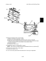
1. Before disassembling or assembling parts of the copier and peripherals,
make sure that the copier power cord is unplugged.
2. The wall outlet should be near the copier and easily accessible.
3. Note that some components of the copier and the paper tray unit are
supplied with electrical voltage even if the main power switch is turned off.
4. If any adjustment or operation check has to be made with exterior covers off
or open while the main switch is turned on, keep hands away from electrified
or mechanically driven components.
5. If the Start key is pressed before the copier completes the warm-up period
(the Start key starts blinking red and green alternatively), keep hands away
from the mechanical and the electrical components as the copier starts
making copies as soon as the warm-up period is completed.
6. The inside and the metal parts of the fusing unit become extremely hot while
the copier is operating. Be careful to avoid touching those components with
your bare hands.
HEALTH SAFETY CONDITIONS
1. Never operate the copier without the ozone filters installed.
2. Always replace the ozone filters with the specified ones at the specified
intervals.
3. Toner and developer are non-toxic, but if you get either of them in your eyes
by accident, it may cause temporary eye discomfort. Try to remove with eye
drops or flush with water as first aid. If unsuccessful, get medical attention.
OBSERVANCE OF ELECTRICAL SAFETY STANDARDS
1. The copier and its peripherals must be installed and maintained by a
customer service representative who has completed the training course on
those models.
2. The NVRAM on the system control board has a lithium battery which can
explode if replaced incorrectly. Replace the NVRAM only with an identical
one. The manufacturer recommends replacing the entire NVRAM. Do not
recharge or burn this battery. Used NVRAM must be handled in accordance
with local regulations.
1. SAFETY AND ECOLOGICAL NOTES FOR DISPOSAL
Do not incinerate toner bottles or used toner. Toner dust may ignite
suddenly when exposed to an open flame.
2. Dispose of used toner, developer, and organic photoconductors in
accordance with local regulations. (These are non-toxic supplies.)
3. Dispose of replaced parts in accordance with local regulations.
4. When keeping used lithium batteries in order to dispose of them later, do not
put more than 100 batteries per sealed box. Storing larger numbers or not
sealing them apart may lead to chemical reactions and heat build-up.
LASER SAFETY
The Center for Devices and Radiological Health (CDRH) prohibits the repair of
laser-based optical units in the field. The optical housing unit can only be repaired
in a factory or at a location with the requisite equipment. The laser subsystem is
replaceable in the field by a qualified Customer Engineer. The laser chassis is not
repairable in the field. Customer engineers are therefore directed to return all
chassis and laser subsystems to the factory or service depot when replacement of
the optical subsystem is required.
IWARNING
Use of controls, or adjustment, or performance of procedures other than
those specified in this manual may result in hazardous radiation exposure.
IWARNING
WARNING: Turn off the main switch before attempting any of the
procedures in the Laser Unit section. Laser beams can seriously damage
your eyes.
CAUTION MARKING:
SPECIFICATIONS
1. OVERALL MACHINE INFORMATION
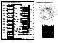
1.1 SPECIFICATIONS
Configuration:
Copy Process:
Original:
Original Size
Copy Paper
Size:
NAD30S / NAD30
NAD40
Desktop
Dry electrostatic transfer system
Sheet/Book
Maximum A3/11" x 17"
Maximum
A3/11" x 17"
Minimum
A5/5.5" x 8.5" lengthwise (Paper tray / Duplex)
A6/5.5" x 8.5" lengthwise (By-pass)
Copy Paper
Weight:
Paper Tray/Duplex:
64 - 105 g/m2, 20 – 28 lb
By-pass
52 - 157 g/m2, 16 – 42 lb
Reproduction
Ratios:
7R5E
Metric version (%):
400, 200, 141, 122,
115, 100, 93, 87, 82,
71, 65, 50, 25
Inch version (%):
400, 200, 155, 129,
121, 100, 93, 85, 78,
73, 65, 50, 25
Both versions:
25% to 400% in 1%
steps
Zoom:
Copying Speed
Resolution:
Gradation:
Warm-up Time:
First Copy Time
(1st Tray):
Copy Number
Input:
7R5E
Metric version (%):
400, 200, 141, 122,
115, 100, 93, 87, 82,
71, 65, 50, 35
Inch version (%):
400, 200, 155, 129,
121, 100, 93, 85, 78,
73, 65, 50, 32
Metric version:
35% to 400% in 1%
steps
Inch version:
32% to 400% in 1%
steps
35 cpm
45 cpm
(A4/11" x 8.5" sideways) (A4/11" x 8.5" sideways)
19 cpm
22 cpm
(A3/11" x 17")
(A3/11" x 17")
Scanning and Printing: 400 dpi
Scanning and Printing: 256 levels
Less than 85 s
Less than 100 s
Less than 3.9 s
Less than 3.2 s
Ten-key pad, 1 to 999
1-1
Note
The duplex
unit and bypass feed
unit are not
standard for
NAD30S.
The duplex
unit and bypass feed
unit are not
standard for
NAD30S.
Full size
Repeat copy
mode
23°C, 73°F
A4/11" x 8.5"
sideways
Count up or
count down
Overall
Information
26 March 1998
SPECIFICATIONS
Manual Image
Density
Selection:
Automatic
Reset:
Auto Shut Off:
Copy Paper
Capacity:
Copy Tray
Capacity:
Toner
Replenishment:
Toner Yield:
Power Source:
Dimensions
(W x D x H)
Weight:
26 March 1998
NAD30S / NAD30
5 steps
NAD40
60 s is the standard setting; it can be changed with a
UP mode.
60 min. is the standard setting; it can be changed
with a UP mode.
Paper Tray: 500 sheets (up to 56 mm, 2.2") x 2
By-pass Feed: 50 sheets (up to 5.5 mm, 0.2")
A4/11" x 8.5": 500 sheets
A3/B4/8.5" x 14"/11" x 17": 250 sheets
Cartridge exchange (700 g/cartridge)
27k copies
(A4 sideways, 6% full black, 1 to 1 copying, ADS
mode)
North America
120V/60Hz, More than 12 A
Europe/Asia
220 – 240V/50, 60Hz, More than 8 A
NAD30S
600 x 640 x 720 mm (23.7" x 25.2" x 28.3")
NAD30/40
670 x 640 x 720 mm (26.4" x 25.2" x 28.3")
NAD30S : 67 kg (147.8 lb),
NAD30/40: 75 kg (166 lb)
1-2
Note
The by-pass
feed unit is
not standard
for NAD30S.
Standard
copy tray
Without
options
SPECIFICATIONS
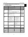
Power Consumption:
Mainframe only
(115 V Machine)
Maximum
Copying
Warm-up
Stand-by
Energy Saver Level 1
Energy Saver Level 2
Auto Shut Off
NAD30S/NAD30
Less than 1.44 kW
Less than 1.15 kW
Less than 1.05 kW
Less than 200 W/h
Ave. 150 W/h
Ave. 130 W/h
Ave. 12 W/h
NAD40
Less than 1.44 kW
Less than 1.3 kW
Less than 1.15 kW
Less than 220 W/h
Ave. 170 W/h
Ave. 150 W/h
Ave. 12 W/h
Note
NAD30S/NAD30
Less than 1.5 kW
Less than 1.10 kW
Less than 1.05 kW
Less than 220 W/h
Ave. 160 W/h
Ave. 154 W/h
Ave. 12 W/h
NAD40
Less than 1.5 kW
Less than 1.2 kW
Less than 1.15 kW
Less than 240 W/h
Ave. 180 W/h
Ave. 168 W/h
Ave. 12 W/h
Note
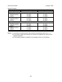
(230 V machine)
Maximum
Copying
Warm-up
Stand-by
Energy Saver Level 1
Energy Saver Level 2
Auto Shut Off
System
(115 V machine)
Maximum
Copying
Warm-up
Stand-by
NAD30S/NAD30
Less than 1.44 kW
Less than 1.2 kW
Less than 1.05 kW
Less than 220 W/h
NAD40
Less than 1.44 kW
Less than 1.35 kW
Less than 1.15 kW
Less than 260 W/h
Note
Without the optional
heaters, fax unit,
and printer
controller.
NAD30S/NAD30
Less than 1.5 kW
Less than 1.15 kW
Less than 1.05 kW
Less than 240 W/h
NAD40
Less than 1.5 kW
Less than 1.25 kW
Less than 1.15 kW
Less than 280 W/h
Note
Without the optional
heaters, fax unit,
and printer
controller.
(230 V machine)
Maximum
Copying
Warm-up
Stand-by
1-3
Overall
Information
26 March 1998
SPECIFICATIONS
26 March 1998
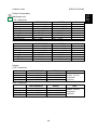
Noise Emission:
Mainframe Only
1. Sound Power Level
Copying
NAD30S/NAD30
69 dB(A)
NAD40
70 dB(A)
Stand-by
NAD30S/NAD30
42 dB(A)
NAD40
42 dB(A)
2. Sound Pressure Level at the Operator’s Position
Copying
NAD30S/NAD30
52 dB(A)
NAD40
56 dB(A)
Stand-by
NAD30S/NAD30
27 dB(A)
NAD40
27 dB(A)
System
73 dB(A)
74 dB(A)
44 dB(A)
44 dB(A)
60 dB(A)
62 dB(A)
28 dB(A)
28 dB(A)
NOTE: 1) The above measurements were made in accordance with ISO 7779.
2) Full system measurements do not include the optional fax unit and the
printer controller.
3) In the above stand-by condition, the polygon motor is not rotating.
1-4
26 March 1998
PAPER EXIT TRAY SELECTION
[C] Longer than
A3, DLT
Overall
Information
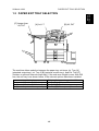
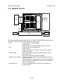
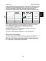
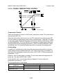
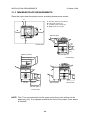
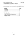
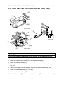
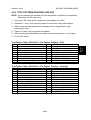
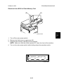
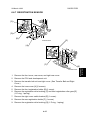
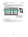
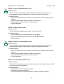
1.2 PAPER EXIT TRAY SELECTION
[B] A3, DLT
[A] A4, LT
A231V508.WMF
The machine allows selection between the paper tray exit trays: Int. Tray [A]
(standard output tray), Int. Tray 2 [B] (optional one-bin tray), and Ext. Tray [C]
(finisher or optional external output tray). If the sub-scan length is more than 330
mm, the exit tray is as shown below, if the relevant options have been installed.
Installed options
Bridge unit & Finisher (1,000-sheet)
Bridge unit & Finisher (3,000-sheet)
Bridge unit & optional ext. output tray
Exit tray for paper longer than 330 mm
Int. Tray [A]
Ext. Tray [C]: The finisher upper tray
Ext. Tray [C]: Ext. output tray
1-5
MACHINE CONFIGURATION
26 March 1998
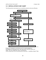
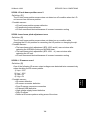
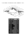
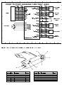
1.3 MACHINE CONFIGURATION
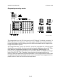
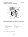
1.3.1 SYSTEM COMPONENTS
12
13
14
2
1
3
4
11
5
6
10
A231V502.WMF
9
1-6
8
7
Version
Copy
Fax
MACHINE CONFIGURATION
Item
Copier (NAD30-S)
Copier (NAD30)
Copier (NAD40)
ARDF (Option)
Platen Cover (Option)
Paper Tray Unit (Option)
LCT (Option)
By-pass Feed Unit (Option – NAD30S only)
Duplex Unit (Option – NAD30S only)
Interchange Unit (Option – NAD30S only)
1-bin Tray (Option)
Bridge Unit (Option)
1000-sheet Finisher (Option)
3000-sheet Finisher (Option – NAD40 only)
Punch Unit (Option for 3000-sheet Finisher)
External Output Tray (Option)
Electrical Sort Kit – 8 MB Memory (Option –
NAD30S only)
Image Enhancement Kit – HDD (Option)
Key Counter Bracket (Option)
Expansion Box (Option)
Fax Unit (Option)
ISDN Unit (Option)
SAF Memory – HDD (Option)
Fax Feature Expander (Option)
400-dpi High Resolution (Option)
Handset (Option – North America only)
Stamp Unit (Option)
1-7
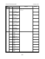
Machine Code
A230
A231
A232
A680
A381
A682
A683
A689
A687
A690
A684
A688
A681
A697
A812-17 (3 holes)
A812-27 (2 holes)
A825
A818
A691
A674
A692
A693
A816
A818-10
A818-11
A818-12
A646
A813
No.
8
8
8
2
1
9
7
5
6
4
3
13
11
10
12
14
Overall
Information
26 March 1998
MACHINE CONFIGURATION
26 March 1998
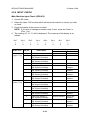
1.3.2 INSTALLABLE OPTION TABLE
Copier options
= Standard, = Available, ∆ = Requires another option, X = Not available
Option
ARDF
Platen Cover
Paper Tray Unit
LCT
By-pass Feed Unit
Duplex Unit
NAD40
∆
∆
3,000-sheet Finisher
X
X
∆
Punch Unit
X
X
∆
External Output Tray
Electrical Sort Kit – 8
MB Memory
Image Enhancement
Kit – HDD
Key Counter Bracket
Expansion Box
Interchange Unit
1-bin Tray
Bridge Unit
1,000-sheet Finisher
NAD30-S
∆
∆
∆
∆
∆
NAD30
∆
∆
∆
∆
∆
Note
Requires the paper tray unit.
Requires the interchange unit
and electrical sort kit.
Requires the interchange unit.
Requires the paper tray unit
and bridge unit.
Requires the paper tray unit
and bridge unit.
Requires the 3000-sheet
finisher.
Requires the bridge unit.
Requires the electrical sort kit
– 8 MB.
It is required only when the
fax option and/or printer
option is installed.
Fax options
All options for the fax unit are available when the fax unit has been installed.
1-8
26 March 1998
MECHANICAL COMPONENT LAYOUT
1
2
3
4
5
6
7
8
Overall
Information
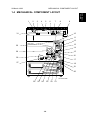
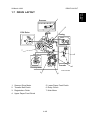
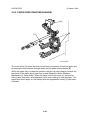
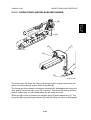
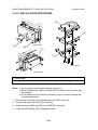
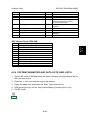
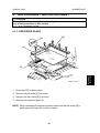
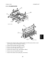
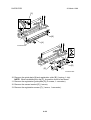
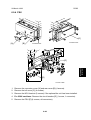
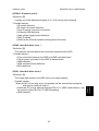
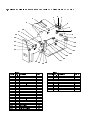
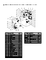
1.4 MECHANICAL COMPONENT LAYOUT
9
10
31
11
12
13
30
14
29
15
16
28
17
27
18
19
20
A231V503.WMF
26
25
24
23
1-9
22
21
MECHANICAL COMPONENT LAYOUT
26 March 1998
1. Exposure Glass
17. Registration Roller
2. 2nd Mirror
18. Upper Relay Rollers
3. Original Width Sensors
19. Feed Roller
4. 1st Mirror
20. Separation Roller
5. Exposure Lamp
21. Pick-up Roller
6. Original Length Sensors
22. Bottom Plate
7. Lens
23. Development Unit
8. SBU
24. Charge Roller
9. Scanner Motor
25. Fθ Mirror
10. Paper Exit Sensor
26. Barrel Toroidal Lens (BTL)
11. Exit Junction Gate
27. Polygonal Mirror Motor
12. Hot Roller
28. Laser Unit
13. Pressure Roller
29. Toner Supply Bottle Holder
14. Transfer Belt Cleaning Blade
30. Exit Roller
15. OPC Drum
31. 3rd Mirror
16. Transfer Belt
1-10
26 March 1998
PAPER PATH
Overall
Information
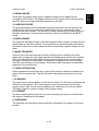
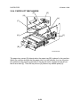
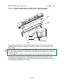
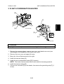
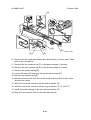
1.5 PAPER PATH
Optional 1-bin Tray
Optional ARDF
Optional Bridge Unit
Optional
Interchange Unit
Optional Duplex
Unit
Optional By-pass
Feed Unit
1000-sheet Finisher
A230v102.wmf
Optional Paper Tray
Unit
Optional LCT
1-11
ELECTRICAL COMPONENT DESCRIPTIONS
26 March 1998
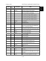
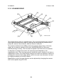
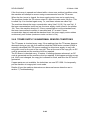
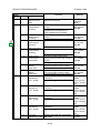
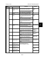
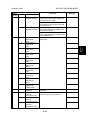
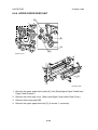
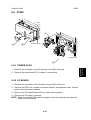
1.6 ELECTRICAL COMPONENT DESCRIPTIONS
Refer to the electrical component layout and the point-to-point diagram on the
waterproof paper in the pocket for the locations of these components.
Index
Description
No.
Printed Circuit Boards
PCB1
58
BICU (Base
Engine & Image
Control Unit)
PCB2
55
PSU (Power
Supply Unit)
Symbol
PCB3
61
IOB (Input/Output
Board)
PCB4
62
PCB5
63
PCB6
9
PCB7
7
Paper Feed
Control (PFB)
High Voltage
Supply
SBU (Sensor
Board Unit)
SIB (Scanner
Interface Board)
PCB8
11
Operation Panel
PCB9
PCB10
4
19
PCB11
54
Lamp Stabilizer
LDDR (Laser
Diode Driver)
SIFB (Scanner
Interface Board)
Motors
M1
M2
M3
M4
M5
35
8
45
22
20
Main
Scanner Drive
Tray Lift
Polygonal Mirror
LD Positioning
M6
M7
M8
36
37
34
Cooling Fan
Exhaust Fan
Toner Supply
M9
56
PSU Cooling Fan
Note
Controls all copier functions both directly and
through other control boards.
Provides dc power to the system and ac
power to the fusing lamp and optional
heaters.
Controls the mechanical parts of the printer
(excluding the paper feed section), and the
fusing lamp power.
Controls the mechanical parts of all paper
feed sections.
Supplies high voltage to the drum charge
roller, development roller, and transfer belt.
Contains the CCD, and outputs a video signal
to the BICU board.
Controls the scanner carriages and passes
signals from the scanner unit to the BICU
board.
Controls the LCD and LED matrix and
monitors the key matrix.
Provides dc power to the exposure lamp.
Controls the laser diode.
Passes signals between the SIFB and BICU
boards.
Drives the main body components.
Drives the 1st and 2nd scanners.
Raises the bottom plate in the paper tray.
Turns the polygonal mirror.
Rotates the LD unit to adjust the LD beam
pitch when a different resolution is selected.
Removes heat from the main PCBs.
Removes heat from around the fusing unit.
Rotates the toner bottle to supply toner to the
development unit.
Removes heat from the PSU.
1-12
Symbol
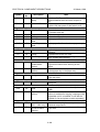
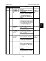
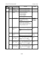
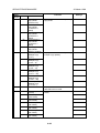
ELECTRICAL COMPONENT DESCRIPTIONS
Index
No.
Description
Sensors
S1
2
S2
3
Scanner Home
Position
Platen Cover
S3
12
Original Width
S4
5
Original Length-1
S5
6
Original Length-2
S6
21
S7
17
S8
S9
24
27
LD Unit Home
Position
Toner Density
(TD)
Paper Exit
Registration
S10
26
S11
28
S12
30
S13
29
Image Density
(ID)
Upper Paper
Height
Lower Paper
Height
Upper Paper End
S14
31
Lower Paper End
S15
S16
S17
33
32
48
Upper Relay
Lower Relay
Upper Tray
S18
46
Lower Tray
S19
38
S20
18
Transfer Belt
Position
Toner Overflow
Switches
SW1
43
SW2
49
SW3
51
Right Lower
Cover
Right Upper
Cover
Main Power
Switch
Note
Informs the CPU when the 1st and 2nd
scanners are at the home position.
Informs the CPU whether the platen cover is
up or down (related to APS/ARE functions).
ARE: Auto Reduce and Enlarge
Detects the width of the original. This is one
of the APS (Auto Paper Select) sensors.
Detects the length of the original. This is one
of the APS (Auto Paper Select) sensors.
Detects the length of the original. This is one
of the APS (Auto Paper Select) sensors.
Informs the CPU when the LD unit is at the
home positon.
Detects the amount of toner inside the
development unit.
Detects misfeeds.
Detects the leading edge of the copy paper to
determine the stop timing of the paper feed
clutch, and detects misfeeds.
Detects the density of various patterns and
the reflectivity of the drum for process control.
Detects when the paper in the upper paper
tray is at the feed height.
Detects when the paper in the lower paper
tray is at the feed height.
Informs the CPU when the upper paper tray
runs out of paper.
Informs the CPU when the lower paper tray
runs out of paper.
Detects misfeeds.
Detects misfeeds.
Informs the CPU whether the upper paper
tray is set into the machine or not.
Informs the CPU whether the lower paper
tray is set into the machine or not.
Informs the CPU of the current position of the
transfer belt unit.
Detects toner overflow in the toner collection
tank.
Detects whether the right lower cover is open
or closed.
Cut the +5VLD and +24V dc power line and
detects whether the right upper cover is open
or closed.
Supplies power to the copier. If this is off,
there is no power supplied to the copier.
1-13
Overall
Information
26 March 1998
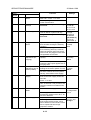
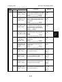
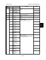
ELECTRICAL COMPONENT DESCRIPTIONS
SW4
Index
No.
52
SW5
10
Symbol
Description
Front Cover
Safety
Operation Switch
Magnetic Clutches
CL1
39
Transfer Belt
Note
Cuts the +5VLD and +24V dc power line and
detects whether the front cover is open or
not.
Provides power for machine operation. The
machine still has power if this switch is off.
Controls the touch and release movement of
the transfer belt unit.
Drives the registration rollers.
Drives the relay rollers.
Starts paper feed from the upper paper tray.
CL2
CL3
CL4
40
44
41
CL5
42
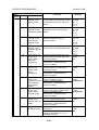
Lamps
L1
13
Exposure
16
25
Fusing
Quenching
1
Optics Anticondensation
(option)
Tray
(option)
Turns on when the main power switch is off
to prevent moisture from forming on the
optics.
Turns on when the main power switch is off
to keep paper dry in the paper tray.
Thermistors
TH1
14
Fusing
Monitors the temperature at the central area
of the hot roller.
Thermofuses
TF1
15
Fusing
Provides back up overheat protection in the
fusing unit.
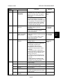
Counters
CO1
50
Total
CO2
N/A
Key
(option)
Keeps track of the total number of prints
made.
Used for control of authorized use. If this
feature is enabled for copying, copying will be
impossible until it is installed. It can also be
enabled for fax and printer modes separately.
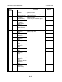
Others
CB1
57
LSD
23
Circuit Breaker
(220 ~ 240V only)
Laser
Synchronization
Detector
L2
L3
Heaters
H1
H2
47
Registration
Relay
Upper Paper
Feed
Lower Paper
Feed
26 March 1998
Starts paper feed from the lower paper tray.
Applies high intensity light to the original for
exposure.
Provides heat to the hot roller.
Neutralizes any charge remaining on the
drum surface after cleaning.
Provides back-up high current protection for
electrical components.
Detects the laser beam at the start of the
main scan.
1-14
26 March 1998
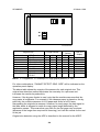
DRIVE LAYOUT
Scanner
Overall
Information
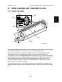
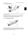
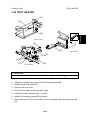
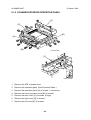
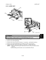
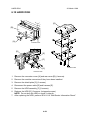
1.7 DRIVE LAYOUT
1
2
PCU Drive
Fusing
7
3
Transfer
Development
A230V108.WMF
6
5
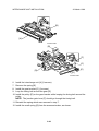
1. Scanner Drive Motor
5. Lower Paper Feed Clutch
2. Transfer Belt Clutch
6. Relay Clutch
3. Registration Clutch
7. Main Motor
4. Upper Paper Feed Clutch
1-15
4
COPY PROCESS
26 March 1998
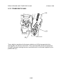
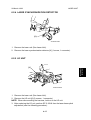
1.8 COPY PROCESS
1.8.1 OVERVIEW
A231v500.WMF
1
8
7
9
6
2
5
3
4
A230V101.WMF
1. EXPOSURE
A xenon lamp exposes the original. Light reflected from the original passes to the
CCD, where it is converted into an analog data signal. This data is converted to a
digital signal, processed, and stored in the memory. At the time of printing, the data
is retrieved and sent to the laser diode. For multi-copy runs, the original is scanned
once only and stored to the memory.
1-16
COPY PROCESS
2. DRUM CHARGE
In the dark, the charge roller gives a negative charge to the organic photoconductive (OPC) drum. The charge remains on the surface of the drum because
the OPC layer has a high electrical resistance in the dark.
3. LASER EXPOSURE
The processed data from the scanned original is retrieved from the memory and
transferred to the drum by two laser beams, which form an electrostatic latent
image on the drum surface. The amount of charge remaining as a latent image on
the drum depends on the laser beam intensity, which is controlled by the BICU
board.
4. DEVELOPMENT
The magnetic developer brush on the development roller comes in contact with the
latent image on the drum surface. Toner particles are electrostatically attracted to
the areas of the drum surface where the laser reduced the negative charge on the
drum.
5. IMAGE TRANSFER
Paper is fed to the area between the drum surface and the transfer belt at the
proper time to align the copy paper and the developed image on the drum surface.
Then, the transfer bias roller applies a high positive charge to the reverse side of
the paper through the transfer belt. This positive charge pulls the toner particles
from the drum surface on to the paper. At the same time, the paper is electrically
attracted to the transfer belt.
6. PAPER SEPARATION
Paper separates from the drum as a result of the electrical attraction between the
paper and the transfer belt. The pick-off pawls help separate the paper from the
drum.
7. ID SENSOR
The laser forms a sensor pattern on the drum surface. The ID sensor measures the
reflectivity of the pattern. The output signal is one of the factors used for toner
supply control. Also, the ID sensor measures the reflectivity of the drum surface.
The output signal is used for charge roller voltage control.
8. CLEANING
The drum cleaning blade removes any toner remaining on the drum surface after
the image is transferred to the paper.
9. QUENCHING
The light from the quenching lamp electrically neutralizes the charge on the drum
surface.
1-17
Overall
Information
26 March 1998
BOARD STRUCTURE
26 March 1998
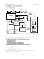
1.9 BOARD STRUCTURE
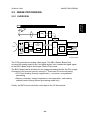
1.9.1 BLOCK DIAGRAM
Scanner
Motor
APS
Sensors
MSU
Lamp
Stabilizer
Exposure
Lamp
HDD
LDDR
LSD
SBU
Polygon
Motor
SIFB
SIB
Op.
Panel
BICU
Mother
Board
ARDF
1-bin Tray
Fax Controller
Printer Controller
PSU
Main
Motor
Bridge Unit
High
Voltage
Supply
LD Positioning
Motor
LD H.P
Sensor
IOB
Duplex
Finisher
Counter
Fans
Sensors
Clutches
Paper
Feed
Controller
(PFB)
Paper
Tray Unit
Sensors
Clutches
LCT
: Standard
: Option
A231V501.WMF
1-18
BOARD STRUCTURE
1.9.2 DESCRIPTIONS
1. BICU (Base Engine and Image Control Unit)
This is the main board. It controls the following functions.
• Engine sequence
• Timing control for peripherals
• Image processing, video control
• Operation control
• Application boards (fax, printer, hard disk)
2. IOB (Input/Output Board)
The IOB handles the following functions.
• Drive control for the sensors, motors, and solenoids of the printer
• PWM control for high voltage supply board
• Serial interface with peripherals
• Fusing control
3. SBU (Sensor Board Unit)
The SBU receives the analog signals from the CCD and converts them into digital
signals.
4. SIB (Scanner Interface Board)
This board controls the scanner motor and passes signals between the BICU board
and the component parts of the scanner unit. Also, it transmits the video signals
from the SBU to the BICU board.
5. SIFB (Scanner Interface Board)
This board passes signals between the SIB and BICU.
6. Mother Board (Option)
This board interfaces the BICU with the fax controller and/or the printer controller.
The mother board is part of the expansion box option.
1-19
Overall
Information
26 March 1998
26 March 1998
SCANNING
2. DETAILED SECTION DESCRIPTIONS
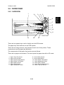
2.1 SCANNING
[E]
[G]
[C]
[A]
[F]
[D]
[B]
A230D101.WMF
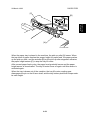
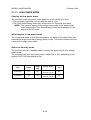
The original is illuminated by the exposure lamp (a xenon lamp in this model) [A].
The image is reflected onto a CCD (charge coupled device) [B] via the 1st, 2nd,
and 3rd mirrors, and through the lens [C].
The 1st scanner [D] consists of the exposure lamp, a reflector [E], and the 1st
mirror [F].
The exposure lamp is energized by a dc supply to avoid uneven light intensity
while the 1st scanner moves in the sub scan direction (down the page). The entire
exposure lamp surface is frosted to ensure even exposure in the main scan
direction (across the page).
The light reflected by the reflector is of almost equal intensity in all directions, to
reduce shadows on pasted originals.
An optics anti-condensation heater [G] is available as an option. It can be installed
on the left side of the scanner. It turns on whenever the power cord is plugged in.
2-1
Detailed
Descriptions
2.1.1 OVERVIEW
SCANNING
26 March 1998
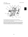
2.1.2 SCANNER DRIVE
[G]
[B]
[A]
[E]
[D]
[C]
[G]
[E]
[F]
A230D102.WMF
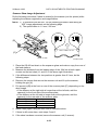
The scanner drive motor is a stepper motor. The 1st and 2nd scanners [A, B] are
driven by the scanner drive motor [C] through the timing belt [D], scanner drive
pulley [E], scanner drive shaft [F], and two scanner wires [G].
The scanner interface board (SIB) controls the scanner drive motor. In full size
mode, the 1st scanner speed is 180 mm/s (NAD30S/NAD30) or 230 mm/s
(NAD40) during scanning. The 2nd scanner speed is half that of the 1st scanner.
In reduction or enlargement mode, the scanning speed depends on the
magnification ratio. The returning speed is always the same, whether in full size or
magnification mode. The image length change in the sub scan direction is done by
changing the scanner drive motor speed, and in the main scan direction it is done
by image processing on the BICU board.
Magnification in the sub-scan direction can be adjusted by changing the scanner
drive motor speed using SP4-008.
2-2
26 March 1998
SCANNING
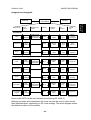
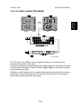
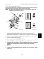
2.1.3 ORIGINAL SIZE DETECTION IN PLATEN MODE
[A]
[B]
A230D103.WMF
In the optics cavity for original size detection, there are five reflective sensors. The
original width sensors [A] detect the original width, and the original length sensors
[B] detect the original length. These are the APS (Auto Paper Select) sensors.
Each APS sensor is a reflective photosensor.
While the power is on, these sensors are active and the original size data is always
sent to the CPU. However, the CPU checks the data only when the platen cover
sensor [C] is activated. This is when the platen reaches about 15 cm above the
exposure glass, for example while it is being closed. The main CPU can recognize
the original size from the on/off signals from the APS sensors.
If the copy is made with the platen fully open, the main CPU decides the original
size from the sensor outputs when the Start key is pressed.
2-3
Detailed
Descriptions
[C]
SCANNING
26 March 1998
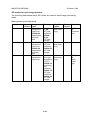
L1
L2
L3
W1
W2
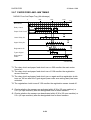
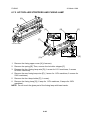
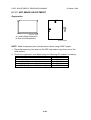
A231D500.WMF
Original Size
A4/A3 version
A3
B4
F4
A4-L
B5-L
A4-S
B5-S
A5-L, A5-S
LT/DLT version
11”x17”
10”x14”
8.5”x14” (8”x13”)
8.5”x11”
11”x8.5”
5.5”x8.5”,
8.5”x5.5”
Length Sensor
L3
O
O
O
X
X
X
X
X
L2
O
O
O
O
X
X
X
X
L1
O
O
O
O
O
X
X
X
Width
Sensor
W2
W1
O
O
X
O
X
X
X
X
X
X
O
O
X
O
X
X
SP4-301
display
00011111
00011101
00011100
00001100
00000100
00000011
00000001
00000000
NOTE: -L: Lengthwise, -S: Sideways, O: High (paper present) X: Low
For other combinations, "CANNOT DETECT ORIG. SIZE" will be indicated on the
operation panel display.
The above table shows the outputs of the sensors for each original size. This
original size detection method eliminates the necessity for a pre-scan and
increases the machine's productivity.
However, if the by-pass feeder is used, note that the machine assumes that the
copy paper is lengthwise. For example, if A4 sideways paper is placed on the bypass tray, the machine assumes it is A3 paper and scans a full A3 area,
disregarding the original size sensors. However, for each page, the data signal to
the laser diode is stopped to match the copy paper length detected by the
registration sensor. This means that copy time for the first page may be slower
(because of the longer time required for scanning), but it will be normal for the rest
of the job.
Original size detection using the ADF is described in the manual for the ARDF.
2-4
26 March 1998
IMAGE PROCESSING
2.2 IMAGE PROCESSING
CCD
Detailed
Descriptions
2.2.1 OVERVIEW
SBU
SIB
SIFB
LD
Driver
Drum
LD
Driver
Fax Controller
LD
Controller
(GAVD)
IPU
FCI
LDDR
Memory
Control
IC
BICU
MSU
HDD
Printer
Controller
A231D531.WMF
The CCD generates an analog video signal. The SBU (Sensor Board Unit)
converts the analog signal to an 8-bit digital signal, then it sends the digital signal
to the BICU (Base-engine and Image Control Unit) board.
The BICU board can be divided into two image processing blocks; the IPU (Image
Processing Unit) and the memory control IC. These two ICs do the following:
• IPU: Auto shading, filtering, magnification, γ correction, and gradation
processing
• Memory controller: Image compression, decompression, and memory
address control (binary picture processing mode only)
Finally, the BICU board sends the video data to the LD drive board.
2-5
IMAGE PROCESSING
26 March 1998
2.2.2 SBU
E
Analog
Processing IC
SIB
CCD
SBU
O
A/D
SIFB
NAD30S and NAD30
BICU
IPU
8 bit data
GA
CCD
Analog
Processing IC1
SIB
SBU
O
A/D 1
Analog
Processing IC2
A/D 2
BICU
8 bit data
IPU
GA
E
SIFB
NAD40
8 bit data
A231D532.WMF
The CCD converts the light reflected from the original into an analog signal. The
CCD line has 5,000 pixels and the resolution is 400 dpi (15.7 lines/mm).
The CCD has two output lines, for odd and even pixels, to the analog processing
IC. For NAD30S and NAD30, there is one analog processing IC. For NAD40, there
are two analog processing ICs; one handles odd pixels and the other handles even
pixels. The analog processing IC performs the following operations on the signals
from the CCD:
1. Z/C (Zero Clamp):
Adjusts the black level reference for even pixels to match the odd pixels.
2. Signal Composition: (NAD30S and NAD30 only)
Analog signals for odd and even pixels from the CCD are merged by a switching
device.
3. Signal Amplification
The analog signal is amplified by operational amplifiers in the AGC circuit. The
maximum gains of the operational amplifiers are controlled by the CPU on the
BICU board.
After the above processing, the analog signals are converted to 8-bit signals by the
A/D converter. This gives a value for each pixel on a scale of 256 grades. Then,
this data goes to the BICU board thorough the SIB and SIFB boards. (NAD30S and
NAD30 each send one 8-bit signal, and NAD40 sends two 8-bit signals to the BICU
board).
2-6
26 March 1998
IMAGE PROCESSING
2.2.3 AUTO IMAGE DENSITY (ADS)
15mm
75mm
Sub scan direction
A231D530.WMf
This mode prevents the background of an original from appearing on copies.
The copier scans the auto image density detection area [A]. This corresponds to a
narrow strip at one end of the main scan line, as shown in the diagram. As the
scanner scans down the page, the IPU on the BICU detects the peak white level
for each scan line, within this narrow strip only. From this peak white level, the IPU
determines the reference value for A/D conversion for the scan line. Then, the IPU
sends the reference value to the A/D controller on the SBU.
When an original with a gray background is scanned, the density of the gray area
is the peak white level density. Therefore, the original background will not appear
on copies. Because peak level data is taken for each scan line, ADS corrects for
any changes in background density down the page.
As with previous digital copiers, the user can select manual image density when
selecting auto image density mode and the machine will use both settings when
processing the original.
2-7
Detailed
Descriptions
[A]
0.5mm
IMAGE PROCESSING
26 March 1998
2.2.4 IPU (IMAGE PROCESSING UNIT)
Overview
SIB
Fax Controller
SIFB
IPU
MB
SBU
Printer Controller
LDDR
FCI
LD1
LD2
MSU
BICU
DRAM
GA 2
HDD
GA 1
GAVD
SIMM
A231D520.WMF
The image data from the SBU goes to the IPU (Image Processing Unit) IC on the
BICU board, which carries out the following processes on the image data:
1. Auto shading
2. Filtering (MTF and smoothing)
3. Magnification
4. γ correction
5. Grayscale processing
6. Binary picture processing
7. Error diffusion
8. Dithering
9. Video path control
10. Test pattern generation
The image data then goes to either the LDDR or the memory control IC (GA 1)
depending on the selected copy modes.
2-8
26 March 1998
IMAGE PROCESSING
Image processing path
Image
Processing
Copy Mode
Input
correct.
Background
erase
Filtering
Printing
Magnification
ID
control
Gradation
Binary Picture
Processing
MTF
Magnification
γ Correction
Binary
Picture
Processing
Auto
Shading
MTF
Magnification
γ Correction
Error
diffusion
Auto
Shading
Smoothing
Magnification
γ Correction
8x8
Dithering
MTF
Magnification
γ Correction
Grayscale
Letter
Auto
Shading
Letter/Photo
Photo
Background/
Independent
Dot Erase
Grayscale Processing
Background/
Independent
Dot Erase
Letter
Auto
Shading
Letter/Photo
Auto
Shading
MTF
Magnification
γ Correction
Error
diffusion
Photo
Auto
Shading
Smoothing
Magnification
γ Correction
6x6
Dithering
Generation
Auto
Shading
MTF
Magnification
γ Correction
Grayscale/
Line width
correction
Low Density
Original
Auto
Shading
MTF
Magnification
γ Correction
Grayscale
Background/
Independent
Dot Erase
A231D533.WMF
Photo mode: MTF can be used instead of smoothing (SP 4-904-3).
Background erase and independent dot erase can also be used in other modes
than indicated above, depending on SP mode settings. The above diagram shows
the default condition of the machine.
2-9
Detailed
Descriptions
Scanning
IMAGE PROCESSING
26 March 1998
SP modes for each image process
The following table shows which SP modes are used for each image processing
mode.
Binary picture processing mode
Input
correct
---
Background
erase
SP4903-34
Background
erase level
SP4903-29
Independent
dot erase
level
Letter/Photo
---
Photo
---
SP4903-35
Background
erase level
SP4903-30
Independent
dot erase
level
SP4903-36
Background
erase level
Copy mode
Letter
Filtering
SP490341~44
MTF filter
coefficient
SP490350~53
MTF filter
strength
SP4903-47
MTF filter
coefficient
SP4903-55
MTF filter
strength
SP4904-3
Filter type
(smoothing
or MTF)
SP4903-16
Smoothing
filter
coefficient
SP4903-15
MTF filter
coefficient
SP4903-24
MTF filter
strength
2-10
Magnification
SP2909-1
Main scan
mag.
ID
control
---
SP2909-1
Main scan
mag.
---
SP2909-1
Main scan
mag.
---
Gradation
SP490412
Threshold
level
---
SP490418
Dither
matrix
type
26 March 1998
IMAGE PROCESSING
Grayscale processing
Input
correct
Background
erase
SP4903-34
Background
erase level
SP4903-28
Independent
dot erase
level
Letter/
Photo
SP4903-35
Background
erase level
SP4903-30
Independent
dot erase
level
Photo
SP4903-36
Background
erase level
Copied
Original
SP4903-37
Background
erase level
SP4903-32
Independent
dot erase
level
Low
Density
Original
SP4903-31
Independent
dot erase
level
Filtering
SP490311~14
MTF filter
coefficient
SP490320~23
MTF filter
strength
SP4903-17
MTF filter
coefficient
SP4903-25
MTF filter
strength
Magnification
SP2909-1
Main scan
mag.
SP2909-1
Main scan
mag.
SP4904-3
Filter type
(smoothing
or MTF)
SP4903-16
Smoothing
filter
coefficient
SP4903-15
MTF filter
coefficient
SP4903-24
MTF filter
strength
SP4903-19
MTF filter
coefficient
SP4903-27
MTF filter
strength
SP2909-1
Main scan
mag.
SP4903-18
MTF filter
coefficient
SP4903-26
MTF filter
strength
SP2909-1
Main scan
mag.
2-11
SP2909-1
Main scan
mag.
ID
cont.
Gradation
SP4903-38
Error
diffusion
on/off
SP4907
Text/photo
auto
separation
SP4904-7
Gradation
type in text
areas
SP4904-8
Gradation
type in
photo areas
SP4904-2
Dither
matrix type
SP4904-6
Line width
correction
type
SP4903-38
Error
diffusion
on/off
SP4903-38
Error
diffusion
on/off
Detailed
Descriptions
Copy
mode
Letter
IMAGE PROCESSING
26 March 1998
Auto shading
Auto shading does two things.
• Zeroes the black level for each scan line of data
• Corrects for variations in white level across the main scan.
Background erase
Output
255
Input
0
20
255
A231D527.WMF
By default, this process is used only in letter mode and copied original mode.
However, it can be enabled for other modes by SP mode.
Usually, dirty background is erased using the Auto Image Density (ADS) function.
However, sometimes, dirty background areas will still appear. These can be erased
by this function.
If any low image density data which is lower than a threshold level remains after
auto shading, this data will be changed to “0” = white.
The threshold level can be changed with SP4-903-34 ~ 37. For example, for letter
mode, use SP 4-903-34.
2-12
26 March 1998
IMAGE PROCESSING
Independent dot erase
Detailed
Descriptions
Original image
A1
A2
A6
A8
A5
0
A7
0
A10 A11 A12
0
A3
C
A9
A4
0
30
7
0
90
0
0
0
0
0
Image data
3 x 5 area
A231D528.WMF
By default, this process is used only in letter mode and copied original mode.
However, it can be enabled for other modes by SP mode. It erases independent
black dots appearing in the copy or reduces their image density.
The software compares each pixel (C in the diagram above left) with the pixels
around the edges of the surrounding 3 x 5 area. If the sum of the pixels at the
edges is smaller than the threshold value stored in SP4-903-28 ~ 32 (e.g., for letter
mode with binary picture processing, it is SP 4-903-29), the object pixel is changed
to 0 (white) or reduced in density to an average of the pixels around the edge,
depending on the SP mode setting. Each SP mode has 16 levels as follows.
A= The sum of the pixels at the edges
SP mode
value
0
1
2
3
4
5
6
7
Function
Disabled
If A < 16, the pixel is deleted
If A < 32, the pixel is deleted
If A < 48, the pixel is deleted
If A < 64, the pixel is deleted
If A < 80, the pixel is deleted
If A < 96, the pixel is deleted
If A < 128, the pixel is deleted
SP mode
value
8
9
10
11
12
13
14
15
Function
Disabled
If A < 16, density is reduced
If A < 32, density is reduced
If A < 48, density is reduced
If A < 64, density is reduced
If A < 80, density is reduced
If A < 96, density is reduced
If A < 128, density is reduced
Pixel density reduction works as follows. For the example in the above drawing, ,
when the SP mode value is “11”, the sum of the pixels around the edge is less than
48, the object pixel value is reduced from “90” to “3” as shown below.
A: (0 + 0 + 30 + 7 + 0 + 0 + 0 + 0 + 0 + 0 + 0 + 0) / 12 = 3
2-13
IMAGE PROCESSING
26 March 1998
Filtering, main scan magnification/reduction
Overview
After auto shading, the image data is processed by both filtering and main scan
magnification. However, to reduce the occurrence of moire in the image, the
processing order depends on the reproduction ratio, as follows.
1. 64% reduction or less
Main Scan Reduction → Filtering
2. 65% reduction or higher
Filtering → Main Scan Magnification
Filtering
There are two software filters for enhancing the desired image qualities of the
selected original mode: the MTF filter and the smoothing filter.
The MTF filter emphasizes sharpness and is used in text and text/photo modes.
The smoothing filter is used in photo mode.
The relationships between the coefficient of the filter and the filter strengths are as
follows. The filter strengths and the coefficient for each mode can be adjusted with
SP4-903.
MTF Filter Coefficient (SP4-903-11~15, 17~19, 41~47)
(Weak) 11 → 8 → 2 → 1 → 9 → 0 → 5 → 4 → 10 → 7 → 3 → 6 (Strong)
MTF Filter Strength (SP4-903-20~27, 50~53, 55)
(Weak) x0.25 → x0.5 → x1 → x2 → x4 (Strong)
Smoothing Filter Coefficient (SP4-903-16)
(Weak) 7 → 6 → 0 → 5 → 2 → 1 → 3 → 4 (Strong)
A stronger MTF filter leads to sharper lines. A stronger smoothing filter leads to a
greater degree of smoothing.
Refer to the tables in ‘SP Modes for Each Image Process’ for more information.
Main scan magnification/reduction
Reduction and enlargement in the sub scan direction are done by changing the
scanner speed. However, reduction and enlargement in the main scan direction
are handled by the IPU chip.
To reduce or enlarge an image, imaginary points are calculated that would
correspond to a physical enlargement or reduction of the image. The image density
is then calculated for each of the imaginary points based on the image data of the
nearest four true points. The calculated image data then becomes the new
(reduced or enlarged) image data.
2-14
26 March 1998
IMAGE PROCESSING
Gamma (γγ) corrEctionr
Scanner gamma correction corrects the data output to the IPU to account for the
characteristics of the scanner (e.g., CCD response, scanner optics).
Printer gamma correction corrects the data output from the IPU to the laser diode
to account for the characteristics of the printer (e.g., the characteristics of the drum,
laser diode, and lenses).
The data for the scanner and printer gamma correction are fixed and stored in the
memory. There are no SP adjustments in this machine.
Gradation processing
These are four types of gradation processing:
1. Grayscale processing: This has 256 output levels for each pixel. When the
optional image enhancement kit (HDD) is installed, the binary picture
processing mode cannot be selected.
2. Binary picture processing: This has only two output levels (black and white).,
and is used only in memory copying (only without HDD) and fax transmission.
3. Error diffusion: In text/photo mode, this is used with either grayscale processing
or binary processing.
4. Dithering: In photo mode, this is used with either grayscale processing or binary
processing
These four processes are used as follows.
1. Grayscale processing mode
Text mode
Grayscale processing
Text/photo mode:
Error diffusion (256 levels)
Photo mode:
Dithering (256 levels)
Copied original mode:
Grayscale processing + line width correction
Low density original mode Grayscale processing
2. Binary picture processing mode
Text mode:
Binary picture processing
Text/photo mode:
Error diffusion (2 levels)
Photo mode:
Dithering (2 levels)
The above information is expressed as a diagram in the Image Processing Path
section.
2-15
Detailed
Descriptions
Gamma correction ensures accurate generation of the various shades in the gray
scale from black to white, accounting for the characteristics of the scanner and
printer.
IMAGE PROCESSING
26 March 1998
Grayscale processing
As stated on the previous page, this process generates up to 256 image density
levels for each pixel. To realize this, this machine uses a form of pulse width
modulation. In this machine, pulse width modulation consists of the following
processes:
• Laser diode pulse positioning
• Laser diode power/pulse width modulation
Laser diode power and pulse width modulation is done by the laser diode drive
board (LDDR). Briefly, the width of the laser pulse for a pixel depends on the output
level (from 0 to 255) required for the pixel.
This machine can also change the laser pulse position (at the left side of the pixel,
at the center, or at the right side) automatically, depending on the location of the
image pixel so that the edges of characters and lines become clearer. There is no
SP mode adjustment for this, unlike in some earlier models.
Binary picture processing
Each video signal level is converted from 8-bit to 1-bit (black and white image data)
in accordance with a threshold value.
The threshold value can be adjusted with SP 4-904-12.
Error diffusion
This is used only in text/photo mode.
The error diffusion process reduces the difference in contrast between light and
dark areas of a halftone image. Each pixel is corrected using the difference
between it and the surrounding pixels. The corrected pixels are then compared with
an error diffusion matrix. Separate error diffusion matrixes are used for copy mode
and fax mode.
1. Grayscale processing mode
The output image signal level has 9 levels (from white to black). There is only
one matrix available.
2. Binary picture processing mode
The output image signal level has just 2 levels (white and black).
2-16
26 March 1998
IMAGE PROCESSING
Dithering
This is only used in photo mode.
1. Grayscale processing mode
The matrix type can be selected with SP4-904-2.
2. Binary picture processing
The matrix type can be selected with SP4-904-18.
Line width correction
This function is effective only in copied original mode.
Usually, lines will bulge in the main scan direction as a result of the
negative/positive development system that is used in this model. So, pixels on
edges between black and white areas are compared with adjacent pixels, and if the
pixel is on a line, the line thickness will be reduced.
The line width correction is done in the IPU chip.
The line width correction type can be selected with SP4-904-6.
2-17
Detailed
Descriptions
Each pixel is compared with a pixel in a dither matrix. Several matrixes are
available, to increase or decrease the detail on the copy.
IMAGE PROCESSING
26 March 1998
2.2.5 MEMORY BLOCK
FIFO
MSU
IPU
HDD
CPU BUS
GA 2
DRAM
GA 1
SIMM
A231D519.WMF
The memory block consists of the GA1 IC, GA2 IC, DRAM, SIMM, and the hard
disk drive. The functions of each device are as follows.
GA 1:
GA 2:
DRAM (4 MB):
SIMM memory (8 MB):
Hard Disk Drive:
Compressing the 1-bit image data
Image rotation
Image transfer to the DRAM, SIMM memory and GA 2
Compressing the 8-bit image data
Image rotation
Image data transfer to the HDD, FIFO memory, and GA1
Controls the HDD
Stores compressed data in grayscale and binary picture
processing mode.
Page memory (2 MB), working area (2 MB)
Stores compressed data with grayscale and binary picture
processing mode.
In binary picture processing mode, all the memory capacity is
used for storing the image data. At this time, the DRAM is
used for a working area.
Stores compressed data in grayscale mode and stores
archive file data.
2-18
26 March 1998
IMAGE PROCESSING
Copy Mode
One-to-one
Multiple copy of
single page original
Multiple copy of
multi-page original
Duplex Copy
Sort
Image Rotation
Gradation
Processing
Binary/Grayscale
Binary/Grayscale
Binary/Grayscale
Binary/Grayscale
Binary/Grayscale
Binary/Grayscale
DRAM
(4 MB)
DRAM + SIMM
(4 + 8 MB)
O/O
O/O
DRAM + SIMM
+ HDD
(12MB+1.6 GB)
X/O
O/O
O/O
X/O
O/X
O/O
X/O
X/X
X/X
O/X
O/X
O/X
O/O
X/O
X/O
X/O
Key:
O / O: Possible in both binary and grayscale mode if this equipment is installed
O / X: Possible only in binary mode if this equipment is installed
X / O: Possible only in grayscale mode if this equipment is installed
X / X: Not possible in either mode
Example: Multiple copy of multi-page original is impossible with greyscale
processing if only the DRAM is installed
Note that the SIMM is standard equipment for the NAD30 and NAD40.
Binary picture processing mode
The data which was treated with binary picture processing goes to the GA1 IC. The
data is first compressed and the compressed data is stored in the DRAM and
SIMM memory. When printing, the data from the DRAM and SIMM memory goes
back to the GA1 IC, where the data is decompressed and image editing is done
(e.g., image rotation, repeat image, combine image).
2-19
Detailed
Descriptions
Image compression is done for both gradation modes (grayscale and binary picture
processing) and the compressed data is stored. However, there are limitations in
copy mode, depending on the memory capacity and the installed memory
components, as follows. DRAM is standard, but the SIMM and HDD are options.
IMAGE PROCESSING
26 March 1998
Grayscale processing moder
A231D534.WMF
The image data from the IPU first goes to the FIFO block. This block consists of 14
FIFO memories (7 for data input, 7 for data output). FIFOs are used because the
image compression is done using four scan lines at the same time to improve the
image compression speed.
The image data then goes to the GA2 IC, where the image data for a whole page is
divided into many blocks (the block size is 4 x 4 pixels) as shown above left. Then,
each block is compressed and sent to HDD, DRAM and SIMM memory. For
printing, the compressed data blocks from the HDD, DRAM and SIMM memory go
back to the GA2 IC. This IC assigns these blocks to the proper positions for
printing, then the data blocks are decompressed. In the image rotation mode, each
compressed data block is rotated into the correct orientation and mapped into the
proper position, then the blocks are decompressed.
2-20
26 March 1998
IMAGE PROCESSING
Detailed
Descriptions
2.2.6 FCI (FINE CHARACTER IMAGE)
A231D529.WMF
The FCI chip on the LDDR performs image smoothing only in binary picture
processed image with Letter mode.
Usually, binary picture processing generates jagged edges on characters as shown
in the above left illustration. The FCI reduces jagged edges of characters using the
image smoothing process.
Whether or not the object pixel undergoes smoothing depends on the surrounding
image data. The smoothing process for the object pixel is done by changing the
laser pulse positioning and the laser power.
2-21
LASER EXPOSURE
26 March 1998
2.3 LASER EXPOSURE
2.3.1 OVERVIEW
This machine uses two laser diodes to produce electrostatic images on an OPC
drum. The laser diode unit converts image data from the BICU board into laser
pulses, and the optical components direct these pulses to the drum.
To produce a high quality copy image, these are 256 gradations for the laser
pulses, controlled through power modulation (32 levels) and pulse width
modulation (8 levels).
Exposure of the drum by the laser beam creates the latent image. The laser beam
makes the main scan while drum rotation controls the sub scan.
The combined strength of both beams is 0.336 mW (NAD30S and NAD30), 0.430
mW (NAD40) on the drum surface at a wavelength of 780 nm.
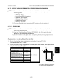
The polygon motor speed is as follows.
Resolution
400 dpi
600 dpi
391.2 dpi
406.4 dpi
Modes
Copy, Fax
Printer
Fax (image
rotation)
Fax (mm
printing)
Motor Speed (rpm)
NAD30S/
NAD40
NAD30
Approx. 14170 Approx. 18110
Approx. 21260 Approx. 27170
Approx. 14400 Approx. 18400
Approx. 13860
Approx. 17710
1 line cycle (µs)
NAD30S/
NAD40
NAD30
353
276
235
184
694
543
361
282
In previous models, the mirror speed increased for higher resolutions. However, for
this machine, the line cycle (time taken to output one main scan line of data to the
laser diode) varies also, so there is no simple relationship between resolution and
mirror speed.
2-22
26 March 1998
LASER EXPOSURE
2.3.2 OPTICAL PATH
[F]
[I]
[G]
[E]
Detailed
Descriptions
[D]
[B]
[C]
[A]
[H]
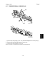
A231D501.WMF
The output path from the laser diode to the drum is shown above.
The LD unit [A] outputs two laser beams to the polygon mirror [B] through the
cylindrical lens [C] and the shield glass [D].
Each surface of the polygon mirror reflects two full main scan lines. The laser
beams go to the F-theta mirror [E], mirror [F], and BTL (barrel toroidal lens) [G].
Then these laser beams go to the drum through the toner shield glass [H].
The laser synchronizing detector [I] determines the main scan starting position.
2-23
LASER EXPOSURE
26 March 1998
2.3.3 AUTO POWER CONTROL (APS)
Front Cover Safety switch and
Upper Right Cover Switch
+5V
+5VLD
Error
Error
LEVEL1
LD
PD
VIDEO
LD1
PB
IC 2
REF1
VIDEO
LD
GAVD
(IC 7)
BICU
+5VLD
LDOFF
LD
VIDEO
PD
PB
LEVEL2
REF2
LD2
IC 3
LD
Error
LDDR
A231D502.WMF
IC2 and IC3 on the LDDR drive the laser diodes. Even if a constant electric current
is applied to the laser diode, the intensity of the output light changes with the
temperature. The intensity of the output decreases as the temperature increases.
In order to keep the output level constant, IC2 and IC3 monitor the current passing
through the photodiode (PD). Then they increase or decrease the current to the
laser diode as necessary, comparing it with the reference levels (REF1 and REF2).
This auto power control is done just after the machine is turned on and during
printing while the laser diode is active.
The reference levels are adjusted on the production line. Do not touch the variable
resistors on the LDDR in the field.
2-24
26 March 1998
LASER EXPOSURE
2.3.4 DUAL BEAM WRITING
[D]
[B]
[C]
Detailed
Descriptions
[E]
[A]
[D]
A230D203.WMF
This LD unit has two laser diodes; LD1 [A] and LD2 [B] for writing the image. This
means that each face of the polygon mirror writes two main scan lines, and twelve
main scans are produced when the polygon mirror rotates once. The reasons for
this mechanism are as follows.
1) To reduce the polygon motor rotation speed
2) To reduce the noise generated by the polygon motor
3) To reduce the frequency of the image data clock
Two laser beams are transferred to the polygon mirror [C] through collimating lens
[D] and prism [E]. The two laser beams arrive on the drum surface about 2 mm
away from each other in the main scan direction and about 0.06 mm (at 400 dpi) in
the sub scan direction (see the next page).
The reason for the two-mm difference in the main scan direction is so that the
machine can detect a laser synchronization signal for each beam.
2-25
LASER EXPOSURE
26 March 1998
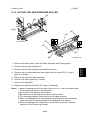
2.3.5 LASER BEAM PITCH CHANGE MECHANISM
2 mm
P1
P2
[B]
P1: 400 dpi
P2: 600 dpi
[D]
[C]
A230D204.WMF
[A]
A231D503.WMF
A printer option is available for this machine and the resolution of the printer is 600
dpi. The machine changes the resolution between 400 and 600 dpi by rotating the
LD unit.
When the LD positioning motor [A] turns, the metal block [B] (which contacts the
LD unit housing [C]) moves up and down. This changes the position of the L2 laser
beam (L1 does not move).
Both LD unit positions are at fixed distances from the LD home position sensor [D]
(measured by motor pulses). Usually, the LD unit moves directly to the proper
position. However, when the number of times that the resolution has changed
reaches the value of SP2-109-5, the LD unit moves to the home position (the home
position sensor activates), then it moves to the proper position. This recalibrates
the LD unit positioning mechanism.
2-26
26 March 1998
LASER EXPOSURE
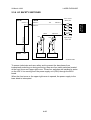
2.3.6 LD SAFETY SWITCHES
Front Cover
Safety Sw
LDDR
CN312-2
CN402-3
+5V
CN403-1
Detailed
Descriptions
BICU
CN402-4
-1
LD5V
LD2
CN403-3
Upper Right
Cover Sw
CN109-1
CN301-4
LD1
PSU
+5V
A232D500.WMF
To ensure technician and user safety and to prevent the laser beam from
inadvertently switching on during servicing, there are four safety switches located
at the front cover and upper right cover. These four switches are installed in series
on the LD5 V line coming from the power supply unit (PSU) through the BICU
board.
When the front cover or the upper right cover is opened, the power supply to the
laser diode is interrupted.
2-27
PHOTOCONDUCTOR UNIT (PCU)
26 March 1998
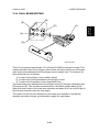
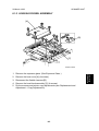
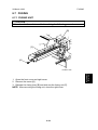
2.4 PHOTOCONDUCTOR UNIT (PCU)
2.4.1 OVERVIEW
1
2
3
9
4
8
5
7
6
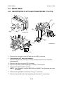
A230D301.WMF
The PCU consists of the components shown in the above illustration. An organic
photoconductor (OPC) drum (diameter: 60 mm) is used in this machine.
1. Toner Collection Coil
2. Toner Collection Plate
3. Spur
4. Pick off Pawl
5. OPC Drum
6. Transfer Entrance Guide
7. Charge Roller Cleaning Pad
8. Charge Roller
9. Cleaning Blade
2-28
26 March 1998
PHOTOCONDUCTOR UNIT (PCU)
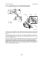
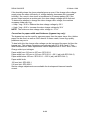
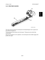
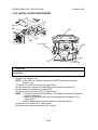
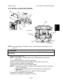
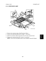
2.4.2 DRIVE MECHANISM
[C]
[E]
[B]
[D]
A230D302.WMF
The drive from the main motor [A] is transmitted to the drum [B] through a series of
gears, a timing belt [C], and the drum drive shaft [D]. The main motor has a drive
controller, which outputs a motor lock signal when the rotation speed is out of the
specified range.
The fly-wheel [E] on the end of the drum drive shaft stabilizes the rotation speed
(this prevents banding and jitter from appearing on copies).
The NAD40 has two flywheels because of the higher speed.
2-29
Detailed
Descriptions
[A]
DRUM CHARGE
26 March 1998
2.5 DRUM CHARGE
2.5.1 OVERVIEW
[F]
[D]
[E]
[C]
[A]
[B]
A231D525.WMF
This copier uses a drum charge roller instead of a scorotron corona wire to charge
the drum. The drum charge roller [A] always contacts the surface of the drum [B] to
give it a negative charge.
The high voltage supply board [C] gives a negative dc voltage to the drum charge
roller through the charge roller terminal [D], bias plate [E], and the rear roller
bushing [F]. This gives the drum surface a negative charge of –950V.
2-30
26 March 1998
DRUM CHARGE
2.5.2 CHARGE ROLLER VOLTAGE CORRECTION
Correction for Environmental Conditions
ID Sensor Pattern
3 cm
[A]
[B]
Sub Scan Direction
-1650 V (NAD40)
-1630 V (NAD30)
Charge Voltage
Laser Diode
On
Off
Drum Potential
-950 V
-600 V
-550 V
-380 V
-150 V
V sg (4.00 V)
V sdp (3.50 V)
Development Bias
ID Sensor Output
V sp (0.31 V)
t
A231D506.WMF
In the drum charge roller system, the voltage transferred from roller to drum varies
with the temperature and humidity around the drum charge roller. The lower the
temperature or humidity is, the higher the applied voltage required.
To compensate, the machine uses the ID sensor to measure the effects of current
environmental conditions. For this measurement, the process control parameters
are balanced so that any small change in drum potential caused by environmental
effects is reflected in a change in the amount of toner transferred to the drum.
This measurement is made immediately after the ID sensor pattern for toner
density control. Immediately after making ID sensor pattern [A], the charge roller
voltage drops so that drum potential is reduced to -600V. At the same time,
development bias goes back to -550V. The drum potential is now slightly higher
than the development bias, so only a very small amount of toner transfers to the
drum. The ID sensor measures the density of this pattern [B], and the output
voltage is known as Vsdp. This voltage is compared with Vsg (read from the bare
drum at the same time).
2-31
Detailed
Descriptions
3 cm 3 cm
DRUM CHARGE
26 March 1998
If the humidity drops, the drum potential goes up even if the charge roller voltage
supply stays the same (efficiency of voltage transfer decreases with increased
humidity). As a result, more toner is transferred to ID sensor pattern [B]. If the
sensor output reaches a certain point, the drum charge voltage will be reduced.
To determine whether to change the drum charge roller voltage, the machine
compares Vsdp with Vsg.
• Vsdp / Vsg > 0.90 = Reduce the drum charge voltage by 30 V
• Vsdp / Vsg < 0.85 = Increase the drum charge voltage by 30 V
NOTE: The minimum drum charge roller voltage is – 2 kV.
Correction for paper width and thickness (bypass tray only)
The bypass tray can be used for narrower paper than the paper trays. Also, thicker
paper can be used, as well as OHP sheets. In these cases, some copy quality
problems may occur.
To deal with this, the charge roller voltage can be increased for paper fed from the
bypass tray. The voltage corrections are adjusted with SP 2-914-1 and 2. The
width thresholds for these adjustments can be adjusted with 2-309-1 and 2-309-2.
Charge roller input voltages
Paper width from 216 mm to 297 mm: SP2-001-1
Paper width from 150 mm to 216 mm: SP2-001-1 + 50 V (adj. with SP2-914-2)
Paper width below 150 mm: SP2-001-1 + 250 V (adj. with SP2-914-1)
Paper width limits
150 mm limit: SP2-309-1
216 mm limit: SP2-309-2
Similar voltage adjustments are available for development bias and transfer
current.
2-32
26 March 1998
DRUM CHARGE
2.5.3 ID SENSOR PATTERN PRODUCTION TIMING
ID sensor pattern
Vsp/Vsg
2
3
8
9
10
1
2
3
........
12 13 14 15
........
Series of copies
Vref Decision
New Vref Decision
New Vref Decision
A231D535.WMF
An ID sensor pattern is made during the machine initialization (after the main
power switch or operation switch is turned on) and after finishing a copy job in
which 10 (this is the default value) or more copies were made.
2.5.4 DRUM CHARGE ROLLER CLEANING
[C]
[D]
[B]
[A]
A230D303.WMF
Because the drum charge roller [A] always contacts the drum, it gets dirty easily.
So, the cleaning pad [B] also contacts the drum charge roller all the time to clean
the surface of the drum charge roller.
The pin [C] at the rear of the cleaning pad holder touches the cam gear [D], and
this gear moves the cleaning pad from side to side. This movement improves the
cleaning.
2-33
Detailed
Descriptions
1
ID sensor pattern
Vsp/Vsg
DEVELOPMENT
26 March 1998
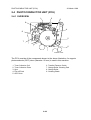
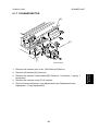
2.6 DEVELOPMENT
2.6.1 OVERVIEW
7
1
6
2
3
5
A230D401.WMF
4
This machine uses a single-roller development system. A dual mixing roller
mechanism is used for developer mixing.
1. Drum
2. Development Roller
3. Paddle Roller
4. TD Sensor
5. Mixing Auger
6. Development Filter
7. Doctor Blade
2-34
26 March 1998
DEVELOPMENT
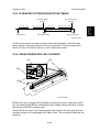
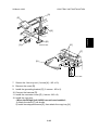
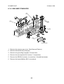
2.6.2 DRIVE MECHANISM
Detailed
Descriptions
[A]
[B]
[C]
A230D402.WMF
The main motor [A] drives the development roller [B] through a train of gears and
the paddle roller gear [C].
The development drive gears are helical gears. These gears are quieter than
normal gears.
When the development unit is pushed in, the development drive shaft engages the
paddle roller gear.
2-35
DEVELOPMENT
26 March 1998
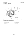
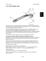
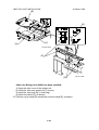
2.6.3 DEVELOPER MIXING
[B]
[C]
[A]
[D]
[C]
[C]
A230D403.WMF
This mechanism supplies toner from the toner bottle to the development roller.
The dual mixing roller consists of the outer paddle [A] and the inner auger [B]. The
outer paddle moves developer to the front and supplies it to the development
roller. The developer that is spilt off by the doctor blade goes through the holes
[C] in the outer paddle, and is transported towards the rear by the inner auger.
While the dual mixing roller is moving the developer, some developer also goes
back to the development unit through the holes in the bottom of the paddle roller
.
New toner from the toner bottle and recycled toner from the toner collection coil
both enter the development unit at the top [D]
2-36
26 March 1998
DEVELOPMENT
2.6.4 DEVELOPMENT BIAS
[A]
[B]
[C]
A230D404.WMF
This machine uses a negative-positive development system, in which black areas
of the latent image are at a low negative charge (about -150 V) and white areas are
at a high negative charge (about -950 V).
To attract negatively charged toner to the black areas of the latent image on the
drum, the high voltage supply board [A] applies a bias of -600 volts to the
development roller throughout the image development process. The bias is applied
to the development roller shaft [B] through the bias terminal spring [C] and bias
terminal [D].
The development bias voltage (-600 V) can be adjusted with SP2-201.
Correction for paper width and thickness (bypass tray only)
The bypass tray can be used for narrower paper than the paper trays. Also, thicker
paper can be used, as well as OHP sheets. In these cases, some copy quality
problems may occur.
To deal with this, the development bias can be increased for paper fed from the
bypass tray. The voltage corrections are adjusted with SP 2-914-3 and 4. The
width thresholds for these adjustments can be adjusted with 2-309-1 and 2-309-2.
Development bias voltages
Paper width from 216 mm to 297 mm: SP2-201-1
Paper width from 150 mm to 216 mm: SP2-201-1 + 50 V (adj. with SP2-914-4)
Paper width below 150 mm: SP2-201-1 + 200 V (adj. with SP2-914-3)
Paper width limits
150 mm limit: SP2-309-1, 216 mm limit: SP2-309-2
Similar voltage adjustments are available for charge roller input voltage and
transfer current.
2-37
Detailed
Descriptions
[D]
DEVELOPMENT
26 March 1998
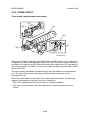
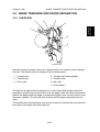
2.6.5 TONER SUPPLY
Toner bottle replenishment mechanism
[F]
[G]
[H]
[D]
[C]
[E]
[A]
[B]
A231D504.WMF
When a toner bottle is placed in the bottle holder unit [A] and the unit is pushed in
completely, pin [B] moves against the side [C] of the PCU, and the toner shutter [D]
is pulled out to open the bottle. When the toner bottle holder lever [E] is put back in
the original position, the cap [F] on the toner bottle is pulled away and kept in place
by the chuck [G].
The toner supply mechanism transports toner from the bottle to the development
unit. The toner bottle has a spiral groove [H] that helps move toner to the
development unit.
When the bottle holder unit is pulled out to add a new toner bottle, the following
happens automatically to prevent toner from scattering.
• The chuck releases the toner bottle cap into its proper position.
• The toner shutter shuts to block the opening as a result of pressure from a
spring.
2-38
26 March 1998
DEVELOPMENT
Toner supply mechanism
[A]
[C]
A231D505.WMF
A230D452.WMF
[D]
[E]
The toner supply motor [A] drives the toner bottle [B] and the mylar blades [C].
First, the toner falls down into the toner bottle holder. The toner supply mylar
blades transfer the toner to the slit [D]. When the PCU is installed into the machine,
the shutter [E] under the PCU is opened by the development unit. Then the toner
falls down into the development unit through the slit and the shutter.
2-39
Detailed
Descriptions
[B]
DEVELOPMENT
26 March 1998
2.6.6 TONER DENSITY CONTROL
Overview
There are two modes for controlling toner supply: sensor control mode and image
pixel count control mode. The mode can be changed with SP2-208-1. The factory
setting is sensor control mode. Image pixel count mode should only be used if the
TD or ID sensor is defective.
Toner Density Control Flow Chart
Copying
Image pixel count
Vt(10) detection
Has the following
condition been detected
20 times?
Vtref < Vt(10)
No
Yes
No
Has the following
condition been detected 10
times?
Vtref-0.2 > Vt(10)
or Has the toner supply
motor been
turned on ?
Vtref + 0.1 < Vt(10)
or
K ≥ 1.5 ?
Yes
K = K - 0.25
K = K - 0.5
No
Yes
K not
changed
K = K + 0.25
Toner supply motor
turns on in reverse for
0.3 s.
GAIN determination
Image pixel count mode:
GAIN = 1
Toner supply motor on
time calculation
No
Have 10 or
more copies been
made since the last Vtref
change and is the
copy job
finished?
Vsp/Vsg detection
Yes
New Vtref determination
A231D540.WMF
2-40
26 March 1998
DEVELOPMENT
In sensor control mode, the machine varies toner supply for each copy, to maintain
the correct proportion of toner in the developer and to account for changes in drum
reflectivity over time. The adjustment depends on two factors
• The amount of toner required to print the page (based on a black pixel amount
for the page)
• Readings from the TD sensor and ID sensor
Each step of the previous flow chart is explained in more detail on the following
pages.
Toner density sensor initial setting
When new developer with the standard toner concentration is installed (12.5 g of
toner in 500 g of developer, which is 2.5% by weight), TD sensor initial setting must
be done using SP2-801. This sets sensor output to 4.0V. This value will be used as
the toner supply reference voltage (Vtref) of the TD sensor.
Image pixel count
The CPU adds up the image data value of each pixel and converts the sum to a
value between 0 and 255. (The value would be 255 if the page was completely
black.)
Vt(10) detection
The toner density in the developer is detected once every copy cycle. The sensor
output voltage Vt(10) is the average of the 10 most recent sensor output voltage
readings.
Toner density measurement
The machine compares Vt(10) and Vtref. If Vt(10) is greater than Vtref, the toner
concentration in the development unit is low and more toner should be added.
When Vt(10) > Vtref has been detected 20 times (toner concentration is
consistently low), 0.1 is added to Vref, and the conditions are checked again. The
result decides the value of “K” (toner supply rate coefficient), which is one of the
factors in the toner supply motor on time calculation.
If Vt(10) > Vtref has not been detected 20 times, 0.2 is subtracted from Vtref, and
“K” is decided in a similar way as for the previous condition.
GAIN determination
GAIN is another factor in the toner supply motor on time calculation. It is decided
using the following data.
• Vtref – Vt(10)
• Ten most recent Vt values
2-41
Detailed
Descriptions
Sensor Control Mode
DEVELOPMENT
26 March 1998
Toner supply motor on time calculation
The toner supply motor on time is decided using the following formula:
L
(Vt - Vtref) x 10,000 O
0.7mg/cm 2 x Image Pixel Count x Gain
M
P............(1)
+
Toner Supply Rate x K P
Toner Supply Rate x K
M
N
Q
(255 - Image Pixel Count) Gain O
L
......................................................(2)
x
x
P
M
255
6
Q
N
NOTE: 1) The toner supply rate can be changed using SP2-209.
2) K = Toner supply rate coefficient (0.25 ~ 3.0: default = 3.0).
3) The bracket (2) in the above formula is only used if Vtref < Vt.
4) The maximum toner supply motor on time is 1.2 s.
Vsp and Vsg detection
The ID sensor (at the lower right area of the drum) detects the following voltages.
• Vsg: The ID sensor output when checking the drum surface.
• Vsp: The ID sensor output when checking the ID sensor pattern.
In this way, the reflectivity of both the drum surface and the pattern on the drum are
checked. This compensates for any variations in the reflectivity of the pattern on
the drum or the reflectivity of the drum surface.
The ID sensor pattern is made on the drum by the charge roller and laser diodes.
Vsg/Vsp is detected every 10 copies to decide the new Vtref. The Vsg/Vsp
detection period can be changed using SP2-210 (the default is 10).
New Vtref determination
Even if the toner concentration in the developer is kept constant by checking the
TD sensor, the toner potential (chargeability) and the image density both change
with humidity and the amount of toner on the carrier. Therefore, the actual image
density, using the ID sensor output, is also used as one of the factors for deciding
the new Vtref which is used for toner density control.
The new Vtref is determined using the following data.
• Vtref – Vt(10)
• Vsp/Vsg
From this point, toner density control is done using the new Vtref.
Image Pixel Count Control Mode.
This mode should only be used as a temporary measure while waiting for
replacement parts, such as a TD sensor. This mode controls the toner supply
amount using the same formula for the toner bottle motor on time. However, the
GAIN value is fixed at 1, and the other coefficients, such as “K”, “toner supply rate”
keep the values that they had when the toner density control mode was changed
over to image pixel count mode.
2-42
26 March 1998
DEVELOPMENT
2.6.7 TONER NEAR END/END DETECTION
Toner near end/end detection flow chart
Detailed
Descriptions
Start copying (each page)
Vt(10) detection
Vtref - Vt(10) ≤ –0.45
No
Has Vtref ≤ Vt(10)
been detected 40
times?
Yes
No
Yes
K = 0.25
Toner supply motor on
time x2
Toner near-end
Has
Vtref ≤ Vt(10)
been detected 20
more times?
Toner supply motor turns
while main motor turns
No
Yes
Toner near-end
Has Vtref ≤ Vt(10)
been detected 40
times?
Yes
ID sensor
check: Vsp ≤ 2.0 V?
Toner supply motor turns
while main motor turns
No
Yes
Yes
No
Has
Vtref ≤ Vt(10)
been detected 20
more times?
No
Have 90 copies
been made since toner
near-end detection?
Yes
Toner end
A231D538.WMF
2-43
DEVELOPMENT
26 March 1998
Toner near end is detected using the TD sensor output data.
If Vtref-Vt(10) is less than or equal to -0.45, the toner concentration is very low. “K”
becomes 0.25 and the machine enters the toner near end condition. Then, the
toner supply motor turns on to supply toner.
If Vtref-Vt(10) is greater than -0.45, the toner concentration is still not terribly low,
but the machine does further tests by comparing Vtref and Vt(10). If the machine
has detected 40 times that Vt(10) is greater than Vtref, the toner supply motor turns
on for double the time that it would be with the previous formula. If the toner
concentration is still low, the machine enters the toner near end condition.
Toner end is detected using the ID sensor.
If Vsp is less than 2.0V, the density of the ID sensor pattern is very light, so the
machine detects a toner end condition. However, if Vsp stays bigger than 2.0V but
90 copies have been made after toner near end was determined, the machine
enters the toner end condition.
The number of copies between toner near-end and toner end can be changed with
SP2-213. The default is 90.
2-44
26 March 1998
DEVELOPMENT
2.6.8 TONER END RECOVERY
Toner end recovery flow chart
Cover switch off/on?
Detailed
Descriptions
Toner end or
Toner near end
No
Yes
Toner supply motor turns
on and Vtp detection
Is the toner
concentration low?
No
Toner supply motor turns
on for 10 s
Yes
Vt detection
No
Has the
toner supply motor been
turned on 20
times?
No
Vtref - Vt > 0?
Yes
Yes
Vtp' detection
Toner supply motor turns
on for 2 s.
Is the toner
concentration
still low?
No
Has the
motor turned on 8
times?
Yes
No
Is this the 4th
Vtp' detection?
Yes
Toner End
Clear the toner end/nearend condition and reset
the value of "K" to 3.0.
A231D539.WMF
2-45
DEVELOPMENT
26 March 1998
If the front cover is opened and closed while a toner near end/end condition exists,
the machine will attempt to recover using measurements from the TD sensor.
When the front cover is closed, the toner supply motor turns on to supply toner.
The machine checks the TD sensor output 2 s after the main motor turns on. This
is called Vtp. It is checked again every 1 s, and these values are called Vtp’.
The machine detects the toner concentration using Vtref, Vt(10), Vtp, and Vtp’. If
the toner concentration is still too low, the toner supply motor turns on for another
10s. Then, the machine checks Vt. If toner concentration is at the standard level,
the toner near end/end condition is cancelled and “K” is reset. If toner
concentration has not reached the standard level, the toner supply motor rotates
continuously until it does (maximum motor on time is 16s).
2.6.9 TONER SUPPLY IN ABNORMAL SENSOR CONDITIONS
The TD sensor is checked every copy. If the readings from the TD sensor become
abnormal during a copy job, the machine holds the GAIN factor constant (GAIN is
normally calculated from TD sensor readings) to allow toner supply to vary with
only pixel count for the rest of the copy job. Then at the end of the copy job, an SC
code is generated and the machine must be repaired.
The ID sensor is checked every 10 copies. If readings become abnormal, an SC
code is generated and the machine must be repaired. If this happens during a copy
job, Vtref is not changed, the copy job is allowed to finish, and then the SC code is
generated.
If spare parts are not available, the technician can use SP 2-208-1 to temporarily
put the machine in image pixel count mode.
Details of how the machine determines an abnormal sensor detection are in
section 7 (Troubleshooting).
2-46
26 March 1998
DRUM CLEANING AND TONER RECYCLING
2.7 DRUM CLEANING AND TONER RECYCLING
2.7.1 DRUM CLEANING
[D]
Detailed
Descriptions
[E]
[A]
[B]
[C]
[A]
A231D507.WMF
The cleaning blade [A] removes any toner remaining on the drum after the image is
transferred to the paper. This model uses a counter blade system.
The toner remaining on the drum is scraped off by the cleaning blade, and is
transferred to the toner collection coil [B] by the toner collection plate [C].
The collar [D] on the cleaning blade bracket contacts the outer rim of cam gear [E],
and this gear moves the cleaning blade from side to side. (This gear is the same
cam gear that moves the charge roller cleaning pad from side to side.) This
movement helps to disperse spots of accumulated toner to prevent early blade
edge wear at any particular location.
To remove the toner and other particles that are accumulated at the edge of the
cleaning blade, the drum turns in reverse for about 5 mm at the end of every copy
job.
2-47
DRUM CLEANING AND TONER RECYCLING
26 March 1998
2.7.2 TONER RECYCLING
[A]
[C]
A230D452.WMF
[B]
Toner which is transferred to the toner collection coil [A] is transported to the
opening [B] in the bottom of the PCU. Then, this toner falls into the development
unit with new toner coming from the toner bottle and it is all mixed together by the
paddle roller [C].
2-48
26 March 1998
PAPER FEED
2.8 PAPER FEED
2.8.1 OVERVIEW
2
3
4
5
6
7
8
9
10
11
A230D701.WMF
14
13
12
There are two paper trays, each of which can hold 500 sheets.
The paper tray feed stations use an FRR system.
There are two relay sensors, one just above each set of relay rollers. These
sensors are used for paper jam detection.
The components of the paper feed section are as follows.
There are no paper size sensors. The user inputs the paper size with a UP mode.
1.
2.
3.
4.
5.
6.
7.
Upper Tray Set Sensor
Upper Pick-up Roller
Upper Paper Height Sensor
Upper Paper Feed Roller
Upper Relay Sensor
Upper Relay Roller
Upper Separation Roller
8. Lower Relay Sensor
9. Lower Relay Roller
10. Lower Paper Feed Roller
11. Lower Separation Roller
12. Lower Pick-up Roller
13. Lower Paper Height Sensor
14. Lower Tray Set Sensor
2-49
Detailed
Descriptions
1
PAPER FEED
26 March 1998
2.8.2 PAPER FEED DRIVE MECHANISM
[A]
[B]
[C]
A231D508.WMF
The main motor [A] drives the pick-up and feed mechanism of both the upper and
second paper feed stations through gears and the paper feed clutches [B].
When the paper tray is inside the machine, the pick-up roller always contacts the
top sheet of the paper stack (see Pick-up and Separation Roller Release
Mechanism for more detail). When the paper feed clutch turns on, the pick-up
roller, paper feed roller, and separation roller start rotating to feed the paper. The
paper feed clutch stays on until shortly after the registration sensor [C] has been
activated.
2-50
26 March 1998
PAPER FEED
2.8.3 PICK-UP AND SEPARATION ROLLER RELEASE
MECHANISM
Detailed
Descriptions
[E]
[A]
[D]
A230D703.WMF
[C]
[E]
[A]
[B]
A230D704.WMF
When the paper tray [A] is not inside the machine, the separation roller [B] is away
from the paper feed roller [C] and the pick-up roller [D] stays in the upper position.
When the paper tray is set into the machine, it pushes the release lever [E]. This
causes the pick-up roller [D] to go down and the separation roller [B] to move up
and contact the paper feed roller.
2-51
PAPER FEED
26 March 1998
2.8.4 PAPER LIFT MECHANISM
[E]
[D]
[H]
[A]
[F]
[G]
[C]
[B]
A230D702.WMF
The paper tray sensor [A] detects when the paper tray [B] is placed in the machine.
When the machine detects that the paper tray is in the machine, the tray lift motor
[C] rotates and the coupling gear [D] on the tray lift motor engages the pin [E] on
the lift arm shaft [F]. Then the tray lift arm [G] lifts the tray bottom plate [H].
2-52
26 March 1998
PAPER FEED
[C]
Detailed
Descriptions
[B]
[A]
A231D526.WMF
When the paper tray is placed in the machine, the pick-up roller [A] lowers. When
the top sheet of paper reaches the proper height for paper feed, the paper pushes
up the pick-up roller, and the actuator [B] on the pick-up roller supporter activates
the paper height sensor [C] to stop the tray lift motor.
After several paper feed cycles, the paper level gradually lowers and the paper
height sensor is de-activated. The tray lift motor turns on again until this sensor is
activated again.
When the tray is drawn out of the machine, the tray lift motor coupling gear
disengages the pin on the lift arm shaft, and the tray bottom plate then drops under
its own weight.
2-53
PAPER FEED
26 March 1998
2.8.5 PAPER END DETECTION
[B]
[A]
[C]
A230D706.WMF
If there is some paper in the paper tray, the paper end feeler [A] is raised by the
paper stack and the paper end sensor [B] is deactivated.
When the paper tray runs out of paper, the paper end feeler drops into the cutout
[C] in the tray bottom plate and the paper end sensor is activated.
2-54
26 March 1998
PAPER FEED
2.8.6 PAPER REGISTRATION
[B]
[C]
A230D705.WMF
Main motor [A] rotation is transmitted to the registration clutch gear [B] (located on
the lower registration roller shaft) through a train of gears.
The registration sensor [C] is positioned just before the registration rollers.
When the paper leading edge activates the registration sensor, the registration
clutch is off and the registration rollers are not turning. However, the relay clutch [E]
stays on for a bit longer. This delay allows time for the paper to press against the
registration rollers and buckle slightly to correct skew. Then, the registration clutch
energizes and the relay clutch re-energizes at the proper time to align the paper
with the image on the drum. The registration and relay rollers feed the paper to the
image transfer section.
The registration sensor is also used for paper misfeed detection.
2-55
Detailed
Descriptions
[A]
PAPER FEED
26 March 1998
2.8.7 PAPER FEED AND JAM TIMING
NAD40: From 2nd Paper Tray (A4 sideways)
0
1000
2000
3000
ms
Main Motor
Relay Clutch
T1
Paper Feed Clutch
T1
J1
J2
Lower Relay Sn.
J1
J2
Upper Relay Sn.
T2
J1
J2
Registration Sn.
T3
F-gate Signal
Registration
Clutch
T4
A231D537.WMF
T1. The relay clutch and paper feed clutch turn on 500 ms after the main motor
turned on.
T2. The relay clutch and paper feed clutch turn off 138 ms after the registration
sensor turned on.
T3. The relay clutch and paper feed clutch turn on again and the registration clutch
turns on 186 ms after the F-gate signal (laser main scan writing start) has been
activated.
T4. The registration clutch turns off 150 ms after the registration sensor turned off.
J1. Checks whether the sensors are activated within 0.38 s (35 cpm machine) or
0.3 s (45 cpm machine) after the designated time for these sensors.
J2. Checks whether the sensors are deactivated within 0.38 s (35 cpm machine) or
0.3 s (45 cpm machine) after the designated time for these sensors.
2-56
26 March 1998
IMAGE TRANSFER AND PAPER SEPARATION
2.9 IMAGE TRANSFER AND PAPER SEPARATION
2.9.1 OVERVIEW
1
2
3
Detailed
Descriptions
4
7
5
6
A230D501.WMF
Instead of using a transfer corona or a transfer roller, this machine uses a transfer
belt unit. The transfer belt unit consists of the following parts.
1. Contact lever
4. Transfer belt cleaning blade
2. Transfer belt
5. Transfer roller
3. Drive roller
6. Idle roller
7. Pick-off pawl
The belt has a high electrical resistance, so it can hold a high positive electrical
potential to attract toner from the drum onto the paper. Also, the electrical potential
attracts the paper itself and helps to separate the paper from the drum and to carry
the paper upwards. The pick-off pawl ensures that the paper separates from the
drum.
The transfer belt cleaning blade removes toner from the transfer belt to prevent the
back side of the paper from being stained.
2-57
IMAGE TRANSFER AND PAPER SEPARATION
26 March 1998
2.9.2 BELT DRIVE MECHANISM
[A]
[C]
[D]
[B]
A231D509.WMF
The main motor [A] drives the transfer belt [B] through a train of gears, the belt
contact clutch [C], and the drive roller gear [D].
2.9.3
IMAGE TRANSFER AND PAPER SEPARATION
MECHANISM
The image is transferred from the drum in the following steps.
[C]
1. The registration clutch turns on to feed the
paper [A] at the correct time to synchronize
the leading edge of the developed latent
image on the drum [B] with the leading edge
of the paper. The transfer belt [C] is away
from the drum at this time.
[B]
A231D522.WMF
[A]
2-58
26 March 1998
IMAGE TRANSFER AND PAPER SEPARATION
Detailed
Descriptions
2. The transfer belt contact clutch turns on a
certain time after the main motor started.
Then, the transfer belt moves into contact
with the drum.
A231D523.WMF
3. When the paper enters the gap between the
belt and the drum, the high voltage supply
board [A] applies a high positive current to
the belt to transfer the image to the paper.
I1 = It + I2
[A]
A231D521.WMF
4. After receiving the image from the drum, the paper is fed by the belt.
5. The paper moves to the end of the transfer belt unit, where it separates from
the belt as the belt curves away. Then, the paper goes to the fusing unit.
2-59
IMAGE TRANSFER AND PAPER SEPARATION
26 March 1998
2.9.4 TRANSFER BELT UNIT CONTACT MECHANISM
[A]
[E]
[B]
[C]
[D]
[D]
A230D503.WMF
The belt contact and release mechanism consists of the belt contact clutch [A],
cam [B], and contact lever [C].
The belt contact clutch turns on and the cam with the clutch rotates half of a
complete rotation. The contact lever, riding on the cam, is lifted up and the spring
[D] pushes the belt into contact with the drum.
The transfer belt contact home position sensor [E] is used to detect the home
position of the cam (this is when the belt is away from the drum).
The belt must be released from the drum between copy jobs. The reasons are as
follows.
• To prevent the ID sensor pattern on the drum from being rubbed off by the
transfer belt.
• To prevent a change in the drum’s characteristics because of the influence of
additives inside the rubber belt.
2-60
26 March 1998
IMAGE TRANSFER AND PAPER SEPARATION
2.9.5 TRANSFER BELT CHARGE
Overview
[C]
[A]
Detailed
Descriptions
[B]
[D]
[E]
A230D504.WMF
The high voltage supply board [A] applies the positive transfer belt current to the
transfer belt [B] through the terminal block [C], terminal plate [D], and the roller [E].
The terminal block and the terminal plate contact each other when the right cover is
closed.
The high voltage supply board adjusts the current to the roller to keep a small but
constant current flow to ground through the belt, paper, and drum. If this current is
not kept constant, efficiency of toner transfer and paper separation will vary with
paper thickness, type, environmental condition, or changes in transfer belt surface
resistance.
2-61
IMAGE TRANSFER AND PAPER SEPARATION
26 March 1998
Correction for paper width and thickness
SP2-309-1
Default: 150 mm
0
SP2-309-2
Default: 216 mm
297 mm
Paper Tray
SP2-309-3
Current x 1.2
SP2-309-4
Current x 1.2
Current x 1.0
By-pass Tray
SP2-309-5
Current x 1.5
SP2-309-6
Current x 1.5
Current x 1.0
A231D541.WMF
To counteract the effects of paper width and thickness, a range of SP modes are
available.
For paper width, there are two thresholds. The factory settings are 150 and 216
mm. Below 216 mm, the transfer current can be increased (by default, it is
multiplied by 1.2 for the main body paper trays). Below 150 mm, the transfer
current can be set even higher, although by default it is kept the same as the
current for below 216 mm. The higher current allows for the fact that current prefers
to go to the drum from the belt directly, and not through the paper, which leads to
insufficient toner transfer for narrow paper widths.
For thickness, it is assumed that the user will use thicker paper from the bypass
tray, so separate settings are available for this tray. By default, the current for
paper narrower than 216 mm is 1.5 times the normal current.
The drawing shows the SP modes which control these currents.
Currents applied to leading edge and image areas
The transfer current can also be different for the leading edge and the image area.
There are separate adjustments for bypass feed for this also. The timing for
starting to apply leading edge current, for the switchover from leading edge current
to image area current, and for switching off at the trailing edge can also be
changed.
Transfer current SP modes
- Image areas Paper trays: Side 1, SP2-301-1; Side 2, SP2-301-2
Bypass: SP2-301-4
Leading edge areas
Paper trays: SP2-301-3, Bypass: SP2-301-5
- Timing Leading edge start: SP2-911-1
Switchover to image area: SP2-911-2
Image area end (trailing edge): SP2-911-3
2-62
26 March 1998
IMAGE TRANSFER AND PAPER SEPARATION
[A]
[C]
[B]
A231D524.WMF
The cleaning blade [A] always contacts the transfer belt. It scrapes off any toner
and paper dust remaining on the belt.
To remove toner and other particles that are accumulated at the edge of the
cleaning blade, the transfer belt turns in reverse at the end of every copy job, in the
same way as the drum cleaning blade mechanism.
The toner and paper dust that is scraped off falls down into the toner collection
tank [B], which is in the transfer belt unit. This toner is not recycled.
When the toner overflow sensor [C] in the transfer belt unit detects a toner overflow
condition, the toner overflow indicator is lit. After this condition, 999 copies can be
made before operation is disabled.
2-63
Detailed
Descriptions
2.9.6 TRANSFER BELT CLEANING MECHANISM
IMAGE FUSING AND PAPER EXIT
26 March 1998
2.10 IMAGE FUSING AND PAPER EXIT
2.10.1 OVERVIEW
3
2
1
4
14
5
6
13
7
12
8
11
A231D514.WMF
10
9
This fusing unit contains pressure roller strippers [6]. These prevent the paper from
wrapping around the pressure roller (which is possible for a vertical paper transport
mechanism).
The fusing unit and paper exit area consist of the following parts.
1. Paper exit roller
8. Cleaning roller
2. Fusing exit sensor
9. Entrance guide
3. Junction gate
10. Hot roller
4. Transport roller (NAD30 and
NAD40 only)
11. Fusing lamp(s) (see the note)
5. Pressure spring
13. Thermofuse
6. Pressure roller strippers
14. Hot roller strippers
12. Thermistor
7. Pressure roller
NOTE: For 115V machines: One lamp is used.
For 230V machines: Two lamps are used.
2-64
26 March 1998
IMAGE FUSING AND PAPER EXIT
2.10.2 FUSING DRIVE AND RELEASE MECHANISM
Detailed
Descriptions
[B]
[A]
[G]
[F]
A230D604.WMF
[C]
[E]
[D]
A230D605.WMF
The main motor [A] drives the fusing unit through a train of gears and drives the
paper exit rollers through a gear and a timing belt [B].
The fusing unit drive release mechanism automatically disengages the fusing unit
drive gear [C] when the right cover [D] is opened. This allows the fusing unit drive
gear to rotate freely so that misfed paper can be easily removed.
When the right cover is opened, the actuator plate [E] pulls release wire [F]. The
wire pulls the fusing drive gear bracket [G] and the fusing unit drive is disengaged.
2-65
IMAGE FUSING AND PAPER EXIT
26 March 1998
2.10.3 FUSING ENTRANCE GUIDE SHIFT MECHANISM
[C]
[B]
A230R608.WMF
[A]
The entrance guide [A] for this machine has two holes on each side to adjust for
paper thickness, to prevent creasing. Normally, the right screw hole [B] on each
side is used.
For thin paper, move the entrance guide to the right by securing it with screw holes
[C]. This slightly lengthens the paper path which prevents the paper from creasing
in the fusing unit.
For thick paper, move the entrance guide to the left (use screw holes [B]). This
setting allows more direct access to the gap between the hot and pressure rollers.
This prevents thick paper from buckling against the hot roller, which can cause
blurring at the leading edge of the copy. Also, thick paper does not bend as easily,
and is therefore less prone to creasing.
2-66
26 March 1998
IMAGE FUSING AND PAPER EXIT
2.10.4 PRESSURE ROLLER
[B]
[A]
Detailed
Descriptions
[D]
[E]
[C]
A230D603.WMF
The pressure springs [A] constantly apply pressure between the hot roller [B] and
the pressure roller [C].
The pressure can be changed by adjusting the position of the pressure springs.
The left position [D] is the normal setting. The right position [E] increases the
pressure and this prevents insufficient fusing by the fusing unit.
2.10.5 CLEANING MECHANISM
[B]
[A]
A231D515.WMF
The cleaning roller [A] is always in contact with the pressure roller [B]. It collects
toner and paper dust adhering to the surface of the pressure roller. This is because
the cleaning roller is made of metal and collects adhering matter more easily than
the pressure roller (which has a teflon coating).
2-67
IMAGE FUSING AND PAPER EXIT
26 March 1998
2.10.6 FUSING TEMPERATURE CONTROL
A231D518.WMF
Temperature Control
There are two types of control: on/off control, and phase control. The mode can be
selected with SP1-104.
When the main power switch turns on, the CPU checks the ac frequency for 500
ms; this is done in case phase control mode is selected later. Then the CPU turns
on the fusing lamp. When the thermistor detects the stand-by temperature (155°C
for NAD30/NAD30S, 175°C for NAD40), the machine can start to print. When the
thermistor detects the operating temperature (165°C for NAD30/NAD30S, 185°C
for NAD40), the CPU turns the fusing lamp off/on to maintain this temperature.
Fusing Idling
If copies are not sufficiently fused soon after the main power switch is turned on,
fusing idling should be enabled with SP1-103. When fusing idling is enabled, it is
done when the temperature reaches the value of SP1-105-1 (Fusing temperature
adjustment) - 20°C
However, even if fusing idling is enabled, it is not done when the temperature at
power-up > the value of SP1-105-1 -20°C
In the opposite case, even if fusing idling is disabled, it is done when the
temperature at power-up ≤ 15°C
The fusing idling time is as follows.
The temperature at
power-up
15°C or less
Higher than 15°C
Fusing idling mode
Disabled
Enabled
30 s
2 min *
Not performed
30 s
* In this case, fusing idling also prevents dirty background.
2-68
26 March 1998
IMAGE FUSING AND PAPER EXIT
2.10.7 OVERHEAT PROTECTION
Even if the thermistor overheat protection fails, there is a thermofuse in series with
the common ground line of the fusing lamp. If the temperature of the thermofuse
reaches 169°C, the thermofuse opens, removing power from the fusing lamp. At
the same time, the copier stops operating. At this time, SC542 will be generated.
2-69
Detailed
Descriptions
If the hot roller temperature becomes greater than 230°C, the CPU cuts off the
power to the fusing lamp. At the same time, SC543 will be generated.
ENERGY SAVER MODES
26 March 1998
2.11 ENERGY SAVER MODES
2.11.1 OVERVIEW
Main Power
Switch Off
Any Status
Main Power
Power Off
Main Power
Switch On
Operation
Switch On
Main Power
Operation
Within
40~45s
to return
Operation
Switch On
Operation
Stand-by Mode
Auto off
Timer
Energy
Saver Key
Ringing
Signal
Fusing lamp Off
Energy Saver LED Off
System 5V Off
+5VE On
Low
Power
Timer
Energy
Saver
Key
Selected by
UP mode
Energy Saver Mode
Energy Saver Level 1 or 2
Fusing lamp to low temp.
Energy Saver LED On
System 5V On
Night Mode
Within 3s or
10s to
return
Low Power
Shift Timer
Low Power Mode
Fusing lamp to low
temp.
Energy Saver LED On
System 5V On
Operation
Operation
Switch Off
Operation
Auto Off Mode
System 5V Off
+5VE On
Within 20s
or 30s to
return
-Ringing
Signal
-Offhook
Fax ready
conditions
Operation
Switch Off
Operation
Night Standby Mode
System 5V On
Operation
Switch Off
A231D517.WMF
When the machine is not used, the energy saver function reduces power
consumption by decreasing the fusing temperature.
This machine has four types of energy saver mode as follows.
1) Energy saver mode
2) Low power mode
3) Auto off mode (copier configuration only)
4) Night mode (copier/fax configuration only)
These modes are controlled by the following UP and SP modes.
• Low power timer
• Low power shift timer
• Auto off timer
• Energy saver mode
• Auto off disabling (SP mode only)
The way that the machine operates depends on the combination of installed
equipment (copier only, copier/fax).
2-70
26 March 1998
ENERGY SAVER MODES
2.11.2 ENERGY SAVER MODE
Entering the energy saver mode
The machine enters energy saver mode when one of the following is done.
• The Clear Mode/Energy Saver Key is held down for a second (see Note).
• The low power timer runs out after the end of a job.
NOTE: The machine enters either energy saver mode or low power mode
when pressing the Clear Mode/Energy Saver key depending on the
setting of the UP mode.
What happens in energy saver mode
When the machine enters energy saver mode, the fusing lamp drops to a certain
temperature, depending on the energy saver level (see the table below) and the
operation panel indicators are turned off except for the Energy Saver LED and the
Power LED.
If the CPU receives the image print out command from an application (e. g. to print
incoming fax data or to print data from a PC), the fusing temperature rises to print
the data. However, the operation indicators stay off.
Return to stand-by mode
If one of the following is done, the machine returns to stand-by mode:
• The Clear Mode/Energy Saver Mode key is pressed
• Any key on the operation panel is pressed
• An original is placed in the ADF
• The ADF is lifted
• A sheet of paper is placed in the by-pass feed table
The recovery time from energy saver level 1 is about 3 s.
The recovery time from energy saver level 2 is about 10 s.
Operation
Switch
Energy
Saver
LED
Energy Saver
Level 1
On
On
Energy Saver
Level 2
On
On
Mode
Fusing Temp.
35 cpm: 157 °C
45 cpm: 175 °C
35 cpm: 150 °C
45 cpm: 170 °C
2-71
System
+5V
On
On
Detailed
Descriptions
There are two energy saver levels; Energy Saver Level 1 and Energy Saver Level
2. The energy saver level can be selected by UP mode.
ENERGY SAVER MODES
26 March 1998
2.11.3 LOW POWER MODE
Entering the low power mode
The machine enters low power mode when one of the following is done.
• The low power shift timer runs out after the end of a job.
• The Clear Mode/Energy Saver key is held down for a second (see Note).
NOTE: The machine enters either energy saver mode or low power mode
when pressing the Clear Mode/Energy Saver key depending on the
setting of the UP mode.
What happens in low power mode
The fusing lamp drops to a certain temperature, as shown in the table below (the
temperature drops more that in energy saver mode). The other conditions are the
same as for energy saver mode.
Return to stand-by mode
The machine returns to standby mode in exactly the same way as from energy
saver mode.
The recovery time from low power mode is either 20s or 30s, depending on the
setting of SP5-920 (the default is 30s).
Recovery
Time
Operation
Switch
Energy
Saver
LED
20 seconds
On
On
30 seconds
On
On
Fusing Temp.
35 cpm: 137 °C
45 cpm: 157 °C
35 cpm: 125 °C
45 cpm: 145 °C
2-72
System
+5V
On
On
26 March 1998
ENERGY SAVER MODES
2.11.4 AUTO OFF MODE
The auto off mode is for the copier-only configuration.
The machine enters auto off mode when one of the following is done.
• The auto off timer runs out after the end of a job
• The operation switch is pressed to turn the power off
What happens in auto off mode
When the machine enters auto off mode, the operation switch turns off
automatically. The fusing lamp and all dc supplies except +5VE (+5V for energy
saver mode) turns off. At this time, only the main power LED is lit.
Returning to stand-by mode
The machine returns to stand-by mode when the operation switch is pressed.
Operation
Switch
Energy Saver
LED
Off
Off
Fusing Temp.
System +5V
Room Temp.
(Fusing lamp off)
Off
2-73
Note
Only +5VE is
supplied to the
BICU.
Detailed
Descriptions
Entering auto off mode
ENERGY SAVER MODES
26 March 1998
2.11.5 NIGHT MODE
This function is for the copier/fax configuration. There are two types of night mode:
Night Stand-by mode and Night mode. The difference between night stand-by
mode and night mode is the machine’s condition when the machine enters auto off
mode.
Entering night stand-by and night modes
The machine enters the night stand-by mode and night modes when one of the
following is done.
• The auto off timer runs out
• The operation switch is pressed to turn the power off
If the machine is in one or more of the following conditions, the machine enters
night stand-by mode. If not, the machine enters night mode.
• Error or SC condition
• An optional G4 unit is installed
• An optional fax HDD is installed
• Image data is stored in the memory
• During memory Tx or polling Rx
• The handset is off hook
• An original is in the ADF
• The ADF is open
What happens in night stand-by and night modes
When the machine enters either of these modes, the fusing lamp and operation
switch turn off, and only the main power LED is lit.
Night stand-by mode
The system +5V is still supplied to all components. When the machine detects a
ringing signal, the +24V supply is activated and the machine automatically prints
the incoming message.
Night mode
The system +5V supply also turned off. However, +5VE (+5V for energy saver
mode) is still activated. When the machine detects a ringing signal, or off-hook
signal, the machine goes back to night stand-by mode and the system +5V and
+24V supplies are activated. Then the machine receives the incoming message
and prints it.
2-74
26 March 1998
ENERGY SAVER MODES
Returning to stand-by mode
The machine returns to stand-by mode when the operation switch is pressed.
Operation
Switch
Energy
Saver
LED
Fusing Temp.
System
+5V
Night standby mode
Off
Off
Room Temp.
(Fusing lamp off)
On
Night mode
Off
Off
Room Temp.
(Fusing lamp off)
Off
Mode
2-75
Note
Only +5VE is
supplied to the fax
controller.
Detailed
Descriptions
The recovery time is about 45 s.
26 March 1998
INSTALLATION REQUIREMENTS
3. INSTALLATION PROCEDURE
3.1 INSTALLATION REQUIREMENTS
1. Temperature Range:
10 °C to 30 °C (50 °F to 86 °F)
2. Humidity Range:
15 % to 90 % RH
3. Ambient Illumination:
Less than 1,500 lux (do not expose to direct
sunlight.)
4. Ventilation:
Room air should turn over at least 30
m3/hr/person
5. Ambient Dust:
Less than 0.10 mg/m3 (2.7 x 10 -6 oz/yd3)
6. Avoid an area which is exposed to sudden temperature changes. This includes:
1) Areas directly exposed to cool air from an air conditioner.
2) Areas directly exposed to heat from a heater.
7. Do not place the machine in an area where it will be exposed to corrosive
gases.
8. Do not install the machine at any location over 2,000 m (6,500 ft.) above sea
level.
9. Place the copier on a strong and level base. (Inclination on any side should be
no more than 5 mm.)
10. Do not place the machine where it may be subjected to strong vibrations.
3.1.2 MACHINE LEVEL
Front to back:
Within 5 mm (0.2”) of level
Right to left:
With in 5 mm (0.2”) of level
3-1
Installation
3.1.1 ENVIRONMENT
INSTALLATION REQUIREMENTS
26 March 1998
3.1.3 MINIMUM SPACE REQUIREMENTS
Place the copier near the power source, providing clearance as shown:
C
A: In Front: Over 75 cm (29.6”)
B: Left: Over 10 cm (4”)
C: To Rear: Over 10 cm (4”)
D: Right: Over 10 cm (4”)
D
B
560 mm (22”)
A
A230I954.WMF
180 mm
(7”)
985 mm (38.8”)
760 mm (26.4”)
865 mm (34.1”)
A230I952.WMF
600 mm (23.6”)
540 mm
(21.3”)
360 mm
(14.2”)
610 mm (24”)
A230I953.WMF
530 mm (20.9”)
A230I951.WMF
NOTE: The 75 cm recommended for the space at the front is for pulling out the
paper tray only. If an operator stands at the front of the copier, more space
is required.
3-2
26 March 1998
INSTALLATION REQUIREMENTS
3.1.4 POWER REQUIREMENTS
CAUTION
1. Make sure that the wall outlet is near the copier and easily accessible.
Make sure the plug is firmly inserted in the outlet.
2. Avoid multi-wiring.
3. Be sure to ground the machine.
1. Input voltage level: 120 V, 60 Hz: More than 10 A
220 V ~ 240 V, 50 Hz/60 Hz: More than 6 A
3. Do not set anything on the power cord.
3-3
Installation
2. Permissible voltage fluctuation: ±10 %
INSTALLATION FLOW CHART
26 March 1998
3.2 INSTALLATION FLOW CHART
The following flow chart shows how to install the optional units more efficiently.
Unpack the copier
Does the user require the Paper Tray Unit, LCT, or Finisher?
Yes
No
Place the copier on the Paper Tray Unit
Install the Paper Tray Unit
Install the copier
What is the machine type?
NAD30S
NAD30/NAD40
Does the user require the Duplex Unit or
One-bin Tray?
Yes
No
Remove the scanner unit
Install the bridge unit (if required)
Install the interchange unit
Install the bridge unit (if required)
Install the one-bin tray (if required)
If the user requires the one-bin tray:
Remove the scanner unit.
Install the one-bin tray.
Replace the scanner unit.
Replace the scanner unit
Install the by-pass feed unit (if required)
Install the duplex unit (if required)
Does the user require the Image
Enhancement Kit (hard disk)?
Yes
Install the Image Enhancement
Kit (hard disk) if required
No
Install the Electrical Sort Kit
(8 MB SIMM)
Install the hard disk
Install the remaining options in any order
A231I513.WMF
Bridge Unit: Needed for the finishers and the external output tray
Interchange Unit: Needed for the 1-bin tray and the NAD30S duplex unit
Paper Tray Unit: Needed for the LCT and finishers
Other requirements: See Overall Machine Information – Installation Option Table
3-4
26 March 1998
COPIER INSTALLATION
3.3 COPIER INSTALLATION
3.3.1 ACCESSORY CHECK
Check the quantity and condition of the accessories in the box against the following
list:
Description
Q’ty
1. Operation Panel Decal........................................................ 1
3. Model Name Decal (-10, -22 machines) ............................. 1
4. Operation Panel Brand Sticker (-10, -22 machines)............ 1
5. NECR – English (-17 machine) ........................................... 1
6. NECR – Multi-language (-19, -27, -39, -69 machines) ........ 1
7. User Survey Card (-17 machine) ........................................ 1
8. Cushion............................................................................... 1
9. Pad (until April ’98 production machines)............................ 1
10. Operation Instructions – System Setting ........................... 1
11. Operation Instructions – Copy Reference ......................... 1
12. Operation Instructions – Fax Reference ........................... 1
3-5
Installation
2. Paper Size Decal ................................................................ 1
COPIER INSTALLATION
26 March 1998
3.3.2 INSTALLATION PROCEDURE
[B]
[A]
A230I102.WMF
[C]
[D]
A230I116.WMF
A230I101.WMF
CAUTION
Unplug the machine power cord before starting the following procedure.
If the optional paper tray unit is going to be installed now, put the copier on the
paper tray unit first, then install the paper tray unit, then install the copier.
NOTE: Keep the shipping retainers after installing the machine. They will be
reused if the machine is moved to another location in the future.
1. Remove the tapes on the exterior of the copier.
2. Open the duplex unit (A231 and A232 machines) and open the upper right
cover [A].
3. Remove the pin [B].
4. Pull out the paper trays and remove the bottom plate stoppers [C].
5. Install the middle front cover [D] which is in the second paper tray.
NOTE: If the optional paper tray unit is installed, this step is done while
installing the paper tray unit.
3-6
26 March 1998
COPIER INSTALLATION
[B]
Installation
[A]
[C]
A230I110.WMF
[E]
[D]
A231I532.WMF
6. Open the front cover.
7. Push down the lever (1). Then pull the PCU [A] out a small distance (2), and
move the development unit [B] to the left (3) so that the development unit is
away from the drum, then slide out the PCU completely.
8. Remove three clamps [C].
9. Move the lever [D] to the right, then slide out the development unit [E].
3-7
COPIER INSTALLATION
26 March 1998
[A]
[C]
[B]
A231I533.WMF
[B]
A231I534.WMF
[D]
A231I535.WMF
10. Remove the entrance seal plate [A] (2 clamps).
11. Remove two screws [B] and take out the development roller unit [C].
12. Pour all developer [D] into the development unit uniformly.
3-8
26 March 1998
COPIER INSTALLATION
[A]
Installation
[A]
A231I536.WMF
[F]
[E]
[B]
[D]
[C]
A231I509.WMF
13. Reassemble the development unit.
NOTE: Make sure that the development side seals [A] are set inside the
development unit case.
14. Reassemble the machine.
NOTE: When reinstalling the PCU, make sure it is installed properly.
Otherwise, black copies may be printed.
15. Push lever [B] to the side, raise the toner bottle holder lever [C], and pull the
toner bottle holder [D] out.
16. Shake the toner bottle well.
NOTE: Do not remove the toner bottle cap [E] until after shaking.
17. Unscrew the bottle cap and insert the bottle into the holder.
NOTE: Do not touch the inner bottle cap [F].
18. Reposition the holder and press down the holder lever to secure the bottle.
3-9
COPIER INSTALLATION
26 March 1998
[A]
[B]
A231I537.WMF
- Steps 20 to 22 are for only Europe versions when the required language is
other than English, French, and German 19. Remove the IC card cover [A] and plug the IC card [B] which includes the
appropriate language into the IC socket.
NOTE: When setting the IC card, the surface of the card which has “B” printed
on it should be facing the front of the machine.
20. Plug in the machine and turn on the main power switch, then press the “Yes”
key. The machine automatically downloads the software.
21. After the software has been downloaded, turn off the main power switch and
remove the IC card.
22. Turn on the main power switch.
23. After the fusing warm-up period, enter the SP mode.
1) Press the “Clear Mode” key.
2) Enter “107” using the numeric keys.
3) Hold down the “Clear/Stop” key for more than 3 seconds.
4) Select “1” (copier).
NOTE: Do not enter SP mode during the fusing warm-up period (the LED of
the start key is red during this period)
24. Perform the TD sensor initial setting as follows:
1) Enter “2-801” and press the “Enter” key.
2) Press “1” to start the TD sensor initial setting.
NOTE: The machine will automatically stop when TD sensor initial setting is
completed, and the TD sensor output voltage will appear on the LCD.
25. Perform the process control initial setting using SP2-805.
26. Europe: Select the correct language using SP 5-009.
3-10
26 March 1998
COPIER INSTALLATION
Installation
[A]
[B]
[C]
A230I510.WMF
[D]
[D]
A231I500.WMF
27. When loading paper bigger than A4 (11” x 8.5”) in the 1st paper tray, attach the
pad [A] and the cushion [B] to the paper tray as shown.
NOTE: 1) This procedure is required only for the 1st paper tray.
2) Make sure that the pad is not attached over the ribs [C].
28. Change the side fences and end fence to match the paper size that will be
used. Then pull the paper tray out and load paper into it.
29. Enter the proper paper size for each paper tray using UP mode.
30. Attach the appropriate paper size decal [D] to the paper tray.
NOTE: Paper size decals are also used for the optional paper tray unit. Keep
any remaining decals for use with the paper tray unit.
31. Check the copy quality and machine operation (refer to the “Replacement and
Adjustment - Copy Adjustment” section of the service manual).
3-11
PAPER TRAY UNIT INSTALLATION
26 March 1998
3.4 PAPER TRAY UNIT INSTALLATION
3.4.1 ACCESSORY CHECK
Check the quantity and condition of the accessories in the box against the following
list:
Description
Q’ty
1. Joint Bracket ....................................................................... 1
2. Front Stand ......................................................................... 1
3. Rear Stand.......................................................................... 1
4. Stand Bracket ..................................................................... 1
5. Knob Screw – M3................................................................ 1
6. Knob Screw – M4x10 .......................................................... 1
7. NECR – Multi-language (-17, -27 machines) ...................... 1
8. Installation Procedure ......................................................... 1
3-12
26 March 1998
PAPER TRAY UNIT INSTALLATION
Installation
3.4.2 INSTALLATION PROCEDURE
A230I107.WMF
[A]
A230I104.WMF
CAUTION
Unplug the main machine power cord before starting the following
procedure.
1. Unpack the paper tray unit. Then remove the tapes.
2. Remove the paper trays [A] from the base copier.
3-13
PAPER TRAY UNIT INSTALLATION
26 March 1998
[D]
[B]
[C]
[A]
[G]
[B]
A230I105.WMF
[F]
[H]
[E]
A231I514.WMF
3. Place the main machine on the paper tray unit [A] with the pegs [B] fitting into
main machine’s peg holes.
NOTE: 1) The machine must be held as shown in the above illustration.
2) Do not hold the scanner unit when lifting.
4. Attach the spring washer [C] to the short knob screw [D]. Then secure the paper
tray unit.
5. Open the right cover of the paper tray unit [E].
6. Secure the joint bracket [F] (1 long knob screw).
7. Remove the connector cover [G] of the main machine.
8. Connect the paper tray unit harness [H] to the main machine and reinstall the
connector cover.
3-14
26 March 1998
PAPER TRAY UNIT INSTALLATION
[A]
Installation
[B]
A230I116.WMF
A230I109.WMF
[B]
[C]
A230I111.WMF
10. Install the middle front cover [A], which is in the 2nd paper tray of the copier.
11. Install the front and rear stands [B] as shown above.
12. Install the stand bracket [C].
3-15
PAPER TRAY UNIT INSTALLATION
26 March 1998
[A]
[A]
A231I500.WMF
13. Load paper into the paper trays and install the paper trays.
NOTE: The side and rear fences should be properly positioned using the green
screw driver tool.
14. Attach the appropriate tray decals [A] which are included in the accessory box
for the main machine.
15. Turn on the main power switch.
16. Enter the paper size for each paper tray using a UP mode.
17. Check the machine’s operation and copy quality.
3-16
26 March 1998
INTERCHANGE UNIT INSTALLATION
3.5 INTERCHANGE UNIT INSTALLATION
3.5.1 ACCESSORY CHECK
Check the quantity and condition of the accessories in the box against the following
list:
Description
Q’ty
1. Timing Belt .......................................................................... 1
3. Gear/Pulley ......................................................................... 1
4. Gear Bracket....................................................................... 1
5. Screw – M3x8 ..................................................................... 1
6. Installation Procedure ......................................................... 1
3-17
Installation
2. Spring ................................................................................. 1
INTERCHANGE UNIT INSTALLATION
26 March 1998
3.5.2 INSTALLATION PROCEDURE
[A]
[B]
[E]
[C]
[D]
A230I301.WMF
[G]
[G]
[H]
[F]
A230I302.WMF
CAUTION
Unplug the main machine power cord before starting the following
procedure.
1. Remove the scanner unit.
NOTE: If the ARDF is installed, remove the ARDF before removing the
scanner unit.
1) Remove the stand rear cover [A] (2 screws).
2) Disconnect the scanner I/F board [B] and the power connector [C].
3) Disconnect the scanner I/F harness [D].
4) Remove the scanner unit [E] (2 knob screws).
NOTE: 1) Hold the scanner unit as shown in the above illustration. Otherwise,
it will be damaged.
2) Make sure the harnesses are not damaged by the edges of the
opening [F].
3) After removing the scanner, keep it in a flat level place.
5) Remove four plates [G] (1 screw each).
6) Remove the scanner unit plate [H] (1 screw).
3-18
26 March 1998
INTERCHANGE UNIT INSTALLATION
[B]
A230I453.WMF
2. Unpack the interchange unit.
3. Remove the paper exit cover [A] (4 screws).
4. Open the upper right cover.
5. Remove the paper exit unit [B] (2 screws, 1 connector).
3-19
Installation
[A]
INTERCHANGE UNIT INSTALLATION
26 March 1998
[B]
[A]
A230I454.WMF
[B]
[F]
[C]
[E]
[D]
[G]
A230I455.WMF
6. Install the interchange unit [A] (3 screws).
7. Remove the spring [B].
8. Install the gear bracket [C] (2 screws).
9. Loop the timing belt around the gear [D].
10. Install the pulley [E] on the gear bracket while looping the timing belt around the
pulley.
NOTE: The junction gate lever [F] should go through the timing belt.
11. Reinstall the spring which was removed in step 7.
12. Install the small spring [G] from the accessories box, as shown.
3-20
INTERCHANGE UNIT INSTALLATION
Installation
26 March 1998
[A]
A230I456.WMF
[B]
A230I457.WMF
13. Install the paper exit / interchange unit [A] as shown (2 screws, 2 connectors).
- When the 1-bin tray (A684) is going to be installed 14. Do not reinstall the paper exit cover. Install the 1-bin tray. This installation
procedure is now finished.
- When the 1-bin tray (A684) is not going to be installed, do steps 15 to 18 15. Cut away the covers [B] and reinstall the paper exit cover (4 screws).
NOTE: Trim off any remaining unevenness from the edges.
16. Reinstall the scanner unit plate.
17. Reinstall the scanner unit.
18. Turn on the main power switch and check that each paper path through the
interchange unit operates properly, without any paper jams.
3-21
1-BIN TRAY UNIT INSTALLATION
26 March 1998
3.6 1-BIN TRAY UNIT INSTALLATION
3.6.1 ACCESSORY CHECK
Check the quantity and condition of the accessories in the box against the following
list:
Description
Q’ty
1. Grounding Bracket .............................................................. 1
2. Connector Cover................................................................. 1
3. Base Cover ......................................................................... 1
4. Copy Tray ........................................................................... 1
5. Copy Tray Bracket .............................................................. 1
6. Snap Ring ........................................................................... 1
7. Mylar Strip........................................................................... 2
8. Stepped Screw – M3x8 ....................................................... 5
9. Screw – M3x8 ..................................................................... 1
10. Tapping Screw – M3x6 ..................................................... 2
11. Tapping Screw – M3x14 ................................................... 1
12. Tapping Screw – M3x8 ..................................................... 1
13. NECR................................................................................ 1
14. Installation Procedure ....................................................... 1
3-22
26 March 1998
1-BIN TRAY UNIT INSTALLATION
3.6.2 INSTALLATION PROCEDURE
[A]
[B]
Installation
[E]
[C]
[D]
A230I301.WMF
[G]
[G]
[H]
[F]
A230I302.WMF
NOTE: The interchange unit (A690) must be installed before installing the 1-bin
tray unit.
CAUTION
Unplug the main machine power cord before starting the following
procedure.
1. Remove the scanner unit.
NOTE: If the ARDF is installed, remove the ARDF before removing the
scanner unit.
1) Remove the stand rear cover [A] (2 screws).
2) Disconnect the scanner I/F board [B] and the power connector [C].
3) Disconnect the scanner I/F harness [D].
4) Remove the scanner unit [E] (2 knob screws).
NOTE: 1) Hold the scanner unit as shown in the above illustration. Otherwise,
it may be damaged.
2) Make sure the harnesses are not damaged by the edges of the
opening [F].
3) After removing the scanner, keep it in a flat level place.
5) Remove four plates [G] (1 screw each).
6) Remove the scanner unit plate [H] (1 screw).
3-23
1-BIN TRAY UNIT INSTALLATION
26 March 1998
A231I504.WMF
[A]
[D]
[C]
A231I505.WMF
[B] A230I491.WMF
2. Unpack the 1-bin tray unit and remove the tapes.
3. Remove the paper exit cover [A] (4 screws).
Do step 4 only if the duplex unit has been installed or will be installed.
4. Cut away two covers [B] from the base cover [C].
NOTE: Trim off any remaining unevenness from the edges.
5. Install the base cover (3 stepped screws).
6. Place the 1-bin tray unit [D] on the base cover.
NOTE: Make sure to hold the 1-bin tray unit at both sides but never at the
center.
3-24
26 March 1998
1-BIN TRAY UNIT INSTALLATION
[A]
[E]
Installation
[D]
[B]
[C]
A230I492.WMF
[G]
[F]
[H]
A230I493.WMF
7. Secure the 1-bin tray unit (1 screw [A] – M3 x 10).
8. Remove the cover [B].
9. Install the grounding bracket [C] (2 screws - M3 x 6).
10. Connect the harness [D].
11. Install the connector cover [E] (1 screw - M3 x 8).
12. Install the copy tray.
- When the Bridge Unit (A688) has not been installed 1) Attach the decal [F], as shown.
2) Install two stepped screws [G], then attach the copy tray [H].
3-25
1-BIN TRAY UNIT INSTALLATION
26 March 1998
[B]
[D]
[D]
[C]
[A]
A230I494.WMF
[E]
[D]
- When the Bridge Unit (A688) has been installed 1) Open the right cover of the bridge unit.
2) Install the copy tray bracket [A] (1 screw).
3) Install the copy tray [B] (1 snap ring).
4) Attach the decal [C], as shown.
13. Fold two mylar strips [D] around the scanner stand [E], as shown.
3-26
A231I515.WMF
26 March 1998
1-BIN TRAY UNIT INSTALLATION
[A]
[C]
Installation
[B]
[D]
A230I203.WMF
[F]
[F]
A230I495.WMF
[E]
14. Change the height of the scanner stand.
1) Remove the stand cover [A] (1 screw).
2) Remove two screws [B] which are securing the scanner stand [C].
3) Raise the scanner stand until the next set of screw holes in the main frame
can be seen through the screw holes in the scanner stand.
4) Secure the stand.
5) Reinstall the stand cover.
15. Reinstall the scanner unit plate [D] (1 screw).
NOTE: The scanner unit plate should be positioned at the rear, as shown [E].
16. Reinstall four plates [F] (1 screw each).
17. Reinstall the scanner unit.
18. Turn on the main power switch and check the 1-bin tray unit operation.
3-27
BRIDGE UNIT INSTALLATION
26 March 1998
3.7 BRIDGE UNIT INSTALLATION
3.7.1 ACCESSORY CHECK
Check the quantity and condition of the accessories in the box against the following
list:
Description
Q’ty
1. Stepped Screw.................................................................... 2
2. Connector Cover................................................................. 1
3. Entrance Mylar.................................................................... 2
4. Exit Mylar ............................................................................ 2
5. NECR.................................................................................. 1
6. Installation Procedure ......................................................... 1
3-28
26 March 1998
BRIDGE UNIT INSTALLATION
3.7.2 INSTALLATION PROCEDURE
[A]
[B]
[E]
Installation
A230I401.WMF
[F]
A230I403.WMF
[C]
[D]
A688I500.WMF
CAUTION
Unplug the main machine power cord before starting the following
procedure.
1. Unpack the bridge unit. Then remove the tapes.
2. Remove the inner tray [A].
3. Remove the inner tray pin [B].
4. Remove three covers [C].
If the optional external output tray (A825) will be installed instead of a
finisher, do step 5.
5. Remove the two covers [D].
6. Remove the cover [E].
7. Remove the cap [F].
3-29
BRIDGE UNIT INSTALLATION
26 March 1998
[A]
[B]
A230I406.wmf
[C]
[E]
A230I402.WMF
[D]
A230I404.WMF
7. Attach two entrance mylars [A] to the paper entrance area of the bridge unit as
shown.
8. If the optional finisher will be installed:
Attach two exit mylars [B] to the bridge unit as shown.
9. Remove the cover [C].
10. Install the bridge unit (2 screws) [D].
11. Connect the bridge unit I/F harnesses [E].
12. Install the connector cover.
13. Turn on the main power switch and check the bridge unit operation (make sure
that there are no paper jams).
3-30
26 March 1998
AUTO REVERSE DOCUMENT FEEDER INSTALLATION
3.8 AUTO REVERSE DOCUMENT FEEDER
INSTALLATION
3.8.1 ACCESSORY CHECK
Check the quantity and condition of the accessories in the box against the following
list:
Description
Q’ty
2. Knob Screw......................................................................... 2
3. Original Tray ....................................................................... 1
4. Screw – M4x17 ................................................................... 2
5. NECR.................................................................................. 1
6. Installation Procedure ......................................................... 1
3-31
Installation
1. Stepped Screw.................................................................... 2
AUTO REVERSE DOCUMENT FEEDER INSTALLATION
26 March 1998
3.8.2 INSTALLATION PROCEDURE
A231I506.WMF
[B]
[C]
[A]
[A]
A230I202.WMF
CAUTION
Unplug the main machine power cord before starting the following
procedure.
1. Unpack the ARDF. Then remove the tapes on the exterior of the ARDF.
2. Tighten the two stud screws [A].
3. Mount the ARDF by aligning the screw holes [B] in the ARDF over the stud
screws, and slide the ARDF to the front as shown.
NOTE: When mounting the ARDF, hold it by hand as shown in the illustration.
Holding it in another way may damage the ARDF.
4. Secure the ARDF (2 knob screws [C]).
3-32
26 March 1998
AUTO REVERSE DOCUMENT FEEDER INSTALLATION
[D]
[C]
Installation
[B]
[A]
A230I203.WMF
5. Remove the two seals [A].
6. Install the original tray [B] (2 screws).
7. Attach the original direction decal [C] to the DF table as shown.
8. Connect the I/F harness [D] to the main machine.
9. Turn on the main power switch.
10. Check the ARDF operation and copy quality.
3-33
DUPLEX UNIT INSTALLATION
26 March 1998
3.9 DUPLEX UNIT INSTALLATION
3.9.1 ACCESSORY CHECK
Check the quantity and condition of the accessories in the box against the following
list:
Description
Q’ty
1. Link Bracket ........................................................................ 1
2. Connector Cover................................................................. 1
3. Duplex Unit Stand ............................................................... 1
4. Stand Cover ........................................................................ 1
5. Front Cover ......................................................................... 1
6. Rear Cover.......................................................................... 1
7. Roller .................................................................................. 1
8. Bushing ............................................................................... 2
9. Spring ................................................................................. 2
10. Snap Ring ......................................................................... 1
11. Screw – M3x6 ................................................................... 1
12. Screw – M3x8 ................................................................... 5
13. Screw – M4x10 ................................................................. 4
14. NECR................................................................................ 1
15. Installation Procedure ....................................................... 1
3-34
26 March 1998
DUPLEX UNIT INSTALLATION
Installation
3.9.2 INSTALLATION PROCEDURE
A231I508.WMF
[D]
[C]
[B]
[C]
[B]
[A]
A230I655.WMF
CAUTION
Unplug the main machine power cord before starting the following
procedure.
NOTE: The interchange unit (A690) must be installed before installing this duplex
unit.
1. Unpack the duplex unit and remove the tapes.
2. Open the upper right cover [A] and install two springs [B], two bushings [C], and
roller [D].
3-35
DUPLEX UNIT INSTALLATION
26 March 1998
[B]
[A]
[A]
A230I656.WMF
[C]
[E]
[D]
A230I657.WMF
- When the By-pass Feed Unit (A689) has not been installed, do steps 3 to 7 3. Remove the covers [A].
4. Install the duplex unit stand [B] (4 screws).
5. Install the stand cover [C] (2 screws).
6. Remove the indicated parts of the front cover [D] and the rear cover [E].
7. Install the front and rear covers (1 screw each).
3-36
26 March 1998
DUPLEX UNIT INSTALLATION
[C]
[B]
[A]
Installation
[C]
A230I603.WMF
[E]
[D]
A230I652.WMF
- When the By-pass Feed Unit (A689) has been installed, do steps 8 to 12 8. Remove the front cover [A] and rear cover [B] of the by-pass feed unit.
9. Remove the indicated parts of both covers [C].
10. Reinstall the front and rear covers.
11. Remove the covers [D].
12. Install the bracket [E] (1 screw).
3-37
DUPLEX UNIT INSTALLATION
26 March 1998
[F]
[D]
[C]
[E]
[A]
A230I653.WMF
[B]
13. Open the by-pass feed table [A], if it has been installed.
14. Set the duplex unit on the shaft [B].
15. Connect the link [C] to the pin [D] (1 snap ring).
16. Connect the duplex I/F harness [E].
17. Install the connector cover [F] (1 screw).
18. Turn on the main power switch and check the duplex unit’s operation.
3-38
26 March 1998
BY-PASS FEED UNIT INSTALLATION
3.10 BY-PASS FEED UNIT INSTALLATION
3.10.1 ACCESSORY CHECK
Check the quantity and condition of the accessories in the box against the following
list:
Description
Q’ty
1. Screw – M3x8 ..................................................................... 2
2. Screw – M4x10 ................................................................... 4
4. Rear Cover.......................................................................... 1
3.10.2 INSTALLATION PROCEDURE
[C]
[B]
[C]
[A]
A230I602.WMF
CAUTION
Unplug the main machine power cord before starting the following
procedure.
1. Unpack the by-pass feed unit.
2. Remove three covers [A], a cap [B], and the seal [C] from the right side of the
main machine.
3-39
Installation
3. Front Cover ......................................................................... 1
BY-PASS FEED UNIT INSTALLATION
26 March 1998
[C]
[B]
[C]
[A]
A230I603.WMF
[D]
A230I604.WMF
3. Remove the front cover [A] and rear cover [B].
4. When the Duplex Unit (A687) will be installed:
Remove the indicated part of each cover [C].
5. Install the by-pass feed unit [D] (4 screws, 2 connectors).
6. Reinstall the front and rear covers.
7. Turn on the main power switch and check the copy image registration.
3-40
26 March 1998
LCT INSTALLATION
3.11 LCT INSTALLATION
3.11.1 ACCESSORY CHECK
Check the quantity and condition of the accessories in the box against the following
list:
Description
Q’ty
1. Joint Pin .............................................................................. 2
3. Magnet Cover ..................................................................... 1
4. NECR (-17, -27 machines).................................................. 1
5. Installation Procedure ......................................................... 1
3-41
Installation
2. Stepped Screw M3x18 ........................................................ 4
LCT INSTALLATION
26 March 1998
3.11.2 INSTALLATION PROCEDURE
A231I507.WMF
[E]
[D]
[C]
[D]
[B]
[A]
A230I502.WMF
CAUTION
Unplug the main machine power cord before starting the following
procedure.
NOTE: The paper tray unit (A682) must be installed before installing the LCT.
1. Unpack the LCT and remove the tapes.
2. Open the right cover of the paper tray unit [A].
3. Open the lower right cover [B] and cut the holding band [C].
NOTE: When cutting the holding band, the upper part of the band should be
cut, as shown. Otherwise, paper jams may occur.
4. Remove the lower right cover, then close the right cover [A].
5. Remove two caps [D] and a cover [E].
3-42
26 March 1998
LCT INSTALLATION
[A]
[F]
[E]
[C]
[D]
[B]
A230I503.WMF
6. Install the joint pins [A].
7. Push the release lever [B] and slide the LCT to the right (front view).
8. Hang the LCT [C] on the joint pins, then secure the brackets [D] (4 screws).
9. NAD30S: If the By-pass Feed Unit (A689) has not been installed:
Install the magnet [E].
10. Return the LCT to the previous position and connect the LCT cable [F].
11. Open the LCT cover and load the paper.
12. Turn on the main power switch and check the LCT operation.
3-43
Installation
[A]
1,000-SHEET FINISHER INSTALLATION
26 March 1998
3.12 1,000-SHEET FINISHER INSTALLATION
3.12.1 ACCESSORY CHECK
Check the quantity and condition of the accessories in the box against the following
list:
Description
Q’ty
1. Front Stand ......................................................................... 1
2. Rear Stand.......................................................................... 1
3. Knob Screw......................................................................... 1
4. Screw – M4x12 ................................................................... 6
5. NECR (-17 machine)........................................................... 1
6. Installation Procedure ......................................................... 1
3-44
26 March 1998
1,000-SHEET FINISHER INSTALLATION
Installation
3.12.2 INSTALLATION PROCEDURE
A230I701.WMF
A230I702.WMF
CAUTION
Unplug the main machine power cord before starting the following
procedure.
NOTE: The bridge unit (A688) and paper tray unit (A682) must be installed before
installing this finisher.
1. Unpack the finisher and remove the tapes.
3-45
1,000-SHEET FINISHER INSTALLATION
26 March 1998
[A]
[C]
[D]
A230I704.WMF
[B]
[E]
[F]
A230I705.WMF
2. Install the two screws [A] loosely.
3. Hang the front stand [B] and rear stand [C] on the screws which were installed
in step 2.
4. Secure the front and rear stands (6 screws, including the two screws [A]).
5. Cut away a part of the main power switch cover [D].
6. Pull out the drawer at the front of the finisher, using handle [E], to pull out the
stapler unit.
7. Draw out the locking lever [F] (1 screw).
8. Align the finisher on the stands, and lock it in place by pushing the locking
lever.
9. Secure the locking lever (1 screw) and push the stapler unit into the finisher.
3-46
26 March 1998
1,000-SHEET FINISHER INSTALLATION
[E]
Installation
[B]
[C]
[D]
A230I706.WMF
[A]
10. Secure the finisher (1 screw).
11. Adjust the securing knobs [A] under the front and rear stands until the finisher
is perpendicular to the floor.
12. Install the shift tray [B] (1 snap ring).
NOTE: Make sure that the three pegs [C] fit into the slots [D] properly.
13. Connect the finisher cable [E] to the main machine.
14. Turn on the main power switch and check the finisher operation.
3-47
3,000-SHEET FINISHER INSTALLATION
26 March 1998
3.13 3,000-SHEET FINISHER INSTALLATION
3.13.1 ACCESSORY CHECK
Check the quantity and condition of the accessories in the box against the following
list:
Description
Q’ty
1. Front Joint Bracket.............................................................. 1
2. Rear Joint Bracket .............................................................. 1
3. Entrance Guide Plate.......................................................... 1
4. Shift Tray............................................................................. 1
5. Exit Guide Mylar (A229 copier only).................................... 1
6. Shift Tray Guide .................................................................. 1
7. Staple Position Decal.......................................................... 1
8. Screw – M3x6 ..................................................................... 2
9. Screw – M4x14 ................................................................... 4
10. Screw – M3x8 ................................................................... 4
11. Cushion............................................................................. 1
12. Upper Grounding Plate ..................................................... 1
13. Lower Grounding Plate ..................................................... 2
14. NECR (-17 machine)......................................................... 1
15. Installation Procedure ....................................................... 1
3-48
26 March 1998
3,000-SHEET FINISHER INSTALLATION
Installation
3.13.2 INSTALLATION PROCEDURE
A230I751.WMF
A231I516.WMF
CAUTION
Unplug the main machine power cord before starting the following
procedure.
NOTE: The bridge unit (A688) and paper tray unit (A682) must be installed before
installing this finisher.
1. Unpack the finisher and remove the tapes.
3-49
3,000-SHEET FINISHER INSTALLATION
26 March 1998
[C]
[A]
[B]
[E]
[D]
A230I754.WMF
[G]
A230I755.WMF
2. Install the front joint bracket [A] and rear joint bracket [B] (2 screws each).
3. Attach the upper grounding plate [C] (1 screw).
4. Peel off the backing of the double sided tape that is attached to the lower
grounding plate [D].
5. Attach two lower grounding plates to the bottom edge of the paper tray unit as
shown.
6. Cut away a part of the main power switch cover [E].
7. Attach the cushion [F] to the plate as shown.
8. Install the entrance guide plate [G] (2 screws).
3-50
26 March 1998
3,000-SHEET FINISHER INSTALLATION
[H]
[G]
[D]
[B]
[F]
[E]
[A]
A230I756.WMF
9. If the customer requires the punch unit, install it now, before attaching the
finisher to the machine. See Punch Unit Installation.
10. Open the front door of the finisher [A], and remove the screw [B] which secures
the locking lever [C]. Then pull the locking lever.
10. Align the finisher on the joint brackets, and lock it in place by pushing the
locking lever.
11. Secure the locking lever (1 screw [B]) and close the front door.
12. Install the shift tray guide [D] on the shift tray. If the customer does not wish to
install it on the shift tray, store it at location [E].
NOTE: The shift tray guide is required to assist in proper paper stacking.
However, it reduces the capacity of the shift tray by 50, from 3000 to
2950.
13. Install the shift tray [F] (4 screws).
14. Connect the finisher cable [G] to the main machine.
15. Attach the staple position decal [H] to the ARDF or platen cover as shown.
16. Turn on the main power switch and check the finisher operation.
3-51
Installation
[C]
PUNCH UNIT INSTALLATION
26 March 1998
3.14 PUNCH UNIT INSTALLATION
3.14.1 ACCESSORY CHECK
Check the quantity and condition of the accessories in the box against the following
list:
Description
Q’ty
1. Spacer – 2 mm.................................................................... 1
2. Spacer – 1 mm.................................................................... 2
3. Stepped Screw – Short ....................................................... 1
4. Stepped Screw – Long........................................................ 1
5. Punch Unit Knob ................................................................. 1
6. Spring ................................................................................. 1
7. Harness – Long................................................................... 1
8. Harness – Short .................................................................. 1
9. Hopper ................................................................................ 1
10. Punch Position Decal........................................................ 1
11. Tapping Screw – M4x10 ................................................... 2
12. Screw with Flat Washer – M4x6........................................ 1
13. NECR................................................................................ 1
3-52
26 March 1998
PUNCH UNIT INSTALLATION
3.14.2 INSTALLATION PROCEDURE
[A]
Installation
[D]
[B]
A230I761.WMF
[C]
A230I763.WMF
CAUTION
Unplug the copier power cord and remove the 3,000-sheet finisher from the
copier before starting the following procedure.
1. Unpack the punch unit and remove the shipping retainers [A] (4 screws) and [B]
(1 screw).
2. Open the front door and remove the hopper cover [C] (2 screws).
3. Remove the finisher rear cover (2 screws) and remove the transport guide plate
[D] (4 screws).
3-53
PUNCH UNIT INSTALLATION
26 March 1998
A231I510.WMF
[A]
[B]
[D]
[C]
A230I765.WMF
4. Install the spacer [A] (thickness = 2 mm).
NOTE: There are three spacers in the accessory box. Do not lose the other
two spacers (1 mm) because they are used for adjusting the punch
hole position.
5. Install the punch unit [B] and secure it with a long stepped screw [C].
6. Install the punch unit knob [D] (1 screw).
7. Secure the rear of the punch unit (2 screws).
3-54
26 March 1998
PUNCH UNIT INSTALLATION
[A]
[B]
A230I767.WMF
[C]
[F]
A231I511.WMF
[D]
A231I512.WMF
8. Install the sensor bracket [A] (1 short stepped screw, 1 spring).
9. Connect the harnesses [B].
NOTE: 1) The harness binders [C] must not be between the harness clamps [D].
2) The harness binder [E] must be positioned to the left of the harness
clamp.
10. When a three-punch-hole unit is installed: Change switch 1 of DIP SW 100
on the finisher control board to ON.
11. Slide the hopper [F] into the finisher.
12. Reassemble the finisher and attach the 3,000-sheet finisher to the copier, then
check the punch unit function.
3-55
Installation
[E]
PLATEN COVER INSTALLATION
26 March 1998
3.15 PLATEN COVER INSTALLATION
[C]
[B]
[A]
A231I526.WMF
1. Install the two stud screws [A] on the top cover as shown.
2. Position the platen cover bracket [B] on the stud screws and slide the platen
cover [C] to the left.
3-56
26 March 1998
IMAGE ENHACEMENT KIT (HDD) INSTALLATION
3.16 IMAGE ENHACEMENT KIT (HDD) INSTALLATION
3.16.1 ACCESSORY CHECK
Check the quantity and condition of the accessories in the box against the following
list:
Description
Q’ty
1. HDD .................................................................................... 1
3. HDD Case........................................................................... 1
4. HDD Bracket ....................................................................... 1
5. MSU Bracket....................................................................... 1
6. DC Harness ........................................................................ 1
7. Interface Harness – MSU/HDD ........................................... 1
8. Shield Plate......................................................................... 1
9. Harness Clamp ................................................................... 1
10. Stepped Screw.................................................................. 4
11. Pan Head Screw – M3x6 .................................................. 9
12. Screw – M3x6 ................................................................... 4
3-57
Installation
2. MSU.................................................................................... 1
IMAGE ENHACEMENT KIT (HDD) INSTALLATION
26 March 1998
3.16.2 INSTALLATION PROCEDURE
[E]
[D]
[A]
A230R903.WMF
[B]
[C]
[F]
A231I527.WMF
A230R901.WMF
CAUTION
Unplug the machine power cord before starting the following procedure.
NOTE: 1) Do not drop or give a strong shock to the HDD.
2) When installing the HDD in an NAD30S, the electric sort kit must also
be installed.
3) If the expansion box has been installed, remove it before starting the
following procedure.
1. Remove the connector cover [A] and rear cover [B] (4 screws).
2. Remove the upper left cover [C] (4 screws).
3. Attach the lower HDD case [D] to the HDD [E] (3 screws).
4. Install the HDD bracket [F] (4 stepped screws).
3-58
26 March 1998
IMAGE ENHACEMENT KIT (HDD) INSTALLATION
[E]
[A]
[C]
A231I522.WMF
[D]
[H]
[F]
[G]
A231I523.WMF
5. Connect the power cable of the HDD [A] to the PSU [B] and route the cable as
shown.
6. Connect the power cable and the harness [C] to the HDD.
7. Install the HDD assembly [D] (3 screws).
NOTE: Make sure that both harnesses are routed through the cutout in the
lower HDD case.
8. Clamp the power cable with the metal clamper [E].
9. Install the HDD controller bracket [F] (2 screws).
10. Install the HDD controller [G] (2 screws) and connect the harness.
NOTE: The upper screw secures the grounding wire, as shown.
11. Install the shield plate [H] (2 screws).
3-59
Installation
[B]
ELECTRIC SORT KIT INSTALLATION
26 March 1998
3.17 ELECTRIC SORT KIT INSTALLATION
[C]
[B]
[A]
A231I517.WMF
CAUTION
Unplug the machine power cord before starting the following procedure.
NOTE: 1) Do not touch the connector strips (gold parts) with bare hands.
2) If the expansion box and hard disk have been installed, remove them
before starting the following procedure.
1. Remove the connector cover [A].
2. Remove the rear cover [B] (4 screws).
3. Connect the electric sort kit [C] to the BICU, as shown.
3-60
26 March 1998
KEY COUNTER INSTALLATION
3.18 KEY COUNTER INSTALLATION
[A]
[B]
[D]
[C]
Installation
[G]
A231I518.WMF
[E]
A230I966.WMF
[F]
CAUTION
Unplug the machine power cord before starting the following procedure.
1. Hold the key counter plates [A] on the inside of the key counter bracket [B] and
insert the key counter holder [C]
2. Secure the key counter holder to the bracket (2 screws).
3. Attach the key counter cover [D] (2 screws).
4. Remove the connector cover [E].
5. Cut off the part [F] of the connector cover.
6. Remove the rear cover [G] (4 screws).
3-61
KEY COUNTER INSTALLATION
26 March 1998
[B]
A230I967.WMF
[A]
A230I965.WMF
7. Connect the key counter connector [A] to CN211 on the I/O board.
8. Reinstall the covers.
9. Attach the double-sided tape to the key counter bracket.
10. Peel off the backing of the double-sided tape and attach the key counter
assembly [B] to the left side of the scanner unit, as shown.
NOTE: When attaching the key counter assembly, press the assembly against
the scanner cover strongly. Otherwise, the key counter assembly may
come off easily.
3-62
26 March 1998
ANTI-CONDENSATION HEATER
3.19 ANTI-CONDENSATION HEATER
[B]
[F]
[A]
Installation
[C]
A231I519.WMF
[D]
[E]
A231I520.WMF
CAUTION
Unplug the machine power cord before starting the following procedure.
1. Remove the exposure glass, scanner rear cover, and stand rear cover (see
Interchange Unit Installation for the stand rear cover).
2. Remove the rear cover and upper left cover.
3. Move the 1st and 2nd scanners to the right.
4. Install the harness clamp [A].
5. Install the anti-condensation heater [B] (2 screws).
NOTE: The heater harness should be routed under the harness guard [C].
6. Install the harness clamp [D].
7. Connect the connector [E] to the heater, then secure the grounding wire [F] (1
screw).
3-63
ANTI-CONDENSATION HEATER
26 March 1998
[B]
[A]
[E]
[D]
[C]
A231I521.WMF
A231I524.WMF
8. Install two harness clamps [A] on the stand bracket.
9. Connect the connector [B] to the ac power harness [C].
10. Move the grounding wire of the connector [D], as shown.
11. Secure the grounding wire [E] of the connector cable (1 screw).
3-64
26 March 1998
TRAY HEATER
3.20 TRAY HEATER
[C]
[A]
Installation
[B]
A231I531.WMF
[G]
[D]
A231I528.WMF
[E]
[E]
[F]
[H]
A231I529.WMF
CAUTION
Unplug the machine power cord before starting the following procedure.
1. Attach the optional tray heater [A] to the heater bracket [B].
2. Install the harness holder [C].
3. Remove the rear cover.
4. Draw out the upper and lower paper trays.
5. Install the heater assembly [D] (1 screw).
6. Install four harness clamps [E] as shown.
7. Route the harness [F] and connect it to the ac harness [G] and heater harness
[H].
3-65
TRAY HEATER (OPTIONAL PAPER TRAY UNIT)
26 March 1998
3.21 TRAY HEATER (OPTIONAL PAPER TRAY UNIT)
[C]
[A]
[B]
A231I531.WMF
[D]
[G]
A682I500.WMF
[E]
[H]
[F]
A682I501.WMF
CAUTION
Unplug the machine power cord before starting the following procedure.
1. Attach the optional tray heater [A] to the heater bracket [B].
2. Install the harness holder [C].
3. Remove the rear cover of the machine and the rear cover of the optional paper
tray unit.
4. Draw out the upper and lower paper trays of the optional paper tray unit.
5. Install the heater assembly [D] (1 screw).
6. Install four harness clamps [E] as shown.
7. Route the harness [F] and connect it to the harness [G] and heater harness [H].
3-66
26 March 1998
GENERAL CAUTIONS
4. SERVICE TABLES
4.1 GENERAL CAUTIONS
Do not turn off the either of the power switches while any of the electrical
components are active. Doing so might cause damage to units such as the transfer
belt, drum, and development unit when they are pulled out of or put back into the
copier.
4.1.1 DRUM
An organic photoconductor (OPC) drum is more sensitive to light and ammonia gas
than a selenium drum. Follow the cautions below when handling an OPC drum.
1. Never expose the drum to direct sunlight.
3. Never touch the drum surface with bare hands. When the drum surface is
touched with a finger or becomes dirty, wipe it with a dry cloth or clean it with
wet cotton. Wipe with a dry cloth after cleaning with wet cotton.
4. Never use alcohol to clean the drum; alcohol dissolves the drum surface.
5. Store the drum in a cool, dry place away from heat.
6. Take care not to scratch the drum as the drum layer is thin and is easily
damaged.
7. Never expose the drum to corrosive gases such as ammonia gas.
8. Always keep the drum in the protective sheet when keeping the drum unit, or
the drum itself, out of the copier. Doing so avoids exposing it to bright light or
direct sunlight, and will protect it from light fatigue.
9. Before pulling out the PCU, place a sheet of paper under the PCU to catch any
spilt toner.
10. Dispose of used drums in accordance with local regulations.
11. When installing a new drum in the PCU, the following must be done in the
stated order.
1) Remove the protective sheet after securing the new drum in the drum unit.
2) Make sure that the charge roller voltage supply is at the standard value
(SP2-001-1).
3) Do the ID Sensor Initial Setting procedure (SP 3-001-2)
4) Do SP2-805 (process initialization).
12. When installing the PCU, make sure that the PCU is set in the machine
properly.
4-1
Service
Tables
2. Never expose the drum to direct light of more than 1,000 Lux for more than a
minute.
GENERAL CAUTIONS
26 March 1998
4.1.2 TRANSFER BELT UNIT
1. Replace the transfer belt every PM cycle (150K copies) to avoid bad effects on
the drum.
2. Never touch the transfer belt surface with bare hands.
3. Take care not to scratch the transfer belt as the surface is easily damaged.
4. Before installing the new transfer belt, clean all the rollers and the inner part of
the transfer belt with a dry cloth to prevent the belt from slipping.
4.1.3 SCANNER UNIT
1. When installing the exposure glass, make sure that the white paint is at the rear
left corner.
2. Clean the exposure glass with alcohol or glass cleaner to reduce the amount of
static electricity on the glass surface.
3. Use a cotton pad with water or a blower brush to clean the mirrors and lens.
4. Do not bend or crease the exposure lamp flat cable.
5. Do not disassemble the lens unit. Doing so will throw the lens and the copy
image out of focus.
6. Do not turn any of the CCD positioning screws. Doing so will throw the CCD out
of position.
4.1.4 LASER UNIT
1. Do not loosen the screws that secure the LD drive board to the laser diode
casing. Doing so would throw the LD unit out of adjustment.
2. Do not adjust the variable resistors on the LD unit, as they are adjusted in the
factory.
3. The polygon mirror and F-theta lenses are very sensitive to dust. Do not open
the optical housing unit.
4. Do not touch the glass surface of the polygon mirror motor unit with bare
hands.
5. After replacing the LD unit, do the laser beam pitch adjustment. Otherwise, an
SC condition will be generated.
4-2
26 March 1998
GENERAL CAUTIONS
4.1.5 CHARGE ROLLER
1. Do not touch the charge roller with bare hands. Oil stains from fingers may
cause uneven image density on copies.
2. Clean the charge roller with alcohol and water, then with a dry cloth
4.1.6 DEVELOPMENT
1. Be careful not to nick or scratch the development roller.
2. Place the development unit on a sheet of paper after removing it from the
copier.
3. Never disassemble the development roller assembly. The position of the doctor
plate is set with special tools and instruments at the factory to ensure the
proper gap between the doctor blade and the development roller.
5. Dispose of used developer in accordance with local regulations.
6. Never load different types of developer and toner into the development unit.
Doing so will cause poor copy quality and toner scattering.
7. Immediately after installing new developer, the TD sensor initial setting
procedure should be performed to avoid damage to the copier. Do not perform
the TD sensor initial setting with used developer. Do not make any copies
before doing the TD sensor initial setting.
8. When using a vacuum cleaner to clean the development unit casing, always
ground the casing with your fingers to avoid damaging the toner density sensor
with static electricity.
9. After replacing the TD sensor, do the TD sensor initial setting procedure (SP 2801).
4.1.7 FUSING UNIT
1. After installing the fusing thermistor, make sure that it is in contact with the hot
roller and that it is movable.
2. Be careful not to damage the edges of the hot roller strippers or pressure roller
strippers, or their tension springs.
3. Do not touch the fusing lamp and rollers with bare hands.
4. Make sure that the fusing lamp is positioned correctly and that it does not touch
the inner surface of the hot roller.
4-3
Service
Tables
4. Clean the drive gears after removing used developer.
GENERAL CAUTIONS
26 March 1998
4.1.8 PAPER FEED
1. Do not touch the surface of the pick-up, feed, and separation rollers.
2. The side fences and end fence of the paper tray must be positioned correctly to
align with the actual paper size to avoid paper misfeeds.
4.1.9 USED TONER
1. The used toner in the transfer belt unit should be emptied at every PM cycle,
but we recommend checking the amount of used toner at every EM.
2. Dispose of used toner in accordance with local regulations. Never throw toner
into an open flame, for toner dust may ignite.
4-4
26 March 1998
SERVICE PROGRAM MODE
4.2 SERVICE PROGRAM MODE
4.2.1 SERVICE PROGRAM MODE OPERATION
The service program (SP) mode is used to check electrical data, change modes,
and adjust values.
Service Program Access Procedure
Entering SP mode
1) Press the following keys in sequence.
→→→→
NOTE: Hold the key for more than 3 seconds.
2) A menu of SP modes is displayed on the LCD.
1. Copy
Select number
2. Fax
3.
Ver 13. 1. 5 na
Exit
A321M501.WMF
NOTE: 1) The installed applications appear as 1. Copy, 2. Fax, 3. Printer, If an
application is not installed, the application name does not appear.
2) The meaning of the bottom line is as follows.
• “Ver 13.1.5 na” is the BICU board software version.
3) Press the number for the application which you need (e.g. press “1” for
copier). Then, the application’s SP mode display will appear, as shown.
[Serviceman]
SP-XXXX-XXX
SP-Mode Class 1 No. Select
Class 1 No. <Feed
>
OK
↑Prev.
↓Next
Exit
A321M500.WMF
Exiting SP mode
1) Press the “Back” and “Exit” keys until the standby mode display appears.
4-5
Service
Tables
SP Mode
SERVICE PROGRAM MODE
26 March 1998
Accessing Copy Mode from within an SP Mode
1) Press the (Interrupt) key.
2) Select the appropriate copy mode and make trial copies.
3) To return to the SP mode, press the (Interrupt) key again.
Selecting the Program Number
[Serviceman]
SP-2001-XXX
SP-Mode Class 2 No. Select
Class 2 No. 001 <Charge Corona Bias Adj. >
↑Prev.
↓Next
OK
Back
A321M502.WMF
Program numbers are composed of two or three levels.
To input the required program number, select each program level in sequence.
1. Select the 1st level program number at the ten-key pad and press the key or
OK key.
NOTE: The 1st level program number can be selected using the “arrow” keys
or “Prev” key or “Next” key.
2. Select the 2nd level program number at the ten-key pad and press the key
or OK key.
NOTE: The 2nd level program number can be selected using the “arrow” keys
or “Prev” key or “Next” key.
3. If there any are 3rd level programs in the SP mode, they can be selected the
same way as the 1st and 2nd level SP modes.
NOTE: The 3rd level program number can be selected using the “arrow” keys
or “Prev” key or “Next” key.
Inputting a Value or Setting for an SP Mode
1. Enter the required program mode as explained above.
2. Enter the required setting using the ten-key pad, then press the key or OK
key.
NOTE: 1) If you forget to press the key or OK key, the previous value
remains.
2) Change between “+” and “-“ using the key before entering the
required value.
3. Exit SP mode.
4-6
26 March 1998
SERVICE PROGRAM MODE
4.2.2 SERVICE PROGRAM MODE TABLES
NOTE: 1) In the Function column, comments are in italics.
2) In the Settings column, the default value is in bold letters.
3) An asterisk " * " after the mode number means that this mode is stored
in the NVRAM. If you do a RAM reset, all these SP modes will be reset
to their factory settings.
4) In the Settings column, (40) means NAD40 and (30) means
NAD30S/30.
Mode No.
Leading Edge
Registration
1-001 *
1-002 *
Function
Class 3
1*
Side-to-Side
Registration
(1st paper feed)
2*
Side-to-Side
Registration
(2nd paper feed)
3*
Side-to-Side
Registration
(3rd paper feed:
Option PFU tray 1
if present)
4*
Side-to-Side
Registration
(4th paper feed:
Option PFU tray 2
if present)
Adjusts the printing leading edge
registration using the trimming area
pattern (SP2-902-3, No.10).
Use the ●/✽ key to toggle between +
and – before entering the value.
The specification is 3 ±2 mm. See
"Replacement and Adjustment Copy Adjustments" for details on SP
1-001 and 1-002.
Adjusts the printing side-to-side
registration from the 1st paper feed
station using the trimming area
pattern (SP2-902-3, No.10).
Use the ●/✽ key to toggle between +
and - before entering the value.
The specification is 2 ±1.5 mm.
Adjusts the printing side-to-side
registration from the 2nd paper feed
station using the trimming area
pattern (SP2-902-3, No.10).
Use the ●/✽ key to toggle between +
and - before entering the value.
The specification is 2 ±1.5 mm.
Adjusts the printing side-to-side
registration from the 3rd paper feed
station using the trimming area
pattern (SP2-902-3, No.10).
Use the ●/✽ key to toggle between +
and - before entering the value.
The specification is 2 ±1.5 mm.
Adjusts the printing side-to-side
registration from the 4th paper feed
station using the trimming area
pattern (SP2-902-3, No.10).
Use the ●/✽ key to toggle between +
and - before entering the value.
The specification is 2 ±1.5 mm.
4-7
Settings
+9 ~ -9
0.1 mm/step
+ 3.0 mm
+9 ~ -9
0.1 mm/step
+ 3.0 mm
+9 ~ -9
0.1 mm/step
+ 3.0 mm
+9 ~ -9
0.1 mm/step
+ 2.0 mm
+9 ~ -9
0.1 mm/step
+ 2.0 mm
Service
Tables
Class 1
and 2
SERVICE PROGRAM MODE
26 March 1998
Mode No.
Function
Class 1
and 2
Class 3
1-002
5*
Side-to-Side
Registration
(Duplex)
6*
Side-to-Side
Registration
(By-pass feed)
1-003 *
7*
Side-to-Side
Registration
(LCT)
1*
Paper Feed
Timing
(Paper Feed
Trays)
Paper Feed
Timing
(Duplex)
Paper Feed
Timing
(By-pass)
By-pass Feed
Paper Size
Display
Fusing Idling
2*
3
1-007
1-103 *
1-104 *
Fusing
Temperature
Control
Adjusts the printing side-to-side
registration from the duplex tray
using the trimming area pattern
(SP2-902-3, No.10).
Use the ●/✽ key to toggle between +
and - before entering the value.
The specification is 2 ±1.5 mm. See
"Replacement and Adjustment Copy Adjustments" for details on
SP1-002.
Adjusts the printing side-to-side
registration from the by-pass feed
table using the trimming area pattern
(SP2-902-3, No.10).
Use the ●/✽ key to toggle between +
and - before entering the value.
The specification is 2 ±1.5 mm.
Adjusts the printing side-to-side
registration from the LCT using the
trimming area pattern (SP2-902-3,
No.10).
Use the ●/✽ key to toggle between +
and - before entering the value.
The specification is 2 ±1.5 mm.
Adjusts the relay clutch timing at
registration. The relay clutch timing
determines the amount of paper
buckle at registration. (A +ve setting
leads to more buckling.)
Settings
+9 ~ -9
0.1 mm/step
+ 0.0 mm
+9 ~ -9
0.1 mm/step
+ 3.0 mm
+9 ~ -9
0.1 mm/step
+ 1.5 mm
+9 ~ -9
1 mm/step
+ 0 mm
Displays the paper width sensor data
for the by-pass feed table.
Selects whether fusing idling is done
or not.
Normally disabled in this machine.
However, if fusing is incomplete on
the 1st and 2nd copies, switch it on.
This may occur if the room is cold.
Refer to “Detailed Section
Descriptions - Fusing Temperature
Control” for more details.
Selects the fusing temperature
control mode.
4-8
0: Off
1: On
0: On/Off
1: Phase
26 March 1998
SERVICE PROGRAM MODE
Mode No.
Class 3
1-105 *
1*
Fusing
Temperature
Adjustment
(Paper Tray)
Adjusts the fusing temperature for
paper fed from a paper tray.
2*
Fusing
Temperature
Adjustment
(By-pass)
Adjusts the fusing temperature for
paper fed from the by-pass feed unit.
Fusing
Temperature
Display
Fusing Nip Band
Check
Displays the fusing temperature.
1-106
1-109
1-111*
2-001 *
2-005*
Paper Switch
Back Timing
(Duplex)
1*
Charge Roller
Bias Adjustment
(Copying)
2*
Charge Roller
Bias Adjustment
(ID sensor pattern)
1*
Charge Roller
Bias Correction 1
(Lower threshold)
2*
Charge Roller
Bias Correction 2
(Upper threshold)
3*
Charge Roller
Bias Correction 3
(Lower limit)
Charge Roller
Bias Correction 4
(Upper limit)
4*
Checks the fusing nip band
Refer to “Nip Band Width
Adjustment” for more details.
Adjusts the paper switch back timing
Use this SP mode when paper often
jams at the inverter gate in the
duplex unit.
Adjusts the voltage applied to the
grid plate during copying.
After replacing the drum or charge
roller, change this value to the
default.
Adjusts the voltage applied to the
charge roller when making the Vsdp
ID sensor pattern (for charge roller
voltage correction). The actual
charge roller voltage is this value
plus the value of SP2-001-1.
Do not adjust.
Adjusts the lower threshold value for
the charge roller correction.
When the value of Vsp/Vsg is greater
than this value, the charge roller
voltage increases by 30 V (e.g., from
–500 to –530).
Adjusts the upper threshold value for
the charge roller correction.
When the value of Vsp/Vsg is greater
than this value, the charge roller
voltage decreases by 30 V (absolute
value).
Adjusts the lower limit value for
charge roller voltage correction.
Adjusts the upper limit value for
charge roller voltage correction.
4-9
Settings
170 ~ 200 (40)
150 ~ 180 (30)
1°C/step
185°C (40)
165°C (30)
170 ~ 200 (40)
160 ~ 190 (30)
1°C/step
185°C (40)
175°C (30)
1: Start
0: Stop
+5~-5
1 mm/step
0 mm
-1000 ~ -2000
10 V/step
-1650 V (40)
-1630 V (30)
0 ~ 700
10 V/step
350 V
0.1 ~ 1.0
0.05/step
0.85
0.1 ~ 1.0
0.05/step
0.90
-1000 ~ -2000
10 V/step
-1630 V
-1000 ~ -2000
10 V/step
-2000 V
Service
Tables
Function
Class 1
and 2
SERVICE PROGRAM MODE
26 March 1998
Mode No.
Function
Class 1
and 2
Class 3
2-005*
5*
Charge Roller
Bias Correction
Step
Adjusts the correction voltage
adjustment step size.
2-101 *
1*
Leading Edge
Erase Margin
(Printing)
2*
Trailing Edge
Erase Margin
(Printing)
3*
Left Side Edge
Erase Margin
(Printing)
Adjusts the leading edge erase
margin.
The specification is 3 ±2 mm. See
"Replacement and Adjustment Copy Adjustments" for details.
Adjusts the trailing edge erase
margin.
The specification is 2 ±2 mm.
Adjusts the left side erase margin.
4*
Right Side Edge
Erase Margin
(Printing)
5*
Trailing Edge
Erase Margin
(Back side)
6*
Left Side Erase
Margin
(Rear side)
Right Side Erase
Margin
(Rear side)
LD Power
Adjustment
LD1 - 400dpi
The specification is 2 +2.5/-1.5 mm.
Adjusts the trailing edge erase
margin on the reverse side of duplex
copies.
The specification is 2 ±2 mm
Adjusts the left side erase margin in
the reverse side of duplex copies.
The specification is 2 ±1.5 mm.
Adjusts the right side erase margin in
the reverse side of duplex copies.
The specification is 2 +2.5/-1.5 mm.
Adjusts the power of LD1 for 400 dpi
resolution.
Do not change the value.
2*
LD Power
Adjustment
LD1 - 600dpi
Adjusts the power of LD1 for 600 dpi
resolution.
Do not change the value.
3*
LD Power
Adjustment
LD2 - 400dpi
Adjusts the power of LD2 for 400 dpi
resolution.
Do not change the value.
4*
LD Power
Adjustment
LD2 - 600dpi
Adjusts the power of LD2 for 600 dpi
resolution.
Do not change the value.
5
LD Power
Adjustment – LD1
Factory use only. Do not use this
SP mode.
7*
2-103 *
The specification is 2 ±1.5 mm.
Adjusts the right side erase margin.
1*
4-10
Settings
0 ~ 100
10V/Step
30 V
0.0 ~ 9.0
0.1 mm/step
3.0 mm
0.0 ~ 9.0
0.1 mm/step
3.0 mm
0.0 ~ 9.0
0.1 mm/step
2.0 mm
0.0 ~ 9.0
0.1 mm/step
2.0 mm
0.0 ~ 4.0
0.1 mm/step
1.2 mm
0.0 ~ 9.0
0.1 mm/step
0.3 mm
0.0 ~ 9.0
0.1 mm/step
0.3 mm
-127 ~ +127
1/step
1=0.6 µW (30)
1=0.8 µW (40)
+0
-127 ~ +127
1/step
1=0.6 µW (30)
1=0.8 µW (40)
+0
-127 ~ +127
1/step
1=0.6 µW (30)
1=0.8 µW (40)
+0
-127 ~ +127
1/step
1=0.6 µW (30)
1=0.8 µW (40)
+0
0: Stop
1: Start
26 March 1998
SERVICE PROGRAM MODE
Mode No.
Class 3
2-103 *
6
2-109*
1*
Function
LD Power
Adjustment – LD2
Laser Beam Pitch
Adjustment – 400
dpi
2*
Laser Beam Pitch
Adjustment – 600
dpi
3
Laser Beam Pitch
Initial Setting –
400 dpi
4
Laser Beam Pitch
Initial Setting –
600 dpi
5*
Laser Unit Auto.
Adjustment
Interval
6
Current LD Unit
Position
7
Laser Beam Pitch
Change Counter
Factory use only. Do not use this
SP mode.
Input the laser beam pitch value for
400 dpi resolution.
After replacing the LD unit or
replacing or clearing the NVRAM,
use this SP mode and SP2-109-3 to
adjust the laser beam pitch. Refer to
“Replacement and Adjustment Laser Beam Pitch Adjustment” for
details.
Input the laser beam pitch value for
600 dpi resolution.
After replacing the LD unit or
replacing or clearing the NVRAM,
use this SP mode and SP2-109-4 to
adjust the laser beam pitch. Refer to
“Replacement and Adjustment Laser Beam Pitch Adjustment” for
details.
Initializes the laser beam pitch for
400 dpi to the SP2-109-1 value.
Press “1” to initialize.
After inputting data for SP2-109-1,
this SP must be performed.
Initializes the laser beam pitch for
600 dpi to the SP2-109-2 value.
Press “1” to initialize.
After inputting data for SP2-109-2,
this SP must be performed.
Input the interval value of the laser
beam pitch automatic adjustment.
When the number of times that the
resolution been changed reaches
this value, the laser unit position is
automatically corrected.
Displays the current LD unit position
(number of pulses from home
position). If this is different from the
value of 2-109-1 or 2-109-2, LD unit
positioning has failed.
Displays how many times the LD unit
position has been changed (how
many times the resolution has
changed.)
When the laser beam pitch
adjustment is done, this counter is
reset to “0”.
4-11
Settings
0: Stop
1: Start
8 ~ 260
4 pulses/step
144
28 ~ 280
4 pulses/step
168
1: Start
1: Start
0 ~ 65535
1/step
1000 times
Service
Tables
Class 1
and 2
SERVICE PROGRAM MODE
26 March 1998
Mode No.
Class 1
and 2
Class 3
2-109*
8
Function
Beam Pitch Data
Reset
Resets the values of SP2-109-6 and
SP2-109-7. Press “1” to reset.
After replacing the LD unit, this SP
mode must be done.
Designer use only. Do not change
this value.
2-110
Image Resolution
Change
2-111*
FCI Setting
Select the FCI setting.
This SP affects copier mode only.
Designer use only. Do not change
this value.
2-112*
Polygon Motor Off
Timer
Input the time that the polygon motor
turns off after entering the stand-by
condition.
If set at “0”, the polygon motor never
turns off during stand-by. However,
when the machine goes into energy
saver mode, the polygon motor turns
off regardless of this timer.
Adjusts the development bias for
copying.
2-201 *
1*
2*
2-207
2-208 *
2-209 *
Development Bias
Adjustment (for
copying)
Development Bias
Adjustment (for ID
sensor pattern)
Forced Toner
Supply
1*
1
Toner Supply
Mode
Toner Supply Rate
Settings
1: Start
0: 400 dpi
1: 600 dpi
2: 15.4 x 16
3: 16 x 15.4
0: Through
1: Edge
Smoothing
2: FCI On
(parameter 2)
3: FCI On
(parameter 1)
0 ~ 60
1 s/step
10 s
200 ~ 700
10 V/step
600 V
This can be adjusted as a temporary
measure if faint copies appear due to
an aging drum.
Adjusts the development bias for
making the ID sensor pattern for Vsp.
This should not be used in the field,
because it affects ID sensor pattern
density, which affects toner supply.
Forces the toner bottle to supply
toner to the toner supply unit for 30
seconds.
Press “1” to start.
Toner supply finishes automatically
after 30 seconds. This process is not
normally needed in the field for this
model.
Selects the toner supply mode.
1: Start
Use image pixel count mode only as
a temporary measure if the ID or TD
sensor is defective.
Adjusts the toner supply rate.
Increasing this value reduces the
toner supply clutch on time. Use a
lower value if the user tends to make
lots of copies that have a high
proportion of black.
10 ~ 800
5 mg/s / step
30 mg/s
4-12
200 ~ 700
1 V/step
380 V
0: Sensor
1: Image Pixel
Count
26 March 1998
SERVICE PROGRAM MODE
Mode No.
Class 3
2-209 *
2*
Function
Toner Supply
Correction
Coefficient
2-210 *
ID Detection
Interval
2-213*
Number of Copies
After Toner Nearend Condition
2-220 *
VREF Manual
Setting
2-223 *
1
VT Display
2
VT(10) Display
3
VT Change Rate
Display
GAIN Display
4
5
Image Pixel Count
Display
Displays the toner supply correction
coefficient (K). It can also be used to
adjust K, but the value is changed
again when Vt is measured for the
next copy.
The toner supply rate depends on
the amount of toner in the toner
bottle. This change is corrected using
this coefficient. This SP can be used
to check the toner supply condition.
In general, the lower the value of K,
the lower the toner density.
Changes the interval for making the
ID sensor pattern (VSP/VSG
detection).
If the user normally makes copies
with a high proportion of black,
reduce the interval.
Selects the number of copies can be
made after entering a toner near-end
condition.
If the user normally makes copies
with a high proportion of black,
reduce the interval.
Adjust the TD sensor reference
voltage (VREF).
Change this value after replacing the
development unit with another one
that already contains toner.
For example, when using a
development unit from another
machine for test purposes, do the
following:
1. Check the value of SP2-220 in
both the machine containing the test
unit and the machine that you are
going to move it to.
2. Install the test development unit,
then input the VREF for this unit into
SP2-220.
3. After the test, put back the old
development unit, and change SP2220 back to the original value.
Displays the current TD sensor
output voltage.
Displays the average of the most
recent 10 TD sensor outputs.
Displays the rate of change in the TD
sensor output.
Displays the value of GAIN which is
used for calculating the toner supply
motor on time.
Displays the image pixel count.
4-13
Settings
0.25 ~ 3.00
0.25/step
3.00
10 ~ 200
1 copy/step
10 copies
0: 90 copies
1: Unlimited
2: 10 copies
1.00 ~ 5.00
0.01V/step
4.00V
Service
Tables
Class 1
and 2
SERVICE PROGRAM MODE
26 March 1998
Mode No.
Class 1
and 2
Class 3
2-301 *
1*
2-309*
Function
Transfer Current
Adjustment
(1st side of the
paper)
2*
Transfer Current
Adjustment
(2nd side of the
paper)
3*
Transfer Current
Adjustment
(Leading edge of
the paper)
4*
Transfer Current
Adjustment
(By-pass Feed)
5*
Transfer Current
Adjustment
(Leading edge of
the paper from bypass Feed)
1*
Transfer Current
Correction (Paper
width - lower)
2*
Transfer Current
Correction (Paper
width – upper)
Adjusts the current applied to the
transfer belt during copying on the
1st side of the paper.
If the user uses thicker paper, the
current may have to be increased to
ensure sufficient transfer of toner.
Adjusts the current applied to the
transfer belt during copying on the
2nd side of the paper.
See above.
Adjusts the current applied to the
transfer belt during copying at the
leading edge of the paper.
Increase the current to separate the
paper from the drum properly in high
humidity and high temperature
conditions.
Adjusts the current applied to the
transfer belt during copying from the
by-pass feed table.
See above. If the user normally feeds
thicker paper from the bypass tray,
use a higher setting..
Adjusts the current applied to the
transfer belt during copying at the
leading edge of paper from the bypass feed table.
Increase the current to separate the
paper from the drum properly in high
humidity and high temperature
conditions.
Adjusts the lower paper width
threshold for the transfer current
correction.
Use this SP when an image problem
(e.g., insufficient toner transfer)
occurs with a small width paper. If
the paper width is smaller than this
value, the transfer current will be
multiplied by the factor in SP2-309-3
(paper tray) or SP2-309-5 (bypass).
Refer to Detailed Section
Descriptions – Image Transfer for
more details.
Adjusts the upper paper width
threshold for the transfer current
correction.
As for SP2-309-1, but the factors are
in SP2-309-4 (paper tray) and SP2309-6 (bypass).
4-14
Settings
20 ~ 100
1 µA/step
45 µA (40)
35 µA (30)
20 ~ 100
1 µA/step
32 µA (40)
25 µA (30)
20 ~ 100
1 µA/step
45 µA (40)
35 µA (30)
20 ~ 100
1 µA/step
45 µA (40)
35 µA (30)
20 ~ 100
1 µA/step
60 µA (40)
45 µA (30)
0 ~ 297
1 mm/step
150 mm
0 ~ 297
1 mm/step
216 mm
26 March 1998
SERVICE PROGRAM MODE
Mode No.
Function
Class 1
and 2
Class 3
2-309*
3*
Transfer Current
Correction - α
(Paper tray)
4*
Transfer Current
Correction - β
(Paper tray)
5*
Transfer Current
Correction - γ (Bypass feed)
6*
Transfer Current
Correction - δ
(By-pass feed)
1*
TD Sensor Manual
Setting - VTS
2*
TD Sensor Manual
Setting - VTMAX
3*
TD Sensor Manual
Setting - VTMIN
Adjusts the minimum value for SP2802-1.
Process Initial
Setting
Performs the process initial setting.
Press 1 to start.
This SP should be performed after
doing SP2-801-1 at installation and
after replacing the drum.
Prints the test patterns for the IPU chip.
See section 4.2.3. for how to print test patterns.
2
Test Pattern
Printing
(IPU)
1.0 ~ 3.0
0.1/step
1.2
1.0 ~ 3.0
0.1/step
1.5
1.0 ~ 3.0
0.1/step
1.5
1: Start
Service
Tables
TD Sensor Initial
Setting
2-805
2-902
1.0 ~ 3.0
0.1/step
1.2
Adjusts the transfer current
correction coefficient which is used if
the paper width is less than the
setting of SP2-309-1.
Adjusts the transfer current
correction coefficient which is used if
the paper width is less than the
setting of SP2-309-2.
Adjusts the transfer current
correction coefficient which is used if
the paper width is less than the
setting of SP2-309-1.
Adjusts the transfer current
correction coefficient which is used if
the paper width is less than the
setting of SP2-309-2.
Performs the TD sensor initial
setting. This SP mode controls the
voltage applied to the TD sensor to
make the TD sensor output about 4.0
V. Press 1 to start. After finishing
this, the TD sensor output voltage is
displayed.
Use this mode only after installing
the machine, changing the TD
sensor, or adding new developer.
Adjusts the TD sensor output (VT).
Change this value after replacing the
development unit with another one
that already contains toner.
For example, when using a
development unit from another
machine for test purposes. To adjust
VT, use a similar procedure as for
SP2-220.
Adjusts the maximum value for SP2802-1.
2-801
2-802*
Settings
1.0 ~ 5.0
0.01V/step
4.00 V
1.0 ~ 5.0
0.01V/step
4.10 V
1.0 ~ 5.0
0.01V/step
3.70 V
1. Start
This SP mode is useful for finding whether the BICU or
the SBU is defective. If the printout is not OK, the BICU
is defective.
4-15
SERVICE PROGRAM MODE
26 March 1998
Mode No.
Function
Class 1
and 2
Class 3
2-902
3
Test Pattern
Printing
(Printing)
2-909 *
1*
Main Scan
Magnification
(Copier)
2*
Main Scan
Magnification
(Printer)
1*
Transfer Current
Timing
(On Timing)
Transfer Current
Timing
(Switch Timing)
2-911*
2*
3*
2-912*
Test Pattern ID
Adjustment
2-913
2-914*
Transfer Current
Timing
(Off Timing)
Drum Reverse
Rotation Time
1*
Process Control
Setting - Cα
Settings
Prints the printer test patterns.
See section 4.2.3. for how to print test patterns.
Example: 10. Trimming Area
This SP mode is useful for finding whether the LDDR
or the BICU is defective. If the printout is not OK, the
LDDR is defective.
Adjusts the magnification in the main - 2.0 ~+ 2.0
scan direction for copy mode.
0.1 %/step
+ 0.00 %
Use the ●/✽ key to toggle between
+ and -. See "Replacement and
Adjustment - Copy Adjustments" for
details.
Adjusts the magnification in the main - 2.0 ~+ 2.0
0.1 %/step
scan direction when printing from a
+ 0.00 %
personal computer.
Use the ●/✽ key to toggle between
+ and -. See "Replacement and
Adjustment - Copy Adjustments" for
details.
Adjusts the transfer current on timing -30 ~ +30
1 mm/step
at the leading edge.
0 mm
-30 ~ +30
Adjusts the transfer current switch
1 mm/step
timing. This determines when the
10 mm
leading edge stops and the image
area current begins (see SP 2-301).
Adjusts the transfer current off timing -30 ~ +30
1 mm/step
(–5 mm is 5 mm after the trailing
- 5 mm
edge).
Designer use only. Do not change
0 ~ 50
the value.
1 ms/step
50 ms
Adjusts the image density for printing 0 ~ 15
test patterns (with SP2-902). Usually 1/step
15
this SP mode is only used by
designers.
The value is cleared when the main
power switch is turned off and on.
Adjusts the charge roller voltage
0 ~ 400
used when paper with a small width
10 V/step
250 V
is fed from the by-pass tray. The
paper width below which the
correction starts depends on the
value of SP2-309-1.
Use this SP when an image problem
(such as white spots at the centre of
black dots or breaks in thin black
lines) occurs when paper with a
small width is fed from the by-pass
feed tray.
4-16
26 March 1998
SERVICE PROGRAM MODE
Mode No.
Class 3
2-914*
2*
3*
4*
Function
Process Control
Setting - Cβ
Adjusts the charge roller voltage
used when paper with a small width
is fed from the by-pass tray. The
paper width below which the
correction starts depends on the
value of SP2-309-2.
Process Control
Setting - Bγ
Use this SP when an image problem
(see 2-914-1) occurs when paper
with a small width is fed from the bypass feed tray.
Adjusts the development bias used
when paper with a small width is fed
from the by-pass tray. The paper
width below which the correction
starts depends on the value of SP2309-1.
Process Control
Setting - Bδ
Use this SP when an image problem
(see 2-914-1) occurs when paper
with a small width is fed from the bypass feed tray.
Adjusts the development bias used
when paper with a small width is fed
from the by-pass tray. The paper
width below which the correction
starts depends on the value of SP2309-2.
Use this SP when an image problem
(see 2-914-1) occurs when paper
with a small width is fed from the bypass feed tray.
Factory use only.
2-920
LD Off Check
2-921*
Shading
Correction –
Printer
Toner Overflow
Sensor
Selects whether shading correction
for printing is done or not.
Do not change the setting.
Select whether the toner overflow
sensor is activated or not.
Do not change the setting.
ID Sensor PWM
Setting
This SP mode is added to solve the
following problem.
In the AD3, an SC condition occurs
when ID Sensor Initial Setting is not
done after doing an NVRAM Clear or
replacing the NVRAM.
2-960*
3-001*
1*
The PWM data is stored at doing the
ID Sensor Initial Setting.
4-17
Settings
0 ~ 400
10 V/step
50 V
0 ~ 400
10 V/step
200 V
Service
Tables
Class 1
and 2
0 ~ 400
10 V/step
50 V
0: On
1: Off
0: No
1: Yes
0: No
1: Yes
0 ~ 255
1/step
100
SERVICE PROGRAM MODE
26 March 1998
Mode No.
Class 1
and 2
Class 3
3-001*
2*
Function
Settings
ID Sensor Initial
Setting
Performs the ID sensor initial setting.
The ID sensor output for the bare
drum (VSG) is adjusted to 4.0 ± 0.2V.
This SP mode should be performed
after replacing or cleaning the ID
sensor or replacing the drum or
doing an NVRAM clear.
1: Start
3-103 *
ID Sensor Output
Display
Displays the current VSG and VSP
output.
If the ID sensor does not detect the
ID pattern, "VSP=5.0V/VSG=5.0V" is
displayed and an SC code is
generated..
If the ID sensor does not detect the
bare area of the drum,
"VSP=0.0V/VSG=0.0V" is displayed
and an SC code is generated.
VSP=
x.xx V
VSG=
x.xx V
3-903*
Initialization at
Power-up
Decides whether or not the machine
is initialized (drum cleaning, charge
roller H.P check, charge roller
voltage correction, etc) at power-up.
0: Yes
1: No
If set to “1”, the fusing idling mode is
disabled regardless of the setting of
SP1-103.
4-008 *
Sub Scan
Magnification
(Scanning)
Adjusts the magnification in the sub
scan direction for scanning.
If this value is changed, the scanner
motor speed is changed.
- 9.0 ~ + 9.0
0.1 %/step
+ 0.0 %
Use the ●/✽ key to toggle between +
and -. See "Replacement and
Adjustment - Copy Adjustments" for
details.
4-010 *
Leading Edge
Registration
(Scanning)
Adjusts the leading edge registration
for scanning.
(-): The image moves in the direction
of the leading edge
Use the ●/✽ key to toggle between +
and -. See "Replacement and
Adjustment - Copy Adjustments" for
details.
4-18
- 9.0 ~ + 9.0
0.1 mm/step
+ 0.0 mm
26 March 1998
SERVICE PROGRAM MODE
Mode No.
Class 1
and 2
4-011 *
4-012 *
Function
Class 3
Side-to Side
Registration
(Scanning)
1*
Leading Edge
Erase Margin
(Scanning)
Adjusts the side-to-side registration
for scanning.
(-): The image disappears at the left
side.
(+): The image appears at the left
side.
Use the ●/✽ key to toggle between +
and -. See "Replacement and
Adjustment - Copy Adjustments" for
details.
Adjusts the leading edge erase
margin for scanning.
Settings
- 6.0 ~ + 6.0
0.1 mm/step
+ 0.0 mm
0.0 ~ 0.9
0.1 mm/step
0.5 mm
2*
3*
4*
4-013
4-301
APS Sensor
Output Check
APS Small Size
Original Detection
4-303 *
4-428*
Trailing Edge
Erase Margin
(Scanning)
Left Side Erase
Margin
(Scanning)
Right Side Erase
Margin
(Scanning)
Scanner Free Run
1*
Standard White
Level Adjustment
Flag
Adjusts the trailing edge erase
margin for scanning.
See the comment for SP 4-012-1.
Adjusts the left side erase margin for
scanning.
See the comment for SP 4-012-1.
Adjusts the right side erase margin
for scanning.
See the comment for SP 4-012-1.
Performs a scanner free run with the
exposure lamp off.
Displays the APS sensor output
signals when an original is placed on
the exposure glass.
Bit 0: Width sensor 1
Bit 1: Width sensor 2
Bit 2: Length sensor 1
Bit 3: Length sensor 2
Bit 4: Length sensor 3
See “Detailed Section Descriptions –
Original Size Detection in Platen
Mode” for more details.
Selects whether or not the copier
determines that the original is
A5/HLT size when the APS sensor
does not detect the size.
If "A5 length/51/2" x 81/2" is selected,
paper sizes that cannot be detected
by the APS sensors are regarded as
A5 lengthwise or 51/2" x 81/2".
If "Not detected" is selected, "Cannot
detect original size" will be displayed.
Displays whether or not the standard
white level adjustment has been
done.
4-19
0.0 ~ 0.9
0.1 mm/step
0.5 mm
0.0 ~ 0.9
0.1 mm/step
0.5 mm
0.0 ~ 0.9
0.1 mm/step
0.5 mm
00000000
0: Not
detected
1: Detected
0: Not
detected
1: A5 length /
51/2" x 81/2"
0: Performed
1: Not
performed
Service
Tables
Do not adjust this unless the user
wishes to have a scanner margin that
is greater than the printer margin.
SERVICE PROGRAM MODE
26 March 1998
Mode No.
Function
Class 1
and 2
Class 3
4-428*
2
Standard White
Level Adjustment
4-901 *
1*
SBU E/O
Adjustment – E ch
2*
SBU E/O
Adjustment – O ch
(NAD40 only)
3*
Black Level
Adjustment - E ch
4*
Black Level
Adjustment - O ch
(NAD40 only)
5*
Digital Gain
Adjustment – E ch
6*
Digital Gain
Adjustment – O ch
(NAD40 only)
7*
Analog Gain
Adjustment – E ch
8*
Analog Gain
Adjustment – O ch
(NAD40 only)
9*
Standard White
Level Display
Corrects the standard white level of
the white plate.
This SP mode is for factory use
only. Do not use this SP mode.
Checks the difference value of the
black level for the EVEN channel
after adjusting the black level at
power-up.
This SP mode is for designer use
only. Do not use this SP mode.
Checks the difference value of the
black level for the ODD channel after
adjusting the black level at power-up.
This SP mode is for designer use
only. Do not use this SP mode.
Checks the value of the black level
for the EVEN channel after adjusting
the black level at power-up.
This SP mode is for designer use
only. Do not use this SP mode.
Checks the value of the black level
for the ODD channel after adjusting
the black level at power-up.
This SP mode is for designer use
only. Do not use this SP mode.
Checks the AGC gain value of the
white level for the EVEN channel
after adjusting the white level at
power-up.
This SP mode is for designer use
only. Do not use this SP mode.
Checks the AGC gain value of the
white level for the ODD channel after
adjusting the white level at power-up.
This SP mode is for designer use
only. Do not use this SP mode.
Checks the AGC gain value of the
white level for the EVEN channel
after adjusting the white level at
power-up.
This SP mode is for designer use
only. Do not use this SP mode.
Checks the AGC gain value of the
white level for the ODD channel after
adjusting the white level at power-up.
This SP mode is for designer use
only. Do not use this SP mode.
Checks the value of the standard
white level after adjusting the white
level.
This SP mode is for factory use
only. Do not use this SP mode.
4-20
Settings
1: Start
0 ~255
1/step
147
0 ~255
1/step
147
0 ~ 255
1/step
116
0 ~ 255
1/step
116
0 ~ 255
1/step
0
0 ~ 255
1/step
0
0 ~ 255
1/step
40
0 ~ 255
1/step
40
0 ~ 255
1/step
110
26 March 1998
SERVICE PROGRAM MODE
Mode No.
Class 3
4-901*
10*
11
12 *
Function
A/D Standard
Voltage in ADS
Mode
Image Data Path
(SBU)
Gain Adjustment E ch
13*
Gain Adjustment O ch
14*
Standard White
Level
15
Overflow Flag
16
Time Out Flag
17
Error Flag
18
White Shading
Max/Min Data
19*
Digital Gain
Adjustment – E ch
(Scanner App.)
Digital Gain
Adjustment – O ch
(Scanner App.)
Analog Gain
Adjustment – E ch
(Scanner App.)
Digital Gain
Adjustment – O ch
(Scanner App.)
20*
21*
22*
Adjusts the upper limit voltage for
A/D conversion in ADS mode.
This SP mode is for designer use
only. Do not use this SP mode.
This SP mode is for designer use
only. Do not change the value.
Checks the AGC gain value of the
white level for the EVEN channel
after adjusting the white level in the
factory.
This SP mode is for factory use
only. Do not use this SP mode.
Checks the AGC gain value of the
white level for the ODD channel after
adjusting the white level in the
factory.
This SP mode is for factory use
only. Do not use this SP mode.
Checks the value of the standard
white level in the factory.
This SP mode is for factory use
only. Do not use this SP mode.
Checks the overflow flag data during
the automatic scanner adjustment.
This SP mode is for designer use
only.
Checks the time out flag data during
the automatic scanner adjustment.
This SP mode is for designer use
only.
Checks the error flag data during the
automatic scanner adjustment.
This SP mode is for designer use
only.
Checks either the maximum or
minimum white shading data.
This SP mode is for designer use
only.
These SP modes are used only for
the Japanese version.
Do not change the values.
Settings
0 ~ 255
1/step
191
0
INI_GAIN (E):
0:40
INI_GAIN (E):
0:17
INI_FER=110
OFO/SGDO
= 0000
OFE/SGDO
= 0000
TIME
OUT/SGDO
= 0000
GAIN/OET=00
REF/OT=00
0: Maximum
1: Minimum
0
0
40 (40)
51 (30)
40
4-21
Service
Tables
Class 1
and 2
SERVICE PROGRAM MODE
26 March 1998
Mode No.
Class 1
and 2
Class 3
4-902*
9*
Settings
Gate Signal
Masking
Intermittent
Control Mode
Filter Mode
Setting
This SP mode is for designers
only. Do not change the value.
This SP mode is for designers
only. Do not change the value.
Selects the filter combination of the
flare filter and edge filter.
0: Flare off, edge off
1: Flare on, edge off
2: Flare off, edge on
3: Flare on, edge on
Do not change the value.
5
Full Size Mode
Selects whether the copy is always in
full size mode even if the
magnification ratio has been
changed.
Set to 1 when checking the
magnification in the main scan
direction. If the magnification is not
100%, something is wrong with the
image processing circuits.
0: Normal
operation
1: Always full
size mode
7
Image Shift in
Magnification
Mode
Adjusts the pixel shift amount in the
main scan direction in magnification
mode.
This SP mode is for designer use
only.
0 ~ 5120
1/step
0
10*
25%/50%
Reduction in Fax
Mode
0: Available
1: Not
available
11*
MTF Filter
Coefficient Level
(25% ~ 64%)
12*
MTF Filter
Coefficient Level
(65% ~ 154%)
13*
MTF Filter
Coefficient Level
(155% ~ 256%)
Selects whether the 25% and 50%
reduction in fax mode is available or
not.
Do not change the setting.
Selects the MTF filter coefficient for
25% ~ 64% reduction for letter mode
using greyscale processing.
Weak
Strong
11–8–2–1–9–0–5–4–10–7–3–6
Selects the MTF filter coefficient for
65% ~ 154% magnification for letter
mode using greyscale processing.
Weak
Strong
11–8–2–1–9–0–5–4–10–7–3–6
Selects the MTF filter coefficient for
155% ~ 256% enlargement for letter
mode using greyscale processing.
Weak
Strong
11–8–2–1–9–0–5–4–10–7–3–6
13
4-903 *
Function
2*
4-22
1
0
0~3
0
0 ~ 11
1/step
7
0 ~ 11
1/step
6
0 ~ 11
1/step
10
26 March 1998
SERVICE PROGRAM MODE
Mode No.
Class 3
4-903 *
14*
MTF Filter
Coefficient Level
(257% ~ 400%)
15*
MTF Filter
Coefficient Level
(Photo mode)
16*
Smoothing Filter
Coefficient Level
(Photo mode)
17*
MTF Filter
Coefficient Level
(Text/Photo mode)
18*
MTF Filter
Coefficient Level
(Low Density
Original mode)
19*
MTF Filter
Coefficient Level
(Copied Original
mode)
20*
MTF Filter
Strength Level
(25% ~ 64%)
Selects the MTF filter coefficient for
257% ~ 400% enlargement for letter
mode using greyscale processing.
Weak
Strong
11–8–2–1–9–0–5–4–10–7–3–6
Selects the MTF filter coefficient for
photo mode using greyscale mode, if
MTF is enabled for this mode with
SP 4-904-3.
Weak
Strong
11–8–2–1–9–0–5–4–10–7–3–6
Selects the smoothing filter
coefficient for photo mode using
greyscale mode, if smoothing is
enabled for photo with SP 4-904-3.
Weak
Strong
7–6–0–5–2–1–3–4
Selects the MTF filter coefficient for
text/photo mode using greyscale
mode.
Weak
Strong
11–8–2–1–9–0–5–4–10–7–3–6
Selects the MTF filter coefficient for
low density original mode (greyscale
mode only).
Weak
Strong
11–8–2–1–9–0–5–4–10–7–3–6
Selects the MTF filter coefficient for
copied original mode (greyscale
mode only).
Weak
Strong
11–8–2–1–9–0–5–4–10–7–3–6
Selects the MTF strength for 25% ~
64% reduction for letter mode using
greyscale processing.
21*
MTF Filter
Strength Level
(65% ~ 154%)
Selects the MTF strength for 65% ~
154% magnification for letter mode
using greyscale processing.
22*
MTF Filter
Strength Level
(155% ~ 256%)
Selects the MTF strength for 155% ~
256% enlargement for letter mode
using greyscale processing.
23*
MTF Filter
Strength Level
(257% ~ 400%)
Selects the MTF strength for 25% ~
64% reduction for letter mode using
greyscale processing.
4-23
Settings
0 ~ 11
1/step
10
0 ~ 11
1/step
4
0~8
1/step
1
0 ~ 11
1/step
2
0 ~ 11
1/step
0
0 ~ 11
1/step
4
0: x 0.25
1: x 0.5
2: x 1
3: x 2
4: x 4
0: x 0.25
1: x 0.5
2: x 1
3: x 2
4: x 4
0: x 0.25
1: x 0.5
2: x 1
3: x 2
4: x 4
0: x 0.25
1: x 0.5
2: x 1
3: x 2
4: x 4
Service
Tables
Function
Class 1
and 2
SERVICE PROGRAM MODE
26 March 1998
Mode No.
Function
Class 1
and 2
Class 3
4-903 *
24*
MTF Filter
Strength Level
(Photo mode)
Selects the MTF strength for photo
mode using greyscale mode, if MTF
is enabled for this mode with SP 4904-3.
25*
MTF Filter
Strength Level
(Text/Photo mode)
Selects the MTF strength for
text/photo mode using greyscale
mode.
26*
MTF Filter
Strength Level
(Low Density
Original mode)
Selects the MTF strength for low
density original mode using
greyscale mode.
27*
MTF Filter
Strength Level
(Copied Original
mode)
Selects the MTF strength for copied
original mode using greyscale mode.
28*
Independent Dot
Erase Level
(Letter mode:
Grayscale
Processing)
29*
Independent Dot
Erase Level
(Letter mode:
Binary
Processing)
30*
Independent Dot
Erase Level
(Text/Photo mode:
Greyscale and
binary picture
modes)
Independent Dot
Erase Level
(Low Density
Original mode)
Selects the independent dot erase
level for letter mode with grayscale
processing mode.
Refer to “Detailed Section
Description – Independent Dot
Erase” for details.
Selects the independent dot erase
level for letter mode with binary
processing mode.
Refer to “Detailed Sectional
Description – Independent Dot
Erase” for details.
Selects the independent dot erase
level for text/photo mode.
Refer to “Detailed Section
Description – Independent Dot
Erase” for details.
31*
32*
Independent Dot
Erase Level
(Copied Original
mode)
33*
Edge Filter
Threshold Level
Selects the independent dot erase
level for low density original mode.
Refer to “Detailed Section
Description – Independent Dot
Erase” for details.
Selects the independent dot erase
level for copied original mode.
Refer to “Detailed Sectional
Description – Independent Dot
Erase” for details.
Adjusts the threshold level for the
edge filter.
This value is only effective when the
setting of SP4-903-2 is “2” or “3” –
Normally not used.
4-24
Settings
0: x 0.25
1: x 0.5
2: x 1
3: x 2
4: x 4
0: x 0.25
1: x 0.5
2: x 1
3: x 2
4: x 4
0: x 0.25
1: x 0.5
2: x 1
3: x 2
4: x 4
0: x 0.25
1: x 0.5
2: x 1
3: x 2
4: x 4
0 ~ 15
1/step
11
0 ~ 15
1/step
13
0 ~ 15
1/step
0 (Disabled)
0 ~ 15
1/step
0 (Disabled)
0 ~ 15
1/step
11
0 ~ 255
1/step
200
26 March 1998
SERVICE PROGRAM MODE
Mode No.
Function
Class 1
and 2
Class 3
4-903 *
34*
Background Erase
Level
(Text mode)
35*
Background Erase
Level
(Text/Photo mode)
36*
Background Erase
Level
(Photo mode)
Adjust the threshold level for the
background erase function in the text
mode.
A larger value reduces dirty
background.
Adjust the threshold level for
background erase in text/photo
mode.
A larger value reduces dirty
background.
Adjust the threshold level for
background erase in photo mode.
Settings
0 ~ 255
1/step
20
0 ~ 255
1/step
0 (Disabled)
0 ~ 255
1/step
0 (Disabled)
37*
Background Erase
Level
(Generation Copy
mode)
Adjust the threshold level for
background erase in generation copy
mode.
A larger value reduces dirty
background.
0 ~ 255
1/step
20
38*
Gradation Mode
Setting
Selects the standard gradation
mode.
bit 4:
0: Normal operation
1: No gradation processing
bit 3:
0: Normal operation
1: No gamma correction
bit 2: Copied original mode
0: Error diffusion off
1: Error diffusion on
bit 1: Low density original mode
0: Error diffusion off
1: Error diffusion on
bit 0: Text mode
0: Error diffusion off
1: Error diffusion on
Input the setting for all 8 bits at once
as a decimal value. Example: To set
bits 2, 1, and 0 to 1, input 7.
0 ~ 63
1/step
0
39*
Binary Filter
Setting
Selects the binary matrix filter.
0: Filter off
1: Independent dot erase filter - 3x3
2. Independent dot erase filter - 4x4
3: Independent dot erase filter - 5x5
4: Uneven correction filter - 3x3
Do not change the value.
0~4
1/step
0
4-25
Service
Tables
A larger value reduces dirty
background.
SERVICE PROGRAM MODE
26 March 1998
Mode No.
Function
Class 1
and 2
Class 3
4-903 *
41*
MTF Filter
Coefficient Level –
Binary Processing
(25% ~ 64%)
42*
MTF Filter
Coefficient Level –
Binary Processing
(65% ~ 154%)
43*
MTF Filter
Coefficient Level –
Binary Processing
(155% ~ 256%)
44*
MTF Filter
Coefficient Level –
Binary Processing
(257% ~ 400%)
47*
MTF Filter
Coefficient Level –
Binary Processing
(Text/Photo mode)
50*
MTF Filter
Strength Level –
Binary Processing
(25% ~ 64%)
51*
MTF Filter
Strength Level –
Binary Processing
(65% ~ 154%)
Selects the MTF strength for binary
processing with 65% ~ 154%
magnification.
52*
MTF Filter
Strength Level –
Binary Processing
(155% ~ 256%)
Selects the MTF strength l for binary
processing with 155% ~ 256%
enlargement.
53*
MTF Filter
Strength Level –
Binary Processing
(257% ~ 400%)
Selects the MTF strength for binary
processing with 25% ~ 64%
reduction.
55*
MTF Filter
Strength Level –
Binary Processing
(TextPhoto mode)
Selects the MTF strength for binary
processing with text/photo mode.
1*
Laser Pulse
Positioning
Selects whether or not the laser
pulse positioning control is used in
text and text/photo modes
Do not change the value.
4-904*
Selects the MTF filter coefficient for
letter mode with binary processing
using 25% ~ 64% reduction.
Weak
Strong
11–8–2–1–9–0–5–4–10–7–3–6
Selects the MTF filter coefficient for
letter mode with binary processing
with 65% ~ 154% magnification.
Weak
Strong
11–8–2–1–9–0–5–4–10–7–3–6
Selects the MTF filter coefficient for
letter mode with binary processing
with 155% ~ 256% enlargement.
Weak
Strong
11–8–2–1–9–0–5–4–10–7–3–6
Selects the MTF filter coefficient for
letter mode with binary processing
with 257% ~ 400% enlargement.
Weak
Strong
11–8–2–1–9–0–5–4–10–7–3–6
Selects the MTF filter coefficient for
binary processing in text/photo
mode.
Weak
Strong
11–8–2–1–9–0–5–4–10–7–3–6
Selects the MTF strength for binary
processing with 25% ~ 64%
reduction.
4-26
Settings
0 ~ 11
1/step
4
0 ~ 11
1/step
4
0 ~ 11
1/step
3
0 ~ 11
1/step
3
0 ~ 11
1/step
4
0: x 0.25
1: x 0.5
2: x 1
3: x 2
4: x4
0: x 0.25
1: x 0.5
2: x 1
3: x 2
4: x 4
0: x 0.25
1: x 0.5
2: x 1
3: x 2
4: x 4
0: x 0.25
1: x 0.5
2: x 1
3: x 2
4: x 4
0: x 0.25
1: x 0.5
2: x 1
3: x 2
4: x 4
0: Off
1: On
26 March 1998
SERVICE PROGRAM MODE
Mode No.
Class 3
4-904*
2*
Dither Matrix
Setting
3*
Filter Type
Selection in Photo
Mode
6*
Line Width
Correction Type in
Copied Original
Mode
7*
Processing Type
in Text Areas
8*
Processing Type
in Photo Area
9
Image Data Path MSU
12*
Threshold Level in
Binary Picture
Processing Mode
Binary Dither
Pattern
18*
Selects the dither matrix for photo
mode with greyscale processing
If “0” is selected, the image will be
sharper.
Selects the filter type for photo mode.
Settings
0: 4 x 4
1: 6 x 6
0: MTF
1: Smoothing
Coefficients used:
0: SP4-903-15 and SP4-903-24.
1: SP4-903-16
If “0” is selected, the image will be
sharper. However, dot screen areas
will be faint.
Selects the line width correction type 0: Not
for copied original mode.
corrected
1: Thin line-1
In copied original mode, lines may
2: Thin line-2
bulge in the main scan direction.
Adjust this SP mode until the result is 3: Thick line
satisfactory.
Selects the process used for text areas in text/photo
mode with grayscale mode, if auto text/photo
separation enabled with SP 4-907.
0: 1-dot grayscale
1: 1-dot error diffusion
If “1” is selected, the image becomes sharper in focus.
However, gradation will be reduced.
Selects the process used for photo areas in text/photo
mode with grayscale mode, if auto text/photo
separation enabled with SP 4-907.
0: 2-dot grayscale
1: 2-dot error diffusion
If “1” is selected, the image becomes sharper in focus.
However, gradation will be reduced.
Selects one of the following video data outputs, which
will be used for printing.
0: After image scanning
1: After gradation processing
2: After image data form application
3: After MSU
4: Not output
5: Normal video processing
Do not change the value.
Adjusts the threshold level for binary
0 ~ 255
picture processing.
1/step
128
0: 70 lines
Selects the dither pattern for photo
(8x8)
mode in binary picture processing
mode.
1: 95 lines
(6x6)
A greater number of lines gives a
2: 140 lines
more detailed copy.
(8x8)
3: 180 lines
(8x8)
4-27
Service
Tables
Function
Class 1
and 2
SERVICE PROGRAM MODE
26 March 1998
Mode No.
Function
Class 1
and 2
Class 3
4-904*
23*
4-905
1
Image Data Path –
Filtering/Magnifica
tion
2
Image Data Path –
Gradation
Processing
3
Image Data Path –
Image Overlay
4
Printout Type
Selection
Binary Error
Diffusion Pattern
4-906*
Image Processing
Priority in
Text/Photo
Separation
4-907*
Text/Photo Auto
Separation
Laser Pulse
Position Threshold
4-909*
1*
Settings
0: Matrix 1
Selects the error diffusion pattern for
text/photo mode in binary processing 1: Matrix 2
mode.
Do not change the value.
Selects one of the following video data outputs, which
will be used for printing.
0: Filtering → Magnification
1: Magnification → Filtering
2: Test mode 1
3: Test mode 2
4: Filtering only
5: Magnification only
6: No processing
7: Normal operation
Do not change the value.
Selects one of the following video data outputs, which
will be used for gradation processing.
0: After image scanning
1: After MSU
2. After image overlay
3: Normal operation
Do not change the value.
Selects one of the following video data outputs, which
will be used for the image overlay function.
0: Grayscale processing data
1: Binary processing data
2: Normal operation
Do not change the value.
Selects one of the following video data outputs, which
will be used for the printer controller.
0: Normal operation
1: Black/white conversion
2: Not printout
3: Application through
Do not change the value.
0: Photo
Selects either text priority or photo
priority
priority for text/photo mode, if auto
1: Text priority
text/photo separation enabled with
SP 4-907.
With “Photo priority”, all of the image
is processed with the image
processing for photo mode. With
“Text priority”, the machine performs
the auto text/photo separation and
does the appropriate image
processing for each area.
0: No
Selects whether auto text/photo
separation is done.
1: Yes
0 ~255
Decides the threshold level for
1/step
selecting the type of laser pulse
32
width modulation that is used
Do not change the value.
4-28
26 March 1998
SERVICE PROGRAM MODE
Mode No.
Settings
Class 3
4-909*
2*
Line Width
Correction 1 White
3*
Line Width
Correction 1 Black
4*
Line Width
Correction 2 White
5*
Line Width
Correction 2 Black
6*
Error Diffusion
Gamma Table
7*
Edge Detection 1
Decides the threshold value to
calculate the difference between the
object pixel and the surrounding
pixels.
Do not change the value.
8*
Edge Detection 2
19
Image Data Path Application
20
Image Data Path Printing
Decides the threshold value for
0 ~ 255
detecting an edge area.
1 /step
128
Do not change the value.
Selects one of the following video data outputs, which
will be used for application.
0: After image processing
1: After MSU
2: After gamma correction
3: After image scanning
4: Not output
5: Normal operation
Do not change the value.
Selects one of the following video data outputs, which
will be used for printing.
0: After image processing
1: After MSU
2: After image overlay
3: From application
4: Test mode 1
5: Test mode 2
6: Test mode 3
7: Not output
8: Normal operation
Do not change the value.
Decides the threshold value for a
pixel to be white when line width
correction type 1 is performed.
Do not change the value.
Decides the threshold value for a
pixel to be black when line width
correction type 1 is performed.
Do not change the value.
Decides the threshold value for a
pixel to be white when line width
correction type 2 is performed.
Do not change the value.
Decides the threshold value for a
pixel to be black when line width
correction type 2 is performed.
Do not change the value.
Selects the gamma table for error
diffusion.
Do not change the value.
4-29
0 ~ 15
1 /step
3
0 ~ 15
1 /step
13
0 ~ 15
1 /step
4
0 ~ 15
1 /step
12
0: Gamma
table 0
1: Gamma
table 1
0 ~ 255
1 /step
24
Service
Tables
Function
Class 1
and 2
SERVICE PROGRAM MODE
26 March 1998
Mode No.
Function
Settings
Class 1
and 2
Class 3
4-910
1
Data Compression
2
Data Compression
Threshold
3
Data Compression
– ABS Through
1
HDD Setting
(Media Test)
2
HDD Setting
(Formatting)
3*
HDD Setting
(Spindle Control)
Decides the disk drive motor (spindle motor) stop
timing.
0: Enabled
The hard disk stops in low power mode. The first
copy after returning to standby will take longer.
1: Disabled
The hard disk keeps going in low power mode.
6
HDD Setting
(Bad Sector
Information Reset)
Resets the bad sector information
which is stored in the NVRAM. Press
“1” to start.
This SP should be performed when
the hard disk is replaced.
1: Start
7
HDD Setting
(Bad Sector
Display)
Displays the number of bad sectors
there are on the hard disk.
If the machine detects over 50 bad
sectors, SC361 will be generated. At
this time, use SP4-911-2.
Total: 0
Copy: 0
Printer: 0
AF (Archive
File): 0
4-911*
Selects whether simple data
compression is done or not.
Do not change the value.
Selects the threshold level for image
compression.
Do not change the value.
Selects whether the ABS function is
done or not.
Do not change the value.
Checks for bad sectors on the hard
disk that develop during machine
use. Press “1” to start. This takes 4
minutes.
This SP mode should be done when
an abnormal image is printed. There
is no need to do this at installation as
the hard disk firmware already
contains bad sector information, and
damage is not likely during
transportation.
Bad sectors detected with this SP
mode will be stored in the NVRAM
with the bad sector data copied
across from the firmware.
If the machine detects over 50 bad
sectors, SC361 will be generated. At
this time, use SP4-911-2.
Formats the hard disk. This takes 4
minutes. Press “1” to start.
Do not turn off the main power
switch during this process.
4-30
0: Yes
1: No
0 ~ 255
1/step
8
0: Yes
1: No
1: Start
1: Start
26 March 1998
SERVICE PROGRAM MODE
Mode No.
Class 3
4-911
8
Function
HDD Model Name
Display
5-001
All Indicators On
5-009*
Language
Selection
5-024*
mm/inch Display
Selection
5-104 *
A3/11"x17"
Double Count
5-106 *
ADS Level
Selection
5-112*
Non-standard
Paper Size
5-113*
Optional Counter
Type
5-115*
Duplex Punch
Hole Margin
5-118 *
Disable Copying
Displays the model name of the
HDD.
If the hard disk is not installed, “Not
Connected” is displayed.
Turns on all indicators on the
operation panel.
Press “1” to check.
to exit this SP mode.
Press
Selects the language for the display.
After selecting the language, turn the
main power switch off and on.
Selects what unit is used.
After selecting the unit, turn the main
power switch off and on.
Specifies whether the counter is
doubled for A3/11"x17" paper.
If "1" is selected, the total counter
and the current user code counter
count up twice when A3/11"x17"
paper is used.
Selects the image density level that
is used in ADS mode.
Selects whether a non-standard
paper size can be input or not.
If “1” is selected, the customer will be
able to input a non-standard paper
size using a UP mode.
This SP is for Japan only. Do not
change the value.
Selects whether or not the image on
the back of duplex copies shifts for
making the punch holes.
Selects whether the copy function is
disabled or not.
5-120
Mode Clear – Op.
Counter Removal
This SP is for Japan only. Do not
change the value.
5-121*
Counter Up
Timing
Determines whether the optional key
counter counts up at paper feed-in or
at paper exit.
The total counter is not affected by
this SP mode.
5-127*
APS Mode
Selects whether the APS function is
enabled or not.
4-31
Settings
M/C: Stop
1: Start
0: mm
1: inch
0: No
1: Yes
Service
Tables
Class 1
and 2
1~6
1 notch /step
3
0: No
1: Yes
0~6
1/step
0
0: Yes
1: No
0: No
1: Yes
0~2
1/step
0
0: Feed-in
1: Exit
0: Disabled
1: Enabled
SERVICE PROGRAM MODE
26 March 1998
Mode No.
Class 1
and 2
Function
Class 3
Settings
5-129*
“F” Paper Size
Selection
Selects the “F” paper size.
0: 8¼” x 13”
1: 8½” x 13”
2: 8 x 13”
5-131*
Paper Size Type
Selection
0: Japan
1: North
America
2: Europe
5-305*
Auto Off Mode
Disabling
Selects the paper size type (for
originals and copy paper).
• After changing the value, turn the
main power switch off and on.
• If the paper size type of the
archive files stored in the HDD is
different, abnormal copies will be
made. In this condition, perform
SP5-822 and ask the user to
restore the archive files.
Selects auto off timer setting range
5-401*
2*
3*
52*
53*
Restricted Access
Control for Key
Counter – Copy
Mode
Restricted Access
Control for other
counters – Copy
Mode
Restricted Access
Control for Key
Counter – Fax
Mode
Restricted Access
Control for other
counters – fax
Mode
When "1" is selected, the auto off
timer range will be wider than the
default timer range, and the user can
disable the auto off timer. (In UP
mode, the user will be able to select
a time between 0 and 240 minutes.)
Selects whether restricted access
control is done when using the key
counter in copy mode.
0: No
1: Yes
0: No
1: Yes
This SP is for Japan only. Do not
change the value.
0: No
1: Yes
Selects whether restricted access
control is done when using the key
counter in fax mode.
0: No
1: Yes
This SP is for Japan only. Do not
change the value.
0: No
1: Yes
62*
Restricted Access
Control for Key
Counter – Printer
Mode
Selects whether restricted access
control is done when using the key
counter in printer mode.
0: No
1: Yes
63*
Restricted Access
Control for other
counters – Printer
Mode
Japanese version only.
Do not change the value.
0: No
1: Yes
4-32
26 March 1998
SERVICE PROGRAM MODE
Mode No.
Settings
Class 3
5-401*
82*
Restricted Access
Control for Key
Counter – Other
Enhanced Kit
Japanese version only.
Do not change the value.
0: No
1: Yes
83*
Restricted Access
Control for other
counters – Other
Enhanced Kit
Japanese version only.
Do not change the value.
0: No
1: Yes
PM Alarm Interval
Sets the PM interval, with an alarm.
When the setting is "0", this function
is disabled.
Japanese version only.
Do not change the values.
0 ~ 255
1k copies/step
150 k copies
0: Z
1: L
2: M
3: H
0: Off
1: On
0 ~ 255
100
copies/step
2500 copies
(30)
5000 copies
(40)
250 ~ 10000
1 page/step
1000 pages
5-501 *
5-504*
1*
Jam Alarm Level
(RSS function)
2*
Jam Auto Call
(RSS function)
Error Alarm Level
5-505*
5-507*
128*
132*
133*
134*
141*
142*
160*
164*
Paper Control Call
Interval – Other
Paper Sizes
(RSS function)
Paper Control Call
Interval – A3
(RSS function)
Paper Control Call
Interval – A4
(RSS function)
Paper Control Call
Interval – A5
(RSS function)
Paper Control Call
Interval – B4
(RSS function)
Paper Control Call
Interval – B5
(RSS function)
Paper Control Call
Interval – DLT
(RSS function)
Paper Control Call
Interval – LG
(RSS function)
Japanese version only.
Do not change the values.
Japanese version only.
Do not change the values.
4-33
Service
Tables
Function
Class 1
and 2
SERVICE PROGRAM MODE
26 March 1998
Mode No.
Class 1
and 2
Class 3
5-507*
166*
Function
Settings
Paper Control Call
Interval – LT
(RSS function)
Paper Control Call
Interval – HLT
(RSS function)
Original Auto Call
(RSS function)
Cover Open Auto
Call
(RSS function)
Paper Control Call
(RSS function)
Staple Auto Call
(RSS function)
Toner Auto Call
(RSS function)
Japanese version only.
Do not change the values.
250 ~ 10,000
1 page/step
1,000 pages
Japanese version only.
Do not change the values.
0: Off
1: On
0: Off
1: On
5-801
Memory All Clear
Resets all correction data for process
control and all software counters.
Also, returns all modes and
adjustments to the default settings.
See the "Memory All Clear" section
for how to use this SP mode
correctly.
Press “1” for over 3 seconds, then
turn the main power switch off and
on.
Normally, this SP mode should not
be used.
It is used only after replacing the
NVRAM, or when the copier
malfunctions due to a damaged
NVRAM.
5-802*
Free Run
Performs a free run. The scanner
scans once and the printer prints for
the number of copies requested.
To perform the free run, after
key to
selecting “1”, press the
enter copy mode then input the
number of copies. Then, press the
Start key.
To stop the free run, press
.
172*
5-590*
1*
2*
3*
4*
5*
0: Off
1: On
0: Off
1: On
0: Off
1: On
5-803
1~9
Input Check
Displays the signals received from
sensors and switches.
See the "Input Check" section for
details.
4-34
0: Stop
1: Start
26 March 1998
SERVICE PROGRAM MODE
Mode No.
5-804
5-807
Function
Class 3
Output Check
1
2
3
4
5-811 *
Option Connection
Check - ADF
Option Connection
Check – Paper
Tray Unit
Option Connection
Check - LCT
Option Connection
Check - Finisher
Machine Serial
Number
Turns on the electrical components
individually for test purposes.
See the "Output Check" section for
details.
Checks the connectors to the
optional peripherals.
Settings
0: Not
connected
1: Connected
Use to input the machine serial
number. (Normally done at the
factory.)
This serial number will be printed on
the system parameter list.
Use the ●/✽ key to input “A”.
Service
Tables
Class 1
and 2
1*
Service Telephone
Number at SC
condition
Use this to input the telephone
number of the service representative
(this is displayed when a service call
condition occurs.)
Press the "●/✽" key to input a pause.
Press the "Clear modes" key to
delete the telephone number.
2*
Service Fax
Number for
Counter Printing
Use this to input the fax number of
the service representative (this is
printed on the Counter Report – UP
mode, System No.19)
Press the "●/✽" key to input a pause.
Press the "Clear modes" key to
delete the telephone number.
1*
CSS (CSS)
Function
CE Visit Call
(CSS function)
Japanese version only.
Do not change the values.
0: Off
1: On
0: Start
1: Finish
5-821*
CSS PI Device
Code
(CSS function)
Japanese version only.
Do not change the value.
0~4
1/step
0
5-822
Archive File Clear
Clears all archive file data stored in
the HDD. Press “1” to clear.
Before (or after) performing SP5-131,
do this SP mode. After this, ask the
user to restore the archive files.
1: Start
5-812 *
5-816*
2*
4-35
SERVICE PROGRAM MODE
26 March 1998
Mode No.
Class 1
and 2
Function
Class 3
5-907
Plug & Play Brand
Name and
Production Name
Setting
Selects the brand name and the
production name for Windows 95
Plug & Play. This information is
stored in the NVRAM. If the NVRAM
is defective, these names should be
registered again.
After selecting, press the “Original
Type” key and at the same time. If
the setting is completed, a “*” mark
will be displayed before the
selection.
Selects whether or not the total
printer counter is displayed in the UP
mode.
Checks whether the mechanical
counter inside the inner cover is
connected or not.
Settings
5-914
Printer Counter
Display
5-915
Mechanical
Counter Detection
5-920*
Recovery Time for
Low Power Mode
SMC Printing
(All Data)
5-990
1
Selects the recovery time from the
low power mode.
Prints all the system parameter lists.
See the "System Parameter and
Data Lists" section for how to print
the lists.
Prints the SP mode data list.
See the "System Parameter and
Data Lists" section for how to print
the lists.
Prints the UP mode data list.
See the "System Parameter and
Data Lists" section for how to print
the lists.
Prints the machine status history
data list.
See the "System Parameter and
Data Lists" section for how to print
the lists.
0: Off
1: On
0: Not
detected
1: Detected
2: Unknown
0: 30 s
1: 20 s
1: Start
2
SMC Printing
(SP Mode Data)
3
SMC Printing
(UP Mode Data)
4
SMC Printing
(Machine Status
Data)
5
SMC Printing
(UP Mode - Copy)
Prints the Copy Mode list (UP Mode
No.10)
See the "System Parameter and
Data Lists" section for how to print
the lists.
1: Start
6
SMC Printing
(Large Font Size)
Prints the SP mode data list with a
large font size.
See the "System Parameter and
Data Lists" section for how to print
the lists.
This SP mode is used when the SMC
list is sent by fax to the number
stored with SP5-812.
1: Start
4-36
1: Start
1: Start
1: Start
26 March 1998
SERVICE PROGRAM MODE
Mode No.
Class 3
6-006*
1*
ADF Side-to Side
Registration
2*
ADF Leading
Edge Registration
(Simplex)
3*
ADF Leading
Edge Registration
(Duplex-front)
4*
ADF Leading
Edge Registration
(Duplex-rear)
Adjusts the printing side-to-side
registration in the ADF mode.
Use the ●/✽ key to toggle between +
and -.
Adjusts the original stop position.
Use the ●/✽ key to toggle between +
and -.
Adjusts the original stop position
against the original left scale in onesided original mode.
Use the ●/✽ key to toggle between +
and -.
Adjusts the original stop position
against the original left scale in twosided original mode.
Use the ●/✽ key to toggle between +
and -.
Settings
-3 ~ +3
0.1 mm/step
+ 0.0 mm
-29 ~ +29
0.18 mm/step
+ 0.0 mm
-29 ~ +29
0.18 mm/step
+ 0.0 mm
-29 ~ +29
0.1 mm/step
+ 0.0 mm
For details on the correct way to use SP 6-006, see the ADF service manual.
6-007
1
ADF Input Check
1
Displays the signals received from
sensors and switches of the ADF.
See the "Input Check" section for
details.
2
ADF Input Check
2
Displays the signals received from
sensors and switches of the ADF.
See the "Input Check" section for
details.
ADF Output
Check
Turns on the electrical components
of the ADF individually for test
purposes.
See the "Output Check" section for
details.
ADF Free Run
(Two-sided
original)
Performs an ADF free run with twosided. Press “1” to start.
6-008
6-009
1
1: Start
This is a general free run controlled
from the copier. For more detailed
free run modes, see the DF manual.
2
ADF Free Run
(Stamp)
Performs an ADF free run with stamp
mode. Press “1” to start.
This is a general free run controlled
from the copier. For more detailed
free run modes, see the DF manual.
4-37
1: Start
Service
Tables
Function
Class 1
and 2
SERVICE PROGRAM MODE
26 March 1998
Mode No.
Class 1
and 2
Function
Class 3
6-010*
Stamp Position
Adjustment
6-105*
Finisher Staple
Position
Adjustment
(3,000-sheet
Finisher Only)
6-113*
1*
Punch Hole
Position
Adjustment
(2 Punch Hole
Type)
2*
Punch Hole
Position
Adjustment
(3 Punch Hole
Type)
7-001*
7-002*
1*
2*
3*
7-003*
1*
2*
3*
4*
Adjusts the stamp position in the
sub-scan direction in facsimile mode.
Use the ●/✽ key to toggle between +
and -.
Adjusts the staple position in the
main scan direction when using the
3,000-sheet finisher.
Use the ●/✽ key to toggle between +
and -.
A larger value causes the staple
position to shift outward.
Adjusts the punch hole position in
the sub-scan direction for the punch
unit with two punch holes.
Use the ●/✽ key to toggle between +
and -. A larger value shifts the punch
holes towards the edge of the paper.
Adjusts the punch hole position in
the sub-scan direction for the punch
unit with three punch holes.
Use the ●/✽ key to toggle between +
and -. A larger value shifts the punch
holes towards the edge of the paper.
Total Operation
Time Display
Displays the total drum rotation time.
Total Original
Counter
(Copy and Fax
Modes)
Total Original
Counter
(Copy Mode)
Total Original
Counter
(Fax Mode)
Displays the total number of fed
originals in copy and fax modes.
Total Copy
Counter
(All Modes)
Total Copy
Counter
(Copy Mode)
Total Copy
Counter
(Fax Mode)
Total Copy
Counter
(Printer Mode)
Displays the total number of fed
originals in copy mode.
Displays the total number of fed
originals in fax mode.
Displays the total number of prints in
all modes.
Displays the total number of prints in
copy mode.
Displays the total number of prints in
fax mode.
Displays the total number of prints in
printer mode.
4-38
Settings
- 3.5 ~ + 3.5
0.5 mm/step
0 mm
- 1~ +3.5
0.5 mm/step
+0.0 mm
- 7.5 ~ + 7.5
0.5 mm/step
0 mm
- 7.5 ~ + 7.5
0.5 mm/step
0 mm
Min.
26 March 1998
SERVICE PROGRAM MODE
Mode No.
Function
Class 3
7-006*
1*
C/O (Copy per
Original) Counter
2*
P/O (Print per
Original) Counter
4*
Total Copies by
Paper Size
(A3)
Total Copies by
Paper Size
(A4)
Total Copies by
Paper Size
(A5)
Total Copies by
Paper Size
(B4)
Total Copies by
Paper Size
(B5)
Total Copies by
Paper Size
(DLT)
Total Copies by
Paper Size
(LG)
Total Copies by
Paper Size
(LT)
Total Copies by
Paper Size
(HLT)
Total Copies by
Paper Size
(Other Sizes)
Total Number of
Scanning
Total Paper Tray
Counter
(1st Paper Tray)
Total Paper Tray
Counter
(1st Paper Tray)
Total Paper Tray
Counter
(2nd Paper Tray)
7-101*
5*
6*
13*
14*
32*
36*
38*
44*
128*
7-201*
7-204*
1*
2*
3*
Settings
Displays the number of sets of
copies per original when making 10
or more sets of copies.
e.g.: When making 15 sets of copies
of an original, this counter value will
increase by “6”.
Displays the number of sets of prints
per original data when making 10 or
more sets of prints.
e.g.: When making 15 sets of prints
of an original data, this counter value
will increase by “6”.
Displays the total number of prints by
paper size.
Service
Tables
Class 1
and 2
Displays the total number of scanned
originals.
Displays the total number of sheets
fed from each paper feed tray.
4-39
SERVICE PROGRAM MODE
26 March 1998
Mode No.
Class 1
and 2
Class 3
7-204*
4*
5*
6*
7-205*
7-206*
7-301*
1*
2*
3*
4*
5*
6*
7*
8*
9*
Function
Total Paper Tray
Counter
(3rd Paper Tray)
Total Paper Tray
Counter
(4th Paper Tray)
Total Paper Tray
Counter
(By-pass Feed)
ADF Total Counter
Displays the total number of sheets
fed from each paper feed tray.
Displays the total number of originals
fed by the ADF.
Total Staple
Counter
Displays the total number of used
staples.
Total Copies by
Reproduction
Ratio
(25% ~ 49%)
Total Copies by
Reproduction
Ratio
(50% ~ 99%)
Total Copies by
Reproduction
Ratio
(Full size)
Total Copies by
Reproduction
Ratio
(101% ~ 200%)
Displays the total number of prints by
reproduction ratio.
Total Copies by
Reproduction
Ratio
(201% ~ 400%)
Total Copies by
Reproduction
Ratio
(Direct Mag.)
Total Copies by
Reproduction
Ratio
(Direct Size Mag.)
Total Copies by
Reproduction
Ratio
(Size Mag.)
Total Copies by
Reproduction
Ratio
(Fix Mag.)
4-40
Settings
26 March 1998
SERVICE PROGRAM MODE
Mode No.
Class 3
7-303*
1*
2*
3*
4*
5*
6*
7*
7-304*
1*
2*
3*
4*
5*
6*
7*
8*
9*
10*
Function
Total Copies by
Image Editing
(Posi./Nega.)
Total Copies by
Image Editing
(Repeat Copy)
Total Copies by
Image Editing
(Memory Sort)
Total Copies by
Image Editing
(Staple)
Total Copies by
Image Editing
(Combine)
Total Copies by
Image Editing
(Series Copy)
Total Copies by
Image Editing
(Erase Copy)
Total Copies by
Copy Mode
(Text)
Total Copies by
Copy Mode
(Text/Photo)
Total Copies by
Copy Mode
(Photo)
Total Copies by
Copy Mode
(Generation)
Total Copies by
Copy Mode
(Light Original)
Total Copies by
Copy Mode
(Duplex)
Total Copies by
Copy Mode
(ADF)
Total Copies by
Copy Mode
(Double Copy)
Total Copies by
Copy Mode
(2-sided Original)
Total Copies by
Copy Mode
(Interrupt)
Settings
Displays the total number of prints by
image editing mode.
Service
Tables
Class 1
and 2
Displays the total number of prints by
copy mode.
4-41
SERVICE PROGRAM MODE
26 March 1998
Mode No.
Class 1
and 2
Class 3
7-304*
11*
12*
13*
14*
15*
7-305*
1*
2*
3*
4*
5*
6*
7-401*
7-403*
1*
2*
3*
4*
5*
6*
7*
Function
Total Copies by
Copy Mode
(Archive File)
Total Copies by
Copy Mode
(1-sided to 2sided)
Total Copies by
Copy Mode
(2-sided to 2sided)
Total Copies by
Copy Mode
(2-sided to 1sided)
Total Copies by
Copy Mode
(Book to 2-sided)
Total Copies by
Multiple Copy
(1 to 1)
Total Copies by
Multiple Copy
(1 to 2 ~ 5)
Total Copies by
Multiple Copy
(1 to 6 ~ 10)
Total Copies by
Multiple Copy
(1 to 11 ~ 20)
Total Copies by
Multiple Copy
(1 to 21 ~ 99)
Total Copies by
Multiple Copy
(1 to 100 ~)
Total SC Counter
SC History
(Latest)
SC History
(2nd Latest)
SC History
(3rd Latest)
SC History
(4th Latest)
SC History
(5th Latest)
SC History
(6th Latest)
SC History
(7th Latest)
Displays the total number of prints by
copy mode.
Displays the total number of prints by
multiple copy quantity.
Displays the total number of service
calls that have occurred.
Displays the latest 10 service call
codes.
.
4-42
Settings
26 March 1998
SERVICE PROGRAM MODE
Mode No.
Class 3
7-403*
8*
9*
10*
7-501*
7-502*
7-503*
7-504*
1*
3*
4*
5*
6*
7*
8*
9*
10*
13*
16*
17*
Function
SC History
(8th Latest)
SC History
(9th Latest)
SC History
(10th Latest)
Total Jam Counter
Total Copy Jam
Counter
Total Original Jam
Counter
Total Copy Jam by
Location
(At Power On)
Total Copy Jam by
Location
(1st Paper Tray)
Total Copy Jam by
Location
(2nd Paper Tray)
Total Copy Jam by
Location
(3rd Paper Tray)
Total Copy Jam by
Location
(4th Paper Tray)
Total Copy Jam by
Location
(LCT)
Total Copy Jam by
Location
(Upper Relay
Sensor)
Total Copy Jam by
Location
(Lower Relay
Sensor)
Total Copy Jam by
Location
(Upper Relay
Sensor – Op.
PTU)
Total Copy Jam by
Location
(Regist. Sensor)
Total Copy Jam by
Location
(Exit Sensor)
Total Copy Jam by
Location
(Bridge Exit
Sensor)
Settings
Displays the latest 10 service call
codes.
Displays the total number of copy
jams and original jams.
Displays the total number of copy
jams.
Displays the total number of original
jams.
Displays the total number of copy
jams by location.
These are paper non-feed jams.
Service
Tables
Class 1
and 2
Displays the total number of copy
jams by location.
These are jams when the paper does
not activate the sensor.
.
4-43
SERVICE PROGRAM MODE
26 March 1998
Mode No.
Class 1
and 2
Class 3
7-504*
18*
19*
23*
24*
25*
26*
27*
28*
29*
30*
31*
Function
Total Copy Jam by
Location
(Bridge Relay
Sensor)
Total Copy Jam by
Location
(Duplex Entrance
Sensor)
Total Copy Jam by
Location
(Duplex Exit
Sensor)
Total Copy Jam by
Location
(1-bin Tray
Entrance Sensor)
Total Copy Jam by
Location
(Finisher Entrance
Sensor)
Total Copy Jam by
Location
(3,000-sheet
Finisher Upper
Tray Exit Sensor)
Total Copy Jam by
Location
(3,000-sheet Finisher Shift Tray
Exit Sensor,
1,000-sheet
Finisher Exit
Sensor)
Total Copy Jam by
Location
(3,000-sheet
Staple Tray Paper
Sensor, 1,000sheet Finisher
Jogger Unit Paper
Sensor)
Total Copy Jam by
Location
(Finisher Stack
Feed-out Belt HP
Sensor)
Total Copy Jam by
Location
(Mail Box
Entrance Sensor)
Total Copy Jam by
Location
(Mail Box Proof
Tray Exit Sensor)
Displays the total number of copy
jams by location.
These are jams when the paper does
not activate the sensor.
4-44
Settings
26 March 1998
SERVICE PROGRAM MODE
Mode No.
Class 3
7-504*
32*
33*
57*
58*
59*
60*
61*
63*
66*
67*
68*
69*
73*
Function
Total Copy Jam by
Location
(Mail Box Relay
Sensor)
Total Copy Jam by
Location
(Mail Box: Mailbox
Section)
Total Copy Jam by
Location
(LCT)
Total Copy Jam by
Location
(Upper Relay
Sensor)
Total Copy Jam by
Location
(Lower Relay
Sensor)
Total Copy Jam by
Location
(Upper Relay
Sensor – Op.
PTU)
Total Copy Jam by
Location
(Lower Relay
Sensor – Op.
PTU)
Total Copy Jam by
Location
(Regist. Sensor)
Total Copy Jam by
Location
(Exit Sensor)
Total Copy Jam by
Location
(Bridge Exit
Sensor)
Total Copy Jam by
Location
(Bridge Relay
Sensor)
Total Copy Jam by
Location
(Duplex Entrance
Sensor)
Total Copy Jam by
Location
(Duplex Exit
Sensor)
Settings
Displays the total number of copy
jams by location.
These are jams when the paper does
not activate the sensor.
Displays the total number of copy
jams by location.
These are jams when the paper
stays at the sensor.
Service
Tables
Class 1
and 2
4-45
SERVICE PROGRAM MODE
26 March 1998
Mode No.
Class 1
and 2
Class 3
7-504*
74*
7-505*
1*
3*
4*
7-506*
4*
5*
6*
13*
14*
32*
36*
38*
44*
128*
Function
Total Copy Jam by
Location
(1-bin Tray
Entrance Sensor)
Total Original Jam
by Location
(At Power On)
Total Original Jam
by Location
(ADF Feed-in
Sensor)
Total Original Jam
by Location
(ADF Feed-out
Sensor)
Total Copy Jam by
Paper Size
(A3)
Total Copy Jam by
Paper Size
(A4)
Total Copy Jam by
Paper Size
(A5)
Total Copy Jam by
Paper Size
(B4)
Total Copy Jam by
Paper Size
(B5)
Total Copy Jam by
Paper Size
(DLT)
Total Copy Jam by
Paper Size
(LG)
Displays the total number of copy
jams by location.
These are jams when the paper
stays at the sensor
Displays the total number of original
jams by location.
These are jams when the original
does not activate the sensor.
Displays the total number of copy
jams by paper size.
Total Copy Jam by
Paper Size
(LT)
Total Copy Jam by
Paper Size
(HLT)
Total Copy Jam by
Paper Size
(Other Sizes)
4-46
Settings
26 March 1998
SERVICE PROGRAM MODE
Mode No.
Class 3
7-507*
1*
2*
3*
4*
5*
6*
7*
8*
9*
10*
11*
12*
13*
Function
Total Counter
Value at Copy
Jam
(Latest)
Total Counter
Value at Copy
Jam
(2nd Latest)
Total Counter
Value at Copy
Jam
(3rd Latest)
Total Counter
Value at Copy
Jam
(4th Latest)
Total Counter
Value at Copy
Jam
(5th Latest)
Total Counter
Value at Copy
Jam
(6th Latest)
Total Counter
Value at Copy
Jam
(7th Latest)
Total Counter
Value at Copy
Jam
(8th Latest)
Total Counter
Value at Copy
Jam
(9th Latest)
Total Counter
Value at Copy
Jam
(10th Latest)
Total Counter
Value at Original
Jam
(Latest)
Total Counter
Value at Original
Jam
(2nd Latest)
Total Counter
Value at Original
Jam
(3rd Latest)
Settings
Displays the last 5 digits of the total
counter value for the most recent 10
copy jams.
Service
Tables
Class 1
and 2
4-47
SERVICE PROGRAM MODE
26 March 1998
Mode No.
Class 1
and 2
Class 3
7-507*
14*
15*
16*
17*
18*
19*
20*
7-801
1
2
3
4
5
6
7
8
Function
Total Counter
Value at Original
Jam
(4th Latest)
Total Counter
Value at Original
Jam
(5th Latest)
Total Counter
Value at Original
Jam
(6th Latest)
Total Counter
Value at Original
Jam
(7th Latest)
Total Counter
Value at Original
Jam
(8th Latest)
Total Counter
Value at Original
Jam
(9th Latest)
Total Counter
Value at Original
Jam
(10th Latest)
ROM Version
Display
(BICU)
ROM Version
Display
(CSS)
ROM Version
Display
(HDD Controller)
ROM Version
Display
(ADF)
ROM Version
Display
(SIB)
ROM Version
Display
(Finisher)
ROM Version
Display
(Paper Tray Unit)
ROM Version
Display
(LCT)
Displays the last 5 digits of the total
counter value for the most recent 10
copy jams.
Displays the ROM versions.
4-48
Settings
26 March 1998
SERVICE PROGRAM MODE
Mode No.
Class 3
7-801
9
10
11
12
13
7-803*
7-804
7-807
ROM Version
Display
(Mail Box)
ROM Version
Display
(FCU)
ROM Version
Display
(Printer Controller)
ROM Version
Display
(Scanner
Controller)
ROM Version
Display
(ANITA)
PM Counter
Display
PM Counter Reset
SC/Jam Counter
Reset
Resets Counters
(except for the
total counter)
7-808
7-810
7-816
Function
1
2
3
4
5
Key Operator
Code Number
Reset
Reset the total
Copy Counter by
Paper Tray
(1st Paper Tray)
Reset the total
Copy Counter by
Paper Tray
(2nd Paper Tray)
Reset the total
Copy Counter by
Paper Tray
(3rd Paper Tray)
Reset the total
Copy Counter by
Paper Tray
(4th Paper Tray)
Reset the Total
Copy Counter by
Paper Tray
(Paper Tray Unit)
Settings
Displays the ROM versions.
Japanese version only.
Displays the PM counter since the
last PM.
Resets the PM counter. Press “1” to
reset.
Resets the SC and jam counters.
Press “1” to reset.
Resets the following counters:
Press “1” to reset.
• All counters of SP7-003
• All counters of SP7-006
• All counters which are listed on
the counter list (UP1-19-2)
Resets the key operator code. Press
“1” to reset.
Resets the total copy counter by
paper tray. Press “1” to reset.
Use these SP modes when replacing
the pick-up, feed, and separation
rollers in the paper feed stations
1: Start
1: Start
1: Start
1: Start
1: Start
1: Start
1: Start
1: Start
1: Start
4-49
Service
Tables
Class 1
and 2
SERVICE PROGRAM MODE
26 March 1998
Mode No.
Class 1
and 2
Class 3
7-816
6
Function
Reset the total
Copy Counter by
Paper Tray
(By-pass Feed)
7-822
Reset the Total
Copy Counter by
Magnification
7-823
Reset the Total
Copy Counter by
Image Editing
Electrical Total
Counter Reset
7-825
7-904
7-905
Reset the Total
Copy Counter by
Copy Mode
Reset the Total
Copy Counter by
Multiple Copies
Settings
Resets the total copy counter by
paper tray. Press “1” to reset.
Use these SP modes when replacing
the pick-up, feed, and separation
rollers in the paper feed stations
Resets all counters of SP7-301.
Press “1” to reset.
1: Start
Resets all counters of SP7-303.
Press “1” to reset.
1: Start
Resets the electrical total counter.
Press “1” to reset.
Usually, this SP mode is done at
installation.
This SP mode affects only once
when the minus (“-“) counter value.
Resets all counters of SP7-304.
Press “1” to reset.
1: Start
Resets all counters of SP7-305.
Press “1” to reset.
1: Start
4-50
1: Start
1: Start
26 March 1998
SERVICE PROGRAM MODE
4.2.3 TEST PATTERN PRINTING (SP2-902)
NOTE: Do not operate the machine until the test pattern is printed out completely.
Otherwise, an SC may occur.
1. Access the SP mode which contains the test pattern you need.
2. Press the key on the operation panel to access the copy mode display.
3. Select required copy features such as paper size, image density, and
reproduction ratio.
4. Press the “Start” key to print the test pattern.
5. After checking the test pattern, exit copy mode by pressing the key again.
6. Exit the SP mode.
No.
0
1
2
3
4
5
6
7
Test Pattern
None
Grayscale 1
Grayscale 2
Grayscale 3
Grayscale 4
Grayscale 5
Vertical Lines (256-greyscale)
Vertical Lines (1-dot)
No.
8
9
10
11
12
13
14
15
Test Pattern
Vertical Lines (2-dot)
Hatch Pattern
Cross Pattern
Slant Pattern
Cross Stitch (400 dpi)
Cross Stitch (600 dpi)
Patch Pattern (256-grayscale)
Patch Pattern (128-grayscale)
Test Pattern Table (SP2-902-3: Test Pattern Printing – Printing)
No.
0
1
2
3
4
5
6
7
8
9
10
Test Pattern
None
Vertical Line (1-dot)
Horizontal Line (1-dot)
Vertical Line (2 dot)
Horizontal Line (2-dot)
Grid Pattern (Single-dot)
Grid Pattern (Double-dot)
Alternating Dot Pattern
Full Dot Pattern
Black Band
Trimming Area
No.
11
12
13
14
15
16
17
18
19
20
21
4-51
Teat Pattern
Argyle Pattern
16 Grayscales (Horizontal)
16 Grayscales (Vertical)
16 Grayscales (Vert./Hor.)
16 Grayscales (Vert./Hor Overlay)
Not used
Horizontal Line (1-dot)
Grid Pattern (Single-dot)
Grid Pattern (Double-dot)
Alternating Dot Pattern
Blank Page
Service
Tables
Test Pattern Table (SP2-902-2: Test Pattern Printing – IPU)
SERVICE PROGRAM MODE
26 March 1998
4.2.4 INPUT CHECK
Main Machine Input Check (SP5-803)
1. Access SP mode.
2. Select the class 3 SP number which will access the switch or sensor you wish
to check.
3. Check the status of the sensor or switch.
NOTE: If you wish to change to another class 3 level, press the “Next” or
“Prev.” key.
4. The reading (“0” or “1”) will be displayed. The meaning of the display is as
follows.
Bit 7
|
0
Bit 6
|
0
Bit 5
|
0
Class 3 no.
Bit no.
1
(Upper Tray)
7
6
5
4
3
2
1
0
2
(Lower Tray)
7
6
5
4
3
2
1
0
Bit 4
|
0
Bit 3
|
0
Description
Not used
Height Sensor 2
(Op. Printer Controller)
Height Sensor 1
(Op. Printer Controller)
Not used
Paper Size Sensor 4
(Op. Printer Controller)
Paper Size Sensor 3
(Op. Printer Controller)
Paper Size Sensor 2
(Op. Printer Controller)
Paper Size Sensor 1
(Op. Printer Controller)
Not used
Height Sensor 2
(Op. Printer Controller)
Height Sensor 1
(Op. Printer Controller)
Not used
Paper Size Sensor 4
(Op. Printer Controller)
Paper Size Sensor 3
(Op. Printer Controller)
Paper Size Sensor 2
(Op. Printer Controller)
Paper Size Sensor 1
(Op. Printer Controller)
4-52
Bit 2
|
0
Bit 1
|
0
Bit 0
|
0
Reading
0
1
Not activated
Activated
Not activated
Activated
Switch pressed
Switch not
pressed
Switch not
pressed
Switch not
pressed
Switch not
pressed
Switch pressed
Switch pressed
Switch pressed
Not activated
Activated
Not activated
Activated
Switch pressed
Switch not
pressed
Switch not
pressed
Switch not
pressed
Switch not
pressed
Switch pressed
Switch pressed
Switch pressed
SERVICE PROGRAM MODE
Class 3 no.
Bit no.
3
(Registration
& others)
7
6
4
(By-pass)
5
(Bridge Unit)
6
(Unit Set)
Description
Reading
5
4
3
2
1
0
Zero Cross Signal
Transfer Belt Unit H.P
Sensor
Exhaust Fan Lock Signal
Cooling Fan Lock Signal
Main Motor Lock Signal
Toner Overflow Sensor
Cover Open
Registration Sensor
0
Detected
Not at home
position
Not locked
Not locked
Not locked
Tank not full
Cover closed
Paper detected
1
Not detected
At home
position
Locked
Locked
Locked
Tank Full
Cover opened
Paper not
detected
7
6
Not used
Paper End Sensor
Paper detected
Paper not
detected
5
4
3
2
1
0
Not used
Paper Size Sensor 4
Paper Size Sensor 3
Paper Size Sensor 2
Paper Size Sensor 1
Unit Set Signal
7
6
Not used
Unit Set Signal
5
4
Paper Sensor
(Op. Printer Controller)
Relay Sensor
3
Exit Sensor
2
Left Cover Switch
1
Right Cover Switch
0
Tray Exit Unit Switch
7
6
5
Not used
F gate Signal
Height Sensor
(Op. Printer Controller)
Active
At feed height
position
4
Paper Exit Sensor
Paper detected
3
2
1
0
Fusing Unit
Total Counter
Key Counter
Not used
Detected
Not detected
Detected
4-53
See table 1
Connected
Not
connected
Connected
Not
connected
Paper not
detected
Paper
detected
Paper
detected
Switch not
pressed
Switch not
pressed
Switch not
pressed
Paper detected
Paper not
detected
Paper not
detected
Switch pressed
(cover closed)
Switch pressed
(cover closed)
Switch pressed
(cover closed)
Not active
Not at feed
height
position
Paper not
detected
Not detected
Detected
Not detected
Service
Tables
26 March 1998
SERVICE PROGRAM MODE
26 March 1998
Reading
Class 3 no.
Bit no.
Description
7
(Paper End)
7
6
Not used
Right Lower Cover Switch
5
2nd Tray Height Sensor
4
1st Tray Height Sensor
3
Lower Relay Sensor
Switch not
pressed
Paper not at
upper limit
Paper not at
upper limit
Paper detected
2
Upper Relay Sensor
Paper detected
1
Lower Paper End Sensor
0
Upper Paper End Sensor
7
6
5
4
3
2
1
0
7
6
5
4
3
Dip Switch – 8
Dip Switch – 7
Dip Switch – 6
Dip Switch – 5
Dip Switch – 4
Dip Switch – 3
Dip Switch – 2
Dip Switch – 1
Not used
Paper not
detected
Paper not
detected
On
On
On
On
On
On
On
On
Exit Sensor
Paper detected
2
Entrance Sensor
Paper detected
1
Cover Guide Sensor
0
Duplex Unit Switch
Cover guide
opened
Switch pressed
(cover closed)
8
(I/O Board
Dip Switch
101)
9
(Duplex)
0
1
Switch
pressed
Paper at
upper limit
Paper at
upper limit
Paper not
detected
Paper not
detected
Paper
detected
Paper
detected
Off
Off
Off
Off
Off
Off
Off
Off
Paper not
detected
Paper not
detected
Cover guide
closed
Switch not
pressed
Table 1: By-pass Feed Table Paper Size Data
Class 3 no.
4
Bit 4
1
1
1
1
1
1
0
0
Bit 3
1
1
1
1
0
0
1
0
Bit 2
1
1
0
0
1
0
1
1
Bit 1
1
0
1
0
1
1
1
1
4-54
Paper Width
Post Card
B6 lengthwise
B5 lengthwise
A5 lengthwise / 5.5”
B4 lengthwise
A4 lengthwise / 8.5” / 8”
A3 lengthwise
11” x 17”
26 March 1998
SERVICE PROGRAM MODE
ADF Input Check (SP6-007)
Bit no.
1
7
Inverter Sensor
6
Exit Sensor
5
Registration Sensor
4
Entrance Sensor
3
Original Width Sensor 1
2
Original Width Sensor 2
1
Original Width Sensor 3
0
Original Set Sensor
7
6
5
Not used
2
(Lower Tray)
Description
Reading
0
Paper not
detected
Paper not
detected
Paper not
detected
Paper not
detected
Paper not
detected
Paper not
detected
Paper not
detected
Paper not
detected
1
Paper
detected
Paper
detected
Paper
detected
Paper
detected
Paper
detected
Paper
detected
Paper
detected
Paper
detected
Original Stopper H.P
Sensor
Original stopper
is up
4
Pick-up Roller H.P Sensor
3
2
1
Exit Cover Sensor
Feed Cover Sensor
DF Position Sensor
Pick-up roller is
up
Cover closed
Cover closed
Sensor is not
activated (cover
open)
0
APS Start Sensor
Original
stopper is
down
Pick-up roller
is down
Cover opened
Cover opened
Sensor is
activated
(cover closed
or being
closed)
Sensor is
activated
(cover closed
or being
closed)
4-55
Sensor is not
activated (cover
open)
Service
Tables
Class 3 no.
SERVICE PROGRAM MODE
26 March 1998
4.2.5 OUTPUT CHECK
NOTE: Motors keep turning in this mode regardless of upper or lower limit sensor
signals. To prevent mechanical or electrical damage, do not keep an
electrical component on for a long time.
Main Machine Output Check (SP5-804)
1. Access SP mode 5-804.
2. Select the SP number that corresponds to the component you wish to check.
3. Press “1”, then press to check that component.
4. Press “0” to interrupt the test.
5. If you wish to check another component, press the “Next” or “Prev.” Key.
No.
1
2
3
4
5
6
7 ~ 12
13
14
15, 16
17
18
Description
Upper Paper Feed Clutch
Lower Paper Feed Clutch
Upper Paper Feed Clutch (PTU)
Lower Paper Feed Clutch (PTU)
Paper Feed Clutch (By-pass)
Paper Feed Clutch (LCT)
Not used
No.
35
36
37
38
39
40
41
Pick-up Solenoid (By-pass)
42
20
Pick-up Solenoid (LCT)
Not used
Upper Transport Motor (Finishers)
Lower Transport Motor (3,000sheet Finisher only)
Shift Tray Exit Motor (3,000-sheet
Finisher), Exit Motor (1,000-sheet
Finisher)
Staple Hammer Motor (Finishers)
21
Punch Motor (Punch Unit)
51
22 ~ 24
Not used
52
25
26
27
28
29
30
31
32 ~ 34
68
LCT Motor (LCT)
Tray Motor (PTU)
Not used
Main Motor
Transport Motor (Duplex)
Inverter Motor – Reverse (Duplex)
Inverter Motor – Forward (Duplex)
Not used
Not used
19
43, 44
45
46
47
48, 49
50
53 ~ 55
56
57
58 ~ 61
62
63
64 ~ 66
67
86 ~ 89
4-56
Description
Relay Clutch (PTU)
Relay Clutch
Not used
Relay Clutch (LCT)
Registration Clutch
Not used
Exit Junction Gate Solenoid
(Interchange Unit)
Duplex Junction Gate Solenoid
(Interchange Unit)
Not used
Inverter Gate Solenoid (Duplex)
Not used
Junction Gate Solenoid
(Bridge Unit)
Not used
Tray Junction Gate Solenoid
(3,000-sheet Finisher only)
Stapler Junction Gate Solenoid
(Finishers)
Positioning Roller Solenoid
(Finishers)
Not used
Toner Supply Motor
Transfer Belt Clutch
Not used
Quenching Lamp
Charge Roller Bias
Not used
Development Bias
Not used
26 March 1998
No.
69
70
71 ~ 74
75
76
77
78
79 ~ 84
85
SERVICE PROGRAM MODE
Description
Transfer Belt Bias
ID Sensor
Not used
Exhaust Fan Motor
No.
90
91
92
93
Cooling Fan Motor
94
Not used
Cooling Fan Motor (Bridge Unit)
Not used
95
96
97
Mechanical Counter
98 ~ 99
Description
Laser Diode
Not used
Shift Tray Lift Motor (Finishers)
Jogger Motor (3,000-sheet
Finisher)/Jogger Fence Motor
(1,000-sheet Finisher)
Stapler Motor (3,000-sheet
Finisher)
Stack Feed Out Motor (Finishers)
Shift Motor (Finishers)
Stapler Rotation Motor (3,000-sheet
Finisher)
Not used
ADF Output Check (SP6-008)
Description
Feed-in Motor (Forward)
Feed-in Motor (Reverse)
Transport Motor (Forward)
Transport Motor (Reverse)
Feed-out Motor
Exit Gate Solenoid
Inverter Gate Solenoid
DF Indicators
Pick-up Motor (Forward)
Pick-up Motor (Reverse)
Service
Tables
No.
1
2
3
4
5
6
7
8
9
10
4.2.6 SYSTEM PARAMETER AND DATA LISTS (SMC LISTS)
1. Access SP mode 5-990 and select the class 3 number corresponding to the list
that you wish to print.
2. Press the key to access the copy mode display.
3. Select the paper size and press the “Start” key to print the list.
4. After printing the list, exit the copy mode display by pressing the key.
5. Exit SP mode.
4-57
SERVICE PROGRAM MODE
26 March 1998
4.2.7 NIP BAND WIDTH ADJUSTMENT (SP1-109)
Paper feed direction
OHP
[A]
A231M509.WMF
When paper wrinkling or image off-set occurs, the pressure from the pressure roller
can be adjusted by changing the position of the pressure springs. At this time, the
nip band width can also be checked with SP1-109, as follows.
1. Do a free run (SP5-802) for about 50 sheets.
2. Enter SP1-109 and press the “1” key, then press the key.
3. Press the key to enter copy mode.
4. Place an OHP sheet (A4/8.5”x5.5” sideways) on the by-pass feed tray.
5. Press the “Start” key.
The OHP sheet is stopped in the fusing unit for about 10 seconds, then it will
be fed out automatically.
6. Check the nip band width [A]. The relationship between the position of the
pressure spring and the band width is as follows.
NOTE: Check the nip band width around the centre of the OHP.
Pressure spring position
Upper (default position)
Lower
Nip width
6.0 ± 0.5 mm
6.5 ± 0.6 mm
If the width is out of the above specification, the pressure spring should be
replaced.
4-58
26 March 1998
SERVICE PROGRAM MODE
4.2.8 MEMORY ALL CLEAR (SP5-801)
NOTE: Memory All Clear mode resets all the settings stored in the NVRAM to their
default settings except the following:
• Electrical total counter value (SP7-003-1)
• Machine serial number (SP5-811)
• Plug & Play Brand Name and Production Name Setting (SP5-907)
Among the settings that are reset are the correction data for process
control and all the software counters.
Normally, this SP mode should not be used. This procedure is required
only after replacing the NVRAM or when the copier malfunctions due to a
damaged NVRAM.
2. Access SP mode 5-801.
3. Hold down the "1" key for over 3 seconds. At this time the beeper will sound.
4. Turn the main power switch off and back on.
5. Do the laser beam pitch adjustment.
6. Do the printer and scanner registration and magnification adjustments (see
Replacement and Adjustment – Copy Adjustments).
7. Referring to the SMC data lists, re-enter any values which had been changed
from their factory settings.
8. Do SP 3-001-2 (ID Sensor Initial Setting) and SP4-911-1 (HDD media test).
Check the copy quality and the paper path, and do any necessary adjustments.
4-59
Service
Tables
1. Print out all SMC Data Lists (SP mode 5-990).
SERVICE PROGRAM MODE
26 March 1998
4.2.9 SOFTWARE RESET
The software can be reset when the machine hangs up. Use the following
procedure.
Either
Turn the main power switch off and on.
Or
Hold down the key and key at the same time for over 10 seconds.
4.2.10 SYSTEM SETTING AND COPY SETTING (UP MODE) RESET
System Setting Reset
The system settings in the UP mode can be reset to their default. Using the
following procedure.
1. Confirm that the machine is in the copier standby mode.
2. Press the User Tool key.
3. Holding key and press “1” using ten-key.
4. The confirmation message will be displayed, then press “Yes”.
Copy Setting Reset
The copy settings in the UP mode can be reset to their default. Using the following
procedure.
1. Confirm that the machine is in the copier standby mode.
2. Press the User Tool key.
3. Holding key and press “2” using ten-key.
4. The confirmation message will be displayed, then press “Yes”.
4-60
26 March 1998
PROGRAM DOWNLOAD
4.3 PROGRAM DOWNLOAD
In this machine, the BICU software is upgraded using a flash memory card.
There are two program download procedures. One downloads from the flash
memory card to the BICU. The other downloads from the BICU to a flash memory
card.
NOTE: The procedure for how to write the source software data from a flash
memory card writer to a flash memory card is described in the SwapBox
FTL manual.
Downloading to the BICU
[A]
[B]
Service
Tables
B
A230R919.WMF
1. Turn off the main power switch.
2. Remove the flash memory card cover [A].
3. Plug the flash memory card [B] into the card slot.
NOTE: Make sure that the surface printed “B” faces the front of the machine.
4. Turn on the main power switch.
Flash Card Utility: CARD → I N T E R N A L R O M
CARD: A2305XXXB
ROM: A2305XXXA
Do you INSTALL this card?
0000h
VERIFY
YES
NO
A321M503.WMF
4-61
PROGRAM DOWNLOAD
26 March 1998
5. Press the “YES” key. The machine erases the current software, then writes the
new software to the BICU. This takes about 100 seconds.
Display during erasing
Display during writing
Flash Card Utility: CARD → I N T E R N A L R O M
CARD: A2305XXXB
ROM: A2305XXXA
Erasing.....
ADRS=200000h
RDT=0000h, 0000h
Flash Card Utility: CARD → I N T E R N A L R O M
CARD: A2305XXXB
ROM: A2305XXXA
Writing.....
ADRS=XXXXXXh
RDT=0000h, 0000h
Display when the download is
complete
Installation / Copy is Completed
Turn main sw of and pull the card.
A 2 3 0 5 X X X B Nov 18 1997
SUM: XXXXh
CONFIRM
A321M504.WMF
If downloading failed, an error message appears as follows. At this time, press
the “CONFIRM” key to re-try the download.
Display if erasing failed
Display if writing failed
Flash Card Utility: CARD → I N T E R N A L R O M
CARD: A2305XXXB
ROM: A2305XXXA
Erasing Failed
CONFIRM
Flash Card Utility: CARD → I N T E R N A L R O M
CARD: A2305XXXB
ROM: A2305XXXA
Writing Failed
COMFIRM
A321M505.WMF
4-62
26 March 1998
PROGRAM DOWNLOAD
Download from BICU to Flash Memory Card
[B]
[A]
A230R919.WMF
1. Turn off the main power switch.
2. Remove the flash memory card cover [A].
3. Plug the flash memory card [B] into the card slot.
NOTE: Make sure that the surface printed “B” faces the front of the machine.
4. Turn on the main power switch while holding down the operation switch.
Flash Card Utility: INTERNAL ROM → C A R D
CARD: A2305XXXA
ROM: A2305XXXB
Do you COPY internal ROM to card?
0000h
VERIFY
YES
NO
A321M506.WMF
4-63
Service
Tables
B
PROGRAM DOWNLOAD
26 March 1998
5. Press the “YES” key. The machine erases the current software, then writes the
new software to the flash memory card. This takes about 100 seconds.
NOTE: The display is inverted black on white during downloading from BICU to
flash memory card.
Display during erasing
Flash Card Utility: INTERNAL ROM → C A R D
CARD: A2305XXXA
ROM: A2305XXXB
Erasing.....
ADRS=200000h
RDT=0000h, 0000h
Flash Card Utility: INTERNAL ROM → C A R D
CARD: A2305XXXA
ROM: A2305XXXB
Writing.....
ADRS=XXXXXXh
RDT=0000h, 0000h
Display during writing
Display when the download is
complete
Installation / Copy is Completed
Turn main sw of and pull the card.
A 2 3 0 5 X X X B Nov 18 1997
SUM: XXXXh
CONFIRM
A321M507.WMF
If downloading failed, an error message appears as follows. At this time, press
the “CONFIRM” key to re-try the download.
Display if erasing failed
Display if writing failed
Flash Card Utility: INTERNAL ROM → C A R D
CARD: A2305XXXA
ROM: A2305XXXB
Erasing Failed
CONFIRM
Flash Card Utility: INTERNAL ROM → C A R D
CARD: A2305XXXA
ROM: A2305XXXB
Writing Failed
COMFIRM
A321M505.WMF
4-64
26 March 1998
USER PROGRAM MODE
4.4 USER PROGRAM MODE
The user program (UP) mode is accessed by users and operators, and by sales
and service staff. UP mode is used to input the copier’s default settings.
4.4.1 HOW TO ENTER AND EXIT UP MODE
Press the User Tools button, then select the UP mode program. After finishing the
UP mode program, press the User Tools button to exit UP mode.
4.4.2 UP MODE TABLE
NOTE: The function of each UP mode is explained in the System Setting and
Copy Reference section of the operating instructions.
01. Function Priority
02. Panel Beeper
03. Ready Beeper
04. Copy Count Display
05. System Reset
06. Function Switch
07. Low Power Shift Timer
08. Low Power Timer
09. Energy Saver Mode
10. Auto Off Timer
11. Paper Size – Tray
12. Paper Tray Priority
13. Auto Tray Switch
14. Special Paper Indication
15. Output Tray
16. Print Priority
17. Contrast
18. User Code Manage
19. Management Setting
Service
Tables
1. System
System Setting Table
1. Copy
2. Fax
3. Printer
1. Show / Print Counter
2. Print Counter List
3. Key Operator Code
4. Register / Change Key Operator Code
22. ADF Original Eject
24. F/F4 Size Setting
4-65
USER PROGRAM MODE
26 March 1998
2. Copy
Copy Setting Table
1. General
Features
2. Adjust Image
3. Input/Output
01. APS Priority
02. AID Priority
03. Original Priority
04. Show All Keys
05. Maximum Copy Q’ty
06. Original Beeper
07. Photo Mode
08. Reproduction Ratio
09. Slip Sheet Tray
10. Duplex Priority
11. Auto Reset
12. Density Pattern
13. Initial Mode Set
14. Management Setting
01. Erase Border
02. Erase Center
03. Margin Adjust – Front
04. Margin Adjust – Back
05. Double Copy
06. Combine Copy
07. Image Repeat
08. Booklet Original
01. Duplex Auto Eject
02. Combine Auto Eject
03. Original Count
04. SADF Auto Reset
05. Rotate Sort
06. Sort
07. Stack
08. Memory Full – Auto Sort
09. Auto Sort Mode
4. Shortcut Keys
4-66
1. Counter Reset
2. Clear Code/Counter
3. Register User Code
4. Change/Delete User Code
5. Counter List Print
26 March 1998
TEST POINTS/DIP SWITCHES/LEDS
4.5 TEST POINTS/DIP SWITCHES/LEDS
4.5.1 DIP SWITCHES
I/O Board: DIP SW101
3
4
5
6
7
8
Function
Copy Speed
Jam Detection
(see Note 1)
SC Generation
Not used
Not used
Destination
Paper Size
Detection
(see Note 2)
ON
35 cpm (180 mm/s)
Off
OFF
45 cpm (230 mm/s)
On
Enabled
Disabled
Keep at “OFF”
Keep at “OFF”
Off ) Japan On ) N. America Off ) Europe On ) Not used
Off
Off
On
On
Disabled
Enabled
NOTE: 1) Disabling the jam detection is effective only for the main machine (not
for the options).
2) When installing the printer option, change the setting to “ON”.
4.5.2 TEST POINTS
I/O Board
Number
TP103
TP104
TP136
TP154
TP156
TP158
TP159
Monitored Signal
Ground
+24V
+5V
Ground
+12V
-12V
+5VE
BICU
Number
TP103
TP145
Monitored Signal
GND
F-gate signal
4-67
Service
Tables
No.
1
2
SPECIAL TOOLS AND LUBRICANTS
26 March 1998
4.5.3 LEDS
BICU
Number
LED101
LED102
Monitored Signal
Monitors whether the program is working normally or not. The
LED blinks in normal conditions.
Monitors +5VE. During the energy saver mode, this LED will
blink.
4.6 SPECIAL TOOLS AND LUBRICANTS
4.6.1 SPECIAL TOOLS
Part Number
A2309003
A2309004
A2309352
A2309351
A0069104
54209516
A0299387
A2309099
Description
Adjustment Cam – Laser Unit
Positioning Pin – Laser Unit
Flash Memory Card – 4MB
Case – Flash Memory Card
Scanner Positioning Pin (4 pcs/set)
Test Chart – OS-A3 (10 pcs/Set)
Digital Multimeter – FLUKE 87
NVRAM – Minus Counter
Q’ty
1
1
1
1
1
1
1
1
4.6.2 LUBRICANTS
Part Number
A0289300
52039501
Description
Grease Barrierta JFE 5 5/2
Silicone Grease G-501
4-68
Q’ty
1
1
26 March 1998
PM TABLE
5. PREVENTIVE MAINTENANCE SCHEDULE
5.1 PM TABLE
NOTE: The amounts mentioned as the PM interval indicate the number of prints.
Symbol key: C: Clean, R: Replace, L: Lubricate, I: Inspect
EM
150K
300K
450K
C
C
C
C
C
I
I
C
C
C
C
I
I
C
C
C
C
I
I
C
C
C
C
C
C
C
C
C
R
R
R
R
R
R
R
C
C
C
R
C
C
R
C
C
R
C
R
C
R
C
I
I
I
I
I
I
I
I
I
R
R
I
I
I
I
I
C
C
C
Exposure Glass
Toner Shield Glass
APS Sensor
AROUND THE DRUM
Charge Roller
Charge Roller
Cleaning Pad
Quenching Lamp
Pick-off Pawls
Spur
ID Sensor
CLEANING UNIT
Drum Cleaning Blade
Cleaning Entrance
Seal
Side Seal
DEVELOPMENT UNIT
Development Drive
Gears
Development Filter
Developer
Entrance Seal
Side Seal
PAPER FEED
Registration Roller
C
5-1
NOTE
Optics cloth
Optics cloth
Optics cloth
Optics cloth
Do not use alcohol.
Replace the platen sheet, if
necessary.
Dry cloth or alcohol
Dry cloth or alcohol
Optics cloth
Dry cloth or alcohol
Dry cloth
Dry cloth or alcohol
Perform the ID sensor initial
setting (SP3-001-2) after
cleaning (blower brush)
Blower brush. Replace if
necessary.
Replace every 5 PM (750k)
Clean with water or alcohol.
Preventive
Maintenance
A230/A231/A232
SCANNER/OPTICS
Reflector
1st Mirror
2nd Mirror
3rd Mirror
Scanner Guide Rails
Platen Sheet Cover
PM TABLE
A230/A231/A232
Paper Feed Roller
Separation Roller
Pick-up Roller
Paper Feed Roller
(By-pass feed table)
Separation Roller
(By-pass feed table)
Pick-up Roller
(By-pass feed table)
Paper Feed Guides
Relay Rollers
Bottom Plate Pad
Bottom Plate Pad
(By-pass feed)
Registration Sensor
26 March 1998
EM
I
I
I
I
150K
R
R
R
R
300K
R
R
R
R
450K
R
R
R
R
I
R
R
R
I
R
R
R
C
C
C
C
C
C
C
C
C
C
C
C
Clean with water or alcohol.
Clean with water or alcohol.
Clean with water or alcohol.
Clean with water or alcohol.
C
C
C
Blower brush
R
R
R
R
R
R
Dry cloth
C
C
C
C
C
C
C
C
C
Dry cloth
Dry cloth
Dry cloth
C
C
C
Empty the tank.
C
C
C
Clean with water or alcohol.
R
R
I
R
R
I
R
R
I
C
L
C
L
C
L
Clean if necessary (suitable
solvent)
Clean with water or alcohol.
Grease Barrierta JFE 55/2
C
C
C
Clean with water or alcohol.
C
C
R
C
C
C
Clean with water or alcohol.
Clean with water or alcohol.
TRANSFER BELT UNIT
Transfer Belt
C
Transfer Belt
Cleaning Blade
Transfer Belt Rollers
Entrance Seal
Transfer Entrance
C
Guide
Used Toner Tank
I
FUSING UNIT AND PAPER EXIT
Fusing Entrance and
Exit Guide Plates
Hot Roller
Pressure Roller
Fusing Thermistor
Cleaning Roller
Cleaning Roller
Bushings
Pressure Roller
Strippers
Hot Roller Strippers
Paper Exit Guide
Ribs
OTHERS
Drive Belts
I
5-2
NOTE
Check the counter value for
each paper tray station (SP7204). If the value has
reached 150k, replace the
roller. After replacing the
roller, reset the counter (SP7816).
Replace if necessary
26 March 1998
EM
80K
160K
240K
C
C
C
R
R
R
C
L
R
R
R
C
L
R
R
R
C
L
EM
NOTE
Belt cleaner
Belt cleaner
Dry or damp cloth
Blower brush
Grease G501
150K
300K
450K
NOTE
PAPER TRAY UNIT
Paper Feed Rollers
Pick-up Rollers
Separation Rollers
R
R
R
R
R
R
R
R
R
Relay Rollers
Bottom Plate Pad
C
C
C
C
C
C
Check the counter value for
each paper tray station (SP7204). If the value has reached
150k, replace the roller. After
replacing the roller, reset the
counter (SP7-816).
Dry or damp cloth
Dry or damp cloth
150K
300K
450K
NOTE
LCT
Paper Feed Roller
Pick-up Roller
Separation Roller
R
R
R
R
R
R
R
R
R
Bottom Plate Pad
C
C
C
Check the counter value for
each paper tray station (SP7204). If the value has reached
150k, replace the roller. After
replacing the roller, reset the
counter (SP7-816).
Dry or damp cloth
450K
NOTE
EM
EM
150K 300K
1,000-SHEET/3,000-SHEET FINISHERS
Rollers
C
Brush Roller
I
I
I
Discharge Brush
C
C
C
Sensors
C
Jogger Fences
I
I
I
Punch Waste Hopper
I
I
I
EM
1-BIN TRAY UNIT
Rollers
Copy Tray
Sensors
150K
300K
C
C
C
I
C
I
I
450K
Clean with water or alcohol.
Replace if necessary.
Clean with a dry cloth
Blower brush
Replace if necessary.
Empty the hopper.
NOTE
Dry or damp cloth
Dry or damp cloth
Blower brush
5-3
Preventive
Maintenance
ADF (for originals)
Transport Belt
Feed Belt
Separation Roller
Sensors
Drive Gears
PM TABLE
26 March 1998
SCANNER UNIT
6. REPLACEMENT AND ADJUSTMENT
CAUTION
Turn off the main power switch and unplug the machine before attempting
any of the procedures in this section.
6.1 SCANNER UNIT
6.1.1 EXPOSURE GLASS
[B]
[D]
[A]
A230R101.WMF
1. Open the ADF or platen cover.
2. Remove the left scale [A] (2 screws).
3. Remove the rear scale [B] (3 screws).
4. Remove the exposure glass [C].
NOTE: When reinstalling the exposure glass, make sure that the mark [D] is
positioned at the rear left corner, as shown.
6-1
Replacement
Adjustment
[C]
SCANNER UNIT
26 March 1998
6.1.2 SCANNER EXTERIOR/OPERATION PANEL
[C]
[E]
[D]
[A]
[B]
A230R109.WMF
[C]
A230R105.WMF
1. Remove the ADF or platen cover.
2. Remove the exposure glass. (See Exposure Glass.)
3. Remove the operation panel [A] (4 screws, 1 connector).
4. Remove the lower operation cover [B] (4 screws).
5. Remove the rear cover [C] (2 screws, 2 pegs).
6. Remove the right cover [D] (3 screws).
7. Remove the left cover [E] (2 screws).
6-2
26 March 1998
SCANNER UNIT
6.1.3 LENS BLOCK/SBU ASSEMBLY
[A]
[B]
[C]
1. Remove the exposure glass. (See Exposure Glass.)
2. Remove the lens cover [A] (4 screws).
3. Disconnect the flexible harness [B].
4. Remove the lens block assembly [C] (4 screws).
5. Do the scanner and printer copy adjustments (see Replacement and
Adjustment – Copy Adjustments).
6-3
Replacement
Adjustment
A230R102.WMF
SCANNER UNIT
26 March 1998
6.1.4 ORIGINAL SIZE SENSORS
[A]
[B]
A231R502.WMF
1. Remove the exposure glass. (See Exposure Glass.)
2. Remove the original size sensor [A] (1 screw, 1 connector).
3. Remove the lens block. (See Lens Block/SBU Assembly.)
4. Remove the original size sensors [B] (1 screw, 1 connector each).
6-4
26 March 1998
SCANNER UNIT
6.1.5 EXPOSURE LAMP
[D]
[A]
[C]
A230R104.WMF
[B]
2. Remove the operation panel [A] (4 screws, 1 connector).
3. Slide the 1st scanner [B] to the cutout [C] in the rear scanner frame.
4. Remove the exposure lamp [D] (1 screw, 1 connector).
NOTE: Do not touch the glass surface of the exposure lamp with fingers.
6-5
Replacement
Adjustment
1. Remove the exposure glass. (See Exposure Glass.)
SCANNER UNIT
26 March 1998
6.1.6 SCANNER H.P SENSOR/PLATEN COVER SENSOR
[B]
[C]
[A]
A230R107.WMF
1. Remove the scanner rear cover. (See Scanner Exterior.)
2. Remove the scanner H.P sensor bracket [A] (1 screw).
3. Remove the scanner H.P sensor [B] (1 connector).
4. Remove the platen cover sensor [C] (1 screw, 1 connector).
6-6
26 March 1998
SCANNER UNIT
6.1.7 SCANNER MOTOR
[A]
[C]
[B]
A230R106.WMF
1. Remove the scanner rear cover. (See Scanner Exterior.)
3. Remove the scanner motor bracket [B] (3 screws, 1 connector, 1 spring, 1
timing belt).
4. Remove the scanner motor [C] (2 screws).
5. Do the scanner and printer copy adjustments (see Replacement and
Adjustment – Copy Adjustments).
6-7
Replacement
Adjustment
2. Remove the bracket [A] (4 screws).
SCANNER UNIT
26 March 1998
6.1.8 SIB/LAMP STABILIZER
[E]
[D]
[B]
[C]
[A]
A230R108.WMF
1. Remove the scanner rear cover. (See Scanner Exterior.)
2. Remove the bracket [A] (4 screws).
3. Remove two grounding wires [B] (1 screw each).
4. Remove the rear bracket [C] (5 screws, 2 connectors).
5. Remove the SIB [D] (2 screws, 4 connectors, 2 flexible harnesses).
6. Remove the lamp stabilizer [E] (2 connectors).
6-8
26 March 1998
SCANNER UNIT
6.1.9 SCANNER WIRE
[A]
[B]
[C]
[F]
A230R110.WMF
[D]
Replacement
Adjustment
[G]
[E]
A230R112.WMF
1. Remove the exposure glass, operation panel, and all scanner exterior covers.
(See Exposure Glass and Scanner Exterior.)
2. Remove the left upper stay [A] (4 screws).
3. Remove the right upper stay [B] (4 screws).
4. Remove the front frame [C] (7 screws).
5. Remove the scanner motor. (See Scanner Motor.)
6. Remove the rear frame [D] (8 screws).
7. Remove the scanner drive pulley [E] (1 set screw).
6-9
SCANNER UNIT
26 March 1998
[A]
[B]
[E]
[C]
A230R111.WMF
[D]
8. Remove the front and rear scanner wire brackets [A] (1 screw each). Then,
remove the 1st scanner.
9. Remove the front scanner rail [F] on the previous page (2 screws).
10. Remove the rear scanner rail [G] on the previous page (2 screws).
11. Remove the tension spring [B].
12. Loosen the screw [C] securing the wire tension bracket [D].
13. Remove the scanner wire [E].
14. Wind the new scanner wire around the scanner drive pulley in the correct
direction, as shown.
15. Wind the end of the new wire with the ball as shown ().
16. Wind the end of the new wire with the ring as shown (, , and ).
17. Install the tension spring on the wire tension bracket ().
18. Wind the new scanner wire for the other side as well.
6-10
26 March 1998
SCANNER UNIT
[A]
[B]
[D]
[A]
[C]
A230R113.WMF
20. Install the 1st scanner and adjust its position with the scanner positioning tools
(P/N A0069104) [A].
21. Secure the 1st scanner with the scanner wire bracket [B] (1 screw).
22. Tighten the tension bracket [C].
23. Secure the scanner wire pulley [D] (1 Allen screw).
24. Remove the positioning tools. After sliding the scanner to the right and left
several times, set the positioning tools to check the scanner wire bracket and
tension bracket again.
25. Reassemble the scanner and do the scanner and printer copy adjustments
(see Replacement and Adjustment – Copy Adjustments).
6-11
Replacement
Adjustment
19. Reinstall the front scanner rail and rear scanner rail.
SCANNER UNIT
26 March 1998
6.1.10 SCANNER UNIT POSITIONING ADJUSTMENT
NOTE: The scanner unit position can be changed so that it is easier to check
whether there is paper on the optional one-bin tray.
[A]
[E]
[B]
[C]
[D]
[G]
A231R519.WMF
[G]
[F]
[H]
A231R520.WMF
1. Remove the scanner unit.
NOTE: If the ARDF is installed, remove the ARDF before removing the
scanner unit.
1) Remove the stand rear cover [A] (2 screws).
2) Disconnect the scanner I/F board [B] and the power connector [C].
3) Disconnect the scanner I/F harness [D].
4) Remove the scanner unit [E] (2 knob screws).
NOTE: 1) Hold the scanner unit as shown in the above illustration. Otherwise,
it may be damaged.
2) Make sure the harnesses are not damaged by the edges of opening
[F].
3) After removing the scanner, keep it in a flat level place.
5) Remove four plates [G] (1 screw each).
6) Remove the scanner unit plate [H] (1 screw).
6-12
26 March 1998
SCANNER UNIT
[B]
[A]
[A]
A231R521.WMF
2. Change the scanner unit plate to the appropriate position.
Without the optional one-bin tray: Either setting can be used
With the optional one-bin tray: Use the rear setting
4. Secure the scanner unit plate [B] (1 screw).
5. Reinstall the scanner unit (2 knob screws).
6-13
Replacement
Adjustment
3. Reinstall four plates [A] (1 screw each).
LASER UNIT
26 March 1998
6.2 LASER UNIT
WARNING
Turn off the main power switch and unplug the machine before attempting
any of the procedures in this section. Laser beams can seriously damage
your eyes.
6.2.1 CAUTION DECAL LOCATIONS
Two caution decals are located in the laser section as shown below.
A232R500.CDR
6-14
26 March 1998
LASER UNIT
6.2.2 LASER UNIT
[C]
[A]
[B]
A230R201.WMF
[F]
[D]
A230R202.WMF
WARNING
Turn off the main power switch and unplug the machine before attempting
this procedure. Laser beams can seriously damage your eyes.
1. Remove the front cover [A] (2 pins).
2. Remove the shield glass [B].
3. Remove the inner cover [C] (2 screws, 1 connector - mechanical counter).
4. Remove the shield plate [D] and grounding wire [E] (1 screw each).
5. Remove the laser unit [F] (2 screws, 5 connectors, 1 flexible harness).
NOTE: 1) When disconnecting the harnesses from the LD unit, hold on to the
LD unit.
2) When sliding out the laser unit, do not hold the LD unit.
6-15
Replacement
Adjustment
[E]
LASER UNIT
26 March 1998
6.2.3 POLYGON MIRROR MOTOR
[A]
[B]
A230R203.WMF
[C]
A230R204.WMF
1. Remove the laser unit (see Laser Unit).
1. NAD40 only: Remove the heat sink [A] (1 screw).
2. Remove the laser unit cover [B] (4 screw, 2 pawls).
3. Remove the polygon mirror motor [C] (4 screws, 1 connector).
6-16
26 March 1998
LASER UNIT
6.2.4 LASER SYNCHRONIZATION DETECTOR
[A]
A230R206.WMF
1. Remove the laser unit (See Laser Unit).
2. Remove the laser synchronization detector [A] (1 screw, 1 connector).
6.2.5 LD UNIT
Replacement
Adjustment
[A]
A230R205.WMF
1. Remove the laser unit (See Laser Unit).
2. Remove the LD unit [A] (3 screws, 1 connector)
NOTE: When disconnecting the harness, hold on to the LD unit.
3. After replacing the LD unit, perform SP 2-109-8 then the laser beam pitch
adjustment (see the following procedure).
6-17
LASER UNIT
26 March 1998
Laser beam pitch adjustment
There are two laser beam pitch adjustment procedures: one for 400 dpi, and one
for 600 dpi. These adjustments use the following SP modes.
• SP2-109-1: LD Beam Pitch Adjustment – 400 dpi
• SP2-109-2: LD Beam Pitch Adjustment – 600 dpi
• SP2-109-3: LD Initial Setting – 400 dpi
• SP2-109-4: LD Initial Setting – 600 dpi
• SP2-902-2, no.12: IPU Test Pattern – Cross Stitch – 400 dpi
• SP2-902-2, no.13: IPU Test Pattern – Cross Stitch – 600 dpi
1. Do SP 2-109-8.
2. Input the value “144” into SP2-109-1.
3. Perform SP2-109-3.
4. Print the 400-dpi test pattern onto A3 (11”x17”) paper using SP2-902-1 no.12.
(See Service Tables - Test Pattern Printing).
5. Write the value of SP2-109-1 on the test pattern (in this case “144”).
6. Change the value of SP2-109-1 and print another test pattern, repeating steps
2 to 4. Print about 5 patterns with different values for SP2-109-1 (e.g. “48”, “96”,
“192”, “240”).
7. Check these test patterns. If the laser beam pitch is not correct, the image
looks like a black vertical strip pattern.
NOTE: As an example, if the pattern made with the value “192” has less
obvious strips than the other print outs, the correct value is near “192”.
8. Adjust the laser beam pitch position until the thin lines are of uniform thickness
(no striping effect should appear on the printout), doing steps 1, 2, and 3 (in
step 1, input a value which is estimated to be correct, then do steps 2 and 3,
then if necessary go back to step 1 and try another value).
9. After adjusting the laser beam pitch for 400 dpi, adjust the laser beam pitch for
600 dpi, using the same procedure as for 400 dpi (use the SP modes for 600
dpi). The laser beam pitch for 600 dpi should be 24 ~ 48 more than for 400 dpi.
Feed Direction
Feed Direction
A231R513.WMF
A231R512.WMF
Adjustment not complete
Adjustment complete
6-18
26 March 1998
PHOTOCONDUCTOR UNIT (PCU)
6.3 PHOTOCONDUCTOR UNIT (PCU)
6.3.1 PCU
[B]
[C]
A230R301.WMF
Replacement
Adjustment
[A]
OK
NG
A230R308.WMF
[D]
[E]
1. Open the right cover and front cover.
2. Pull the PCU [A] out slightly while pushing the release lever [B].
3. Push the development unit to the left. Then, pull the PCU out, holding the
handle [C].
When reinstalling the PCU, make sure of the following:
• The development unit should be pushed to the left.
• The mylar [D] should not be deformed by the PCU entrance seal [E].
6-19
PHOTOCONDUCTOR UNIT (PCU)
26 March 1998
6.3.2 DRUM
[B]
[C]
[A]
A230R302.WMF
[D]
A230R303.WMF
[F]
[E]
A230R304.WMF
1. Pull the PCU out. (See PCU.)
2. Remove the toner cap [A] and put it over the toner entrance hole [B].
3. Turn the PCU upside-down. Then, remove the lower PCU cover [C] (2 screws,
3 pawls).
4. Push the drum [D] towards the front (the left side in the illustration), while
releasing the charge roller [E] using the release lever [F]. Then, remove the
drum .
NOTE: Do not touch the drum surface with bare hands.
5. After replacing the charge roller, check the value of SP2-001-1. If it is not at the
standard value, change it to the standard value using SP2-001-1.
NOTE: If this is not done, the carrier will be attracted to the drum because the
charge roller voltage will be too high.
6. After replacing the drum, perform the ID sensor initial setting using SP3-001-2.
7. Do the process initial setting procedure (SP2-805).
6-20
26 March 1998
PHOTOCONDUCTOR UNIT (PCU)
6.3.3 PICK-OFF PAWLS
[A]
[B]
1. Remove the drum. (See Drum.)
2. Remove the pick-off pawl assembly [A].
3. Remove the pick-off pawl [B] (1 spring, 1 spur).
Pick-off pawl position adjustment
If a line has appeared on the drum surface because of the pick-off pawl, the pickoff pawl position can be adjusted using either or both of the following:
• Changing the spur position.
• Changing the pick-off pawl assembly position
6-21
Replacement
Adjustment
A230R305.WMF
PHOTOCONDUCTOR UNIT (PCU)
26 March 1998
6.3.4 CHARGE ROLLER/CHARGE ROLLER CLEANING PAD
[C]
[B]
[A]
[D]
A230R306.WMF
1. Remove the drum. (See Drum.)
2. Remove two snap rings [A] and slide out the front charge roller holder [B].
3. Remove the charge roller [C].
NOTE: Do not touch the charge roller with bare hands.
4. Remove the charge roller cleaning pad [D] (4 hooks).
5. After replacing the charge roller, check the value of SP2-001-1. If it is not at the
standard value, change it to the standard value using SP2-001-1.
NOTE: If this is not done, the carrier will be attracted to the drum because the
charge roller voltage will be too high.
Standard value: 1630V (NAD30/30S), 1650V (NAD40)
6-22
26 March 1998
PHOTOCONDUCTOR UNIT (PCU)
6.3.5 DRUM CLEANING BLADE
[A]
A230R307.WMF
1. Remove the drum. (See Drum.)
2. Remove the charge roller. (See Charge Roller.)
3. Remove the drum cleaning blade [A] (2 screws).
6.3.6 ID SENSOR
Replacement
Adjustment
[A]
A230R931.WMF
[B]
[C]
1. Remove the PCU, fusing unit, and development unit.
2. Remove the PCU rail [A] (2 screws, 1 connector).
3. Remove the ID sensor bracket [B] (1 screw, 1 connector).
4. Remove the ID sensor [C] (1 screw).
5. Perform the ID sensor initial setting using SP3-001-2.
6-23
DEVELOPMENT
26 March 1998
6.4 DEVELOPMENT
6.4.1 DEVELOPMENT UNIT
[A]
[B]
A230R401.WMF
1. Open the right upper cover and front cover.
2. Remove the PCU. (See Photoconductor Unit.)
3. Remove the development unit [A] while pushing the release lever [B] to the
right.
NOTE: Be careful not to nick or scratch the development roller.
If you are temporarily installing a used development unit for test purposes for a
long time, perform SP2-220 and 2-802 after installation (see the SP mode table for
details).
6-24
26 March 1998
DEVELOPMENT
6.4.2 DEVELOPMENT FILTER
[A]
[B]
A230R402.WMF
1. Remove the development unit. (See Development Unit.)
2. Remove the upper development cover [A] (2 snap rings).
3. Remove the development filter [B]
NOTE: Make sure that the surface with a red mark is facing up.
6.4.3 DEVELOPMENT ROLLER
[A]
[B]
A230R403.WMF
1. Remove the development unit and upper development cover. (See
Development and Development Filter.)
2. Remove the development roller [A] (2 screws).
NOTE: 1) Be careful not to nick or scratch the development roller.
2) When reinstalling the development roller, the side seals [B] should be
inside the development unit case.
6-25
Replacement
Adjustment
[B]
DEVELOPMENT
26 March 1998
6.4.4 DEVELOPER
[A]
[B]
A230R404.WMF
[C]
[D]
A230R405.WMF
1. Remove the development unit and place it on a clean sheet. (See Development
Unit.)
2. Remove the development roller. (See Development Roller.)
3. Turn over the development unit (the development filter [A] must be at the top as
the unit turns over, as shown) and empty all the old developer [B]. Make sure
that no developer remains on the development roller or in the unit.
NOTE: 1) Dispose of the used developer in accordance with local regulations.
2) Be careful not to nick or scratch the development roller.
4. Pour all the new developer [C] into the development unit. Then, rotate the gear
[D] so that the developer is distributed evenly.
6-26
26 March 1998
DEVELOPMENT
[A]
5.
Reassemble the development unit and cover the toner entrance hole with a
piece of paper [A], as shown.
6.
Install the development unit into the machine.
7.
Turn on the main power switch, make sure that the machine has warmed up,
then perform the TD sensor initial setting using SP 2-801.
8.
After performing the TD sensor initial setting, take out the sheet [A] from the
development unit.
NOTE: When doing the TD sensor initial setting, cover the toner entrance hole with
a piece of paper. This is because, if used toner in the PCU falls into the
development unit through the toner entrance opening during TD sensor
initial setting, Vref (toner density reference voltage) will not be measured
correctly.
6.4.5 TD SENSOR
1. Remove the development unit and empty all the developer. (See Developer.)
2. Remove the TD sensor.
NOTE: When installing the new TD sensor, secure it with double-sided tape.
3. Pour new developer into the development unit and perform the TD sensor initial
setting using SP2-801.
NOTE: When performing the TD sensor initial setting, cover the toner entrance
hole with a piece of paper (see the above illustration).
6-27
Replacement
Adjustment
A231R518.WMF
TRANSFER UNIT
26 March 1998
6.5 TRANSFER UNIT
6.5.1 TRANSFER BELT UNIT
[B]
[C]
A230R501.WMF
[D]
[A]
[E]
[D]
A230R502.WMF
NOTE: Do not keep the right cover open for a long time, to prevent the drum from
being exposed to direct light. When keeping the right cover open for a long
time, cover the drum with paper, or remove the PCU then cover the PCU
with paper.
1. Open the right cover [A].
2. Release the release lever [B] then remove the transfer unit [C].
3. Remove the springs [D].
4. Remove the transfer belt unit [E] (1 hook).
NOTE: Do not touch the transfer belt surface.
6-28
26 March 1998
TRANSFER UNIT
6.5.2 TRANSFER BELT
[D]
[B]
[E]
[A]
[C]
A230R504.WMF
[B]
1. Remove the transfer belt unit. (See Transfer Belt Unit.)
2. Remove the belt drive gear [A].
3. Remove the screws [B] at both sides and turn the belt holder [C] until it is
vertical.
NOTE: 1) Do not touch the transfer belt surface with bare hands.
2) Before installing the new transfer belt, clean all the rollers and shafts
with alcohol to prevent the belt from slipping.
3) When reinstalling the transfer belt, make sure that the belt is under the
pin [E].
4) When reinstalling, to avoid damage to the transfer belt, manually turn
the rollers and check that the new transfer belt is not running over the
edge of any of the rollers.
6-29
Replacement
Adjustment
4. Remove the transfer belt [D].
TRANSFER UNIT
26 March 1998
6.5.3 TRANSFER BELT CLEANING BLADE/TONER OVERFLOW
SENSOR
[A]
[B]
A230R503.WMF
Transfer Belt Cleaning Blade
1. Remove the transfer belt. (See Transfer Belt.)
2. Remove the transfer belt cleaning blade [A] (3 screws).
NOTE: 1) Do not touch the edge of the new blade.
2) Check that there is no dust/no damage on the edge of the new blade.
Toner Overflow Sensor
1. Remove the transfer belt cleaning blade.
2. Turn over the transfer unit and empty the used toner in the transfer unit.
3. Remove the toner overflow sensor [B] (1 screw, 3 terminal wires).
NOTE: When reinstalling the terminal wires, the wire color order is red, purple,
blue, from the top.
6-30
26 March 1998
TRANSFER UNIT
6.5.4 RIGHT COVER
[D]
[E]
[C]
[B]
[F]
[A]
NOTE: Do not keep the right cover open for a long time, to prevent the drum from
being exposed to direct light. When keeping the right cover open for a long
time, cover the drum with paper, or remove the PCU then cover the PCU
with paper.
1. Remove the transfer belt unit. (See Transfer Belt Unit.)
2. Remove the screw [A] which secures the link [B].
3. Remove the unit band [C].
4. Remove the clip [D] and bushing [E].
5. Remove the right cover [F] (1 connector).
6-31
Replacement
Adjustment
A230R915.WMF
PAPER FEED
26 March 1998
6.6 PAPER FEED
6.6.1 PICK-UP, SEPARATION, AND FEED ROLLERS
[B]
A230R918.wmf
[A]
[C]
1. Remove the paper tray.
2. Remove the pick-up roller [A].
3. Remove the feed [B] and separation rollers [C] (1 clip each).
NOTE: Do not touch the roller surface with bare hands.
After installing the new rollers, do SP 7-816 for the appropriate paper tray.
6.6.2 LOWER RIGHT COVER/LOWER REAR COVER
[C]
[D]
[A]
[F]
[E]
[B]
[G] [C]
A230R908.WMF
NOTE: If the optional LCT has been installed, remove the LCT before doing the
following procedure.
1. Remove the upper connector cover [A] and lower connector cover [B] then
disconnect the harnesses [C].
2. Remove the lower rear cover [D] (4 screws).
3. Remove the unit band [E] (1 clip) and remove the vertical transport cover [F].
4. Remove the lower right cover [G] (5 screws).
6-32
26 March 1998
PAPER FEED
6.6.3 RELAY/UPPER PAPER FEED/LOWER PAPER FEED
CLUTCHES
[E]
[D]
[A]
[F]
A230R909.WMF
[C]
[B]
2. Remove the first paper feed clutch bracket [A] (2 screws, 1 bushing).
3. Remove the second paper feed clutch bracket [B] (2 screws, 1 bushing).
4. Remove the drive bracket [C] (2 screws, 1 spring, 1 bearing).
5. Remove the relay clutch [D] (1 connector).
6. Remove the upper paper feed clutch [E] (1 connector).
7. Remove the lower paper feed clutch [F] (1 connector).
6-33
Replacement
Adjustment
1. Remove the lower rear cover. (See Lower Right Cover/Lower Rear Cover.)
PAPER FEED
26 March 1998
6.6.4 UPPER PAPER FEED UNIT
[B]
[B]
[A]
[B]
A230R910.wmf
[C]
A230R911.WMF
1. Remove the upper paper feed clutch [A]. (See Relay/Upper Paper Feed/Lower
Paper Feed Clutches.)
2. Remove the lower right cover. (See Lower Right Cover/Lower Rear Cover.)
3. Remove three relay gears [B].
4. Remove the upper paper feed unit [C] (2 screws, 1 connector).
6-34
26 March 1998
PAPER FEED
6.6.5 LOWER PAPER FEED UNIT
[B]
A230R912.WMF
[C]
[E]
[D]
A230R913.WMF
1. Remove the lower paper feed clutch [A] (See Relay/Upper Paper Feed/Lower
Paper Feed Clutches.)
2. Remove two relay gears [B].
3. Remove the paper trays.
4. Remove the lower right cover. (See Lower Right Cover/Lower Rear Cover.)
5. Remove the cover [C] (2 screws).
6. Remove the gear [D].
7. Remove the lower paper feed unit [E] (2 screws, 1 connector).
6-35
Replacement
Adjustment
[A]
[B]
PAPER FEED
26 March 1998
6.6.6 PAPER END/PAPER HEIGHT/RELAY SENSORS
[A]
[B]
[C]
[D]
A230R914.WMF
1. Remove the appropriate paper feed unit. (See Upper or Lower Paper Feed
Unit.)
2. Remove the paper height sensor [A] (1 connector).
3. Remove the paper end sensor [B] (1 connector).
4. Remove the relay sensor bracket [C] (1 screw, 1 connector).
5. Remove the relay sensor [D].
6-36
26 March 1998
PAPER FEED
6.6.7 REGISTRATION SENSOR
[C]
[D]
[B]
A230R932.WMF
[G]
[A]
[F]
A230R933.WMF
1. Remove the front cover, rear cover, and right rear cover.
2. Remove the PCU and development unit.
3. Remove the transfer belt unit and right cover. (See Transfer Belt and Right
Cover.)
4. Remove the inner cover [A] (2 screws).
5. Remove the front registration holder [B] (1 screw).
6. Remove the registration roller bushing [C] and front registration roller gear [D]
(1 E-ring, 1 spring).
7. Remove the right cover switch bracket [E] (1 screw).
8. Remove the rear registration holder [F] (1 screw).
9. Remove the registration roller bushing [G] (1 E-ring, 1 spring).
6-37
Replacement
Adjustment
[E]
PAPER FEED
26 March 1998
[C]
[B]
[A]
A230R934.WMF
[D]
[E]
[F]
A230R935.WMF
10. Remove the guide plate [A] and registration roller [B] (1 spring, 1 clip).
NOTE: When reinstalling the clip [C], its position must be as shown.
11. Remove the registration guide plate [D] (2 screws, 1 connector).
12. Remove the sensor bracket [E] (1 screw).
13. Remove the registration sensor [F] (1 screw, 1 connector).
6-38
26 March 1998
FUSING
6.7 FUSING
6.7.1 FUSING UNIT
CAUTION
Allow time for the unit to cool before doing the following procedure.
[B]
[C]
[A]
1. Open the front cover and right cover.
2. Remove the screw [A].
3. Release the fusing lever [B] and slide out the fusing unit [C].
NOTE: After removing the fusing unit, close the right cover.
6-39
Replacement
Adjustment
A230R601.WMF
FUSING
26 March 1998
6.7.2 HOT ROLLER STRIPPERS AND FUSING LAMP
[A]
[D]
[B]
[C]
[F]
A231R503.WMF
[E]
[G]
A230R603.WMF
1. Remove the fusing upper cover [A] (4 screws).
2. Remove the spring [B]. Then, remove the hot roller stripper [C].
3. Remove the front fusing lamp wire [D] (1 screw for 115V machines, 2 screws
for 230V machines).
4. Remove the rear fusing lamp wire [E] (1 screw for 115V machines, 2 screws for
230V machines).
5. Remove the front lamp holder [F] (1 screw).
6. Remove the fusing lamp [G] (1 lamp for 115V machines, 2 lamps for 230V
machines).
NOTE: Do not touch the glass part of the fusing lamp with bare hands.
6-40
26 March 1998
FUSING
6.7.3 THERMISTOR AND THERMOFUSE
[B]
A230R605.WMF
A231R525.WMF
1. Remove the fusing upper cover. (See Hot Roller Strippers and Fusing Lamp.)
2. Remove the thermistor [A] (1 screw, 1 connector).
3. Remove the thermofuse [B] (3 screws).
Route the cable of the thermistor and thermofuse as shown.
6-41
Replacement
Adjustment
[A]
FUSING
26 March 1998
6.7.4 CLEANING ROLLER
[D]
[B]
[A]
[C]
A230R604.WMF
1. Remove the fusing unit.
2. Remove the fusing entrance guide [A] (2 screws).
NOTE: The standard position of the fusing entrance guide is the upper
position, using the lower screw holes [B]
3. Remove the lower fusing cover [C] (1 screw).
NOTE: When removing the lower fusing cover, be careful not to drop the
cleaning roller onto the hot roller.
4. Replace the cleaning roller [D].
6-42
26 March 1998
FUSING
6.7.5 HOT ROLLER AND PRESSURE ROLLER
[A]
[B]
[A]
[G]
[C]
[G]
A230R606.WMF
[D]
[F]
[E]
A230R607.WMF
1. Remove the fusing lamp. (See Hot Roller Strippers and Fusing Lamp.)
3. Remove the hot roller stripper bracket [B] (4 screws).
4. Remove the hot roller assembly then replace the hot roller [C] (2 C-rings, 1
gear, 2 bushings)
5. Remove the pressure roller assembly.
6. Remove the fusing knob [D] (1 screw).
7. Remove the spring [E].
8. Replace the pressure roller [F] (2 C-rings, 2 bushings).
NOTE: 1) Before installing the new hot roller, peel off 3 cm (1 inch) from both ends
of the protective sheet on the new roller.
2) Do not touch the surface of the rollers.
3) Be careful not to damage the surface of the hot roller.
4) The standard pressure roller position is the upper position.
5) When reinstalling the hot roller assembly and pressure roller assembly,
make sure that the flange position of the bushings is as shown.
6) When reinstalling the C-rings [G] of the hot roller, make sure that the
position of the C-rings is as shown.
6-43
Replacement
Adjustment
2. Remove the pressure springs [A].
DRIVE AREA
26 March 1998
6.8 DRIVE AREA
6.8.1 REGISTRATION CLUTCH AND TRANSFER BELT CLUTCH
[G]
[F]
[E]
[A]
[B]
A230R903.WMF
[D]
[C]
[I]
A230R905.WMF
[H]
A230R906.WMF
1. Remove the connector cover [A] and rear cover [B] (4 screws).
2. If the optional LCT has been installed:
Remove the harness cover [C] (1 screw) and disconnect the LCT interface
harnesses [D]
3. Remove the right rear cover [E] (2 screws).
4. Remove the power pack bracket [F] (2 screws, 6 connectors).
5. Remove the flywheel [G] (3 screws).
NOTE: One flywheel is used for NAD30S and NAD30. Two flywheels are used
for NAD40.
6. Remove the registration clutch [H] (1 E-ring, 1 connector).
7. Remove the transfer belt clutch assembly [I] (2 screws, 2 connectors).
6-44
26 March 1998
DRIVE AREA
6.8.2 MAIN MOTOR
[A]
[B]
A230R903.WMF
[E]
[C]
A230R907.WMF
1. Remove the connector cover [A] and rear cover [B] (4 screws).
2. Remove the power pack bracket and fly wheel. (See Registration Clutch and
Transfer Belt Clutch.)
3. Remove the bracket [C] (3 screws).
4. Remove the timing belt [D].
5. Remove the main motor [E] (3 screws, 2 connectors).
6-45
Replacement
Adjustment
[D]
DRIVE AREA
26 March 1998
6.8.3 TONER BOTTLE MOTOR
[C]
[A]
[B]
A230R921.WMF
[D]
[E]
A230R922.WMF
1. Release the toner bottle holder lever [A], then slide out the toner bottle holder
[B].
2. Remove the toner bottle [B].
3. Remove the holder stopper [C], then take out the toner bottle holder.
4. Remove the motor harness from two wire clamps [D].
5. Remove the toner bottle motor [E] (2 hooks).
6. Disconnect the harness from the motor.
6-46
26 March 1998
PCBS
6.9 PCBS
[C]
[A]
[B]
A230R903.WMF
A230R904.WMF
[D]
1. Remove the connector cover [A] and rear cover [B] (4 screws).
2. Remove the power pack [C] (3 screws, 6 connectors).
6.9.2 I/O BOARD
1. Remove the connector cover [A} and rear cover [B] (4 screws).
2. Remove the HDD unit, modular connector bracket, and expansion box, if these
option units have been installed.
3. Remove the I/O board bracket [D] (2 screws, all connectors).
4. Remove the I/O board (4 screws).
NOTE: Make sure that the DIP switch settings on the new board are the same as
those on the old board.
6-47
Replacement
Adjustment
6.9.1 POWER PACK
PCBS
26 March 1998
6.9.3 BICU BOARD
[B]
[A]
[C]
[D]
[E]
A231R524.WMF
1. Remove the I/O board bracket [A]. (See I/O Board.)
2. Remove the stand rear cover [B] (2 screws).
3. Disconnect the SIFB [C].
4. Remove the BICU board [D] (4 screws, 1 stud, all connectors).
5. Remove the NV RAM [E] from the old BICU board and install it on the new
board.
6. For 230V machines:
Download the appropriate language software (not needed for customers using
English, German, or French). Then select the correct language with SP5-009 if
necessary (switch the main power off/on after changing this SP mode).
6-48
26 March 1998
PCBS
6.9.4 PSU
[C]
[A]
[B]
A230R901.WMF
A230R903.WMF
Replacement
Adjustment
[E]
[D]
A231R517.WMF
1. Remove the connector cover [A] and rear cover [B] (4 screws).
2. Remove the left cover [C] (4 screws).
3. Remove the NCU bracket (2 screws) if the optional fax unit has been installed.
4. For 230V machines: Remove the circuit breaker [D] (1 screw, 1 connector).
5. Remove the PSU [E] (4 screws, all connectors).
6-49
HARD DISK
26 March 1998
6.10 HARD DISK
[G]
[B]
[A]
A230R903.WMF
[D]
[E]
[F]
[C]
A231R523.WMF
A231R522.WMF
1. Remove the connector cover [A] and rear cover [B] (4 screws).
2. Remove the modular connectors if they have been installed.
3. Remove the shield plate [C] (2 screws).
4. Disconnect the power cable [D] and harness [E].
5. Remove the HDD assembly [F] (3 screws).
6. Replace the HDD [G] (3 screws, 4 stepped screws).
NOTE: Do not drop the HDD or shock it violently.
7. After replacing the HDD, perform SP4-911-6 “Bad Sector Information Reset”.
6-50
26 March 1998
COPY ADJUSTMENTS: PRINTING/SCANNING
6.11 COPY ADJUSTMENTS: PRINTING/SCANNING
NOTE: 1) You need to perform these adjustment(s) after replacing any of the
following parts:
• Scanner Wire
• Lens Block/SBU Assembly
• Scanner Drive Motor
• Polygon Mirror Motor
• Paper Side Fence
• Memory All Clear
2) For more details about accessing SP modes, refer to section 4.
6.11.1 PRINTING
NOTE: 1) Make sure the paper is installed correctly in each paper tray before you
start these adjustments.
2) Use the Trimming Area Pattern (SP2-902-3, No.10) to print the test
pattern for the following procedures.
3) Set SP 2-902-3 to 0 again after completing these printing adjustments.
Registration - Leading Edge/Side-to-Side
2. Check the side-to-side registration for each paper feed station, and adjust them
using the following SP modes.
SP mode
Specification
B
1st paper feed
2nd paper feed
3rd paper feed
(Optional PFU tray 1),
4th paper feed
(Optional PFU tray 2)
Duplex
By-pass feed
LCT
SP1-002-1
SP1-002-2
A
SP1-002-3
SP1-002-4
2 ± 1.5 mm
SP1-002-5
SP1-002-6
SP1-002-7
A231R506.WMF
A: Leading Edge Registration
B: Side-to-side Registration
6-51
Replacement
Adjustment
1. Check the leading edge registration, and adjust it using SP1-001.
The specification is: 3 ± 2mm.
COPY ADJUSTMENTS: PRINTING/SCANNING
26 March 1998
Blank Margin
NOTE: If the leading edge/side-to-side registration can not be adjusted within the
specifications, adjust the leading/left side edge blank margin.
1. Check the trailing edge and right side edge blank margins, and adjust them
using the following SP modes.
D
Trailing edge
Right edge
Leading edge
Left edge
Trailing edge (duplex
copy, 2nd side)
Left edge (duplex
copy, 2nd side)
Right edge (duplex
copy, 2nd side)
SP mode
SP2-101-2
SP2-101-4
SP2-101-1
SP2-101-3
SP2-101-5
Specification
2 ± 2 mm
2 +2.5/-1.5 mm
3 ± 2 mm
2 ± 1.5 mm
2 ± 2 mm
SP2-101-6
2 ± 1.5 mm
SP2-101-7
2 +2.5/-1.5 mm
C
A
B
A231r507.wmf
A: Trailing Edge Blank Margin
B: Right Edge Blank Margin
C: Leading Edge Blank Margin
D: Left Edge Blank Margin
Main Scan Magnification
1. Print the single-dot grid pattern (SP2-902-3, no.5).
2. Check the magnification, and adjust the magnification using SP2-909-1 if
necessary. The specification is ± 1%.
6-52
26 March 1998
COPY ADJUSTMENTS: PRINTING/SCANNING
Parallelogram Image Adjustment
Do the following procedure if a parallelogram is printed while adjusting the printing
registration or the printing margin using a trimming area pattern.
NOTE: The following procedure should be done after adjusting the side-to-side
registration for each paper tray station.
[C]
[B]
Turn
clockwise
[A]
[D]
Turn
counterclockwise
A231R515.WMF
1. Check the trimming area pattern image (SP2-902-3, No.10) whether a
parallelogram image appears or not, as shown. If it appears, do the following.
2. Remove the laser unit [A] (see Replacement and Adjustment - Laser Unit).
3. Remove the bracket [B] (2 screws).
4. Install the adjusting cam [C] (P/N: A2309003).
5. Secure the adjustment bracket [D] using the two screws which were used for
the bracket [B]. However, do not tighten the screws at this time.
6. Adjusts the laser unit position by turning the adjusting cam. (Refer to the above
illustration for the relationship between the image and the cam rotation
direction).
7. Tighten the adjustment bracket.
8. Print the trimming area pattern to check the image. If it is still the same, repeat
steps 6 to 8.
6-53
Replacement
Adjustment
A230R207.WMF
COPY ADJUSTMENTS: PRINTING/SCANNING
26 March 1998
6.11.2 SCANNING
NOTE: 1) Perform or check the printing registration/side-to-side adjustment and
the blank margin adjustment, before doing the following scanner
adjustments.
2) Use an OS-A3 test chart to perform the following adjustments.
Registration: Platen Mode
1. Place the test chart on the exposure glass and make a copy from one of the
feed stations.
2. Check the leading edge and side-to-side registration, and adjust them using the
following SP modes if necessary.
A
SP mode
SP4-010
SP4-011
Leading Edge
Side-to-side
A: Leading Edge Registration
B: Side-to-side Registration
B
A231R508.WMF
Magnification
NOTE: Use an OS-A3 test chart to perform the following adjustment.
Sub Scan Magnification
A
A: Main Scan Magnification
A231R510.WMF
1. Place the test chart on the exposure glass and make a copy from one of the
feed stations.
2. Check the magnification ratio, and adjust it using the following SP mode if
necessary. The specification is ±1%.
Sub Scan Magnification
SP mode
SP4-008
6-54
26 March 1998
COPY ADJUSTMENTS: PRINTING/SCANNING
Scanner Skew Image Adjustment
Do the following procedure if skew is caused by the scanner (not the printer) while
adjusting the scanner registration and magnification.
NOTE: 1) In machines with an ADF, do the following procedure after doing all
ADF image adjustments on the following page.
2) The specification is 1.2 mm / 200 mm.
[A]
L2
L1
[B]
TEST CHART OS-A-3
[C]
A230R114.WMF
A231R516.WMF
1. Place the OS-A3 test chart on the exposure glass and make a copy from one of
the feed stations.
3. If the difference between the two positions is greater than 0.3 mm, do the
following steps.
4. Remove the screws that secure the scanner unit and lift up the scanner,
holding the grip [A].
5. Put spacer(s) [B] at the front or rear of the scanner plate [C], depending on the
skew image.
• If the distance at the right side is longer than at the left side, add the
spacer(s) to the front side of the scanner plate.
• If the distance at the left side is longer than at the right side, add the
spacer(s) to the rear side of the scanner plate.
Difference
0.3 mm ~ 0.6 mm
0.6 mm ~ 0.8 mm
0.8 mm ~ 1.1 mm
No. of spacers
1
2
3
6. Make a copy again using the test chart to check the skew.
7. If there is still some skew, redo steps 5 and 6.
8. If the skew has been corrected, secure the scanner unit (2 screws).
6-55
Replacement
Adjustment
2. Measure the distance from the leading edge of the 10th line at both upper
corners on the test chart (L1 and L2 in the above right illustration).
COPY ADJUSTMENTS: PRINTING/SCANNING
26 March 1998
6.11.3 ADF IMAGE ADJUSTMENT
Registration
A
B
A231R511.WMF
A: Leading Edge Registration
B: Side-to-side Registration
A231R508.WMF
NOTE: Make a temporary test chart as shown above using A3/DLT paper.
1. Place the temporary test chart on the ADF and make a copy from one of the
feed stations.
2. Check the registration, and adjust using the following SP modes if necessary.
Side-to-side Registration
Leading Edge Registration (Simplex)
Leading Edge Registration (Duplex: front)
Leading Edge Registration (Duplex: rear)
6-56
SP mode
SP6-006-1
SP6-006-2
SP6-006-3
SP6-006-4
26 March 1998
SERVICE CALL CONDITIONS
7. TROUBLESHOOTING
7.1 SERVICE CALL CONDITIONS
7.1.1 SUMMARY
There are 4 levels of service call conditions.
Level
A
B
C
D
Definition
To prevent the machine from being damaged,
the SC can only be reset by a service
representative (see the note below). The
copier cannot be operated at all.
The SC can be reset by turning the main
power switch off and on if the SC was caused
by incorrect sensor detection.
The copier can be operated as usual except
for the unit related to the service call.
The SC history is updated. The machine can
be operated as usual.
Reset Procedure
Enter SP mode, then turn the
main power switch off and
on.
Turn the operation switch or
main power switch off and
on.
A level B’ SC can only be
reset by turning the main
power switch off and on.
Turn the operation switch off
and on.
The SC will not displayed. All
that happens is that the SC
history is updated.
Troubleshooting
NOTE: 1) If the problem concerns electrical circuit boards, first disconnect then
reconnect the connectors before replacing the PCBs.
2) If the problem concerns a motor lock, first check the mechanical load
before replacing motors or sensors.
3) When a Level A or B SC occurs while in an SP mode, the display does
not indicate the SC number. If this occurs, check the SC number after
leaving the SP mode. This does not apply to Level B’ codes.
7-1
SERVICE CALL CONDITIONS
26 March 1998
7.1.2 SC CODE DESCRIPTIONS
SC101: Exposure lamp error
- Definition - [B]
The standard white level was not detected properly when scanning the white
plate.
- Possible cause • Exposure lamp defective
• Lamp stabilizer defective
• Exposure lamp connector defective
• Dirty standard white plate
• Dirty scanner mirror or scanner mirror out of position
• SBU board defective
• SBU connector defective
• Lens block out of position
• SIB defective
SC120: Scanner home position error 1
-Definition- [B’]
The scanner home position sensor does not detect the on condition during
initialization or copying.
- Possible causes • Scanner home position sensor defective
• Scanner drive motor defective
• SIB defective
• Scanner home position sensor connector defective
• Scanner drive motor connector defective
SC121: Scanner home position error 2
-Definition- [B’]
The scanner home position sensor does not detect the off condition during
initialization or copying.
- Possible causes • Scanner home position sensor defective
• Scanner drive motor defective
• SIB defective
• Scanner home position sensor connector defective
• Scanner drive motor connector defective
7-2
26 March 1998
SERVICE CALL CONDITIONS
SC302: Charge roller current leak
-Definition- [B]
A charge roller current leak signal is detected.
- Possible causes • Charge roller damaged
• High voltage supply board defective
• Poor PCU connection
SC 304: Charge roller current correction error
-Definition- [B]
The charge roller bias correction is performed twice even if the maximum charge
roller bias (-2000V) is applied to the roller.
- Possible causes –
• ID sensor defective
SC320: Polygon motor error
-Definition- [B’]
The polygon motor does not reach its operating speed within 20 seconds after
the polygon motor on signal, or the lock signal is still activated for more than 20
seconds after the polygon motor off signal.
- Possible causes • Polygon motor defective
• Poor connection between the polygon motor driver and the BICU board
• BICU board defective
SC321: No laser writing signal (F-GATE) error 1
The laser writing signal (F-GATE) does not go to LOW for more than 15 seconds
after the copy paper reaches the registration sensor.
- Possible causes • BICU board defective
• Poor connection of the fax controller or printer controller
• Fax controller or printer controller defective
7-3
Troubleshooting
- Definition- [B]
SERVICE CALL CONDITIONS
26 March 1998
SC322: 1st laser synchronization error
-Definition- [B’]
The 1st laser synchronization signal cannot be detected by the main scan
synchronization detector board even if the laser diodes are activated.
- Possible causes • Poor connection between the laser synchronization detector board and the
LD unit.
• Laser synchronization detector board out of position
• Laser synchronization detector board defective
• LD unit defective
SC323: LD drive current over
-Definition- [B’]
The LD drive board applies more than 110 mA to the LD.
- Possible causes • LD unit defective (not enough power, due to aging)
• Poor connection between the LD unit and the BICU board
• BICU defective
SC326: 2nd laser synchronization error
-Definition- [B’]
The 2nd laser synchronization signal cannot be detected by the main scan
synchronization detector board even if the laser diodes are activated.
- Possible causes • Poor connection between the laser synchronization detector board and the
LD unit.
• Laser synchronization detector board out of position
• Laser synchronization detector board defective
• LD unit defective
SC327: LD unit home position error 1
-Definition- [B’]
The LD unit home position sensor does not detect an on condition when the LD
unit moves to its home position.
- Possible causes • LD unit home position sensor defective
• LD positioning motor defective
• LD unit movement blocked because of incorrect connector routing
7-4
26 March 1998
SERVICE CALL CONDITIONS
SC328: LD unit home position error 2
-Definition- [B’]
The LD unit home position sensor does not detect an off condition when the LD
unit moves from its home position.
- Possible causes • LD unit home position sensor defective
• LD positioning motor defective
• LD unit movement blocked because of incorrect connector routing
SC329: Laser beam pitch adjustment error
-Definition- [B]
The LD unit home position sensor does not detect an on condition while
changing the LD unit position for correcting the LD position or changing the dpi.
- Possible causes • The laser beam pitch adjustment (SP2-109-3 and 4) was not done after
replacing the NVRAM or doing an NVRAM clear.
• The laser beam pitch adjustment (SP2-109-1 ~ 4) was not done after
replacing the LD unit.
• LD unit movement blocked because of incorrect connector routing
SC350-1: ID sensor error 1
One of the following ID sensor output voltages was detected twice consecutively
when checking the ID sensor pattern.
1) Vsp ≥ 2.5V
2) Vsg ≤ 2.5V
3) Vsp = 0V
4) Vsg = 0V
- Possible causes • ID sensor defective
• ID sensor connector defective
• Poor ID sensor connector connection
• I/O board (IOB) defective
• High voltage supply board defective
• Dirty ID sensor
• Defect at ID sensor pattern writing area of the drum
7-5
Troubleshooting
-Definition- [B]
SERVICE CALL CONDITIONS
26 March 1998
SC350-2: ID sensor error 2
-Definition- [B]
The ID sensor output voltage is 5.0V and the PWM signal input to the ID sensor
is 0 when checking the ID sensor pattern.
- Possible causes • ID sensor defective
• ID sensor connector defective
• Poor ID sensor connector connection
• I/O board (IOB) defective
• High voltage supply board defective
• Dirty ID sensor
• Defect at the ID sensor pattern writing area of the drum
SC350-3: ID sensor error 3
-Definition- [B]
The ID sensor pattern edge voltage is detected to be not 2.5V twice
consecutively during an 800 ms interval.
- Possible causes • ID sensor defective
• ID sensor connector defective
• Poor ID sensor connector connection
• I/O board (IOB) defective
• High voltage supply board defective
• Dirty ID sensor
• Defect at the ID sensor pattern writing area of the drum
SC350-4: ID sensor error 4
-Definition- [B]
One of the following ID sensor output voltages is detected at ID sensor
initialization.
1) Vsg < 4.0V when the maximum PWM input (255) is applied to the ID sensor.
2) Vsg ≥ 4.0V when the minimum PWM input (0) is applied to the ID sensor.
- Possible causes • ID sensor defective
• ID sensor connector defective
• Poor ID sensor connector connection
• I/O board (IOB) defective
• High voltage supply board defective
• Dirty ID sensor
• Defect at the ID sensor pattern writing area of the drum
7-6
26 March 1998
SERVICE CALL CONDITIONS
SC350-5: ID sensor error 5
-Definition- [B]
Vsg falls out of the adjustment target (4.0 ± 0.2V) during Vsg checking.
- Possible causes • ID sensor defective
• ID sensor connector defective
• Poor ID sensor connector connection
• I/O board (IOB) defective
• High voltage supply board defective
• Dirty ID sensor
• Defect at the ID sensor pattern writing area of the drum
SC360: Hard disk drive error 1
-Definition- [B]
The machine does not detect the connection signal from the HDD.
- Possible causes • Poor connection between the HDD and HDD controller board
• The ac power connector to the HDD is disconnected.
• HDD defective
• HDD controller board defective
• BICU defective
SC361: Hard disk drive error 2
-Definition- [B]
- Possible causes –
When this SC occurs only once, this problem will be solved after turning the
main power switch off and on.
• When this SC occurs while performing SP4-911-1 (HDD media check), it can
be cured by doing SP4-911-2 (HDD formatting).
• HDD defective
7-7
Troubleshooting
The image data stored in the HDD cannot be output properly.
SERVICE CALL CONDITIONS
26 March 1998
SC362: IMAC (image compression IC) error
-Definition- [B]
An error occurs during image processing in the IMAC, which handles image
compression and image data transmission.
- Possible causes • BICU defective
• HDD controller board defective
SC365: Image storage address error
-Definition- [B]
The BICU receives an image data output request signal for data that is not
stored in memory.
- Possible causes • BICU defective
SC390-1: TD sensor error 1
-Definition- [B]
The TD sensor output voltage is less than 0.5V or more than 5.0V 10
consecutively during copying.
- Possible causes • TD sensor abnormal
• Poor connection between the TD sensor and the I/O board (IOB)
• I/O board (IOB) defective
SC390-2: TD sensor error 2
-Definition- [B]
The TD sensor output voltage is less than 1.8V or more than 4.8V during TD
sensor initial setting.
- Possible causes • TD sensor abnormal
• No developer in the development unit
7-8
26 March 1998
SERVICE CALL CONDITIONS
SC391: Development bias leak
-Definition- [B]
A development bias leak signal is detected.
- Possible causes • Poor connection between the development bias terminal and the high voltage
supply board
• High voltage supply board defective
SC401-1: Transfer roller leak error
-Definition- [B]
A transfer roller current leak signal is detected.
- Possible causes • High voltage supply board defective
• Poor connection between the transfer current terminal and the high voltage
supply board
SC401-2: Transfer roller open error
-Definition- [B]
The transfer roller current feedback signal is not detected.
- Possible causes • High voltage supply board defective
• Poor connection between the transfer current terminal and the high voltage
supply board
• Poor PCU connection
SC403: Transfer belt position sensor error
The transfer belt position sensor does not activate even if the transfer belt clutch
has rotated once.
- Possible causes • Main motor/drive malfunction
• Transfer belt position sensor defective
• Poor transfer belt position sensor connection
7-9
Troubleshooting
-Definition- [B]
SERVICE CALL CONDITIONS
26 March 1998
SC 405: Transfer belt error
-Definition- [B]
The transfer belt does not move away from the drum during ID sensor pattern
checking.
- Possible causes • Main motor/drive malfunction
• Transfer belt position sensor defective
• Poor transfer belt position sensor connection
SC440: Main motor lock
-Definition- [B]
A main motor lock signal is not detected within 2 seconds after the main motor
turns on.
- Possible causes • Too much load on the drive mechanism
• Main motor defective
SC490: Exhaust fan motor lock
-Definition- [B]
An exhaust fan motor lock signal is not detected within 5 seconds after the
exhaust fan motor turns on.
- Possible causes • Too much load on the drive mechanism
• Exhaust fan motor defective
• Poor fan motor connector connection
SC492: Cooling fan motor lock
-Definition- [B]
A cooling fan motor lock signal is not detected within 5 seconds after the cooling
fan motor turns on.
- Possible causes • Too much load on the drive mechanism
• Cooling fan motor defective
• Poor fan motor connector connection
7-10
26 March 1998
SERVICE CALL CONDITIONS
SC493: Bridge unit cooling fan lock
-Definition- [B]
A bridge unit cooling fan motor lock signal is not detected within 5 seconds after
the bridge unit cooling fan motor turns on.
- Possible causes • Too much load on the drive mechanism
• Bridge unit cooling fan motor defective
• Poor fan motor connector connection
SC501-1: 1st tray lift malfunction 1
-Definition- [C]
The paper upper limit sensor is not activated after the tray lift motor has been on
for 10 seconds.
- Possible causes • 1st tray upper limit sensor defective
• Tray lift motor defective
• Poor tray lift motor connection
SC501-2: 1st tray lift malfunction 2
-Definition- [C]
- Possible causes • 1st tray upper limit sensor defective
• Tray lift motor defective
• Too much paper in the tray
SC502-1: 2nd tray lift malfunction 1
-Definition- [C]
The paper upper limit sensor is not activated after the tray lift motor has been on
for 10 seconds.
- Possible causes • 2nd tray upper limit sensor defective
• Tray lift motor defective
• Poor tray lift motor connection
7-11
Troubleshooting
If the main power switch is turned on when the paper is already at the feed
height, the paper height position is detected again. At this time, the paper upper
limit sensor should de-activate within 5 seconds after the paper bottom plate
starts to drop. If it does not deactivate within 5 s four times consecutively, this
SC will be generated.
SERVICE CALL CONDITIONS
26 March 1998
SC502-2: 2nd tray lift malfunction 2
-Definition- [C]
If the main power switch is turned on when the paper is already at the feed
height, the paper height position is detected again. At this time, the paper upper
limit sensor should de-activate within 5 seconds after the paper bottom plate
starts to drop. If it does not deactivate within 5 s four times consecutively, this
SC will be generated.
- Possible causes • 2nd tray upper limit sensor defective
• Tray lift motor defective
• Too much paper in the tray
SC503-1: 3rd tray lift malfunction 1 (optional paper tray unit)
-Definition- [C]
The paper upper limit sensor is not activated after the tray lift motor has been on
for 13 seconds.
- Possible causes • 3rd tray upper limit sensor defective
• Tray lift motor defective
• Poor tray lift motor connection
SC503-2: 3rd tray lift malfunction 2 (optional paper tray unit)
-Definition- [C]
If the main power switch is turned on when the paper is already at the feed
height, the paper height position is detected again. At this time, the paper upper
limit sensor should de-activate within 5 seconds after the paper bottom plate
starts to drop. If it does not deactivate within 5 s four times consecutively, this
SC will be generated.
- Possible causes • 3rd tray upper limit sensor defective
• Tray lift motor defective
• Too much paper in the tray
7-12
26 March 1998
SERVICE CALL CONDITIONS
SC504-1: 4th tray lift malfunction 1 (optional paper tray unit)
-Definition- [C]
The paper upper limit sensor is not activated after the tray lift motor has been on
for 13 seconds.
- Possible causes • 4th tray upper limit sensor defective
• Tray lift motor defective
• Poor tray lift motor connection
SC504-2: 4th tray lift malfunction 2 (optional paper tray unit)
-Definition- [C]
If the main power switch is turned on when the paper is already at the feed
height, the paper height position is detected again. At this time, the paper upper
limit sensor should de-activate within 5 seconds after the paper bottom plate
starts to drop. If it does not deactivate within 5 s four times consecutively, this
SC will be generated.
- Possible causes • 4th tray upper limit sensor defective
• Tray lift motor defective
• Too much paper in the tray
SC506: Paper tray unit main motor lock (optional paper tray)
-Definition- [C]
A main motor lock signal is detected for more than 0.5 s during rotation.
SC507: LCT main motor lock (optional LCT)
-Definition- [C]
A main motor lock signal is detected for more than 0.5 s during rotation.
- Possible causes • LCT main motor defective
• Too much load on the drive mechanism
• Poor motor connector connection
7-13
Troubleshooting
- Possible causes • Paper tray unit main motor defective
• Too much load on the drive mechanism
• Poor motor connector connection
SERVICE CALL CONDITIONS
26 March 1998
SC510-1: LCT tray malfunction 1
-Definition- [C]
1) The LCT lift sensor does not activate for more than 18 seconds after the
LCT lift motor turned on.
2) The LCT lower limit sensor does not activate for more than 18 seconds after
the LCT lift motor turned on.
3) The LCT lift sensor is already activated when the LCT lift motor turns on.
- Possible causes • LCT lift motor defective
• Pick-up solenoid defective
• Poor motor connector connection
• Poor pick-up solenoid connector connection
• Paper end sensor defective
• LCT lift sensor defective
• LCT lower limit sensor defective
SC510-2: LCT tray malfunction-2
-Definition- [C]
1) During paper lifting, the LCT lift sensor does not activate for more than 1.5
seconds after the paper end sensor turned on. If this condition occurs four
times consecutively, this SC will be generated.
2) During paper lifting, after the top of the paper reaches the upper limit
position, the paper is lowered until the LCT lift sensor is de-activated. At this
time, the LCT lift sensor does not de-activate for more than 5 seconds.
- Possible causes • LCT lift motor defective
• Pick-up solenoid defective
• Poor motor connector connection
• Poor pick-up solenoid connector connection
• Paper end sensor defective
• Too much paper in the LCT
• Paper is not properly loaded in the LCT
SC541: Fusing thermistor open
-Definition- [A]
The fusing temperature detected by the thermistor was below 7°C for 16
seconds.
- Possible causes • Fusing thermistor defective or out of position
• Poor thermistor terminal connection
7-14
26 March 1998
SERVICE CALL CONDITIONS
SC542: Fusing temperature warming-up error
-Definition- [A]
The fusing temperature does not reach the fusing standby temperature within
125 seconds after the main power switch is turned on.
- Possible causes • Fusing thermistor defective or out of position
• Fusing lamp open
• Fusing thermofuse open
• BICU defective
• Power supply board defective
• Poor fusing unit connection
SC543: Fusing overheat error 1
-Definition- [A]
A fusing temperature of over 231°C is detected for 5 seconds by the fusing
thermistor.
- Possible causes • Fusing thermistor defective
• BICU defective
• I/O board (IOB) defective
SC545: Fusing overheat error 2
-Definition- [A]
The fusing lamp stays on at full power for 30 seconds while in the stand-by
condition after warming-up is completed.
SC546: Fusing ready temperature malfunction
-Definition- [A]
The fusing temperature goes 20 °C below or 20 °C over the stand-by
temperature after warm-up is completed.
- Possible causes • Poor thermistor connector connection
• Poor fusing unit connection
7-15
Troubleshooting
- Possible causes • Fusing thermistor out of position
SERVICE CALL CONDITIONS
26 March 1998
SC547: Zero cross signal malfunction
-Definition- [A]
Zero cross signals are not detected within a certain period within 500 ms after
the main power switch has been turned on.
- Possible causes • Power supply board defective
• Noise on the ac power line
SC548: Fusing unit installation error
- Definition - [A]
The machine cannot detect the fusing unit when the front cover and right cover
are closed.
- Possible causes • Fusing unit is not installed
• Poor fusing unit connection
SC599: 1-bin tray motor lock (optional 1-bin tray unit)
-Definition- [C]
A 1-bin tray motor lock signal is not detected for more than 0.3 seconds during
rotation.
- Possible causes • 1-bin tray motor defective
• Too much load on the drive mechanism
• Poor motor connector connection
SC601: Communication error between BICU and scanner unit
-Definition- [B’]
The BICU cannot communicate with the BIS board properly.
- Possible causes • Poor connection between the SIB and SIFB boards.
• Poor connection between the SIFB and BICU boards.
• SIB board defective
• SIFB board defective
• BICU board defective
7-16
26 March 1998
SERVICE CALL CONDITIONS
SC602: Communication error between BICU and HDD control board
-Definition- [B’]
The BICU cannot communicate with the HDD control board properly.
- Possible causes • Poor connection between the BICU board and HDD control board
• HDD control board defective
• BICU board defective
SC620-1: Communication error between BICU and ADF 1
-Definition- [B’]
The BICU cannot receive a response signal three times when a communication
error has occurred.
- Possible causes • Poor connection between the BICU board and ADF main board
• ADF main board defective
• BICU board defective
SC620-2: Communication error between BICU and ADF 2
-Definition- [B’]
The BICU receives a “Break” signal from the ADF main board.
- Possible causes • Poor connection between the BICU board and ADF main board
• ADF main board defective
• BICU board defective
SC620-3: Communication error between BICU and ADF 3
The BICU sends a command to the ADF main board which does not operate an
ADF function.
- Possible causes • Poor connection between the BICU board and the ADF main board
• ADF main board defective
• BICU board defective
7-17
Troubleshooting
-Definition- [B’]
SERVICE CALL CONDITIONS
26 March 1998
SC621: Communication error between BICU and finisher
-Definition- [B’]
The BICU cannot communicate with the finisher properly.
- Possible causes • Poor connection between the BICU board and the finisher main board
• Finisher main board defective
• BICU board defective
SC623: Communication error between BICU and paper tray unit
-Definition- [B’]
The BICU cannot communicate with the paper tray unit properly.
- Possible causes • Poor connection between the BICU board and the paper tray unit main board
• Paper tray unit main board defective
• BICU board defective
SC624: Communication error between BICU and LCT
-Definition- [B’]
The BICU cannot communicate with the LCT properly.
- Possible causes • Poor connection between the BICU board and the LCT main board
• LCT main board defective
• BICU board defective
SC630: CSS (RSS) communication error between line adapter and CSS center
Japan only
SC700: ADF original pick-up malfunction
-Definition- [B’]
The original stopper H.P sensor does not activate three times consecutively
after the pick-up motor has turned on.
- Possible causes • Original stopper H.P sensor defective
• Pick-up motor defective
• Timing belt out of position
• ADF main board defective
7-18
26 March 1998
SERVICE CALL CONDITIONS
SC701: ADF original pick-up malfunction
-Definition- [B’]
The original pick-up H.P sensor does not activate three times consecutively after
the pick-up motor has turned on.
- Possible causes • Original pick-up H.P sensor defective
• Pick-up motor defective
• ADF main board defective
SC722: Finisher jogger motor error
-Definition- [B’]
1) The finisher jogger H.P sensor remains de-activated for a certain time when
returning to home position.
2) The finisher jogger H.P sensor remains activated for a certain time when
moving away from home position.
- Possible causes • Jogger H.P sensor defective
• Jogger motor defective
SC724: Finisher staple hammer motor error
-Definition- [B’]
Stapling does not finish for more than 600 ms after the staple hammer motor
turned on.
- Possible causes • Staple hammer motor defective
• Staple jam
- Definition - [B’]
The stack feed-out belt H.P sensor does not activate within a certain time after
the stack feed-out motor turned on.
- Possible causes • Stack feed-out H.P sensor defective
• Stack feed-out motor defective
7-19
Troubleshooting
SC725: Finisher stack feed-out motor error
SERVICE CALL CONDITIONS
26 March 1998
SC726: Finisher shift/lift motor error
- Definition - [B’]
1) Tray shift does not finish within a certain time after the shift motor turned on.
2) The stack height sensor does not activate within a certain time after the shift
tray lift motor turned on.
- Possible causes • Shift motor defective
• Shift tray lift motor defective
SC727: Finisher stapler rotation motor error
- Definition - [B’]
1) Stapler rotation does not finish within a certain time after the staple rotation
motor turned on.
2) The stapler does not return to its home position within a certain time after
stapling finished.
- Possible causes • Stapler rotation motor defective
• Poor stapler rotation motor connection
SC729: Finisher punch motor error
- Definition - [B’]
The punch H.P sensor does not activate within a certain time after the punch
motor turned on.
- Possible causes • Punch motor defective
• Punch H.P sensor defective
• Poor punch motor connection
SC730: Finisher stapler position motor error
- Definition - [B’]
1) The stapler does not return to its home position within a certain time after the
stapler motor turned on.
2) The stapler H.P sensor does not activate within a certain time after the
stapler motor turned on.
- Possible causes • Stapler motor defective
• Stapler H.P sensor defective
• Poor stapler motor connection
7-20
26 March 1998
SERVICE CALL CONDITIONS
SC900: Electrical total counter error
-Definition- [A]
The value of the total counter has already exceeded 9,999,999
- Possible causes • NVRAM defective
SC951: F-gate signal error 2
-Definition- [B’]
When the IPU has already received the F-gate signal, the IPU receives another
F-gate signal.
- Possible causes • BICU defective
SC954: Printer image setting error
-Definition- [B’]
The settings that are required for image processing using the printer controller
are not sent from the IPU.
- Possible causes • Software defective
SC955: Memory setting error
-Definition- [B’]
The settings that are required for image processing using the memory are not
sent from the IPU.
Troubleshooting
- Possible causes • Software defective
SC959: Printer setting ID error
-Definition- [B’]
The ID that is required for image processing using the printer is not sent from
the IPU.
- Possible causes • Software defective
7-21
SERVICE CALL CONDITIONS
26 March 1998
SC960: Printer return ID error
-Definition- [B’]
The ID that is sent from the printer controller after finishing the printout is
incorrect.
- Possible causes • Software defective
SC961: Printer ready ID error
-Definition- [B’]
The ID that is sent from the printer controller in the printer controller printing
ready condition is incorrect.
- Possible causes • Software defective
SC962: Memory setting ID error
-Definition- [B’]
The ID that is sent from the memory when the IPU sent the memory ready signal
is incorrect.
- Possible causes • Software defective
SC963: Memory finishing ID error
-Definition- [B’]
The ID that is sent from the memory when the IPU sent the memory finish signal
is incorrect.
- Possible causes • Software defective
SC964: Printer ready error
-Definition- [B’]
The print ready signal is not generated for more than 17 seconds after the IPU
received the print start signal.
- Possible causes • Software defective
7-22
26 March 1998
SERVICE CALL CONDITIONS
SC980: HDD access error
-Definition- [B’]
Incorrect parameter sent from the BICU to the MSU.
- Possible causes • Software defective
• Poor connection between BICU and MSU.
SC981: HDD response error
-Definition- [B’]
The HDD control board does not generate any response when the IPU sends a
read/write signal to the MSU.
- Possible causes • Software defective
• Poor connection between BICU and MSU
• HDD defective
SC982: HDD construction error
-Definition- [B’]
1) The HDD has been installed without the electric sort kit (SIMM memory).
2) A HDD that does not have the correct specifications has been installed.
- Possible causes • Hard disk defective
• Incorrect hard disk type
• The electric sort kit is not installed
SC990: Software performance error
The software performs an unexpected function.
- Possible causes • Software defective
When this SC occurs, the file name, address, and data will be stored in
the NVRAM. These data can be checked by entering SP mode then
pressing “0”.
Note the above data and the situation in which this SC occurs. Then
report the data and conditions to your technical control centre.
7-23
Troubleshooting
-Definition- [B’]
ELECTRICAL COMPONENT DEFECTS
26 March 1998
7.2 ELECTRICAL COMPONENT DEFECTS
7.2.1 SENSORS
Component
(Symbol)
Scanner Home
Position (S1)
505-5
(SIB)
Platen Cover
(S2)
505-8
(SIB)
Original Width
(S3)
502-2,3
(SIB)
CN
Original
Length-1 (S4)
502-7,8
(SIB)
Original
Length-2 (S5)
502-12
(SIB)
LD Unit Home
Position (S6)
220-2
(IOB)
Condition
Open
SC121 is displayed.
Shorted
Open
SC120 is displayed.
APS and ARE do not function properly.
Shorted
Open
No symptom.
The CPU cannot detect the original size
properly. APS and ARE do not function
correctly.
Shorted
Open
Shorted
Open
Shorted
Open
Shorted
Toner Density
(TD) (S7)
204-3
(IOB)
Open
Shorted
Paper Exit (S8)
203-B2
(IOB)
Open
Shorted
Registration
(S9)
207-B2
(IOB)
Open
Shorted
Image Density
(ID) (S10)
219-5
(IOB)
Upper Paper
Height (S11)
235-2
(PFB)
Symptom
Open
Shorted
Open
Shorted
The CPU cannot detect the original size
properly. APS and ARE do not function
correctly.
The CPU cannot detect the original size
properly. APS and ARE do not function
correctly.
SC328 is displayed when the laser beam
pitch is changed.
SC327 is displayed when the laser beam
pitch is changed.
The add toner indicator blinks even if there
is toner in the development unit.
SC390-01 is displayed.
The Paper Jam indicator will light whenever
a copy is made.
The Paper Jam indicator lights even if there
is no paper.
The Paper Jam indicator lights even if there
is no paper.
The Paper Jam indicator will light whenever
a copy is made.
SC350-03 is displayed after copying.
SC350-01 is displayed after copying.
Add Paper is displayed even if there is
paper. If this condition occurred four times,
SC501-02 will be displayed.
SC501-01 is displayed.
7-24
26 March 1998
ELECTRICAL COMPONENT DEFECTS
Component
(Symbol)
Lower Paper
Height (S12)
236-2
(PFB)
Upper Paper
End (S13)
235-8
(PFB)
CN
Condition
Open
Open
Add Paper is displayed even if there is
paper. If this condition occurred four times,
SC502-02 will be displayed.
SC502-01 is displayed.
The Paper End indicator lights even if paper
is placed in the upper paper tray.
The Paper End indicator does not light even
if there is no paper in the upper paper tray.
The Paper End indicator lights even if paper
is placed in the lower paper tray.
The Paper End indicator does not light even
if there is no paper in the lower paper tray.
The Paper Jam indicator will light whenever
a copy is made.
The Paper Jam indicator lights even if there
is no paper.
The Paper Jam indicator will light whenever
a copy is made.
The Paper Jam indicator lights even if there
is no paper.
Add Paper indicated even if there is paper.
Shorted
Open
Add Paper indicated when the tray is set.
Add Paper indicated even if there is paper.
Shorted
Open
Add Paper indicated when the tray is set.
No symptom
Shorted
SC403 is displayed
Shorted
Open
Shorted
Lower Paper
End (S14)
236-8
(PFB)
Open
Shorted
Upper Relay
(S15)
235-5
(PFB)
Open
Shorted
Lower Relay
(S16)
236-5
(PFB)
Open
Shorted
Upper Tray
(S17)
239-1
(PFB)
Lower Tray
(S18)
239-3
(PFB)
Transfer Belt
Position (S19)
203-A8
(IOB)
Symptom
7.2.2 SWITCHES
CN
232-3
(PFB)
Condition
Open
Shorted
Main (SW3)
Front Cover
Safety (SW4)
102-1~4
(PSU)
219-11
(IOB)
Open
Shorted
Open
Shorted
Symptom
Doors/Covers Open is displayed even if the
right lower cover is closed.
The LCD goes blank when the lower cover
is opened.
The machine does not turn on.
The machine does not turn off.
Doors/Covers Open is displayed even if the
front cover is closed.
Doors/Covers Open is not displayed even if
the front cover is opened.
7-25
Troubleshooting
Component
(Symbol)
Right Lower
Cover (SW1)
BLOWN FUSE CONDITIONS
26 March 1998
7.3 BLOWN FUSE CONDITIONS
Rating
115V
210 ~ 230V
Power Supply Board
FU1
6.3A / 125V
6.3A / 250V
FU2
6.3A / 125V
6.3A / 250V
Fuse
FU3
FU4
FU5
4A / 125V
6.3A / 125V
6.3A / 125V
4A / 250V
6.3A / 250V
6.3A / 250V
FU101
FU102
FU103
15A / 125V
8A / 125V
2A / 125V
--5A / 250V
1A / 250V
Symptom when turning on the main
power switch
“Doors/Covers Open” is displayed
“Doors/Covers Open” for the finisher is
displayed
Paper end condition
SC121 is displayed
One of SC302, or SC403, or SC405 is
displayed
No response
No response
Normal operation (optional heaters do not
work)
7-26
Cooling
Fan
Junction Tray
Exit Unit
Gate
B
Tray
Exit
C
Relay
S
Paper
Limit
Right
Guide
Cooling
Fan
D
Bridge Unit
E
Key
Counter
F
G
CN214
CN215
CN216
CSS1
CSS2
CSS3
H
CN704 CN826
L3
Image
Quenching Density
I
LD Unit
HP
J
10
>
>
>
>
>
>
9
-1
-2
-3
GND [0]
[s5]
+5V [5]
GND [0]
[s5]
+5V [5]
GND [0]
[s5]
+5V [5]
GND [0]
[s5]
+5V [5]
CN234
-A1
-A2
-A3
-A4
-A5
-A6
-A7
-A8
-A9
-A10
-A11
-A12
-3
-2
-1
-3
-2
-1
-3
-2
-1
-3
-2
-1
Right
SW1 Lower
Cover
>
>
Upper Paper
Amount 1
Upper Paper
Amount 2
Lower Paper
Amount 1
Lower Paper
Amount 2
Upper Paper
S11 Height
8
GND [0]
By-pass Paper End [s5]
+5V [5]
NC613
NC613
-2
Lower Tray: Up [t24]
-3
Lower Tray: Down [t24]
-4
M7
Exhaust
Fan
K
S19
Transfer
Transfer Belt
Paper
Belt
Exit
Position
Paper
L Limit
CN
820
CL
CN233
CN208
-4
-2
-1
[0] GND
RXD
[0] GND
TXD
[0] GND
[0] GND
[5] +5V
[5] +5V
[24] +24V
[24] +24V
[24] +24V
[0] GND
[0] GND
[0] GND
N.C.
N.C.
-3
-1
4
S17
Upper
Tray Set
S18
Lower
Tray Set
CN240
-1
-2
3
CL3
Relay
CL4
Upper Paper
Feed
CL5
Lower Paper
Feed
CN241
-1
-2
CN242
-1
-2
CN243
-A1
-A2
-A3
-A4
-A5
-A6
-B1
-B2
-B3
-B4
-B5
-B6
2
CN244
-B8
-B7
-B6
-B5
-B4
-B3
-B2
-B1
-A8
-A7
-A6
-A5
-A4
-A3
-A2
-A1
-2
-2
-4
-5
+5V [5]
GND [0]
TXD
GND [0]
RXD
GND [0]
+24V [24]
+24V [24]
+24V [24]
GND [0]
GND [0]
GND [0]
CN221
-1
-2
-3
-B10
-B11
-B12
-1
-2
-3
[t24]
-1
-2
-3
-4
-5
-6
-7
-8
-9
-1
-2
-3
-4
-5
-6
-7
-8
CN762
SOL
[t5]
GND [0]
[t24]
By-pass
Paper
End
S
Tray
Lift
-1
+24VS [24]
5
M3
-2
+24VS [24]
A1, B1
Interchange
Unit
-2
S
-1
CN807
S8
Paper Feed
Control
(PCB4)
N.C.
N.C.
N.C.
[t24]
[24] +24V
-B9
-B8
[t24]
[24] +24V
-B7
-B4
-B5
-B6
[0] GND
[t5]
[5] +5V
-1
-2
-3
CN806
SOL By-pass Pick-up
M3
GND [0]
[t24]
Paper
Size
Sensor
Board
S
CN752
Paper Tray
Unit
CN217
-1
-2
-3
-4
-5
-6
-7
-8
N.C.
N.C.
N.C.
N.C.
TXD
GND [0]
RXD
GND [0]
CL1
-3
-2
-1
-2
+24VS [24]
By-pass
By-pass
Feed
CN239
-1
A25, B25
A1, B1
CN709
CN709
-1
-2
-3
[t24]
[0] GND
[t5]
[5] +5V
-B1
-B2
-B3
[24] +24V
-A11
-A12
-2
-1
CN846
T
S
-1
-2
-3
-4
-5
-1
-2
-1
-2
6
Lower Paper
End
CN238
-1
Upper Tray: Down [t24]
[t5]
A25, B25
CN710
CN710
-5
-4
-3
-2
-1
-2
-1
-2
-1
S16 Lower Relay
S14
CN752
H
H2
Tray
IOB (PCB3)
CN712
CN712
-1
-2
-3
-4
-5
-6
-7
-8
-9
-1
-2
-3
-4
-5
-6
-7
-8
Lower Paper
S12 Height
-1
-2
-1
-2
Main
Switch
Optics
Anti-condensation
SW3
H1
Power
Supply
-A8
-A9
-A10
-1
-2
-3
CN711 CN713
CN711 CN713
-1
-2
-3
-1
-2
-3
-4
-A5
-A6
-A7
Thermistor
Fusing Lamp Relay [t24]
[0] GND
Fusing Lamp 1 [t5]
[t5] Unit Set
Zerocross [ts5]
[0] 5V
] Fusing Lamp 2 [t5]
Door Open [t24]
[24] +24V
Power Switch [t5]
[s5] Lock
[t24V]
] 220/240 V Version only
[s5]
[0] GND
[5] +5V
CN203
-A1
-A2
-A3
-A4
CN708
CN708
CN237
-A1 -9
-A2 -8
-A3 -7
-A4 -6
-A5 -5
-A6 -4
-A7 -3
-A8 -2
-A9 -1
-B1 -8
-B2 -7
-B3 -6
-B4 -5
-B5 -4
-B6 -3
-B7 -2
-B8 -1
-B9
CN
821
-3
-2
-1
-3
-2
-1
-3
-2
-1
Upper Relay
Upper Paper
End
CN
819
CN236
-1
-2
-3
-4
-5
-6
-7
-8
-9
S15
S13
CN
820
GND [0]
[s5]
+5V [5]
GND [0]
[t5]
+5V [5]
GND [0]
[s5]
+5V [5]
7
Paper Tray Unit
Finisher
-8
-7
-6
-5
-4
-3
-2
-1
-3
-2
-1
-3
-2
-1
-3
-2
-1
By-pass Paper Size: Bit 0 [t5]
By-pass Paper Size: Bit 1 [t5]
By-pass Paper Size: Bit 2 [t5]
By-pass Paper Size: Bit 3 [t5]
GND [0]
+24VS [24]
By-pass Pick-up Solenoid [t24]
+24VS [24]
By-pass Paper Feed Clutch [t24]
GND [0]
By-pass Tray Set [t5]
NC715
-8
-7
-6
-5
-4
-3
-2
-1
NC715
FG
CN235
-1
-2
-3
-4
-5
-6
-7
-8
-9
CN
821
CN840
-9
Q
-14
-5 R S
-10 T
GND [0]
[s5]
+5V [5]
GND [0]
[t5]
+5V [5]
GND [0]
[s5]
+5V [5]
CN816
GND
+5V
GND
+24V
NC614 NC615
R
LD
Positioning
>
CN232
-1
-2
-3
Upper Tray: Up [t24]
Q
11
+24V [24]
+24VS [t24]
Cover Open[s24]
>
Thermistor
[0]
Unit Set [t5]
[0]
NEUTRAL
LINE
-7
-3
NEUTRAL
LINE
-6
-2
-2
-4
LINE
NEUTRAL
N.C.
AC-L-ON
AC-N-ON
CN101
-1
-1
-2
-5
-4
-4
-3
AC-L
AC-N
-2
CN102
-1
AC-LINE
AC-NEUTRAL
T102
CN105
-1
-2
-3
-4
-5
-6
-7
T101
Fusing Lamp Relay [t24]
Fusing Lamp 1 [t5]
Zerocross [ts5]
Fusing Lamp 2 [t5]
Door Open [t24]
Power Switch [t5]
[0] GND
-4
GND
CN110
-10
CN602
-1
-2
[24] +24VS
[0] GND
[s5]
[5] +5V
CN220
-1
-2
-3
S6
<
<
<
<
<
T2 T3 T4 T5
-3
-2
-1
GND [0]
[s5]
+5V [5]
-A7
CN207
-B1
-B2
-B3
GND [0]
[t5]
+5V [5]
[t5]
-11
-A6
+24V [24]
[t24]
[0] GND
[t24]
-9
CN902
CO1
Total
CN113
-1
-2
-3
-4
-5
-6
-7
-8
CN809 CN810
CN809 CN810
CN826
<
]
>
818 817 CN815
818 817 CN815
CN112
-6
-2
-8
-1
-4
-7
-5
-3
GND [0]
GND [0]
+5V [5]
+24V [24]
GND [0]
+5V [5]
GND [0]
+24V [24]
CN111
-4
-3
-2
-1
CN108
-6 -1
-4 -2
-3 -3
-2 -4
-5 -5
-1 -6
-12 -7
-8 -8
-9 -9
-10 -10
-11 -11
-7 -12
GND [0]
+12V [12]
+5V [5]
GND [0]
HOT
Fusing Lamp 1
] Fusing Lamp 2
Front
Cover
Safety
M5
S10
<
<
[
CN844
>
>
>
>
s
t
CN
753
>
>
GND
GND
GND
N.C.
N.C.
N.C.
N.C.
GND
GND
GND
GND
GND
GND
GND
RXD 2
GND
TXD_F
+5VE
+5VE
+5VE
>
<
<
<
<
<
<
<
<
<
<
>
>
>
12
AC Line
PC Line
Puls
Signal Direction
Signal Direction
Active High
Active Low
Voltage
CN
754
>
>
>
>
>
>
>
>
>
Signal Table
CN
755
>
<
Q
CN
756
907 907 907 907
>
CN103 CN804
-4
-1
-2
-2
-1
-4
-G
-1
-1
-2
-3
-4
-5
-6
-7
-8
-9
-10
1 Bin Tray
CO2
>
>
>
<
<
<
<
<
<
<
<
<
<
Fusing Unit
NC616
NC616
-3
-2
-1
SW
>
CN231
-1
-2
-3
-4
N.C.
N.C.
GND [0]
GND [0]
GND [0]
+24V [24]
+24V [24]
+24V [24]
-1
-2
CN900
CN900
SW4
Toner
Supply
CN826 CN829
>
D
-3
-2
-1
S
-10
CN207
-A1
-A2
-A3
-A4
-A5
+5V [5]
GND [0]
Start [t5]/Stop [s5]
CW[t5]/CCW[s5]
LOCK [t5]
-6
[24] 24V
[t24]
[12] +12V
[t12] LED ON
ID Senser
-3
-4
-5
-2
CN219
-1
[5]
[5]
-1
-2
-3
-4
-5
-6
-1
-2
-3
-4
-5
-6
-1
-2
-3
-4
-5
-6
[5] 5VE
[0] GND: CSS
TXD: CSS
RXD: CSS
[0] GND: CSS
[5] 5VE: CSS
N.C.
[0] GND: CSS
TXD: CSS
RXD: CSS
[0] GND: CSS
N.C.
N.C.
[0] GND: CSS
TXD: CSS
RXD: CSS
[0] GND: CSS
N.C.
24V [24]
GND [0]
GND [0]
12V [+12V]
-12V [-12V]
GND [0]
5V [5]
[0]
[0]
CN212
-1
-2
-3
-4
-5
-6
-7
-8
-9
-10
-10
-9
-8
-7
-6
-5
-4
-3
-2
-1
[5] 5V
[0] GND
[24] 24V
[0] GND
[t5] Tray Connection
CLOCK
LATCH
OUTDATA
INDATA
SLOAD
CN211
-1
-2
-3
-4
-1
-2
-3
-4
CN700 CN701 CN908
CN701
M8
M
SW
>
C
B
-3
-2
-1
CN830 CN825
Left
Guide
-3
-2
-1
-3
-2
-1
-1
S
-2
SW
CN720
CN720
CN703
CN703
CN705
CN705
PSU
Cooling
-3
-2
-1
CN830
-4
-3
-2
-1
[0] GND
[t5] Key Counter Set
[24] 24V
[t24] Key Counter ON
[0]
[0]
-11
-12
-13
-10
-9
-6
-7
-8
-3
-4
-5
-2
-1
CN722
CN722
A
L
PCB5
CN109
-13
CN109
-2
+24
CL2
CN714
-1
-2
-3
-4
-5
Right Upper
Cover SW2
GND
GND
IOD7
IOD6
IOD5
IOD4
IOD3
IOD2
IOD1
IOD0
IOA6
IOA5
IOA4
IOA3
IOA2
IOA1
IOA0
DS_IOB
R/-W_IOB
XRST_IOB
XCE2
RST_FU
CLR_FU
INT_GATX
M_CNV_O
INT_REG
INT_ZERO
GND
AUX_TX
GND
AUX_RX
(SUB_CNV)
DI_TRY
DO_TRY
SM1_DUPA
SM1_DUPB
CK_TRY
SM2_DUPA
SM2_DUPB
NC
FGATE
ANI_6
ANI_5
ANI_4
ANI_3
ANI_2
ANI_1
ANI_0
+5VE
+5VE
CN720 CN721
CN720 CN721
CN718
CN718
CN213
-1
-2
-3
-4
-5
-6
-7
-8
-9
-10
-11
-12
-13
-14
-15
-16
-17
-18
-19
-20
-21
-22
-23
-24
-25
-26
-27
-28
-29
-30
-31
-32
-33
-34
-35
-36
-37
-38
-39
-40
-41
-42
-43
-44
-45
-46
-47
-48
-49
-50
CN201
-1
-2
-3
-4
-5
-6
-7
CN209
-A10
-A11 [t24]
-A12
-A13 [24] 24V
[24] 24V
[ ] Lock
[t24]
CN209
-3 -B11
-2 -B12
-1 -B13
[t5]
-4 B10
-5 B9
[0]
[0] GND
[t5]
[5] 5V
-8 B6
-7 B7
-6 B8
[0] GND
[t5]
[5] 5V
[t5]
-12 -B2
-11 B3
-10 B4
-9 B5
CN209
-13 -B1
-6
-5
-4
-3
-2
-1
-4
-5
-6
-7
-8
-9
-1
-2
-1
-3
-2
-1
-2
-1
-2
-3
SOL
CN829
S7
A
[0] GND
[t5] 5V
[0] GND
[t5] Unit Set
[0] GND
[t5]
[5] 5V
-A3 [0] GND
-7
-A4
-A5
-A6
-A7
-A8
-A9
-A2 [t24]
-8
CN209
-9 -A1 [24] 24V
CN205
-1
-2
-3
-1
-2
-3
-3 -4
-2 -5
-1 -6
CN707
CN707
M9
CN828
CN828
M6
Front Cover
Safety SW4
FG [0]
GND [0]
5V [5]
24V [24]
CN307
-1
-2
-3
-4
-5
-6
-7
-8
-9
-10
-11
-12
-13
-14
-15
-16
-17
-18
-19
-20
-21
-22
-23
-24
-25
-26
-27
-28
-29
-30
-31
-32
-33
-34
-35
-36
-37
-38
-39
-40
-41
-42
-43
-44
-45
-46
-47
-48
-49
-50
CN251
-1
-2
-3
-4
-1
-2
-3
GND [0]
[t5]
5V [5]
GND [0]
[t5]
5V [5]
-7
-8
-9
CN253
-4
-5
-6
GND [0]
[s5]
5V [5]
CN255
-1
-2
-3
-4
-5
-6
VS [24]
[24 Õ 0/24] A
[24 Õ 0/24] A
VS [24]
[24 Õ 0/24] B
[24 Õ 0/24] B
CN254
-1
-2
-3
-4
-5
-6
VS [24]
[24 Õ 0/24] A
[24 Õ 0/24] A
VS [24]
[24 Õ 0/24] B
[24 Õ 0/24] B
FG [0] -1
CN216
-2
[s24]
CN252
-1 -12
-2 -11
-3 -10
-4 -9
-5 -8
-6 -7
-7 -6
-8 -5
-9 -4
-10 -3
-11 -2
-13 -1
CN706
CN706
CN713
CN713
CN718
CN718
Toner
Density
CN800
Duplex
-5
-4
-3 -1
-2 -2
-1 -3
CN716
CN716
[24] +24VS
[24] +24V
CN826 CN826
CN218
-1 -12
-2 -11
-3 -10
-4 -9
-5 -8
-6 -7
-7 -6
-8 -5
-9 -4
-10 -3
-11 -2
-13 -1
Duplex Unit Connection
[12] 12V
[t5]
Toner Density Senser
Duplex Unit Open [t24]
[0] GND
Entrance [t5]
Exit [t5]
Cover Guide [s5]
Junction Gate Sol [t24]
[24] 24V
Transport Motor [t24]
[ ] Lock
Inverter Motor [t24]
[t24]
Transport Motor A [24 Õ 0/24]
Transport Motor B [24 Õ 0/24]
Inverter Motor A [24 Õ 0/24]
Inverter Motor B [24 Õ 0/24]
CN204
-1
-3 -2
-2 -3
-1 -4
2
SPU (PCB2)
CN833
CN719
CN719
>
A1
A2
A3
A4
A5
A6
A7
A8
A9
A10
A11
A12
A13
A14
A15
A16
A17
A18
A19
A20
A21
A22
A23
A24
A25
B1
B2
B3
B4
B5
B6
B7
B8
B9
B10
B11
B12
B13
B14
B15
B16
B17
B18
B19
B20
B21
B22
B23
B24
B25
P
CN208(IOB)
for CN233(PFD)
N.C.
/Upper Paper Size: 4
/Upper Paper Size: 3
/Upper Paper Size: 2
/Upper Paper Size: 1
Upper Paper Amount: 2
Upper Paper Amount: 1
/Upper Paper Height
Upper Relay
Upper Paper End
/Upper Paper Feed CL.
/Upper Tray Lift Motor: Down
/Upper Tray Lift Motor: Up
N.C.
N.C.
N.C.
N.C.
Paper Tray Unit: GND
Paper Tray Unit: RXD
Paper Tray Unit: GND
Paper Tray Unit: TXD
LCT: GND
LCT: RXD
LCT: GND
LCT: TXD
NC
/Lower Paper Size: 4
/Lower Paper Size: 3
/Lower Paper Size: 2
/Lower Paper Size: 1
Lower Paper Amount: 2
Lower Paper Amount: 1
Lower Paper Height
/Lower Relay
Lower Paper End
/Lower Paper Feed CL.
/Lower Tray Lift Motor: Down
/Lower Tray Lift Motor: Up
/Relay CL.
Right Lower Cover Sw.
/By-pass Paper Feed CL.
/By-pass Pick-up Sol.
By-pass Paper End
/By-pass Paper Size: Bit 0
/By-pass Paper Size: Bit 1
/By-pass Paper Size: Bit 2
/By-pass Paper Size: Bit 3
/By-pass Tray Set
N.C.
K
J
] 220/240V
Version only
CN653
4
CN903
CN351
>
Duplex Unit
Open
Main Board
CN901
CN901
CN352
>
-2
-3
-7
-1
-8
-9
-10
-11
-4
-5
-12
-6
M1
CN834
I
H
-1
-2
-3
-4
-5
-6
-7
-8
-9
-10
-11
-12
CN109
[24] +24
[0] GND
[5] +5VE
[5] +5V
[0] GND
[24] +24V
[0] GND
[0] GND
[12] +12V
[-12] -12V
[0] GND
[5] +5V
CN301
-1
-2
-3
-4
-5
-6
-7
CN835 CN836
CN653
3
CN401
+24V
GND
+12V
-12V
GND
GND
+5V
+5VE
>
>
>
S
-5
5
P
G
F
CN601
-1
-2
-3
-4
-5
-6
N
>
>
>
>
A1
A2
A3
A4
A5
A6
A7
A8
A9
A10
A11
A12
A13
A14
A15
A16
A17
A18
A19
A20
A21
A22
A23
A24
A25
A26
A27
A28
A29
A30
A31
A32
B1
B2
B3
B4
B5
B6
B7
B8
B9
B10
B11
B12
B13
B14
B15
B16
B17
B18
B19
B20
B21
B22
B23
B24
B25
B26
B27
B28
B29
B30
B31
B32
MB-CN352
for PRINTER
GND
<
XARKD 6
<
XARKD 4
<
XARKD 2
<
XARKD 0
GND
XFSYNC
XWRSYNC
<
XARFGT
<
XARLSYC
<
XARLGT
GND
<
XARCLK
GND
N.C.
N.C.
N.C.
N.C.
GND
N.C.
N.C.
N.C.
GND
N.C.
GND
TXD 2
GND
<
RXD_F
+5VE
+5VE
+5VE
GND
<
XARKD 7
<
XARKD 5
<
XARKD 3
<
XARKD 1
GND
XOE 2
<
XCTS_F
GND
RXRDY_F
CN813
CN813
CN313
CN303
>
>
>
>
M
M
SOL
O
M
Exit
S
S
>
O
N
MB-CN351
for FAX
+5V
+5V
+5V
+5V
+5VE
+5VE
RXRDY 1
< XCTS 1
TXDI
RXDI
<
GND
GND
XWCLK
GND
GND
GND
XAWLGT
GND
XAWLSYC
GND
XAWFGT
GND
< XPOSE_M
XTRG
GND
GND
XAWKD 0
XAWKD 1
XAWKD 2
XAWKD 3
XAWKD 4
XAWKD 5
XAWKD 6
XAWKD 7
GND
GND
< XARCLK
GND
GND
GND
< XARLGT
< XDATA_IN
< XARLSYC
XRTRG
<
< XARFGT
XSW_ON
XWRSYNC
< EX_FCU
XFSYNC
XOE1
GND
GND
< XARKD 0
< XARKD 1
< XARKD 2
< XARKD 3
< XARKD 4
< XARKD 5
< XARKD 6
< XARKD 7
GND
GND
GND
GND
XCIS_F
< RXRDY_F
RXD_F
TXD_F
<
< RINGING
GND
GND
-12V
-12V
+12V
+12V
+24V
+24V
CN591
CN591
[0] GND
Transport
24V [24]
Inverter
Vs [t24]
Open [s24]
Junction
Gate
E
D
>
CN107
Cover
Guide Entrance
C
B
CN205
-6
-5
-4
-3
-2
-1
CN202
-6
-5
-4
-3
-2
-1
<
A
FB: Transfer Current
FB: Development Voltage
FB: Charge Voltage
PWM: Transfer
PWM: Development
PWM: Charge
<
>
PRINTER
+5V [5]
+12V [12]
-12V -12]
GND [0]
GND [0]
+24V [24]
+5V [5]
GND [0]
GND [0]
GND [0]
GND [0]
+24V [24]
<
<
<
>
FAX
Hight Voltage
Supply
<
<
<
XRTRG
GND
XARKD7
XARKD5
XARKD3
XARKD1
GND
XWRSYNC
XARLSYC
GND
GND
XAWKD6
XAWKD4
XAWKD2
XAWKD0
XPOSE_M
XAWFGT
XAWLGT
XAWCLK
RXD1
XCTS1
EX_FCU
GND
RCVDT4
GND
TXD3
RCVDT2
XOE_A1
GND
GND
S20
<
<
<
<
<
1
2
3
4
5
6
7
8
9
10
11
12
13
14
15
16
17
18
19
20
21
22
23
24
25
26
27
28
29
30
31
32
33
34
35
36
37
38
39
40
41
42
43
44
45
46
47
48
49
50
51
52
53
54
55
56
57
58
59
60
61
62
63
64
65
66
67
68
69
70
71
72
73
74
75
76
77
78
79
80
Mother
Board
Toner Over-flow
<
CN304(BICU)
for CN350(MB)
31 <
32
33 <
34 <
35 <
36 <
37
> 38
39 <
40
41
> 42
> 43
> 44
> 45
46 <
47
> 48
49
50 <
> 51 <
> 52 <
> 53
54 <
> 55
56
57 <
> 58
> 59
60
Polygonal
Mirror
<
>
>
-1
-2
-3
GND
XDATA_IN
XOEN
XARKD6
XARKD4
XARKD2
XARKD0
XFSYNC
XARFGT
XARLGT
XARCLK
XAWKD7
XAWKD5
XAWKD3
XAWKD1
XTRG
GND
XAWLSYC
GND
GND
TXD1
RXRDY1
XSW_ON
GND
TXD4
RCVDT3
GND
TXD2
XOE_A0
RINGING
LSD
>
>
>
>
>
>
-3
-2
-1
1
2
3
4
5
6
7
8
9
10
11
12
13
14
15
16
17
18
19
20
21
22
23
24
25
26
27
28
29
30
SW4
Front
Cover
Safety
M4
-1
-2
-3
-2
L1
-1
Exposure
CN563
BICU(PCB1)
<
<
<
<
-5
-4
-3
-2
-1
-B4
-B5
-B6
-B7
6
<
>
-1
-2
-3
-4
-5
[12] +12V
[12Õ0/12]: A
[12Õ0/12]: A
[12Õ0/12]: B
[12Õ0/12]: B
[12] +12V
[24] +24V
[0]
[t24]
<
>
SW2
Laser
Synchronization
Detector
-4
-5
-6
-7
-8
-9
-1
-2
-3
<
<
<
<
<
<
<
<
CN310
-1 +24V [24]
-2 GND [0]
-3 ON [t5]
-4 LOCK [t5]
-5 CLOCK
Right Upper
Cover
NC406
-3
-2
-1
-6
-5
-4
-3
-2
-1
-3
-2
-1
<
<
<
<
5V [5]
GND [0]
>
>
CN404
-1
-2
-3
-1
-2
-3
-4
-5
-6
[0] GND
[s5]
[5] +5V
<
<
<
<
<
<
GND
CN402
CN312
-4
-4 +5V [5]
-3
-3 +5V [5]
-2
-2 GND [0]
-1
-1 GND [0]
S9
-4
-5
-6
>
<
LDB
>
>
>
>
[24] +24V
PCB9
-3
-2
-1
>
<
<
>
-8
S1
[0] GND
[s5]
[5] +5V
>
<
<
PCB-10
CN355
-1
-2
-3
-4
-5
-6
-7
-8
[0] GND
[t5] Original Length-4
[0] GND
[5] +5V
[t5] LED ON
>
2
3
2
3
2
3
2
3
VCCD
CN110
-6
-2
-8
-9
-3
-7
-1
-5
-11
-12
-13
-14
-15
XRDSYNC
XTRG
SIB_RX
XOPBSYNC
XCLK
MCLK
XDFGATE
XSTDFGT
SDE7
GND
SDE4
SDE3
GND
SDE0
SDO7
GND
SDO4
SDO3
GND
SDO0
OPDO
GND
XLIGHT
W/U_SW
DF_RXD
GND
SIB_TX
GND
GND
GND
GND
GND
GND
SDE6
SDE5
GND
SDE2
SDE1
GND
SDO6
SDO5
GND
SDO2
SDO1
GND
OPDI
OPCLK
BEEP
DF_TXD
W/U_LED
>
>
CN658
-2
-4
-1
-3
GND
+5V
+12V
GND
+24V [24]
GND [0]
+12V [12]
-12V [-12]
GND [0]
GND [0]
+5V [5]
+5VE [5]
-5
-4
-3
-2
-1
1
2
3
4
5
6
7
8
9
10
11
12
13
14
15
16
17
18
19
20
21
22
23
24
25
26
27
28
29
30
31
32
33
34
35
36
37
38
39
40
41
42
43
44
45
46
47
48
49
50
>
<
<
<
<
<
<
<
<
<
<
<
<
<
HDD
MSU
Registration
[0] GND
[t5] Original Length-2
[t5] Original Length-3
[5] +5V
[t5] LED ON
CN357
-48
-47
-46
-45
-44
-43
-42
-41
-40
-39
-38
-37
-36
-35
-34
-33
-32
-31
-30
-50
-29
-28
-27
-26
-25
-24
-23
-22
-21
-20
-19
-18
-17
-16
-49
-15
-1
-14
-13
-12
-11
-10
-9
-8
-7
-6
-5
-4
-2
-3
W/U_LED
DF_RXD
DF_TXD
W/U_SW
BEEP
XLIGHT
OPCLK
GND
OPDI
OPDO
GND
SDO0 #
SDO1 #
GND
SDO2 #
SDO3 #
GND
SDO4 #
SDO5 #
GND
SDO6 #
SDO7 #
GND
SDE0
SDE1
GND
SDE2
SDE3
GND
SDE4
SDE5
GND
SDE6
SDE7
GND
XSTFGT
GND
XDFGATE
GND
MOCLK
GND
XCLKB
GND
XOPBSYNCB
GND
SIB_RX
SIB_TX
XTRG
GND
XRDSYNCB
>
1
2
3
4
5
6
7
8
9
10
11
12
13
14
15
16
17
18
19
20
21
22
23
24
25
26
27
28
29
30
31
32
33
34
35
36
37
38
39
40
MSU
for HDD
X_RST-HDD
GND
HDT
HDT
HDT
HDT
HDT
HDT
HDT
HDT
HDT
HDT
HDT
HDT
HDT
HDT
HDT
HDT
GND
GND
DMRQ
GND
XDIOW
GND
XDIOR
GND
IORDY
N.C.
XDMACK
GND
INTRQ
XIOCSI6
ADDR 1
N.C.
ADDR 0
ADDR 2
XCS1FX
XCS3FX
N.C.
GND
CN350
CN507
-1
-2
-3
-4
-5
-6
-7
-8
-9
-10
-11
-12
-13
-14
-15
-16
-17
-18
-19
-20
-21
-22
-23
-24
-25
-26
-27
-28
-29
-30
-31
-32
-33
-34
-35
-36
-37
-38
-39
-40
-41
-42
-43
-44
-45
-46
-47
-48
-49
-50
>
>
>
>
>
>
>
>
>
>
>
>
>
>
[t24]: CW
Lamp
Scanner Platen
Stabilizer HP
Cover
CN562
-3
-2
-1
S2
L
>
GND
D3
D4
D5
D6
D7
GND
A10
XOECRD
A11
A9
A8
A13
A14
XWECRD
N.C.
+5VE
N.C.
A16
A15
A12
A7
A6
A5
A4
A3
A2
A1
A0
D0
D1
D2
NC
GND
GND
XCD1
D11
D12
D13
D14
D15
GND
N.C.
N.C.
N.C.
A17
A18
A19
A20
N.C.
+5VE
N.C.
N.C.
N.C.
N.C.
N.C.
N.C.
N.C.
N.C.
N.C.
N.C.
N.C.
N.C.
D8
D9
D10
XCD2
GND
-1
-2
-3
-6
-7
-8
-9
-10
-3
-2
-1
K
>
<
<
<
<
<
<
<
<
Registration
-5
-4
-3
-2
-1
CN505
-7
-8
-9
I
>
<
1
2
3
4
5
6
7
8
9
10
11
12
13
14
15
16
17
18
19
20
21
22
23
24
25
26
27
28
29
30
31
32
33
34
35
36
37
38
39
40
41
42
43
44
45
46
47
48
49
50
51
52
53
54
55
56
57
58
59
60
61
62
63
64
65
66
67
68
>
>
>
>
>
>
>
>
>
>
>
>
[24] +24VS
[0] GND
[t5] Original Length-1
[t5] Original Width
[5] +5V
[t5] LED ON
CN561 CN551 CN553
S5
G
H
J
>
>
5VE
5VE
SD(4)
SD(5)
SD(6)
SD(7)
SD(8)
SD(9)
SD(10)
SD(11)
SD(12)
SD(13)
SD(14)
SD(15)
5VE
5VE
5VE
5VE
5VE
MID(0)
MID(1)
MID(2)
MID(3)
MID(4)
MID(5)
MID(6)
MID(7)
GND
GND
GND
GND
GND
GND
GND
GND
XMIFGATE
XMILSYNC
XMFGATE
XMLSYNC
MOD(0)
MOD(1)
MOD(2)
MOD(3)
MOD(4)
MOD(5)
MOD(6)
MOD(7)
FBT_TX
FRT_RX
GND
MPCK
GND
GND
GND
GND
GND
GND
GND
GND
GND
M
L
CN
819
K
CN308
<
<
<
<
<
<
<
<
<
<
<
<
-14
CN553
-5
-4
-3
-2
-1
CN501
-1
-2
-3
-4
-5
CN581
Original
Length-2
S4
F
SIB
CN554
Original
Width
Original
Length-1
S3
E
>
5V
5V
5VE
5VE
5VE
5VE
5VE
5VE
XENLS
XEDS
ENCO(0)
ENCO(1)
ENCO(2)
ENCO(3)
ENCO(4)
ENCO(5)
ENCO(6)
ENCO(7)
XDECS
XDDS
DECO(0)
DECO(1)
DECO(2)
DECO(3)
DECO(4)
DECO(5)
DECO(6)
DECO(7)
OROTO
OROTI
IROT
GND
GND
GND
GND
GND
GND
GND
GND
GND
MCLK 2
GND
XRST3B
XLFWEG
XOFREG
XSEOF
SREQ
XSACK
XSOUT
SD(0)
SD(1)
SD(2)
SD(3)
GND
GND
GND
GND
GND
GND
GND
-1
[0] GND
FGATE
[0] GND
[0] GND
[0] GND
[24] +24V
[24] +24V
[24] +24V
N.C.
N.C.
[0] GND
[0] GND
TXD
[0] GND
RXD
[0] GND
T2
ARDF
CN508
-A1
-A2
-A3
-A4
-A5
-A6
-A7
-A8
-B1
-B2
-B3
-B4
-B5
-B6
-B7
-B8
C
D
>
1
2
3
4
5
6
7
8
9
10
11
12
13
14
15
16
17
18
19
20
21
22
23
24
25
26
27
28
29
30
31
32
33
34
35
36
37
38
39
40
41
42
43
44
45
46
47
48
49
50
51
52
53
54
55
56
57
58
59
60
[t24]: CCW
9
CN595A
CN595C
CN595B
-8
-7
-6
-5
-4
-3
-2
-1
-9
-8
-7
-6
-5
-4
-3
-2
-1
[5] +5V
[5] +5V
[ts5] OPDAI
[ts5] OPDAO
PCB7
[0] GND
[ts5] CLOCK
[0] GND
[t5] Operation Sw.
[t5] Beeper
[5] 5VE: Power Sw. LED
[t5] Back Light
[-12] -12V
B
>
CN313(BICU)
for CN401(LDB)
61
62
63
64
65
66
67
68
69
>
70
>
71
>
72
>
73
>
74
>
75
>
76
>
77
>
78
79
80
81
82
83
84
85
86
87
88
89
90
91
92
93
94
95
96
97
98
99
100
101
102
103
104
105
106
>
107
108
109
>
110
>
111
>
112
>
113
114
115
116
117
118
119
120
-7
Operation
Panel
10
CN502
-12
-11
-10
-9
-8
-7
-6
-5
-4
-3
-2
-1
A
CN303(BICU)
for CN401(LDB)
GND
XPOR
GND
SIN
GND
<
VDSDI
GND
SCLK
GND
XCS
GND
REFCLK
GND
XDE3
GND
XDE2
GND
XDE1
GND
XDE0
GND
XDO3
GND
XDO2
GND
XDO1
GND
XDO0
GND
SE
GND
SO
GND
XFGATE
GND
XLGATE
GND
XLSYNC
GND
PCLK
GND
XLDSYNC
GND
LDOFFIN
GND
LDERRO
GND
DROPEN
LDOFF2
LDOFF1
Main
PCB8
1
J
I
CN814
CN814
H
G
CN304
CN451
-1
-2
-3
-4
-5
-6
-7
-8
-9
-10
-11
-12
CN506
-1
-2
-3
-4
-5
-6
-7
-8
-9
-10
-11
-12
+5V [5]
+12V [12]
-12V [-12]
GND [0]
GND [0]
+24V [24]
+5V [5]
GND[0]
GND[0]
GND[0]
GND[0]
+24V [24]
>
>
>
>
>
>
CN302
M2
[24] 24V
[24] 24V
[24 Õ 0/24] A
[24 Õ 0/24] A
[24 Õ 0/24] B
[24 Õ 0/24] B
1
2
3
4
5
6
7
8
9
10
11
12
13
14
15
16
17
18
19
20
21
22
23
24
25
26
27
28
29
30
31
32
33
34
35
36
37
38
39
40
41
42
43
44
45
46
47
48
49
50
PCB11
CN504
-1
-2
-3
-4
CN509
-1
-2
-3
-4
-5
-6
Scanner
Drive
CN503
>
>
>
>
>
>
>
>
CN358
1
2
3
4
5
6
7
8
9
10
11
12
13
14
15
16
17
18
19
20
21
22
23
24
25
26
27
28
29
30
31
32
33
34
35
36
37
38
39
40
41
42
43
44
45
46
47
48
49
50
PCB6
-12V [-12]
12V [12]
GND [0]
5V [5]
11
CN503(SIB)
for CN521(SBU)
-12V
-12V
+12V
+12V
+5V
+5V
+5V
+5V
SOUT
<
XSSCAN
SIN
XSLEAD
XCS
XRDSYNC
SCLK
XOPBSYNC
<
GND
GND
XMSCLK #
GND
GND
GND
XCLK
<
GND
GND
GND
ADE7
<
ADO7
<
ADE6
<
ADO6
<
GND
GND
ADE5
<
ADO5
<
ADE4
<
ADO4
<
GND
GND
ADE3
<
ADO3
<
ADE2
<
ADO2
<
GND
GND
ADE1
<
ADO1
<
ADE0
<
ADO0
<
GND
SELECT
<
SIFB
-12V
+12V
GND
+5V
SBU
CN521
7
F
A232 Point to Point Diagram (1/2)
12
8
E
-2
D
-1
C
B
-1
-3
A
1
CN761
SOL
LCT
Duplex
Exit
Junction Junction
Gate
Gate
M
N
O
P
Q
1
2
3
4
5
A232 Point to Point Diagram 2/2
CN351
1
2
3
4
5
6
7
8
9
10
11
12
13
14
15
16
17
18
19
20
21
22
23
24
25
26
27
28
29
30
31
32
33
34
35
36
37
38
39
40
41
42
43
44
45
46
47
48
49
50
51
52
53
54
55
56
57
58
59
60
61
62
63
64
65
66
67
68
69
70
71
72
73
74
75
76
77
78
79
80
A
MB
B
CN321
VCC
VCC
VCC
VCC
VSB
VSB
NC
NC
-CTS1
< RXRDY1
RXD1
< TXD1
CGND
CGND
XAWCLK
CGND
CGND
CGND
XAWLGT
CGND
XAWLSYC
CGND
XAWFGT
CGND
NC
NC
CGND
CGND
XAWKD0
XAWKD1
XAWKD2
XAWKD3
XAWKD4
XAWKD5
XAWKD6
XAWKD7
CGND
CGND
< XARCLK
CGND
CGND
CGND
< XARLGT
NC
< XARLSYC
NC
< XARFGT
NC
XWRSYNC
< EX_FCU
XFSYNC
XOE1
CGND
CGND
< XARKD0
< XARKD1
< XARKD2
< XARKD3
< XARKD4
< XARKD5
< XARKD6
< XARKD7
CGND
CGND
CGND
CGND
XCTS_F
< RXRDY_F
RXD_F
TXD_F
<
NC
< RINGING
CGND
CGND
VCB(-12V)
VCB(-12V)
VCA(+12V)
VCA(+12V)
VAA(+24V)
VAA(+24V)
Vcc-3(+5V)
Vcc-3(+5V)
Vcc-3(+5V)
Vcc-3(+5V)
Vcc-1(+5VE)
Vcc-1(+5VE)
NC
NC
RXRDY1 >
-CTS1
TXD1
>
RXD1
COM1
COM1
-AWCLK >
COM1
COM1
COM1
-AWLGT >
COM1
-AWLSYC >
COM1
-AWFGT >
COM1
NC
NC
COM1
COM1
-AWKD0 >
-AWKD1 >
-AWKD2 >
-AWKD3 >
-AWKD4 >
-AWKD5 >
-AWKD6 >
-AWKD7 >
COM1
COM1
-ARCLK
COM1
COM1
COM1
-ARLGT
NC
-ARLSYC
NC
-ARFGT
NC
-WRSYNC >
EX_FCU
-FSYNC0 >
-OE1
>
COM1
COM1
-ARKD0
-ARKD1
-ARKD2 >
-ARKD3
-ARKD4 >
-ARKD5
-ARKD6
-ARKD7
COM1
COM1
COM1
COM1
-UCTS3
-URTS3
URXD3 >
-TXD3
NC
-RTRG
COM1
COM1
VCB(-12V)
VCB(-12V)
VCA(+12V)
VCA(+12V)
VAA(+24V)
VAA(+24V)
C
CN323
1
2
3
4
5
6
7
8
9
10
11
12
13
14
15
16
17
18
19
20
21
22
23
24
25
26
27
28
29
30
31
32
33
34
35
36
37
38
39
40
41
42
43
44
45
46
47
48
49
50
51
52
53
54
55
56
57
58
59
60
61
62
63
64
65
66
67
68
69
70
71
72
73
74
75
76
77
78
79
80
CN322
1
2
3
4
5
6
7
8
9
10
11
12
13
14
15
16
17
18
19
20
21
22
23
24
25
26
27
28
29
30
31
32
33
34
35
36
37
38
39
40
41
42
43
44
45
46
47
48
49
50
51
52
53
54
55
56
57
58
59
60
61
62
63
64
65
66
67
68
Flash Memory
Card
D
CN336
E
1
2
3
4
5
6
7
8
9
10
11
12
TR29
CN4
NCU
GND
D3
<
D4
<
D5
<
D6
<
D7
<
< -CE1/5CDFROM
A10
<
< -OE/5MRD
A11
<
A9
<
A8
<
A13
<
A14
<
< -WE/5MWRL
NC/RDY,BSY
Vcc
NC/VPP
A16
<
A15
<
A12
<
A7
<
A6
<
A5
<
A4
<
A3
<
A2
<
A1
<
NC/A0
<
D0
<
D1
<
D2
<
RTCCS
<
GND
GND
-CD1
D11
<
D12
<
D13
<
D14
<
D15
<
< -CE2/5CDSRAM
NC
< NC/5FROMCS
NC/5SRAMCS
A17
<
A18
<
A19
<
A20
<
NC/1SRAMCS
Vcc
VCA
NC
NC
NC
NC
NC
-MWRH
<
NC/5EXCARD
< NC/5SLEEP
< -VPCNTD
-SLEEP
<
BVD1/5CSCNT
D8
<
D9
<
D10
<
-CD2
GND
(DOM=NONE)
UDTR3
URTS
TXD
URXD
UDCD
URI
UDSR3
<
UCTS
+5V
+5V
COM1
COM1
<
<
<
(EU=CN1)
+24VN
COM3
< RINGP1(NA=NC,EU=RSEL)
<
RNGP0(NA,EU=NC)
< RIDETSW(NA=NC,EU=DOSW)
<
CMLSW
<
OHDISW
COM1
EXTDI(EU=NC)
HOOK1
HOOK0
EXRING
COM2
RITONE(NA,EU=NC)
<
TRXD
15
14
13
12
11
10
9
8
7
6
5
4
3
2
1
COM1
CPD3
CPD4
CPD5
CPD6
CPD7
-CROMCS0
CPA10
-MRD
CPA11
CPA9
CPA8
CPA13
CPA14
-MWRLZ
-BSY
+5V
+12V
CPA16
CPA15
CPA12
CPA7
CPA6
CPA5
CPA4
CPA3
CPA2
CPA1
CPA0
CPD0
CPD1
CPD2
RTCCS
COM1
COM1
CD1
CPD11
CPD12
CPD13
CPD14
CPD15
-CRAMCS0
NC
-FROMCS
NC
CPA17
CPA18
CPA19
CPA20
RAMCS
+5V
+12V
NC
NC
-WP
-BYTE
NC
-MWRH
-EXCARD
-SLEEP
-VPCNT0
-SLEEP
-CSCNT
CPD8
CPD9
CPD10
CD2
COM1
>
>
>
>
>
>
>
>
>
>
>
>
>
>
>
>
>
>
>
>
>
>
>
>
>
>
CN326
-UDTR3
-URTS
-TXD
URXD
-UDCD3
-URI3
-UDSR3
-UCTS
+5V
+5V
COM1
COM1
>
>
>
>
5
4
3
2
1
(DOM,NA=NONE)
< CSELL1
CSELL0
< GSSW
+5VE
+5VE
Speaker
1
2
3
4
5
6
7
8
9
10
11
12
CN328
+24VN
COM1
RINGPL
RNGVCK
RIDET
CMLSW
OHDISW
COM1
-EXTDI >
-HOOK1 >
-HOOK0 >
-EXRING1 >
COM2
RITONE >
TRXD >
1
2
3
4
5
6
7
8
9
10
11
12
13
14
15
CSELL1
CSELL0 >
GSSW
+5VE
+5VE
1
2
3
4
5
CN2
B
1
2
3
4
5
6
7
8
9
10
11
12
13
14
15
16
17
18
19
20
21
22
23
24
25
26
27
28
29
30
31
32
33
34
35
36
37
38
39
40
41
42
43
44
45
46
47
48
49
50
51
52
53
54
55
56
57
58
59
60
61
62
63
64
65
66
67
68
CN329
CN330
<
MONSP
COM1
1
2
CN331
Debug Monitor
<
DBRXD >
COM1
DBTXD
1
2
3
CN332
ASAP Monitor
B
<
1
RXD1
COM1
TXD1
2
>
1
2
3
CN333
1
2
3
4
5
6
7
8
9
10
11
12
13
14
15
16
17
18
19
20
21
22
23
24
25
26
27
28
29
30
31
32
33
34
35
36
37
38
39
40
41
42
43
44
45
46
47
48
49
50
51
52
53
54
55
56
57
58
59
60
61
62
63
64
65
66
67
68
69
70
71
72
73
74
75
76
77
78
79
80
<
<
<
<
<
<
<
<
<
<
<
<
<
<
<
<
<
<
<
<
<
<
<
<
<
<
<
<
<
<
<
<
<
<
<
<
<
COM1
COM1
PGA10
PGA9
PGA8
PGA7
PGA6
PGA5
PGA4
PGA3
PGA2
PGA1
COM1
PGD15
PGD14
PGD13
PGD12
PGD11
PGD10
PGD9
PGD8
+5V
PGD6
PGD7
PGD4
PGD5
PGD2
PGD3
PGD0
PGD1
COM1
-PGRAS5
-PGCASU
-PGCASL
-PGWRL
-PGRD
BCD1
-DACK14
-DRQ14
-DACK16
-DRQ14
-DRQ16
COM1
DCRSL
JBIGSL
-DACK15
-DACK13
-JBIGCS
DMA8
DMA7
DMA3
DMA2
DMA1
-DIOWR
-DIORD
-JRESET
COM1
DMD15
DMD14
DMD13
DMD12
DMD11
DMD10
DMD9
DMD8
DMD7
DMD6
DMD5
DMD4
DMD3
DMD2
DMD1
DMD0
+5V
+5V
-DRQ13
-DRQ15
-INTJBIG
COM1
COM1
COM1
COM1
PGA10
PGA9
PGA8
PGA7
PGA6
PGA5
PGA4
PGA3
PGA2
PGA1
COM1
PGD15
PGD14
PGD13
PGD12
PGD11
PGD10
PGD9
PGD8
+5V
PGD6
PGD7
PGD4
PGD5
PGD2
PGD3
PGD0
PGD1
COM1
-PGRAS5
-PGCASU
-PGCASL
-PGWRL
-PGRD
BCD1
-DACK14
-DRQ14
-DACK16
-DRQ14
-DRQ16
COM1
DCRSL
JBIGSL
-DACK15
-DACK13
-JBIGCS
DMA8
DMA7
DMA3
DMA2
DMA1
-DIOWR
-DIORD
-JRESET
COM1
DMD15
DMD14
DMD13
DMD12
DMD11
DMD10
DMD9
DMD8
DMD7
DMD6
DMD5
DMD4
DMD3
DMD2
DMD1
DMD0
+5V
+5V
-DRQ13
-DRQ15
-INTJBIG
COM1
COM1
>
>
>
>
>
>
>
>
>
>
>
>
>
>
>
>
>
>
>
>
>
>
>
>
>
>
>
>
>
>
>
>
>
>
>
>
>
>
>
>
>
>
>
>
>
>
>
>
>
>
>
>
>
>
>
>
>
>
>
CN324
FCU
1
2
3
4
5
6
7
8
9
10
11
12
13
14
15
16
17
18
19
20
21
22
23
24
25
26
27
28
29
30
31
32
33
34
35
36
37
38
39
40
41
42
43
44
45
46
47
48
49
50
51
52
53
54
55
56
57
58
59
60
61
62
63
64
65
66
67
68
69
70
71
72
73
74
75
76
77
78
79
80
A
PMU
C
CN334
1
2
3
4
5
6
7
8
9
10
11
12
13
14
15
16
17
18
19
20
21
22
23
24
25
26
27
28
29
30
31
32
33
34
35
36
37
38
39
40
41
42
43
44
45
46
47
48
49
50
51
52
53
54
55
56
57
58
59
60
61
62
63
64
65
66
67
68
69
70
71
72
73
74
75
76
77
78
79
80
81
82
83
84
85
86
87
88
89
90
91
92
93
94
95
96
97
98
99
100
COM1
COM1
CPA18
CPA17
CPA16
CPA15
CPA14
CPA13
CPA12
CPA11
+5V
+5V
COM1
COM1
CPA10
CPA9
CPA8
CPA7
CPA6
CPA5
CPA4
CPA3
CPA2
CPA1
CPA0
COM1
COM1
< CPD7
< CPD6
< CPD5
< CPD4
< CPD3
< CPD2
< CPD1
< CPD0
+5V
+5V
-ORAMCS
-MRD
-MWRLZ
-OROMCS
COM1
COM1
-DIORD
-DIOWR
-RESET
-HDDCS
-DAKHDD
< -INTHDD
< -CDSET
NC
NC
COM1
COM1
DMA10
DMA9
DMA8
DMA7
DMA6
DMA5
DMA4
DMA3
DMA2
DMA1
COM1
COM1
< DMD15
< DMD14
< DMD13
< DMD12
< DMD11
< DMD10
< DMD9
< DMD8
COM1
+5VD
+5VD
< DMD7
< DMD6
< DMD5
< DMD4
< DMD3
< DMD2
< DMD1
< DMD0
COM1
-DMRAS2
-DMRAS3
-DCASU
-DCASL
-DMWR
-DMRD
< BCD3
< BCD2
NC
+5VD
+5VD
NC
COM1
COM1
COM1
COM1
CPA18 >
CPA17 >
CPA16 >
CPA15 >
CPA14 >
CPA13 >
CPA12 >
CPA11 >
+5V
+5V
COM1
COM1
CPA10 >
CPA9 >
CPA8 >
CPA7 >
CPA6 >
CPA5 >
CPA4 >
CPA3 >
CPA2 >
CPA1 >
CPA0 >
COM1
COM1
CPD7 >
CPD6 >
CPD5 >
CPD4 >
CPD3 >
CPD2 >
CPD1 >
CPD0 >
+5V
+5V
-ORAMCS >
-MRD >
-MWRLZ >
-OROMCS >
COM1
COM1
-DIORD >
-DIOWR >
-RESET >
-HDDCS >
-DAKHDD >
-INTHDD
-CDSET
NC
NC
COM1
COM1
DMA10 >
DMA9 >
DMA8 >
DMA7 >
DMA6 >
DMA5 >
DMA4 >
DMA3 >
DMA2 >
DMA1 >
COM1
COM1
DMD15 >
DMD14 >
DMD13 >
DMD12 >
DMD11 >
DMD10 >
DMD9 >
DMD8 >
COM1
+5VD
+5VD
DMD7 >
DMD6 >
DMD5 >
DMD4 >
DMD3 >
DMD2 >
DMD1 >
DMD0 >
COM1
-DMRAS2 >
-DMRAS3 >
-DCASU >
-DCASL >
-DMWR >
-DMRD >
BCD3
BCD2
NC
+5VD
+5VD
NC
COM1
COM1
1
2
3
4
5
6
7
8
9
10
11
12
13
14
15
16
17
18
19
20
21
22
23
24
25
26
27
28
29
30
31
32
33
34
35
36
37
38
39
40
41
42
43
44
45
46
47
48
49
50
51
52
53
54
55
56
57
58
59
60
61
62
63
64
65
66
67
68
69
70
71
72
73
74
75
76
77
78
79
80
81
82
83
84
85
86
87
88
89
90
91
92
93
94
95
96
97
98
99
100
VTXMDM
< VRXMDM
COM1
-12V
-G4CS
-RESET
COM1
< -INTG4
< -CWAIT
-CODCCS
CPA14
CPA13
CPA12
CPA10
CPA9
CPA8
CPA7
CPA6
CPA5
CPA4
CPA3
CPA2
CPA1
CPA0
COM1
COM1
< CPD6
< CPD7
< CPD4
< CPD5
< CPD2
< CPD3
< CPD0
< CPD1
NC
NC
COM1
+24V
COM1
+24V
NC
+5V
+5V
COM1
COM1
COM1
COM1
+12V
+12V
NC
VTXMDM
VRXMDM
COM1
-12V
-G4CS
-RESET
COM1
-INTG4
-CWAIT
-CODCCS
CPA14
CPA13
CPA12
CPA10
CPA9
CPA8
CPA7
CPA6
CPA5
CPA4
CPA3
CPA2
CPA1
CPA0
COM1
COM1
CPD6
CPD7
CPD4
CPD5
CPD2
CPD3
CPD0
CPD1
NC
NC
COM1
+24V
COM1
+24V
NC
+5V
+5V
COM1
COM1
COM1
COM1
+12V
+12V
NC
1
2
3
4
5
6
7
8
9
10
11
12
13
14
15
16
17
18
19
20
21
22
23
24
25
26
27
28
29
30
31
32
33
34
35
36
37
38
39
40
41
42
43
44
45
46
47
48
49
50
CN325
CN335
1
2
3
4
5
6
7
8
9
10
11
12
13
14
15
16
17
18
19
20
21
22
23
24
25
26
27
28
29
30
31
32
33
34
35
36
37
38
39
40
41
42
43
44
3
>
>
>
>
>
>
>
>
>
>
>
>
>
>
>
>
>
>
>
>
>
>
>
>
>
>
-RESET
COM1
DMD7
DMD8
DMD6
DMD9
DMD5
DMD10
DMD4
DMD11
DMD3
DMD12
DMD2
DMD13
MDM1
DMD14
DMD0
DMD15
COM1
NC
NC
COM1
-DIOWR
COM1
-DIORD
COM1
NC
COM1
NC
COM1
< INTHDD
NC
DA1
NC
DA0
DA2
-CS0
-CS1
< -DASP
COM1
+5V
+5V
COM1
NC
<
<
<
<
<
<
<
<
<
<
<
<
<
<
<
<
-RESET
GND
D7
D8
D6
D9
D5
D10
D4
D11
D3
D12
D2
D13
D1
D14
D0
D15
GND
KEY
DMARQ
GND
-DIOW
GND
-DIOR
GND
IORDY
CSEL
-DMACK
GND
IRQ
-IO16
DA1
-PDIAG
DA0
DA2
-CS0
-CS1
-DASP
GND
Vcc
Vcc
GND
NC
>
>
>
>
>
>
>
>
>
>
>
>
>
>
>
>
>
>
>
>
>
>
>
>
1
2
3
4
5
6
7
8
9
10
11
12
13
14
15
16
17
18
19
20
21
22
23
24
25
26
27
28
29
30
31
32
33
34
35
36
37
38
39
40
41
42
43
44
HDD
D
EXSAF
E
CN2
1
2
3
4
5
6
7
8
9
10
11
12
13
14
15
16
17
18
19
20
21
22
23
24
25
26
27
28
29
30
31
32
33
34
35
36
37
38
39
40
41
42
43
44
45
46
47
48
49
50
B
CN1
G4IF
50
49
48
47
46
45
44
43
42
41
40
39
38
37
36
35
34
33
32
31
30
29
28
27
26
25
24
23
22
21
20
19
18
17
16
15
14
13
12
11
10
9
8
7
6
5
4
3
2
1
CN1
VTXMDM
< VRXMDM
COM1
-12V
COM1
RESB
COM1
COM1
COM1
COM1
<
<
<
<
<
<
<
<
VTXMDM >
VRXMDM
COM1
-12V
COM1
RESB >
COM1
COM1
COM1
COM1
NC
OPCSB
NC
NC
OPCSB
NC
NC
COM1
DPINTB
DPWATB
DP4CSB
CPA14
CPA13
CPA12
CPA10
CPA9
CPA8
CPA7
CPA6
CPA5
CPA4
CPA3
CPA2
CPA1
CPA0
COM1
D7
D6
D5
D4
D3
D2
D1
D0
WRB
COM1
RDB
COM1
+24V
COM1
+24V
NC
COM1
DPINTB
DPWATB
DP4CSB
CPA14
CPA13
CPA12
CPA10
CPA9
CPA8
CPA7
CPA6
CPA5
CPA4
CPA3
CPA2
CPA1
CPA0
COM1
D7
D6
D5
D4
D3
D2
D1
D0
WRB
COM1
RDB
COM1
+24V
COM1
+24V
4
>
>
>
>
>
>
>
>
>
>
>
>
>
>
>
>
>
>
>
>
>
>
>
>
50
49
48
47
46
45
44
43
42
41
40
39
38
37
36
35
34
33
32
31
30
29
28
27
26
25
24
23
22
21
20
19
18
17
16
15
14
13
12
11
10
9
8
7
6
5
4
3
2
1
B
CIG4
B
5
&23,(5$(/(&75,&$/&20321(176
'83/(; $
,QGH[
6\PERO
1R
,QGH[
'HVFULSWLRQ
3ULQWHG &LUFXLW %RDUGV
3&%
3&%
3&%
3&%
3&%
3&%
3&%
3&%
3&%
3&%
3&%
0RWRUV
0
0
0
0
0
0
0
0
0
%,&8 %DVH (QJLQH ,PDJH
&RQWURO 8QLW
368 3RZHU 6XSSO\ 8QLW
,2% ,QSXW2XWSXW %RDUG
3DSHU )HHG &RQWURO 3)%
+LJK 9ROWDJH 6XSSO\
6%8 6HQVRU %RDUG 8QLW
6,% 6FDQQHU ,QWHUIDFH
%RDUG
2SHUDWLRQ 3DQHO
/DPS 6WDELOL]HU
/''5 /DVHU 'LRGH 'ULYHU
6,)% 6FDQQHU ,QWHUIDFH
%RDUG
0DLQ
6FDQQHU 'ULYH
7UD\ /LIW
3RO\JRQDO 0LUURU
/' 3RVLWLRQLQJ
&RROLQJ )DQ
([KDXVW )DQ
7RQHU 6XSSO\
368 &RROLQJ )DQ
3 WR 3
)
/
/
2
-
%
%
$
$
,
'
,
$
4
-
-
$
.
,
(
6\PERO
6HQVRUV
6
6
6
6
6
6
6
6
6
6
6
6
6
6
6
6
6
6
6
6
6ZLWFKHV
6:
6:
6:
6:
6:
1R
,QGH[
'HVFULSWLRQ
6FDQQHU +RPH 3RVLWLRQ
3ODWHQ &RYHU
2ULJLQDO :LGWK
2ULJLQDO /HQJWK
2ULJLQDO /HQJWK
/' 8QLW +RPH 3RVLWLRQ
7RQHU 'HQVLW\ 7'
3DSHU ([LW
5HJLVWUDWLRQ
,PDJH 'HQVLW\ ,'
8SSHU 3DSHU +HLJKW
/RZHU 3DSHU +HLJKW
8SSHU 3DSHU (QG
/RZHU 3DSHU (QG
8SSHU 5HOD\
/RZHU 5HOD\
8SSHU 7UD\ 6HW
/RZHU 7UD\ 6HW
7UDQVIHU %HOW 3RVLWLRQ
7RQHU 2YHUIORZ
5LJKW /RZHU &RYHU
5LJKW 8SSHU &RYHU
0DLQ 3RZHU 6ZLWFK
)URQW &RYHU 6DIHW\
2SHUDWLRQ 6ZLWFK
3 WR 3
$
$
$
$
$
-
$
/
-
,
4
4
4
4
4
4
4
4
.
-
4
.,
/
.+
$
6\PERO
1R
'HVFULSWLRQ
0DJQHWLF &OXWFKHV
&/
&/
&/
&/
&/
3 WR 3
7UDQVIHU %HOW
5HJLVWUDWLRQ
5HOD\
8SSHU 3DSHU )HHG
/RZHU 3DSHU )HHG
/
,
4
4
4
([SRVXUH
)XVLQJ
4XHQFKLQJ
$
1
+
+
+
2SWLFV $QWLFRQGHQVDWLRQ
RSWLRQ
7UD\ RSWLRQ
/DPSV
/
/
/
+HDWHUV
7KHUPLVWRUV
7+
7KHUPRIXVHV
7)
&RXQWHUV
&2
/
/
)XVLQJ
1
)XVLQJ
1
7RWDO
&%
/6'
&LUFXLW %UHDNHU a 9
RQO\
/DVHU 6\QFKURQL]DWLRQ
'HWHFWRU
2WKHUV
%<3$66 $
,QGH[
,
6\PERO
0RWRUV
0
0
6HQVRUV
6
6
6
6ZLWFKHV
6:
6ROHQRLGV
62/
3&%V
3&%
,QGH[
'HVFULSWLRQ
3 WR 3
,QYHUWHU
7UDQVSRUW
$
%
(QWUDQFH
([LW
&RYHU *XLGH
&
&
%
'XSOH[ 8QLW
'
,QYHUWHU *DWH
$
0DLQ
%
%5,'*( 81,7 $
,QGH[
6\PERO
0RWRUV
0
6HQVRUV
6
6
.
1R
6ZLWFKHV
6:
6:
6:
6ROHQRLG
62/
1R
6\PERO
1R
6HQVRUV
6
6
6ROHQRLGV
62/
'HVFULSWLRQ
3DSHU (QG
3DSHU 6L]H 6HQVRU %RDUG
4
4
3LFNXS
4
0DJQHWLF &OXWFKHV
0&
3 WR 3
3DSHU )HHG
4
,17(5&+$1*( 81,7 $
,QGH[
1R
6\PERO
6ROHQRLGV
62/
62/
'HVFULSWLRQ
'XSOH[ -XQFWLRQ *DWH
([LW -XQFWLRQ *DWH
3 WR 3
0
/
27+(56
'HVFULSWLRQ
3 WR 3
&RROLQJ )DQ
'
7UD\ ([LW
5HOD\
%
&
7UD\ ([LW 8QLW
5LJKW *XLGH
/HIW *XLGH
%
'
&
-XQFWLRQ *DWH
%
,QGH[
6\PERO
2WKHUV
1R
'HVFULSWLRQ
+''
0% 0HPRU\
068
0RWKHU %RDUG
3 WR 3
.
)
-
-
%
%
:LGWK 6
&1
W
>@ 9
> @ 2ULJLQDO :LGWK 9 >@
9 >@
6HQVRU
>@ *1'
*1' >@
*1' >@
2ULJLQDO
:LGWK 6
6HQVRU
*1' >@
&1
&1
W
>@ 9
> @ 2ULJLQDO :LGWK *1' >@
6HQVRU
>@ *1'
7;'
*1' >@
(
2ULJLQDO
:LGWK 6
6HQVRU
&1
&1
5;'
>@ 9
W
>
@ 2ULJLQDO :LGWK 6HQVRU
9$ >@
>@ *1'
9% >@
)
W
WW
W
3LFNXS 0RWRU $>
)HHG
&RYHU
6
6HQVRU
&1
&1
@
3LFNXS 0RWRU $> 3LFNXS 0RWRU %> >@ 9
V
>
@ )HHG &RYHU 6HQVRU
3LFNXS 0RWRU %>
@
@
2ULJLQDO
+
6HW
6
6HQVRU
([LW
&RYHU
6
6HQVRU
$36
6WDUW
6
6HQVRU
&1
&1
>@ *1'
&1
&1
&1
&1
W
>
W
W
W
W
9% >@
)HHGLQ 0RWRU $> >@ 9
@ 2ULJLQDO 6HW 6HQVRU
>@ *1'
@ ([LW &RYHU 6HQVRU
>@ *1'
V
>@ 9
> @ $36 6WDUW
6HQVRU
2ULJLQDO
&1
&1
6WRSSHU
')
3RVLWLRQ
/
0
+3
6
6
6HQVRU
1
&1
3LFNXS
5ROOHU
+3
6
&1
6HQVRU
(QWUDQF
H
6
6HQVRU
&1
3
4
6HQVRU
6
&1
&1
&1
@
&1
&1
9% >@
7UDQVSRUW 0RWRU $> W
W
W
W
7UDQVSRUW 0RWRU $>
@
7UDQVSRUW 0RWRU %>
@
7UDQVSRUW 0RWRU %>
@
W
W
W
W
@
@
>
)HHGRXW 0RWRU %>
@
)HHGRXW 0RWRU %>
@
W
6WDPSHU 6RO >
V
@
9 >@
@ 2ULJLQDO 6WRSSHU +3 6HQVRU
)
0RWRU
*
)HHGLQ
0
0RWRU
+
,
0
7UDQVSRUW
0RWRU
-
@
)HHGRXW 0RWRU $>
>@ 9
3LFNXS
0
@
&1
.
0
)HHGRXW
0RWRU
/
&1
&1
&1
&1
62/
6WDPSHU
6ROHQRLG
0
>@ *1'
W
7UDQVSRUW &O >
9 >@
>@ 9
V
>
@
7UDQVSRUW
0&
5ROOHU
&OXWFK
1
@ 3LFNXS 5ROOHU +3 6HQVRU
>@ *1'
W
@
9 >@
&1
&1
([LW
62/
*DWH
6ROHQRLG
2
>@ 9
V
>
@ (QWUDQFH 6HQVRU
W
>@ *1'
,QYHUWHU *DWH 6RO >
@
9 >@
&1
&1
)HHGLQ 0RWRU %>
&1 &1
5HJLVWUDWLRQ
&1
([LW *DWH 6RO >
&1
(
&1 &1
2
@
)HHGRXW 0RWRU $>
>
>@ 9
@ ') 3RVLWLRQ 6
)HHGLQ 0RWRU %>
9$ >@
V
'
&1
6HQVRU
>@ *1'
>@ *1'
&RSLHU
9% >@
&1
@
.
&1
&
9$ >@
V
)HHGLQ 0RWRU $>
>@ 9
>
&1
@
9$ >@
,
$
9 >@
&1
6HQVRU
*
0DLQ %RDUG 3&%
2ULJLQDO
'
32,177232,17',$*5$0$')$
$
&
>@ 9
V
>
@ 5HJLVWUDWLRQ 6HQVRU
9 >@
W
5HDG\ >
>@ *1'
@
&1
&1
,QYHUWHU
62/
*DWH
6ROHQRLG
&1
&1
&1
&1
/('
3
4
&1 &1
5
,QYHUWHU
6HQVRU
6
&1
&1
>@ 9
9 >@
W
V
>
6$')>
@ ,QYHUWHU 6HQVRU
@
([LW
6HQVRU
6
5
>@ *1'
6<0%2/ 7$%/(
&1 &1
6
/('
&1
&1
'& /LQH
>@ 9
3XOVH 6LJQDO
>
6LJQDO 'LUHFWLRQ
V
V
W
@ ([LW 6HQVRU
>@ *1'
>
6
$FWLYH +LJK
$FWLYH /RZ
@
9ROWDJH
7
7
$872 '2&80(17 )(('(5 $ (/(&75,&$/ &20321(17 /$<287
,QGH[
6\PERO
1R
'HVFULSWLRQ
3 WR 3
0RWRUV
0
3LFNXS
)
0
)HHGLQ
+
0
7UDQVSRUW %HOW
,
0
)HHGRXW
.
6
$36 6WDUW
-
6
') 3RVLWLRQ
/
6
2ULJLQDO 6HW
+
6
2ULJLQDO 6WRSSHU +3
0
3LFNXS 5ROOHU +3
1
6HQVRUV
6
6
(QWUDQFH
6
6
5HJLVWUDWLRQ
4
6
2ULJLQDO :LGWK &
6
2ULJLQDO :LGWK '
6
2ULJLQDO :LGWK (
6
([LW
2
6
6
6
([LW &RYHU
62/
([LW *DWH
2
62/
,QYHUWHU *DWH
3
7UDQVSRUW 5ROOHU
1
,QYHUWHU
5
)HHG &RYHU
*
,
6ROHQRLGV
&OXWFK
0&
3&%
3&%
0DLQ
%
/('
5HDG\
4
/('
6$')
5
/('V
%
6HQVRU
6
6KLIW 7UD\
/RZHU
'
6
/LPLW
6KLIW 7UD\
+DOIWXUQ
6
6HQVRU
([LW
)
6HQVRU
6
6WDFN
+HLJKW
*
6
6HQVRU
3ODWH 2SHQ
6
6HQVRU
([LW *XLGH
3ODWH +3
,
6
-RJJHU
-
6
6HQVRU
6WDFN
)HHGRXW
.
%HOW +3
6
6HQVRU
-RJJHU
8QLW 3DSHU
/
6
6HQVRU
5HDU
)HQFH +3
0
&1
&1
&1
&1
&1
&1
&1
&1
&1
&1
&1
&1
&1
&1
6
6HQVRU
&1
&1
&1
&1
&1
&1
&1
&1
)HHGRXW
&1
&1
&1
0
0RWRU
3
-RJJHU
)HQFH
4
>W@ 6KLIW 7UD\ /RZHU /LPLW 6HQVRU
0
0RWRU
&1
&1
0RWRU >W@
&DUWULGJH 6HW 6ZLWFK >W@
6WDSOH (QG 6ZLWFK >W@
6:
6:
6WDSOHU 6HW >W@
6WDSOH +DPPHU +3 6HQVRU >W@
>@ 9
*1' >@
>@ *1'
>W@ 6KLIW 7UD\ +DOIWXUQ 6HQVRU
9 >@
0
&
6WDSOHU
'
6
(
>@ 9
&1
&1
&1
&1
&1
&1
&1
6KLIW 7UD\ /LIW 0RWRU >W@
6KLIW 7UD\ /LIW 0RWRU >W@
&1
&1
6KLIW 7UD\ 8SSHU /LPLW 6ZLWFK >W@
&1
>@ 9
9 >@
$
>W@ ([LW 6HQVRU
>@ *1'
0RWRU $ >W
>@ 9
0RWRU % >W
@
@
@
0RWRU % >W
$
>@ *1'
0RWRU $ >W
>V@ ([LW *XLGH 3ODWH 2SHQ 6HQVRU
@
9 >@
9 >@
@
0RWRU $ >W
>@ 9
@
0RWRU % >W
@
0RWRU %>W
>@ *1'
>V@ ([LW *XLGH 3ODWH +3 6HQVRU
>@ 9
$
0RWRU %>W
@
9 >@
@
0RWRU $ >W
>@ *1'
>V@ -RJJHU )HQFH +3 6HQVRU
@
0RWRU $>W
@
0RWRU % >W
>@ 9
@
$
9 >@
$
9 >@
>@ *1'
>W@ 6WDFN )HHGRXW %HOW +3 6HQVRU
6KLIW 0RWRU >W@
>@ 9
>@ 9
>W@ -RJJHU 8QLW 3DSHU 6HQVRU
$
>@ *1'
>V@ 5HDU )HQFH +3 6HQVRU
>@ 9
$
9 >@
>V@ 5LJKW &RYHU 6DIHW\ 6ZLWFK
$
$
9 >@
>@ 9
>W
>W
>W
$
$
9 >@
@ 0RWRU $
@ 0RWRU %
9 >@
@ 0RWRU %
9 >@
&1
&1
&1
&1
>W
>W
>W
>W
@ 0RWRU $
*1' >@
@ 0RWRU $
*1' >@
@ 0RWRU %
7;'
@ 0RWRU %
*1' >@
,
5HDU
0
)HQFH
0RWRU
0
6KLIW 0RWRU
-
.
6KLIW 7UD\
/LIW 0RWRU
/
6ZLWFK
([LW *XLGH
0
3ODWH
62/
0
62/
([LW
*DWH
6ROHQRLG
1
3RVLWLRQLQ
J 5ROOHU
6ROHQRLG
&1
2
3
*1' >@
$
+
0RWRU
*1' >@
>@ 9
([LW
0RWRU
/LPLW
9 >@
>@ 9
0
8SSHU
3RVLWLRQLQJ 5ROOHU 6ROHQRLG >W@
@ 0RWRU $
)
0RWRU
6KLIW 7UD\
&1
-XQFWLRQ *DWH 6ROHQRLG >W@
>@ 9
7UDQVSRUW
*
0
&1
([LW *XLGH 3ODWH 0RWRU >W@
>@ 9
0
9 >@
>@ *1'
>W
&1
9 >@
0RWRU $ >W
>W@ 6WDFN +HLJKW 6HQVRU
>@ *1'
&1
&1
0RWRU >W@
>@ *1'
6:
6WDFN
2
$
0RWRU >W@
0RWRU >W@
$
>@ 9
&1
6DIHW\
6ZLWFK
>@ *1'
5LJKW &RYHU
1
%
>W@ (QWUDQFH 6HQVRU
&1
6HQVRU
)HQFH +3
&1
&1
([LW *XLGH
+
0DLQ %RDUG 3&%
(QWUDQFH
(
32,177232,17',$*5$0),1,6+(5$
$
&
&RSLHU
&1
4
5;'
5
5
6<0%2/ 7$%/(
'& /LQH
6
6
3XOVH 6LJQDO
V
W
>
7
6LJQDO 'LUHFWLRQ
$FWLYH +LJK
$FWLYH /RZ
@
9ROWDJH
7
6+((7 ),1,6+(5 $ (/(&75,&$/ &20321(17 /$<287
,QGH[
6\PERO
1R
,QGH[
'HVFULSWLRQ
3 WR 3
0RWRUV
6\PERO
1R
'HVFULSWLRQ
3 WR 3
6ROHQRLGV
0
7UDQVSRUW
)
62/
-XQFWLRQ *DWH
1
0
-RJJHU )HQFH
4
62/
3RVLWLRQLQJ 5ROOHU
2
0
5HDU )HQFH
-
6ZLWFKHV
0
6WDSOH +DPPHU
&
6:
6KLIW 7UD\ 8SSHU /LPLW
/
0
6WDFN )HHGRXW
2
6:
5LJKW &RYHU 6DIHW\
0
([LW *XLGH 3ODWH
0
6:
&DUWULGJH 6HW
&
6:
6WDSOH (QG
'
0DLQ
0
0
0
([LW
+
6KLIW 7UD\ /LIW
/
6KLIW
.
6HQVRUV
6
(QWUDQFH
&
6
-RJJHU 8QLW 3DSHU
/
6
-RJJHU )HQFH +3
-
6
5HDU )HQFH +3
0
6
6WDFN )HHGRXW %HOW +3
6
6WDSOH +DPPHU +3
6
([LW *XLGH 3ODWH
6
([LW *XLGH 3ODWH 2SHQ
.
'
,
+
6
([LW
)
6
6WDFN +HLJKW
*
6
6KLIW 7UD\ /RZHU /LPLW
'
6
6KLIW 7UD\ +DOIWXUQ
(
1
3&%
3&%
%
$
%
/LIW
6
3DSHU (QG
6
6HQVRU
5HOD\
6
6HQVRU
/LIW
6
6HQVRU
$
$
&1
&1
$
$
$
&1
&1
$
$
$
&1
&1
%
%
%
&1
&1
%
%
%
&1
/RZHU
3DSHU (QG
6
6HQVRU
&1
/RZHU
5HOD\
6
6HQVRU
8SSHU
+
&1
/RZHU
*
&1
8SSHU
(
&1
$
&1
8SSHU
'
&1
&1
6HQVRU
)
32,177232,17',$*5$03$3(575$<81,7$
8SSHU
&
3DSHU
&1
&1
%
%
%
&1
&1$
$
$
&1
&1$
$
$
6
+HLJKW >@ *1'
,
3DSHU
6
+HLJKW >W@ 8SSHU /LIW 6HQVRU
-
3DSHU
&1
&1%
%
%
6
+HLJKW /RZHU
.
3DSHU
&1%
%
%
6
+HLJKW 8SSHU 7UD\
/
&1
&1
6ZLWFK
6:
/RZHU 7UD\
&1
&1
6ZLWFK
6:
0
&1
9HUWLFDO
*XLGH
6ZLWFK
1
6:
$
%
*1' >@
&1
&1
&:>W@&&: >V@
212)) >W@
/RZHU 7UD\ >W@
/RZHU 7UD\ >W@
&1
&1
8SSHU 7UD\ >W@
>@ 9
*1' >@
*1' >@
>@ *1'
*1' >@
>W@ /RZHU 3DSHU (QG 6HQVRU
*1' >@
>@ 9
9 >@
9 >@
>@ *1'
9 >@
>V@ /RZHU 5HOD\ 6HQVRU
9 >@
>@ 9
*1' >@
9 >@
>@ *1'
>V@ 8SSHU 3DSHU +HLJKW 6HQVRU
>@ 9
)*
/'
&/2&.
>@ *1'
8SSHU 3DSHU
>V@ +HLJKW 6HQVRU
>@ 9
>@ *1'
/RZHU 3DSHU
>V@ +HLJKW 6HQVRU
>@ 9
>@ *1'
/RZHU 3DSHU
>V@
+HLJKW 6HQVRU
>@ 9
8SSHU 7UD\ >W@
9 >@
/RZHU 3DSHU
>W@
)HHG &O
9 >@
&1
&1
&1
&1
>@ *1'
9 >@
&1
&1
5HOD\ &OXWFK >W@
>@ 9
>W@ 9HUWLFDO *XLGH 6ZLWFK
V
W
>V@ 9
> @
)
7UD\
0
*
0RWRU
+
,
,QGH[
6\PERO
1R
'HVFULSWLRQ
3 WR 3
0RWRUV
0
7UD\ /LIW
0RWRU
-
0&
/RZHU
3DSHU )HHG
0&
8SSHU
3DSHU )HHG
0&
5HOD\
&OXWFK
.
/
0
0
7UD\
7UD\ /LIW
*
-
8SSHU /LIW
/RZHU /LIW
8SSHU 3DSHU (QG
/RZHU 3DSHU (QG
8SSHU 5HOD\
/RZHU 5HOD\
8SSHU 3DSHU +HLJKW 8SSHU 3DSHU +HLJKW /RZHU 3DSHU +HLJKW /RZHU 3DSHU +HLJKW %
(
&
)
'
*
-
.
+
,
8SSHU 7UD\
/RZHU 7UD\
9HUWLFDO *XLGH
/
0
0
6HQVRUV
6
6
6
6
6
6
6
6
6
6
6ZLWFKHV
6:
6:
6:
6<0%2/ 7$%/(
'& /LQH
3XOVH 6LJQDO
6LJQDO 'LUHFWLRQ
$FWLYH +LJK
$FWLYH /RZ
9ROWDJH
&OXWFK
>W@ /RZHU 7UD\ 6ZLWFK
(
&OXWFK
8SSHU 3DSHU )HHG &O >W@
>W@ 8SSHU 7UD\ 6ZLWFK
%
9 >@
>W@ /RZHU /LIW 6HQVRU
%
9 >@
>@ *1'
'
%
9 >@
%
*1' >@
>@ 9
&RSLHU
%
*1' >@
>V@ 8SSHU 5HOD\ 6HQVRU
&
$
9 >@
>@ *1'
>@ *1'
$
*1' >@
>@ 9
$
5;'
>W@ 8SSHU 3DSHU (QG 6HQVRU
%
$
*1' >@
>@ *1'
6HQVRU
&1$
7;'
6HQVRU
&1
*1' >@
>@ 9
6HQVRU
/RZHU
3$3(5 75$< 81,7 $ (/(&75,&$/ &20321(17 /$<287
0DLQ %RDUG 3&%
6HQVRU
8SSHU
$
0DJQHWLF &OXWFKHV
0
0&
0&
0&
3&%
3&%
1
8SSHU 3DSHU )HHG
/RZHU 3DSHU )HHG
5HOD\
.
.
/
0DLQ
%
$
/LIW
%
6
6HQVRU
5HOD\
&
3DSHU (QG
3DSHU
(
+HLJKW +HLJKW $
&1
$$
$
$
&1
$%
%
%
&1
&1%
%
%
&1
&1%
%
%
6
6HQVRU
3DSHU
*
+HLJKW 6
6HQVRU
6LGH )HQFH
+
3RVLWLRQ
&1
&1
6
6HQVRU
/&7 6HW
,
6HQVRU
&1
&1
6
/RZHU /LPLW
&1
&1
6
6HQVRU
$
$
6HQVRU
)
6
3DSHU
&1$
$
$$
6
6HQVRU
&1
6
6HQVRU
'
&1
.
32,177232,17',$*5$0/&7$
&1
-
7UD\ &RYHU
6ZLWFK
6:
'RZQ
/
6ZLWFK
6:
&1
&1
&1
&1
0
V
W
1
> @
6<0%2/ 7$%/(
'& /LQH
3XOVH 6LJQDO
6LJQDO 'LUHFWLRQ
$FWLYH +LJK
$FWLYH /RZ
9ROWDJH
>@ *1'
9 >@
>@ 9
>@ 9
$
$
*1' >@
%
*1' >@
>@ 9
5;'
%
9 >@
>@ 9
*1' >@
*1' >@
>@ *1'
)
&1
&1
*1' >@
>V@ 3DSHU +HLJKW 6HQVRU
*1' >@
>@ 9
9 >@
9 >@
>@ *1'
>V@ 6LGH )HQFH 3RVLWLRQ 6HQVRU
>@ 9
9 >@
9 >@
*1' >@
9 >@
>@ *1'
)*
>V@ /&7 6HW 6HQVRU
/'
>@ 9
&/2&.
&:>W@&&: >V@
212)) >W@
>@ *1'
/RZHU /LPLW
>V@
6HQVRU
>@ 9
/LIW 0RWRU >W@
>W@ 7UD\ &RYHU 6ZLWFK
9 >@
&1
&1
&1
&1
&1
&1
3DSHU )HHG &OXWFK >W@
>@ *1'
>W@ 'RZQ 6ZLWFK
9 >@
*
/&7
0
&1
&1
5HOD\ &OXWFK >W@
+
0RWRU
,
,QGH[
6\PERO
1R
'HVFULSWLRQ
3 WR 3
0RWRUV
-
3LFNXS 6ROHQRLG >W@
9 >@
/LIW 0RWRU >W@
>@ 9
%
9 >@
>W@ 3DSHU +HLJKW 6HQVRU
(
%
*1' >@
>@ *1'
%
*1' >@
>@ 9
%
7;'
>V@ 3DSHU +HLJKW 6HQVRU
%
*1' >@
>@ *1'
'
%
0
/LIW 0RWRU
62/
3LFNXS
6ROHQRLG
0&
.
3DSHU
)HHG
/
&OXWFK
0&
5HOD\
&OXWFK
0
/&7
+
0
/LIW
-
6
3DSHU (QG
'
6
5HOD\
&
6
/LIW
%
6
/RZHU /LPLW
,
6
3DSHU +HLJKW (
6
3DSHU +HLJKW *
6
3DSHU +HLJKW )
6
6
6HQVRUV
/&7 6HW
-
6LGH )HQFH 3RVLWLRQ
+
6ZLWFKHV
6:
7UD\ &RYHU
.
6:
'RZQ
/
3LFNXS
6ROHQRLG
62/
.
0DJQHWLF &OXWFKHV
0
0&
3DSHU )HHG
/
0&
5HOD\
0
0DLQ
%
3&%
3&%
1
&RSLHU
$
*1' >@
>V@ 3DSHU (QG
&
$
*1' >@
>@ *1'
$
*1' >@
$
*1' >@
%
$
9 >@
>W@ 5HOD\ 6HQVRU
>@ 9
&1$
9 >@
>@ *1'
>W@ /('
/&7 $ (/(&75,&$/ &20321(17 /$<287
0DLQ %RDUG 3&%
>W@ /LIW 6HQVRU
>V@ 9
$
32,177232,17',$*5$0%,175$<$
$
%
&1
&1
&RSLHU
&
&1
&1
&1
&1
$
*1' >@
6/2$'
V
3DSHU /LPLW 6HQVRU >
,1'$7$
287'$7$
@
6
3DSHU /LPLW
6HQVRU
6
0RWRU /RFN
6HQVRU
9 >@
/$7&+
&/2&.
>
W
*1' >@
@ 7UD\ &RQQHFWLRQ
0RWRU /RFN >@
>@ *1'
9 >@
>@ 9
W
5LJKW &RYHU 6ZLWFK >
>@ *1'
&1
6:
&1
@
>@ 9
5LJKW &RYHU
6ZLWFK
*1' >@
>@ 9
>
'
7UD\ 0RWRU
0
W
W
W
W
>
@ $ 0RWRU
>
@ % 0RWRU
>
@ % 0RWRU
&1
&1
&1
&1
&1
&1
*1' >@
@ $ 0RWRU
(QWUDQFH 6HQVRU >
W
@
6
(QWUDQFH
6HQVRU
6
3DSHU 6HQVRU
/('
3DSHU
,QGLFDWRU
9 >@
*1' >@
>@ 9
3DSHU 6HQVRU >
V
@
9 >@
(
9 >@
W
3DSHU ,QGLFDWRU >
@
0DLQ %RDUG 3&%
)
%,1 75$< $ (/(&75,&$/ &20321(17 /$<287
,QGH[
6\PERO
1R
0RWRU
0
6HQVRUV
6
6
6
6
,QGH[
'HVFULSWLRQ
7UD\
(QWUDQFH
3DSHU /LPLW
3DSHU
0RWRU /RFN
3 WR 3
6\PERO
1R
'HVFULSWLRQ
3 WR 3
5LJKW &RYHU
&
0DLQ
$
3DSHU ,QGLFDWRU
(
6ZLWFK
'
'
$
(
%
6:
3&%
3&%
/('
/('
&
32,177232,17',$*5$0),1,6+(5$
$
&1
&RSLHU
%
&1
&
$
$
>@ 9
9$ >@
6:
)URQW 'RRU
&1
6DIHW\ 6ZLWFK
8SSHU 7UDQVSRUW 0RWRU $ >
>@ 9
>@ *1'
8SSHU 7UDQVSRUW 0RWRU $ >
>@ *1'
8SSHU 7UDQVSRUW 0RWRU % >
>@ *1'
8SSHU 7UDQVSRUW 0RWRU % >
&1
&1
6
H
6HQVRU
(
6WDSOHU 7UD\
(QWUDQFH
&1
&1
&1
&1
6
6HQVRU
5;'
$
>@ *1'
8SSHU 7UD\
6
8SSHU 7UD\
*
&1
&1
&1
&1
&1
&1
&1
&1
&1
&1
&1
&1
6
3DSHU /LPLW
6HQVRU
6KLIW 7UD\
+
6
([LW 6HQVRU
3DSHU +HLJKW 6HQVRU
,
3DSHU +HLJKW 6HQVRU
6
6
W
W
W
W
&1
&1
@
@
@
@
9$ >@
9% >@
7;'
/RZHU 7UDQVSRUW 0RWRU $ >
/RZHU 7UDQVSRUW 0RWRU % >
>@ 9
>
V
/RZHU 7UDQVSRUW 0RWRU % >
@ )URQW 'RRU 6DIHW\ 6ZLWFK
$
>@ *1'
>
W
W
W
W
W
@
@
@
@
6KLIW 7UD\ /LIW 0RWRU >
@ (QWUDQFH 6HQVRU
W
W
6KLIW 7UD\ /LIW 0RWRU >
8SSHU
0
7UDQVSRUW
0RWRU
@
&
0
7UDQVSRUW
0RWRU
'
&1
&1
@
6KLIW 7UD\
0
/LIW
0RWRU
(
$
>@ 9
>
W
9 >@
W
7UD\ -XQFWLRQ *DWH 6RO >
@ 6WDSOHU 7UD\ (QWUDQFH 6HQVRU
&1
&1
&1
&1
&1
&1
@
62/
7UD\ -XQFWLRQ
*DWH 6ROHQRLG
>@ *1'
$
>@ 9
9% >@
>@ *1'
>
W
6KLIW 7UD\ ([LW 0RWRU $ >
@ 8SSHU 7UD\ ([LW 6HQVRU
>@ *1'
>
W
9$ >@
W
W
W
W
6KLIW 7UD\ ([LW 0RWRU $ >
@
([LW 0RWRU % >
@
([LW 0RWRU % >
@ 8SSHU 7UD\ 3DSHU /LPLW 6HQVRU
@
@
>@ 9
$
6WDFN )HHGRXW 0RWRU >
>@ *1'
>
W
W
W
6WDFN )HHGRXW 0RWRU >
@
6WDFN )HHGRXW 0RWRU )6 >@
@ 6KLIW 7UD\ ([LW 6HQVRU
6WDFN )HHGRXW 0RWRU )6 >@
>@ 9
>@ 9
>@ *1'
6KLIW 0RWRU >
>
$
V
@
@ 3DSHU +HLJKW 6HQVRU
W
&1 &1
@
9 >@
>@ 9
9 >@
>@ *1'
>
V
6KLIW 7UD\ 8SSHU /LPLW 6ZLWFK >
@ 3DSHU +HLJKW 6HQVRU
V
@
)
0
6KLIW 7UD\
([LW 0RWRU
*
0
6WDFN
)HHGRXW
0RWRU
6KLIW 7UD\
/RZHU /LPLW &1
6
6HQVRU
6KLIW 7UD\
.
/RZHU /LPLW &1
&1
6
6HQVRU
6KLIW 7UD\
&1
&1
6
+DOIWXUQ
/
&1
6HQVRU
6WDFN )HHG
RXW %HOW +3
&1
&1
&1
&1
6
6HQVRU
0
-RJJHU )HQFH
+3 6HQVRU
6
>@ 9
>
V
$
@ 6KLIW 7UD\ /RZHU /LPLW 6HQVRU
6WDSOHU -XQFWLRQ *DWH 6RO >
>@ *1'
&1
&1
6KLIW
0
0RWRU
6WDSOHU 7UD\
3DSHU 6HQVRU
2
6WDSOHU +3
&1
&1
6
6HQVRU
&1
6WDSOHU
3
6
5RWDWLRQ +3
6
6HQVRU
&1
6
3XQFK +3
6HQVRU
4
6
6HQVRU
&1
&1
&1
>
V
$
@ 6KLIW 7UD\ /RZHU /LPLW 6HQVRU
>@ 9
>
V
$
@ 6KLIW 7UD\ +DOIWXUQ 6HQVRU
-RJJHU 0RWRU $ >
-RJJHU 0RWRU $ >
>@ 9
-RJJHU 0RWRU % >
>@ *1'
V
-RJJHU 0RWRU % >
@ 6WDFN )HHGRXW %HOW +3 6HQVRU
$
>@ 9
>
V
&1
&1
5
3XQFK
0
0RWRU
6
3XQFK
@
9$ >@
W
W
W
W
@
@
@
@
9$ >@
9% >@
@ -RJJHU )HQFH +3 6HQVRU
6WDSOHU 0RWRU $ >
>@ *1'
>@ *1'
6WDSOHU 0RWRU % >
>
6WDSOHU 0RWRU % >
V
W
9% >@
>@ *1'
>
9 >@
3RVLWLRQLQJ 5ROOHU 6RO >
>@ *1'
6KLIW 7UD\
6:
8SSHU /LPLW
6ZLWFK
62/
&1
@ 6WDSOHU 7UD\ +3 6HQVRU
W
W
W
W
@
@
@
@
62/
&1
&1
&1
-
6WDSOHU
-XQFWLRQ
*DWH
3RVLWLRQLQ
.
J 5ROOHU
6ROHQRLG
/
0
-RJJHU
0RWRU
0
&1
&1
&1
&1
0
6WDSOHU
0RWRU
1
>@ 9
$
>@ 9
>
V
6WDSOHU 5RWDWLRQ 0RWRU $ >
6WDSOHU 5RWDWLRQ 0RWRU $ >
6WDSOHU 5RWDWLRQ 0RWRU % >
>@ 9
>
V
9$ >@
9% >@
@ 6WDSOHU +3 6HQVRU
>@ *1'
6WDSOHU 5RWDWLRQ 0RWRU % >
@ 6WDSOHU 5RWDWLRQ +3 6HQVRU
W
W
W
W
@
@
@
@
2
0
6WDSOHU
5RWDWLRQ
0RWRU
3
>@ *1'
&1
&1
+RSSHU
&1
@
>@ 9
1
&1
W
,
6ROHQRLG
6WDSOHU 0RWRU $ >
&1
9 >@
+
&1
&1
%
/RZHU
>@ 9
)
([LW 6HQVRU
&1
>@ *1'
$
(QWUDQF
&1
9% >@
>@ 9
/RZHU 7UDQVSRUW 0RWRU $ >
'
>
>
>
>
>
>
>
V
W
V
W
W
W
W
6WDSOH +XPPHU 0RWRU >
@ +RSSHU 6HQVRU
@ 3XQFK 8QLW ,QVWDOOHG
6WDSOH +XPPHU 0RWRU >
$
6WDSOH +XPPHU 0RWRU >
@ 3XQFK +3 6HQVRU
@ 3XQFK 0RWRU %
@ 3XQFK 0RWRU $
@ 3XQFK 0RWRU %
@ 3XQFK 0RWRU $
6WDSOH +XPPHU 0RWRU >
@
@
@
@
&DUWULGJH 6HW 6ZLWFK >
@
6WDSOH (QG 6ZLWFK >
@
6WDSOH +DPPHU 6HQVRU >
@
6WDSOHU ,QVWDOOHG >
@
>@ *1'
*1' >@
>@ 9
9 >@
>@ *1'
>@ 9
W
W
W
W
V
W
V
W
&1
&1
6:
6:
0
4
6WDSOHU
6
5
$
6<0%2/ 7$%/(
'& /LQH
%RDUG
3XOVH 6LJQDO
3&%
V
W
0DLQ %RDUG
3&%
>
6
6LJQDO 'LUHFWLRQ
$FWLYH +LJK
$FWLYH /RZ
@
9ROWDJH
7
7
6+((7 ),1,6+(5 $ (/(&75,&$/ &20321(17 /$<287
,QGH[
6\PERO
1R
,QGH[
'HVFULSWLRQ
3 WR 3
0RWRUV
6\PERO
1R
'HVFULSWLRQ
3 WR 3
6ZLWFKHV
0
8SSHU 7UDQVSRUW
%
6:
)URQW 'RRU 6DIHW\
'
0
/RZHU 7UDQVSRUW
&
6:
6KLIW 7UD\ 8SSHU /LPLW
-
0
-RJJHU
/
6:
6WDSOH (QG
5
0
6WDSOHU
1
6:
&DUWULGJH 6HW
4
0
6WDSOHU 5RWDWLRQ
2
6ROHQRLGV
0
6WDSOH +DPPHU
4
62/
7UD\ -XQFWLRQ *DWH
(
0
6WDFN )HHGRXW
+
62/
6WDSOHU -XQFWLRQ *DWH
-
0
6KLIW 7UD\ ([LW
*
62/
3RVLWLRQLQJ 5ROOHU
.
0DLQ
7
3XQFK
4
0
6KLIW
,
0
6KLIW 7UD\ /LIW
(
3&%
0
3XQFK
6
3&%
(QWUDQFH
(
6HQVRUV
6
6
6WDSOHU 7UD\ (QWUDQFH
)
6
-RJJHU )HQFH +3
1
6
6WDSOHU 7UD\ 3DSHU
1
6
6WDSOHU +3
2
6
6WDSOHU 5RWDWLRQ +3
3
6
6WDSOH +DPPHU +3
5
6
6WDFN )HHGRXW %HOW +3
0
6
6KLIW 7UD\ ([LW
+
6
6WDFN +HLJKW ,
6
6WDFN +HLJKW -
6
8SSHU 7UD\ ([LW
)
6
8SSHU 7UD\ 3SDHU /LPLW
*
6
6KLIW 7UD\ +DOIWXUQ
/
6
6KLIW 7UD\ /RZHU /LPLW -
6
6KLIW 7UD\ /RZHU /LPLW .
6
+RSSHU
5
6
3XQFK +3
4
3&%V