1
auto radio
MANUAL 68P64988A3I
VWA63
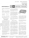
lu service manual
IWOTOROLA
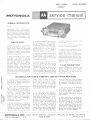
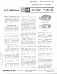
GENERAI INFORMATION
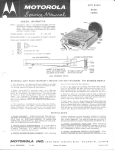
TYPE
Automotive type
all-transistor
superheterodyne AM radio for standard broadcast reception; operates
from 6 voltnegative ground system.
Designed for custom installation in
the I 958- I 963 Volkswagen. This
receiver contains 7 transistors and
2 diodes.
SERVICE NOTES
i. Make certai.nthe rrArr lead is connected to the positive (+) side of the
power source, otherwise, damageto
receiver rnay result. If a battery
eliminator is usedas apower source
in place of a battery, it mustbe well
filtered and regulated.
2, When replacing a power output
transistor, remernber to use the
transistor specified in the parts
list; coat both sides of the transistor insulator with DC-4 grease
(Motorola Part No. I1M490487) and
securely tighten the transistor
mounting s crew;s. When replacing
a1l other transistors, use long-nose
pliers as a heat sink, i. e., grasp
transistor Ieads close to transistor
base withthe pliers to dissipate heat
while soldering.
3. Servicing techniques applicable to
this rnodel can be found in the folMotorola publications:
lowing
rrProfitable Transistor Radio Servicingrr (Motorola Part Number
68P500I IA53) and rrA Discussion of
Radiosil
Car
Transistorized
(Motorola Part No. 68P64980A51).
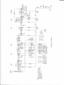
4. POWERTRANSISTOR CURRENT
ADJUSTMENT - AJter rePlaci.ng a
power transistor, the collector current should be checked and adjusted
for proper operation.
A. Insert a 1ow range (0-I or 0-2
arnp) DC amrneter in the PrirnarY
ground return lead of the outPut
transforrner (T-4). Connect the
negative terminal of the rneter to
ground. CAUTION: Be sure the
speaker ground lead is connected in
common with the transforme r ground
lead to the positive terrninal
(see
schematic diagram). Speaker rnust
be connected.
B. Turn the radio on and allow it to
heat up for about I5 minutes.
C. Adjust the bias control (R- I 6) for
a reading of 480 rna with 6.3 volts
input to the radio rrAr' 1ead.
NOTE: Two values of radio input
voltage are given as a convenience to
se rvice personnel in order to ac cornrnodate different power sources. The
current value stated on the schematic
diagrarn is for 7 volts input to the
radio !rAil lead.
TO SET PUSHBUTTONS
Unlock pushbutton by pulling it out
abott i/2', forward of its normal
position. Tune in station and lock
the pushbutton to the station by
pushing it in firrnly.
MOTOROTA AUTO RADIO WAR,R.ANTY SERVICE STATION PROCEDURE
6
6
o\
€
o@
\o
J
J
z.
=
9
(Yt
Fo
rr<
a=
=>
d
1. A Motorola Branded Model is one
that has the Motorola name and is
distributed to dealers through the
Motorola Distributors.
booklet must be fil1ed in bY the
selling dealer at the time of retail
sa1e. The Customerr s Car Radio
Z. This rnodel is guaranteed for all
warranty period to be repaired under
the Motorola Auto Radio Guarantee.
paid by the customer.
4. To obtain your labor a].lowance
for the servicing of the custorners
in-warranty set, fill in the Motorola
Auto Radio .Warranty Labor Claim,
Part Nurnber 54P480884, If you
perform a R & R service,youare
entitled to the R & R allowance, If
you only repair the radio without
R & R service, you are entitled to
the labor allowance. However, if
you perform both R & R and the
repair, then be sure to indicate both
on your clairn form for both allowances. After the form has been
parts and labor, including removal
and re-installation (R & R) for a
period of two years from the date of
purchase. The following rePairs
are not covered under this
guarantee: the elimination of rnotor
noise, tire static, electrical interference and faultY installation.
Charges for these rePairs are to be
3. Before perforrning a warrantY
repair on a Motorola Branded Auto
Radio, you must first receive the
Custornerrs Car Radio Guarantee
and Service Booklet, The installation and rnodel inJorrnation on the
*]OTOROLA ,NC.
PART NO. 68P64988A31
L2-62
Guarantee and Service Booklet rnust
show that the radio is within the
94c^1 rnlEST
RAN D AVEN
mrcE 20 csNTs
G
filled in, rnail the white and green
copies to your Motorola Distributor
for payrnent. The yellow copy is to
be retained in the Service Station
file.
5. The pink copy of the Motorola
Auto Radio Warranty Labor Clairn
is used to return any defective
parts on the repair of the radio to
your Motorola Distributor for free
replacernent.
5. Only those service stations authorized by their Motorola Distributor can perforrn repairs within the
warranty period on a no-charge
basis to the custorner, lf you are
not an Authorized Motorola Auto
Radio Service Station, and you are
interested in handling this service,
please contact your Motorola Distributor for cornplete details.
UE, FRANKLIN PARK, ILLINOIS
PRINTED IN U.5.A.
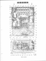
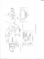
ALIGNMENT
Connect an output rneter across the speaker voice coil. Set volume to rnaximum and tone to treble. Attenuatesignalgeneratoroutputto maintain I watt (1.79 volts across 3,2 ohm load) on output meter at all times.
STEP
GENERATOR
CONNECTION
GEN FREQ
(400 cycle 30% mod)
TUNER SET TO
AD.TUST
REMARKS
262.5
Hi end stop
1,2,3
Adjust for rnaxirnum
1610 Kc
Hi end stop
5, b, /
Adjust for maximum
IF ALI( ]NMENT
I.
To collector of
RF arnp thru
. 1mf & chas sis
&4
RF AL] GNMENT
2.
Ant recept thru
&8
dummy (see
figure )
NOTE:
4, 5 & 5 unless the tuner has b'een tampered with or associated comPoIf necessary, Temove the escutcheon, dial background and the pilot light
socket to expose the core screws. Before proceeding with Step 3, back the tuning cores as far as
possible out of the coils to elirninate their effect on trimmer adjustments.
Do not perforrn Steps
3,
nents have been replaced.
3.
Ant recept thru
16t 0 Kc
Hi end stop
s, 6,7
&8
Tuner carriage
9,10,
& l2
durnmy (see
figure)
1200 Kc
tt
.285'r f rorn Hi
end stop
1610 Kc
6.
Hi end stop
Repeat Steps 4 and 5 until no further increase; Step
screws in place.
5, b,
&8
5
/
Adjust for maximum
r1
Adjust for rnaximum
Adjust for maximurn
should be Iast step. Then, cernent core
ANTENNA
Weak station
7.
around 1400 Kc
Adjust for rnaximum with
radio installed in car and
antenna fully extended.
PLUG TO FIT RECEIVER
ANT-ENNA RECEPTACLE
TO SIGNAL
GENERATOR
TO REOEIVER
}ANTENNA
RECEPTACLE
L__.___l
OAN
ATTACH€D
TO PLUG
DI'UXY ANTETNA DETAIL
NOTES}
ALIGNIIENT IOCATION DETAIL
ffiMffiffiffi
t
tt
.4
4
{
$$
c13
R8
.E&
,Arr
;
S
LEAD
L5
RI
S
PKR
LEAD S
*
%\
VI
25A7?
RF AMP
R2I
R30
c23
c28
c22
c27
C8'{:
I2
TI
Rlt
R20
Rt3
25472
R28
MIXER
V7 SP89I OR
R18
R29
R9.r
R27
R
RIO
R4
Rl6
SP485 PWR AMP
c17
c18
c9 RI7 Ci C5 C24 R22
V3
c2
SM-217
ANT
V5
EPT
MN53
AUDIO
i,SPKR
ilrnos
iJ
g-
R26
r'l
R31
R
E1
c10
25A72
IF AM
E2/
R24
20 R6
R23
R5 R3 Cl4 R2l
PARTS LoCATTON
V6
Ci6
MN53
DRIVER
-
-x
CJ
*2;JHt.at
i=
-Ro-E -<ri*+
q'
5nd
d=
rd
56
sH
-ns
==
-9
Ei
+il
g
|;
F
d
(5
!<
o
C)
E{
s*
-H
I
I
I
C)
a
I
I
-J
j+3
K=
9
a!=<=
n=l
l---l;s idEIE
d- -=E E
=EFEiH
t-qi *; d =
z
^.. -.
:H-== E
l=--I =E --F:;- {
I lg; ;63;li
l=-l =E :====; H
o6;-6
-s3
NE
z*
z
:r
E
?
@---d"l${l
l-t',
=E=t
SzaG
=6->
y=zS s.r
;6HJ
:
;:=
E<9E
€
:
I3li8q
az = <Z=
?ra=rFe
;?*iHES
6-,^iars
l*us;!o
.. E-S65zE
'
4 +E!-CZr
S569tr=l*
z
-
*ffifl
\\\.lll/
=
s
s
w*3
=
5@s
Yl
'
#@=
I
i>
20
d=
d^
?-=9
<Jo
2=2
=r^E
*bE
-*83
=+:
=l
e=
OdO-F
q--=?6
=+.;
-=e=tr:
=r
uE
;=
E
azz*E
z=a z <
Yfi<io
=
:3;=E
==2fr=
a\
=E
z
=
a
k
2
II
o
a
\i
9ts
<e
Hg
I
-V
F6
v3
I -E
a*l
a=g
H
o=
;E
/--$\
<z \
Hov
=EN-0
-
-//
P{
b; ,€t-R=r
\d^R \
E:
;o fN
rg-l
r
//
-F \\
i2 \v
-z
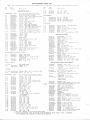
fREPTACEMENT PARTS LIST
NOTE: When ordering parts, specify model number of set j-n addition to part number and description
Ref.
No.
Part
Descr
Number
ipt ion
ELECTRICAL PARTS
of part.
Ref,
No,
Number
Descr
R-29
R-30
R-31
6S125C25
6SL25C2L
65r2sDlo
1O0 LO% j./2W
68 LO70 t/2W
330,00O rO% r/2U
T-4
25C64607A0I OUTpUT (USE 25C64607A02)
Part
ipt ion
NOTE: A11 capacitors are ceramic disc
type unless otherwise specified.
TRANSFORMERS
40 nmf to 430 mmf trimer
2085440L7
.003 mf 200V mylar(USE 8R10110A02)
8R10064434
T-I
24B646L3AQI lST IF: 262.'KC
20 mf to l2O mmf trimmer
20K541014
248646L3AO2 zND IF: 262,5KC
T-2
8.2 nmf 500V f.c.
2lR120r-59
25B646LOAO2 DRTVER (USE 258646rOA03)
2rRt28634
.005 mf 500V
CAPACITORS
c-1
c-2
c-3
c-4
c-5
20 mf to 120 mf trimmer
20K541-014
c-6
.05 mf 2O0V mylar
8KL29455
c-7
.005 nf 200V mylar
8Kl-31769
c-8
2rKr3L254
,05 mf l00V (USE 21A740805)
c-9
.05 nf 100v (USE 21A740805)
c-10 2tKr3t254
150 mmf soov N750 (USE 21R124608)
c-11 2rRL2l228
2IRL2287|
,0o5 mf 500V (USE 2LRL2a634)
c-r2
23K544697
6.4 nf 40V electrolytic (aIso
c-r3
replaces 5 mf used in sone sets)
c-14 23K544697
6"4 mf 40V electrolytic (also
replaces 5 mf used in some sets)
.01 mf 1O0V
c-15 21Kr32103
.002 mf I00V
c-16 2rKL32525
2tD40339453
,03 mf 10OV
c-r7
.01 nf l00V
c-18 21Kr32l-03
SPARK
PLA'IE
c-19 64K530L77
c-20 23K544540
25 nf 3V electrolytic (USE 23C4007rA05 )
C-21 81131799 .0I mf 1O0V mylar
C-22 8Kr31799 .Ol mf lO0V mylar
C-23 8K131799 ,0l nf 100V mylar
C-24 21R410036 1.00 mnf 50OV N75O
C^25 20K54f700 310 nnf to 39O mf trimer
C-26 21K132103 .01 mf IOOV
C-27 23C64722AO2 l-00-500-500 mf/1^6Y electrolytic
C-28 *23K54471A 500 nf 8V electroLytic
C.29 64K53OI77 SPARK PLATE
MISCELLANEOUS ELECTRICAL PARTS
E-l
E-2
DIODE, lN60 (det)
DrODE- rN60 (AGC)
65R1O867
65RI22345
BULB,
FUSE,
5OC5a"3225
E-3
E-4
E-5
COILS
48K644681
48K644681
&
5"; 3.2O VC (USE
pilot lie;ht: #44 (6.3V)
5 amp: 1 ag
SPEAKER, PM:
50c5627Qi7)
CHOKES
L-T,2.3 ,4
25B5+3338
L-5
248647A5403
L-6
CHOKE, R!'
R-8 &12 18C647344O3 VOLIJIIE, TONE & SI{: volloK,tone I00K
R-16
18c64735A08 BIAS: 3oo 20% 2\l
R-4
R-5
R-6
R-7
R-8
R-9
R-10
R-11
B-12
R-r3
R-14
R-I5
R-16
R-17
R-18
R-19
R-20
B-21R-22
R-23
R-24
R-25
&-26
R-27
R-28
2SA72 (RF amp - USE 48K134601)
2SA72 (mixer)
4aKr34602
48K134601
48Rr34635
48Kr34600
484124318
SM2l7 (oscillator)
2SA72 (IF anp - USE 48K134601)
(audio anp)
MN53
4aRr3464r
Ii,lN53 ( dr
iver
)
SP891 (pwr - also replaces SP485)
48R134646
MECHANICAL PARTS
*7K5447L2
428733793
#I5K5447L5
#15K543815
13C543880
14A5438f0
36K544747
36K344748
36K544760
BACKGROUND, dial scale
CLIP, IF mtg
COVER, back (rreat sink)
COVER, bottom
ESCUTCHEoN, dial
INSULATOR, power translstor
KNOB, dummy
KNOB, tone
KNOB, vol & tuning
ntg
29A64647AOL LUG. termj-na1 ("tr!' lead)
I3K544668 MASK, dial scale
PALNUT: 3/8-32x9/L6 (vol control mtg)
257051
RECEPTACLE. antenna
94472L48
9K544713
RECEPTACLE, fuse
*34864793402 SCALE, dial
SCREW, tappine', i6xI/2 (pwr tran3K560695
sistor ntg)
SOCKET, pilot light
9A543879
(pw;' amp)
SOCKET, transistor
98542339
SPEED NUT (dial scal,e ret)
2s7o87
29A762aO
TERUINAL, pln: black (spkr leads)
29K762a2
TERMINAL, pin: white (spkr leads)
74543889
a8538244
BnACKET
, radi.o mtg
noise suppression (gen-
CAPACITOR,
erator
)
noise suppression (igni-tion coil)
#LV544O36 KIT, radio installation
29A64647A01 LUG, termj,nal (ignition
coil
capac itor )
25r376
NUT. hex: 3/8-32xL/2x3/32 {r^d,ao
front ntg)
6L4l4L
SUpmESSOR, distributor
1V6496tA22 TRIMPLATEI j-ncls tubins
88544383
CAPACITOR,
Al1 resistors are insulated composition
type unless other specified.
22,OOO LO% L/zY
6S125C81
65 l25Do2
150 , 0o0 rOf3 V2fr
6sr25c85 33,ooo
ro% r/zur
TUNER PARTS
6s125C95
82.ooo lo% L/2tt {in some sets)
(
sets)
some
43K47L633
BEARING.
in
ball
l/2Y
6S125C97
OOO
r0%
lOO ,
1V564641
CLUTCH & DISC ASSEU| incl set screw
56,000 l.oio I/2Y
6Sr25C91
L-1,2, *1V418O0A32 COILS & ltIG PLATE ASSEM: incl L-1.
47OO 1O% l/2W
6S125C64
22O LO% l/21{
3,&4
L-2,L-3,L-4" I' mtg plate
6S125C33
SEE CONTROLS
76K563288 CORE" iron (oscillator)
68,000 LO% Lizttt
6S125C93
76K5632A8 CORE, i.ron (RF and ant)
1O0O LOI. r/2W
18563899
GEAn BUSHING & DISC ASSEM:
6Sr25C49
27,OOO lO% L/2V
6Sr25C83
58562438
GROIIIdET, core mtg
SEB CONTROLS
#45A4L254AOL LINK connecting
680,000 rO% L/2v
6S125Dr8
1B4O875AO2 POINTER
10 LO% l/2v
6Sr25C0l
'i38K56521O PUSTIBUTI9N
NTC
fixed
carbon
n%
L/2I:
6K5438O0
l0
49A5624aO ROLLER. clutch release
(UsE 6K540634)
sCREw li NUT ASSEMBLY: adiustabl-e
M62830
SEE
CONTROLS
3A563128
SCREF, set:- 4-4Ox5/L6 (ctutch &
6s125C25
100 LO% l/2fr
disc assem)
47OO LO% L/2Y
6sr25C64
SCBEW. tappine: 4-4oxl/4 (coits ntg)
35127896
47OO lO% L/zU
6S125C64
44B56375A SHAFT. manual tuning
l5O0 lofo l/2V
4LA562449 S4ING" anti rattle (clutch release
6Sf25C53
22Oo ro% L/zv
6Sr25C57
bar)
27oo lO% L/zU
6SI25C59
4LA562447 SmINc, ctutch l'elease
47O IO% l/zt
6SI25C4I
4LA4L255AO1 SPRING, connecting l-i,nk
6S1,25C81 22,OOO lo% L/zt
418562503 SmINc, pointer tension
*77K5652O9
6Sr25C75
12,000 IO% L/zfi
TUNS1, AT430: complete
6S125C25
100 lO% L/2U.(in some sets)
4X501364
WASUER, "C', (manual shaft ret)
6s125C23
4K692I88
82 Lo% l/2v {in sone sets)
ilASHER, ,'C" (pointer ret)
6SI25C25
4A56243L
ilASI{ER, cup (clutch release spring)
IO0 LO% L/2Y
4K564253
WASIER, spring (nanual shaft)
6S125C64
47OO LO% L/2r
* NEI{ ITEM. APMARS IN ANY LIST F-OR FIRST TITE
f LIMITED REPLACEUENT llElt" I'IIE VOLUIIiE OF RESLACEI'ENT ON TSESE IIEMS IS SMALL, TEEREFORE,
IT IS SUGCESTED TITAT ORDERING BE DONE ONLY AS REQUIRED.
RESISTORS
R-3
v-l
v-2
v-3
v-4
v-5
v-6
v-7
INSTALLATION PARTS & ACCESSORIES
SEE TIJNER PARTS
CHOKE. filter
CONTROLS
R-l
R-2
TA,ANSISTORS
- NOTE:

![[U4.01.05] Nouveautés et modifications de la version 9](http://vs1.manualzilla.com/store/data/006369985_2-e1f8c5343dcc24307fb4edf9c2afe34f-150x150.png)


![[U4.01.05] Nouveautés et modifications de la version 9](http://vs1.manualzilla.com/store/data/006377078_1-fb5eeebef33750ea818bdf7ce8f91452-150x150.png)