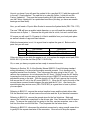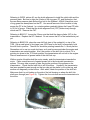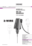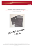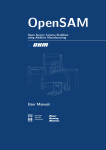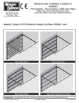
1
911 Clutch Job
So you have one of the best 911s there is, a ’87-’89 G50 Porsche. However, after many
years of service, it is time for a clutch. Maybe, the rubber clutch disc has failed, or the
clutch is getting hard to disengage, or the shifting fork has broken, or the needle bearing
associated with the shaft for shift fork have failed. Anyway, it is time to drop the engine
and transmission. The Pelican Parts site has a great technical article on how to drop a
911 motor;
http://www.pelicanparts.com/techarticles/911_engine_drop/911_engine_drop-1.htm.
The first step is to have, beg, borrow, or buy a copy of the Bentley Service Manual. This
technical article will reference the manual. Of course, before starting the project, be
sure to read the Bentley Manual Section 101. Also, buy and read Wayne’s book, 101
Projects for Your 911. Wayne does an excellent job describing the procedure for clutch
replacement on 911s. Naturally, Pelican Parts is a great place to find the above
publications. There is also a technical article on how to replace a clutch
(http://www.pelicanparts.com/techarticles/911_clutch_replace/911_clutch_replace1.htm)
When reading the above technical articles and books, keep in mind that they are not
focused towards a late 3.2 Carrera’s clutch. Subsequently, a G50 clutch tech article
needed to be written.
Before you start, a parts listing is needed. Pelican parts sells the ‘G50 Transmission
Option 1 kit containing the items you will need. Below is a list of the stuff you will need.
Item
1
2
3
4
5
6
7
8
Qty
1
1
1
9
1
1
1
1
Part Number
PET-TOL-CA3
OC-54
C-606-230-00
H-101-206-00
L-116-080-08
L-116-813-06
H-116-014-02
9
2
90011901702
10
11
12
13
14
15
16
1
9
9
1
1
1
1
L-116-023-03
J-067-045-02
N-012-241-8
Q-102-111-00
K-113-426-41
Q-102-111-00
000 043 024 00
Description
Clutch Alignment Tool
Oil Filter
Oil Pressure Switch
Flywheel Bolts
Throw Out Bearing
Updated TOB Guide Tube
Spring Clutch Disc
Bronze Bushing G50 Shift
Fork Shaft Update Kit
TOB Guide Tube Bolts
6mmx15mm cheese head
Pressure Plate
Pressure Plate Blots
Pressure Plate Washers
Flywheel Pilot Bearing
Flywheel Seal
Pilot Bearing
(Porsche) Olista ® Long
time GreaseSpecial
Grease
If your 911 was built after April 6 1989 or the shift fork update has been done, then order
the ‘G50 Transmission Option 2 Kit’ which does not contain item 8. If you wish to
replace the shift fork shaft and the needle bearings for a post April 6 1989 911, then
order the 911 G50 Update Kit (915-G50-KIT) also (see Figure 1).
Figure 1 – Factory G50 update and old Shift Fork Shaft
What is the difference between the factory update kit (915-G50-KIT) and the Bronze
bushing G50 kit? Referring to Bentley Manual, section 301-20, a special long drill bit
tool (000 721 929 20) is required for the factory update. The Bronze bushing does not
require any special tools or drilling (see Figure 2). Also, the bronze bushing kit does not
have needle bearings that are known to still fail.
Figure 2 – New Shaft and New Fork
How do you know if you will need the update kit for a pre-April 6 911 with the engine still
in the car? Good question! The safe bet is to order the Option 1 clutch kit and the
Factory Update kit. Then use the bronze bushing kit if the update has been done or
use the Factory Update kit if an update has been done (this way you have new needle
bearings and new shaft).
Also, you will need a 12 point Allen Socket to remove the flywheel bolts (PEL-TOL-1170)
The new TOB will have a smaller inside diameter, so you will need the updated guide
tube as seen in Option 1. Remove the old guide tube is a trick, but more on this later.
Of course you will need 10-12 quarts of oil that is available from your local parts place
as well as a bunch of rags and hand cleaner.
While the transmission is out, it is a good time to replace the gear oil. Below are the
parts that you will need.
Qty
1
2
Part Number
SWP-201
J-123-011-20
Description
Swepco 201
Drain Plug Seal 22x27
Other nice things to do while the engine is out, is to replace the engine sound pad (PP#
M-556-281-01) and the fuel filter (PP# F-110-253-04).
Ok, so now you have your parts and are ready to remove the motor.
Referring to Section 101-2 of the Bentley Manual (BM101-2) and following standard
safety procedures, it is time start the engine removal process. First, disconnect the
negative terminal from the batter. Then, disconnect the wire going to the AC unit. To
remove the compressor, do not disconnect the AC lines! Simply loosen the AC belt by
loosening the four blots as seen in the bottom picture of BM101-2 and then loosen the
adjustment screw on the side. With the tension off the AC belt, remove the four bolts
that secure the AC unit to the AC mount (BM101-2) Move the AC unit to the side of the
car and place a several towels between the paint and the AC Unit. Also having the
special engine bay service cover (PEL-COLSC002) is a great item to have to protect
your cars paint.
Referring to BM101-3, remove the various breather hoses and the plastic elbow tube.
Pull the electrical cover off and remove the coil wire and the 14 pin electrical connector.
Referring to BM101-4, remove the ground wires for the fuel injections. Mark and
remove the 3 electrical connections on the drivers side. Also, disconnect the O2 sensor
wires. To remove the supply fuel line going to the filter, use two wrenches, one on the
fuel line, the other one the fuel filter. Then, separate the fuel return lines.
Referring to BM101-5, disconnect the electrical connectors by using a small screw drive
to gently lift the square steel wire off the connector. Be sure not to drop the square
wire. After a connector is pulled loose, put the square wire back onto the connector. To
remove the cruise control (CC), follow the BM. However, later 911s have a different CC.
Simply remove the three 6mm nuts that hold the unit to engine bay and disconnects its
associated wiring harness (see Figure 3). Wash your hands and then disconnect the
speedometer wires by gently pulling the wires away form the connector. Have a buddy
underneath the car gently pull the wires and the rubber grommet through the bulkhead.
Figure 3 – 3 nuts for the cruise control
Referring to BM101-6, remove the hex bolt and separate the shafts. Note the AC lines
may be in the way, if so remove the clamps and push the AC line out of the way.
Referencing the second picture, disconnect accelerator pull rod ball joint. Note: there is
a special metal pin that must be removed first. Clean the ball joint and you will see the
metal retain wire. On top of the joint, you can feel the end of the wire, pull that off the
joint and then pull the wire. Only when the wire is out will you be able to remove the ball
joint. Also, now is a good time to use two 10mm wrenches to separate the engine
accelerator wire from the bracket. This will help keep the CVs out of the way. In the
third picture, don’t do what they recommend. Instead use a 19mm and a 14mm wrench
to separate the flexible hydraulic line from the hard line. Be sure to catch the brake fluid
on a suitable container.
Referring to BM101-7, Ignore the first 2 pictures. Also, ignore the third picture. Since
the clutch hydraulic lines are separated, no need to remove the clutch master cylinder.
Referring to BM101-8, drain the oil. Be sure to have a large oil catch. Then, remove the
sway bar and then disconnect the starter wire. Now for the fun part, remove the CVs.
Have a buddy operate the parking break while you loosen the CV bolts. Do not forget
to loosen the ground strap. Assuming you don’t have a shop lift, loosen the two
transmission bolts a couple of turns. Do not take them out yet! Loosen the 2 engine
support cross-member bolts a couple of turns. Note, there is a chance the cross
member will break or crack when removing the bolts. To help minimize this, place a
small piece of 2x4 wood between the drivers side bolt and the back of the car. Now to
remove the motor, I have used a good floor jack and various pieces of wood. I also
place wood blocks under the heat exchangers as a safety catch. Anyway, there is a
bunch of different ways to drop the motor. Read and ask questions, and then decided
what works best for you. With the motor and transmission properly supported, remove
the 2 transmission bolts and the 2 engine bolts. Now slowly lower the motor and then
raise the rear of the car. Roll the drive train back and you are ready to separate the
transmission from the motor.
Referring to BM101-15, separate the transmission from the engine. First, detach the
reverse light and the starter wires. Then remove the clutch cross shaft. Though the
manual states 6mm, on some G50s, it is 8mm. If you don’t have a slide hammer, a long
bolt and a pair of pliers will work. While supporting the transmission, remove the 4 nuts
that secure the bell housing to the engine.
Ok now for the fun stuff.
Referring to BM102-4, remove the 9 bolts that secure the pressure plate to the flywheel.
The pressure plate may require a little convincing that it wants to separate from the
flywheel. With the pressure plate and disc now removed, time to remove the flywheel.
Use the special 12 point allen socket and an impact wrench to loosen the 9 flywheel
bolts. After removing the 9 blots, simply wiggle the flywheel to separate it from the
engine. Next, gently tap out the pilot bearing from the flywheel with a big socket. The
last picture on page BM102-4 shows the oil pressure switch. Replace the switch.
Since the motor is out of the car, it is a good idea to clean up the motor. Of course, no
better time to adjust the valves. Also, inspect the engine sensors to see if the 2 wire
upgrade has been done.
Referring to BM301-23, inspect the flywheel. Replace if it looks bad it must be replaced.
According to the Bentley manual, the pilot bearing is not pressed into the flywheel.
However, on the ’89 911, the pilot bearing was pressed into the flywheel. The new pilot
bearing was frozen and then pressed into the flywheel by using the old pilot bearing as a
guide to tap the new bearing in to position.
Referring to Wayne’s book page 34 (WD34), replace the engine rear main seal. Clean
the old seal and use it as a guide to tap in the new seal. It is a good idea to pre-lube the
new seal with oil. Another recommendation is to use a little Loctite gasket sealer 518 on
the outside of the seal.
After installing the new rear main seal and the pilot bearing, installing the flywheel is
next. It requires 9 new flywheel nuts with a small amount of blue Loctite on the treads.
In a circular pattern, gradually lighten the 9 blots until 90 NM of torque is reached.
Referring to BM301-24 & 25, install the Through Out Bearing (TOB) (see Figure 4) on to
the new pressure plate (PP). Using the old PP and old TOB as a guide (see Figure 5)
and carefully studying the picture on page BM301-25, install the new TOB onto the new
PP. If you don’t have a press, have a big friend (180 Lbs + ) stand on the pressure plate
while you slip the locking ring into place. It is a bit tricky, but it can be done this way. Be
sure that the locking ring snaps into place!
Figure 4 - New Throw Out Bearing and Pressure Plate
Figure 5 - Old Pressure Plate and Throw Out Bearing
NEXT: Remove the old ring gear from the old PP and install in onto the new PP. If you
forget this step, you will have to take the motor out again. DO NOT FORGET TO
INSTALL THE RING GEAR!!!. See Figure 6 that shows a big OOPS about to happen
(no ring gear on the PP).
Figure 6 - New Clutch Disc and Pressure Plate in position
Check that the new guide tube (GT) fits
nicely into the new TOB. The original GT
has a larger OD than the new GT. If you
have the new style GT and TOB, skip the
next step.
If the original guide tube is attached to the
transmission, and a new style TOB is use,
the guide tube (GT) will need to be
replaced. Two Phillips head 6mm bolts
secure the GT to the transmission bell
housing. They don’t want to come loose!
Carefully, drill out the head of the two
Phillips screws. Remove the old GT.
Next, use a small reverse drill bit and a
drill motor to drill out the remaining treads.
The reverse drill bit should immediately
begin to back out the remaining treads
(see Figure 7) Install the new GT with
two new screws (Cheese Head Phillips
6x15mm 90011901702)
Figure 7 - Drilled out bolts and bit
Referring to WD35, picture #5, use the clutch alignment to install the clutch disk and the
pressure plate. Be sure to align the 9 holes of the ring gear, PP, and flywheel so that
the new 8mm pressure plate bolts will go bolt to the flywheel. AGAIN, check that a set
of ring gears has been placed on the PP. Use a small amount of blue Locktite to help
secure the PP to the flywheel. In a circular pattern gradually tighten the 9 new PP bolts
to 18 Lbf of torque. Check that the clutch alignment tool (CAT) slides nicely through
clutch and PP. Remove the CAT.
Referring to BM101-7, loosen the 2 8mm nuts that hold the slave cylinder (SC) to the
transmission. Replace the SC if desired. Do not secure the SC to the transmission just
yet.
Referring to BM301-24, place the new shift fork (part of the update kit) on top of the
TOB. Use a small piece of duct tape (now 1002 uses for the stuff) to temporarily hold
the shift fork in position. The shift for should be pointing towards the 1 o’clock position.
Remember not to use too much duct tape, as it must be removed when the engine and
transmission are mated together. Also, the position of the shift fork is critical, if it is
pointing too close to the 12 O’clock position, the transmission will not bolt to the engine.
Place a small amount of grease inside of the shift fork cup.
While a couple of buddies hold the motor steady, push the transmission towards the
motor. Place a small amount of special grease on to the horizontal transmission
splines. This may take a couple of tries varying the position of the splines on the
transmission. Check that the shift fork is still in position. Hopefully, the transmission
has been pushed forward enough so that you can get the starter’s nut on the top, and
another nut diagonally on the bottom. After which, check the position of the shift fork.
Make sure that it is not binding on the side of the bell housing or where the shift fork
shaft goes through (see Figure 8). Tighten the four nuts that secure the transmission to
the motor.
Figure 8 - New Shift Fork in Position
After the transmission has been bolted to the engine, carefully remove the duct tape that
secures the shift fork shaft.
Referring to BM301-24 install the shift fork shaft. Note: the aftermarket-retaining
bracket connected to the new shift fork shaft may be too long, bend as needed. To
install the new shift fork shaft, carefully lift the shift until it aligns with the holes. Then
slide the shift fork shaft into position. After installing the shaft, install the retaining bolt
(See Figure 9).
Figure 9 - New Slave Cylinder and Shift Fork Shaft
Referring to BM301-11 and BM301-12, install the clutch slave cylinder (See Figure 9).
Apply a small amount of grease on plunger’s tip. Though not installed by the factory,
also use 2 8mm lock washers or spring washers when securing the SC to the
transmission. Be sure that the tip of the SC slides into the receiving part of the shift fork.
Referring to BM101-15, install the reverse lights and the starter wires. Note, the main
starter wire only needs to be place onto the starter; the 8mm nut will secure the wire to
the starter after the engine is installed. Use a large new tie wrap to secure the wires to
the starter.
Ok, now check everything, 4 transmission / engine nuts tight? Is the slave cylinder
fastened and the hydraulic line secured? Also, now is the best time to loosen the
bleeder valve for the SC. Are the speedometer wires secured? Again, ask yourself,
are there two ring gears, 1 for the sensor, the other for the starter.
Referring to BM101-10, install the motor and transmission into the car. Check to make
sure that the CVs, wires, hoses, and shift coupling is clear while the motor and
transmission mates to the car. It is easier to install the 2 transmission bolts first, but only
turn them a few revolutions. With the transmission in place, and the motor not bolted in,
now is a good time to connect all those hoses and wires (See Figure 10). Next install
the 2 engine support bolts.
Figure 10 - Raising the Motor
Referring to BM101-11, torque the two transmission support bolts, then install the CV
Joints, transmission shift coupling, starter wire, ground wire, accelerator shaft,
speedometer wires, oil lines (also, make sure the oil drain plugs are tight!!), and secure
the compressor for the AC and the AC lines underneath.
Next step is to work on the hydraulic system for the clutch. First, do not secure the
Slave Cylinder’s hydraulic line. Instead, top off the brake fluid reservoir, (ATE Blue is
recommended). Place a suitable container underneath the car to catch brake fluid.
While wearing safety glasses, have a friend hold the clutch petal up, get ready to catch
the fluid as he presses down on the clutch pedal. While he holds the pedal down, place
your thumb over the end of the hydraulic line. Then have your friend pull back on the
clutch pedal (CP). With the CP in the full up position, remove your thumb from the
hydraulic line. Next, have your friend press down on the CP. Repeat the process until a
nice flow of fluid comes out of the hydraulic line. Then, immediately thread the 2
hydraulic together. Tighten the lines. This process speeds up the MC bleeding
procedure.
Referring to BM301-10, now for bleeding the Slave Cylinder (SC). Since the line was
pre-bled in the previous step, the SC should start to work after a couple of bleeds.
Double check that the gas lines are tight, the vacuum line for the brake booster is tight,
the oil lines and oil drain plugs are tight. Then connect the battery cables.
Now it is time to install about 9 quarts of oil. After which, remove the fuel pump relay
and then turn the starter over for 20 seconds. Wait 30 seconds and repeat the process
until the oil pressure light goes out. Then install the fuel pump relay.
Again double-check everything and then try to start the car. It should start, if not, maybe
the alarm system needs to be reset. While sitting in the car, lock and unlock the doors a
couple of times. The car should start. If it does, then it is time for the proverbial test
drive.
After a successful test drive, it is time to congratulate yourself. Now it is Beer Time…