1
External I/O Expansion Unit
Installation and Service Manual
Manual Code C120-E329-03EN
Part No. 820-0282-10
June 2007, Revision A
Copyright 2007 Sun Microsystems, Inc., 4150 Network Circle, Santa Clara, California 95054, U.S.A. All rights reserved.
FUJITSU LIMITED provided technical input and review on portions of this material.
Sun Microsystems, Inc. and Fujitsu Limited each own or control intellectual property rights relating to products and technology described in
this document, and such products, technology and this document are protected by copyright laws, patents and other intellectual property laws
and international treaties. The intellectual property rights of Sun Microsystems, Inc. and Fujitsu Limited in such products, technology and this
document include, without limitation, one or more of the United States patents listed at http://www.sun.com/patents and one or more
additional patents or patent applications in the United States or other countries.
This document and the product and technology to which it pertains are distributed under licenses restricting their use, copying, distribution,
and decompilation. No part of such product or technology, or of this document, may be reproduced in any form by any means without prior
written authorization of Fujitsu Limited and Sun Microsystems, Inc., and their applicable licensors, if any. The furnishing of this document to
you does not give you any rights or licenses, express or implied, with respect to the product or technology to which it pertains, and this
document does not contain or represent any commitment of any kind on the part of Fujitsu Limited or Sun Microsystems, Inc., or any affiliate of
either of them.
This document and the product and technology described in this document may incorporate third-party intellectual property copyrighted by
and/or licensed from suppliers to Fujitsu Limited and/or Sun Microsystems, Inc., including software and font technology.
Per the terms of the GPL or LGPL, a copy of the source code governed by the GPL or LGPL, as applicable, is available upon request by the End
User. Please contact Fujitsu Limited or Sun Microsystems, Inc.
This distribution may include materials developed by third parties.
Parts of the product may be derived from Berkeley BSD systems, licensed from the University of California. UNIX is a registered trademark
in the U.S. and in other countries, exclusively licensed through X/Open Company, Ltd.
Sun, Sun Microsystems, the Sun logo, Java, Netra, Solaris, Sun Ray, Answerbook2, docs.sun.com, OpenBoot, and Sun Fire are trademarks or
registered trademarks of Sun Microsystems, Inc. in the U.S. and other countries.
Fujitsu and the Fujitsu logo are registered trademarks of Fujitsu Limited.
All SPARC trademarks are used under license and are registered trademarks of SPARC International, Inc. in the U.S. and other countries.
Products bearing SPARC trademarks are based upon architecture developed by Sun Microsystems, Inc.
SPARC64 is a trademark of SPARC International, Inc., used under license by Fujitsu Microelectronics, Inc. and Fujitsu Limited.
The OPEN LOOK and Sun™ Graphical User Interface was developed by Sun Microsystems, Inc. for its users and licensees. Sun acknowledges
the pioneering efforts of Xerox in researching and developing the concept of visual or graphical user interfaces for the computer industry. Sun
holds a non-exclusive license from Xerox to the Xerox Graphical User Interface, which license also covers Sun’s licensees who implement OPEN
LOOK GUIs and otherwise comply with Sun’s written license agreements.
United States Government Rights - Commercial use. U.S. Government users are subject to the standard government user license agreements of
Sun Microsystems, Inc. and Fujitsu Limited and the applicable provisions of the FAR and its supplements.
Disclaimer: The only warranties granted by Fujitsu Limited, Sun Microsystems, Inc. or any affiliate of either of them in connection with this
document or any product or technology described herein are those expressly set forth in the license agreement pursuant to which the product
or technology is provided. EXCEPT AS EXPRESSLY SET FORTH IN SUCH AGREEMENT, FUJITSU LIMITED, SUN MICROSYSTEMS, INC.
AND THEIR AFFILIATES MAKE NO REPRESENTATIONS OR WARRANTIES OF ANY KIND (EXPRESS OR IMPLIED) REGARDING SUCH
PRODUCT OR TECHNOLOGY OR THIS DOCUMENT, WHICH ARE ALL PROVIDED AS IS, AND ALL EXPRESS OR IMPLIED
CONDITIONS, REPRESENTATIONS AND WARRANTIES, INCLUDING WITHOUT LIMITATION ANY IMPLIED WARRANTY OF
MERCHANTABILITY, FITNESS FOR A PARTICULAR PURPOSE OR NON-INFRINGEMENT, ARE DISCLAIMED, EXCEPT TO THE
EXTENT THAT SUCH DISCLAIMERS ARE HELD TO BE LEGALLY INVALID. Unless otherwise expressly set forth in such agreement, to the
extent allowed by applicable law, in no event shall Fujitsu Limited, Sun Microsystems, Inc. or any of their affiliates have any liability to any
third party under any legal theory for any loss of revenues or profits, loss of use or data, or business interruptions, or for any indirect, special,
incidental or consequential damages, even if advised of the possibility of such damages.
DOCUMENTATION IS PROVIDED “AS IS” AND ALL EXPRESS OR IMPLIED CONDITIONS, REPRESENTATIONS AND WARRANTIES,
INCLUDING ANY IMPLIED WARRANTY OF MERCHANTABILITY, FITNESS FOR A PARTICULAR PURPOSE OR NONINFRINGEMENT, ARE DISCLAIMED, EXCEPT TO THE EXTENT THAT SUCH DISCLAIMERS ARE HELD TO BE LEGALLY INVALID.
Please
Recycle
Copyright 2007 Sun Microsystems, Inc., 4150 Network Circle, Santa Clara, California 95054, Etats-Unis. Tous droits réservés.
Entrée et revue tecnical fournies par FUJITSU LIMITED sur des parties de ce matériel.
Sun Microsystems, Inc. et Fujitsu Limited détiennent et contrôlent toutes deux des droits de propriété intellectuelle relatifs aux produits et
technologies décrits dans ce document. De même, ces produits, technologies et ce document sont protégés par des lois sur le copyright, des
brevets, d’autres lois sur la propriété intellectuelle et des traités internationaux. Les droits de propriété intellectuelle de Sun Microsystems, Inc.
et Fujitsu Limited concernant ces produits, ces technologies et ce document comprennent, sans que cette liste soit exhaustive, un ou plusieurs
des brevets déposés aux États-Unis et indiqués à l’adresse http://www.sun.com/patents de même qu’un ou plusieurs brevets ou applications
brevetées supplémentaires aux États-Unis et dans d’autres pays.
Ce document, le produit et les technologies afférents sont exclusivement distribués avec des licences qui en restreignent l’utilisation, la copie,
la distribution et la décompilation. Aucune partie de ce produit, de ces technologies ou de ce document ne peut être reproduite sous quelque
forme que ce soit, par quelque moyen que ce soit, sans l’autorisation écrite préalable de Fujitsu Limited et de Sun Microsystems, Inc., et de leurs
éventuels bailleurs de licence. Ce document, bien qu’il vous ait été fourni, ne vous confère aucun droit et aucune licence, expresses ou tacites,
concernant le produit ou la technologie auxquels il se rapporte. Par ailleurs, il ne contient ni ne représente aucun engagement, de quelque type
que ce soit, de la part de Fujitsu Limited ou de Sun Microsystems, Inc., ou des sociétés affiliées.
Ce document, et le produit et les technologies qu’il décrit, peuvent inclure des droits de propriété intellectuelle de parties tierces protégés par
copyright et/ou cédés sous licence par des fournisseurs à Fujitsu Limited et/ou Sun Microsystems, Inc., y compris des logiciels et des
technologies relatives aux polices de caractères.
Par limites du GPL ou du LGPL, une copie du code source régi par le GPL ou LGPL, comme applicable, est sur demande vers la fin utilsateur
disponible; veuillez contacter Fujitsu Limted ou Sun Microsystems, Inc.
Cette distribution peut comprendre des composants développés par des tierces parties.
Des parties de ce produit pourront être dérivées des systèmes Berkeley BSD licenciés par l’Université de Californie. UNIX est une marque
déposée aux Etats-Unis et dans d’autres pays et licenciée exclusivement par X/Open Company, Ltd.
Sun, Sun Microsystems, le logo Sun, Java, Netra, Solaris, Sun Ray, Answerbook2, docs.sun.com, OpenBoot, et Sun Fire sont des marques de
fabrique ou des marques déposées de Sun Microsystems, Inc. aux Etats-Unis et dans d’autres pays.
Fujitsu et le logo Fujitsu sont des marques déposées de Fujitsu Limited.
Toutes les marques SPARC sont utilisées sous licence et sont des marques de fabrique ou des marques déposées de SPARC International, Inc.
aux Etats-Unis et dans d’autres pays. Les produits portant les marques SPARC sont basés sur une architecture développée par Sun
Microsystems, Inc.
SPARC64 est une marques déposée de SPARC International, Inc., utilisée sous le permis par Fujitsu Microelectronics, Inc. et Fujitsu Limited.
L’interface d’utilisation graphique OPEN LOOK et Sun™ a été développée par Sun Microsystems, Inc. pour ses utilisateurs et licenciés. Sun
reconnaît les efforts de pionniers de Xerox pour la recherche et le développement du concept des interfaces d’utilisation visuelle ou graphique
pour l’industrie de l’informatique. Sun détient une license non exclusive de Xerox sur l’interface d’utilisation graphique Xerox, cette licence
couvrant également les licenciés de Sun qui mettent en place l’interface d’utilisation graphique OPEN LOOK et qui, en outre, se conforment
aux licences écrites de Sun.
Droits du gouvernement américain - logiciel commercial. Les utilisateurs du gouvernement américain sont soumis aux contrats de licence
standard de Sun Microsystems, Inc. et de Fujitsu Limited ainsi qu’aux clauses applicables stipulées dans le FAR et ses suppléments.
Avis de non-responsabilité: les seules garanties octroyées par Fujitsu Limited, Sun Microsystems, Inc. ou toute société affiliée de l’une ou l’autre
entité en rapport avec ce document ou tout produit ou toute technologie décrit(e) dans les présentes correspondent aux garanties expressément
stipulées dans le contrat de licence régissant le produit ou la technologie fourni(e). SAUF MENTION CONTRAIRE EXPRESSÉMENT
STIPULÉE DANS CE CONTRAT, FUJITSU LIMITED, SUN MICROSYSTEMS, INC. ET LES SOCIÉTÉS AFFILIÉES REJETTENT TOUTE
REPRÉSENTATION OU TOUTE GARANTIE, QUELLE QU’EN SOIT LA NATURE (EXPRESSE OU IMPLICITE) CONCERNANT CE
PRODUIT, CETTE TECHNOLOGIE OU CE DOCUMENT, LESQUELS SONT FOURNIS EN L’ÉTAT. EN OUTRE, TOUTES LES
CONDITIONS, REPRÉSENTATIONS ET GARANTIES EXPRESSES OU TACITES, Y COMPRIS NOTAMMENT TOUTE GARANTIE
IMPLICITE RELATIVE À LA QUALITÉ MARCHANDE, À L’APTITUDE À UNE UTILISATION PARTICULIÈRE OU À L’ABSENCE DE
CONTREFAÇON, SONT EXCLUES, DANS LA MESURE AUTORISÉE PAR LA LOI APPLICABLE. Sauf mention contraire expressément
stipulée dans ce contrat, dans la mesure autorisée par la loi applicable, en aucun cas Fujitsu Limited, Sun Microsystems, Inc. ou l’une de leurs
filiales ne sauraient être tenues responsables envers une quelconque partie tierce, sous quelque théorie juridique que ce soit, de tout manque
à gagner ou de perte de profit, de problèmes d’utilisation ou de perte de données, ou d’interruptions d’activités, ou de tout dommage indirect,
spécial, secondaire ou consécutif, même si ces entités ont été préalablement informées d’une telle éventualité.
LA DOCUMENTATION EST FOURNIE “EN L’ETAT” ET TOUTES AUTRES CONDITIONS, DECLARATIONS ET GARANTIES EXPRESSES
OU TACITES SONT FORMELLEMENT EXCLUES, DANS LA MESURE AUTORISEE PAR LA LOI APPLICABLE, Y COMPRIS
NOTAMMENT TOUTE GARANTIE IMPLICITE RELATIVE A LA QUALITE MARCHANDE, A L’APTITUDE A UNE UTILISATION
PARTICULIERE OU A L’ABSENCE DE CONTREFACON.
Contents
Preface
1.
xv
Overview
1.1
1–1
General Description
1.1.1
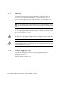
Chassis
1.1.2
Power Supply Units
1.1.3
AC Power
1.1.2.2
Fans
I/O Boats
Card Slots
1.2.1
1.3
1–4
1.1.2.1
1.1.3.1
1.2
1–2
1–5
1–6
1–6
Types of I/O Boat
1–8
1–9
Carriers
1–10
1.2.1.1
Carrier Slots
1.2.1.2
Dummy Cards
1.2.2
Link Kits
1.2.3
Cable Management
1–10
1–11
1–12
1–14
1.2.3.1
Minimum Bend Radius for Link Cables
1.2.3.2
Cable Management Unit
Carriers
1.3.1
1–4
1–15
1–16
1–17
Carrier Removal and Insertion
1–18
v
1.3.2
1.3.3
1.3.4
1.4
2.
1–20
1.3.2.1
PCI Card Shapes Determine Card Lock Locations
1.3.2.2
Using Card Locks with Short PCI Cards
1.3.2.3
Using Card Locks with Unusual Card Shapes
PCI Card Mounting Problems
1.3.3.1
Tilted Cards
1.3.3.2
Hidden Problems
Carrier Keys
1–25
1–25
1–26
1–30
1.4.1
Single Boat Configuration
1.4.2
Dual Boat Configuration
1.5
LEDs
1–33
1.6
System Management
1.7
Site Preparation
1–31
1–31
1–32
1–35
1–35
1.7.1
Physical Requirements
1.7.2
Electrical Requirements
1–36
1–36
1.8
Service Information
1.9
Electrostatic Discharge Precautions
1–37
1–39
Installing the External I/O Expansion Unit in a Cabinet
2–1
2.1
Tools
2–1
2.2
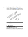
Installing the Rails in a Type S Rack
2.3
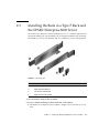
Installing the Rails in a Type F Rack and the SPARC Enterprise 8000
Server 2–7
2.4
Installing the External I/O Expansion Unit in the Cabinet
2.5
Installing the Cable Management Unit
2.6
Installing the AC Cords
2.7
Installing the Link Kit
2–2
2–14
2–17
2–20
Installing the Optical Link Kit
External I/O Expansion Unit Installation and Service Manual • June 2007
2–20
1–23
1–24
1–25
External I/O Expansion Unit Configurations
2.7.1
vi
Card Locks
2–13
2.7.2
3.
4.
Installing the Copper Link Kit
Working with PCI Cards
2–21
3–1
3.1
Installing a PCI Card
3–1
3.2
Replacing a PCI Card
3–8
3.3
Installing Cables for PCI Cards
3–14
Servicing and Replacing Components
4–1
4.1
Task Map
4.2
Replacing a Power Supply Unit
4.3
Replacing a Carrier
4.4
Replacing a Link Cable
4.5
Replacing a Link Card in the Host Server
4.6
Replacing a Link Card in an I/O Boat
4.7
Preparing the Cable Plate for Service
4.8
Installing a Second I/O Boat
4.9
Replacing an I/O Boat
4.10
4–1
4–2
4–5
4–7
4–7
4–8
4–9
4–11
4–13
4.9.1
Replacing a Boat in a Single Boat Configuration
4.9.2
Replacing a Boat in a Dual Boat Configuration
Replacing the External I/O Expansion Unit Chassis
4–13
4–14
4–16
4.10.1
Preparing the External I/O Expansion Unit for Service
4.10.2
Removing the External I/O Expansion Unit from the Rack
4.10.3
Moving the Bezel and Top Cover
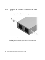
4.10.4
Installing the External I/O Expansion Unit in the Rack
A. Specifications
4–16
4–17
4–18
4–22
A–1
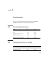
A.1
Physical Specifications
A–1
A.2
Clearance for Service Access
A.3
Environmental Specifications
A–2
A.4
Power Source Requirements
A–2
A–1
Contents
vii
A.5
Acoustic Noise Emissions.
A–3
A.6
Agency Compliance Specifications
A–3
B. External I/O Expansion Unit LED Status Indicators
B.1
LED States
B–4
C. PCI Cards and Device Mapping
C.1
Device Mapping
C.2
Device Map Examples
C.3
viii
C–1
C–3
Device Map for PCI Express Cards
C.2.2
Device Map for PCI-X Cards
C–3
C–4
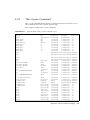
Software Commands for the External I/O Expansion Unit
C.3.1
The ioxadm Command
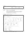
C.3.2
The show-devs Command
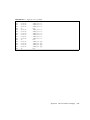
C.3.3
The cfgadm Command
C.3.4
The prtdiag Command
C–7
C–8
C–11
C–12
D–1
Troubleshooting the External I/O Expansion Unit
Glossary
Index
C–1
C.2.1
D. Troubleshooting
D.1
B–1
Glossary–1
Index–1
External I/O Expansion Unit Installation and Service Manual • June 2007
D–1
C–6
Figures
FIGURE 1-1
External I/O Expansion Unit, Front and Rear Views
1–2
FIGURE 1-2
Major Units for the External I/O Expansion Unit, Top View
FIGURE 1-3
Power Supply Unit 1–5
FIGURE 1-4
I/O Boat
FIGURE 1-5
PCI-X and PCI Express I/O Boat Layouts, Compared
FIGURE 1-6
PCI Carrier
FIGURE 1-7
Dummy Card Edge Connectors
FIGURE 1-8
Link Kits
FIGURE 1-9
Cable Management Unit for Routing Cables to Both Sides of the Rack
FIGURE 1-10
Cable Management Unit for Routing Cables Only to the Right Side of a Rack
FIGURE 1-11
Cable Plate (Side Views of Normal and Service Positions)
FIGURE 1-12
Carrier
FIGURE 1-13
Carrier Features
FIGURE 1-14
Carriers 1–19
FIGURE 1-15
Card Locks
FIGURE 1-16
Lock Arrangements for Wide and Narrow PCI cards
FIGURE 1-17
Lock Arrangements for Short PCI cards
FIGURE 1-18
Lock Arrangements for Unusually-shaped Cards
FIGURE 1-19
Excessive Force on a Lock Can Bend or Break the PCI Card
FIGURE 1-20
Card Alignment Post and Card Alignment Tab
1–3
1–7
1–8
1–11
1–12
1–13
1–14
1–15
1–16
1–17
1–18
1–20
1–23
1–24
1–25
1–26
1–27
ix
FIGURE 1-21
Card Alignment Post (Detail)
FIGURE 1-22
Internal RFI Gasket
FIGURE 1-23
Screw Hole Locations for the Carrier Slot Key
FIGURE 1-24
Optical Cables Connect TX Sockets to RX Sockets
FIGURE 1-25
LEDs on the Front of the Chassis
1–33
FIGURE 1-26
LEDs on the Rear of the Chassis
1–34
FIGURE 2-1
Mounting Kit
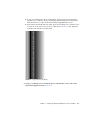
FIGURE 2-2
Typical Rack Unit Marks
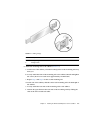
FIGURE 2-3
Installing the Chassis Lock Brackets
FIGURE 2-4
Sliding Flange 2–5
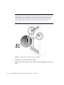
FIGURE 2-5
Installing the Mounting Brackets in a Cabinet
FIGURE 2-6
Mounting Kit
FIGURE 2-7
Typical Installation of Caged Nuts
FIGURE 2-8
Installing the Chassis Lock Brackets
FIGURE 2-9
Screws on the Sliding Flanges
FIGURE 2-10
Mounting Bracket Installation
FIGURE 2-11
Installing the External I/O Expansion Unit in the Rack
FIGURE 2-12
Installing the Support Brackets
2–15
FIGURE 2-13
Type A Cable Plate, Top View
2–16
FIGURE 2-14
Type B Cable Plate, Top View
2–16
FIGURE 2-15
Cable Plate and Support Bracket, Side View
FIGURE 2-16
AC Cables for Type A Cable Management Plate
FIGURE 2-17
AC Cables and Cords for Type B Cable Management Plate
FIGURE 2-18
TX and RX Labels on the Optical Link Cable
FIGURE 2-19
Copper Link Cable Plug
FIGURE 2-20
Copper Link Cable Ring Tab
FIGURE 3-1
Unlocking and Removing a Carrier
FIGURE 3-2
Closing the Carrier Handle
FIGURE 3-3
Screws for Card Locks
3–3
FIGURE 3-4
Inserting the PCI Card
3–4
x
1–28
1–29
1–30
1–32
2–2
2–3
2–4
2–6
2–7
2–9
2–10
2–11
2–12
2–14
2–17
2–18
2–21
2–22
2–23
3–2
3–3
External I/O Expansion Unit Installation and Service Manual • June 2007
2–19
FIGURE 3-5
Hooking the Card Notch Over the Locator Bar
3–5
FIGURE 3-6
Using Card Lock to Hold the PCI Card
FIGURE 3-7
Correct Location for an Unused Type C Card Lock
FIGURE 3-8
Excessive Pressure Bends the PCI Card Bracket
FIGURE 3-9
PCI Card and Carrier
FIGURE 3-10
Closing the Carrier Handle
FIGURE 3-11
Inserting the PCI Card
FIGURE 3-12
Hooking the Card Notch Over the Locator Bar
FIGURE 3-13
Using Card Lock to Hold the PCI Card
FIGURE 3-14
Correct Location for an Unused Type C Card Lock
FIGURE 3-15
Excessive Pressure Bends the PCI Card Bracket
FIGURE 3-16
PCI Card and Carrier
FIGURE 3-17
Example of Cable Management for the Type A Cable Plate
3–15
FIGURE 3-18
Example of Cable Management for the Type B Cable Plate
3–16
FIGURE 4-1
PSU 4–3
FIGURE 4-2
Screw Hole Locations for the Carrier Slot Key
FIGURE 4-3
Carrier Locking Latch
FIGURE 4-4
Type A Cable Plate
4–10
FIGURE 4-5
Type B Cable Plate
4–10
FIGURE 4-6
Cable Plate (Side Views of Normal and Service Positions)
FIGURE 4-7
Removing the Chassis Top Cover
FIGURE 4-8
Bezel Screws 4–20
FIGURE 4-9
Serial Number Labels
FIGURE 4-10
Uninstalling the Chassis Lock Brackets
FIGURE 4-11
Installing the External I/O Expansion Unit in the Rack
FIGURE B-1
LEDs on the Front of the Chassis
B–2
FIGURE B-2
LEDs on the Rear of the Chassis
B–3
FIGURE C-1
Device Path for PCI Express (PCIe) PCI Cards
FIGURE C-2
Device Path for PCI-X PCI Cards
3–6
3–6
3–7
3–8
3–9
3–10
3–11
3–12
3–12
3–13
3–14
4–5
4–9
4–11
4–19
4–21
4–22
4–23
C–3
C–5
Figures
xi
xii
External I/O Expansion Unit Installation and Service Manual • June 2007
Tables
TABLE 1-1
Card and Lock Styles
1–21
TABLE 1-2
Carrier Keys 1–30
TABLE 1-3
Service Information Summary
TABLE 2-1
Caged Nut Locations
TABLE 2-2
Normal PSU Indications
TABLE 4-1
Service Task Map
TABLE B-1
External I/O Expansion Unit Chassis (Front)
TABLE B-3
I/O Boat
TABLE B-4
Power Supply Unit (PSU0 and PSU1)
TABLE B-2
External I/O Expansion Unit Chassis (Rear)
TABLE B-5
Carriers 1-6
TABLE B-6
Link Card (Optical Fiber Version)
TABLE B-7
Link Card (Copper Conductor Version)
TABLE B-8
Individual PCI Card
TABLE C-1
IOU Slots in SPARC Enterprise M4000/M5000 Servers
C–2
TABLE C-2
IOU Slots in SPARC Enterprise M8000/M9000 Servers
C–2
TABLE C-3
Parts of a Device Path for a PCI Express I/O Boat
TABLE C-4
Parts of a Device Path for a PCI-X I/O Boat
TABLE C-5
Diagnostic and Maintenance Commands
TABLE C-6
PCI Cards in a Typical External I/O Expansion Unit
1–37
2–8
2–19
4–1
B–4
B–5
B–5
B–5
B–6
B–6
B–7
B–7
C–4
C–5
C–6
C–6
xiii
TABLE C-7
ioxadm Privileges and Commands
TABLE D-1
Troubleshooting
xiv
C–7
D–1
External I/O Expansion Unit Installation and Service Manual • June 2007
Preface
This manual describes the procedure for installing the External I/O Expansion Unit
on the SPARC Enterprise M4000/M5000/M8000/M9000 servers. This manual also
provides information on the proper use and maintenance of the system.
This manual is intended for engineers, system administrators, authorized service
providers (ASP), and users possessing a high degree of knowledge about hardware
troubleshooting and switching.
This section includes:
■
■
■
■
■
■
■
■
■
■
“Structure and Contents of This Manual” on page xv
“SPARC Enterprise Mx000 Servers Documentation” on page xvi
“Text Conventions” on page xix
“Prompt Notations” on page xix
“Syntax of the Command Line Interface (CLI)” on page xx
“Environment Requirements for Using This Product” on page xx
“Conventions for Alert Messages” on page xxi
“Notes on Safety” on page xxii
“Product Handling” on page xxiv
“Fujitsu Welcomes Your Comments” on page xxvi
Structure and Contents of This Manual
This manual consists of the following eight chapters.
■
Chapter 1 Overview
This chapter provides a summary of the External I/O Expansion Unit.
■
Chapter 2 Installing the External I/O Expansion Unit in a Cabinet
This chapter describes the procedure for installing the External I/O Expansion
Unit.
xv
■
Chapter 3 Working with PCI Cards
This chapter describes the procedure for mounting PCI cards.
■
Chapter 4 Servicing and Replacing Components
This chapter describes the procedure for maintaining this product.
■
Appendix A Specifications
This chapter describes the physical specifications, electrical specifications, and
installation specifications.
■
Appendix B External I/O Expansion Unit LED Status Indicators
This chapter describes the LED display.
■
Appendix C PCI Cards and Device Mapping
This chapter describes the OpenBoot™ PROM Device Tree for the External I/O
Expansion Unit.
■
Appendix D Troubleshooting
This chapter describes the troubleshooting tips.
Glossary
■
Glossary
Explains the terms used in this manual.
■
Index
Provides keywords and corresponding reference page numbers so that the
reader can easily search for items in this manual as necessary.
SPARC Enterprise Mx000 Servers
Documentation
The manuals listed below are provided for reference.
Book Titles
Manual Codes
SPARC Enterprise M4000/M5000 Servers Site Planning Guide
C120-H015
SPARC Enterprise M8000/M9000 Servers Site Planning Guide
C120-H014
SPARC Enterprise Equipment Rack Mounting Guide
C120-H016
xvi External I/O Expansion Unit Installation and Service Manual • June 2007
Book Titles
Manual Codes
SPARC Enterprise M4000/M5000 Servers Getting Started Guide
C120-E345
SPARC Enterprise M8000/M9000 Servers Getting Started Guide
C120-E323
SPARC Enterprise M4000/M5000 Servers Overview Guide
C120-E346
SPARC Enterprise M8000/M9000 Servers Overview Guide
C120-E324
Important Safety Information for Hardware Systems
C120-E391
SPARC Enterprise M4000/M5000 Servers Safety and Compliance Guide
C120-E348
SPARC Enterprise M8000/M9000 Servers Safety and Compliance Guide
C120-E326
External I/O Expansion Unit Safety and Compliance Guide
C120-E457
SPARC Enterprise M4000 Server Unpacking Guide
C120-E349
SPARC Enterprise M5000 Server Unpacking Guide
C120-E350
SPARC Enterprise M8000/M9000 Servers Unpacking Guide
C120-E327
SPARC Enterprise M4000/M5000 Servers Installation Guide
C120-E351
SPARC Enterprise M8000/M9000 Servers Installation Guide
C120-E328
SPARC Enterprise M4000/M5000 Servers Service Manual
C120-E352
SPARC Enterprise M8000/M9000 Servers Service Manual
C120-E330
External I/O Expansion Unit Installation and Service Manual
C120-E329
SPARC Enterprise M4000/M5000/M8000/M9000 Servers RCI Build
Procedure
C120-E361
SPARC Enterprise M4000/M5000/M8000/M9000 Servers Administration
Guide
C120-E331
SPARC Enterprise M4000/M5000/M8000/M9000 Servers XSCF User’s
Guide
C120-E332
SPARC Enterprise M4000/M5000/M8000/M9000 Servers XSCF Reference
Manual
C120-E333
SPARC Enterprise M4000/M5000/M8000/M9000 Servers Dynamic
Reconfiguration (DR) User’s Guide
C120-E335
SPARC Enterprise M4000/M5000/M8000/M9000 Servers Capacity on
Demand (COD) User’s Guide
C120-E336
SPARC Enterprise M4000/M5000/M8000/M9000 Servers RCI User’s Guide
C120-E360
SPARC Enterprise M4000/M5000 Servers Product Notes
C120-E347
SPARC Enterprise M8000/M9000 Servers Product Notes
C120-E325
External I/O Expansion Unit Product Notes
C120-E456
Preface
xvii
1. Manuals on the Web
The latest versions of all the SPARC Enterprise Series manuals are available at the
following websites. The latest manuals can be downloaded in a batch.
Global Site
http://www.fujitsu.com/sparcenterprise/manual/
Japanese Site
http://primeserver.fujitsu.com/sparcenterprise/manual/
Note – Product Notes is available on the website only. Please check for the recent
update on your product.
2. Documentation CD
For the Documentation CD, please contact your local sales representative.
■
SPARC Enterprise M4000/M5000 Servers Documentation CD (C120-E365)
■
SPARC Enterprise M8000/M9000 Servers Documentation CD (C120-E364)
3. Manual included on the Enhanced Support Facility x.x CD-ROM disk
■
Remote maintenance service
Book Title
Manual Code
Enhanced Support Facility User's Guide for REMCS
C112-B067
4. Provided in system
Man page of the XSCF
Note – The man page can be referenced on the XSCF shell, and it provides the same
content as the SPARC Enterprise M4000/M5000/M8000/M9000 Servers XSCF Reference
Manual.
5. Solaris Operating System Related Manuals
http://docs.sun.com
xviii External I/O Expansion Unit Installation and Service Manual • June 2007
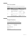
Text Conventions
This manual uses the following fonts and symbols to express specific types of
information.
Fonts/symbols
Meaning
Example
AaBbCc123
What you type, when contrasted
with on-screen computer output
XSCF> adduser jsmith
AaBbCc123
The names of commands, files, and
directories; on-screen computer
output
XSCF> showuser -p
User Name:
jsmith
Privileges:
useradm
auditadm
Italic
Indicates the name of a reference
manual
See the XSCF User's Guide.
""
Indicates names of chapters,
sections, items, buttons, or menus
See Chapter 2, "Preparation for
Installation."
Prompt Notations
The following prompt notations are used in this manual.
Shell
Prompt Notations
XSCF
XSCF>
C shell
machine-name%
C shell super user
machine-name#
Bourne shell and Korn shell
$
Bourne shell and Korn shell
super user
#
OpenBoot PROM
ok
Preface
xix
Syntax of the Command Line Interface
(CLI)
The command syntax is as follows:
■
■
■
■
■
A variable that requires input of a value must be enclosed in <>.
An optional element must be enclosed in [ ].
A group of options for an optional keyword must be enclosed in [ ] and delimited
by |.
A group of options for a mandatory keyword must be enclosed in {} and
delimited by |.
The command syntax is shown in a box.
Example:
XSCF> showuser -a
Environment Requirements for Using
This Product
This product is a computer that is intended to be used in a computer room.
xx
External I/O Expansion Unit Installation and Service Manual • June 2007
Conventions for Alert Messages
This manual uses the following conventions to show alert messages, which are
intended to prevent injury to the user or bystanders as well as property damage, and
important messages that are useful to the user.
WARNING:
This indicates a hazardous situation that could result in death or serious personal
injury (potential hazard) if the user does not perform the procedure correctly.
CAUTION:
This indicates a hazardous situation that could result in minor or moderate personal
injury if the user does not perform the procedure correctly. This signal also indicates
that damage to the product or other property may occur if the user does not perform
the procedure correctly.
IMPORTANT:
This indicates information that could help the user to use the product more
effectively.
Alert Messages in the Text
An alert message in the text consists of a signal indicating an alert level followed by
an alert statement. Alert messages are indented to distinguish them from regular
text. Also, a space of one line precedes and follows an alert statement.
WARNING:
The tasks listed below for this product and optional product provided by Fujitsu
Siemens Computers should be performed only by authorized service personnel.
Preface
xxi
The user must not perform these tasks. Incorrect operation of these tasks may cause
electric shock, injury, or fire.
■
■
■
■
■
Installation and reinstallation of all components
Removal of front, rear, or side covers
Mounting/unmounting of optional internal devices
Connecting/disconnecting of external interface cables
Maintenance (repair and regular diagnosis and maintenance)
Also, important alert messages are shown in “Important Alert Messages” on
page xxii.
Notes on Safety
Important Alert Messages
This manual provides the following important alert signals:
Caution – The WARNING signal indicates a dangerous situation could result in
death or serious injury if the user does not perform the procedure correctly.
Task
Warning
Normal
operation
Electric shock, fire
Do not damage, break, or modify the power cables. Cable damage may
cause electric shock or fire.
xxii External I/O Expansion Unit Installation and Service Manual • June 2007
Caution – The CAUTION signal indicates a hazardous situation could result in
minor or moderate personal injury if the user does not perform the procedure
correctly. This signal also indicates that damage to the product or other property
may occur if the user does not perform the procedure correctly.
Task
Warning
Normal
operation
Equipment damage
Be sure to follow the precautions below when installing the main unit.
Otherwise, the equipment may be damaged.
• Do not block ventilation slits.
• Avoid installing the equipment in a placed exposed to direct sunlight or
near equipment that becomes extremely hot.
• Avoid installing the equipment in a dusty place or a place directly
exposed to corrosive gas or salty air.
• Avoid installing the equipment in a placed exposed to strong vibration.
Also, install the equipment on a level surface so that it is stable.
• The grounding wire must be class 3 or higher. Connecting it with
another grounding wire for shared grounding may cause a malfunction.
Be sure to use a single grounding path for the grounding wire.
• Do not run any cable beneath any equipment. Also, prevent cables from
becoming taut. Never disconnect any power cable from the equipment
while power is being supplied to the equipment.
• Do not place anything on top of the main unit. Do not use the main unit
as a workspace.
• Avoid exposing the equipment to rapid changes in the ambient
temperature, such as a rapid increase during transport in winter. A
rapid increase in the ambient temperature causes moisture to condense
in the equipment. Use the equipment only after the difference between
its temperature and the ambient temperature is negligible.
• Avoid installing the equipment near a copy machine, air conditioner, or
welding machine, which is noisy.
• Take preventive action to minimize static electricity at the installation
location. Note that static electricity is easily generated in some carpets
and can cause the equipment to malfunction.
• Confirm that the power supply voltage and frequency during operation
match the rated values indicated on the equipment.
• Do not insert any object into an opening in the equipment. Components
inside the equipment use high voltage. Conductive foreign matter, such
as a metal object, inserted into the equipment, may cause a short circuit
between components, resulting in fire, electric shock, or equipment
damage.
• For maintenance of the equipment, contact your authorized service
personnel.
Preface
xxiii
Task
Warning
Normal
operation
Data destruction
Confirm the items listed below before turning off the power. Otherwise,
data may be destroyed.
• All applications have completed processing.
• No user is using the equipment.
• When the main unit power is turned off, the Power LED on the
operation panel is turned off. Be sure to confirm that the Power LED is
off before turning off the main power (uninterruptible power supply
[UPS], power distribution box, main line switch, etc.).
If necessary, back up files before turning off the system power.
Data destruction
Do not forcibly stop a domain that is operating normally. Otherwise, data
may be destroyed.
Data destruction
Do not disconnect the power cable from the AC power input while power
is being supplied. Otherwise, data stored on hard disk units may be
destroyed.
Product Handling
Maintenance
Caution – Certain tasks in this manual should only be performed by a certified
service engineer. User must not perform these tasks. Incorrect operation of these
tasks may cause electric shock, injury, or fire.
xxiv
■
Installation and reinstallation of all components, and initial settings
■
Removal of front, rear, or side covers
■
Mounting/de-mounting of optional internal devices
■
Plugging or unplugging of external interface cards
■
Maintenance and inspections (repairing, and regular diagnosis and maintenance)
External I/O Expansion Unit Installation and Service Manual • June 2007
Caution – The following tasks regarding this product and the optional products
provided from Fujitsu Siemens Computers should only be performed by a certified
service engineer. Users must not perform these tasks. Incorrect operation of these
tasks may cause malfunction.
■
Unpacking optional adapters and such packages delivered to the users
■
Plugging or unplugging of external interface cards
Remodeling/Rebuilding
Caution – Any modification and/or recycling of this product and its components
may be carried out only by a certified service engineer and must not be done by the
customer under any circumstances.
Otherwise, electric shock, injury or fire may result.
Emission of Laser Beam (Invisible)
Caution – The main unit and high-speed optical interconnect cabinet contain
modules that generate invisible laser radiation.
Laser beams are generated while the equipment is operating, even if an optical cable
is disconnected or a cover is removed.
Do not look at any light-emitting part directly or through an optical apparatus (e.g.,
magnifying glass, microscope).
Preface
xxv
Fujitsu Welcomes Your Comments
We would appreciate your comments and suggestions to improve this document.
You can submit your comments by using “Reader's Comment Form” on page xxvii.
xxvi
External I/O Expansion Unit Installation and Service Manual • June 2007
Reader's Comment Form
Preface
xxvii
FOLD AND TAPE
NO POSTAGE
NECESSARY
IF MAILED
IN THE
UNITED STATES
BUSINESS REPLY MAIL
FIRST-CLASS MAIL PERMIT NO 741 SUNNYVALE CA
POSTAGE WILL BE PAID BY ADDRESSEE
FUJITSU COMPUTER SYSTEMS
AT TENTION ENGINEERING OPS M/S 249
1250 EAST ARQUES AVENUE
P O BOX 3470
SUNNYVALE CA 94088-3470
FOLD AND TAPE
xxviii
External I/O Expansion Unit Installation and Service Manual • June 2007
CHAPTER
1
Overview
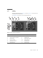
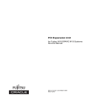
The External I/O Expansion Unit provides a host server with additional slots for PCI
cards.
■
The single I/O boat configuration provides six slots for I/O cards.
■
The optional two I/O boat configuration (FIGURE 1-1) provides twelve slots.
Note – The External I/O Expansion Unit may be described as I/O Box in programs
and manuals.
This chapter contains the following topics:
■
■
■
■
■
■
■
■
■
General Description
Card Slots
Carriers
External I/O Expansion Unit Configurations
LEDs
System Management
Site Preparation
Service Information
Electrostatic Discharge Precautions
1-1
1
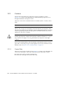
2
FIGURE 1-1
Item
1.1
External I/O Expansion Unit, Front and Rear Views
Description
1
Front View
2
Rear View
General Description
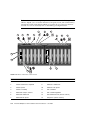
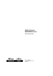
FIGURE 1-2 shows the major units for the External I/O Expansion Unit. These units
are described separately in this chapter.
Note – All slot numbers run from left to right, regardless of whether you are
viewing the front or the back of the External I/O Expansion Unit. At the front of the
External I/O Expansion Unit, the power supplies are numbered from left to right.
I/O boats at the rear of the External I/O Expansion Unit are also numbered from left
to right.
1-2
External I/O Expansion Unit Installation and Service Manual • June 2007
1
2
3
4
9
6
5
7
8
FIGURE 1-2
Item
Major Units for the External I/O Expansion Unit, Top View
Description
Item
Description
1
Chassis
6
I/O boat1
2
Power Supply Unit 1
7
Internal AC cable
3
Power Supply Unit 0
8
Cable management unit (one of two
types is available)
4
Centerplane
9
Optical link kit or Copper link kit
(two types are available)
5
I/O boat0
Chapter 1
Overview
1-3
1.1.1
Chassis
The External I/O Expansion Unit chassis includes the centerplane (item 4 in
FIGURE 1-2) and two non-removable internal AC cables (item 6 in FIGURE 1-2).
There are no serviceable components inside the chassis. If the centerplane or the
internal AC cables are damaged, the chassis must be replaced.
Note – A replacement chassis does not include power supply units (PSUs) or I/O
boats. Transfer the PSUs and I/O boats from the damaged chassis to the replacement
chassis.
Each internal AC cable supplies only one PSU. To ensure redundant power, use the
two AC cords supplied with the External I/O Expansion Unit to connect the internal
AC cables to separate AC sources.
Caution – Do not connect the internal AC cables directly to a power strip. Use the
the AC power cords supplied with the External I/O Expansion Unit to connect the
internal AC cables to electrical power.
Caution – Do not substitute other AC power cords for the AC power cords
supplied with the External I/O Expansion Unit. The substitute AC power cords may
not have the same power rating.
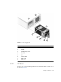
1.1.2
Power Supply Units
The External I/O Expansion Unit has two power supply units (PSUs) for
redundancy. See FIGURE 1-3.
Each PSU includes an integral fan.
1-4
External I/O Expansion Unit Installation and Service Manual • June 2007
8
7
1
6
5
4
3
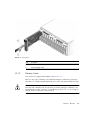
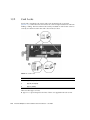
FIGURE 1-3
Item
1.1.2.1
2
Power Supply Unit
Description
1
PSU
2
Handle
3
Handle locking screw
4
AC switch
5
Fan
6
Caution labels
7
PSU slot 0
8
PSU slot 1
AC Power
The PSU slots are powered through internal AC cables that extend out of the rear of
the chassis (FIGURE 1-2).
Chapter 1
Overview
1-5
The PSUs do not share AC current. Connect both internal AC cables to AC power.
The internal AC cable for a PSU is the cable terminating nearest that PSU slot.
1.1.2.2
Fans
A fan is located in the front of each PSU. If one fan should fail, the remaining fan
supplies enough air to cool two I/O boats.
Note – The fan might turn on when you insert a PSU into the External I/O
Expansion Unit. This is normal behavior if you are installing a second PSU while the
first PSU is powered on. The fan receives DC power through the centerplane.
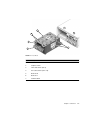
1.1.3
I/O Boats
The basic External I/O Expansion Unit configuration has one I/O boat. The second
I/O boat (Boat slot 1 in FIGURE 1-4) is an available option.
1-6
External I/O Expansion Unit Installation and Service Manual • June 2007
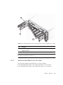
5
1
6
2
3
7
4
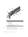
FIGURE 1-4
Item
I/O Boat
Description
1
I/O boat
2
Captive screws
3
Link card carrier (slot 0)
4
PCI card carriers (slots 1-6)
5
Boat slot 0
6
Boat slot 1
7
Caution labels
Chapter 1
Overview
1-7
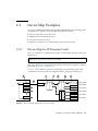
1.1.3.1
Types of I/O Boat
There are two types of I/O boat, PCI-X and PCI Express. PCI cards are not
interchangeable between the two types of boats.
■
The PCI-X I/O boat accepts PCI-X cards and some older types of PCI cards.
■
The PCI Express I/O boat accepts PCI Express cards up to x8 lanes wide. PCI
Express x16 cards do not fit in this boat.
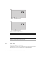
32 lane switch
32 lane switch
6 PCI-X slots
FIGURE 1-5
Slot 6
Slot 5
Slot 4
32 lane
switch
Slot 3
Slot 2
Slot 1
32 lane
switch
Link 0
Bridge
Slot 6
Bridge
Slot 4
Slot 2
Slot 1
Link 0
Bridge
Slot 5
PCI-E I/O boat
Slot 3
PCI-X I/O boat
6 PCI-E slots
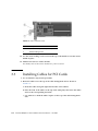
PCI-X and PCI Express I/O Boat Layouts, Compared
A PCI-X I/O boat is shown on the left side of FIGURE 1-5. This boat has six PCI-X
sockets and one link socket.
A PCI Express I/O boat is shown on the right side. There are six PCI Express sockets
and one link socket.
All PCI card data passes through the link card in the I/O boat.
A boat slot accepts either type of I/O boat.
1-8
External I/O Expansion Unit Installation and Service Manual • June 2007
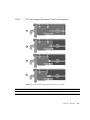
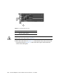
Note – When you run system diagnostics, the switches and bridges are displayed in
the output of OpenBoot™ PROM probing. However, the link cards themselves never
appear during OpenBoot PROM probing. For examples of OpenBoot PROM output,
see Appendix C.
Note – Terms: A bridge is a device that converts PCI Express and PCI-X signal
formats and connects multiple busses to a single bus. A switch is a device that
connects multiple busses to a single bus, without converting the signals to another
format.
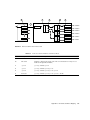
1.2
Card Slots
The card slots have the following characteristics:
■
An I/O boat has seven card slots. Slot numbers 0 through 6 are counted from left
to right.
■
Slot 0 is reserved for the link card. Slot 0 is the first slot in the left side of the I/O
boat. For information about link cards, see Section 1.2.2, “Link Kits” on page 1-12.
■
Slots 1-6 are for PCI cards. (PCI cards are sometimes known as host adapters or
host bus adapters.)
■
PCI card slots are hot-pluggable.
■
PCI-X and PCI Express sockets (FIGURE 1-5) are incompatible in length and height.
Installing a PCI-X or PCI Express card in the wrong type of I/O boat will damage
the card and the connector in the carrier slot.
■
The PCI Express I/O boat supports up to x8 card sockets. PCI Express x16 cards
are not supported in the PCI Express I/O boat.
Note – Graphics cards are not supported.
Caution – Do not insert a x16 PCI Express card in an I/O boat. The x16 card
connector is too large for the x8 card socket and will damage the socket.
Chapter 1
Overview
1-9
1.2.1
Carriers
All PCI cards in the External I/O Expansion Unit are mounted on carriers
(FIGURE 1-23). Carriers control RFI emissions and maintain the proper flow of air
through the External I/O Expansion Unit.
The front of each carrier is labelled with its slot number (PCIX 1 or PCIE 1, and so
forth).
Note – Slot 0 is reserved for the link card. This slot is marked LINK 0.
There is only one type of carrier design used in the External I/O Expansion Unit.
The same carrier fits all slots in both types of PCI-X and PCI Express boats. Note that
carriers are physically keyed to fit only specific slot numbers, but the keys can be
adjusted for other slots as needed.
Caution – If you install a PCI card when the External I/O Expansion Unit is
running, be prepared to complete the installation within two minutes or so. If you
leave a carrier slot empty for too long, the External I/O Expansion Unit might
overheat.
New carriers include dummy cards. The dummy cards help the carriers to stay in
place and to control the passage of air through the I/O boat. For information about
dummy cards, see Section 1.2.1.2, “Dummy Cards” on page 1-11.
1.2.1.1
Carrier Slots
There are seven carriers in each I/O boat (FIGURE 1-6). Carriers can be adjusted to fit
various sizes and shapes of PCI cards. Link cards use the same type of carrier.
■
■
1-10
Carrier slot 0 is always used for the link card.
Carrier slots 1 through 6 are used for PCI cards.
External I/O Expansion Unit Installation and Service Manual • June 2007
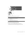
FIGURE 1-6
PCI Carrier
Item
1.2.1.2
Description
1
Carrier handle
2
Carrier locking screw
Dummy Cards
New carriers are shipped with dummy cards (FIGURE 1-7).
There are two types of dummy card, labeled PCI Express and PCI-X, respectively.
The labels also include simplified instructions for removing and installing PCI cards.
Caution – The two types of dummy cards are not interchangeable. If you replace a
PCI card with a dummy card, be sure that you use the right type of dummy card.
The differences in edge connectors on the dummy cards (FIGURE 1-7) are enough to
damage the PCI card socket on the I/O boat.
Chapter 1
Overview
1-11
PCI-E
PCI-X
FIGURE 1-7
Item
Dummy Card Edge Connectors
Description
1
PCI Express version
2
PCI-X version
Note – Be certain that the dummy cards are fully seated. This action minimizes the
vibration of unused carriers in the I/O boat slots.
1.2.2
Link Kits
One link kit is required for each I/O boat.
A link kit includes two link cards. One link card goes into the host server. The other
link card goes into the I/O boat. The link cards are physically identical.
1-12
External I/O Expansion Unit Installation and Service Manual • June 2007
Two link kit options are available, copper-conductor and optical fiber (FIGURE 1-8).
The copper-conductor link kit has one bidirectional cable. The optical link kit has
two unidirectional cables.
1
FIGURE 1-8
Item
2
Link Kits
Description
1
Copper-conductor link kit
2
Optical fiber link kit
Slot 0 in each I/O boat is the dedicated link card slot. Use slot 0 only for the link
card.
Chapter 1
Overview
1-13
1.2.3
Cable Management
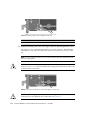
A cable management unit attaches to the rear of the system rack. There are two types
of cable management units.
■
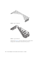
FIGURE 1-9 shows the unit used where cables can be routed to both the left and
right sides of a rack. FIGURE 3-17 shows this unit with cables.
■
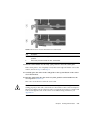
FIGURE 1-10 shows the unit used where cables can be routed only along the right
side of a rack. FIGURE 3-18 shows this unit with cables.
1
2
2
FIGURE 1-9
Item
1-14
Cable Management Unit for Routing Cables to Both Sides of the Rack
Description
1
Cable plate, type A
2
Support brackets
External I/O Expansion Unit Installation and Service Manual • June 2007
1
2
2
FIGURE 1-10
Item
Cable Management Unit for Routing Cables Only to the Right Side of a Rack
Description
1
Cable plate, type B
2
Support brackets
Note – If the PSU1 power cable doesn’t reach the rack power distribution unit, route
the cable on the left side of the rack.
1.2.3.1
Minimum Bend Radius for Link Cables
The link cables might be damaged if they are coiled too tightly.
■
The minimum bend radius for the copper link cable is 1.85 in. (47 mm).
■
The minimum bend radius for optical fiber link cables is 1.8 in. (46 mm).
Chapter 1
Overview
1-15
Caution – Coiling the link cables with a smaller bend radius than listed above will
break the cables.
1.2.3.2
Cable Management Unit
The cable management unit contains two support brackets and a cable plate.
Note – Some cable management unit configurations include two types of cable
plates.
The support brackets attach with screws to the rear of the system rack. The cable
plate rests on the support brackets.
The cable plate has two resting positions (FIGURE 1-11).
■
In the normal position, the cable plate rests on the support brackets.
■
In the raised position, the cable plate rests slightly above the support brackets.
This position provides clearance for you to remove and replace an I/O boat.
2
1
FIGURE 1-11
Item
1-16
Cable Plate (Side Views of Normal and Service Positions)
Description
1
Cable plate in the normal position (lowered)
2
Cable plate in the service position (raised)
External I/O Expansion Unit Installation and Service Manual • June 2007
1.3
Carriers
In the I/O boat, all PCI cards are mounted on carriers. When you insert the carrier
and card into the boat and push the carrier handle into the closed position, the
carrier mechanism automatically seats the PCI card.
FIGURE 1-12 shows a carrier with an attached PCI card.
Note – The service life of a carrier is at least 100 PCI card insertions. To avoid
premature failure of the carrier, do not repeatedly open and close the carrier more
than is necessary to familiarize yourself with its operation.
1
2
3
FIGURE 1-12
Carrier
Item
Description
1
PCI card
2
Carrier
3
Carrier handle in unlocked position
FIGURE 1-13 shows the details of a typical carrier.
Chapter 1
Overview
1-17
1
2
5
3
6
4
5
5
FIGURE 1-13
Item
1.3.1
Carrier Features
Description
1
Carrier main body (metal)
2
Carrier plate (plastic)
3
Carrier slot keyholes
4
Carrier handle
5
Card locks (5 are supplied with the carrier, in 3 types)
6
Turnaround area for card lock
Carrier Removal and Insertion
A carrier operates by raising or lowering a PCI card into or out of a card socket. The
vertical movement is approximately 0.4 in (10 mm).
1-18
External I/O Expansion Unit Installation and Service Manual • June 2007
A small metal latch (item 3 in FIGURE 1-14) is located at the front of the carrier. The
latch locks the carrier handle in the extended position. This action prevents the
carrier plate and PCI card from falling and damaging the PCI slot connector as you
pull the carrier unit out of the carrier slot.
After the carrier is out of the I/O boat, you can unlock the carrier handle by pushing
in the metal latch while pushing the carrier handle into its closed position. Note that
the closed position provides more vertical clearance for a PCI card when you install
or remove the PCI card.
When you insert the carrier into the I/O boat, the latch automatically unlocks itself.
3
FIGURE 1-14
Item
Carriers
Description
1
Pull carrier handle to raise PCI card out of PCI slot socket
2
Push carrier handle and latch (3) to lower PCI card into socket
Caution – All carriers must contain either a PCI card or a dummy card to avoid loss
of cooling air.
Chapter 1
Overview
1-19
1.3.2
Card Locks
A PCI card is attached to the carrier with screw-mounted locks or retainers
(FIGURE 1-15). Card locks hold a PCI card to its carrier and prevent the PCI card from
shifting or tilting. The PCI card must be securely mounted in order for the carrier to
correctly seat the PCI card in the card socket in the I/O boat.
1
2
FIGURE 1-15
Item
3
Card Locks
Description
1
Type A (Square). There are three of these.
2
Type B (S-shaped)
3
Type C (Small)
There are three types of locks:
■
1-20
Type A is a square-shaped lock. Three of these are supplied with each carrier.
External I/O Expansion Unit Installation and Service Manual • June 2007
■
Type B is an oblong lock that has an S-shaped profile. It provides a longer
extension (0.75 inch, 19mm) than type A. Type B can be used as a top or side
mount, wherever a longer reach is needed. One of this type is included with each
carrier.
■
Type C, a small quarter-round lock, can be used to support and align the bottom
of the PCI card if bottom surface of the card permits. If there is insufficient
available width (or overhang), this lock can be rotated to support the side of the
card. This lock fits only the bottom slot on the carrier. One of this type is supplied
with each carrier.
The most important functions of the locks are to secure the PCI card to the carrier
and to apply a downward force to the top of the card to seat the card in the card
socket when the carrier is inserted into the I/O boat. In addition, the locks help
prevent the card from tilting so that card edge pins line up properly with the pins in
the socket.
Because PCI card types are available in various sizes and shapes, you must choose a
combination of card locks that is best suited to the size and shape of the PCI card.
FIGURE 1-15 shows the locks for a typical PCI card (and for dummy cards).
However, cards can be much wider or narrower, or taller or shorter. FIGURE 1-16,
FIGURE 1-17, and FIGURE 1-18 show how cards can vary in height, width, and shape.
When installing a card, it might be necessary to swap locks from slot to slot in order
to find the best way to secure a PCI card to its carrier. Use TABLE 1-1 to select locks
that are best suited to your PCI card.
TABLE 1-1
Card and Lock Styles
Lock Type
PCI Card Shape
Top
Side
Bottom
Example
Wide
Type A
Type A
12 in. (304 mm) maximum
Type C
FIGURE 1-16
Average width
Type A
Type A
5.75 in. (146mm) minimum
Type B
5.0 in. (127mm) minimum
Type C
FIGURE 1-16
Narrow
Type A
Type A
5.75 in. (146mm) minimum
Type B
5.0 in. (127mm) minimum
Type C
3.0 in. (76mm) minimum
FIGURE 1-16
Chapter 1
Overview
1-21
TABLE 1-1
Card and Lock Styles (Continued)
Lock Type
PCI Card Shape
Top
Side
Very narrow
Type A
Type B
5.0 in. (127mm) minimum
Type C
3.0 in. (76mm) minimum
Tall
Type A
Type A or B
Type C
FIGURE 1-17
Low
Type A
2.0 in. (51mm) minimum
Type B
1.25 in. (31mm) minimum
Type A
5.75 in. (146mm) minimum
Type B
5.0 in. (127mm) minimum
Type C
3.0 in. (76mm) minimum
Type C
FIGURE 1-17
Very low
and narrow
Type B
1.25 in. (31mm) minimum
Type C
3.0 in. (76mm) minimum
Irregular shape
As needed
As needed
1-22
External I/O Expansion Unit Installation and Service Manual • June 2007
Bottom
Example
FIGURE 1-16
FIGURE 1-18
As needed
FIGURE 1-18
1.3.2.1
PCI Card Shapes Determine Card Lock Locations
1
2
3
4
FIGURE 1-16
Item
1
Lock Arrangements for Wide and Narrow PCI cards
Description
Wide card
2 type A on top, 1 type A on right, 1 type C on bottom
Chapter 1
Overview
1-23
Item
Description
2
Average card
2 type A on top, 1 type A on right, 1 type C on bottom
3
Narrow card
1 type A on top, 1 type A on right, 1 type C on bottom right
4
Very narrow card
1 type A on top, 1 type B on right, 1 type C on bottom right
1.3.2.2
Using Card Locks with Short PCI Cards
1
2
FIGURE 1-17
Item
1-24
Lock Arrangements for Short PCI cards
Description
Arrangement
1
Low card:
2 type A on top, 1 type A on right side, 1 type C on bottom
2
Very low card:
1 type B on top, 1 type A on right edge, 1 type C on bottom.
External I/O Expansion Unit Installation and Service Manual • June 2007
1.3.2.3
Using Card Locks with Unusual Card Shapes
1
2
FIGURE 1-18
Item
Lock Arrangements for Unusually-shaped Cards
Description
Arrangement
1
Very low and narrow card
1 type B on top, 1 type C on right side
2
Irregularly-shaped card
1 type A and 1 type B on top, 1 type A on right edge, 1 type C
on bottom.
1.3.3
PCI Card Mounting Problems
1.3.3.1
Tilted Cards
There are two common problems that involve PCI cards that turn at an angle when
mounted in PCI carriers.
■
The most common problem is that a PCI card can slip and tilt during seating
when you do not apply enough pressure on a PCI carrier card lock when
mounting the card on the carrier.
■
A less common problem is that the bracket of a PCI card will bend when you
apply too much pressure on a PCI carrier card lock when mounting the card on a
carrier.
Chapter 1
Overview
1-25
FIGURE 1-19
Item
Excessive Force on a Lock Can Bend or Break the PCI Card
Description
1
Correct
2
Incorrect
Here are some rules to avoid the tilting of PCI cards.
1. You must have at least one lock on top of the card. If the top of the card is too low
to accept a lock, the card cannot be used.
2. If you can find a lock to fit the top of the card, your next priority is to provide
side support to prevent the card from tilting. A tilted card (FIGURE 1-19) will not
seat properly.
3. Support of the bottom of the card is not a major priority because the carrier plate
itself provides some support for the bottom of the card.
4. Use only enough pressure to hold the lock against the PCI card. The bottom of the
PCI card should stay parallel with the bottom of the carrier.
1.3.3.2
Hidden Problems
Three features are located inside the front housing of the carrier. Because they are
difficult to see, they can complicate the mounting of cards on carriers.
These features are:
1-26
External I/O Expansion Unit Installation and Service Manual • June 2007
■
■
■
Card alignment post (FIGURE 1-20 and FIGURE 1-21)
Card alignment tab (FIGURE 1-20)
Internal RFI gasket (FIGURE 1-22)
Alignment Post and Alignment Tab
The card alignment post and the card alignment tab help to keep the front of the PCI
card in the correct vertical orientation, with support from properly-installed card
locks.
1
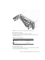
2
FIGURE 1-20
Item
Card Alignment Post and Card Alignment Tab
Description
1
Card alignment post
2
Card alignment tab
The post fits in a notch in the metal bracket of the PCI card (item 1 in FIGURE 1-20). If
you do not position the post in the notch, the card mounting bracket might bend, so
that the card lies at an angle on the carrier. The angle prevents the card from making
proper electrical contact with the socket in the I/O boat.
Chapter 1
Overview
1-27
The tab (item 2 in FIGURE 1-20) fits in a notch at the bottom of the PCI card. The tab
helps to align the card when you install it in the carrier. (Note that some card types
might not have the notch)
Note – The tab lifts the front of the card out of the card connector when you remove
the carrier from the I/O boat. If you cannot use a type C lock (FIGURE 1-15) to
support the bottom of the PCI card, the card alignment tab is the only point that can
provide support to lift the card out of the socket.
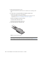
FIGURE 1-21 shows how the bracket fits over the card alignment post.
1
3
2
FIGURE 1-21
Item
1-28
Card Alignment Post (Detail)
Description
1
Carrier front housing
2
Card alignment post
3
PCI card bracket
External I/O Expansion Unit Installation and Service Manual • June 2007
Internal RFI Gasket
An RFI gasket is located inside the carrier housing, next to the card alignment post.
(A smaller RFI gasket is located on the outside of the carrier housing.) When you
insert the PCI card into the carrier, be sure that the bottom of the metal card bracket
does not scrape or loosen the bottom of the gasket (FIGURE 1-22).
The gasket material is flexible enough that you might not notice that the bracket has
dislodged the gasket. Remember to inspect the condition of this gasket before you
install the carrier in the I/O boat.
1
2
3
4
FIGURE 1-22
Internal RFI Gasket
Item
Description
1
PCI card
2
RFI gasket (extends to the bottom front of the PCI carrier)
3
Correct example: the RFI gasket lies flat
4
Incorrect example: the card bracket has hooked behind the RFI gasket
Chapter 1
Overview
1-29
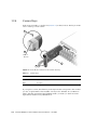
1.3.4
Carrier Keys
Each carrier is keyed to a specific slot (FIGURE 1-23) in the I/O boat. The key is an M2
screw on the top of each carrier.
4
3
4567
0123
1
2
FIGURE 1-23
Screw Hole Locations for the Carrier Slot Key
TABLE 1-2
Carrier Keys
Row Location
Hole Number
Front
0 (Link Card), 1, 2, 3
Rear
4, 5, 6, 7*
* Hole 7 is not used in current configurations.
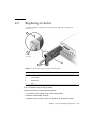
If you replace a carrier, install the key in the keyhole that corresponds to the slot that
you use. A replacement carrier includes one key. It also includes an assortment of
labels. Affix the appropriate label (LINK 0, PCIE n, or PCIX n) to the front of the
replacement carrier for easy identification.
1-30
External I/O Expansion Unit Installation and Service Manual • June 2007
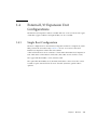
1.4
External I/O Expansion Unit
Configurations
The External I/O Expansion Unit is available with one or two I/O boats. Two types
of link kits (copper conductor and optical fiber) are also available.
1.4.1
Single Boat Configuration
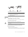
The base configuration for an External I/O Expansion Unit has a single boat, with a
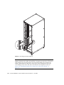
filler panel in the second boat bay. FIGURE 1-24 shows a host server and a base
External I/O Expansion Unit in the same cabinet.
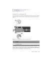
A link card in the host server connects to a link card in the External I/O Expansion
Unit. Link cables connect the two link cards. (The cables are not shown to scale.)
The copper link kit includes a 13 ft. (4 meter) cable.
The optical link kit includes 33 ft. (10 meter) link cables so that an I/O box can be
located at a place remote from host server. An 80 ft. (25 meter) optical cable is
optional.
Chapter 1
Overview
1-31
1
2
FIGURE 1-24
Item
1.4.2
Optical Cables Connect TX Sockets to RX Sockets
Description
1
External I/O Expansion Unit
2
Host server
Dual Boat Configuration
The dual boat configuration provides twelve I/O slots. Each of the I/O boats
requires its own link kit, so the host server must have two I/O slots available for this
purpose.
1-32
External I/O Expansion Unit Installation and Service Manual • June 2007
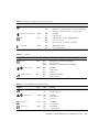
1.5
LEDs
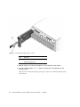
LEDs are located on the front (FIGURE 1-25) and rear (FIGURE 1-26) of the chassis and
on individual PSUs and I/O boats.
See Appendix B for information about interpreting LED states.
1
2
3
4
9
10
11
12
5
6
7
8
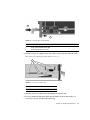
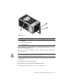
FIGURE 1-25
Item
LEDs on the Front of the Chassis
LED Description
Item
LED Description
1
Chassis locate (LED and switch)
7
PSU0 DC power
2
Chassis fault/service required
8
PSU0 AC power
3
Chassis power
9
PSU1 ready to remove
4
Chassis overtemp
10
PSU1 fault/locate
5
PSU0 ready to remove
11
PSU1 DC power
6
PSU0 fault/locate
12
PSU1 AC power
Chapter 1
Overview
1-33
Note – The Locate LED is a lighted push-button switch. When the flashing of its
LED has helped you to locate the External I/O Expansion Unit, turn off the LED by
pressing the switch. Note that the LED does not turn off if you press less than 0.5
seconds. You can also manually turn on the LED by pressing the button.
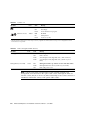
5
1
2
3
6
7
4
8
9
10
11
12
13
11
12
14
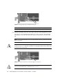
FIGURE 1-26
Item
LEDs on the Rear of the Chassis
LED Description
Item
LED Description
1
Chassis locate (LED and switch)
8
I/O boat 1 ready to remove
2
Chassis fault/service required
9
I/O boat 1 fault/locate
3
Chassis power
10
I/O boat 1 DC power
4
Chassis overtemp
11
Link card data
5
I/O boat 0 ready to remove
12
Link card management
6
I/O boat 0 fault/locate
13
Slot attention/locate (all PCI carriers)
7
I/O boat 0 DC power
14
Slot power (all PCI carriers)
1-34
External I/O Expansion Unit Installation and Service Manual • June 2007
Note – On the optical link card, the LEDs for link card data and link card
management are located next to the optical cable sockets. Although the LEDs are
near the sockets, they do not have any direct relationship to the sockets and are not
intended to indicate the activity of the optical cable sockets.
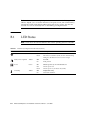
1.6
System Management
The PSUs contain temperature sensors. The PSUs can shut down automatically if
they detect an extreme temperature. The PSUs also have sensors for voltage and
current levels.
Temperature sensors are also located inside the I/O boats. FRU ID circuits are
located on the PSUs, the I/O boats, and on the chassis centerplane. Temperature
data and FRU ID information is available on an I2C bus (Inter-IC bus) in the External
I/O Expansion Unit and the link cards.
The service processor in the host system can monitor the I2C bus in the External I/O
Expansion Unit. The service processor can power down the External I/O Expansion
Unit if parameters exceed maximum limits.
There is no service processor in the External I/O Expansion Unit itself.
The ioxadm command is available on the host system to display External I/O
Expansion Unit sensor information and LED states. You can also use ioxadm to
control the Locate LEDs in the External I/O Expansion Unit and to power on or off
FRUs in the External I/O Expansion Unit. Refer to the ioxadm (8) man page for
more information.
For examples of software commands, see Appendix C.
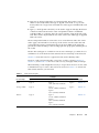
1.7
Site Preparation
The following information summarizes installation requirements for the External
I/O Expansion Unit.
For additional specifications and compliance information, see Appendix A.
Chapter 1
Overview
1-35
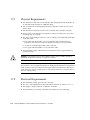
1.7.1
Physical Requirements
■
The External I/O Expansion Unit with the cable management unit attached is 19
in. (480 mm) wide and 39.4 in. (1000 mm) deep.
■
The movement of air through the External I/O Expansion Unit chassis is from
front to back.
■
The External I/O Expansion Unit is four rack units tall (7.0 inches/178 mm).
■
Service access to the External I/O Expansion Unit is from the front or rear. The
mounting rails do not slide.
■
The choice of mounting location in a rack or cabinet can be limited by the length
of the link cable:
■
■
The optical link kit includes a 33-foot/10-meter cable. The External I/O
Expansion Unit can be located some distance from the host server cabinet.
■
An 80-foot/25-meter optical link cable is optional.
■
The copper link kit includes a 13-foot/4-meter cable.
The maximum weight of the External I/O Expansion Unit is approximately 81
pounds (36.8 kg).
Caution – Mount the heaviest subassemblies at the lowest available opening to
minimize the precarious effects of a top-heavy system.
Note – Do not install another product between two External I/O Expansion Units if
the product is short in height and shorter in depth than the External I/O Expansion
Units. If there is little space between the upper and lower External I/O Expansion
Units, there may not be enough space for your hands and arms to connect cables on
the rear of the product.
1.7.2
1-36
Electrical Requirements
■
The maximum wattage per PCI card is 25 watts.
■
Two AC cords (supplied) must be used with the internal AC cables (FIGURE 1-2).
■
The supply voltage is 100 VAC to 240 VAC, 50-60 Hz.
■
The maximum power rating of External I/O Expansion Unit is 600 watts.
External I/O Expansion Unit Installation and Service Manual • June 2007
1.8
Service Information
Service and installation information is also available on service labels that are
located on the External I/O Expansion Unit top cover and on the dummy cards that
are shipped with new carriers.
TABLE 1-3
Service Information Summary
Topic
Comments
Access
• Service access to the External I/O Expansion Unit is from the
front or rear of the unit.
• The top cover is removable.
Air flow
• Air flow in the External I/O Expansion Unit is from front to
back.
• Fans are located in the power supply units. There are no
separate fans or fan trays.
• The PSU and I/O boat slots have pivoting metal flaps that drop
down to close the slots when a PSU or I/O boat is removed.
This prevents the loss of cooling air.
Mounting brackets
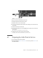
The External I/O Expansion Unit is mounted on fixed brackets.
Sliding rails are not available for this product.
PCI card installation
• To avoid overheating of the External I/O Expansion Unit, cards
should be installed as quickly as possible.
• To prepare yourself to install a card within one or two minutes,
see Section 1.3, “Carriers” on page 1-17.
PCI cable removal
• When removing cables such as LAN cables, if you have
difficulty unlatching the connector, press the latch with a
flathead screwdriver to remove the cable.
Chapter 1
Overview
1-37
TABLE 1-3
1-38
Service Information Summary (Continued)
Topic
Comments
AC cables and cords
• The internal AC cables (FIGURE 1-2) are not removable. If they
are damaged, replace the chassis.
• Each internal AC cable connects to only one PSU. Connect both
AC cables to AC power to ensure that both PSUs are
operational.
• The internal AC cables are not connected directly to AC voltage.
Use the AC power cords to connect the internal AC cables to AC
voltage.
• Do not use AC cables designed for other products with the
External I/O Expansion Unit.
Link cables
• The optical version of the link kit includes two unidirectional
cables. The ends of the cables are marked TX and RX (transmit
and receive, respectively).
• The copper link kit has one cable. The connector is designed in a
way that it cannot be connected upside down.
Jumpers
• The External I/O Expansion Unit does not have jumper pins.
• For information about any jumper pins that might be present on
a specific PCI card, see the instructions that came with the card.
External I/O Expansion Unit Installation and Service Manual • June 2007
1.9
Electrostatic Discharge Precautions
Caution – Circuit board components are vulnerable to damage by electrostatic
discharge (ESD). An electrostatic charge can build up on the human body and then
discharge when you touch a board. Such discharge can be produced by walking
across a carpet and touching a board, or by other similar cause. Before handling any
board, make sure you dissipate your body s charge. Touch a conductive surface of
the chassis or other element connected to common earth ground to discharge the
static electricity present in your body. To minimize risk of ESD damage
■
■
■
Handle board by edges only
Store board in antistatic bag provide
Use a grounding strap and an ESD mat whenever you work on a board.
Chapter 1
Overview
1-39
1-40
External I/O Expansion Unit Installation and Service Manual • June 2007
CHAPTER
2
Installing the External I/O
Expansion Unit in a Cabinet
The following topics are in this chapter:
■
■
■
■
■
■
■
■
■
2.1
Section 2.1, “Tools” on page 2-1
Section 2.2, “Installing the Rails in a Type S Rack” on page 2-2
Section 2.3, “Installing the Rails in a Type F Rack and the SPARC Enterprise 8000
Server” on page 2-7
Section 2.4, “Installing the External I/O Expansion Unit in the Cabinet” on
page 2-13
Section 2.5, “Installing the Cable Management Unit” on page 2-14
Section 2.6, “Installing the AC Cords” on page 2-17
Section 2.7, “Installing the Link Kit” on page 2-20
Section 2.7.1, “Installing the Optical Link Kit” on page 2-20
Section 2.7.2, “Installing the Copper Link Kit” on page 2-21
Tools
You need the following tools for this installation:
■
■
■
■
Phillips No. 2 screwdriver
Phillips No. 1 screwdriver
ESD-protected mat and a grounding strap
(Suggested) digital voltmeter to verify correct grounding
2-1
2.2
Installing the Rails in a Type S Rack
The External I/O Expansion Unit mounting kit (FIGURE 2-1) includes a right-side
mounting rail and a left-side mounting rail. The mounting rails are shipped
assembled. The mounting kit includes two chassis lock brackets and an assortment
of screws and caged nuts.
1
2
3
4
FIGURE 2-1
Item
Mounting Kit
Description
1
Left mounting bracket
2
Right mounting bracket
3
Left chassis lock bracket
4
Right chassis lock bracket
1. Use an antistatic strap for this procedure.
2. Locate a suitable mounting location in the cabinet.
2-2
■
The External I/O Expansion Unit occupies a height of four rack units (7 in./178
mm).
■
Mount the heaviest subassemblies at the lowest available opening to minimize the
precarious effects of a top-heavy system.
External I/O Expansion Unit Installation and Service Manual • June 2007
■
If you are installing more than one External I/O Expansion Unit, install them
together. Do not install a shorter subassembly between External I/O Expansion
Unit where the rear of the shorter subassembly might difficult to reach.
■
If the cabinet is marked with rack units, place the mounting rail so that the lower
screw hole on the rail is one hole above a RU mark (FIGURE 2-2). This aligns the
mounting rail with the lower RU mark.
FIGURE 2-2
Typical Rack Unit Marks
3. Using no. 2 Phillips screws, attach the chassis lock brackets to the sides of the
External I/O Expansion Unit (FIGURE 2-3).
Chapter 2
Installing the External I/O Expansion Unit in a Cabinet
2-3
FIGURE 2-3
Installing the Chassis Lock Brackets
4. Loosen the screws (FIGURE 2-4) that hold the sliding flanges to the mounting rails.
This action allows the rear flanges to adjust to fit different rack depths.
2-4
External I/O Expansion Unit Installation and Service Manual • June 2007
1
2
FIGURE 2-4
Item
Sliding Flange
Description
1
Sliding flange
2
Flange crews
5. Attach the mounting rails to the cabinet (FIGURE 2-5):
a. At the front of the cabinet, orient the hooked portion of the mounting rail away
from you.
b. Loosely attach the front of the mounting rail to the cabinet. (Install and tighten
the screws, then loosen each screw approximately one-half turn.)
c. Repeat Step a and Step b for the second mounting rail.
d. At the rear of the cabinet, slide the end of each mounting rail to fit the depth of
the cabinet.
e. Loosely attach the rear ends of the mounting rails to the cabinet.
f. Narrow the space between the rear ends of the mounting rails by sliding the
ends of the rails toward each other.
Chapter 2
Installing the External I/O Expansion Unit in a Cabinet
2-5
Note – At the front of the cabinet, the space between the rails should be equal to or
slightly wider than the width of the External I/O Expansion Unit chassis. At the rear
of the cabinet, the space between the rails should be slightly narrower than the
width of the External I/O Expansion Unit chassis. This arrangement allows the
correct fitting of the rails to the sides of the External I/O Expansion Unit. See
Section 2.4, “Installing the External I/O Expansion Unit in the Cabinet” on
page 2-13.
FIGURE 2-5
Installing the Mounting Brackets in a Cabinet
6. Tighten the screws at the front of the cabinet.
7. Verify that the rails at the rear of the cabinet can still slide slightly to the left and
right.
2-6
External I/O Expansion Unit Installation and Service Manual • June 2007
2.3
Installing the Rails in a Type F Rack and
the SPARC Enterprise 8000 Server
The External I/O Expansion Unit mounting kit (FIGURE 2-6) includes right-side and
left-side mounting rails. The mounting rails are shipped assembled. The mounting
kit includes two chassis lock brackets and an assortment of screws and caged nuts.
1
2
3
4
FIGURE 2-6
Item
Mounting Kit
Description
1
Left mounting bracket
2
Right mounting bracket
3
Left chassis lock bracket
4
Right chassis lock bracket
1. Use an antistatic strap for this procedure.
2. Locate a suitable mounting location in the rack or the cabinet.
■
The External I/O Expansion Unit occupies a height of four rack units (7 in./178
mm).
Chapter 2
Installing the External I/O Expansion Unit in a Cabinet
2-7
■
For safety, mount the heaviest subassemblies at the lowest available opening to
minimize the precarious effects of a top-heavy system.
■
If you are installing more than one External I/O Expansion Unit, install them
together. Do not install a shorter subassembly between External I/O Expansion
Unit where the rear of the shorter subassembly might difficult to reach.
3. Install caged nuts in the rack pillars.
TABLE 2-1 lists the rack rail locations for the caged nuts.
TABLE 2-1
Caged Nut Locations
Rack Unit
Hole #
4
12
Front
Rear
Caged nut
Caged nut
6
Caged nut
Caged nut
5
Caged nut
Caged nut
Caged nut
Caged nut
11
10
3
9
8
7
2
4
1
3
2
1
2-8
External I/O Expansion Unit Installation and Service Manual • June 2007
4 Rack unit
FIGURE 2-7
Typical Installation of Caged Nuts
4. Using no. 2 Phillips screws, attach the chassis lock brackets to the sides of the
External I/O Expansion Unit (FIGURE 2-8).
Chapter 2
Installing the External I/O Expansion Unit in a Cabinet
2-9
FIGURE 2-8
Installing the Chassis Lock Brackets
5. Loosen the screws (FIGURE 2-9) that hold the sliding flanges to the mounting rails.
This action allows the rear flanges to adjust to fit different rack depths.
2-10
External I/O Expansion Unit Installation and Service Manual • June 2007
1
2
FIGURE 2-9
Item
Screws on the Sliding Flanges
Description
1
Sliding flange
2
Flange crews
6. Attach the mounting rails to the rack (FIGURE 2-10):
a. At the front of the cabinet, orient the hooked portion of the mounting rail away
from you.
b. Loosely attach the front of the mounting rail to the cabinet. (Install and tighten
the screws, then loosen each screw approximately one-half turn.)
c. Repeat Step a and Step b for the second mounting rail.
d. At the rear of the cabinet, slide the end of each mounting rail to fit the depth of
the cabinet.
e. Loosely attach the rear ends of the mounting rails to the cabinet.
f. Narrow the space between the rear ends of the mounting rails by sliding the
ends of the rails toward each other.
Chapter 2
Installing the External I/O Expansion Unit in a Cabinet
2-11
FIGURE 2-10
Mounting Bracket Installation
Note – At the front of the cabinet, the space between the rails should be equal to or
slightly wider than the width of the External I/O Expansion Unit chassis. At the rear
of the cabinet, the space between the rails should be slightly narrower than the
width of the External I/O Expansion Unit chassis. This arrangement allows the
correct fitting of the rails to the sides of the External I/O Expansion Unit. See
Section 2.4, “Installing the External I/O Expansion Unit in the Cabinet” on
page 2-13.
2-12
External I/O Expansion Unit Installation and Service Manual • June 2007
7. Tighten the screws at the front of the cabinet.
8. Verify that the rails at the rear of the cabinet can still slide slightly to the left and
right.
2.4
Installing the External I/O Expansion
Unit in the Cabinet
1. Use an antistatic strap for this procedure.
2. Place the External I/O Expansion Unit on the front of the mounting rails and slide
the External I/O Expansion Unit into the cabinet.
As you slide the External I/O Expansion Unit into the cabinet, the sides of the
External I/O Expansion Unit chassis push the ends of the rails apart from each other.
When the chassis is almost completely in the cabinet, bulges on the underside of the
chassis contact hooks that are located on the mounting rails, wedging the mounting
rails tightly against the sides of the chassis. This wedging action stabilizes the
External I/O Expansion Unit and is necessary to reduce the amount of vibration that
occurs when the system is running.
3. Tighten the screws at the rear of the mounting rails.
4. Lock the front of the External I/O Expansion Unit in place with two screws on each
side (FIGURE 2-11).
Chapter 2
Installing the External I/O Expansion Unit in a Cabinet
2-13
FIGURE 2-11
2.5
Installing the External I/O Expansion Unit in the Rack
Installing the Cable Management Unit
At the rear of the cabinet, install the cable management support brackets:
1. Use an antistatic strap for this procedure.
2. Place the support brackets just above the chassis mounting brackets (FIGURE 2-12)
and loosely attach the support brackets to the cabinet with two screws each.
Do not tighten the screws yet.
2-14
External I/O Expansion Unit Installation and Service Manual • June 2007
FIGURE 2-12
Installing the Support Brackets
Note – The cable management unit includes one Type A cable plate (FIGURE 2-13).
Some configurations also include a type B cable plate (FIGURE 2-14).
3. Place the cable plate between the support brackets (FIGURE 2-15).
On each side of the cable plate, the forward tab rests on the bottom of the large
cutout in the support bracket. The rear tab rests in a small depression in the top of
the support bracket. This is the normal operating position for the cable plate.
Chapter 2
Installing the External I/O Expansion Unit in a Cabinet
2-15
2-16
FIGURE 2-13
Type A Cable Plate, Top View
FIGURE 2-14
Type B Cable Plate, Top View
External I/O Expansion Unit Installation and Service Manual • June 2007
1
2
3
FIGURE 2-15
Item
Cable Plate and Support Bracket, Side View
Description
1
Cable plate
2
Support bracket
3
Supporting tabs on the cable plate
4. Tighten the green cable plate locking screws at each side of the cable plate.
5. Tighten the mounting screws on the support brackets.
2.6
Installing the AC Cords
1. Use an antistatic strap for this procedure.
2. Attach an AC cord to an internal AC cable at the rear of the External I/O
Expansion Unit, then connect the AC cord to an AC outlet.
Note – Do not attempt to connect the internal AC cable directly to an AC socket
(power distribution unit or power strip). You must use one of the AC cords supplied
with the External I/O Expansion Unit.
3. Attach an AC cord to the remaining internal AC cable as in Step 2.
Chapter 2
Installing the External I/O Expansion Unit in a Cabinet
2-17
Note – The fan might turn on when you insert a power supply into the External I/O
Expansion Unit. This is normal behavior if you are replacing a PSU while the other
PSU is powered up.
1
2
1
2
FIGURE 2-16
AC Cables for Type A Cable Management Plate
Item
2-18
Description
1
Internal AC cables
2
AC cords
External I/O Expansion Unit Installation and Service Manual • June 2007
FIGURE 2-17
AC Cables and Cords for Type B Cable Management Plate
4. Turn on the PSU AC switches.
The switches are located on the front of the power supplies.
The LEDs on the power supplies should display the following indications after a
short initialization period.
TABLE 2-2
Normal PSU Indications
LED
Indication
AC Power
On (green LED)
DC Power
On (green LED)
For other LED combinations, see TABLE B-4.
5. Turn off the PSU AC switches.
The LEDs on the PSUs continue glowing until DC current in the PSUs is depleted.
This can take approximately five to ten seconds.
Chapter 2
Installing the External I/O Expansion Unit in a Cabinet
2-19
2.7
Installing the Link Kit
A link kit includes two identical link cards, one for the host server and one for the
I/O boat. You can install either card in either location.
The link card in the I/O boat is always installed in boat slot 0. If your External I/O
Expansion Unit has two I/O boats, then link cards must be located in slot 0 of both
boats.
Your link kit is one of two types:
2.7.1
■
Optical circuitry and two cables — see Section 2.7.1, “Installing the Optical Link
Kit” on page 2-20
■
Copper conductor circuitry and one cable — see Section 2.7.2, “Installing the
Copper Link Kit” on page 2-21
Installing the Optical Link Kit
Note – The minimum bend radius for optical fiber link cables is 1.8 in. (46 mm).
1. Use an antistatic strap for this procedure.
2. Install a link card in the host server.
See the service manual for your host server for instructions for installing an PCI
card.
3. If a link card is not already installed in the I/O boat, install it now.
a. Remove the carrier in slot 0 of the I/O boat.
Slot 0 is the leftmost slot in the boat. For details about card removal and
replacement, see Section 3.1, “Installing a PCI Card” on page 3-1.
b. Remove the dummy card from the carrier.
c. Install the link card in the carrier.
d. Install the carrier and link card in slot 0.
4. Install the link cables.
2-20
External I/O Expansion Unit Installation and Service Manual • June 2007
Note – The two optical link cables are identical. One end of a cable is marked TX.
The other end is marked RX (FIGURE 2-18). When you route the cables, ensure that the
TX plug of one cable is paired with the RX plug of the other cable.
a. At the I/O boat, connect a plug marked TX into the TX port on the link card.
Connect the RX plug of the second cable into the RX port.
b. At the host server, connect a plug marked TX to the TX port on the link card.
Connect the RX plug of the remaining cable into the RX port.
1
2
FIGURE 2-18
Item
TX and RX Labels on the Optical Link Cable
Description
1
TX label
2
RX label
Note – Check the labels to verify that each plug is connected to the correct port. The
TX and RX plugs are identically shaped, so it is easy to incorrectly connect a plug to
the wrong port.
2.7.2
Installing the Copper Link Kit
Note – The minimum bend radius for the copper link cable is 1.85 in. (47 mm).
1. Use an antistatic strap for this procedure.
Chapter 2
Installing the External I/O Expansion Unit in a Cabinet
2-21
2. Install a link card in the host server.
See the service manual for your host server for instructions for installing an PCI
card.
3. If a link card is not already installed in the I/O boat, install it now.
a. Remove the carrier in slot 0 of the I/O boat.
Slot 0 is the leftmost slot in the boat. For details about card removal and
replacement, see Section 3.1, “Installing a PCI Card” on page 3-1.
b. Remove the dummy card from the carrier.
c. Install the link card in the carrier.
d. Install the carrier and link card in slot 0.
4. Connect the link cable to both link cards.
FIGURE 2-19
Copper Link Cable Plug
Note – If it is necessary to disconnect a link cable, pull the ring-shaped tab
approximately 0.15 inch (2mm) in the direction shown by the arrow in FIGURE 2-20.
2-22
External I/O Expansion Unit Installation and Service Manual • June 2007
Caution – Do not pull the ring tab more than 0.15 inch (2mm), or it will break.
When disconnecting the cable from a link card, pull the cable plug while pulling
carefully on the ring tab.
FIGURE 2-20
Copper Link Cable Ring Tab
Chapter 2
Installing the External I/O Expansion Unit in a Cabinet
2-23
2-24
External I/O Expansion Unit Installation and Service Manual • June 2007
CHAPTER
3
Working with PCI Cards
This chapter gives procedures for installing PCI and link cards, and related cables.
■
■
■
3.1
Section 3.1, “Installing a PCI Card” on page 3-1
Section 3.2, “Replacing a PCI Card” on page 3-8
Section 3.3, “Installing Cables for PCI Cards” on page 3-14
Installing a PCI Card
1. Determine which card locks you will use to mount your PCI card on a carrier.
The size and shape of the PCI card affect the quantity and type of card locks you
use. Before you start this procedure, you must decide which locks you will use for
the PCI card. See Section 1.3.2, “Card Locks” on page 1-20
Caution – If you install a PCI card while the External I/O Expansion Unit is
running, be prepared to complete the installation in approximately two minutes. If
you leave a carrier slot empty for too long, the External I/O Expansion Unit might
overheat.
2. Use an antistatic strap for this procedure.
3. Unscrew the retaining screw on the carrier handle (item 1 in FIGURE 3-1), then pull
out the carrier handle approximately four inches (100 mm).
3-1
FIGURE 3-1
Unlocking and Removing a Carrier
Item
Description
1
Carrier handle
2
Carrier locking screw
4. Pull the carrier out of the slot and place it on an antistatic work surface.
5. Press the locking latch (FIGURE 3-2) while you push the carrier handle into the
closed position.
This action lowers the carrier plate, giving you room to move the PCI card into place
on the carrier.
3-2
External I/O Expansion Unit Installation and Service Manual • June 2007
1
2
FIGURE 3-2
Item
Closing the Carrier Handle
Description
1
Push carrier handle to the right
2
Push locking latch to the left
6. Place the carrier on a padded static-safe surface and loosen the card lock screws.
The screws are on the back of the carrier (FIGURE 3-3).
1
FIGURE 3-3
Item
1
Screws for Card Locks
Description
Card lock screws
7. Turn the carrier over and remove the dummy card or PCI card.
8. For very small PCI cards (1.25 in./31 mm tall and/or 3.0 in./76 mm wide), it is
necessary to do one or both of the following:
Chapter 3
Working with PCI Cards
3-3
■
Move the long card lock from the horizontal slider slot to the front vertical slider
slot, then slide it down to reach the top of the PCI card.
■
Rotate the fourth card lock 270 degrees counterclockwise from its parking
position and slide it to the rear edge of the PCI card.
9. Place the PCI card on the carrier.
a. Place the front of the card inside the housing (FIGURE 3-4).
1
FIGURE 3-4
Item
1
Inserting the PCI Card
Description
See the caution, below.
Caution – Do not allow the bottom edge of the PCI card bracket to tear the RFI
gasket in the front of the carrier (FIGURE 3-4).
b. Hook the notch (item 3 in FIGURE 3-5) on the bottom front of the card over the
locator bar (item 4 in FIGURE 3-5). The locator bar is part of the bottom left
corner of the carrier plate.
3-4
External I/O Expansion Unit Installation and Service Manual • June 2007
FIGURE 3-5
Item
Hooking the Card Notch Over the Locator Bar
Description
1
Carrier locking handle (in closed position)
2
PCI card
3
Notch on bottom of PCI card
4
Detail of locator bar on the moveable plate
10. Attach the PCI card to the carrier with one card lock:
a. Slide a card lock to the right edge of the PCI card.
b. Hold the card in place and partially tighten the card lock screw.
c. Verify that the PCI card is not tilted, then tighten the card lock screw.
Chapter 3
Working with PCI Cards
3-5
1
FIGURE 3-6
Item
1
Using Card Lock to Hold the PCI Card
Description
Card lock
11. Slide the remaining card locks to the edges of the PCI card and tighten the screws.
The shape of a PCI card might prevent the use of some card locks. The minimum
requirement is one card lock on the side of the PCI card and one card lock on the
top.
Note – If the card lock screws are loose, the card locks will slip. The PCI card will
not seat properly.
Caution – If the bottom card lock (Type C) is not used, leave it at the far right side
of the slot (FIGURE 3-7). The PCI card will not seat properly if the bottom of the card
lock touches the card socket.
1
FIGURE 3-7
Correct Location for an Unused Type C Card Lock
Caution – Do not apply excessive pressure on the upper card locks. Too much
pressure will bend the PCI card bracket. See FIGURE 3-8.
3-6
External I/O Expansion Unit Installation and Service Manual • June 2007
FIGURE 3-8
Item
Excessive Pressure Bends the PCI Card Bracket
Description
1
Moderate pressure on an upper card lock holds the PCI card in a horizontal
position.
2
Excessive pressure bends the PCI card bracket
12. Pull the carrier handle into the fully open position to raise the carrier plate.
If the carrier plate is not completely raised, the bottom edge will hit the card socket
in the I/O boat in Step 13 and Step 14.
13. Carefully place the replacement carrier in the card guides at the top and bottom of
the carrier slot in the I/O boat.
14. Push the carrier fully into the carrier slot, then push the carrier handle into the
closed position (FIGURE 3-9).
This action seats the PCI card in the card socket.
Caution – If the carrier handle does not close easily, the PCI card might not be
seating properly in the card socket in the I/O boat. Remove the carrier and inspect
the PCI card. If the bottom of the PCI card is not perfectly horizontal, loosen the card
locks and realign the card on the carrier. For troubleshooting information, see
Appendix D
Chapter 3
Working with PCI Cards
3-7
FIGURE 3-9
Item
PCI Card and Carrier
Description
1
Carrier handle (in closed position)
2
Carrier locking screw
15. Use the carrier locking screw located on the top of the handle to lock the carrier
handle in place.
16. Add the PCI card to a Solaris domain.
For details, refer to the service manual for your host server.
3.2
Replacing a PCI Card
Caution – If you install a PCI card while the External I/O Expansion Unit is
running, be prepared to complete the installation in approximately two minutes. If
you leave a carrier slot empty for too long, the External I/O Expansion Unit might
overheat.
1. Use an antistatic strap for this procedure.
2. Remove the PCI card from the Solaris domain.
For details, refer to the service manual for your host server.
3. Remove the carrier from the carrier slot in the I/O boat.
a. Loosen the carrier locking screw on the carrier handle.
b. Pull the carrier handle out fully.
3-8
External I/O Expansion Unit Installation and Service Manual • June 2007
c. Pull the carrier out of the carrier slot and place on an antistatic surface.
4. Press the locking latch (FIGURE 3-10) while you push the carrier handle into the
closed position.
This action lowers the PCI card, facilitating the replacement of the card.
1
2
FIGURE 3-10
Item
Closing the Carrier Handle
Description
1
Push carrier handle to the right
2
Push locking latch to the left
5. Remove the existing card from the carrier.
6. If you are installing an exact replacement, go to Step 8.
7. For very small PCI cards (1.25 in./31 mm tall and/or 3.0 in./76 mm wide), it is
necessary to do one or both of the following:
■
Move the long card lock from the horizontal slider slot to the front vertical slider
slot, then slide it down to reach the top of the PCI card.
■
Rotate the fourth card lock 270 degrees counterclockwise from its parking
position and slide it to the rear edge of the PCI card.
8. Place the PCI card on the carrier.
a. Place the front of the card inside the housing (FIGURE 3-11).
Chapter 3
Working with PCI Cards
3-9
1
FIGURE 3-11
Item
1
Inserting the PCI Card
Description
See the caution, below.
Caution – Do not allow the bottom edge of the PCI card bracket to tear the RFI
gasket in the front of the carrier (FIGURE 3-4).
b. Hook the notch (item 3 in FIGURE 3-12) on the bottom front of the card over the
locator bar (item 4 in FIGURE 3-12). The locator bar is part of the bottom left
corner of the carrier plate.
3-10
External I/O Expansion Unit Installation and Service Manual • June 2007
FIGURE 3-12
Item
Hooking the Card Notch Over the Locator Bar
Description
1
Carrier locking handle (in closed position)
2
PCI card
3
Notch on bottom of PCI card
4
Detail of locator bar on the moveable plate
9. Attach the PCI card to the carrier with one card lock:
a. Slide a card lock to the right edge of the PCI card.
b. Hold the card in place and partially tighten the card lock screw.
c. Verify that the PCI card is not tilted, then tighten the card lock screw.
Chapter 3
Working with PCI Cards
3-11
1
FIGURE 3-13
Item
1
Using Card Lock to Hold the PCI Card
Description
Card lock
10. Slide the remaining card locks to the edges of the PCI card and tighten the screws.
The shape of a PCI card might prevent the use of some card locks. The minimum
requirement is one card lock on the side of the PCI card and one card lock on the
top.
Note – If the card lock screws are loose, the card locks will slip and the PCI card
will not seat properly.
Caution – If the bottom card lock (Type C) is not used, leave it at the far right side
of the slot (FIGURE 3-14). The PCI card will not seat properly if the bottom of the card
lock touches the card socket.
1
FIGURE 3-14
Correct Location for an Unused Type C Card Lock
Caution – Do not apply excessive pressure on the upper card locks. Too much
vertical pressure will bend the PCI card bracket. See FIGURE 3-15.
3-12
External I/O Expansion Unit Installation and Service Manual • June 2007
FIGURE 3-15
Item
Excessive Pressure Bends the PCI Card Bracket
Description
1
Moderate pressure on an upper card lock holds the PCI card in a horizontal
position.
2
Excessive pressure bends the PCI card bracket
11. Pull the carrier handle into the fully open position to raise the carrier plate.
If the carrier plate is not completely raised, the bottom edge will hit the card socket
in the I/O boat in Step 12 and Step 13.
12. Carefully place the carrier in the card guides at the top and bottom of the carrier
slot in the I/O boat.
13. Push the carrier fully into the carrier slot, then push the carrier handle into the
closed position (FIGURE 3-9).
This action seats the PCI card in the card socket.
Caution – If the carrier handle does not close easily, the PCI card might not be
seating properly in the card socket in the I/O boat. Remove the carrier and inspect
the PCI card. If the bottom of the PCI card is not perfectly horizontal, loosen the card
locks and realign the card on the carrier. For troubleshooting information, see
Appendix D
Chapter 3
Working with PCI Cards
3-13
FIGURE 3-16
Item
PCI Card and Carrier
Description
1
Carrier handle (in closed position)
2
Carrier locking screw
14. Use the carrier locking screw located on the top of the handle to lock the carrier
handle in place.
15. Add the PCI card to a Solaris domain.
For details, refer to the service manual for your host server.
3.3
Installing Cables for PCI Cards
1. Use an antistatic strap for this procedure.
2. Route the cables across the top of the cable management unit as shown in
FIGURE 3-17.
a. Route the cables along the right and left sides of the cabinet.
b. Place the ends of the cables on the top of the cable plate, then curve the cables
down to the corresponding PCI cards.
c. Use cable ties to hold the cables in place on the top of the cable management
unit.
3-14
External I/O Expansion Unit Installation and Service Manual • June 2007
Note – Before tightening the cable ties, ensure that each cable has a service loop
(freedom of movement) of at least 2 inches (50mm). This allows the cable plate and
cables to be moved from the normal position (FIGURE 4-6) to the service position
without the need to untie the cables.
FIGURE 3-17
Example of Cable Management for the Type A Cable Plate
Chapter 3
Working with PCI Cards
3-15
FIGURE 3-18
Example of Cable Management for the Type B Cable Plate
3. Attach I/O cables from the PCI cards and their respective devices or network
ports.
3-16
External I/O Expansion Unit Installation and Service Manual • June 2007
CHAPTER
4
Servicing and Replacing
Components
This chapter includes the service procedures for replacing field-replaceable units and
installing optional assemblies.
For a list of service procedures, see the task map (TABLE 4-1).
4.1
TABLE 4-1
Task Map
Service Task Map
FRU
Task
Comments
PCI card
• Install a new PCI card
Section 3.1, “Installing a PCI Card” on page 3-1
• Replace an existing PCI card
Section 3.2, “Replacing a PCI Card” on page 3-8
PSU
• Replace a PSU
Section 4.2, “Replacing a Power Supply Unit” on
page 4-2
Carrier
• Replace a carrier
Section 4.3, “Replacing a Carrier” on page 4-5
Link
• Replace a link cable
Section 4.4, “Replacing a Link Cable” on page 4-7
• Replace a link card in a host server
Section 4.5, “Replacing a Link Card in the Host
Server” on page 4-7
• Replace a link card in the I/O boat
Section 4.6, “Replacing a Link Card in an I/O Boat”
on page 4-8
Cable
Management
• Prepare the cable plate for I/O boat Section 4.7, “Preparing the Cable Plate for Service”
service
on page 4-9
4-1
TABLE 4-1
Service Task Map
FRU
Task
Comments
I/O boat
• Install a second I/O boat
Section 4.8, “Installing a Second I/O Boat” on
page 4-11
• Replace an I/O boat
Section 4.9.1, “Replacing a Boat in a Single Boat
Configuration” on page 4-13
• Replace an I/O boat
Section 4.9.2, “Replacing a Boat in a Dual Boat
Configuration” on page 4-14
Replace the External I/O Expansion
Unit chassis
Section 4.10, “Replacing the External I/O Expansion
Unit Chassis” on page 4-16.
Chassis
4.2
Replacing a Power Supply Unit
1. Use an antistatic strap for this procedure.
2. Unpack the new power supply unit and set it flat on an antistatic surface.
Caution – Do not rest a PSU vertically. The plastic electrical connector on the back
is breakable.
3. At the front of the defective PSU, turn off the PSU AC switch.
4. Loosen the handle locking screw on the PSU handle.
Caution – The PSU is heavy (7.5 lb/3.4 kg).
5. Unlock the PSU by swinging the handle out 90 degrees into the fully open
position. (FIGURE 4-1)
4-2
External I/O Expansion Unit Installation and Service Manual • June 2007
1
2
3
FIGURE 4-1
Item
PSU
Description
1
Handle
2
Handle locking screw
3
Warning labels
6. Place a hand under the PSU to prevent it from falling, then pull the PSU out of
the External I/O Expansion Unit.
When you can see the warning label on the top of the PSU, the PSU is almost fully
out of the PSU slot.
Caution – Do not allow the rear of the PSU to drop. The connector at the rear of the
PSU can be damaged if it strikes the edge of the slot.
A pivoting flap behind the External I/O Expansion Unit drops down to prevent loss
of cooling air.
7. Set the PSU flat on an antistatic surface.
8. Insert the new PSU into the External I/O Expansion Unit.
The pivoting flap automatically swings up and out of the way.
Chapter 4
Servicing and Replacing Components
4-3
Note – The fan in the new PSU turns on immediately if the External I/O Expansion
Unit is running.
9. Turn the PSU handle 90 degrees into the closed position.
10. Secure the handle locking screw on the PSU handle.
11. Turn on the AC switch on the PSU.
The Fault/Locate LED (
) lights up momentarily during the initialization then
turns off. You should see the AC power (
) and DC power (
) LEDs turn on
during the initialization.
For other LED indications, see Appendix B.
4-4
External I/O Expansion Unit Installation and Service Manual • June 2007
4.3
Replacing a Carrier
A carrier is keyed to a specific slot in an I/O boat. The key is an M2 screw
(FIGURE 4-2).
4
3
4567
0123
1
2
FIGURE 4-2
Item
Screw Hole Locations for the Carrier Slot Key
Description
1
Carrier
2
Carrier label
3
Keyholes 0-7
4
Key
1. Use an antistatic strap for this procedure.
2. Remove the defective carrier from the I/O boat.
a. Loosen the carrier locking screw on the carrier handle.
b. Pull the carrier handle out fully.
c. Pull the carrier out of the carrier slot and place on an antistatic surface.
Chapter 4
Servicing and Replacing Components
4-5
3. Install an M2 screw on the replacement carrier, in the key hole that corresponds to
the slot number of the defective carrier.
4. Mark the carrier with the slot name and number.
The replacement carrier includes an assortment of adhesive labels including LINK 0,
PCIX 1, PCIE 1, and so forth. Use the replacement label that corresponds to the label
on the defective carrier. Place the label just below the opening in the front of the
carrier (FIGURE 4-2).
5. Transfer the PCI card from the defective carrier to the replacement carrier.
a. Remove the dummy card from the replacement carrier by loosening the Phillips
screws on the card locks.
b. Examine the defective carrier and determine which card locks on the
replacement carrier will be used. Move the card locks on the replacement
carrier to approximately the same locations as on the defective carrier.
One or more card locks on the replacement carrier might not be needed. Move the
unused card locks out of the way or else remove them entirely from the carrier.
c. Unlock the PCI card from the defective carrier and install the card on the
replacement carrier.
6. Carefully place the replacement carrier in the card guides at the top and bottom of
the carrier slot in the I/O boat.
7. Slide the replacement carrier fully in the slot.
8. Seat the PCI card by pushing the carrier handle into the closed position.
A moderate pressure on the carrier handle is required to seat the PCI card into the
slot.
Caution – If there is a large amount of resistance in the movement of the handle,
the PCI card is not seating properly. Pull the carrier out and examine the PCI card
for damage. If the card has moved out of position on the carrier or is not perfectly
aligned with horizontal axis of the carrier, see Appendix D
9. Tighten the handle locking screw on the carrier handle.
4-6
External I/O Expansion Unit Installation and Service Manual • June 2007
4.4
Replacing a Link Cable
1. Use an antistatic strap for this procedure.
2. Halt all activity in the link card in the host server.
# cfgadm -disconnect slot#
Where slot# is the slot of the link card in the host server.
For details, refer to the service manual for your host server.
3. Disconnect the link cable from the link card in the I/O boat.
4. Disconnect the link cable from the link card in the host.
5. Connect the replacement link cable to the link card in the I/O boat.
6. Connect the replacement link cable to the link card in the host server.
7. Add the PCI card to a Solaris domain.
For details, refer to the service manual for your host server.
4.5
Replacing a Link Card in the Host Server
1. Use an antistatic strap for this procedure.
2. Halt all activity in the link card in the host server.
# cfgadm -disconnect slot#
Where slot# is the slot of the link card in the host server.
For details, refer to the service manual for your host server.
3. Disconnect the link cable from the link card in the host server.
4. Replace the link card in the host server.
The link card is a form of PCI Express card. Refer to the service manual for your host
server for instructions on replacing PCI cards.
5. Connect the link cable to the replacement link card.
Chapter 4
Servicing and Replacing Components
4-7
6. Add the PCI cards to their respective Solaris domains.
For details, refer to the service manual for your host server.
4.6
Replacing a Link Card in an I/O Boat
1. Use an antistatic strap for this procedure.
2. Halt all activity in the link card in the host server.
# cfgadm -disconnect slot#
Where slot# is the slot of the link card in the host server.
For details, refer to the service manual for your host server.
3. Loosen the two captive screws on the front of the I/O boat and pull the I/O boat
out 1 in. (25 mm).
This step turns off electrical power to the I/O boat.
4. Disconnect the link cable from the defective link card in the I/O boat.
5. Remove the defective link card and carrier from slot 0 in the I/O boat.
a. Loosen the carrier locking screw on the carrier handle.
b. Pull the carrier handle out fully.
c. Pull the carrier out of the boat slot and place on an antistatic surface.
6. Press the locking latch (FIGURE 4-3) while you push the carrier handle into the
closed position.
This action lowers the carrier plate, giving you room to move the PCI card into place
on the carrier.
4-8
External I/O Expansion Unit Installation and Service Manual • June 2007
FIGURE 4-3
Carrier Locking Latch
7. Remove the defective link card from the carrier.
8. Install the replacement link card in the carrier.
9. Install the carrier in slot 0 of the I/O boat.
10. Lock the carrier handle into place with the carrier locking screw located on the top
of the handle.
11. Attach the link cable to the link card.
12. Push the I/O boat fully into its slot and tighten the two captive screws on the front
of the I/O boat.
This step turns on electrical power to the I/O boat
13. Add the PCI cards to their respective Solaris domains.
For details, refer to the service manual for your host server.
4.7
Preparing the Cable Plate for Service
1. Use an antistatic strap for this procedure.
2. Place the cable plate (FIGURE 4-4 or FIGURE 4-5) in its service position (FIGURE 4-6) on
the support brackets.
Chapter 4
Servicing and Replacing Components
4-9
FIGURE 4-4
Type A Cable Plate
FIGURE 4-5
Type B Cable Plate
The left side of FIGURE 4-6 shows the cable plate in its normal position.
The right side of the illustration shows the service position.
4-10
External I/O Expansion Unit Installation and Service Manual • June 2007
2
1
3
FIGURE 4-6
Item
4.8
Cable Plate (Side Views of Normal and Service Positions)
Description
1
Cable plate in the normal position (lowered)
2
Cable plate in the service position (raised)
3
Cable plate locking screw
Installing a Second I/O Boat
The following procedures apply to both types of I/O boat (PCI-X or PCI Express).
1. Use an antistatic strap for this procedure.
2. Unpack the new I/O boat and set it flat on an antistatic surface.
Caution – Do not rest an I/O boat vertically. The plastic electrical connector on the
back is breakable.
3. Install a link card and carrier in the I/O boat, if not already installed.
The link card and carrier go into the LINK 0 at the left side of the boat.
4. Install PCI cards in the I/O boat.
a. Remove one or more carriers from the boat.
Each carrier is keyed to fit in a specific slot. (The key is an M2 screw located at the
top front of the carrier.) A label on the front of the carrier shows the slot number.
Chapter 4
Servicing and Replacing Components
4-11
b. Remove the dummy card from a carrier.
One side of the dummy card provides instructions for removal from the carrier.
The other side of the dummy card provides instructions for installing a PCI card.
c. Install an PCI card on the carrier.
For extra small cards (1.25 in./31 mm tall and/or 3.0 in./76 mm wide), it is
necessary to do one or both of the following:
■
Move the long card lock from the horizontal slider slot to the front vertical
slider slot, then slide it down to reach the top of the PCI card.
■
Rotate the fourth card lock 270 degrees counterclockwise from its parking
position and slide it to the rear edge of the PCI card.
d. Insert the carrier in its assigned slot and lock the handle into place with the
carrier locking screw located on the top of the handle.
5. Raise the cable plate from the normal position to the service position (FIGURE 4-6).
6. Remove the filler panel from the target boat slot.
A pivoting flap behind the External I/O Expansion Unit drops down to prevent loss
of cooling air.
7. Insert the I/O boat into the available slot.
The pivoting flap automatically swings up and out of the way.
8. Lock the I/O boat in place with the two captive screws at the top of the boat.
9. Lower the cable plate from the service position to the normal position (FIGURE 4-6).
10. Attach the applicable I/O cables to the PCI cards.
11. Attach the I/O cables to the cable management unit on the External I/O Expansion
Unit.
Allow approximately 2 inches (50 mm) of cable movement. This permits movement
of the cable plate from its normal location to its service position.
12. Install the remaining link card in the host server.
Refer to documentation for your host server for instructions.
13. Connect the link cable between the two link cards.
14. Add the PCI cards to Solaris domains.
For details, refer to the service manual for your host server.
4-12
External I/O Expansion Unit Installation and Service Manual • June 2007
4.9
Replacing an I/O Boat
4.9.1
Replacing a Boat in a Single Boat Configuration
This is a cold service procedure.
1. Use an antistatic strap for this procedure.
2. Halt all activity in the link card in the host server.
# cfgadm -disconnect slot#
Where slot# is the slot of the link card in the host server.
For details, refer to the service manual for your host server.
3. At the front of the External I/O Expansion Unit, turn off the AC switches located
on the PSUs.
4. Raise the cable plate from the normal position to the service position (FIGURE 4-6).
5. Remove the defective I/O boat from the External I/O Expansion Unit and set it flat
on an antistatic surface.
When you can see the warning label on the top of the I/O boat, the boat is almost
fully out of the boat slot.
Caution – Do not allow the rear of the I/O boat to drop. The connector at the rear
of the boat can be damaged if it strikes the edge of the slot.
Do not rest an I/O boat vertically. The plastic electrical connector on the back is
breakable.
A pivoting flap behind the I/O boat drops down to prevent loss of cooling air.
6. Insert the replacement I/O boat into the target slot.
The pivoting flap automatically swings up and out of the way.
7. Lock the I/O boat in place with the two captive screws at the top of the boat.
8. Install a link card and carrier in the replacement I/O boat, if not already installed.
The link card and carrier go into the LINK 0 slot at the left side of the boat.
Chapter 4
Servicing and Replacing Components
4-13
9. Move PCI cards and carriers from the original I/O boat to the replacement I/O
boat.
a. Remove one or more carriers from the defective I/O boat.
Each carrier is keyed to fit in a specific slot. (The key is an M2 screw located at the
top front of the carrier.) A label on the front of the carrier shows the slot number.
b. Insert the carrier in its assigned slot in the replacement I/O boat and lock the
handle into place with the carrier locking screw located on the top of the
handle.
10. Lower the cable plate from the service position to the normal position (FIGURE 4-6).
11. Attach the applicable I/O cables to the PCI cards.
12. Connect the link cable between the link card in the host server and the link card
in the I/O boat.
13. Turn on the AC switches) on the External I/O Expansion Unit PSUs.
On the PSUs the AC power (
) and DC power (
) LEDs should light.
For other LED indications, see Appendix B.
14. Add the PCI cards to Solaris domains.
For details, refer to the service manual for your host server.
4.9.2
Replacing a Boat in a Dual Boat Configuration
1. Use an antistatic strap for this procedure.
2. Halt all activity in the link card in the host server.
# cfgadm -disconnect slot#
Where slot# is the slot of the link card in the host server.
For details, refer to the service manual for your host server.
3. Raise the cable plate from the normal position to the service position (FIGURE 4-6).
4. Remove the defective I/O boat from the External I/O Expansion Unit and set it flat
on an antistatic surface.
When you can see the warning label on the top of the I/O boat, the boat is almost
fully out of the boat slot.
4-14
External I/O Expansion Unit Installation and Service Manual • June 2007
Caution – Do not allow the rear of the I/O boat to drop. The connector at the rear
of the boat can be damaged if it strikes the edge of the slot.
Do not rest an I/O boat vertically. The plastic electrical connector on the back is
breakable.
A pivoting flap behind the External I/O Expansion Unit drops down to prevent loss
of cooling air.
5. Insert the replacement I/O boat into the target slot.
The pivoting flap automatically swings up and out of the way.
6. Lock the I/O boat in place with the two captive screws at the top of the boat.
7. Install a link card and carrier in the replacement I/O boat, if not already installed.
The link card and carrier go into slot 0 at the far left side of the boat.
8. Move PCI cards and carriers from the defective I/O boat to the replacement I/O
boat.
a. Remove one or more carriers from the defective I/O boat
Each carrier is keyed to fit in a specific slot. (The key is an M2 screw located at the
top front of the carrier.) A label on the front of the carrier shows the slot number.
b. Insert the carrier in its assigned slot in the replacement I/O boat and lock the
handle into place with the carrier locking screw located on the top of the
handle.
9. Lower the cable plate from the service position to the normal position (FIGURE 4-6).
10. Attach the applicable I/O cables to the PCI cards.
11. Attach the I/O cables to the cable management unit on the External I/O Expansion
Unit.
Allow approximately two inches (50 mm) of cable movement. This permits
movement of the cable management unit from its normal location to its service
position. See FIGURE 4-6.
12. Connect the link cable between the link card in the host server and the link card
in the I/O boat.
13. Add the PCI cards to a Solaris domain.
For details, refer to the service manual for your host server.
Chapter 4
Servicing and Replacing Components
4-15
4.10
Replacing the External I/O Expansion
Unit Chassis
The replacement chassis consists only of a motherboard and the main shell. In this
procedure, the following parts are moved from the old chassis to the replacement
chassis:
■
■
■
■
4.10.1
Front bezel
Top cover
I/O boat(s)
PSUs.
Preparing the External I/O Expansion Unit for
Service
1. Use an antistatic strap for this procedure.
2. Unpack the replacement chassis and place it on an antistatic work space.
Note – Use an antistatic work space that is wide enough to accommodate two
External I/O Expansion Units side by side (40 in./1000 mm).
3. Halt all activity in the link card in the host server.
# cfgadm -disconnect slot#
Where slot# is the slot of the link card in the host server.
For details, refer to the service manual for your host server.
4. At the front of the External I/O Expansion Unit, turn off the AC switches located
on the PSUs.
5. At the rear of the External I/O Expansion Unit, disconnect the AC cords from the
internal AC cables.
6. Raise the cable plate from the normal position to the service position (FIGURE 4-6).
7. Label all I/O cables.
8. Disconnect all I/O cables from the PCI cards in the External I/O Expansion Unit.
4-16
External I/O Expansion Unit Installation and Service Manual • June 2007
4.10.2
Removing the External I/O Expansion Unit from
the Rack
1. Use an antistatic strap for this procedure.
2. Remove the I/O boat(s) from the original External I/O Expansion Unit:
a. Loosen the two captive screws located at the top of the I/O boat.
b. Pull the I/O boat out of the chassis approximately 6 inches (150 mm).
c. Support the bottom of the I/O boat with one hand, then pull the boat out of the
slot.
d. Set the I/O boat flat on an antistatic surface.
Caution – Do not rest an I/O boat vertically. The plastic electrical connector on the
back is breakable.
e. Note which boat is boat 0 and which is boat 1 so that they will go in the same
slots in the replacement chassis.
It might be helpful to label the boats.
3. Remove the PSUs from the front of the External I/O Expansion Unit:
a. Loosen the handle locking screw on the PSU handle.
b. Unlock the PSU by pulling it out 90 degrees.
Caution – The PSU is heavy (7.5 lb/3.4 kg).
c. Pull the PSU out approximately 6 in. (150 mm) and stop.
When you can see the warning label on the top of the PSU, the PSU is almost fully
out of the PSU slot.
Caution – Do not allow the rear of the PSU to drop. The connector at the rear of the
PSU can be damaged if it strikes the edge of the slot.
d. Support the bottom of the PSU with one hand, and pull the PSU out of the
External I/O Expansion Unit.
e. Set the PSU flat on an antistatic surface.
Chapter 4
Servicing and Replacing Components
4-17
Caution – Do not rest a PSU vertically. The plastic electrical connector on the back
is breakable.
4. Remove the External I/O Expansion Unit chassis from the rack.
a. Use a Phillips #2 screwdriver to remove the four mounting screws from the
front of the chassis (FIGURE 2-11).
b. Pull the chassis out of the cabinet and place it on an antistatic workbench.
The empty chassis weighs 30 lb (13.6 kg).
4.10.3
Moving the Bezel and Top Cover
1. Use an antistatic strap for this procedure.
2. Use a Phillips #1 screwdriver to remove the top cover (FIGURE 4-7).
There are 14 screws on the cover:
■
■
■
2 screws on the right side
2 screws on the left side
10 screws on the top
3. Set the cover aside.
4-18
External I/O Expansion Unit Installation and Service Manual • June 2007
1
2
FIGURE 4-7
Item
Removing the Chassis Top Cover
Description
1
Top screw locations (10 total)
2
Side screw locations (4 total)
4. Use a Phillips #1 screwdriver to remove 4 screws from the top of the bezel
(FIGURE 4-8), then tilt the top of the bezel away from the External I/O Expansion
Unit and lift it off.
Chapter 4
Servicing and Replacing Components
4-19
1
FIGURE 4-8
Item
1
Bezel Screws
Description
Bezel screws
5. Install new serial number labels on the bezel.
The current serial number labels are located at the left PSU opening of the bezel
(FIGURE 4-9).
4-20
External I/O Expansion Unit Installation and Service Manual • June 2007
1
2
FIGURE 4-9
Item
Serial Number Labels
Description
1
Upper serial number label
2
Lower serial number label
6. Install the bezel on the replacement External I/O Expansion Unit:
a. Tilt the bezel away from the External I/O Expansion Unit approximately 10
degrees.
b. Place the bottom edge of the bezel under the front of the chassis.
The lugs on the bottom of the chassis front fit into the slots in the bezel.
c. Tilt the bezel upright and use 4 Phillips #1 screws to attach the top of the bezel
to the replacement chassis.
7. Install the top cover.
Install 10 Phillips #1 screws on the top. Install 2 Phillips #1 screws on each side.
Chapter 4
Servicing and Replacing Components
4-21
4.10.4
Installing the External I/O Expansion Unit in the
Rack
1. Use an antistatic strap for this procedure.
2. Use a Phillips #2 screwdriver to remove the left and right chassis lock brackets
from the sides of the old chassis (FIGURE 4-10).
FIGURE 4-10
Uninstalling the Chassis Lock Brackets
3. Install the brackets on the sides of the replacement chassis.
4. Slide the replacement chassis into the rack and lock the chassis in place, using
two Phillips #2 screws on each side (FIGURE 4-11).
4-22
External I/O Expansion Unit Installation and Service Manual • June 2007
FIGURE 4-11
Installing the External I/O Expansion Unit in the Rack
5. At the front of the chassis, install the PSUs:
a. Pull the PSU handle to the unlocked position.
b. Slide the PSU into the slot until the rear of the PSU contacts the centerplane.
c. Turn the PSU handle into the locked position.
d. Tighten the handle locking screw on the handle.
e. Verify that the AC switches are in the Off position.
6. At the rear of the chassis, install the I/O boats.
a. Carefully slide I/O boat 0 into slot 0.
Lift the I/O cables out of the way as necessary.
Chapter 4
Servicing and Replacing Components
4-23
b. Lock the I/O boat in place by tightening the two screws at the top corners of the
I/O boat.
c. Install I/O boat 1 in the same manner.
7. Lower the cable plate from the service position to the normal position (FIGURE 4-6).
8. Attach the I/O cables to the PCI cards.
9. For each I/O boat, attach the link cable(s) to the link card in the boat.
For an optical link card, there are two connections. Insert the TX cable into the link
card port marked “TX” and insert the RX cable into the port marked “RX”.
For a copper-conductor link card, there is a single connection.
10. Connect AC cords to the internal AC cables on the External I/O Expansion Unit.
11. Turn on the AC switches) on the External I/O Expansion Unit PSUs.
On the PSUs the AC power (
) and DC power (
) LEDs should light.
For other LED indications, see Appendix B.
12. Add the PCI card to a Solaris domain.
For details, refer to the service manual for your host server.
4-24
External I/O Expansion Unit Installation and Service Manual • June 2007
APPENDIX
A
Specifications
This guide provides the specifications and site requirements you need when
planning for the installation of an External I/O Expansion Unit.
A.1
A.2
Physical Specifications
Measure
U.S.
Metric
Width
17.3 in
440 mm
Depth
29 in
730 mm
Depth with cable management unit
39 in
1000 mm
Height (4 rack units)
6.9 in
175 mm
Weight with 1 I/O boat and 2 PSUs
63 lb
28.6 kg
Weight with 2 I/O boats and 2 PSUs
81 lb
36.8 kg
Clearance for Service Access
These are the minimum clearances needed for External I/O Expansion Unit
maintenance.
Description
U.S.
Metric
Clearance, front of system
36 in.
915 mm
Clearance, rear of system
36 in.
915 mm
A-1
A.3
A.4
Environmental Specifications
Specification
Operating
Non-operating
Temperature
5 to 35°c (at sea level)
-40 to 60°C
Humidity
20 to 80% RH,
non-condensing,
27°c wet bulb,
IEC 60068-2-3&56
98% RH 38°C,
non-condensing,
IEC 60068-2-3&56
Altitude
0-3,000 meters (0-10,000 feet)
IEC 60068-2-13
0 - 12,000 meters (0-40,000 feet)
IEC 60068-2-13
Vibration
0.2 GS, swept sine 5-500-5Hz,
1 octave/min, all axes,
IEC 60068-2-13
1.0 GS, swept sine 5-500-5Hz, 1
octave/min, all axes,
IEC 60068-2-13
Shock
5 GS peak 11 milliseconds,
half-sine pulse,
IEC 60068-2-27
30 GS peak 11 milliseconds,
half-sine pulse,
IEC 60068-2-27
Power Source Requirements
Description
Specification
Input voltage range
100 VAC to 240 VAC, 50-60 Hz
Maximum input current
8.0 A at 100 VAC
4.0 A at 220 VAC
Maximum input power
600 W
Phases
Single
Note – To ensure redundant operation of the power supplies, the two power cords
should be connected to separate AC circuits.
A-2
External I/O Expansion Unit Installation and Service Manual • June 2007
A.5
Acoustic Noise Emissions.
Description
Mode
Specification
LwAd (1 B = 10 dB)
Operating acoustic noise
Idling acoustic noise
6.7 B
6.7 B
LpAm (bystander positions)
Operating acoustic noise
Idling acoustic noise
59 dBA
59 dBA
Note – Declared noise emissions are in accordance with ISO 9296 standards.
A.6
Agency Compliance Specifications
The External I/O Expansion Unit complies with the following specifications.
Category
Relevant Standards
Safety Standards
UL/CSA60950-1, EN60950-1, IEC60950-1, IEC825 and CB Scheme
with all national differences
Emissions
FCC, EN55022/CISPR22(All Class A) & EN61000-3-2 & -3-3
Immunity
EN55024, EN61000-4-2, -4-3, -4-5, -4-5, -4-6, -4-8, -4-11, EN300-386
Regulatory markings system level
CE, UL, BSMI, FCC, VCCI, ICES, C-tick, GOST-R, MIC, WEEE, &
China RoHS
Regulatory markings power supply level
CE, UL, BSMI, GOST-R, MIC, CCC, S-mark
Radiated Emissions Report formats
FCC, VCCI, BSMI & CISPR22
Appendix A
Specifications
A-3
A-4
External I/O Expansion Unit Installation and Service Manual • June 2007
APPENDIX
B
External I/O Expansion Unit LED
Status Indicators
The following tables list the status states for the LEDs on the front (FIGURE B-1) and
rear (FIGURE B-2) of the External I/O Expansion Unit.
■
■
■
■
■
■
■
TABLE B-1,
TABLE B-2,
TABLE B-3,
TABLE B-4,
TABLE B-5,
TABLE B-6,
TABLE B-8,
External I/O Expansion Unit chassis (Front)
External I/O Expansion Unit chassis (Rear)
I/O boat
Power supply unit (PSU)
Carrier
Link card
PCI cards
B-1
1
2
3
4
9
10
5
6
7
8
FIGURE B-1
Item
LEDs on the Front of the Chassis
LED Description
Item
LED Description
1
Chassis locate (LED and switch)
7
PSU0 DC power
2
Chassis fault/service required
8
PSU0 AC power
3
Chassis power
9
PSU1 ready to remove
4
Chassis overtemp
10
PSU1 fault/locate
5
PSU0 ready to remove
11
PSU1 DC power
6
PSU0 fault/locate
12
PSU1 AC power
B-2
External I/O Expansion Unit Installation and Service Manual • June 2007
11
12
5
1
2
3
6
7
4
8
9
10
11
12
13
15
16
14
FIGURE B-2
Item
LEDs on the Rear of the Chassis
LED Description
Item
LED Description
1
Chassis locate (LED and switch)
9
I/O boat 1 fault/locate
2
Chassis fault/service required
10
I/O boat 1 DC power
3
Chassis power
11
Link card data (optical card option)
4
Chassis overtemp
12
Link card management (optical card
option)
5
I/O boat 0 ready to remove
13
Slot attention/locate (all PCI carriers)
6
I/O boat 0 fault/locate
14
Slot power (all PCI carriers)
7
I/O boat 0 DC power
15
Link card data (copper conductor option)
8
I/O boat 1 ready to remove
16
Link card management (copper conductor
option)
Appendix B
External I/O Expansion Unit LED Status Indicators
B-3
Note – The Locate LED is a lighted push-button switch. When the flashing of its
LED has helped you to locate the External I/O Expansion Unit, turn off the LED by
pressing the switch. Note that the LED will not turn off if you press less than 0.5
seconds. You can also manually turn on the LED by pressing the button.
B.1
LED States
Note – Text shown in bold font indicates the normal operating state for each LED.
TABLE B-1
External I/O Expansion Unit Chassis (Front)
LED Name
Locate
B-4
Color
State
White
Off
Flash
Meaning
The unit is located here. (4 Hz) To turn off the flashing
LED, press the button for 0.5 second or longer.
Fault/service required
Amber
Off
On
No fault.
Fault present.
Power
Green
On
Off
Flash
Chassis power on, one or both boats on.
Chassis power off.
Chassis power on, all boats off (0.3 Hz)
Overtemp
Amber
Off
On
Temperature okay.
Unit needs attention.
External I/O Expansion Unit Installation and Service Manual • June 2007
TABLE B-2
External I/O Expansion Unit Chassis (Rear)
LED Name
Locate
Color
State
White
Off
Flash
Meaning
The unit is located here. (4 Hz) To turn off the flashing
LED, press the button for 0.5 second or longer.
Fault/service required
Amber
Off
On
No fault.
Fault present.
OK
Green
On
Off
Flash
Chassis power on, one or both boats on.
Chassis power off.
Chassis power on, all boats off (0.3 Hz)
Overtemp
Amber
Off
On
Temperature okay.
Unit needs attention.
TABLE B-3
I/O Boat
LED Name
Power
Fault/Locate
Ready to remove
TABLE B-4
Color
State
Meaning
Green
On
Off
Flash
Boat power on, and boat is managed.
Boat power off.
Boat power on, and boat is not managed
Amber
Off
On
Flash
No fault.
Fault present.
Locate on.
Blue
Off
On
Not ready to remove.
Ready to remove.
Power Supply Unit (PSU0 and PSU1)
LED Name
Color
State
Meaning
Blue
Off
On
Not ready to remove.
Ready to remove.
Amber
Off
On
Flash
No fault.
Fault present.
Locate on.
AC Power
Green
On
Off
AC input.
No AC input.
DC Power
Green
On
Off
DC output.
No DC output.
Ready to remove
Fault/Locate
Appendix B
External I/O Expansion Unit LED Status Indicators
B-5
TABLE B-5
Carriers 1-6
LED Name
Power*
Attention/Locate
Color
State
Meaning
Green
On
Off
Flash
Card in slot.
Slot empty.
Power transition in progress.
Amber
Off
On
Flash
No fault.
Fault present.
Locate on. (1 Hz)
* When the External I/O Expansion Unit is first powered on, a lighted Power LED means the slot has power. An unlighted Power LED
means the slot is not powered.
TABLE B-6
Link Card (Optical Fiber Version)
LED Name
Color
State
Meaning
Data (upper LED)
Green
On
Off
Flash
Flash
x8 PCI Express links.
Link is downs.
x4 PCI Express link (degraded state). (1Hz slow flash)
x1 PCI Express link (degraded state). (0.3Hz very slow
flash)
Management (lower LED)
Green
On
Flash
Off
Management link is up. (Flashes in time with data traffic)
Management link is down. (0.3 Hz very slow flash)
Link card power is off.
Note – On the optical link card, the LEDs for link card data and link card
management are located next to the optical cable sockets. Although the LEDs are
near the sockets, they do not have any direct relationship to the sockets and are not
intended to indicate the activity of the optical cable sockets.
B-6
External I/O Expansion Unit Installation and Service Manual • June 2007
TABLE B-7
Link Card (Copper Conductor Version)
LED Name
Color
State
Meaning
Data (right LED)
Green
On
Off
Flash
Flash
x8 PCI Express links.
Link is down.
x4 PCI Express link (degraded state). (1Hz slow flash)
x1 PCI Express link (degraded state). (0.3Hz very slow
flash)
Management (left LED)
Green
On
Flash
Off
Management link is up. (Flashes in time with data traffic)
Management link is down. (0.3 Hz very slow flash)
Link card power is off.
TABLE B-8
LED Name
Individual PCI Card
Color
State
Meaning
All details depend on the manufacturer’s design.
Appendix B
External I/O Expansion Unit LED Status Indicators
B-7
B-8
External I/O Expansion Unit Installation and Service Manual • June 2007
APPENDIX
C
PCI Cards and Device Mapping
This appendix shows examples of device maps (device paths) for PCI cards in an
External I/O Expansion Unit attached to a host system. Use this information to
identify and locate PCI cards in the External I/O Expansion Unit I/O boats.
C.1
Device Mapping
When the host server is booted, the OpenBoot PROM creates a map of devices
internal and external to the host server. When mapping the external devices, the
OpenBoot PROM starts from the host’s I/O Unit (IOU) slots. For the External I/O
Expansion Unit, the device map includes circuitry in the I/O boats, the PCI cards in
the I/O boats, and the external devices that are connected to the PCI cards.
Note – The External I/O Expansion Unit’s link cards and link cable do not appear
in the device map. When you install a link card in the host server, the OpenBoot
PROM will not detect that card. After you connect the link cable(s) between the link
card in the host server and the link card in an I/O boat, the OpenBoot PROM can
detect circuitry and any PCI cards in the I/O Boat.
The host server’s IOU slots are identified by various device path names such as
/pci@x0,600000, /pci@x1,700000, /pci@x2,600000, and so forth. These names
vary according to the location of the I/O unit (IOU) in the host, and by the slot
location in the I/O unit. For the IOU slot names, see TABLE C-1 and TABLE C-2.
C-1
TABLE C-1 lists the IOU slots in the SPARC Enterprise M4000/M5000 servers. For
more information about IOU slot names, refer to the discussions of I/O device
mapping in the SPARC Enterprise M4000/M5000/M8000/M9000 Servers Administration
Guide.
TABLE C-1
IOU Slots in SPARC Enterprise M4000/M5000 Servers
IOU Slot
OpenBoot PROM Device Path Name
IOU Slot 0*
/pci@x0,600000/pci@0/pci@8/pci@0,1
IOU Slot 1
/pci@x0,600000/pci@0/pci@9
IOU Slot 2
/pci@x1,700000
IOU Slot 3
/pci@x2,600000
IOU Slot 4
/pci@x3,700000
* Slot 0 is a PCI-X slot. The External I/O Expansion Unit link card cannot be used in this slot.
TABLE C-2 lists the IOU slots in the SPARC Enterprise M8000/M9000 servers. For
more information about IOU slot names, refer to the discussions of I/O device
mapping in the SPARC Enterprise M4000/M5000/M8000/M9000 Servers Administration
Guide.
TABLE C-2
IOU Slots in SPARC Enterprise M8000/M9000 Servers
IOU Slot
OpenBoot PROM Device Path Name
IOU Slot 0
pci@x0,600000
IOU Slot 1
pci@x1,700000
IOU Slot 2
pci@x2,600000
IOU Slot 3
pci@x3,700000
IOU Slot 4
pci@x4,600000
IOU Slot 5
pci@x5,700000
IOU Slot 6
pci@x6,600000
IOU Slot 7
pci@x7,700000
The OpenBoot PROM maps several types of connecting devices inside the I/O boats
in the External I/O Expansion Unit. These connecting devices generally have
multiple I/O ports which appear in the OpenBoot PROM report as pci@0, pci@1,
pci@0,1, and so forth. These connecting devices are switching circuits which switch
between multiple inputs, and bridge circuits, which connect PCI-X buses to PCI
Express buses.
C-2
External I/O Expansion Unit Installation and Service Manual • June 2007
C.2
Device Map Examples
As shown in the diagrams below, the OpenBoot PROM displays the following parts
in sequence for each PCI card in an External I/O Expansion Unit:
C.2.1
■
The I/O Unit (IOU) slot in the server
■
Multiple devices inside the I/O boat
■
The PCI card in the I/O boat
■
Disk drives, SCSI ports, or networks that connect to the PCI card
Device Map for PCI Express Cards
This is an example of a complete device path for a PCI Express (PCIe) card in a PCI
Express boat:
/IOU_slot/pci@0/pci@9/pci@0/pci@9/abc@n
IOU_slot is the IOU slot to which the link card for a External I/O Expansion Unit) is
connected. See TABLE C-1 and TABLE C-2.
FIGURE C-1 shows the device path for a PCI Express card. The device path is the
accumulation of ports from the host data bus (item 1) to the PCI card (item 6).
1
2
3
4
5
1a
0
9
1
0
0
FIGURE C-1
6
9
PCIe slot 6
1
PCIe slot 5
0
PCIe slot 4
9
PCIe slot 3
1
PCIe slot 2
0
PCIe slot 1
Device Path for PCI Express (PCIe) PCI Cards
Appendix C
PCI Cards and Device Mapping
C-3
TABLE C-3
Item
Parts of a Device Path for a PCI Express I/O Boat
Description
Device Tree Path Example
1
IOU slot
/pci@xy,700000
1a
link cards
(Nothing is displayed for link cards. This is normal behavior. They are not
visible to the OpenBoot PROM.)
2
/pci@0
/pci@xy,700000/pci@0
3
/pci@9
/pci@xy,700000/pci@0/pci@9
4
/pci@0
/pci@xy,700000/pci@0/pci@9/pci@0
5
/pci@9
/pci@xy,700000/pci@0/pci@9/pci@0/pci@9
6
PCI card
/pci@xy,700000/pci@0/pci@9/pci@0/pci@9/abc@n
C.2.2
Device Map for PCI-X Cards
This is an example of a complete device path for a PCI-X card in a PCI-X boat:
/IOU_slot/pci@0/pci@8/pci@0/abc@n
IOU_slot is the IOU slot to which the link card for a External I/O Expansion Unit is
connected. See TABLE C-1 and TABLE C-2.
FIGURE C-2 shows the device path for a PCI-X card. The device path is the
accumulation of ports from the IOU slot (item 1) to the PCI card (item 5).
C-4
External I/O Expansion Unit Installation and Service Manual • June 2007
1
2
3
4
5
1a
0
FIGURE C-2
0,1
PCI-X slot 6
0
PCI-X slot 5
0,1
PCI-X slot 4
0
PCI-X slot 3
0,1
PCI-X slot 2
0
PCI-X slot 1
Device Path for PCI-X PCI Cards
TABLE C-4
Item
8
9
1
Parts of a Device Path for a PCI-X I/O Boat
Description
Device Tree Path Example
1
IOU slot
/pci@xy,700000
1a
link cards
(Nothing is displayed for link cards. This is normal behavior. They are not
visible to the OpenBoot PROM.)
2
/pci@0
/pci@xy,700000/pci@0
3
/pci@8
/pci@xy,700000/pci@0/pci@8
4
/pci@0
/pci@xy,700000/pci@0/pci@8/pci@0
5
PCI card
/pci@xy,700000/pci@0/pci@8/pci@0,1/abc@n
Appendix C
PCI Cards and Device Mapping
C-5
C.3
Software Commands for the External
I/O Expansion Unit
From the host server, you can use the following commands to identify and locate the
PCI cards in the I/O boats:
TABLE C-5
Diagnostic and Maintenance Commands
Command
Comments
Reference
ioxadm (8)
The ioxadm (8) command displays information about the External
I/O Expansion Unit. System administrators and service personnel
can use ioxadm to manage External I/O Expansion Unit functions.
TABLE C-7
show-devs
Displays device tree information for PCI cards and other devices
attached to the host. Run this command from the OpenBoot prompt.
CODE EXAMPLE C-1
cfgadm (1M)
The cfgadm (1M) command displays dynamic
reconfiguration information for a system. Run this
command from the Solaris superuser prompt.
CODE EXAMPLE C-2
prtdiag (1M)
The prtdiag (1M) command displays system configuration and any
failed field replaceable units (FRUs). Run this command from the
Solaris superuser prompt.
CODE EXAMPLE C-3
For the following examples of program output, assume an External I/O Expansion
Unit has one PCI Express boat and one PCI-X boat. The boats contain six PCI cards
each:
TABLE C-6
Boat
Slot
PCI Card
PCI Express boat
1
Dual gigabit Ethernet
2
Dual gigabit Ethernet
3
Dual gigabit Ethernet
4
4 gigabit fibre channel
5
Dual 4 gigabit fibre channel
6
Dual 4 gigabit fibre channel
1
Quad gigabit Ethernet
2
4 gigabit fibre channel
3
Gigaswift gigabit Ethernet
PCI-X boat
C-6
PCI Cards in a Typical External I/O Expansion Unit
External I/O Expansion Unit Installation and Service Manual • June 2007
TABLE C-6
PCI Cards in a Typical External I/O Expansion Unit (Continued)
Boat
C.3.1
Slot
PCI Card
4
Dual Ultra320 SCSI adapter
5
Dual gigabit Ethernet
6
4 gigabit fibre channel
The ioxadm Command
Use the ioxadm (8) command to display information about the External I/O
Expansion Unit and to manage External I/O Expansion Unit functions. The ioxadm
command is executed on the service processor of the host system.
The ioxadm command has three levels of user privileges: platop (platform
operator or user), platadm (platform administrator), fieldeng (service or field
engineer) The user’s privilege level is set through the setprivileges (8)
command.
TABLE C-7
ioxadm Privileges and Commands
Required Privilege
Command
Description
fieldeng, platadm, platop
ioxadm env
Display the environmental state of the External
I/O Expansion Unit or link card.
fieldeng, platadm, platop
ioxadm list
List information about the External I/O Expansion
Unit, links, and External I/O Expansion Unit
FRUs.
fieldeng, platadm
ioxadm locator
Display and set the status of the locator LED.
fieldeng, platadm
ioxadm poweroff
Power down External I/O Expansion Unit FRUs
for replacement.
fieldeng, platadm
ioxadm poweron
Power up External I/O Expansion Unit FRUs for
replacement.
fieldeng
ioxadm reset
Reinitialize External I/O Expansion Unit FRUs.
fieldeng
ioxadm setled
Set the state of External I/O Expansion Unit LEDs.
Refer to the ioxadm (8) man page for more information.
Appendix C
PCI Cards and Device Mapping
C-7
C.3.2
The show-devs Command
The show-devs command displays the paths from the host system to the PCI cards
in the I/O boat.
CODE EXAMPLE C-1
Typical Output of the show-devs Command (1 of 3)
{0} ok show-devs
/pci@3,700000
/pci@2,600000
/pci@1,700000
/pci@0,600000
/pci@8,4000
/cmp@408,0
/cmp@400,0
/pseudo-mc@200,200
/nvram
/pseudo-console
/virtual-memory
/memory@m3c000000000
/aliases
/options
/openprom
/chosen
/packages
/pci@3,700000/pci@0
/pci@3,700000/pci@0/pci@9
/pci@3,700000/pci@0/pci@8
/pci@3,700000/pci@0/pci@1
/pci@3,700000/pci@0/pci@9/pci@0,1
/pci@3,700000/pci@0/pci@9/pci@0
/pci@3,700000/pci@0/pci@9/pci@0,1/scsi@4,1
/pci@3,700000/pci@0/pci@9/pci@0,1/scsi@4
/pci@3,700000/pci@0/pci@9/pci@0/network@4
/pci@3,700000/pci@0/pci@8/pci@0,1
/pci@3,700000/pci@0/pci@8/pci@0
/pci@3,700000/pci@0/pci@8/pci@0,1/SUNW,qlc@4,1
/pci@3,700000/pci@0/pci@8/pci@0,1/SUNW,qlc@4
/pci@3,700000/pci@0/pci@8/pci@0,1/SUNW,qlc@4,1/fp@0,0
/pci@3,700000/pci@0/pci@8/pci@0,1/SUNW,qlc@4,1/fp@0,0/disk
/pci@3,700000/pci@0/pci@8/pci@0,1/SUNW,qlc@4/fp@0,0
/pci@3,700000/pci@0/pci@8/pci@0,1/SUNW,qlc@4/fp@0,0/disk
/pci@3,700000/pci@0/pci@8/pci@0/pci@4
/pci@3,700000/pci@0/pci@8/pci@0/pci@4/scsi@2,1
/pci@3,700000/pci@0/pci@8/pci@0/pci@4/scsi@2
C-8
External I/O Expansion Unit Installation and Service Manual • June 2007
CODE EXAMPLE C-1
Typical Output of the show-devs Command (2 of 3)
/pci@3,700000/pci@0/pci@8/pci@0/pci@4/network@1
/pci@3,700000/pci@0/pci@8/pci@0/pci@4/network@0
/pci@3,700000/pci@0/pci@8/pci@0/pci@4/scsi@2,1/tape
/pci@3,700000/pci@0/pci@8/pci@0/pci@4/scsi@2,1/disk
/pci@3,700000/pci@0/pci@8/pci@0/pci@4/scsi@2/tape
/pci@3,700000/pci@0/pci@8/pci@0/pci@4/scsi@2/disk
/pci@3,700000/pci@0/pci@1/pci@0,1
/pci@3,700000/pci@0/pci@1/pci@0
/pci@3,700000/pci@0/pci@1/pci@0,1/SUNW,qlc@4,1
/pci@3,700000/pci@0/pci@1/pci@0,1/SUNW,qlc@4
/pci@3,700000/pci@0/pci@1/pci@0,1/SUNW,qlc@4,1/fp@0,0
/pci@3,700000/pci@0/pci@1/pci@0,1/SUNW,qlc@4,1/fp@0,0/disk
/pci@3,700000/pci@0/pci@1/pci@0,1/SUNW,qlc@4/fp@0,0
/pci@3,700000/pci@0/pci@1/pci@0,1/SUNW,qlc@4/fp@0,0/disk
/pci@3,700000/pci@0/pci@1/pci@0/pci@4
/pci@3,700000/pci@0/pci@1/pci@0/pci@4/pci@4
/pci@3,700000/pci@0/pci@1/pci@0/pci@4/pci@0
/pci@3,700000/pci@0/pci@1/pci@0/pci@4/pci@4/network@3
/pci@3,700000/pci@0/pci@1/pci@0/pci@4/pci@4/network@2
/pci@3,700000/pci@0/pci@1/pci@0/pci@4/pci@0/network@1
/pci@3,700000/pci@0/pci@1/pci@0/pci@4/pci@0/network@0
/pci@2,600000/pci@0
/pci@2,600000/pci@0/pci@9
/pci@2,600000/pci@0/pci@8
/pci@2,600000/pci@0/pci@1
/pci@2,600000/pci@0/pci@9/pci@0
/pci@2,600000/pci@0/pci@9/pci@0/pci@9
/pci@2,600000/pci@0/pci@9/pci@0/pci@1
/pci@2,600000/pci@0/pci@9/pci@0/pci@0
/pci@2,600000/pci@0/pci@9/pci@0/pci@9/fibre-channel@0,1
/pci@2,600000/pci@0/pci@9/pci@0/pci@9/fibre-channel@0
/pci@2,600000/pci@0/pci@9/pci@0/pci@1/fibre-channel@0,1
/pci@2,600000/pci@0/pci@9/pci@0/pci@1/fibre-channel@0
/pci@2,600000/pci@0/pci@9/pci@0/pci@0/QLGC,qlc@0,1
/pci@2,600000/pci@0/pci@9/pci@0/pci@0/QLGC,qlc@0
/pci@2,600000/pci@0/pci@9/pci@0/pci@0/QLGC,qlc@0,1/fp@0,0
/pci@2,600000/pci@0/pci@9/pci@0/pci@0/QLGC,qlc@0,1/fp@0,0/disk
/pci@2,600000/pci@0/pci@9/pci@0/pci@0/QLGC,qlc@0/fp@0,0
/pci@2,600000/pci@0/pci@9/pci@0/pci@0/QLGC,qlc@0/fp@0,0/disk
/pci@2,600000/pci@0/pci@1/pci@0
/pci@2,600000/pci@0/pci@1/pci@0/pci@9
/pci@2,600000/pci@0/pci@1/pci@0/pci@1
/pci@2,600000/pci@0/pci@1/pci@0/pci@0
Appendix C
PCI Cards and Device Mapping
C-9
CODE EXAMPLE C-1
Typical Output of the show-devs Command (3 of 3)
/pci@2,600000/pci@0/pci@1/pci@0/pci@9/network@0,1
/pci@2,600000/pci@0/pci@1/pci@0/pci@9/network@0
/pci@2,600000/pci@0/pci@1/pci@0/pci@1/network@0,1
/pci@2,600000/pci@0/pci@1/pci@0/pci@1/network@0
/pci@2,600000/pci@0/pci@1/pci@0/pci@0/network@0,1
/pci@2,600000/pci@0/pci@1/pci@0/pci@0/network@0
/pci@0,600000/pci@0
/pci@0,600000/pci@0/pci@9
/pci@0,600000/pci@0/pci@8
/pci@0,600000/pci@0/pci@1
/pci@0,600000/pci@0/pci@8/pci@0,1
/pci@0,600000/pci@0/pci@8/pci@0
/pci@0,600000/pci@0/pci@8/pci@0/pci0,0@7
/pci@0,600000/pci@0/pci@8/pci@0/network@2,1
/pci@0,600000/pci@0/pci@8/pci@0/network@2
/pci@0,600000/pci@0/pci@8/pci@0/scsi@1
/pci@0,600000/pci@0/pci@8/pci@0/scsi@1/disk
/pci@0,600000/pci@0/pci@8/pci@0/scsi@1/tape
/pci@8,4000/ebus@1
/pci@8,4000/ebus@1/panel@14,280030
/pci@8,4000/ebus@1/scfc@14,200000
/pci@8,4000/ebus@1/serial@14,400000
/pci@8,4000/ebus@1/flashprom@10,0
/cmp@408,0/core@1
/cmp@408,0/core@0
/cmp@408,0/core@1/cpu@1
/cmp@408,0/core@1/cpu@0
/cmp@408,0/core@0/cpu@1
/cmp@408,0/core@0/cpu@0
/cmp@400,0/core@1
/cmp@400,0/core@0
/cmp@400,0/core@1/cpu@1
/cmp@400,0/core@1/cpu@0
/cmp@400,0/core@0/cpu@1
/cmp@400,0/core@0/cpu@0
/openprom/client-services
/packages/obp-tftp
/packages/terminal-emulator
/packages/disk-label
/packages/deblocker
/packages/SUNW,builtin-drivers
{0} ok
C-10
External I/O Expansion Unit Installation and Service Manual • June 2007
C.3.3
The cfgadm Command
The cfgadm command displays devices connected to the main server bus. To use
this command, refer to the cfgadm (1M) man page.
This is typical output of the cfgadm command;
CODE EXAMPLE C-2
Typical Output of the cfgadm Command (1 of 2)
# cfgadm -la
Ap_Id
SB0
SB0::cpu0
SB0::cpu1
SB0::memory
SB0::pci0
SB0::pci1
SB0::pci2
SB0::pci3
SB0::pci8
SB1
SB2
...
SB14
SB15
c0
c0::dsk/c0t0d0
c0::dsk/c0t1d0
c0::dsk/c0t3d0
c0::rmt/0
c1
c1::2100000c5062606a
c2
c2::2100000c50628015
...
c14::dsk/c14t11d0
c14::es/ses1
iou#0-pci#1
iou#0-pci#2
iou#0-pci#3
iou#0-pci#4
pci1
pci2
pci3
pci4
pci5
pci6
pcie1
pcie2
Type
System_Brd
cpu
cpu
memory
io
io
io
io
io
Receptacle
Occupant
Condition
connected
configured
ok
connected
configured
ok
connected
configured
ok
connected
configured
ok
connected
configured
ok
connected
configured
ok
connected
configured
ok
connected
configured
ok
connected
configured
ok
disconnected unconfigured unknown
disconnected unconfigured unknown
scsi-bus
disk
disk
CD-ROM
tape
fc-fabric
disk
fc-fabric
disk
disconnected
disconnected
connected
connected
connected
connected
connected
connected
connected
connected
connected
unconfigured
unconfigured
configured
configured
configured
configured
configured
configured
configured
configured
configured
unknown
unknown
unknown
unknown
unknown
unknown
unknown
unknown
unknown
unknown
unknown
disk
processor
unknown
unknown
pci-pci/hp
pci-pci/hp
pci-pci/hp
fibre/hp
etherne/hp
scsi/hp
pci-pci/hp
fibre/hp
etherne/hp
etherne/hp
connected
connected
empty
empty
connected
connected
connected
connected
connected
connected
connected
connected
connected
connected
configured
configured
unconfigured
unconfigured
configured
configured
configured
configured
configured
configured
configured
configured
configured
configured
unknown
unknown
unknown
unknown
ok
ok
ok
ok
ok
ok
ok
ok
ok
ok
Appendix C
PCI Cards and Device Mapping
C-11
Typical Output of the cfgadm Command (2 of 2)
CODE EXAMPLE C-2
pcie3
pcie4
pcie5
pcie6
etherne/hp
fibre/hp
fibre/hp
fibre/hp
C.3.4
connected
connected
connected
connected
configured
configured
configured
configured
ok
ok
ok
ok
The prtdiag Command
The prtdiag command displays information about the server, including basic
details about the PCI cards in the External I/O Expansion Unit. To use this
command, refer to the prtdiag (1M) man page.
This is typical output of the prtdiag command
CODE EXAMPLE C-3
Typical prtdiag Output
# prtdiag
System Configuration: Sun Microsystems sun4u Sun SPARC Enterprise (FF2) Server
System clock frequency: 1012 MHz
Memory size: 8192 Megabytes
==================================== CPUs ====================================
LSB
--00
00
CPU
Chip
---0
1
CPU
ID
-------------------0,
1,
2,
3
8,
9, 10, 11
Run
MHz
---2150
2150
L2$
MB
--4.0
4.0
CPU
Impl.
----6
6
====================== Memory Configuration ======================
LSB
--00
00
Memory
Group
-----A
B
Available
Size
-----------4096MB
4096MB
Memory
Status
------okay
okay
DIMM
Size
----1024MB
1024MB
Number of
DIMMs
--------4
4
========================= IO Cards =========================
LSB
--00
00
00
00
00
00
C-12
Name
Model
-------------- -----------scsi
LSI,1064
network
N/A
network
N/A
pci0,0
N/A
network
SUNW,pcie-no
network
SUNW,pcie-no
External I/O Expansion Unit Installation and Service Manual • June 2007
CPU
Mask
---129
129
CODE EXAMPLE C-3
00
00
00
00
00
00
00
00
00
00
00
00
00
00
00
00
00
network
network
network
network
fp
network
network
network
network
network
network
fp
network
network
network
network
fp
Typical prtdiag Output
SUNW,pcie-no
SUNW,pcie-no
SUNW,pcie-no
SUNW,pcie-no
N/A
SUNW,pcie-no
SUNW,pcie-no
SUNW,pcie-no
SUNW,pcie-no
SUNW,pcie-no
SUNW,pcie-no
N/A
SUNW,pci-qge
SUNW,pci-qge
SUNW,pci-qge
SUNW,pci-qge
N/A
Appendix C
PCI Cards and Device Mapping
C-13
C-14
External I/O Expansion Unit Installation and Service Manual • June 2007
APPENDIX
D
Troubleshooting
D.1
TABLE D-1
Troubleshooting the External I/O
Expansion Unit
Troubleshooting
Area
Symptom
Comments
Carrier
Carrier does not seat
• Pull the carrier handle out fully before inserting the carrier in
the I/O boat slot. The PCI card and carrier plate will strike the
card socket if the handle is not fully retracted.
• The carrier is not correctly seated in the upper or lower card
guide.
• A type C lock is in the wrong location and is hitting the card
socket.
Carrier handle requires
excessive pressure to close
• The PCI card is not mounted correctly on the carrier. If the
PCI card is tilted by even a small angle on the carrier, it might
not seat correctly.
• The PCI card does not fit socket. The card might be the
incorrect type for the I/O boat. (Note that the PCI-X card
socket is approximately twice the length of a PCI Express
socket.)
• The PCI Express boat does not accept x16 PCI Express cards.
This boat accepts only x8 PCI Express cards or smaller.
D-1
TABLE D-1
Troubleshooting (Continued)
Area
Symptom
Comments
Host
Host or service processor
does not recognize PCI card
or cards
• For the optical link kit, the link cables might be reversed. The
TX socket on each link card should connect to the RX socket
on the other link card. Note that each optical cable connects a
TX socket to an RX socket.
• The PCI card might not be seated completely. Remove the
card and carrier and verify that the card is properly attached
to the carrier. See PCI card in this table.
• See Appendix B for LED information.
LEDs
PSU
PCI card
Fan does not turn on, LEDs
do not light
• The PSU is not receiving DC current from the second PSU.
Note: The PSUs share DC current, so the fan and LEDs should
operate if the second PSU is running normally.
• Verify that the PSU is seated. Close the PSU handle and
tighten the handle locking screw.
The fan operates, but the
PSU does not come on line.
• The PSU might not have AC input. Note: The PSUs share DC
current, but do not share AC current. Verify that both of the
internal AC cables are connected to AC voltage through the
AC cords supplied with the External I/O Expansion Unit
(FIGURE 2-16).
• Check external circuit breakers.
• PSU AC switches must be in the On position.
PCI card or carrier is
difficult to seat in the boat,
or the card moves out of
position on carrier
• The card locks might be loose, allowing the card to tilt.
Reposition the card and tighten the card locks. It is most
important that the card lock(s) at the back* of the card press
tightly against the back of the card.
• Excessive pressure on the card locks might have bent the card
bracket (FIGURE 1-19)
• (PCI Express boat only) The boat supports cards only up to x8
widths. X16 PCI Express cards are not supported.
• The card might not fit the socket in the boat. The card may be
the wrong type for the PCI Express or PCI-X socket.
Verify that there is no broken plastic lying inside the socket.
PCI card is difficult to
install on the carrier
• The top of the card bracket must fit over the alignment post
inside the carrier front housing (FIGURE 1-21).
• The bottom of the card bracket might be hooked behind the
RFI gasket inside the carrier front housing (FIGURE 1-22)
• The bottom of the card may be hitting the alignment tab at the
bottom front of the carrier (lower detail in FIGURE 1-20).
* This refers to the horizontally-sliding card lock(s). The fitting of the vertically-sliding card lock(s) are less critical.
D-2
External I/O Expansion Unit Installation and Service Manual • June 2007
Glossary
The following terms are used in this document.
B
backplane
(BP)
A circuit board containing a set of sockets to which other circuit boards can be
connected. Pins on the backplane sockets are interconnected by printed wire traces.
This allows components on the connected circuit boards to distribute signals to
components on other connected boards.
C
centerplane
See backplane (BP).
D
downlink card
Connection interface card of IOU, used to connect IOU and I/O-box (boat).
Glossary-1
E
External I/O Expansion
Unit
A rackmountable device to add-on PCI slots. It is connected to the system’s I/O unit
through the PCIe bus and can mount up to six PCI-X or PCIe cards.
H
hot-plug
hot-swap
A FRU that requires preparation in order to be installed or removed from the
server.
A FRU that can be replaced without prior preparation.
I
I/O Box
External I/O expansion unit may be described as IOBOX in programs and manuals.
I/O boat
An I/O unit on the I/O Expansion box. The I/O boat connects to a PCI Express (PCIe)
or a PCI-X slot through a PCI Express switch or a PCI-X bridge on the I/O boat. There
are six PCI-X slots and six PCI Express (PCI-E) slots on the I/O boat.
L
link cables
link card
low-profile
Glossary-2
The interface cables link card in a host system to the ink card in an I/O boat.
Connection interface card of IOU, used to connect IOU and I/O-box (boat).
PCI cards are available in a variety of heights, “full height” and shorter. Low
profile cards are of the short type, designed for host systems that have
restricted space for card slots.
External I/O Expansion Unit Installation and Service Manual • June 2007
P
PCI carrier
The assembly on which a PCI card is mounted for use in an External I/O
Expansion Unit. A PCI carrier is similar in function to the PCI cassette used in
the SPARC Enterprise M4000/M5000/M8000/M9000 servers. The PCI carrier
and the PCI cassette are not interchangeable.
PCI cassette
A container for a PCI card. There are two varieties: PCIe and PCI-X.
PCI Express
(PCIe)
A high-speed serial, point-to-point interconnect.
PCIE
PCI-X
PCIX
On the PCI carrier, the label for PCI Express (PCIe) displays PCIE n.
A faster version of the parallel bus PCI standard. The PCI-X bus has improved
protocols and a faster clock rate. On the product
On the PCI carrier, the label for PCI-X displays PCIX n.
U
uplink card
Connection interface card of I/O boat, used to connect IOU and External I/O
Expansion Unit (boat).
Glossary-3
Glossary-4
External I/O Expansion Unit Installation and Service Manual • June 2007
Index
A
AC cable, internal, 1-3
AC power, 1-5
air flow direction, 1-37
alignment post, carrier, 1-27
alignment tab, carrier, 1-27
B
behavior of fan, 1-6
bezel, in chassis replacement, 4-18
boat, See I/O boat
C
cable management unit, 1-3, 1-14
cable plate normal and service positions, 1-16
cable plate, types of, 1-14
cable service loop, 3-15
cable, internal AC, 1-3
caged nut installation, 2-8
carrier See PCI carrier
carrier slot locations, 1-7
cfgadm command, C-6
chassis front LED locations, 1-33
chassis rear LED locations, 1-34
chassis, replacement, 1-4
configurations, External I/O Expansion Unit, 1-31
copper-conductor link kit, 1-13
D
device tree, C-1
direction of air flow, 1-37
direction of slot numbering, 1-2
dummy cards, 1-11
E
electrical requirements, 1-36
ESD precautions, 1-39
External I/O Expansion Unit configurations, 1-31
F
fans
DC power shared, 1-6
direction of air flow, 1-37
fan operation, 1-6
redundancy, 1-6
G
gasket, PCI carrier, 1-29
graphics card not supported, 1-9
H
handle, PCI carrier, 1-17
I
I/O boat, 1-6
installation rules, type F rack, 2-7
installation rules, type S rack, 2-2
internal AC cable, 1-3
ioxadm command, C-6
device path, C-1
Index-1
J
jumper pins not used, 1-38
K
key, PCI carrier, 1-30
L
label, serial number, 4-20
labels for PCI carrier, 4-6
labels on optical cable, 2-21
LED locations, front, 1-33
LED locations, rear, 1-34
link cable minimum bend radius, 1-15
link card not displayed in OpenBoot PROM
probing, 1-9
link kit, 1-12
location
I/O boat 0 and I/O boat 1, 1-3
PSU0 and PSU1, 1-3
handle, 1-17
labels, 1-10
replacement labels, installing, 4-6
RFI gasket, 1-29
screw locations, 3-3
slot key, 1-30
slots, 1-10
PCI Express x16 card socket not supported, 1-9
post, carrier alignment, 1-27
prtdiag command, C-6
PSU locations, 1-3
R
major units, illustration, 1-3
minimum bend radius for link cable, 1-15
rack unit markings, 2-3
radius, minimum bend radius for link cables, 1-15
redundant PSUs, 1-4
replacement chassis, 1-4
retainer, see PCI card lock
RFI gasket, 1-29
routing of AC power to PSUs, 1-5
rules for installation, type F rack, 2-7
rules for installation, type S rack, 2-2
RX and TX cable labels, 2-21
N
S
normal and service positions of cable plate, 1-16
numbering of slots, 1-2
serial number label, 4-20
service information table, 1-37
service loop for cables, 3-15
show-devs command, C-6
site preparation, 1-35
slot locations, carrier, 1-7
slot numbers, 1-2
support brackets for cable management, 1-14
supported PCI Express card connectors, 1-9
system management, 1-35
M
O
OpenBoot PROM device path, C-1
OpenBoot PROM probing does not display link
card, 1-9
optical link kit, 1-13
P
PCI card lock, types of, 1-20
PCI card locks for various card sizes and shapes, 120
PCI carrier
alignment post, 1-27
alignment tab, 1-27
carrier key, 1-30
dummy card, 1-10
features, front, 1-18
function of, 1-10
Index-2
T
tab, carrier alignment, 1-27
type A, B, and C PCI card locks
type F rack (caged nut mounting), 2-7
type S rack (threaded rails), 2-2
X
x16, x8 card socket for PCI Express, 1-9
External I/O Expansion Unit Installation and Service Manual • June 2007