1
External I/O Expansion Unit
for SPARC Enterprise
M4000/M5000/M8000/M9000 Servers
Installation and Service Manual
Part No.: E22742-01,
Manual Code: C120-E329-07EN
April 2011
Copyright © 2007, 2011, Oracle and/or its affiliates. All rights reserved.
FUJITSU LIMITED provided technical input and review on portions of this material.
Oracle and/or its affiliates and Fujitsu Limited each own or control intellectual property rights relating to products and technology described in this
document, and such products, technology and this document are protected by copyright laws, patents, and other intellectual property laws and
international treaties.
This document and the product and technology to which it pertains are distributed under licenses restricting their use, copying, distribution, and
decompilation. No part of such product or technology, or of this document, may be reproduced in any form by any means without prior written
authorization of Oracle and/or its affiliates and Fujitsu Limited, and their applicable licensors, if any. The furnishings of this document to you does not
give you any rights or licenses, express or implied, with respect to the product or technology to which it pertains, and this document does not contain or
represent any commitment of any kind on the part of Oracle or Fujitsu Limited, or any affiliate of either of them.
This document and the product and technology described in this document may incorporate third-party intellectual property copyrighted by and/or
licensed from the suppliers to Oracle and/or its affiliates and Fujitsu Limited, including software and font technology.
Per the terms of the GPL or LGPL, a copy of the source code governed by the GPL or LGPL, as applicable, is available upon request by the End User. Please
contact Oracle and/or its affiliates or Fujitsu Limited.
This distribution may include materials developed by third parties.
Parts of the product may be derived from Berkeley BSD systems, licensed from the University of California. UNIX is a registered trademark in the U.S. and
in other countries, exclusively licensed through X/Open Company, Ltd.
Oracle and Java are registered trademarks of Oracle and/or its affiliates. Fujitsu and the Fujitsu logo are registered trademarks of Fujitsu Limited.
All SPARC trademarks are used under license and are registered trademarks of SPARC International, Inc. in the U.S. and other countries. Products bearing
SPARC trademarks are based upon architectures developed by Oracle and/or its affiliates. SPARC64 is a trademark of SPARC International, Inc., used
under license by Fujitsu Microelectronics, Inc. and Fujitsu Limited. Other names may be trademarks of their respective owners.
United States Government Rights - Commercial use. U.S. Government users are subject to the standard government user license agreements of Oracle
and/or its affiliates and Fujitsu Limited and the applicable provisions of the FAR and its supplements.
Disclaimer: The only warranties granted by Oracle and Fujitsu Limited, and/or any affiliate of either of them in connection with this document or any
product or technology described herein are those expressly set forth in the license agreement pursuant to which the product or technology is provided.
EXCEPT AS EXPRESSLY SET FORTH IN SUCH AGREEMENT, ORACLE OR FUJITSU LIMITED, AND/OR THEIR AFFILIATES MAKE NO
REPRESENTATIONS OR WARRANTIES OF ANY KIND (EXPRESS OR IMPLIED) REGARDING SUCH PRODUCT OR TECHNOLOGY OR THIS
DOCUMENT, WHICH ARE ALL PROVIDED AS IS, AND ALL EXPRESS OR IMPLIED CONDITIONS, REPRESENTATIONS AND WARRANTIES,
INCLUDING WITHOUT LIMITATION ANY IMPLIED WARRANTY OF MERCHANTABILITY, FITNESS FOR A PARTICULAR PURPOSE OR NONINFRINGEMENT, ARE DISCLAIMED, EXCEPT TO THE EXTENT THAT SUCH DISCLAIMERS ARE HELD TO BE LEGALLY INVALID. Unless
otherwise expressly set forth in such agreement, to the extent allowed by applicable law, in no event shall Oracle or Fujitsu Limited, and/or any of their
affiliates have any liability to any third party under any legal theory for any loss of revenues or profits, loss of use or data, or business interruptions, or for
any indirect, special, incidental or consequential damages, even if advised of the possibility of such damages.
DOCUMENTATION IS PROVIDED “AS IS” AND ALL EXPRESS OR IMPLIED CONDITIONS, REPRESENTATIONS AND WARRANTIES,
INCLUDING ANY IMPLIED WARRANTY OF MERCHANTABILITY, FITNESS FOR A PARTICULAR PURPOSE OR NON-INFRINGEMENT, ARE
DISCLAIMED, EXCEPT TO THE EXTENT THAT SUCH DISCLAIMERS ARE HELD TO BE LEGALLY INVALID.
Please
Recycle
Copyright © 2007, 2011, Oracle et/ou ses sociétés affiliées. Tous droits réservés.
FUJITSU LIMITED a fourni et vérifié des données techniques de certaines parties de ce composant.
Oracle et/ou ses sociétés affiliées et Fujitsu Limited détiennent et contrôlent chacune des droits de propriété intellectuelle relatifs aux produits et
technologies décrits dans ce document. De même, ces produits, technologies et ce document sont protégés par des lois sur le copyright, des brevets,
d’autres lois sur la propriété intellectuelle et des traités internationaux.
Ce document, le produit et les technologies afférents sont exclusivement distribués avec des licences qui en restreignent l’utilisation, la copie, la
distribution et la décompilation. Aucune partie de ce produit, de ces technologies ou de ce document ne peut être reproduite sous quelque forme que ce
soit, par quelque moyen que ce soit, sans l’autorisation écrite préalable d’Oracle et/ou ses sociétés affiliées et de Fujitsu Limited, et de leurs éventuels
bailleurs de licence. Ce document, bien qu’il vous ait été fourni, ne vous confère aucun droit et aucune licence, expresses ou tacites, concernant le produit
ou la technologie auxquels il se rapporte. Par ailleurs, il ne contient ni ne représente aucun engagement, de quelque type que ce soit, de la part d’Oracle ou
de Fujitsu Limited, ou des sociétés affiliées de l’une ou l’autre entité.
Ce document, ainsi que les produits et technologies qu’il décrit, peuvent inclure des droits de propriété intellectuelle de parties tierces protégés par
copyright et/ou cédés sous licence par des fournisseurs à Oracle et/ou ses sociétés affiliées et Fujitsu Limited, y compris des logiciels et des technologies
relatives aux polices de caractères.
Conformément aux conditions de la licence GPL ou LGPL, une copie du code source régi par la licence GPL ou LGPL, selon le cas, est disponible sur
demande par l’Utilisateur final. Veuillez contacter Oracle et/ou ses sociétés affiliées ou Fujitsu Limited.
Cette distribution peut comprendre des composants développés par des parties tierces.
Des parties de ce produit peuvent être dérivées des systèmes Berkeley BSD, distribués sous licence par l’Université de Californie. UNIX est une marque
déposée aux États-Unis et dans d’autres pays, distribuée exclusivement sous licence par X/Open Company, Ltd.
Oracle et Java sont des marques déposées d’Oracle Corporation et/ou de ses sociétés affiliées. Fujitsu et le logo Fujitsu sont des marques déposées de
Fujitsu Limited.
Toutes les marques SPARC sont utilisées sous licence et sont des marques déposées de SPARC International, Inc., aux États-Unis et dans d’autres pays. Les
produits portant la marque SPARC reposent sur des architectures développées par Oracle et/ou ses sociétés affiliées. SPARC64 est une marque de SPARC
International, Inc., utilisée sous licence par Fujitsu Microelectronics, Inc. et Fujitsu Limited. Tout autre nom mentionné peut correspondre à des marques
appartenant à d’autres propriétaires.
United States Government Rights - Commercial use. U.S. Government users are subject to the standard government user license agreements of Oracle
and/or its affiliates and Fujitsu Limited and the applicable provisions of the FAR and its supplements.
Avis de non-responsabilité : les seules garanties octroyées par Oracle et Fujitsu Limited et/ou toute société affiliée de l’une ou l’autre entité en rapport
avec ce document ou tout produit ou toute technologie décrits dans les présentes correspondent aux garanties expressément stipulées dans le contrat de
licence régissant le produit ou la technologie fournis. SAUF MENTION CONTRAIRE EXPRESSÉMENT STIPULÉE DANS CE CONTRAT, ORACLE OU
FUJITSU LIMITED ET LES SOCIÉTÉS AFFILIÉES À L’UNE OU L’AUTRE ENTITÉ REJETTENT TOUTE REPRÉSENTATION OU TOUTE GARANTIE,
QUELLE QU’EN SOIT LA NATURE (EXPRESSE OU IMPLICITE) CONCERNANT CE PRODUIT, CETTE TECHNOLOGIE OU CE DOCUMENT,
LESQUELS SONT FOURNIS EN L’ÉTAT. EN OUTRE, TOUTES LES CONDITIONS, REPRÉSENTATIONS ET GARANTIES EXPRESSES OU TACITES, Y
COMPRIS NOTAMMENT TOUTE GARANTIE IMPLICITE RELATIVE À LA QUALITÉ MARCHANDE, À L’APTITUDE À UNE UTILISATION
PARTICULIÈRE OU À L’ABSENCE DE CONTREFAÇON, SONT EXCLUES, DANS LA MESURE AUTORISÉE PAR LA LOI APPLICABLE. Sauf mention
contraire expressément stipulée dans ce contrat, dans la mesure autorisée par la loi applicable, en aucun cas Oracle ou Fujitsu Limited et/ou l’une ou
l’autre de leurs sociétés affiliées ne sauraient être tenues responsables envers une quelconque partie tierce, sous quelque théorie juridique que ce soit, de
tout manque à gagner ou de perte de profit, de problèmes d’utilisation ou de perte de données, ou d’interruptions d’activités, ou de tout dommage
indirect, spécial, secondaire ou consécutif, même si ces entités ont été préalablement informées d’une telle éventualité.
LA DOCUMENTATION EST FOURNIE « EN L’ÉTAT » ET TOUTE AUTRE CONDITION, DÉCLARATION ET GARANTIE, EXPRESSE OU TACITE, EST
FORMELLEMENT EXCLUE, DANS LA MESURE AUTORISÉE PAR LA LOI EN VIGUEUR, Y COMPRIS NOTAMMENT TOUTE GARANTIE
IMPLICITE RELATIVE À LA QUALITÉ MARCHANDE, À L’APTITUDE À UNE UTILISATION PARTICULIÈRE OU À L’ABSENCE DE
CONTREFAÇON.
Contents
Preface
1.
xi
Overview
1.1
General Description
Chassis
1.1.2
Power Supply Units
1–4
1.1.2.1
AC Power
1.1.2.2
Fans
I/O Boats
Card Slots
1.2.1
1.3
1–2
1.1.1
1.1.3
1.2
1–1
1–5
1–6
1–6
1–7
1–9
Carriers
1–9
1.2.1.1
Carrier Slots
1.2.1.2
Dummy Cards
1.2.2
Link Kits
1.2.3
Cable Management
1–10
1–11
1–12
1–13
1.2.3.1
Minimum Bend Radius for Link Cables
1.2.3.2
Cable Management Unit
Carriers
1–15
1–16
1–17
1.3.1
Carrier Removal and Insertion
1.3.2
Card Locks
1–18
1–20
v
1.3.3
1.3.4
1.3.5
1.3.6
1.4
vi
1.3.3.1
Tightening Sequence for Wide Cards
1.3.3.2
Tightening Sequence for Narrow Cards
Examples of PCI Card Installation
1–22
1–22
1–23
1.3.4.1
Using Card Locks With Tall PCI Cards
1.3.4.2
Using Card Locks With Low and Very Low Height PCI
Cards 1–26
1.3.4.3
Using Card Locks With Unusual PCI Card Shapes
PCI Card Mounting Problems
1.3.5.1
Tilted Cards
1.3.5.2
Hidden Problems
Carrier Keys
1–25
1–27
1–29
1–33
Single Boat Configuration
1.4.2
Dual Boat Configuration
1.5
LEDs
1–36
1.6
System Management
1–34
1–34
1–35
1–38
Maximum Temperatures in the External I/O Expansion Unit
Site Preparation
1–27
1–27
1.4.1
1.7
1–21
External I/O Expansion Unit Configurations
1.6.1
2.
Tightening Sequence for Card Locks
1–39
1.7.1
Physical Requirements
1.7.2
Electrical Requirements
1–39
1–40
1.8
Service Information
1–41
1.9
Electrostatic Discharge Precautions
1–43
Installing the External I/O Expansion Unit in a Rack
2–1
2.1
Tools
2–1
2.2
Installing the Mounting Brackets in a Rack
2.3
Installing the External I/O Expansion Unit in the Rack
2.4
Installing the Cable Management Unit
2–2
2–7
2–9
External I/O Expansion Unit for SPARC Enterprise Mx000 Servers Installation and Service Manual • April 2011
1–39
3.
4.
2.5
Installing the AC Cords
2.6
Installing the Link Kit
2–13
2–16
2.6.1
Installing the Optical Link Kit
2–17
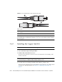
2.6.2
Installing the Copper Link Kit
2–18
Working With PCI Cards
3–1
3.1
Installing a PCI Card
3–1
3.2
Replacing a PCI Card
3–9
3.3
Installing Cables for PCI Cards
3–16
Servicing and Replacing Components
4–1
4.1
Service Procedures Task Map
4–2
4.2
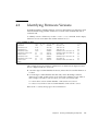
Identifying Firmware Versions
4.3
Replacing a Power Supply Unit
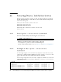
4.4
Powering Down a Link Before Service
4–3
4–4
4–6
4.4.1
The cfgadm -c disconnect Command
4.4.2
Example of the cfgadm -c disconnect Command
4.5
Preparing the Cable Plate for Service
4.6
Replacing a Carrier
4.7
Replacing a Link Cable
4.8
Replacing a Link Card in the Host Server
4.9
Replacing a Link Card in an I/O Boat
4.10
Installing a Second I/O Boat
4.11
Replacing an I/O Boat
4.12
4–6
4–6
4–7
4–9
4–13
4–13
4–14
4–16
4–19
4.11.1
Replacing a Boat in a Single Boat Configuration
4.11.2
Replacing a Boat in a Dual Boat Configuration
Replacing the External I/O Expansion Unit Chassis
4–19
4–21
4–24
4.12.1
Locating the New System Serial Number Label
4.12.2
Preparing the External I/O Expansion Unit
4–24
4–24
Contents
vii
4.13
4.12.3
Moving the Bezel to the New Chassis
4.12.4
Installing the External I/O Expansion Unit in the Rack
Powering Up a Link After Service
The cfgadm -c configure Command
4.13.2
Example of the cfgadm -c configure Command
4–33
4–34
A–1
A.1
Physical Specifications
A–2
A.2
Clearance for Service Access
A.3
Environmental Specifications
A–3
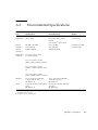
A.4
Power Source Requirements
A–4
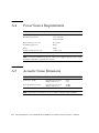
A.5
Acoustic Noise Emissions
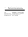
A.6
Agency Compliance Specifications
A–2
A–4
A–5
B. External I/O Expansion Unit LED Status Indicators
B.1
LED Locations
B.2
LED States
B–1
B–2
B–4
C. PCI Cards and Device Mapping
C.1
Device Mapping
C.2
Device Map Examples
C–1
C–1
C–3
C.2.1
Device Map for PCI Express Cards
C.2.2
Device Map for PCI-X Cards
C–3
C–4
Software Commands for the External I/O Expansion Unit
C.3.1
The ioxadm Command
C.3.2
The show-devs Command
C.3.3
The cfgadm Command
C.3.4
The prtdiag Command
D. Troubleshooting
viii
4–30
4–33
4.13.1
A. Specifications
C.3
4–26
C–6
C–7
C–8
C–11
C–12
D–1
External I/O Expansion Unit for SPARC Enterprise Mx000 Servers Installation and Service Manual • April 2011
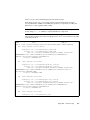
D.1
Using Hardware Symptoms to Troubleshoot Problems
D.2
Using Manual Techniques of Fault Isolation to Diagnose Error Messages
D–4
D.2.1
Error Messages and Fault Managed Resource Identifiers
D.2.2
I2C Failures
D–4
D–6
D.2.2.1
I2C Fault Isolated to a Single FRU
D.2.2.2
I2C Fault Spanning Multiple FRUs
D.2.2.3
I2C Fault When Accessing the Link Card Installed in the
Host D–11
D.2.3
Management Bus Failures
D.2.4
Cable Removed or Power Loss
D.2.5
Interrupt Signal Failures
D.2.6
FRU Discovery Failures
D.2.7
Index
D–2
D–7
D–7
D–12
D–13
D–14
D–15
D.2.6.1
Signal Failure
D–15
D.2.6.2
Boat Not Monitored
D.2.6.3
Link Card Mode Failure
D.2.6.4
Boat Location Failure
D–16
D–17
D–17
Reported Failures on the Microcontroller
D.2.7.1
Fan Controller Reset
D.2.7.2
Fan Controller Timeout
D–20
D.2.7.3
Bridge Controller Reset
D–20
D.2.7.4
Bridge Controller Timeout
D–19
D–19
D–21
Index–1
Contents
ix
x
External I/O Expansion Unit for SPARC Enterprise Mx000 Servers Installation and Service Manual • April 2011
Preface
This manual provides installation and service procedures for the External I/O
Expansion Unit from Oracle and Fujitsu.
This document is written for technicians, system administrators, authorized service
providers, and users who have advanced experience troubleshooting and replacing
hardware.
This chapter includes the following sections:
■
“External I/O Expansion Unit Documents” on page xi
■
“Text Conventions” on page xii
■
“Notes on Safety” on page xiii
■
“Documentation Feedback” on page xiii
External I/O Expansion Unit Documents
All documents for your External I/O Expansion Unit are available online at the
following locations:
■
Oracle documents:
http://download.oracle.com/docs/cd/E19322-01/index.html
■
Fujitsu documents:
http://www.fujitsu.com/sparcenterprise/manual/
■
Sun Oracle software-related manuals (Oracle Solaris OS, and so on):
http://www.oracle.com/technetwork/documentation/index.html
xi
External I/O Expansion Unit Documents
External I/O Expansion Unit Installation and Service Manual
External I/O Expansion Unit Product Notes
External I/O Expansion Unit Safety and Compliance Guide
Text Conventions
This manual uses the following fonts and symbols to express specific types of
information.
xii
Fonts/symbols
Meaning
Example
AaBbCc123
What you type, when contrasted
with on-screen computer output.
This font represents the example of
command input in the frame.
XSCF> adduser jsmith
AaBbCc123
The names of commands, files, and
directories; on-screen computer
output.
This font represents the example of
command input in the frame.
XSCF> showuser -P
User Name:
jsmith
Privileges:
useradm
auditadm
Italic
Indicates the name of a reference
manual
See the SPARC Enterprise
M3000/M4000/M5000/M8000/M90
00 Servers XSCF User’s Guide.
""
Indicates names of chapters,
sections, items, buttons, or menus
See Chapter 2, "System Features."
External I/O Expansion Unit for SPARC Enterprise Mx000 Servers Installation and Service Manual • April 2011
Notes on Safety
Read the following documents thoroughly before using or handling any External I/O
Expansion Unit.
■
External I/O Expansion Unit Safety and Compliance Guide.
■
SPARC Enterprise M3000/M4000/M5000/M8000/M9000 Servers Important Legal and
Safety Information
Documentation Feedback
If you have any comments or requests regarding this document, go to the following
web sites.
■
For Oracle users:
http://www.oraclesurveys.com/se.ashx?s=25113745587BE578
■
For Fujitsu users:
http://www.fujitsu.com/global/contact/computing/sparce_index.html
Preface
xiii
xiv
External I/O Expansion Unit for SPARC Enterprise Mx000 Servers Installation and Service Manual • April 2011
CHAPTER
1
Overview
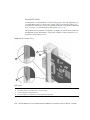
The External I/O Expansion Unit provides a host server with additional slots for PCI
cards.
■
The single I/O boat configuration provides six slots for I/O cards.
■
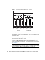
The optional two I/O boat configuration (FIGURE 1-1) provides twelve slots.
This chapter contains the following topics:
■
Section 1.1, “General Description” on page 1-2
■
Section 1.2, “Card Slots” on page 1-9
■
Section 1.3, “Carriers” on page 1-17
■
Section 1.4, “External I/O Expansion Unit Configurations” on page 1-34
■
Section 1.5, “LEDs” on page 1-36
■
Section 1.6, “System Management” on page 1-38
■
Section 1.7, “Site Preparation” on page 1-39
■
Section 1.8, “Service Information” on page 1-41
■
Section 1.9, “Electrostatic Discharge Precautions” on page 1-43
1-1
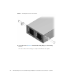
FIGURE 1-1
External I/O Expansion Unit, Front and Rear Views
1
2
Figure Legend
1.1
1
Front view
2
Rear view
General Description
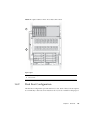
FIGURE 1-2 shows the major units for the External I/O Expansion Unit, which are
described separately in this chapter.
Note – All slot numbers run from left to right, regardless of whether you are
viewing the front or the back of the External I/O Expansion Unit. At the front of the
External I/O Expansion Unit, the power supplies are numbered from left to right.
I/O boats at the rear of the External I/O Expansion Unit are also numbered from left
to right.
1-2
External I/O Expansion Unit for SPARC Enterprise Mx000 Servers Installation and Service Manual • April 2011
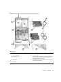
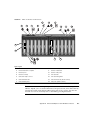
FIGURE 1-2
Major Units for the External I/O Expansion Unit, Top View
1
2
3
4
9a
6
5
9b
7
8b
8a
Figure Legend
1
Chassis
6
I/O boat 1
2
Power Supply Unit 1
7
Internal AC cable
3
Power Supply Unit 0
8
Cable management unit (One of two types is included. Type
8a routes cables to both sides of a rack. Type 8b routes
cables only the right side of a rack.)
4
Centerplane
9
Link kit (One of two types is included. 9a is the copper link
kit. 9b is the optical link kit.)
5
I/O boat 0
Chapter 1
Overview
1-3
1.1.1
Chassis
The External I/O Expansion Unit chassis includes the centerplane (item 4 in
FIGURE 1-2) and two non-removable internal AC cables (item 7 in FIGURE 1-2).
There are no serviceable components inside the chassis. If the centerplane or the
internal AC cables are damaged, the chassis must be replaced.
Note – A replacement chassis does not include power supply units (PSUs) or I/O
boats. Transfer the PSUs and I/O boats from the damaged chassis to the replacement
chassis.
Each internal AC cable supplies only one PSU. To ensure redundant power, use the
two AC cords supplied with the External I/O Expansion Unit to connect the internal
AC cables to separate AC sources.
Caution – Do not connect the internal AC cables directly to a power strip. Use the
the AC power cords supplied with the External I/O Expansion Unit to connect the
internal AC cables to electrical power.
Caution – Do not substitute other AC power cords for the AC power cords supplied
with the External I/O Expansion Unit. The substitute AC power cords might not
have the same power rating.
1-4
External I/O Expansion Unit for SPARC Enterprise Mx000 Servers Installation and Service Manual • April 2011
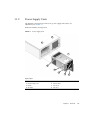
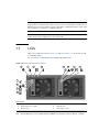
1.1.2
Power Supply Units
The External I/O Expansion Unit has two power supply units (PSUs) for
redundancy. See FIGURE 1-3.
Each PSU includes an integral fan.
FIGURE 1-3
Power Supply Unit
8
7
1
6
5
4
3
2
Figure Legend
1
PSU
5
Fan
2
Handle locking screw
6
Caution labels
3
Handle
7
PSU slot 0
4
AC switch
8
PSU slot 1
Chapter 1
Overview
1-5
1.1.2.1
AC Power
The PSU slots are powered through internal AC cables that extend out of the rear of
the chassis (item 7 in FIGURE 1-2).
The PSUs do not share AC current. Connect both internal AC cables to AC power.
The internal AC cable for a PSU is the cable terminating nearest that PSU slot.
The PSUs should be connected to two independent external AC power sources so
that service will not be interrupted if one AC power source fails.
1.1.2.2
Fans
A fan is located in the front of each PSU. If one fan fails, the remaining fan supplies
enough air to cool two I/O boats.
Note – The fan might turn on when you insert a PSU into the External I/O
Expansion Unit. This is normal behavior if you are installing a second PSU while the
first PSU is powered on. The fan receives DC power through the centerplane.
1-6
External I/O Expansion Unit for SPARC Enterprise Mx000 Servers Installation and Service Manual • April 2011
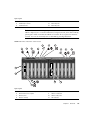
1.1.3
I/O Boats
The External I/O Expansion Unit can contain up to two I/O boats (FIGURE 1-4).
FIGURE 1-4
I/O Boat
5
1
6
2
3
7
4
Figure Legend
1
I/O boat
5
Boat slot 0
2
Captive screws
6
Boat slot 1
3
Link card carrier (slot 0)
7
Caution labels
4
PCI card carriers (slots 1-6)
There are two types of I/O boat, PCI-X and PCI Express. PCI cards are not
interchangeable between the two types of boats.
■
The PCI-X I/O boat accepts PCI-X cards and some older types of PCI cards.
■
The PCI Express I/O boat accepts PCI Express cards up to x8 lanes wide. PCI
Express x16 cards do not fit in this boat.
Chapter 1
Overview
1-7
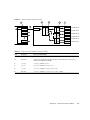
PCI-X and PCI Express I/O Boat Layouts, Compared
PCIPCI-E
Express
I/O boat
I/O boat
PCI-X I/O boat
Slot 6
Slot 5
32 lane
switch
Slot 4
Slot 2
Slot 1
Slot 5
6 PCI-X slots
32 lane
switch
Link 0
Bridge
Slot 6
Bridge
Slot 4
Slot 2
Slot 1
Link 0
Bridge
32 lane switch
Slot 3
32 lane switch
Slot 3
FIGURE 1-5
6 PCI
Express
6 PCI-E
slots slots
A PCI-X I/O boat is shown on the left side of FIGURE 1-5. This boat has six PCI-X
sockets and one link socket.
A PCI Express I/O boat is shown on the right side. There are six PCI Express sockets
and one link socket.
All PCI card data passes through the link card in the I/O boat.
A boat slot accepts either type of I/O boat.
When you run system diagnostics, the switches and bridges are displayed in the
output of OpenBoot PROM probing. However, the link cards themselves never
appear during OpenBoot PROM probing. For examples of OpenBoot PROM output,
see Appendix C.
Note – A bridge is a device that converts PCI Express and PCI-X signal formats and
connects multiple busses to a single bus. A switch is a device that connects multiple
busses to a single bus, without converting the signals to another format.
1-8
External I/O Expansion Unit for SPARC Enterprise Mx000 Servers Installation and Service Manual • April 2011
1.2
Card Slots
The card slots have the following characteristics:
■
An I/O boat has seven card slots. Slot numbers 0 through 6 are counted from left
to right.
■
Slot 0 is reserved for the link card. Slot 0 is the first slot in the left side of the I/O
boat. For information about link cards, see Section 1.2.2, “Link Kits” on page 1-12.
■
Slots 1-6 are for PCI cards. (PCI cards are sometimes known as host adapters or
host bus adapters.)
■
PCI card slots are hot-pluggable.
■
PCI-X and PCI Express sockets (FIGURE 1-5) are incompatible in length and height.
Installing a PCI-X or PCI Express card in the wrong type of I/O boat will damage
the card and the connector in the carrier slot.
■
The PCI Express I/O boat supports up to x8 card sockets. PCI Express x16 cards
are not supported in the PCI Express I/O boat.
Note – Graphics cards are not supported.
Caution – Do not insert a x16 PCI Express card in an I/O boat. The x16 card
connector is too large for the x8 card socket and will damage the socket.
1.2.1
Carriers
All PCI cards in the External I/O Expansion Unit are mounted on carriers
(FIGURE 1-25). Carriers control RFI emissions and maintain the proper flow of air
through the External I/O Expansion Unit.
The front of each carrier is labelled with its slot number (PCIX 1 or PCIE 1, and so
forth).
Note – Slot 0 is reserved for the link card. This slot is marked LINK 0.
There is only one type of carrier design used in the External I/O Expansion Unit. The
same carrier fits all slots in both types of PCI-X and PCI Express boats. Carriers are
physically keyed to fit only specific slot numbers. The keys can be adjusted for other
slots as needed.
Chapter 1
Overview
1-9
Caution – If you install a PCI card when the External I/O Expansion Unit is
running, be prepared to complete the installation within two minutes or so. If you
leave a carrier slot empty, the External I/O Expansion Unit might overheat.
New carriers include dummy cards. The dummy cards help the carriers to stay in
place and to control the passage of air through the I/O boat. For information about
dummy cards, see Section 1.2.1.2, “Dummy Cards” on page 1-11.
1.2.1.1
Carrier Slots
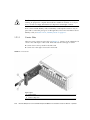
There are seven carriers in each I/O boat (FIGURE 1-6). Carriers can be adjusted to fit
various sizes and shapes of PCI cards. Link cards use the same type of carrier.
FIGURE 1-6
■
Carrier slot 0 is always used for the link card.
■
Carrier slots 1 through 6 are used for PCI cards.
PCI Carrier
Figure Legend
1-10
1
Carrier handle
2
Carrier locking screw
External I/O Expansion Unit for SPARC Enterprise Mx000 Servers Installation and Service Manual • April 2011
1.2.1.2
Dummy Cards
New carriers are shipped with dummy cards (FIGURE 1-7).
There are two types of dummy card, PCI-X and PCI Express. (The PCI Express card
might be labelled “PCI-E”.) Note that there are differences in their edge connectors.
FIGURE 1-7
Dummy Cards
PCI-E
PCI-X
Figure Legend
1
PCI Express version
2
PCI-X version
Note – Be certain that the dummy cards are fully seated. This action minimizes the
vibration of unused carriers in the I/O boat slots.
The service labels (not shown in FIGURE 1-7) on the dummy cards include simplified
instructions for removing and installing PCI cards.
Chapter 1
Overview
1-11
Caution – The two types of dummy cards are not interchangeable. If you replace a
PCI card with a dummy card, be sure that you use the right type of dummy card. The
differences in edge connectors on the dummy cards (FIGURE 1-7) are enough to
damage the PCI card socket on the I/O boat.
1.2.2
Link Kits
One link kit is required for each I/O boat.
A link kit includes two link cards. One link card goes into the host server. The other
link card goes into the I/O boat. The link cards are physically identical.
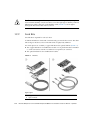
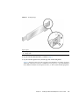
Two link options are available, a copper link kit and an optical link kit (FIGURE 1-8).
■
The copper link kit has one bidirectional cable. A low-profile bracket is included
so a link card can be used in a host that has low-profile I/O card slots.
■
The optical link kit has two unidirectional cables.
FIGURE 1-8
Link Kits
Figure Legend
1-12
1
Copper link kit
2
Optical link kit
External I/O Expansion Unit for SPARC Enterprise Mx000 Servers Installation and Service Manual • April 2011
Slot 0 in each I/O boat is the dedicated link card slot. Use slot 0 only for the link
card.
1.2.3
Cable Management
A cable management unit attaches to the rear of the system rack. There are two types
of cable management units.
■
Some racks allow the routing of cables along both sides of the rack. The type A
cable plate (FIGURE 1-9) supports cable routing along both the left and right sides
of the rack.
■
Some racks allow routing of cables only along the right side of the rack. The type
B cable plate (FIGURE 1-10) is optimized for cable routing along the right side of the
rack.
Chapter 1
Overview
1-13
Cable Management Unit (Type A) for Routing Cables to Both Sides of the
Rack
FIGURE 1-9
3
2
1
3
2
Figure Legend
1-14
1
Type A cable plate
2
Support brackets
3
Cable plate locking screws
External I/O Expansion Unit for SPARC Enterprise Mx000 Servers Installation and Service Manual • April 2011
FIGURE 1-10
Cable Management Unit (Type B) for Routing Cables Only to the Right Side of
a Rack
3
2
1
3
2
Figure Legend
1
Type B cable plate
2
Support brackets
3
Cable plate locking screws
Note – If the PSU1 power cable does not reach the rack power distribution unit,
route the cable on the left side of the rack.
1.2.3.1
Minimum Bend Radius for Link Cables
The link cables might be damaged if they are coiled too tightly.
■
The minimum bend radius for the copper link cable is 1.85 in./47 mm.
■
The minimum bend radius for optical link cables is 1.8 in./46 mm.
Chapter 1
Overview
1-15
Caution – Coiling the link cables with a smaller bend radius than listed above will
break the cables.
1.2.3.2
Cable Management Unit
The cable management unit contains two support brackets and a cable plate.
The support brackets attach with screws to the rear of the system rack. The cable
plate rests on the support brackets.
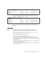
The cable plate has two positions (FIGURE 1-11).
■
In the normal position, the cable plate rests on the support brackets.
■
In the raised position, the cable plate rests slightly above the support brackets.
This position provides clearance for you to remove and replace an I/O boat.
FIGURE 1-11
Cable Plate (Side Views of Normal and Service Positions)
2
1
3
Figure Legend
1.3
1
Cable plate in the normal position (lowered)
2
Cable plate in the service position (raised)
3
Cable plate locking screw
Carriers
In the I/O boat, all PCI cards are mounted on carriers. When you insert the carrier
and card into the boat and push the carrier handle into the closed position, the
carrier mechanism automatically seats the PCI card.
FIGURE 1-12 shows a carrier with an attached PCI card.
1-16
External I/O Expansion Unit for SPARC Enterprise Mx000 Servers Installation and Service Manual • April 2011
Note – The service life of a carrier is at least 100 PCI card insertions. To avoid
premature failure of the carrier, do not repeatedly open and close the carrier more
than is necessary to familiarize yourself with its operation.
FIGURE 1-12
Carrier
1
2
3
Figure Legend
1
PCI card
2
Carrier
3
Carrier handle in unlocked position
FIGURE 1-13 shows the details of a typical carrier.
Chapter 1
Overview
1-17
FIGURE 1-13
Carrier Features
1
2
5
3
6
5
4
5
Figure Legend
1
Carrier main body (metal)
4
Carrier handle
2
Carrier plate (plastic)
5
Card locks (see Section 1.3.2, “Card Locks” on page 1-20)
3
Carrier slot keyholes
6
Turnaround area for card lock
1.3.1
Carrier Removal and Insertion
A carrier operates by raising or lowering a PCI card into or out of a card socket. The
vertical movement is approximately 0.4 in./10 mm.
A small metal latch (item 3 in FIGURE 1-14) is located at the front of the carrier. The
latch locks the carrier handle in the extended position. This action prevents the
carrier plate and PCI card from falling and damaging the PCI slot connector as you
pull the carrier unit out of the carrier slot.
1-18
External I/O Expansion Unit for SPARC Enterprise Mx000 Servers Installation and Service Manual • April 2011
After the carrier is out of the I/O boat, you can unlock the carrier handle by pushing
in the metal latch while pushing the carrier handle into its closed position. Note that
the closed position provides more vertical clearance for a PCI card when you install
or remove the PCI card.
When you insert the carrier into the I/O boat, the latch automatically unlocks itself.
FIGURE 1-14
Carriers
Figure Legend
1
Pull carrier handle to raise PCI card out of PCI slot socket
2
Push carrier handle and latch (3) to lower PCI card into socket
3
Latch
Caution – All carriers must contain either a PCI card or a dummy card to avoid loss
of cooling air.
Chapter 1
Overview
1-19
1.3.2
Card Locks
A PCI card is attached to the carrier with screw-mounted locks or retainers
(FIGURE 1-15). Card locks hold a PCI card to its carrier and prevent the PCI card from
shifting or tilting. The PCI card must be securely mounted in order for the carrier to
correctly seat the PCI card in the card socket in the I/O boat.
FIGURE 1-15
Card Locks
1
2
3
Figure Legend
1
Type A (Square). There are three of these.
2
Type B (S-shaped)
3
Type C (Small)
There are three types of locks:
1-20
■
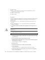
Type A is a square-shaped lock. Three of these are supplied with each carrier.
■
Type B is an oblong lock that has an S-shaped profile. It provides a longer
extension (0.75 in./19 mm) than type A. Type B can be used as a top or side
mount, wherever a longer reach is needed. One of this type is included with each
carrier.
External I/O Expansion Unit for SPARC Enterprise Mx000 Servers Installation and Service Manual • April 2011
■
Type C is a small quarter-round lock. It can support the bottom edge of a wide PCI
card, but only when the lock is at the far right side of its slot (the side farthest
from the front of the carrier). For a narrow width card, use this lock only to
support the side of the card. Do not use this lock to support the bottom edge of a
narrow width card because the lock might interfere with the card socket in the I/O
boat. This lock fits only the bottom slot on the carrier. One of this type is supplied
with each carrier.
One function of the locks is to secure the PCI card to the carrier. Another is to apply
a downward force to the top of the card to seat the card in the card socket when the
carrier is inserted into the I/O boat. In addition, the locks help prevent the card from
tilting so that card edge pins line up properly with the pins in the socket.
Because PCI card types are available in various sizes and shapes, you should choose
a combination of card locks that is best suited to the size and shape of the PCI card.
1.3.3
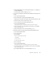
Tightening Sequence for Card Locks
To fasten a PCI card to a carrier so that the card will seat reliably, tighten the card
locks in the sequence shown in FIGURE 1-16 or FIGURE 1-17.
PCI card shapes and sizes can vary, so use the following instructions as suggestions,
not as strict requirements.
■
If the PCI card is wide, use the tightening sequence shown in FIGURE 1-16. A wide
card is one that can rest on the type C card lock (item 1 in FIGURE 1-16) when the
card lock is in its extreme right position.
■
If the PCI card is narrow, use the tightening sequence shown in FIGURE 1-17. A
narrow card is one that is too short to rest on the type C card lock when the card
lock is in its extreme right position.
Caution – If you move the type C card lock out of the extreme right position while
the plastic part of the card lock is facing down, the PCI card will not seat properly,
and the bottom of the card lock can damage the PCI card socket in the I/O boat. If
you move the type C card lock to the left at any time, always rotate the card lock so
that the plastic part faces either left or right.
Chapter 1
Overview
1-21
1.3.3.1
Tightening Sequence for Wide Cards
FIGURE 1-16
Card Lock Sequence for Wide Cards
2
3
4
1
●
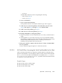
1.3.3.2
Rest the bottom edge of the PCI card on the type C card lock (number 1 in
FIGURE 1-16) to ensure that the bottom of the PCI card is perfectly horizontal,
then tighten the remaining card locks in the sequence shown.
Tightening Sequence for Narrow Cards
FIGURE 1-17
Card Lock Sequence for Narrow Cards
1
4
2
3
●
1-22
Tighten the upper left card lock (number 1 in FIGURE 1-17), while ensuring that
the card is perfectly horizontal. Then tighten the remaining card locks in the
sequence shown, as applicable.
External I/O Expansion Unit for SPARC Enterprise Mx000 Servers Installation and Service Manual • April 2011
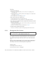
1.3.4
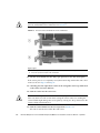
Examples of PCI Card Installation
FIGURE 1-15 shows the locks for a typical PCI card.
However, cards can be much wider or narrower, or taller or shorter. FIGURE 1-18,
FIGURE 1-19, and FIGURE 1-20 show how cards can vary in height, width, and shape.
Note – The lock arrangements shown in these figures are suggestions and are not
intended as requirements.
When installing a card, it might be necessary to swap locks from slot to slot in order
to find the best way to secure a PCI card to its carrier. Use TABLE 1-1 to select locks
that are best suited to your PCI card.
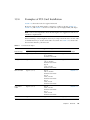
TABLE 1-1
Card and Lock Styles
Suggested Lock Type
PCI Card Shape
Top Lock/Card Height
Side Lock/Card Width
Bottom Lock
Example
C*
FIGURE 1-18
FIGURE 1-18
Wide
Type A (x2)
Type A
12 in./304 mm
maximum card width
Type
Average width
Type A (x2)
Type A
5.75 in./146 mm
minimum card width
Type B
5.0 in./127 mm
minimum card width
Type C†
Narrow width
Type A (1 or 2)
Type A
5.75 in./146 mm
minimum card width
Type B
5.0 in./127 mm
minimum card width
Type C
3.0 in./76 mm
minimum card width
FIGURE 1-18
Very narrow
width
Type A (1 or 2)
Type B
5.0 in./127 mm
minimum card width
Type C
3.0 in./76 mm
minimum card width
FIGURE 1-18
Tall
Type A
Type A or B
Type C‡
Chapter 1
FIGURE 1-18
Overview
1-23
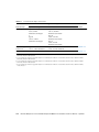
TABLE 1-1
Card and Lock Styles (Continued)
Suggested Lock Type
PCI Card Shape
Top Lock/Card Height
Side Lock/Card Width
Bottom Lock
Low height
Type A
2.0 in./51mm
minimum card height
or
Type B
1.25 in./31mm
minimum card height
Type A
5.75 in./146 mm
minimum card width
Type B
5.0 in./127 mm
minimum card width
Type C
3.0 in./76 mm
minimum card width
FIGURE 1-19
Very low height
and narrow
Type B
1.25 in./31mm minimum
Type C
3.0 in./76 mm minimum
FIGURE 1-20
Irregular shape
As needed
As needed
As needed**
Example
FIGURE 1-20
* Do not use the type C lock to support the bottom of a card if the lock will be in a location that causes the lock to interfere with the
PCI card connector in the I/O boat.
† Do not use the type C lock to support the bottom of a card if the lock will be in a location that causes the lock to interfere with the
PCI card connector in the I/O boat.
‡ Do not use the type C lock to support the bottom of a card if the lock will be in a location that causes the lock to interfere with the
PCI card connector in the I/O boat.
** Do not use the type C lock to support the bottom of a card if the lock will be in a location that causes the lock to interfere with the
card connector.
1-24
External I/O Expansion Unit for SPARC Enterprise Mx000 Servers Installation and Service Manual • April 2011
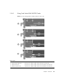
1.3.4.1
Using Card Locks With Tall PCI Cards
FIGURE 1-18
Lock Arrangements for Wide and Narrow PCI cards
1
2
3
4
Figure Legend
1
Tall and wide card
2 type A on top, 1 type A on right, 1 type C on bottom of the PCI card
2
Tall and average width card
2 type A on top, 1 type A on right, 1 type C on bottom of the PCI card
3
Tall and narrow card
1 type A on top, 1 type A on right, 1 type C on lower right side of the PCI card
4
Tall and very narrow card
1 type A on top, 1 type B on right, 1 type C on lower right side of the PCI card
Chapter 1
Overview
1-25
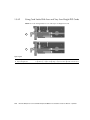
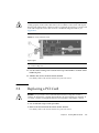
1.3.4.2
Using Card Locks With Low and Very Low Height PCI Cards
FIGURE 1-19
Lock Arrangements for Low and Very Low Height PCI cards
1
2
Figure Legend
1
Low height card
2 type A on top, 1 type A on right side, 1 type C on lower right side of the PCI card
2
Very low height card
1 type B on top, 1 type A on right edge, 1 type C on lower right side of the PCI card
1-26
External I/O Expansion Unit for SPARC Enterprise Mx000 Servers Installation and Service Manual • April 2011
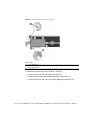
1.3.4.3
Using Card Locks With Unusual PCI Card Shapes
FIGURE 1-20
Lock Arrangements for Unusually-Shaped Cards
1
2
Figure Legend
1
Very low height and narrow width card
1 type B on top, 1 type C on right side of the PCI card
2
Irregularly-shaped card
1 type A and 1 type B on top, 1 type A on right side, 1 type C on lower right
side of the PCI card
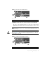
1.3.5
PCI Card Mounting Problems
1.3.5.1
Tilted Cards
There are two common problems that involve PCI cards that turn at an angle when
mounted in PCI carriers.
■
The most common problem is that a PCI card can slip and tilt during seating when
you do not apply enough pressure on a PCI carrier card lock when mounting the
card on the carrier.
■
A less common problem is that the bracket of a PCI card will bend when you
apply too much pressure on a PCI carrier card lock when mounting the card on a
carrier.
Chapter 1
Overview
1-27
FIGURE 1-21
Excessive Force on a Lock Can Bend or Break the PCI Card
Figure Legend
1
Correct
2
Incorrect
Here are some rules to avoid the tilting of PCI cards:
1. You must have at least one lock on top of the card. If the top of the card is too low
to accept a lock, the card cannot be used.
2. Find a lock to fit the top of the card and provide side support to prevent the card
from tilting. A tilted card (FIGURE 1-21) will not seat properly.
3. Support of the bottom of the card is not a major priority because the carrier plate
itself provides some support for the bottom of the card.
4. Use only enough pressure to hold the lock against the PCI card. The bottom of the
PCI card should stay parallel with the bottom of the carrier.
1-28
External I/O Expansion Unit for SPARC Enterprise Mx000 Servers Installation and Service Manual • April 2011
1.3.5.2
Hidden Problems
The following features are located inside the front housing of the carrier. Because
they are difficult to see, they can complicate the mounting of cards on carriers.
■
Card alignment post (FIGURE 1-22 and FIGURE 1-23)
■
Card alignment tab (FIGURE 1-22)
■
Internal RFI gasket (FIGURE 1-24)
Alignment Post and Alignment Tab
The card alignment post and the card alignment tab help to keep the front of the PCI
card in the correct vertical orientation, with support from properly-installed card
locks.
FIGURE 1-22
Card Alignment Post and Card Alignment Tab
1
2
Figure Legend
1
Card alignment post
2
Card alignment tab
Chapter 1
Overview
1-29
The post fits in a notch in the metal bracket of the PCI card (item 1 in FIGURE 1-22). If
you do not position the post in the notch, the card mounting bracket might bend, so
that the card lies at an angle on the carrier. The angle prevents the card from making
proper electrical contact with the socket in the I/O boat.
The tab (item 2 in FIGURE 1-22) fits in a notch at the bottom of the PCI card. The tab
helps to align the card when you install it in the carrier. (Note that some card types
might not have the notch).
Note – The tab lifts the front of the card out of the card connector when you remove
the carrier from the I/O boat. If you cannot use a type C lock (FIGURE 1-15) to support
the bottom of the PCI card, the card alignment tab is the only point that can provide
support to lift the card out of the socket.
FIGURE 1-23 shows how the bracket fits over the card alignment post.
1-30
External I/O Expansion Unit for SPARC Enterprise Mx000 Servers Installation and Service Manual • April 2011
FIGURE 1-23
Card Alignment Post (Detail)
1
3
2
Figure Legend
1
Carrier front housing
2
Card alignment post
3
PCI card bracket
Chapter 1
Overview
1-31
Internal RFI Gasket
An RFI gasket is located inside the carrier housing, next to the card alignment post.
(A smaller RFI gasket is located on the outside of the carrier housing.) When you
insert the PCI card into the carrier, be sure that the bottom of the metal card bracket
does not scrape or loosen the bottom of the gasket (FIGURE 1-24).
The gasket material is flexible enough that you might not notice that the bracket has
dislodged the gasket. Remember to inspect the condition of this gasket before you
install the carrier in the I/O boat.
FIGURE 1-24
Internal RFI Gasket
1
2
3
4
Figure Legend
1
PCI card
2
RFI gasket (extends to the bottom front of the PCI carrier)
3
Correct example: the RFI gasket lies flat
4
Incorrect example: the card bracket has hooked behind the RFI gasket
1-32
External I/O Expansion Unit for SPARC Enterprise Mx000 Servers Installation and Service Manual • April 2011
1.3.6
Carrier Keys
Each carrier is keyed to a specific slot (FIGURE 1-25) in the I/O boat. The key is an M2
screw on the top of each carrier. Each carrier slot (0 through 6) will accept only a
carrier that has a key in the hole location for that slot.
FIGURE 1-25
Screw Hole Locations for the Carrier Slot Key
1
2
Figure Legend
1
Key (M2 screw)
2
Hole locations for carrier slots 0, 1, 2, 3 (front row)*
Hole locations for carrier slots 4, 5, 6, 7 (rear row)†
* Hole 0 and slot 0 are for the link card only.
† Hole 7 is reserved for future configurations.
If you replace a carrier, install the key in the keyhole that corresponds to the slot that
you use. A replacement carrier includes one key. It also includes an assortment of
labels. Affix the appropriate label (LINK 0, PCIE n, or PCIX n) to the front of the
replacement carrier for easy identification.
Chapter 1
Overview
1-33
1.4
External I/O Expansion Unit
Configurations
The External I/O Expansion Unit is available with one or two I/O boats. Two types
of link kits (copper and optical) are also available.
1.4.1
Single Boat Configuration
The base configuration for an External I/O Expansion Unit has a single boat, with a
filler panel in the second boat bay. FIGURE 1-26 shows a host server and a base
External I/O Expansion Unit in the same rack.
A link card in the host server connects to a link card in the External I/O Expansion
Unit. One or two link cables connect the two link cards. (The cables are not shown to
scale.)
The copper link kit includes a single 13 ft/4 m link cable.
The optical link kit includes two link cables. The link cables are either 33 ft/10 m or
80 ft/25 m cables. Note that in FIGURE 1-26, the link cables are crossed so that the
Transmit port (TX) of one link card connects to the Receive port (RX) of the other link
card.
1-34
External I/O Expansion Unit for SPARC Enterprise Mx000 Servers Installation and Service Manual • April 2011
FIGURE 1-26
Optical Cables Connect TX Sockets to RX Sockets
1
2
Figure Legend
1.4.2
1
External I/O Expansion Unit
2
Host server
Dual Boat Configuration
The dual boat configuration provides twelve I/O slots. Each of the I/O boats requires
its own link kit, so the host server must have two I/O slots available for this purpose.
Chapter 1
Overview
1-35
Note – If you are installing a second boat in the External I/O Expansion Unit, both
boats must be connected to the same host server. Do not connect the second boat to a
different server. The second boat can be connected to a different domain on the same
server, but not to a domain on a different server.
Note – Do not daisy-chain two boats (connect a boat to another boat through link
cards). Daisy-chain configurations are not allowed.
1.5
LEDs
LEDs are located on the front (FIGURE 1-27) and rear (FIGURE 1-28) of the chassis and
on individual PSUs.
See Appendix B for information about interpreting LED states.
FIGURE 1-27
LEDs on the Front of the Chassis
1
2
3
4
9
10
11
12
5
6
7
8
Figure Legend
1
Chassis locate (LED and switch)
7
PSU0 DC power
2
Chassis fault/service required
8
PSU0 AC power
3
Chassis power
9
PSU1 ready to remove
1-36
External I/O Expansion Unit for SPARC Enterprise Mx000 Servers Installation and Service Manual • April 2011
Figure Legend
4
Chassis overtemp
10
PSU1 fault/locate
5
PSU0 ready to remove
11
PSU1 DC power
6
PSU0 fault/locate
12
PSU1 AC power
Note – The Locate LED is a lighted push-button switch. When the flashing of its
LED has helped you to locate the External I/O Expansion Unit, turn off the LED by
pressing the switch. Note that the LED does not turn off if you press less than 0.5
seconds. You can also manually turn on the LED by pressing the button.
FIGURE 1-28
LEDs on the Rear of the Chassis
5
1
2
3
6
7
4
8
9
10
11
12
13
11
12
14
Figure Legend
1
Chassis locate (LED and switch)
8
I/O boat 1 ready to remove
2
3
Chassis fault/service required
9
I/O boat 1 fault/locate
Chassis power
10
4
I/O boat 1 DC power
Chassis overtemp
11
Link card data
Chapter 1
Overview
1-37
Figure Legend
5
I/O boat 0 ready to remove
12
Link card management
6
I/O boat 0 fault/locate
13
Slot attention/locate (all PCI carriers)
7
I/O boat 0 DC power
14
Slot power (all PCI carriers)
Note – On the optical link card, the LEDs for link card data and link card
management are located next to the optical cable sockets. Although the LEDs are
near the sockets, they do not have any direct relationship to the sockets and are not
intended to indicate the activity of the optical cable sockets.
1.6
System Management
The PSUs contain temperature sensors. The PSUs can shut down automatically if
they detect an extreme temperature. The PSUs also have sensors for voltage and
current levels.
Temperature sensors are also located inside the I/O boats. FRU ID circuits are located
on the link cards, the PSUs, the I/O boats, and on the chassis centerplane.
Temperature data and FRU ID information is available on an I2C bus (Inter-IC bus)
in the External I/O Expansion Unit and the link cards.
The service processor in the host system can monitor the I2C bus in the External I/O
Expansion Unit. The service processor can power down the External I/O Expansion
Unit if parameters exceed maximum limits.
There is no service processor in the External I/O Expansion Unit itself.
The ioxadm command is available on the host system to display External I/O
Expansion Unit sensor information and LED states. You can also use ioxadm to
control the Locate LEDs in the External I/O Expansion Unit and to power on or off
FRUs in the External I/O Expansion Unit. Refer to the ioxadm (8) man page for more
information.
For examples of software commands, see Appendix C.
1-38
External I/O Expansion Unit for SPARC Enterprise Mx000 Servers Installation and Service Manual • April 2011
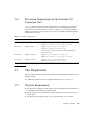
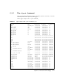
1.6.1
Maximum Temperatures in the External I/O
Expansion Unit
TABLE 1-1 summarizes the maximum temperatures for the External I/O Expansion
Unit. The table also includes error messages that the host might display if these
temperatures exceed the maximum values. Two types of error messages might be
displayed on the host console, Ereport (error report) and FMA (Fault Management
Architecture) messages.
TABLE 1-2
Maximum Temperatures
Temperature
Where Measured
Comments
38˚C (100˚F)
At the intake of the PSU
Ereport: ereport.chassis.env.temp.otw
FMA: fault.chassis.iox.env.temp.over-warn
54˚C (130˚F)
Inside the PSU
Ereport: ereport.chassis.env.temp.otf
FMA: fault.chassis.iox.power.fail
Note: The PSU can turn itself off if its internal temperature
exceeds this value.
60˚C (140˚F)
Inside the I/O boat
Ereport: ereport.chassis.env.temp.otw
FMA: fault.chassis.iox.env.temp.over-warn
65˚C (150˚F)
Inside the I/O boat
Ereport: ereport.chassis.env.temp.otf
FMA: fault.chassis.iox.power.fail
1.7
Site Preparation
The following information summarizes installation requirements for the External I/O
Expansion Unit.
For additional specifications and compliance information, see Appendix A.
1.7.1
Physical Requirements
■
The External I/O Expansion Unit with the cable management unit attached is 17.3
in./440 mm wide and 39.4 in./1000 mm deep.
■
The movement of air through the External I/O Expansion Unit chassis is from
front to back.
■
The External I/O Expansion Unit is four rack units tall (6.9 in./175 mm).
Chapter 1
Overview
1-39
■
Service access to the External I/O Expansion Unit is from the front or rear. The
mounting rails do not slide.
■
The choice of mounting location in a rack can be limited by the length of the link
cable:
■
■
The optical link kit includes either 33 ft/10 m or 80 ft/25 m cables. The External
I/O Expansion Unit can be located some distance from the host server rack.
■
The copper link kit includes a 13 ft/4 m cable.
The maximum weight of the External I/O Expansion Unit is approximately 81
pounds (36.8 kg).
Caution – Mount the heaviest subassemblies at the lowest available opening in a
rack to minimize the precarious effects of a top-heavy system.
Note – Do not install another product between two External I/O Expansion Units if
the product is short in height and shorter in depth than the External I/O Expansion
Units. If there is little space between the upper and lower External I/O Expansion
Units, there might not be enough space for your hands and arms to connect cables on
the rear of the product.
1.7.2
1-40
Electrical Requirements
■
The maximum wattage per PCI card is 25 watts.
■
Two AC cords (supplied) must be used with the internal AC cables (FIGURE 1-2).
■
The supply voltage is 100 VAC to 240 VAC, 50-60 Hz.
■
The maximum power rating of External I/O Expansion Unit is 600 watts.
External I/O Expansion Unit for SPARC Enterprise Mx000 Servers Installation and Service Manual • April 2011
1.8
Service Information
Service and installation information is also available on service labels that are located
on the External I/O Expansion Unit top cover and on the dummy cards that are
shipped with new carriers.
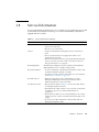
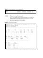
TABLE 1-3
Service Information Summary
Topic
Comments
Access
• Service access to the External I/O Expansion Unit is from the
front or rear of the unit.
• The top cover is removable.
Air flow
• Air flow in the External I/O Expansion Unit is from front to
back.
• Fans are located in the power supply units. There are no
separate fans or fan trays.
• The PSU and I/O boat slots have pivoting metal flaps that drop
down to close the slots when a PSU or I/O boat is removed.
This prevents the loss of cooling air.
Mounting brackets
The External I/O Expansion Unit is mounted on fixed brackets.
Sliding brackets are not available for this product.
PCI card installation
• To avoid overheating of the External I/O Expansion Unit, cards
should be installed as quickly as possible.
• To prepare yourself to install a card within one or two minutes,
see Section 1.3, “Carriers” on page 1-17.
PCI cable removal
• When removing cables such as LAN cables, if you have
difficulty unlatching the connector, press the latch with a
flathead screwdriver to remove the cable.
AC cables and cords
• The internal AC cables (FIGURE 1-2) are not removable. If they
are damaged, replace the chassis.
• Each internal AC cable connects to only one PSU. Connect both
AC cables to AC power to ensure that both PSUs are
operational.
• The internal AC cables are not connected directly to AC voltage.
Use the AC power cords to connect the internal AC cables to AC
voltage.
• Do not use AC cables designed for other products with the
External I/O Expansion Unit.
Chapter 1
Overview
1-41
TABLE 1-3
1-42
Service Information Summary (Continued)
Topic
Comments
Link cables
• The optical version of the link kit includes two unidirectional
cables. The ends of the cables are marked TX and RX (transmit
and receive, respectively).
• The copper link kit has one cable. The connector is designed in a
way such that it cannot be connected upside down.
Jumpers
• The External I/O Expansion Unit does not have jumper pins.
• For information about any jumper pins that might be present on
a specific PCI card, see the instructions that came with the card.
System serial number
• For a new system, the system serial number is located on labels
on the chassis bezel and inside the right I/O boat bay.
• For a FRU chassis, the system serial number is located inside the
left I/O boat bay. Two additional serial number labels are
included to be placed on the chassis bezel.
External I/O Expansion Unit for SPARC Enterprise Mx000 Servers Installation and Service Manual • April 2011
1.9
Electrostatic Discharge Precautions
Caution – Circuit board components are vulnerable to damage by electrostatic
discharge (ESD). An electrostatic charge can build up on the human body and then
discharge when you touch a board. Such discharge can be produced by walking
across a carpet and touching a board, or by other similar cause. Before handling any
board, ensure that you dissipate your body’s charge. Touch a conductive surface of
the chassis or other element connected to common earth ground to discharge the
static electricity present in your body.
To minimize risk of ESD damage:
■
Handle the board by the edges only.
■
Store the board in an antistatic bag.
■
Use a grounding strap and an ESD mat whenever you work on a board.
Chapter 1
Overview
1-43
1-44
External I/O Expansion Unit for SPARC Enterprise Mx000 Servers Installation and Service Manual • April 2011
CHAPTER
2
Installing the External I/O
Expansion Unit in a Rack
The following topics are in this chapter:
2.1
■
Section 2.1, “Tools” on page 2-1
■
Section 2.2, “Installing the Mounting Brackets in a Rack” on page 2-2
■
Section 2.3, “Installing the External I/O Expansion Unit in the Rack” on page 2-7
■
Section 2.4, “Installing the Cable Management Unit” on page 2-9
■
Section 2.5, “Installing the AC Cords” on page 2-13
■
Section 2.6, “Installing the Link Kit” on page 2-16
Tools
You need the following tools for this installation:
■
Phillips No. 1 screwdriver
■
Phillips No. 2 screwdriver
■
ESD-protected mat and a grounding strap
■
(Suggested) digital voltmeter to verify correct grounding
2-1
2.2
Installing the Mounting Brackets in a
Rack
The External I/O Expansion Unit can be installed in either an equipment rack or the
rack space in the SPARC Enterprise M8000 server.
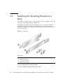
The External I/O Expansion Unit mounting kit (FIGURE 2-1) includes a right-side
mounting bracket and a left-side mounting bracket. The mounting brackets are
adjustable for length and are shipped unassembled. The mounting kit includes two
chassis lock brackets.
FIGURE 2-1
Mounting Kit
1
2
3
4
Figure Legend
1
Left mounting bracket
2
Right mounting bracket
3
Left chassis lock bracket
4
Right chassis lock bracket
1. Use an antistatic strap for this procedure.
2. Locate a suitable mounting location in the rack.
2-2
External I/O Expansion Unit for SPARC Enterprise Mx000 Servers Installation and Service Manual • April 2011
■
The External I/O Expansion Unit occupies a height of four rack units (6.9 in./175
mm).
■
Mount the heaviest subassemblies at the lowest available opening to minimize the
precarious effects of a top-heavy system.
■
If you are installing more than one External I/O Expansion Unit, install them
together. Do not install a shorter subassembly between External I/O Expansion
Unit where the rear of the shorter subassembly might difficult to reach.
■
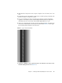
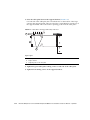
If the rack is marked with rack units, place the mounting bracket so that the lower
screw hole on the bracket is one hole above an RU mark (FIGURE 2-2). This aligns
the mounting bracket with the lower RU mark.
FIGURE 2-2
Typical Rack Unit Marks
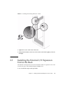
3. Using No. 2 Phillips screws, attach the chassis lock brackets to the sides of the
External I/O Expansion Unit (FIGURE 2-3).
Chapter 2
Installing the External I/O Expansion Unit in a Rack
2-3
FIGURE 2-3
Installing the Chassis Lock Brackets
4. Loosen the screws (FIGURE 2-4) that hold the sliding flanges to the mounting
brackets.
This action allows the rear flanges to adjust to fit different rack depths.
2-4
External I/O Expansion Unit for SPARC Enterprise Mx000 Servers Installation and Service Manual • April 2011
FIGURE 2-4
Sliding Flange
1
2
Figure Legend
1
Sliding flange
2
Flange crews
5. If your rack has threaded holes, continue at Step 7.
6. If your rack has square holes, install cage nuts in the rack pillars.
TABLE 2-1 lists the locations for the cage nuts. Note that these are relative locations.
Adjust the actual hole locations as needed to leave space for a power distribution
unit, additional External I/O Expansion Units, or other rack-mounted equipment.
Chapter 2
Installing the External I/O Expansion Unit in a Rack
2-5
TABLE 2-1
Cage Nut Locations
Rack Unit
Hole No.
4
12
Front
Rear
cage nut
cage nut
6
cage nut
cage nut
5
cage nut
cage nut
cage nut
cage nut
11
10
3
9
8
7
2
4
1
3
2
1
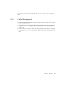
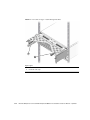
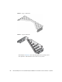
7. Attach the mounting brackets to the rack (FIGURE 2-5):
a. At the front of the rack, orient the hooked portion of the mounting bracket
away from you.
b. Loosely attach the front of the mounting bracket to the rack.
Install and tighten the screws, then loosen each screw approximately one-half
turn.
c. Repeat Step a and Step b for the second mounting bracket.
d. At the rear of the rack, slide the end of each mounting bracket to fit the depth
of the rack.
e. Loosely attach the rear ends of the mounting brackets to the rack.
f. Narrow the space between the rear ends of the mounting brackets by sliding
the ends of the brackets toward each other.
Note – At the front of the rack, the space between the brackets should be equal to or
slightly wider than the width of the External I/O Expansion Unit chassis. At the rear
of the rack, the space between the brackets should be slightly narrower than the
width of the External I/O Expansion Unit chassis. This arrangement allows the
correct fitting of the brackets to the sides of the External I/O Expansion Unit. See
Section 2.3, “Installing the External I/O Expansion Unit in the Rack” on page 2-7.
2-6
External I/O Expansion Unit for SPARC Enterprise Mx000 Servers Installation and Service Manual • April 2011
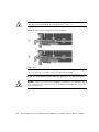
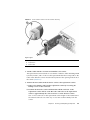
FIGURE 2-5
Installing the Mounting Brackets in a Rack
8. Tighten the screws at the front of the rack.
9. Verify that the brackets at the rear of the rack can still slide slightly to the left
and right.
2.3
Installing the External I/O Expansion
Unit in the Rack
The External I/O Expansion Unit can be installed in either an expansion rack or the
19-inch rack space in the SPARC Enterprise M8000 server.
1. Use an antistatic strap for this procedure.
Chapter 2
Installing the External I/O Expansion Unit in a Rack
2-7
2. Place the External I/O Expansion Unit on the front of the mounting brackets and
slide the External I/O Expansion Unit into the rack.
As you slide the External I/O Expansion Unit into the rack, the sides of the
External I/O Expansion Unit chassis push the ends of the brackets apart from each
other. When the chassis is almost completely in the rack, bulges on the underside
of the chassis contact hooks that are located on the mounting brackets, wedging
the mounting brackets tightly against the sides of the chassis. This wedging action
stabilizes the External I/O Expansion Unit and is necessary to reduce the amount
of vibration that occurs when the system is running.
3. Tighten the screws at the rear of the mounting brackets.
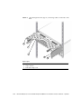
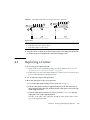
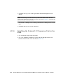
4. Lock the front of the External I/O Expansion Unit in place with two screws on
each side (FIGURE 2-6).
FIGURE 2-6
2-8
Installing the External I/O Expansion Unit in the Rack
External I/O Expansion Unit for SPARC Enterprise Mx000 Servers Installation and Service Manual • April 2011
2.4
Installing the Cable Management Unit
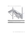
At the rear of the rack, install the cable management support brackets:
1. Use an antistatic strap for this procedure.
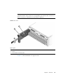
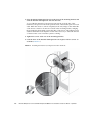
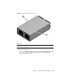
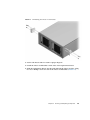
2. Place the support brackets just above the chassis mounting brackets (FIGURE 2-7)
and loosely attach the support brackets to the rack with two screws each.
Do not tighten the screws yet.
Note – The cable management unit includes one cable plate, either type A
(FIGURE 2-8) or type B (FIGURE 2-9).
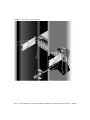
■
Use the type A cable plate in racks that allow the routing of cables along both
sides of the rack.
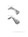
■
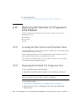
Use the type B cable plate in racks that allow the routing of cables only along the
right side of the rack.
Chapter 2
Installing the External I/O Expansion Unit in a Rack
2-9
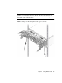
FIGURE 2-7
2-10
Installing the Support Brackets
External I/O Expansion Unit for SPARC Enterprise Mx000 Servers Installation and Service Manual • April 2011
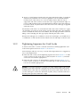
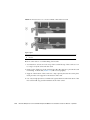
FIGURE 2-8
Type A Cable Plate
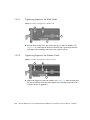
FIGURE 2-9
Type B Cable Plate
Chapter 2
Installing the External I/O Expansion Unit in a Rack
2-11
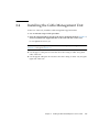
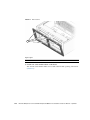
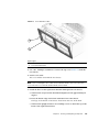
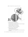
3. Place the cable plate between the support brackets (FIGURE 2-10).
On each side of the cable plate, the forward tab rests on the bottom of the large
cutout in the support bracket. The rear tab rests in a small depression in the top of
the support bracket. This is the normal operating position for the cable plate.
FIGURE 2-10
Cable Plate and Support Bracket, Side View
1
2
3
Figure Legend
1
Cable plate
2
Support bracket
3
Supporting tabs on the cable plate
4. Tighten the green cable plate locking screws at each side of the cable plate.
5. Tighten the mounting screws on the support brackets.
2-12
External I/O Expansion Unit for SPARC Enterprise Mx000 Servers Installation and Service Manual • April 2011
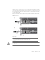
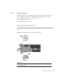
2.5
Installing the AC Cords
1. Use an antistatic strap for this procedure.
2. Attach an AC cord to an internal AC cable at the rear of the External I/O
Expansion Unit, then connect the AC cord to an AC outlet.
■
The PSUs should be connected to two independent external AC power sources so
that service will not be interrupted if one AC power source fails.
■
For the type A cable plate (FIGURE 2-8), route each AC cord along the nearest side
of the rack.
■
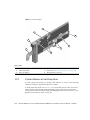
For the type B cable plate (FIGURE 2-9), route the left AC cord over the top of the
cable plate to the right side of the rack. Place the connector of the left AC internal
cable in the rectangular opening in the top of the type B cable plate to save space.
See FIGURE 2-12.
Note – If the PSU1 power cable does not reach the rack power distribution unit,
route the cable on left side of the rack.
Note – Do not connect the internal AC cable directly to an AC socket (power
distribution unit or power strip). You must use the AC cords supplied with the
External I/O Expansion Unit.
3. Attach an AC cord to the remaining internal AC cable as in Step 2.
Note – The fan might turn on when you insert a power supply into the External I/O
Expansion Unit. This is normal behavior if you are replacing a PSU while the other
PSU is powered up.
Chapter 2
Installing the External I/O Expansion Unit in a Rack
2-13
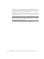
FIGURE 2-11
AC Cables for Type A Cable Management Plate
1
2
Figure Legend
2-14
1
Internal AC cable, left
2
Internal AC cable, right
External I/O Expansion Unit for SPARC Enterprise Mx000 Servers Installation and Service Manual • April 2011
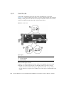
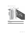
FIGURE 2-12
AC Cables and Cords for Type B Cable Management Plate
1
2
3
Figure Legend
1
Internal AC cable, left
2
AC cord (connectors are placed in rectangular opening to reduce height)
3
Internal AC cable, right
Chapter 2
Installing the External I/O Expansion Unit in a Rack
2-15
4. If you wish to test the External I/O Expansion Unit for basic electrical
functionality, do the following:
a. Turn on the PSU AC switches.
The switches are located on the front of the power supplies.
The LEDs on the power supplies should display the following indications after
a short initialization period.
TABLE 2-2
Normal PSU Indications
LED
Indication
AC Power
On (green LED)
DC Power
On (green LED)
For other LED combinations, see TABLE B-4.
b. Turn off the PSU AC switches.
The LEDs on the PSUs continue glowing until DC current in the PSUs is
depleted. This can take approximately five to ten seconds.
2.6
Installing the Link Kit
A link kit includes two identical link cards, one for the host server and one for the
I/O boat. You can install either card in either location.
The link card in the I/O boat is always installed in boat slot 0. If your External I/O
Expansion Unit has two I/O boats, then link cards must be located in slot 0 of both
boats.
Note – If you are installing a second boat in the External I/O Expansion Unit, both
boats must be connected to the same host server. Do not connect the second boat to a
different server. The second boat can be connected to a different domain on the same
server, but not to a domain on a different server.
Note – Do not daisy-chain two boats (connect a boat to another boat through link
cards). Daisy-chain configurations are not allowed.
Your link kit is one of two types:
2-16
External I/O Expansion Unit for SPARC Enterprise Mx000 Servers Installation and Service Manual • April 2011
2.6.1
■
Optical interface and two cables — see Section 2.6.1, “Installing the Optical Link
Kit” on page 2-17
■
Copper interface and one cable — see Section 2.6.2, “Installing the Copper Link
Kit” on page 2-18
Installing the Optical Link Kit
Note – The minimum bend radius for optical link cables is 1.8 in./46 mm.
1. Use an antistatic strap for this procedure.
2. Install a link card in the host server.
See the service manual for your host server for instructions for installing an PCI
card.
3. If a link card is not already installed in the I/O boat, install it now.
Slot 0 is used for the link card. It is the leftmost slot in the boat. For details about
card removal and replacement, see Section 3.1, “Installing a PCI Card” on
page 3-1.
Caution – The carrier can be damaged during removal and during insertion. For
safe handling of the carrier, read the cautions in Section 3.1, “Installing a PCI Card”
on page 3-1.
4. Install the link cables.
Note – The two optical link cables are identical. One end of a cable is marked TX.
The other end is marked RX (FIGURE 2-13). When you route the cables, ensure that the
TX plug of one cable is paired with the RX plug of the other cable.
a. At the I/O boat, connect a plug marked TX into the TX port on the link card.
Connect the RX plug of the second cable into the RX port.
b. At the host server, connect a plug marked TX to the TX port on the link card.
Connect the RX plug of the remaining cable into the RX port.
Chapter 2
Installing the External I/O Expansion Unit in a Rack
2-17
FIGURE 2-13
TX and RX Labels on the Optical Link Cable
1
2
Figure Legend
1
TX label
2
RX label
Note – Check the labels to verify that each plug is connected to the correct port. The
TX and RX plugs are identically shaped, so it is easy to incorrectly connect a plug to
the wrong port.
2.6.2
Installing the Copper Link Kit
Note – The minimum bend radius for the copper link cable is 1.85 in./47 mm.
1. Use an antistatic strap for this procedure.
2. Install a link card in the host server.
See the service manual for your host server for instructions for installing a PCI
card in a host slot.
Note – Low profile brackets that are included in some copper link kits are not used
for SPARC Enterprise M4000/M5000/M8000/M9000 servers.
3. If a link card is not already installed in the I/O boat, install it now.
Slot 0 is used for the link card. It is the leftmost slot in the boat. For details about
card removal and replacement, see Section 3.1, “Installing a PCI Card” on
page 3-1.
2-18
External I/O Expansion Unit for SPARC Enterprise Mx000 Servers Installation and Service Manual • April 2011
Caution – The carrier can be damaged during removal and during insertion. For
safe handling of the carrier, read the cautions in Section 3.1, “Installing a PCI Card”
on page 3-1.
4. Connect the link cable to both link cards.
FIGURE 2-14
Copper Link Cable Plug
Note – If it is necessary to disconnect a link cable, pull the ring-shaped tab
approximately 0.15 in./2 mm in the direction shown by the arrow in FIGURE 2-15.
Caution – Do not pull the ring tab more than 0.15 in./2 mm, or it will break. When
disconnecting the cable from a link card, pull the cable plug while pulling carefully
on the ring tab.
FIGURE 2-15
Copper Link Cable Ring Tab
Chapter 2
Installing the External I/O Expansion Unit in a Rack
2-19
2-20
External I/O Expansion Unit for SPARC Enterprise Mx000 Servers Installation and Service Manual • April 2011
CHAPTER
3
Working With PCI Cards
This chapter gives procedures for installing PCI and link cards, and related cables.
3.1
■
Section 3.1, “Installing a PCI Card” on page 3-1
■
Section 3.2, “Replacing a PCI Card” on page 3-9
■
Section 3.3, “Installing Cables for PCI Cards” on page 3-16
Installing a PCI Card
1. Determine which card locks you will use to mount your PCI card on a carrier.
The size and shape of the PCI card affect the quantity and type of card locks you
use. Before you start this procedure, you must decide which locks you will use for
the PCI card. See Section 1.3.2, “Card Locks” on page 1-20
Caution – If you install a PCI card when the External I/O Expansion Unit is
running, be prepared to complete the installation within two minutes or so. If you
leave a carrier slot empty, the External I/O Expansion Unit might overheat.
2. Use an antistatic strap for this procedure.
3. Unscrew the carrier locking screw (item 2 in FIGURE 3-1) on the carrier handle.
3-1
FIGURE 3-1
Unlocking and Removing a Carrier
Figure Legend
1
Carrier handle
2
Carrier locking screw
4. Press lightly on the front of the carrier, and pull out the carrier handle until it
clicks into the open position (approximately 1.5 in./38 mm).
Pressing the front of the carrier prevents movement of the carrier when you pull
the carrier handle.
Caution – Pulling the carrier handle raises the carrier plate. If the carrier moves
forward before the carrier plate is completely raised, the plastic locator bar
(FIGURE 3-2) might be damaged by hitting the lower front edge of the I/O boat.
3-2
External I/O Expansion Unit for SPARC Enterprise Mx000 Servers Installation and Service Manual • April 2011
FIGURE 3-2
Locator Bar on Carrier
5. Pull the carrier out of the slot and place it on an antistatic work surface.
6. Press the locking latch (FIGURE 3-3) while you push the carrier handle into the
closed position.
This action lowers the carrier plate, giving you more room to move the PCI card
into place on the carrier.
FIGURE 3-3
Closing the Carrier Handle
1
2
Figure Legend
1
Push carrier handle to the right
2
Push locking latch to the left
7. Place the carrier on a padded static-safe surface and loosen the card lock screws.
The screws are on the back of the carrier (FIGURE 3-4).
Chapter 3
Working With PCI Cards
3-3
FIGURE 3-4
Screws for Card Locks
1
Figure Legend
1
Card lock screws
8. Turn the carrier over and remove the dummy card or PCI card.
9. For very small PCI cards (1.25 in./31 mm tall or 3.0 in./76 mm wide), it is
necessary to do one or both of the following:
■
Move the long card lock (type B lock) from the horizontal slider slot to the front
vertical slider slot, then slide it down to reach the top of the PCI card. See
■
Rotate the small card lock (type C lock) and slide it to the rear edge of the PCI
card.
See FIGURE 1-19 and FIGURE 1-20 for examples.
10. Place the PCI card on the carrier.
a. Place the front of the card inside the housing (FIGURE 3-5).
3-4
External I/O Expansion Unit for SPARC Enterprise Mx000 Servers Installation and Service Manual • April 2011
FIGURE 3-5
Inserting the PCI Card
1
Figure Legend
1
See the following caution.
Caution – Do not allow the bottom edge of the PCI card bracket to tear the RFI
gasket in the front of the carrier (FIGURE 3-5).
b. A rectangular notch is located on the bottom front of the PCI card. Fit the
notch over the card alignment tab (item 1 in FIGURE 3-6), then fit the top of the
card bracket over the card alignment post (item 2 in FIGURE 3-6).
Chapter 3
Working With PCI Cards
3-5
FIGURE 3-6
Placing the PCI Card on the Carrier
2
1
Figure Legend
1
Card alignment tab
2
Card alignment post
11. Attach the PCI card to the carrier with one card lock:
a. Slide a card lock to the right edge of the PCI card.
b. Hold the card in place and partially tighten the card lock screw.
Push the card lock against the card with sufficient pressure to slightly compress
the RFI gasket.
c. Verify that the PCI card is not tilted, then tighten the card lock screw.
3-6
External I/O Expansion Unit for SPARC Enterprise Mx000 Servers Installation and Service Manual • April 2011
FIGURE 3-7
Using Card Lock to Hold the PCI Card
1
Figure Legend
1
Card lock
12. Slide the remaining card locks to the edges of the PCI card and tighten the
screws.
The shape of a PCI card might prevent the use of some card locks. The minimum
requirement is one card lock on the side of the PCI card and one card lock on the
top.
Note – If the card lock screws are loose, the card locks will slip. The PCI card will
not seat properly.
Caution – If the bottom card lock (Type C) is not used, leave it at the far right side
of the slot (FIGURE 3-8). The PCI card will not seat properly if the bottom of the card
lock touches the card socket.
FIGURE 3-8
Correct Location for an Unused Type C Card Lock
1
Figure Legend
1
Location of type C card lock when not in use
Chapter 3
Working With PCI Cards
3-7
Caution – Do not apply excessive pressure on the upper card locks. Too much
pressure will bend the PCI card bracket. See FIGURE 3-9.
FIGURE 3-9
Excessive Pressure Bends the PCI Card Bracket
Figure Legend
1
Moderate pressure on an upper card lock holds the PCI card in a horizontal position.
2
Excessive pressure bends the PCI card bracket.
13. Pull the carrier handle into the fully open position to raise the carrier plate.
If the carrier plate is not completely raised, the bottom edge will hit the card socket
in the I/O boat in Step 14 and Step 15.
14. Carefully place the replacement carrier in the card guides at the top and bottom
of the carrier slot in the I/O boat.
15. Push the carrier into the carrier slot.
Caution – Do not press the carrier handle while you push the carrier into the slot.
Push only the front of the carrier when seating the carrier in the slot. Pushing the
carrier handle might damage the carrier plate by causing it to drop down before the
carrier is fully seated in the slot.
16. Push the carrier handle into the closed position (FIGURE 3-10).
This action seats the PCI card in the card socket.
3-8
External I/O Expansion Unit for SPARC Enterprise Mx000 Servers Installation and Service Manual • April 2011
Caution – If the carrier handle does not close easily, the PCI card might not be
seating properly in the card socket in the I/O boat. Remove the carrier and inspect
the PCI card. If the bottom of the PCI card is not perfectly horizontal, loosen the card
locks and realign the card on the carrier. For troubleshooting information, see
Appendix D.
FIGURE 3-10
PCI Card and Carrier
Figure Legend
1
Carrier handle (in closed position)
2
Carrier locking screw
17. Use the carrier locking screw located on the top of the handle to lock the carrier
handle in place.
18. Add the PCI card to an Oracle Solaris domain.
For details, refer to the service manual for your host server.
3.2
Replacing a PCI Card
Caution – If you install a PCI card while the External I/O Expansion Unit is
running, be prepared to complete the installation in approximately two minutes. If
you leave a carrier slot empty, the External I/O Expansion Unit might overheat.
1. Use an antistatic strap for this procedure.
2. Remove the PCI card from the Oracle Solaris domain.
For details, refer to the service manual for your host server.
Chapter 3
Working With PCI Cards
3-9
3. Remove the carrier from the carrier slot in the I/O boat.
a. Loosen the carrier locking screw on the carrier handle.
b. Press lightly on the front of the carrier, and pull the carrier handle out fully.
Caution – Pulling the carrier handle raises the carrier plate. If the carrier moves
forward before the carrier plate is completely raised, the plastic locator bar
(FIGURE 3-2) might be damaged by hitting the lower front edge of the I/O boat.
c. Pull the carrier out of the carrier slot and place on an antistatic surface.
4. Press the locking latch (FIGURE 3-11) while you push the carrier handle into the
closed position.
This action lowers the PCI card, facilitating the replacement of the card.
FIGURE 3-11
Closing the Carrier Handle
1
2
Figure Legend
1
Push carrier handle to the right
2
Push locking latch to the left
5. Remove the existing card from the carrier.
6. If you are installing an exact replacement, go to Step 8.
7. For very small PCI cards (1.25 in./31 mm tall or 3.0 in./76 mm wide), it is
necessary to do one or both of the following:
■
Move the long card lock (type B lock) from the horizontal slider slot to the front
vertical slider slot, then slide it down to reach the top of the PCI card.
■
Rotate the small card lock (type C lock) and slide it to the rear edge of the PCI
card.
See FIGURE 1-19 and FIGURE 1-20 for examples.
3-10
External I/O Expansion Unit for SPARC Enterprise Mx000 Servers Installation and Service Manual • April 2011
8. Place the PCI card on the carrier.
a. Place the front of the card inside the housing (FIGURE 3-12).
FIGURE 3-12
Inserting the PCI Card
1
Figure Legend
1
See the following caution.
Caution – Do not allow the bottom edge of the PCI card bracket to tear the RFI
gasket in the front of the carrier (FIGURE 3-5).
b. A rectangular notch is located on the bottom front of the PCI card. Fit the
notch over the card alignment tab (item 1 in FIGURE 3-6), then fit the top of the
card bracket over the card alignment post (item 2 in FIGURE 3-6).
Chapter 3
Working With PCI Cards
3-11
FIGURE 3-13
Placing the PCI Card on the Carrier
2
1
Figure Legend
1
Card alignment tab
2
Card alignment post
9. Attach the PCI card to the carrier with one card lock:
a. Slide a card lock to the right edge of the PCI card.
b. Hold the card in place and partially tighten the card lock screw.
c. Verify that the PCI card is not tilted, then tighten the card lock screw.
3-12
External I/O Expansion Unit for SPARC Enterprise Mx000 Servers Installation and Service Manual • April 2011
FIGURE 3-14
Using Card Lock to Hold the PCI Card
1
Figure Legend
1
Card lock
10. Slide the remaining card locks to the edges of the PCI card and tighten the
screws.
The shape of a PCI card might prevent the use of some card locks. The minimum
requirement is one card lock on the side of the PCI card and one card lock on the
top.
Note – If the card lock screws are loose, the card locks will slip and the PCI card will
not seat properly.
Caution – If the bottom card lock (type C) is not used, leave it at the far right side of
the slot (FIGURE 3-15). The PCI card will not seat properly if the bottom of the card
lock touches the card socket.
FIGURE 3-15
Location for an Unused Type C Card Lock
1
Figure Legend
1
Correct location and orientation for an unused type C card lock
Chapter 3
Working With PCI Cards
3-13
Caution – Do not apply excessive pressure on the upper card locks. Too much
vertical pressure will bend the PCI card bracket. See FIGURE 3-16.
FIGURE 3-16
Excessive Pressure Bends the PCI Card Bracket
Figure Legend
1
Moderate pressure on an upper card lock holds the PCI card in a horizontal position.
2
Excessive pressure on an upper card lock can bend the PCI card bracket.
11. Pull the carrier handle into the fully open position to raise the carrier plate.
Caution – If the carrier plate is not completely raised when you insert the carrier in
Step 13, the plastic locator bar (FIGURE 3-17) might break by hitting the lower front
edge of the I/O boat.
3-14
External I/O Expansion Unit for SPARC Enterprise Mx000 Servers Installation and Service Manual • April 2011
FIGURE 3-17
Locator Bar on Carrier (Carrier Handle Shown in the Closed Position)
12. Carefully place the carrier in the card guides at the top and bottom of the carrier
slot in the I/O boat.
13. Press on the metal front panel of the carrier to push the carrier fully into the
carrier slot.
Caution – Do not press the plastic carrier handle during Step 13. If you press the
handle, the PCI card and the sliding carrier plate might suddenly fall, breaking the
plastic locator bar (FIGURE 3-17) by hitting it against the lower edge of the I/O boat.
14. Push the carrier handle into the closed position.
This action seats the PCI card in the card socket.
Caution – If the carrier handle does not close easily, the PCI card might not be
seating properly in the card socket in the I/O boat. Remove the carrier and inspect
the PCI card. If the bottom of the PCI card is not perfectly horizontal, loosen the card
locks and realign the card on the carrier. For troubleshooting information, see
Appendix D.
Chapter 3
Working With PCI Cards
3-15
FIGURE 3-18
PCI Card and Carrier
Figure Legend
1
Carrier handle (in closed position)
2
Carrier locking screw
15. Use the carrier locking screw located on the top of the handle to lock the carrier
handle in place.
16. Add the PCI card to an Oracle Solaris domain.
For details, refer to the service manual for your host server.
3.3
Installing Cables for PCI Cards
1. Use an antistatic strap for this procedure.
2. Route the cables across the top of the cable management unit as shown in
FIGURE 3-19 or FIGURE 3-20.
a. Route the cables in the rack:
■
For the type A cable plate, route the cables along the both sides of the rack.
■
For the type B cable plate, route the cables along the right side of the rack.
b. Place the ends of the cables on the top of the cable plate, then curve the
cables down to the corresponding PCI cards.
c. Use cable ties to hold the cables in place on the top of the cable management
unit.
3-16
External I/O Expansion Unit for SPARC Enterprise Mx000 Servers Installation and Service Manual • April 2011
Note – Before tightening the cable ties, ensure that each cable has a service loop
(freedom of movement) of at least 2 in./50 mm. This allows the cable plate and
cables to be moved from the normal position (FIGURE 4-4) to the service position
without the need to untie the cables.
FIGURE 3-19
Example of Cable Management for the Type A Cable Plate
Chapter 3
Working With PCI Cards
3-17
FIGURE 3-20
Example of Cable Management for the Type B Cable Plate
3. Attach I/O cables from the PCI cards and their respective devices or network
ports.
3-18
External I/O Expansion Unit for SPARC Enterprise Mx000 Servers Installation and Service Manual • April 2011
CHAPTER
4
Servicing and Replacing
Components
This chapter includes the service procedures for replacing field-replaceable units and
installing optional assemblies.
This chapter includes the following topics:
■
Section 4.1, “Service Procedures Task Map” on page 4-2
■
Section 4.2, “Identifying Firmware Versions” on page 4-3
■
Section 4.3, “Replacing a Power Supply Unit” on page 4-4
■
Section 4.4, “Powering Down a Link Before Service” on page 4-6
■
Section 4.5, “Preparing the Cable Plate for Service” on page 4-7
■
Section 4.6, “Replacing a Carrier” on page 4-9
■
Section 4.7, “Replacing a Link Cable” on page 4-13
■
Section 4.8, “Replacing a Link Card in the Host Server” on page 4-13
■
Section 4.9, “Replacing a Link Card in an I/O Boat” on page 4-14
■
Section 4.10, “Installing a Second I/O Boat” on page 4-16
■
Section 4.11, “Replacing an I/O Boat” on page 4-19
■
Section 4.12, “Replacing the External I/O Expansion Unit Chassis” on page 4-24
■
Section 4.13, “Powering Up a Link After Service” on page 4-33
4-1
4.1
Service Procedures Task Map
TABLE 4-1
Service Task Map
FRU
Task
Comments
PCI card
• Install a new PCI card
Section 3.1, “Installing a PCI Card” on page 3-1
• Replace an existing PCI card
Section 3.2, “Replacing a PCI Card” on page 3-9
PSU
• Replace a PSU
Section 4.3, “Replacing a Power Supply Unit” on page 4-4
Cable
Management
• Prepare the cable plate for I/O boat Section 4.5, “Preparing the Cable Plate for Service” on
service
page 4-7
Carrier
• Replace a carrier
Section 4.6, “Replacing a Carrier” on page 4-9
Link
• Replace a link cable
Section 4.7, “Replacing a Link Cable” on page 4-13
• Replace a link card
• Section 4.4, “Powering Down a Link Before Service” on
page 4-6
• Section 4.8, “Replacing a Link Card in the Host Server”
on page 4-13
• Section 4.9, “Replacing a Link Card in an I/O Boat” on
page 4-14
• Section 4.13, “Powering Up a Link After Service” on
page 4-33
I/O boat
• Install a second I/O boat
Section 4.10, “Installing a Second I/O Boat” on page 4-16
• Replace an I/O boat
• Section 4.11.1, “Replacing a Boat in a Single Boat
Configuration” on page 4-19
• Section 4.11.2, “Replacing a Boat in a Dual Boat
Configuration” on page 4-21
Chassis
4-2
Replace the External I/O Expansion
Unit chassis
Section 4.12, “Replacing the External I/O Expansion Unit
Chassis” on page 4-24.
External I/O Expansion Unit for SPARC Enterprise Mx000 Servers Installation and Service Manual • April 2011
4.2
Identifying Firmware Versions
It might be helpful to identify firmware versions in the External I/O Expansion Unit
when troubleshooting problems. Firmware is located on the motherboard and on
each link card.
To identify versions of firmware, use the ioxadm -v list command. In the output,
firmware versions are listed in the column marked “FW Ver”.
XSCF> ioxadm -v list
Location
IOX@X04E
IOX@X04E/PS0
IOX@X04E/PS1
IOX@X04E/IOB0
IOX@X04E/IOB0/LINK
IOU#0-PCI#3
IOX@X04E/IOB1
IOX@X04E/IOB1/LINK
IOU#0-PCI#1
XSCF>
Type
IOX
A195
A195
PCIX
OP
OP
PCIE
OP
OP
FW Ver
2.4
2.4
2.4
2.4
2.4
Serial Num
XCX04E
T01180
T01097
XX00EL
XF01D3
XF014C
XE00C1
XF00W2
XF01AX
Part Num
5016937-03
3001701-03
3001701-03
CF005016938/5016938-05
CF005017040/5017040-03
5017040-03
CF005016939/5016939-04
5017040-03
CF005017040/5017040-03
State
On
On
On
On
On
On
On
On
On
This example shows five instances of firmware in an External I/O Expansion Unit
that is configured with two I/O boats:
■
IOX in the Type column identifies the chassis, where the fan controller firmware is
located.
■
OP in the Type column identifies the link cards, where the bridge controller
firmware is located. A link consists of two link cards, and there are two links in
this example (one link for each I/O boat), for a total of four link cards:
■
LINK in the Location column identifies a link card in an I/O boat.
■
IOU#n-PCI#n in the Location column identifies a link card in a server.
Refer to the ioxadm(8) man page for more information.
Chapter 4
Servicing and Replacing Components
4-3
4.3
Replacing a Power Supply Unit
This is a hot replacement procedure, meaning that the PSU can be replaced while the
system is still running, provided that a second PSU is working properly.
1. Use an antistatic strap for this procedure.
2. Unpack the new power supply unit and set it flat on an antistatic surface.
Caution – Do not rest a PSU vertically. The plastic electrical connector on the back is
breakable.
3. If the system is running, power down the PSU with the ioxadm command:
XSCF> ioxadm poweroff target
Refer to the ioxadm (8) man page for more information.
4. At the front of the defective PSU, turn off the PSU AC switch and verify that the
DC Power LED ( ) turns off.
5. Loosen the handle locking screw on the PSU handle.
6. Unlock the PSU by swinging the handle out 90 degrees into the fully open
position. (FIGURE 4-1).
7. Place a hand under the PSU to prevent it from falling, then pull the PSU out of
the External I/O Expansion Unit.
Caution – The PSU is heavy (7.5 lb/3.4 kg).
When you can see the warning label on the top of the PSU, the PSU is almost fully
out of the PSU slot.
Caution – Do not allow the rear of the PSU to drop. The connector at the rear of the
PSU can be damaged if it strikes the edge of the slot.
A pivoting flap behind the PSU drops down to prevent loss of cooling air.
4-4
External I/O Expansion Unit for SPARC Enterprise Mx000 Servers Installation and Service Manual • April 2011
FIGURE 4-1
PSU
1
2
3
Figure Legend
1
Handle
2
Handle locking screw
3
Warning labels
8. Set the PSU flat on an antistatic surface.
9. Insert the new PSU into the External I/O Expansion Unit.
The pivoting flap automatically swings up and out of the way.
Note – The fan in the new PSU turns on immediately if the External I/O Expansion
Unit is running.
10. Turn the PSU handle 90 degrees into the closed position.
11. Secure the handle locking screw on the PSU handle.
12. Turn on the AC switch on the PSU.
The Fault/Locate LED (
) on the PSU lights up momentarily during the
initialization then turns off. You should see the AC power (
) and DC power
(
) LEDs turn on after the initialization.
For other LED indications, see Appendix B.
Chapter 4
Servicing and Replacing Components
4-5
4.4
Powering Down a Link Before Service
Before you repair or replace any parts of a link, use this procedure to power down
the link. The link between a server and an I/O boat in the External I/O Expansion
Unit includes these parts:
4.4.1
■
The server IOU slot that contains a link card
■
The link card in the IOU slot
■
The link card in the I/O boat
■
The link cable or cables that connect the two link cards
■
The I/O boat
The cfgadm -c disconnect Command
●
Power down the link by disconnecting the server IOU slot:
# cfgadm -c disconnect ap_id
Where ap_id is the server IOU slot that contains a link card.
For examples of ap_id IOU slot names in SPARC Enterprise
M4000/M5000/M8000/M9000 servers, see TABLE C-1 and TABLE C-2 in Appendix C.
4.4.2
Example of the cfgadm -c disconnect
Command
The following examples are for an External I/O Expansion Unit with one I/O boat
connected to a SPARC Enterprise M4000 server. In the examples, iou#0-pci#1 is the
ap_id for the server IOU slot to which the I/O boat is connected.
The following example shows the server IOU configuration while the I/O boat is still
connected. The I/O boat serial number is displayed (iobE02EF), as are the six PCI
slots in the I/O boat.
# cfgadm
iou#0-pci#0
iou#0-pci#1
iou#0-pci#1:iobE02EF.pcie1
iou#0-pci#1:iobE02EF.pcie2
iou#0-pci#1:iobE02EF.pcie3
4-6
scsi/hp
pci-pci/hp
fibre/hp
etherne/hp
fibre/hp
connected
connected
connected
connected
connected
configured
configured
configured
configured
configured
ok
ok
ok
ok
ok
External I/O Expansion Unit for SPARC Enterprise Mx000 Servers Installation and Service Manual • April 2011
iou#0-pci#1:iobE02EF.pcie4
iou#0-pci#1:iobE02EF.pcie5
iou#0-pci#1:iobE02EF.pcie6
iou#0-pci#2
iou#0-pci#3
iou#0-pci#4
unknown
fibre/hp
unknown
unknown
etherne/hp
pci-pci/hp
empty
connected
empty
empty
connected
connected
unconfigured
configured
unconfigured
unconfigured
configured
configured
unknown
ok
unknown
unknown
ok
ok
The next example shows the command that powers down (disconnects) the link,
followed by a command that displays the results.
# cfgadm -c disconnect iou#0-pci#1
# cfgadm
iou#0-pci#0
scsi/hp
iou#0-pci#1
unknown
iou#0-pci#2
unknown
iou#0-pci#3
etherne/hp
iou#0-pci#4
pci-pci/hp
connected
disconnected
empty
connected
connected
configured
unconfigured
unconfigured
configured
configured
ok
unknown
unknown
ok
ok
Note that iou#0-pci#1 is disconnected, and the six slots in the I/O boat have
disappeared.
4.5
Preparing the Cable Plate for Service
On the cable management unit, raise the cable plate (FIGURE 4-2 or FIGURE 4-3) to
provide easier removal of a PCI carrier or I/O boat.
1. Use an antistatic strap for this procedure.
2. Loosen two cable plate locking screws (item 3 in FIGURE 4-4).
3. Pull the cable plate toward you approximately 0.5 in./13 mm, then raise it
approximately 0.75 in./20 mm, until the bottom of the plate is above the tops of
the support brackets.
4. Push the cable plate forward to its service position (FIGURE 4-4) so that the cable
plate rests on the support brackets.
The tabs on the sides of the cable plate should lie in the small notches on the tops
of the support brackets.
Chapter 4
Servicing and Replacing Components
4-7
FIGURE 4-2
Type A Cable Plate
FIGURE 4-3
Type B Cable Plate
The left side of FIGURE 4-4 shows the cable plate in its normal position.
The right side of the illustration shows the service position.
4-8
External I/O Expansion Unit for SPARC Enterprise Mx000 Servers Installation and Service Manual • April 2011
FIGURE 4-4
Cable Plate (Side Views of Normal and Service Positions)
2
1
3
Figure Legend
1
Cable plate in the normal position (lowered)
2
Cable plate in the service position (raised)
3
Cable plate locking screw (two places)
5. After the carrier or I/O boat has been replaced, move the cable plate down into
its normal position and tighten the cable plate locking screws.
4.6
Replacing a Carrier
1. If necessary, power down the link.
■
If the carrier is in slot 0 (LINK 0), first power down the link. See Section 4.4,
“Powering Down a Link Before Service” on page 4-6.
■
If the carrier is in slots 1 through 6 (PCIE 1-6 or PCIX 1-6), it is not necessary to
power off the External I/O Expansion Unit.
2. Use an antistatic strap for this procedure.
3. Move the cable plate to the service position:
a. Loosen the cable plate locking screw(s) (item 3 in FIGURE 4-4).
b. Pull the cable plate toward you approximately 0.5 in./13 mm, then raise it
approximately 0.75 in./20 mm, until the bottom of the plate is above the tops
of the support brackets.
c. Push the cable plate forward to its service position (FIGURE 4-4) so that the
cable plate rests on the support brackets.
The tabs on the sides of the cable plate should lie in the small notches on the
tops of the support brackets.
Chapter 4
Servicing and Replacing Components
4-9
4. Disconnect the I/O cable(s) from the PCI card in the carrier.
5. Remove the carrier from the I/O boat:
a. Loosen the carrier locking screw on the carrier handle.
b. Pull the carrier handle out fully.
Caution – Pulling the carrier handle raises the carrier plate. If the carrier moves
forward before the carrier plate is completely raised, the plastic locator bar
(FIGURE 3-2) might be damaged by hitting the lower front edge of the I/O boat.
c. Pull the carrier out of the carrier slot and place it on an antistatic surface.
d. Press the locking latch (FIGURE 3-3) while you push the carrier handle into the
closed position.
This action lowers the carrier plate, giving you more room to move the PCI
card into place on the carrier.
6. Install an M2 screw on the replacement carrier, in the key hole (FIGURE 4-5) that
corresponds to the slot number of the defective carrier.
Carriers are keyed to specific slots in an I/O boat. If a carrier does not fit in a slot,
verify that the M2 screw is in the hole that corresponds to that slot.
4-10
External I/O Expansion Unit for SPARC Enterprise Mx000 Servers Installation and Service Manual • April 2011
FIGURE 4-5
Screw Hole Locations for the Carrier Slot Key
1
2
3
Figure Legend
1
Key
2
Keyholes 0-7*
3
Carrier label
* Keyhole 7 is reserved for future use.
7. Attach a label with the slot name and number to the carrier.
The replacement carrier includes an assortment of adhesive labels including LINK
0, PCIX 1, PCIE 1, and so forth. Use the replacement label that corresponds to the
label on the defective carrier. Place the label just below the opening in the front of
the carrier (FIGURE 4-5).
8. Transfer the PCI card from the defective carrier to the replacement carrier:
a. Remove the dummy card from the replacement carrier by loosening the
Phillips screws on the card locks.
b. Examine the defective carrier and determine which card locks on the
replacement carrier will be used. Move the card locks on the replacement
carrier to approximately the same locations as on the defective carrier.
One or more card locks on the replacement carrier might not be needed. Move
the unused card locks out of the way or else remove them entirely from the
carrier.
Chapter 4
Servicing and Replacing Components
4-11
c. Unlock the PCI card from the defective carrier and install the card on the
replacement carrier.
d. If the type C lock is used, ensure that it is not located where it will hit the
card socket in the I/O boat.
9. Install the carrier in the I/O boat:
a. Pull the carrier handle into the fully open position to raise the carrier plate.
b. Carefully place the carrier in the card guides at the top and bottom of the
carrier slot in the I/O boat.
c. Press on the metal front panel of the carrier to push the carrier fully into the
carrier slot.
Caution – Do not press the plastic carrier handle during Step c. If you press the
handle, the PCI card and the sliding carrier plate might suddenly fall, breaking the
plastic locator bar (FIGURE 3-17) by hitting it against the lower edge of the I/O boat.
d. Push the carrier handle into the closed position.
This action seats the PCI card in the card socket.
Caution – If the carrier handle does not close easily, the PCI card might not be
seating properly in the card socket in the I/O boat. Remove the carrier and inspect
the PCI card. If the bottom of the PCI card is not perfectly horizontal, loosen the card
locks and realign the card on the carrier. For troubleshooting information, see
Appendix D.
e. Lock the carrier handle into place with the carrier locking screw located on
the top of the handle.
f. Connect the I/O cable(s) to the PCI card.
10. Move the cable plate back into the normal position (FIGURE 4-4) and tighten the
cable plate locking screw(s).
11. If this is a link card, power up the link.
See Section 4.13, “Powering Up a Link After Service” on page 4-33.
4-12
External I/O Expansion Unit for SPARC Enterprise Mx000 Servers Installation and Service Manual • April 2011
4.7
Replacing a Link Cable
This is not a hot replacement procedure. Link operations will be interrupted.
Note – Ordering a complete set of replacements at one time can shorten the
troubleshooting process. If you cannot determine if a link problem is caused by a link
card or a link cable, order replacement link cards for the host and the I/O boat, along
with a copper link cable or two optical link cables, as appropriate.
1. Power down the link.
See Section 4.4, “Powering Down a Link Before Service” on page 4-6.
2. Use an antistatic strap for this procedure.
3. Replace the link cable or cables.
If you are replacing a copper link cable, there is one cable. Both ends of the cable
are identical.
If you are replacing one or both cables in an optical link, note that the ends of each
cable have either a TX label (Transmit) or an RX (Receive) label. It is possible to
plug a connector into the wrong socket on a link card, so ensure that you plug
each connector into the appropriately marked TX or RX socket on the link cards.
4. Power up the link.
See Section 4.13, “Powering Up a Link After Service” on page 4-33.
4.8
Replacing a Link Card in the Host Server
This is not a hot replacement procedure. Link operations will be interrupted.
Note – Ordering a complete set of replacements at one time can shorten the
troubleshooting process. If you cannot determine if a link problem is caused by a link
card or a link cable, order replacement link cards for the host and the I/O boat, along
with a copper link cable or two optical link cables, as appropriate.
1. Power down the link.
See Section 4.4, “Powering Down a Link Before Service” on page 4-6.
2. Use an antistatic strap for this procedure.
Chapter 4
Servicing and Replacing Components
4-13
3. Disconnect the link cable or cables from the link card in the host server.
A copper link has one cable. An optical link has two cables.
4. Replace the link card in the host server.
Refer to the service manual for your host server for instructions on replacing PCI
cards.
5. Connect the link cable to the replacement link card.
6. Power up the link.
See Section 4.13, “Powering Up a Link After Service” on page 4-33.
4.9
Replacing a Link Card in an I/O Boat
This is not a hot replacement procedure. Link operations will be interrupted.
Note – Ordering a complete set of replacements at one time can shorten the
troubleshooting process. If you cannot determine if a link problem is caused by a link
card or a link cable, order replacement link cards for the host and the I/O boat, along
with a copper link cable or two optical link cables, as appropriate.
1. Power down the link.
See Section 4.4, “Powering Down a Link Before Service” on page 4-6.
2. Use an antistatic strap for this procedure.
3. Move the cable plate to the service position:
a. Loosen the cable plate locking screw(s) (item 3 in FIGURE 4-4).
b. Pull the cable plate toward you approximately 0.5 in./13 mm, then raise it
approximately 0.75 in./20 mm, until the bottom of the plate is above the tops
of the support brackets.
c. Push the cable plate forward to its service position (FIGURE 4-4) so that the
cable plate rests on the support brackets.
The tabs on the sides of the cable plate should lie in the small notches on the
tops of the support brackets.
4. Disconnect the link cable from the defective link card in the I/O boat.
5. Remove the defective link card and carrier from slot 0 in the I/O boat.
a. Loosen the carrier locking screw on the carrier handle.
4-14
External I/O Expansion Unit for SPARC Enterprise Mx000 Servers Installation and Service Manual • April 2011
b. Pull the carrier handle out fully.
Caution – Pulling the carrier handle raises the carrier plate. If the carrier moves
forward before the carrier plate is completely raised, the plastic locator bar
(FIGURE 3-2) might be damaged by hitting the lower front edge of the I/O boat.
c. Pull the carrier out of the carrier slot and place it on an antistatic surface.
d. Press the locking latch (FIGURE 3-3) while you push the carrier handle into the
closed position.
This action lowers the carrier plate, giving you more room to move the PCI
card into place on the carrier.
6. Remove the defective link card from the carrier.
7. Install the replacement link card in the carrier.
8. Install the carrier in slot 0 of the I/O boat:
a. Pull the carrier handle into the fully open position to raise the carrier plate.
b. Carefully place the carrier in the card guides at the top and bottom of the
carrier slot in the I/O boat.
c. Press on the metal front panel of the carrier to push the carrier fully into the
carrier slot.
Caution – Do not press the plastic carrier handle during Step c. If you press the
handle, the PCI card and the sliding carrier plate might suddenly fall, breaking the
plastic locator bar (FIGURE 3-17) by hitting it against the lower edge of the I/O boat.
d. Push the carrier handle into the closed position.
This action seats the PCI card in the card socket.
Caution – If the carrier handle does not close easily, the PCI card might not be
seating properly in the card socket in the I/O boat. Remove the carrier and inspect
the PCI card. If the bottom of the PCI card is not perfectly horizontal, loosen the card
locks and realign the card on the carrier. For troubleshooting information, see
Appendix D.
e. Lock the carrier handle into place with the carrier locking screw located on
the top of the handle.
9. Attach the link cable to the link card.
Chapter 4
Servicing and Replacing Components
4-15
Note – If the External I/O Expansion Unit has two I/O boats, both boats must be
connected to the same host server. Do not connect the second boat to a different
server. Also, do not connect the second boat to the first boat; a daisy-chain
configuration is not allowed.
10. Move the cable plate back into the normal position (FIGURE 4-4) and tighten the
cable plate locking screw(s).
11. Power up the link.
See Section 4.13, “Powering Up a Link After Service” on page 4-33.
4.10
Installing a Second I/O Boat
The following procedures apply to both types of I/O boat (PCI-X or PCI Express).
1. Use an antistatic strap for this procedure.
2. Unpack the new I/O boat and set it flat on an antistatic surface.
Caution – Do not rest an I/O boat vertically. The plastic electrical connector on the
back is breakable.
3. If a link card and carrier are already installed in the new I/O boat, go to Step 6.
4. If a link card and carrier are not already installed in the new I/O boat:
Slot 0 is used for the link card. The carrier is labelled Link 0.
a. Loosen the carrier locking screw on the carrier handle.
b. Pull the carrier handle out fully.
Caution – Pulling the carrier handle raises the carrier plate. If the carrier moves
forward before the carrier plate is completely raised, the plastic locator bar
(FIGURE 3-2) might be damaged by hitting the lower front edge of the I/O boat.
c. Pull the carrier out of the carrier slot and place it on an antistatic surface.
4-16
External I/O Expansion Unit for SPARC Enterprise Mx000 Servers Installation and Service Manual • April 2011
d. Press the locking latch (FIGURE 3-1) while you push the carrier handle into the
closed position.
This action lowers the carrier plate, giving you more room to move the PCI
card into place on the carrier.
e. Remove the dummy card from the carrier.
One side of the dummy card provides instructions for removal from the carrier.
The other side of the dummy card provides instructions for installing a PCI
card.
f. Install the link card on the carrier.
For help in choosing the correct card locks to install a PCI card, see
Section 1.3.2, “Card Locks” on page 1-20.
5. Install the carrier in the I/O boat:
a. Pull the carrier handle into the fully open position to raise the carrier plate.
b. Carefully place the carrier in the card guides at the top and bottom of the
carrier slot in the I/O boat.
c. Press on the metal front panel of the carrier to push the carrier fully into the
carrier slot.
Caution – Do not press the plastic carrier handle during Step c. If you press the
handle, the PCI card and the sliding carrier plate might suddenly fall, breaking the
plastic locator bar (FIGURE 3-17) by hitting it against the lower edge of the I/O boat.
d. Push the carrier handle into the closed position.
This action seats the PCI card in the card socket.
Caution – If the carrier handle does not close easily, the PCI card might not be
seating properly in the card socket in the I/O boat. Remove the carrier and inspect
the PCI card. If the bottom of the PCI card is not perfectly horizontal, loosen the card
locks and realign the card on the carrier. For troubleshooting information, see
Appendix D.
e. Lock the carrier handle into place with the carrier locking screw located on
the top of the handle.
6. Install PCI cards in the I/O boat.
See Step 4 and Step 5 above for instructions to safely remove and insert carriers.
7. In the rack, move the cable plate to the service position:
Chapter 4
Servicing and Replacing Components
4-17
a. Loosen the cable plate locking screw(s) (item 3 in FIGURE 4-4).
b. Pull the cable plate toward you approximately 0.5 in./13 mm, then raise it
approximately 0.75 in./20 mm, until the bottom of the plate is above the tops
of the support brackets.
c. Push the cable plate forward to its service position (FIGURE 4-4) so that the
cable plate rests on the support brackets.
The tabs on the sides of the cable plate should lie in the small notches on the
tops of the support brackets.
8. Remove the filler panel from the unused I/O boat slot by loosening the two
captive screws at the top of the filler panel.
A pivoting flap behind the filler panel drops down to prevent loss of cooling air.
9. Insert the I/O boat into the I/O boat slot.
The pivoting flap automatically swings up and out of the way.
10. Lock the I/O boat in place with the two captive screws at the top of the boat.
11. Move the cable plate back into the normal position (FIGURE 4-4) and tighten the
cable plate locking screws.
12. Install the remaining link card in the host server.
Refer to documentation for your host server for instructions.
13. Connect the link cable or cables between the link card in the server and the link
card in the I/O boat.
14. Attach the I/O cables to the PCI cards.
15. Attach the I/O cables to the cable management unit on the External I/O
Expansion Unit.
Allow approximately 2 in./50 mm of cable movement. This permits movement of
the cable plate from its normal location to its service position.
16. Power up the link.
See Section 4.13, “Powering Up a Link After Service” on page 4-33.
4-18
External I/O Expansion Unit for SPARC Enterprise Mx000 Servers Installation and Service Manual • April 2011
4.11
Replacing an I/O Boat
4.11.1
Replacing a Boat in a Single Boat Configuration
This is a cold service procedure.
1. If the link is still running, power down the link.
See Section 4.4, “Powering Down a Link Before Service” on page 4-6.
2. Use an antistatic strap for this procedure.
3. At the front of the External I/O Expansion Unit, turn off the AC switches located
on the PSUs.
4. Move the cable plate to the service position:
a. Loosen the cable plate locking screw(s) (item 3 in FIGURE 4-4).
b. Pull the cable plate toward you approximately 0.5 in./13 mm, then raise it
approximately 0.75 in./20 mm, until the bottom of the plate is above the tops
of the support brackets.
c. Push the cable plate forward to its service position (FIGURE 4-4) so that the
cable plate rests on the support brackets.
The tabs on the sides of the cable plate should lie in the small notches on the
tops of the support brackets.
5. Label all I/O cables.
6. Disconnect the link cable from the link card in slot 0 in the I/O boat.
7. Disconnect the I/O cables from the PCI cards in the I/O boat.
8. Remove the I/O boat from the I/O boat slot and set it flat on an antistatic
surface.
When you can see the warning label on the top of the I/O boat, the boat is almost
fully out of the boat slot.
Chapter 4
Servicing and Replacing Components
4-19
Caution – Do not allow the rear of the I/O boat to drop. The connector at the rear of
the boat can be damaged if it strikes the edge of the slot.
Do not rest an I/O boat vertically. The plastic electrical connector on the back is
breakable.
A pivoting flap behind the I/O boat drops down to prevent loss of cooling air.
9. Insert the replacement I/O boat into the I/O boat slot.
The pivoting flap automatically swings up and out of the way.
10. Lock the I/O boat in place with the two captive screws at the top of the boat.
11. Remove the link carrier from slot 0 in the old I/O boat.
The link carrier is labelled Link 0.
a. Loosen the carrier locking screw on the carrier handle.
b. Pull the carrier handle out fully.
Caution – Pulling the carrier handle raises the carrier plate. If the carrier moves
forward before the carrier plate is completely raised, the plastic locator bar
(FIGURE 3-2) might be damaged by hitting the lower front edge of the I/O boat.
c. Pull the carrier out of the carrier slot.
12. Install the link carrier in the slot marked Link 0 in the new I/O boat:
a. Pull the carrier handle into the fully open position to raise the carrier plate.
b. Carefully place the carrier in the card guides at the top and bottom of the
carrier slot in the I/O boat.
c. Press on the metal front panel of the carrier to push the carrier fully into the
carrier slot.
Caution – Do not press the plastic carrier handle during Step c. If you press the
handle, the PCI card and the sliding carrier plate might suddenly fall, breaking the
plastic locator bar (FIGURE 3-17) by hitting it against the lower edge of the I/O boat.
d. Push the carrier handle into the closed position.
This action seats the PCI card in the card socket.
4-20
External I/O Expansion Unit for SPARC Enterprise Mx000 Servers Installation and Service Manual • April 2011
Caution – If the carrier handle does not close easily, the PCI card might not be
seating properly in the card socket in the I/O boat. Remove the carrier and inspect
the PCI card. If the bottom of the PCI card is not perfectly horizontal, loosen the card
locks and realign the card on the carrier. For troubleshooting information, see
Appendix D.
e. Lock the carrier handle into place with the carrier locking screw located on
the top of the handle.
13. Move PCI cards and carriers from slots 1 through 6 in the old I/O boat to the
new I/O boat.
See Step 11 and Step 12 above for instructions to safely remove and insert carriers.
14. Attach the I/O cables to the PCI cards.
15. Move the cable plate back into the normal position (FIGURE 4-4) and tighten the
cable plate locking screw(s).
16. Connect the link cable or cables between the link card in the host server and the
link card in the I/O boat.
17. Turn on the AC switches on the External I/O Expansion Unit PSUs.
On the PSUs the AC power (
) and DC power (
) LEDs should light.
For other LED indications, see Appendix B.
18. Power up the link.
See Section 4.13, “Powering Up a Link After Service” on page 4-33.
4.11.2
Replacing a Boat in a Dual Boat Configuration
1. If the I/O boat is still operating, power down the link.
See Section 4.4, “Powering Down a Link Before Service” on page 4-6.
2. Use an antistatic strap for this procedure.
3. Move the cable plate to the service position:
a. Loosen the cable plate locking screw(s) (item 3 in FIGURE 4-4).
b. Pull the cable plate toward you approximately 0.5 in./13 mm, then raise it
approximately 0.75 in./20 mm, until the bottom of the plate is above the tops
of the support brackets.
Chapter 4
Servicing and Replacing Components
4-21
c. Push the cable plate forward to its service position (FIGURE 4-4) so that the
cable plate rests on the support brackets.
The tabs on the sides of the cable plate should lie in the small notches on the
tops of the support brackets.
4. Label all I/O cables.
5. Replace the defective I/O boat:
a. Disconnect the link cable from the link card in slot 0 in the I/O boat.
b. Disconnect the I/O cables from the PCI cards in the I/O boat.
c. Loosen the captive screws (item 2 in FIGURE 1-4) at the top of the I/O boat.
d. Remove the I/O boat and set it flat on an antistatic surface.
When you can see the warning label on the top of the I/O boat, the boat is
almost fully out of the boat slot.
Caution – Do not allow the rear of the I/O boat to drop. The connector at the rear of
the boat can be damaged if it strikes the edge of the slot.
Do not rest an I/O boat vertically. The plastic electrical connector on the back is
breakable.
A pivoting flap behind the I/O boat drops down to prevent loss of cooling air.
e. Insert the replacement I/O boat into the I/O boat slot.
The pivoting flap automatically swings up and out of the way.
f. Tighten the captive screws at the top of the I/O boat.
6. Install a link card and carrier in the I/O boat, if not already installed.
Slot 0 is used for the link card. It is the farthest left slot in the boat.
a. Remove the carrier from the I/O boat.
Each carrier is keyed to fit in a specific slot. (The key is an M2 screw located at
the top front of the carrier.) A label on the front of the carrier shows the slot
number.
Caution – The carrier can be damaged during removal and during insertion. For
safe handling of the carrier, read the cautions in Section 3.1, “Installing a PCI Card”
on page 3-1.
4-22
External I/O Expansion Unit for SPARC Enterprise Mx000 Servers Installation and Service Manual • April 2011
b. Remove the dummy card from a carrier.
One side of the dummy card provides instructions for removal from the carrier.
The other side of the dummy card provides instructions for installing a PCI
card.
c. Install a link card on the carrier.
For help in choosing the correct card locks to install a PCI card, see
Section 1.3.2, “Card Locks” on page 1-20.
7. Install the carrier in the I/O boat:
a. Pull the carrier handle into the fully open position to raise the carrier plate.
b. Carefully place the carrier in the card guides at the top and bottom of the
carrier slot in the I/O boat.
c. Press on the metal front panel of the carrier to push the carrier fully into the
carrier slot.
Caution – Do not press the plastic carrier handle during Step c. If you press the
handle, the PCI card and the sliding carrier plate might suddenly fall, breaking the
plastic locator bar (FIGURE 3-17) by hitting it against the lower edge of the I/O boat.
d. Push the carrier handle into the closed position.
This action seats the PCI card in the card socket.
Caution – If the carrier handle does not close easily, the PCI card might not be
seating properly in the card socket in the I/O boat. Remove the carrier and inspect
the PCI card. If the bottom of the PCI card is not perfectly horizontal, loosen the card
locks and realign the card on the carrier. For troubleshooting information, see
Appendix D.
e. Lock the carrier handle into place with the carrier locking screw located on
the top of the handle.
8. Move PCI cards and carriers from slots 1 through 6 in the old I/O boat to the
new I/O boat.
See Step 6 and Step 7 above for instructions to safely remove and insert carriers.
9. Attach the I/O cables to the PCI cards.
10. Move the cable plate back into the normal position (Step 4-4) and tighten the
cable plate locking screw(s).
11. Connect the link cable between the link card in the host server and the link card
in the I/O boat.
Chapter 4
Servicing and Replacing Components
4-23
12. Power up the link.
See Section 4.13, “Powering Up a Link After Service” on page 4-33.
4.12
Replacing the External I/O Expansion
Unit Chassis
In this procedure, the following parts are moved from the old chassis to the
replacement chassis:
4.12.1
■
Front bezel
■
I/O boat(s)
■
PSUs
Locating the New System Serial Number Label
The replacement chassis has a new system serial number. This serial number label is
located inside the left I/O boat bay.
In the following procedure, new serial number labels will be attached to the old
bezel, and the old bezel will be used with the new chassis.
New system serial number labels are not provided for the top cover. The old top
cover will not be used on the new chassis.
4.12.2
Preparing the External I/O Expansion Unit
1. Use an antistatic strap for this procedure.
2. Unpack the replacement chassis and place it on an antistatic work space.
Note – Use an antistatic work space that is wide enough to accommodate two
External I/O Expansion Units side by side (40 in./1000 mm).
3. Power down the link.
See Section 4.4, “Powering Down a Link Before Service” on page 4-6.
4. Turn off the AC switches on both PSUs at the front of the External I/O
Expansion Unit.
4-24
External I/O Expansion Unit for SPARC Enterprise Mx000 Servers Installation and Service Manual • April 2011
5. At the rear of the External I/O Expansion Unit, disconnect the AC cords from the
internal AC cables.
6. Move the cable plate to the service position:
a. Loosen the cable plate locking screw(s) (item 3 in FIGURE 4-4).
b. Pull the cable plate toward you approximately 0.5 in./13 mm, then raise it
approximately 0.75 in./20 mm, until the bottom of the plate is above the tops
of the support brackets.
c. Push the cable plate forward to its service position (FIGURE 4-4) so that the
cable plate rests on the support brackets.
The tabs on the sides of the cable plate should lie in the small notches on the
tops of the support brackets.
7. Label all I/O cables.
8. Disconnect the link cable from the link card in slot 0 in each I/O boat
9. Disconnect all I/O cables from the PCI cards in the External I/O Expansion Unit.
10. Remove the I/O boat(s) from the original External I/O Expansion Unit:
a. Loosen the two captive screws located at the top of the I/O boat.
b. Pull the I/O boat out of the chassis approximately 6 in./150 mm.
c. Support the bottom of the I/O boat with one hand, then pull the boat out of
the slot.
d. Set the I/O boat flat on an antistatic surface.
Caution – Do not rest an I/O boat vertically. The plastic electrical connector on the
back is breakable.
e. Note which boat is boat 0 and which is boat 1 so that they will go in the same
slots in the replacement chassis.
Label the boats.
11. Remove the PSUs from the front of the External I/O Expansion Unit:
a. Loosen the handle locking screw on the PSU handle.
b. Unlock the PSU by pulling it out 90 degrees.
c. Pull the PSU out approximately 6 in./150 mm and stop.
Chapter 4
Servicing and Replacing Components
4-25
Caution – The PSU is heavy (7.5 lb/3.4 kg).
When you can see the warning label on the top of the PSU, the PSU is almost
fully out of the PSU slot.
Caution – Do not allow the rear of the PSU to drop. The connector at the rear of the
PSU can be damaged if it strikes the edge of the slot.
d. Support the bottom of the PSU with one hand, and pull the PSU out of the
External I/O Expansion Unit.
e. Set the PSU flat on an antistatic surface.
Caution – Do not rest a PSU vertically. The plastic electrical connector on the back is
breakable.
12. Remove the External I/O Expansion Unit chassis from the rack.
a. Use a No. 2 Phillips screwdriver to remove the four mounting screws from
the front of the chassis (FIGURE 2-6).
b. Pull the chassis out of the rack and place it on an antistatic workbench.
The empty chassis weighs 30 lb (13.6 kg).
4.12.3
Moving the Bezel to the New Chassis
1. Use an antistatic strap for this procedure.
2. Remove the bezel from the old chassis:
a. Use a No. 1 Phillips screwdriver to remove the top cover (FIGURE 4-6).
There are 14 screws on the cover:
■
2 screws on the right side
■
2 screws on the left side
■
10 screws on the top
Note that the top cover of the old chassis can be identified by the presence of
service labels. The top cover of the new chassis does not have service labels.
4-26
External I/O Expansion Unit for SPARC Enterprise Mx000 Servers Installation and Service Manual • April 2011
FIGURE 4-6
Removing the Chassis Top Cover
1
2
Figure Legend
1
Top screw locations (10 total)
2
Side screw locations (4 total)
b. Set the cover aside.
c. Use a No. 1 Phillips screwdriver to remove 4 screws from the top of the bezel
(FIGURE 4-7), then tilt the top of the bezel away from the External I/O
Expansion Unit and lift it off.
Chapter 4
Servicing and Replacing Components
4-27
FIGURE 4-7
Bezel Screws
1
Figure Legend
1
Bezel screws
3. Install new serial number labels on the bezel.
The current serial number labels are located at the left PSU opening of the bezel
(FIGURE 4-8).
4-28
External I/O Expansion Unit for SPARC Enterprise Mx000 Servers Installation and Service Manual • April 2011
FIGURE 4-8
Serial Number Labels
1
2
Figure Legend
1
Upper serial number label
2
Lower serial number label
4. Use a No. 1 Phillips screwdriver to remove the top cover (FIGURE 4-6) from the
new chassis.
5. Set the cover aside.
This cover will be used with the new chassis.
Note – Do not attempt to move the service labels from the old cover to the new
cover. The new cover will be used without service labels.
6. Install the bezel on the replacement External I/O Expansion Unit chassis:
a. Tilt the bezel away from the External I/O Expansion Unit approximately 10
degrees.
b. Place the bottom edge of the bezel under the front of the chassis.
The lugs on the bottom of the chassis front fit into the slots in the bezel.
c. Tilt the bezel upright and use 4 No. 1 Phillips screws to attach the top of the
bezel to the replacement chassis.
Chapter 4
Servicing and Replacing Components
4-29
7. Install the new top cover on the replacement External I/O Expansion Unit
chassis.
Note – The new top cover does not have system serial number label. The new
system serial number is located only on labels on the bezel (FIGURE 4-8) and inside the
left I/O boat bay of the FRU chassis.
Install 10 No. 1 Phillips screws on the top. Install 2 No. 1 Phillips screws on each
side.
8. Install the old top cover on the old chassis.
4.12.4
Installing the External I/O Expansion Unit in the
Rack
1. Use an antistatic strap for this procedure.
2. Use a No. 2 Phillips screwdriver to remove the left and right chassis lock
brackets from the sides of the old chassis (FIGURE 4-9).
4-30
External I/O Expansion Unit for SPARC Enterprise Mx000 Servers Installation and Service Manual • April 2011
FIGURE 4-9
Uninstalling the Chassis Lock Brackets
3. Set the old chassis aside for return or proper disposal.
4. Install the chassis lock brackets on the sides of the replacement chassis.
5. Slide the replacement chassis into the rack and lock the chassis in place, using
two No. 2 Phillips screws for each of the chassis lock brackets (FIGURE 4-10).
Chapter 4
Servicing and Replacing Components
4-31
FIGURE 4-10
Installing the External I/O Expansion Unit in the Rack
6. At the front of the chassis, install the PSUs:
a. Pull the PSU handle to the unlocked position.
b. Slide the PSU into the slot until the rear of the PSU contacts the centerplane.
c. Turn the PSU handle into the locked position.
d. Tighten the handle locking screw on the handle.
e. Verify that the AC switches are in the Off position.
7. At the rear of the chassis, install the I/O boats.
a. Carefully slide I/O boat 0 into slot 0.
Lift the I/O cables out of the way as necessary.
b. Lock the I/O boat in place by tightening the two screws at the top corners of
the I/O boat.
4-32
External I/O Expansion Unit for SPARC Enterprise Mx000 Servers Installation and Service Manual • April 2011
c. Install I/O boat 1 in the same manner.
8. Lower the cable plate from the service position to the normal position
(FIGURE 4-4).
9. Attach the I/O cables to the PCI cards.
10. For each I/O boat, attach the link cable(s) to the link card in the boat.
For an optical link card, there are two connections. Insert the TX cable into the link
card port marked “TX” and insert the RX cable into the port marked “RX”.
For a copper link card, there is a single connection.
11. Connect AC cords to the internal AC cables on the External I/O Expansion Unit.
12. Turn on the AC switches on the External I/O Expansion Unit PSUs.
On the PSUs the AC power (
) and DC power (
) LEDs should light.
For other LED indications, see Appendix B.
13. Add the PCI card to an Oracle Solaris domain.
# cfgadm -c configure ap_id
For details, refer to the service manual for your host server.
4.13
Powering Up a Link After Service
4.13.1
The cfgadm -c configure Command
●
After repairing a link, power up the link by typing:
# cfgadm -c configure ap_id
Where ap_id is the IOU slot in the host server to which the I/O boat is connected.
For examples of IOU slot names in SPARC Enterprise
M4000/M5000/M8000/M9000 servers, see TABLE C-1 and TABLE C-2 in Appendix C.
Chapter 4
Servicing and Replacing Components
4-33
4.13.2
Example of the cfgadm -c configure Command
The following examples are for an External I/O Expansion Unit with one I/O boat
connected to a SPARC Enterprise M4000 server. In the examples, the ap_id for the
server IOU slot to which the I/O boat is connected is iou#0-pci#1.
The following command shows the server I/O configuration before the link is
powered up.
# cfgadm
iou#0-pci#0
iou#0-pci#1
iou#0-pci#2
iou#0-pci#3
iou#0-pci#4
scsi/hp
unknown
unknown
etherne/hp
pci-pci/hp
connected
disconnected
empty
connected
connected
configured
unconfigured
unconfigured
configured
configured
ok
unknown
unknown
ok
ok
Note that in the configuration this IOU slot is shown as disconnected, which means
that the link is powered down.
The two commands in the following example power up the link and display the new
configuration.
# cfgadm -c configure iou#0-pci#1
# cfgadm
iou#0-pci#0
scsi/hp
iou#0-pci#1
pci-pci/hp
iou#0-pci#1:iobE02EF.pcie1
fibre/hp
iou#0-pci#1:iobE02EF.pcie2
etherne/hp
iou#0-pci#1:iobE02EF.pcie3
fibre/hp
iou#0-pci#1:iobE02EF.pcie4
unknown
iou#0-pci#1:iobE02EF.pcie5
fibre/hp
iou#0-pci#1:iobE02EF.pcie6
unknown
iou#0-pci#2
unknown
iou#0-pci#3
etherne/hp
iou#0-pci#4
pci-pci/hp
connected
connected
connected
connected
connected
empty
connected
empty
empty
connected
connected
configured
configured
configured
configured
configured
unconfigured
configured
unconfigured
unconfigured
configured
configured
ok
ok
ok
ok
ok
unknown
ok
unknown
unknown
ok
ok
Note that the output now shows that IOU slot iou#0-pci#1 is connected and
configured. The output also lists the I/O boat serial number (iobE02EF) and the six
PCI slots in the I/O boat.
4-34
External I/O Expansion Unit for SPARC Enterprise Mx000 Servers Installation and Service Manual • April 2011
APPENDIX
A
Specifications
This guide provides the specifications and site requirements you need when planning
for the installation of an External I/O Expansion Unit.
Topics in this appendix include:
■
Section A.1, “Physical Specifications” on page A-2
■
Section A.2, “Clearance for Service Access” on page A-2
■
Section A.3, “Environmental Specifications” on page A-3
■
Section A.4, “Power Source Requirements” on page A-4
■
Section A.5, “Acoustic Noise Emissions” on page A-4
■
Section A.6, “Agency Compliance Specifications” on page A-5
A-1
A.1
A.2
Physical Specifications
Measure
U.S.
Metric
Width
17.3 in.
440 mm
Depth
29 in.
730 mm
Depth with cable management unit
39 in.
1000 mm
Height (4 rack units)
6.9 in.
175 mm
Weight with 1 I/O boat and 2 PSUs
63 lb
28.6 kg
Weight with 2 I/O boats and 2 PSUs
81 lb
36.8 kg
Clearance for Service Access
These are the minimum clearances needed for External I/O Expansion Unit
maintenance.
A-2
Description
U.S.
Metric
Clearance, front of system
36 in.
915 mm
Clearance, rear of system
36 in.
915 mm
External I/O Expansion Unit for SPARC Enterprise Mx000 Servers Installation and Service Manual • April 2011
A.3
Environmental Specifications
Environmental
Factor
Operating Range
Nonoperating Range
Optimum
Ambient
temperature
5˚C to 35˚C
(41˚F to 95˚F)
Unpacked:
0˚C to 50˚C (32˚F to 122˚F)
Packed:
-20˚C to 60˚C‡ (-4˚F to 140˚F)
21˚C to 23˚C
(70˚F to 74˚F)
Relative
humidity
20% RH to 80% RH,
noncondensing
Up to 93% RH,
noncondensing
45% RH to 50% RH,
noncondensing
Altitude
restriction†
3,000m (10,000 ft)
12,000m (39,370 ft)
Temperature
conditions
5˚C to 35˚C (41˚F to 95˚F)
0 to 499m (1,637 ft)
*
5˚C to 33˚C (41˚F to 91.4˚F)
500m to 999m (1,640 ft to 3,278 ft)
5˚C to 31˚C (41˚F to 87.8˚F)
1,000m to 1,499m (3,281 ft to 4,918
ft)
5˚C to 29˚C (41˚F to 84.2˚F)
1,500 to 3,000m (4,921 ft to 9,843 ft)
Vibration
0.2 GS, swept sine 5-500-5Hz,
1 octave/min, all axes,
IEC 60068-2-13
1.0 GS, swept sine 5-500-5Hz, 1
octave/min, all axes,
IEC 60068-2-13
Shock
5 GS peak 11 milliseconds, half-sine 30 GS peak 11 milliseconds, halfpulse,
sine pulse,
IEC 60068-2-27
IEC 60068-2-27
* There is no condensation regardless of the temperature and humidity.
† All altitudes are above sea level.
‡ Derated 2˚C for every 1 km up to 3 km.
Appendix A
Specifications
A-3
A.4
Power Source Requirements
Description
Specification
Input voltage range
100 VAC to 240 VAC, 50-60 Hz
Maximum input current
8.0 A at 100 VAC
4.0 A at 220 VAC
Rush current, per AC cord
30 A (peak)
Maximum input power
600 W
Phases
Single
Leakage current, per AC cord
1.5 mA or less
Note – To ensure redundant operation of the power supplies, the two power cords
should be connected to separate AC circuits.
A.5
Acoustic Noise Emissions
Description
Mode
Specification
LwAd (1 B = 10 dB)
Operating acoustic noise
Idling acoustic noise
6.7 B
6.7 B
LpAm (bystander positions)
Operating acoustic noise
Idling acoustic noise
59 dBA
59 dBA
Note – Declared noise emissions are in accordance with ISO 9296 standards.
A-4
External I/O Expansion Unit for SPARC Enterprise Mx000 Servers Installation and Service Manual • April 2011
A.6
Agency Compliance Specifications
The External I/O Expansion Unit complies with the following specifications.
Category
Relevant Standards
Safety Standards
UL/CSA60950-1, EN60950-1, IEC60950-1, IEC825, and CB Scheme
with all national differences
Emissions
FCC, EN55022/CISPR22(All Class A) & EN61000-3-2 & -3-3
Immunity
EN55024, EN61000-4-2, -4-3, -4-5, -4-5, -4-6, -4-8, -4-11, EN300-386
Regulatory markings system level
CE, UL, BSMI, FCC, VCCI, ICES, C-tick, GOST-R, MIC, WEEE, &
China RoHS
Regulatory markings power supply level
CE, UL, BSMI, GOST-R, MIC, CCC, S-mark
Radiated Emissions Report formats
FCC, VCCI, BSMI, & CISPR22
Appendix A
Specifications
A-5
A-6
External I/O Expansion Unit for SPARC Enterprise Mx000 Servers Installation and Service Manual • April 2011
APPENDIX
B
External I/O Expansion Unit LED
Status Indicators
The following tables list the status states for the LEDs on the front (FIGURE B-1) and
rear (FIGURE B-2) of the External I/O Expansion Unit.
Topics in this appendix include:
■
Section B.1, “LED Locations” on page B-2
■
Section B.2, “LED States” on page B-4
B-1
B.1
LED Locations
FIGURE B-1
1
LEDs on the Front of the Chassis
2
3
4
9
10
11
12
5
6
7
8
Figure Legend
1
Chassis locate (LED and switch)
7
PSU0 DC power
2
Chassis fault/service required
8
PSU0 AC power
3
Chassis power
9
PSU1 ready to remove
4
Chassis overtemp
10
PSU1 fault/locate
5
PSU0 ready to remove
11
PSU1 DC power
6
PSU0 fault/locate
12
PSU1 AC power
B-2
External I/O Expansion Unit for SPARC Enterprise Mx000 Servers Installation and Service Manual • April 2011
LEDs on the Rear of the Chassis
FIGURE B-2
5
1
2
3
6
7
4
8
9
10
11
12
13
11
12
14
Figure Legend
1
Chassis locate (LED and switch)
8
I/O boat 1 ready to remove
2
Chassis fault/service required
9
I/O boat 1 fault/locate
3
Chassis power
10
I/O boat 1 DC power
4
Chassis overtemp
11
Link card data
5
I/O boat 0 ready to remove
12
Link card management
6
I/O boat 0 fault/locate
13
Slot attention/locate (all PCI carriers)
7
I/O boat 0 DC power
14
Slot power (all PCI carriers)
Note – The Locate LED is a lighted push-button switch. When the flashing of its
LED has helped you to locate the External I/O Expansion Unit, turn off the LED by
pressing the switch. Note that the LED will not turn off if you press less than 0.5
seconds. You can also manually turn on the LED by pressing the button.
Appendix B
External I/O Expansion Unit LED Status Indicators
B-3
B.2
LED States
Note – Text shown in bold font indicates the normal operating state for each LED.
TABLE B-1
External I/O Expansion Unit Chassis (Front)
LED Name
Locate
B-4
Color
State
White
Off
Flash
Meaning
The unit is located here. (4 Hz) To turn off the flashing
LED, press the button for 0.5 second or longer.
Fault/service required
Amber
Off
On
No fault.
Fault present.
Power
Green
On
Off
Flash
Chassis power on, one or both boats on.
Chassis power off.
Chassis power on, all boats off (0.3 Hz)
Overtemp
Amber
Off
On
Temperature okay.
Unit needs attention.
External I/O Expansion Unit for SPARC Enterprise Mx000 Servers Installation and Service Manual • April 2011
TABLE B-2
External I/O Expansion Unit Chassis (Rear)
LED Name
Locate
Color
State
White
Off
Flash
Meaning
The unit is located here. (4 Hz) To turn off the flashing
LED, press the button for 0.5 second or longer.
Fault/service required
Amber
Off
On
No fault.
Fault present.
OK
Green
On
Off
Flash
Chassis power on, one or both boats on.
Chassis power off.
Chassis power on, all boats off (0.3 Hz)
Overtemp
Amber
Off
On
Temperature okay.
Unit needs attention.
TABLE B-3
I/O Boat
LED Name
Power
Fault/Locate
Ready to remove
TABLE B-4
Color
State
Meaning
Green
On
Off
Flash
Boat power on, and boat is managed.
Boat power off.
Boat power on, and boat is not managed.
Amber
Off
On
Flash
No fault.
Fault present.
Locate on.
Blue
Off
On
Not ready to remove.
Ready to remove.
Power Supply Unit (PSU0 and PSU1)
LED Name
Color
State
Meaning
Blue
Off
On
Not ready to remove.
Ready to remove.
Amber
Off
On
Flash
No fault.
Fault present.
Locate on.
AC Power
Green
On
Off
AC input.
No AC input.
DC Power
Green
On
Off
DC output.
No DC output.
Ready to remove
Fault/Locate
Appendix B
External I/O Expansion Unit LED Status Indicators
B-5
TABLE B-5
Carriers 1-6
LED Name
Power*
Attention/Locate
Color
State
Meaning
Green
On
Off
Flash
Card in slot.
Slot empty.
Power transition in progress.
Amber
Off
On
Flash
No fault.
Fault present.
Locate on. (1 Hz)
* When the External I/O Expansion Unit is first powered on, a lighted Power LED means the slot has power. An unlighted Power LED
means the slot is not powered.
TABLE B-6
Link Card (Optical Version)
LED Name
Color
State
Meaning
Data (upper LED)
Green
On
Off
Flash
x8 PCI Express links.
Link is downs.
x1 or x4 PCI Express link (degraded state). (1Hz slow flash)
Management (lower LED)
Green
On
Flash
Off
Management link is up. (Flashes in time with data traffic)
Management link is down. (0.3 Hz very slow flash)
Link card power is off.
Note – On the optical link card, the LEDs for link card data and link card
management are located next to the optical cable sockets. The LEDs do not have any
direct relationship to the sockets and are not intended to indicate the activity of the
optical cable sockets.
TABLE B-7
Link Card (Copper Version)
LED Name
Color
State
Meaning
Data (right LED)
Green
On
Off
Flash
x8 PCI Express links.
Link is down.
x1 or x4 PCI Express link (degraded state). (1Hz slow flash)
Management (left LED)
Green
On
Flash
Off
Management link is up. (Flashes in time with data traffic)
Management link is down. (0.3 Hz very slow flash)
Link card power is off.
B-6
External I/O Expansion Unit for SPARC Enterprise Mx000 Servers Installation and Service Manual • April 2011
APPENDIX
C
PCI Cards and Device Mapping
This appendix shows examples of device maps (device paths) for PCI cards in an
External I/O Expansion Unit attached to a host system. Use this information to
identify and locate PCI cards in the External I/O Expansion Unit I/O boats.
Topics in this appendix include:
C.1
■
Section C.1, “Device Mapping” on page C-1
■
Section C.2, “Device Map Examples” on page C-3
■
Section C.3, “Software Commands for the External I/O Expansion Unit” on
page C-6
Device Mapping
When the host server is booted, the OpenBoot PROM creates a map of devices
internal and external to the host server. When mapping the external devices, the
OpenBoot PROM starts from the host’s I/O Unit (IOU) slots. For the External I/O
Expansion Unit, the device map includes circuitry in the I/O boats, the PCI cards in
the I/O boats, and the external devices that are connected to the PCI cards.
Note – The External I/O Expansion Unit’s link cards and link cable do not appear in
the device map. When you install a link card in the host server, the OpenBoot PROM
will not detect that card. After you connect the link cable(s) between the link card in
the host server and the link card in an I/O boat, the OpenBoot PROM can detect
circuitry and any PCI cards in the I/O Boat.
The host server’s IOU slots are identified by various device path names such as
/pci@x0,600000, /pci@x1,700000, /pci@x2,600000, and so forth. These names
vary according to the location of the I/O unit (IOU) in the host, and by the slot
location in the I/O unit. For the IOU slot names, see TABLE C-1 and TABLE C-2.
C-1
TABLE C-1 lists the IOU slots in the SPARC Enterprise M4000/M5000 servers. For
more information about IOU slot names, refer to the discussions of I/O device
mapping in the SPARC Enterprise M4000/M5000/M8000/M9000 Servers Administration
Guide.
TABLE C-1
IOU Slots in SPARC Enterprise M4000/M5000 Servers
IOU Slot
OpenBoot PROM Device Path Name
IOU Slot 0*
/pci@x0,600000/pci@0/pci@8/pci@0,1
IOU Slot 1
/pci@x0,600000/pci@0/pci@9
IOU Slot 2
/pci@x1,700000
IOU Slot 3
/pci@x2,600000
IOU Slot 4
/pci@x3,700000
* Slot 0 is a PCI-X slot. The External I/O Expansion Unit link card cannot be used in this slot.
TABLE C-2 lists the IOU slots in the SPARC Enterprise M8000/M9000 servers. For
more information about IOU slot names, refer to the discussions of I/O device
mapping in the SPARC Enterprise M4000/M5000/M8000/M9000 Servers Administration
Guide.
TABLE C-2
IOU Slots in SPARC Enterprise M8000/M9000 Servers
IOU Slot
OpenBoot PROM Device Path Name
IOU Slot 0
pci@x0,600000
IOU Slot 1
pci@x1,700000
IOU Slot 2
pci@x2,600000
IOU Slot 3
pci@x3,700000
IOU Slot 4
pci@x4,600000
IOU Slot 5
pci@x5,700000
IOU Slot 6
pci@x6,600000
IOU Slot 7
pci@x7,700000
The OpenBoot PROM maps several types of connecting devices inside the I/O boats
in the External I/O Expansion Unit. These connecting devices generally have
multiple I/O ports which appear in the OpenBoot PROM report as pci@0, pci@1,
pci@0,1, and so forth. These connecting devices are switching circuits which switch
between multiple inputs, and bridge circuits, which connect PCI-X buses to PCI
Express buses.
C-2
External I/O Expansion Unit for SPARC Enterprise Mx000 Servers Installation and Service Manual • April 2011
C.2
Device Map Examples
As shown in the diagrams below, the OpenBoot PROM displays the following parts
in sequence for each PCI card in an External I/O Expansion Unit:
C.2.1
■
The I/O Unit (IOU) slot in the server
■
Multiple devices inside the I/O boat
■
The PCI card in the I/O boat
■
Disk drives, SCSI ports, or networks that connect to the PCI card
Device Map for PCI Express Cards
This is an example of a complete device path for a PCI Express (PCIe) card in a PCI
Express boat:
/IOU_slot/pci@0/pci@9/pci@0/pci@9/abc@n
IOU_slot is the IOU slot to which the link card for a External I/O Expansion Unit is
connected. See TABLE C-1 and TABLE C-2.
FIGURE C-1 shows the device path for a PCI Express card. The device path is the
accumulation of ports from the host data bus (item 1) to the PCI card (item 6).
Device Path for PCI Express (PCIe) PCI Cards
FIGURE C-1
2
1
3
4
5
1a
0
9
1
0
0
Appendix C
6
9
PCIe slot 6
1
PCIe slot 5
0
PCIe slot 4
9
PCIe slot 3
1
PCIe slot 2
0
PCIe slot 1
PCI Cards and Device Mapping
C-3
TABLE C-3
Item
C.2.2
Parts of a Device Path for a PCI Express I/O Boat
Description
Device Tree Path Example
1
IOU slot
/pci@xy,700000
1a
link cards
(Nothing is displayed for link cards. This is normal behavior.
They are not visible to the OpenBoot PROM.)
2
/pci@0
/pci@xy,700000/pci@0
3
/pci@9
/pci@xy,700000/pci@0/pci@9
4
/pci@0
/pci@xy,700000/pci@0/pci@9/pci@0
5
/pci@9
/pci@xy,700000/pci@0/pci@9/pci@0/pci@9
6
PCI card
/pci@xy,700000/pci@0/pci@9/pci@0/pci@9/abc@n
Device Map for PCI-X Cards
This is an example of a complete device path for a PCI-X card in a PCI-X boat:
/IOU_slot/pci@0/pci@8/pci@0/abc@n
IOU_slot is the IOU slot to which the link card for a External I/O Expansion Unit is
connected. See TABLE C-1 and TABLE C-2.
FIGURE C-2 shows the device path for a PCI-X card. The device path is the
accumulation of ports from the IOU slot (item 1) to the PCI card (item 5).
C-4
External I/O Expansion Unit for SPARC Enterprise Mx000 Servers Installation and Service Manual • April 2011
Device Path for PCI-X PCI Cards
FIGURE C-2
3
2
1
4
5
1a
0
TABLE C-4
Item
8
9
1
0,1
PCI-X slot 6
0
PCI-X slot 5
0,1
PCI-X slot 4
0
PCI-X slot 3
0,1
PCI-X slot 2
0
PCI-X slot 1
Parts of a Device Path for a PCI-X I/O Boat
Description
Device Tree Path Example
1
IOU slot
/pci@xy,700000
1a
link cards
(Nothing is displayed for link cards. This is normal behavior. They are not
visible to the OpenBoot PROM.)
2
/pci@0
/pci@xy,700000/pci@0
3
/pci@8
/pci@xy,700000/pci@0/pci@8
4
/pci@0
/pci@xy,700000/pci@0/pci@8/pci@0
5
PCI card
/pci@xy,700000/pci@0/pci@8/pci@0,1/abc@n
Appendix C
PCI Cards and Device Mapping
C-5
C.3
Software Commands for the External
I/O Expansion Unit
From the host server, you can use the following commands to identify and locate the
PCI cards in the I/O boats:
TABLE C-5
Diagnostic and Maintenance Commands
Command
Comments
Reference
ioxadm (8)
The ioxadm (8) command displays information about the External
I/O Expansion Unit. System administrators and service personnel
can use ioxadm to manage External I/O Expansion Unit functions.
TABLE C-7
show-devs
Displays device tree information for PCI cards and other devices
attached to the host. Run this command from the OpenBoot prompt.
EXAMPLE C-1
cfgadm (1M)
The cfgadm (1M) command displays dynamic reconfiguration
information for a system. Run this command from the Oracle Solaris
superuser prompt.
EXAMPLE C-2
prtdiag (1M)
The prtdiag (1M) command displays system configuration and any
failed field replaceable units (FRUs). Run this command from the
Oracle Solaris superuser prompt.
EXAMPLE C-3
For the following examples of program output, assume an External I/O Expansion
Unit has one PCI Express boat and one PCI-X boat. The boats contain six PCI cards
each:
TABLE C-6
Boat
Slot
PCI Card
PCI Express boat
1
Dual gigabit Ethernet
2
Dual gigabit Ethernet
3
Dual gigabit Ethernet
4
4 gigabit fibre channel
5
Dual 4 gigabit fibre channel
6
Dual 4 gigabit fibre channel
1
Quad gigabit Ethernet
2
4 gigabit fibre channel
3
Gigaswift gigabit Ethernet
PCI-X boat
C-6
PCI Cards in a Typical External I/O Expansion Unit
External I/O Expansion Unit for SPARC Enterprise Mx000 Servers Installation and Service Manual • April 2011
TABLE C-6
PCI Cards in a Typical External I/O Expansion Unit (Continued)
Boat
C.3.1
Slot
PCI Card
4
Dual Ultra320 SCSI adapter
5
Dual gigabit Ethernet
6
4 gigabit fibre channel
The ioxadm Command
Use the ioxadm (8) command to display information about the External I/O
Expansion Unit and to manage External I/O Expansion Unit functions. The ioxadm
command is executed on the service processor of the host system.
The ioxadm command has three levels of user privileges: platop (platform operator
or user), platadm (platform administrator), fieldeng (service or field engineer) The
user’s privilege level is set through the setprivileges (8) command.
TABLE C-7
ioxadm Privileges and Commands
Required Privilege
Command
Description
fieldeng, platadm, platop
ioxadm env
Display the environmental state of the External
I/O Expansion Unit or link card.
fieldeng, platadm, platop
ioxadm list
List information about the External I/O Expansion
Unit, links, and External I/O Expansion Unit
FRUs.
fieldeng, platadm
ioxadm locator
Display and set the status of the locator LED.
fieldeng, platadm
ioxadm poweroff
Power down External I/O Expansion Unit FRUs
for replacement.
fieldeng, platadm
ioxadm poweron
Return an External I/O Expansion Unit FRU to
normal operation after being powered off.
fieldeng
ioxadm reset
Reinitialize External I/O Expansion Unit FRUs.
fieldeng
ioxadm setled
Set the state of External I/O Expansion Unit LEDs.
Refer to the ioxadm (8) man page for more information.
Appendix C
PCI Cards and Device Mapping
C-7
C.3.2
The show-devs Command
The show-devs command displays the paths from the host system to the PCI cards
in the I/O boat.
EXAMPLE C-1
Typical Output of the show-devs Command (1 of 3)
{0} ok show-devs
/pci@3,700000
/pci@2,600000
/pci@1,700000
/pci@0,600000
/pci@8,4000
/cmp@408,0
/cmp@400,0
/pseudo-mc@200,200
/nvram
/pseudo-console
/virtual-memory
/memory@m3c000000000
/aliases
/options
/openprom
/chosen
/packages
/pci@3,700000/pci@0
/pci@3,700000/pci@0/pci@9
/pci@3,700000/pci@0/pci@8
/pci@3,700000/pci@0/pci@1
/pci@3,700000/pci@0/pci@9/pci@0,1
/pci@3,700000/pci@0/pci@9/pci@0
/pci@3,700000/pci@0/pci@9/pci@0,1/scsi@4,1
/pci@3,700000/pci@0/pci@9/pci@0,1/scsi@4
/pci@3,700000/pci@0/pci@9/pci@0/network@4
/pci@3,700000/pci@0/pci@8/pci@0,1
/pci@3,700000/pci@0/pci@8/pci@0
/pci@3,700000/pci@0/pci@8/pci@0,1/SUNW,qlc@4,1
/pci@3,700000/pci@0/pci@8/pci@0,1/SUNW,qlc@4
/pci@3,700000/pci@0/pci@8/pci@0,1/SUNW,qlc@4,1/fp@0,0
/pci@3,700000/pci@0/pci@8/pci@0,1/SUNW,qlc@4,1/fp@0,0/disk
/pci@3,700000/pci@0/pci@8/pci@0,1/SUNW,qlc@4/fp@0,0
/pci@3,700000/pci@0/pci@8/pci@0,1/SUNW,qlc@4/fp@0,0/disk
/pci@3,700000/pci@0/pci@8/pci@0/pci@4
/pci@3,700000/pci@0/pci@8/pci@0/pci@4/scsi@2,1
/pci@3,700000/pci@0/pci@8/pci@0/pci@4/scsi@2
C-8
External I/O Expansion Unit for SPARC Enterprise Mx000 Servers Installation and Service Manual • April 2011
EXAMPLE C-1
Typical Output of the show-devs Command (2 of 3)
/pci@3,700000/pci@0/pci@8/pci@0/pci@4/network@1
/pci@3,700000/pci@0/pci@8/pci@0/pci@4/network@0
/pci@3,700000/pci@0/pci@8/pci@0/pci@4/scsi@2,1/tape
/pci@3,700000/pci@0/pci@8/pci@0/pci@4/scsi@2,1/disk
/pci@3,700000/pci@0/pci@8/pci@0/pci@4/scsi@2/tape
/pci@3,700000/pci@0/pci@8/pci@0/pci@4/scsi@2/disk
/pci@3,700000/pci@0/pci@1/pci@0,1
/pci@3,700000/pci@0/pci@1/pci@0
/pci@3,700000/pci@0/pci@1/pci@0,1/SUNW,qlc@4,1
/pci@3,700000/pci@0/pci@1/pci@0,1/SUNW,qlc@4
/pci@3,700000/pci@0/pci@1/pci@0,1/SUNW,qlc@4,1/fp@0,0
/pci@3,700000/pci@0/pci@1/pci@0,1/SUNW,qlc@4,1/fp@0,0/disk
/pci@3,700000/pci@0/pci@1/pci@0,1/SUNW,qlc@4/fp@0,0
/pci@3,700000/pci@0/pci@1/pci@0,1/SUNW,qlc@4/fp@0,0/disk
/pci@3,700000/pci@0/pci@1/pci@0/pci@4
/pci@3,700000/pci@0/pci@1/pci@0/pci@4/pci@4
/pci@3,700000/pci@0/pci@1/pci@0/pci@4/pci@0
/pci@3,700000/pci@0/pci@1/pci@0/pci@4/pci@4/network@3
/pci@3,700000/pci@0/pci@1/pci@0/pci@4/pci@4/network@2
/pci@3,700000/pci@0/pci@1/pci@0/pci@4/pci@0/network@1
/pci@3,700000/pci@0/pci@1/pci@0/pci@4/pci@0/network@0
/pci@2,600000/pci@0
/pci@2,600000/pci@0/pci@9
/pci@2,600000/pci@0/pci@8
/pci@2,600000/pci@0/pci@1
/pci@2,600000/pci@0/pci@9/pci@0
/pci@2,600000/pci@0/pci@9/pci@0/pci@9
/pci@2,600000/pci@0/pci@9/pci@0/pci@1
/pci@2,600000/pci@0/pci@9/pci@0/pci@0
/pci@2,600000/pci@0/pci@9/pci@0/pci@9/fibre-channel@0,1
/pci@2,600000/pci@0/pci@9/pci@0/pci@9/fibre-channel@0
/pci@2,600000/pci@0/pci@9/pci@0/pci@1/fibre-channel@0,1
/pci@2,600000/pci@0/pci@9/pci@0/pci@1/fibre-channel@0
/pci@2,600000/pci@0/pci@9/pci@0/pci@0/QLGC,qlc@0,1
/pci@2,600000/pci@0/pci@9/pci@0/pci@0/QLGC,qlc@0
/pci@2,600000/pci@0/pci@9/pci@0/pci@0/QLGC,qlc@0,1/fp@0,0
/pci@2,600000/pci@0/pci@9/pci@0/pci@0/QLGC,qlc@0,1/fp@0,0/disk
/pci@2,600000/pci@0/pci@9/pci@0/pci@0/QLGC,qlc@0/fp@0,0
/pci@2,600000/pci@0/pci@9/pci@0/pci@0/QLGC,qlc@0/fp@0,0/disk
/pci@2,600000/pci@0/pci@1/pci@0
/pci@2,600000/pci@0/pci@1/pci@0/pci@9
/pci@2,600000/pci@0/pci@1/pci@0/pci@1
/pci@2,600000/pci@0/pci@1/pci@0/pci@0
Appendix C
PCI Cards and Device Mapping
C-9
EXAMPLE C-1
Typical Output of the show-devs Command (3 of 3)
/pci@2,600000/pci@0/pci@1/pci@0/pci@9/network@0,1
/pci@2,600000/pci@0/pci@1/pci@0/pci@9/network@0
/pci@2,600000/pci@0/pci@1/pci@0/pci@1/network@0,1
/pci@2,600000/pci@0/pci@1/pci@0/pci@1/network@0
/pci@2,600000/pci@0/pci@1/pci@0/pci@0/network@0,1
/pci@2,600000/pci@0/pci@1/pci@0/pci@0/network@0
/pci@0,600000/pci@0
/pci@0,600000/pci@0/pci@9
/pci@0,600000/pci@0/pci@8
/pci@0,600000/pci@0/pci@1
/pci@0,600000/pci@0/pci@8/pci@0,1
/pci@0,600000/pci@0/pci@8/pci@0
/pci@0,600000/pci@0/pci@8/pci@0/pci0,0@7
/pci@0,600000/pci@0/pci@8/pci@0/network@2,1
/pci@0,600000/pci@0/pci@8/pci@0/network@2
/pci@0,600000/pci@0/pci@8/pci@0/scsi@1
/pci@0,600000/pci@0/pci@8/pci@0/scsi@1/disk
/pci@0,600000/pci@0/pci@8/pci@0/scsi@1/tape
/pci@8,4000/ebus@1
/pci@8,4000/ebus@1/panel@14,280030
/pci@8,4000/ebus@1/scfc@14,200000
/pci@8,4000/ebus@1/serial@14,400000
/pci@8,4000/ebus@1/flashprom@10,0
/cmp@408,0/core@1
/cmp@408,0/core@0
/cmp@408,0/core@1/cpu@1
/cmp@408,0/core@1/cpu@0
/cmp@408,0/core@0/cpu@1
/cmp@408,0/core@0/cpu@0
/cmp@400,0/core@1
/cmp@400,0/core@0
/cmp@400,0/core@1/cpu@1
/cmp@400,0/core@1/cpu@0
/cmp@400,0/core@0/cpu@1
/cmp@400,0/core@0/cpu@0
/openprom/client-services
/packages/obp-tftp
/packages/terminal-emulator
/packages/disk-label
/packages/deblocker
/packages/SUNW,builtin-drivers
{0} ok
C-10 External I/O Expansion Unit for SPARC Enterprise Mx000 Servers Installation and Service Manual • April 2011
C.3.3
The cfgadm Command
The cfgadm command displays devices connected to the main server bus. To use this
command, refer to the cfgadm (1M) man page.
This is typical output of the cfgadm command;
EXAMPLE C-2
Typical Output of the cfgadm Command (1 of 2)
# cfgadm -la
Ap_Id
SB0
SB0::cpu0
SB0::cpu1
SB0::memory
SB0::pci0
SB0::pci1
SB0::pci2
SB0::pci3
SB0::pci8
SB1
SB2
...
SB14
SB15
c0
c0::dsk/c0t0d0
c0::dsk/c0t1d0
c0::dsk/c0t3d0
c0::rmt/0
c1
c1::2100000c5062606a
c2
c2::2100000c50628015
...
c14::dsk/c14t11d0
c14::es/ses1
iou#0-pci#1
iou#0-pci#2
iou#0-pci#3
iou#0-pci#4
pci1
pci2
pci3
pci4
pci5
pci6
pcie1
pcie2
Type
System_Brd
cpu
cpu
memory
io
io
io
io
io
Receptacle
Occupant
Condition
connected
configured
ok
connected
configured
ok
connected
configured
ok
connected
configured
ok
connected
configured
ok
connected
configured
ok
connected
configured
ok
connected
configured
ok
connected
configured
ok
disconnected unconfigured unknown
disconnected unconfigured unknown
scsi-bus
disk
disk
CD-ROM
tape
fc-fabric
disk
fc-fabric
disk
disconnected
disconnected
connected
connected
connected
connected
connected
connected
connected
connected
connected
unconfigured
unconfigured
configured
configured
configured
configured
configured
configured
configured
configured
configured
unknown
unknown
unknown
unknown
unknown
unknown
unknown
unknown
unknown
unknown
unknown
disk
processor
unknown
unknown
pci-pci/hp
pci-pci/hp
pci-pci/hp
fibre/hp
etherne/hp
scsi/hp
pci-pci/hp
fibre/hp
etherne/hp
etherne/hp
connected
connected
empty
empty
connected
connected
connected
connected
connected
connected
connected
connected
connected
connected
configured
configured
unconfigured
unconfigured
configured
configured
configured
configured
configured
configured
configured
configured
configured
configured
unknown
unknown
unknown
unknown
ok
ok
ok
ok
ok
ok
ok
ok
ok
ok
Appendix C
PCI Cards and Device Mapping
C-11
EXAMPLE C-2
Typical Output of the cfgadm Command (2 of 2)
pcie3
pcie4
pcie5
pcie6
etherne/hp
fibre/hp
fibre/hp
fibre/hp
C.3.4
connected
connected
connected
connected
configured
configured
configured
configured
ok
ok
ok
ok
The prtdiag Command
The prtdiag command displays information about the server, including basic
details about the PCI cards in the External I/O Expansion Unit. To use this
command, refer to the prtdiag (1M) man page.
This is typical output of the prtdiag command
EXAMPLE C-3
Typical prtdiag Output
# prtdiag
System Configuration: Sun Microsystems sun4u Sun SPARC Enterprise (FF2) Server
System clock frequency: 1012 MHz
Memory size: 8192 Megabytes
==================================== CPUs ====================================
LSB
--00
00
CPU
Chip
---0
1
CPU
ID
-------------------0,
1,
2,
3
8,
9, 10, 11
Run
MHz
---2150
2150
L2$
MB
--4.0
4.0
CPU
Impl.
----6
6
CPU
Mask
---129
129
====================== Memory Configuration ======================
LSB
--00
00
Memory
Group
-----A
B
Available
Size
-----------4096MB
4096MB
Memory
Status
------okay
okay
DIMM
Size
----1024MB
1024MB
Number of
DIMMs
--------4
4
========================= IO Cards =========================
LSB
--00
00
00
00
00
00
Name
Model
-------------- -----------scsi
LSI,1064
network
N/A
network
N/A
pci0,0
N/A
network
SUNW,pcie-no
network
SUNW,pcie-no
C-12 External I/O Expansion Unit for SPARC Enterprise Mx000 Servers Installation and Service Manual • April 2011
EXAMPLE C-3
00
00
00
00
00
00
00
00
00
00
00
00
00
00
00
00
00
Typical prtdiag Output
network
network
network
network
fp
network
network
network
network
network
network
fp
network
network
network
network
fp
SUNW,pcie-no
SUNW,pcie-no
SUNW,pcie-no
SUNW,pcie-no
N/A
SUNW,pcie-no
SUNW,pcie-no
SUNW,pcie-no
SUNW,pcie-no
SUNW,pcie-no
SUNW,pcie-no
N/A
SUNW,pci-qge
SUNW,pci-qge
SUNW,pci-qge
SUNW,pci-qge
N/A
Appendix C
PCI Cards and Device Mapping
C-13
C-14 External I/O Expansion Unit for SPARC Enterprise Mx000 Servers Installation and Service Manual • April 2011
APPENDIX
D
Troubleshooting
This appendix includes these topics for the External I/O Expansion Unit from Oracle
and Fujitsu:
■
Section D.1, “Using Hardware Symptoms to Troubleshoot Problems” on page D-2
■
Section D.2, “Using Manual Techniques of Fault Isolation to Diagnose Error
Messages” on page D-4
D-1
D.1
TABLE D-1
Using Hardware Symptoms to
Troubleshoot Problems
Troubleshooting (1 of 3)
Area
Symptom
Comments
Carrier
Carrier does not seat.
• Pull the carrier handle out fully before inserting the carrier in
the I/O boat slot. The PCI card and carrier plate will strike the
card socket if the handle is not fully retracted.
• The carrier is not correctly seated in the upper or lower card
guide.
• A type C lock is in the wrong location and is hitting the card
socket.
Carrier handle requires
excessive pressure to close.
• The PCI card is not mounted correctly on the carrier. If the PCI
card is tilted by even a small angle on the carrier, it might not
seat correctly.
• The PCI card does not fit the socket. The card might be the
incorrect type for the I/O boat. (Note that the PCI-X card
socket is approximately twice the length of a PCI Express
socket.)
• The PCI Express boat does not accept x16 PCI Express cards.
This boat accepts only x8 PCI Express cards or smaller.
Link
D-2
A link problem is suspected.
• Ordering a complete set of replacements at one time can
shorten the troubleshooting process. If you cannot determine if
a link problem is caused by a link card or a link cable, order
replacement link cards for the host and the I/O boat, along
with a copper link cable or two optical link cables, as
appropriate.
Service processor does not
detect External I/O
Expansion Unit.
• The host PCI Express slot containing the link card must be
powered on. The host service processor communicates with I2C
devices in the External I/O Expansion Unit through the link
cards and cable. Verify that the domain is powered on and that
the link card in the host slot is fully seated.
• If the host link card is added to a running domain, see
Section 4.13, “Powering Up a Link After Service” on page 4-32
to power on the PCI Express slot.
External I/O Expansion Unit for SPARC Enterprise Mx000 Servers Installation and Service Manual • April 2011
TABLE D-1
Area
Troubleshooting (2 of 3)
Symptom
Comments
• If PCI Express data path failures are detected during initial
Power-On Self Test (POST), POST will turn off power to the
link card slot in the host. FRUs in the External I/O Expansion
Unit are detected by the host service processor during POST
but disappear when power to the slot is removed. Reseat the
link cards in the host and External I/O Expansion Unit, check
cables, or try a different PCI Express slot in the host.
Host
Host or service processor
does not recognize PCI card
or cards.
• See Appendix B for LED information.
LEDs
PSU
PCI card
• For the optical link kit, the link cables might be reversed. The
TX socket on each link card should connect to the RX socket on
the other link card. Note that each optical cable connects a TX
socket to an RX socket.
• The PCI card might not be seated completely. Remove the card
and carrier and verify that the card is properly attached to the
carrier. See PCI card in this table.
Fan does not turn on, LEDs
do not light.
• The PSU is not receiving DC current from the second PSU.
Note: The PSUs share DC current, so the fan and LEDs should
operate if the second PSU is running normally.
• Verify that the PSU is seated. Close the PSU handle and tighten
the handle locking screw.
The fan operates, but the
PSU does not come on line.
• The PSU might not have AC input. Note: The PSUs share DC
current, but do not share AC current. Verify that both of the
internal AC cables are connected to AC voltage through the
AC cords supplied with the External I/O Expansion Unit
(FIGURE 2-11).
• Check external circuit breakers.
• PSU AC switches must be in the on position.
PCI card or carrier is difficult • The card locks might be loose, allowing the card to tilt.
to seat in the boat, or the
Reposition the card and tighten the card locks. It is most
card moves out of position
important that the card lock(s) at the back* of the card press
tightly against the back of the card.
on carrier.
• Excessive pressure on the card locks might have bent the card
bracket (FIGURE 1-21).
• If PCI Express data path failures are detected during initial
Power-On Self Test (POST), POST will turn off power to the
link card slot in the host. FRUs in the External I/O Expansion
Unit are detected by the host service processor during POST
but disappear when power to the slot is removed. Reseat the
link cards in the host and External I/O Expansion Unit, check
cables, or try a different PCI Express slot in the host.
Appendix D
Troubleshooting
D-3
TABLE D-1
Area
Troubleshooting (3 of 3)
Symptom
Comments
• The card might not fit the socket in the boat. The card might be
the wrong type for the PCI Express or PCI-X socket.
• Verify that there is no broken plastic lying inside the socket.
PCI card is difficult to install • The top of the card bracket must fit over the alignment post
on the carrier.
inside the carrier front housing (FIGURE 1-23).
• The bottom of the card bracket might be hooked behind the
RFI gasket inside the carrier front housing (FIGURE 1-24).
• The bottom of the card may be hitting the alignment tab at the
bottom front of the carrier (lower detail in FIGURE 1-22).
* This refers to the horizontally-sliding card lock(s). The fitting of the vertically-sliding card lock(s) are less critical.
D.2
Using Manual Techniques of Fault
Isolation to Diagnose Error Messages
Some faults cannot be isolated to a single FRU without performing manual steps to
help isolate the problem. For these types of failures, the fault diagnosis includes
multiple FRUs in the fault list.
The following sections provide additional details and suggested steps to locate the
problem FRU.
D.2.1
Error Messages and Fault Managed Resource
Identifiers
When a fault is diagnosed, a message is displayed on the console log. For example:
Sep 15 13:05:53 burl-m4000-0 fmd: SOURCE: sde, REV: 1.16, CSN:
0000000000 EVENT-ID: 1a56dc98-aa6d-4128-adaf-428d45fcb024 Refer
to URL/msg/IOXSCF-8000-CQ for detailed information.
The fmdump utility can be used to retrieve fault diagnosis details associated with a
fault event:
XSCF> fmdump -v -u event-id
D-4
External I/O Expansion Unit for SPARC Enterprise Mx000 Servers Installation and Service Manual • April 2011
where event-id is the event ID displayed in the fault message.
Each diagnosis lists one or more fault suspects represented by fault managed
resource identifiers (FMRIs). The FMRI may represent a component in a FRU, the
FRU itself, or a bus segment within a FRU.
Note – The letters hc in an error message usually refer to a hardware component. Look
for the string hc:/// to identify a suspected hardware component.
The following example shows the fault diagnosis for an I2C access failure for the LED
controller for PSU 1:
XSCF> fmdump -v -u 1a56dc98-aa6d-4128-adaf-428d45fcb024
TIME
UUID
MSG-ID
Sep 15 13:05:53.8069 1a56dc98-aa6d-4128-adaf-428d45fcb024 IOXSCF-8000-CQ
25% fault.chassis.iox.i2c.device
Problem in: hc:///iox=983555/ps=1/ledctrl=0
Affects: hc:///iox=983555/ps=1/ledctrl=0
FRU: hc://:product-id=SPARC Enterprise M4000 :chassis-id=
0000000000:server-id=burl-m4000-0:serial=DD0566:part=CF003001701\
3001701:revision=04/component=IOX@X084/PS1
Location: IOX@X084/PS1
25%
fault.chassis.iox.i2c.bus
Problem in: hc:///iox=983555/iob=0/i2c_local=0
Affects: hc:///iox=983555/iob=0/i2c_local=0
FRU: hc://:product-id=SPARC Enterprise M4000 :chassis-id=
0000000000:server-id=burl-m4000-0:serial=1E0041:part=5016939:revision=
03/component=IOX@X084/IOB0
Location: IOX@X084/IOB0
25%
fault.chassis.iox.i2c.bus
Problem in: hc:///iox=983555/ps=1/i2c_local=0
Affects: hc:///iox=983555/ps=1/i2c_local=0
FRU: hc://:product-id=SPARC Enterprise M4000 :chassis-id=
0000000000:server-id=burl-m4000-0:serial=DD0566:part=CF003001701\
3001701:revision=04/component=IOX@X084/PS1
Location: IOX@X084/PS1
25%
fault.chassis.iox.i2c.bus
Problem in: hc:///iox=983555/i2c_a=0
Appendix D
Troubleshooting
D-5
Affects: hc:///iox=983555/i2c_a=0
FRU: hc://:product-id=SPARC Enterprise M4000 :chassis-id=
0000000000:server-id=burl-m4000-0:serial=XCX084:part=CF005016937\
5016937:revision=03/component=IOX@X084
Location: IOX@X084
In the example above, the MSG-ID is IOXSCF-8000-CQ.
The FMRIs are:
■
hc:///iox=983555/ps=1/ledctrl=0
(the I2C device in PSU IOX@X084/PS1)
■
hc:///iox=983555/iob=0/i2c_local=0
(the I2C bus segment in boat IOX@X084/IOB0)
■
hc:///iox=983555/ps=1/i2c_local=0
(the I2C bus segment in PSU IOX@X084/PS1)
■
hc:///iox=983555/i2c_a=0
(the I2C bus segment in centerplane IOX@X084)
The following sections provide additional details and suggested steps to locate the
problem FRU.
If you must replace the FRU to solve the problem:
1. Refer to the SPARC Enterprise M3000/M4000/M5000/M8000/M9000 Servers XSCF
User’s Guide for details on using the poweron(8) and poweroff(8) commands
to power domains on and off.
2. Refer to Chapter 4 of this document for details on removing and replacing
specific FRUs within the External I/O Expansion Unit.
D.2.2
I2C Failures
MSGID IOXSCF-8000-DE fault.chassis.iox.i2c.bus
MSGID IOXSCF-8000-CQ fault.chassis.iox.i2c.bus
fault.chassis.iox.i2c.device
There are multiple I2C bus topologies in the External I/O Expansion Unit. Some I2C
buses are contained within a single FRU, while other I2C buses span multiple FRUs.
If the failure is on a bus contained within a single FRU, the identified FRU is faulty
and must be replaced. See Section D.2.2.1, “I2C Fault Isolated to a Single FRU” on
page D-7
D-6
External I/O Expansion Unit for SPARC Enterprise Mx000 Servers Installation and Service Manual • April 2011
If the failure is on a bus that spans multiple FRUs, follow the suggested steps in
Section D.2.2.2, “I2C Fault Spanning Multiple FRUs” on page D-7 to isolate the
problem FRU.
If the failure is in the host, see Section D.2.2.3, “I2C Fault When Accessing the Link
Card Installed in the Host” on page D-11.
D.2.2.1
I2C Fault Isolated to a Single FRU
If the fault list shows a single FRU as suspect, replace the FRU. The centerplane in
the chassis and the link cards each contain an I2C bus fully contained within the FRU.
Possible Causes
Faulty centerplane or link card.
Solutions
D.2.2.2
■
If the problem is in hc:///iox=box_instance/i2c_c=0, then replace the chassis
(IOX@nnnn).
■
If the problem is in hc:///iox=box_instance/iob=x/link=0/i2c_local=0,
then replace this link card (IOX@nnnn/IOBx/LINK).
■
If the problem is in hc:///chassis=0/iou=x/pcislot=y/link=
0/i2c_local=0, then replace this link card (IOU#x-PCI#y).
I2C Fault Spanning Multiple FRUs
There are three I2C bus trees in the External I/O Expansion Unit that span multiple
FRUs. They are identified on the centerplane as described in the following table.
TABLE D-1
Multiple FRUs Covered in I2C Buses
I2C Bus Tree
FRUs Covered in I2C Bus
hc:///iox=box_instance/i2c_a=0
Spans the centerplane, PSU 1, and boat 0
hc:///iox=box_instance/i2c_b=0
Spans the centerplane, PSU 0, and boat 1
hc:///iox=box_instance/i2c_main=0
Spans all the FRUs: the centerplane, both
PSUs, both boats, and the link cards
installed in the boats
Appendix D
Troubleshooting
D-7
Possible Causes
■
There is a power design issue where an I2C hot-swap buffer may prevent
communication to I2C devices in a PSU.
■
A FRU is not fully seated.
■
A FRU is faulty.
Resolution
Contact a certified service technician for assistance in selecting one of the following
alternative methods for testing the I2C power design issue in the External I/O
Expansion Unit.
■
PSU method: go to Step 1. This method can be performed while domains are
running.
■
Power cord method: go to Step 2. This method cannot be performed while
domains are running.
1. Use the PSU method to determine if the I2C buffer power design issue is at
fault:
Caution – Do not power down more than one PSU at a time for this test, or data
might be lost.
a. Prepare the PSU for removal:
XSCF> ioxadm poweroff IOX@xxxx/PSy
The blue PSU Ready to Remove LED lights to show the PSU status and to help
you find the PSU.
b. Power off the PSU at the External I/O Expansion Unit.
c. When the PSU DC Power LED turns off, unlock the PSU handle and pull the
PSU partway out of the slot.
Approximately 2 in./50 mm is a safe distance.
d. Wait 10 seconds.
e. Plug the PSU back into the slot and lock the PSU handle.
f. Power on the PSU.
If the problem has been corrected, the fault messages will not appear.
g. If this workaround corrects the problem, you do not have to do anything
more to resolve this issue.
D-8
External I/O Expansion Unit for SPARC Enterprise Mx000 Servers Installation and Service Manual • April 2011
h. If this workaround does not correct the problem, repeat Step a through Step f
for the remaining PSU.
i. If fault messages continue to appear, go to Step 3.
2. Use the power cord method to determine if the I2C buffer power design issue is
at fault:
a. Power off the affected domains.
b. Power off both PSUs on the External I/O Expansion Unit.
c. When the DC Power LEDs on both PSUs turn off, disconnect both AC cords.
d. After 10 seconds or more, reconnect the AC cords.
e. Power on the PSUs in the External I/O Expansion Unit.
f. Power on the affected domains.
If the problem has been corrected, the fault messages will not appear.
g. If this workaround corrects the problem, you do not have to do anything
more to resolve this issue.
h. If this workaround does not correct the problem, go to Step 3.
3. Determine if a FRU is not fully seated in the External I/O Expansion Unit:
a. Power off the affected domains.
b. Power off both PSUs.
c. Reseat all FRUs.
Remove and reinsert the following:
i. Both PSUs
ii. Both I/O boats
iii. Link cards in the I/O boats
d. Power on the PSUs.
e. Power on the affected domains.
If the problem has been corrected, the fault messages will not appear.
f. If reseating the FRUs corrects the problem, you do not have to do anything
more to resolve this issue.
g. If reseating the FRUs does not correct the problem, go to Step 4.
Appendix D
Troubleshooting
D-9
4. If the fault list in the error message includes i2c_a or i2c_b, use the following
steps to find the faulty FRU.
If the fault list does not include i2c_a or i2c_b, go to Step 5.
a. Power off the affected domains.
b. Power off both PSUs.
c. Swap the two PSUs with each other.
d. Power on the affected domains.
■
If the problem follows the PSU, replace the PSU. This should correct the
problem.
■
If the problem does not follow the PSU (if the same fault list is diagnosed),
go to Step e to test the I/O boats.
e. Power off the affected domains.
f. Swap the I/O boats with each other.
If there is only one I/O boat, move it to the unused I/O boat slot.
g. Power on the affected domains.
■
If the problem follows the I/O boat, replace the I/O boat. This should correct
the problem.
■
If the problem does not follow the I/O boat (if the same fault list is
diagnosed after swapping the PSUs and the I/O boats), go to Step h.
h. If the fault continues after you have replaced the PSUs and I/O boat(s),
replace the chassis.
5. If the fault list in the error message includes iox=box_instance/i2c_main=0,
find the faulty FRU:
a. Power off the domains that use the FRUs and remove one FRU.
i. Power off the affected domains.
ii. Power off both PSUs.
iii. Remove a single FRU.
Following is the list of FRUs to remove for this procedure. Remove only one
FRU from this list each time you go through this procedure. If the problem
persists, remove a different FRU from the list below using this same
procedure:
-- PSU 0
-- PSU 1
-- I/O boat 0
D-10 External I/O Expansion Unit for SPARC Enterprise Mx000 Servers Installation and Service Manual • April 2011
-- I/O boat 1
Test the FRUs listed above before suspecting the following:
-- Link card (see Step b)
-- Chassis (see Step c)
iv. Power on both PSUs.
v. Power on the affected domains.
If the problem has been corrected, the fault messages will not appear.
vi. If this does not correct the problem, reinsert the FRU you removed in
Step iii, then repeat Step i through Step v for a different FRU.
vii. If this corrects the problem, go to Step b.
viii. If this does not correct the problem, go to Step c.
b. Determine which FRU is causing the problem.
■
■
If the I2C problems are resolved by the removal of a PSU, assume the PSU is
faulty.
If the problems are resolved by removing an I/O boat, determine whether
the problem is with the I/O boat itself or the link card in the I/O boat. Swap
the link card from the failed I/O boat to a known good I/O boat to
determine if the problem follows the link card.
c. If the errors continue to appear, either the chassis is faulty or multiple FRUs
have I2C problems.
Contact a technical support engineer for advanced assistance.
D.2.2.3
I2C Fault When Accessing the Link Card Installed in the Host
The host manages the External I/O Expansion Unit through I2C commands sent to
the link card installed in a host PCI Express add-in card slot. If the fault list includes
the i2c_main bus for the link card installed in a host add-in slot hc:///chassis=
0/iou=x/pcislot=y/link=0/i2c_main=0, a problem exists between the External
I/O Expansion Unit and the link card.
Possible Causes
■
The host link card is not fully seated.
■
The host PCI Express slot is faulty.
■
The host link card is faulty.
Appendix D
Troubleshooting
D-11
Resolution
1. Reseat the host link card.
■
If this step corrects the problem, you do not have to do anything more to
resolve this issue.
■
If this step does not correct the problem, and an empty slot is available in the
server IOU, go to Step 2.
■
If an empty slot is not available, go to Step 3.
2. Move the host link card to a different slot.
■
If the problem follows the card, replace the card.
■
If the problem does not recur, the IOU slot is faulty. Replace the IOU.
3. If no vacant slot is available in the host, swap the link card in the host with the
link card in the I/O boat.
■
If the error information changes, replace the link card that you moved from the
server IOU to the I/O boat.
■
If the error information continues unchanged, go to Step 4.
4. Install a known good link card in the host.
■
D.2.3
If the error information continues unchanged, replace the IOU in the host.
Management Bus Failures
MSGID IOXSCF-8000-6H fault.chassis.iox.device.com
MSGID IOXSCF-8000-7D fault.chassis.iox.device.com
fault.chassis.iox.device.fail
A low-speed serial bus known as the management bus is used to send and receive
I2C commands to devices in the External I/O Expansion Unit. The bus uses sideband signals in the PCI Express cable and consists of a pair of link cards and the
cable.
If there is a failure in the management bus, the system will not be able to discover
FRUs, gather environmental readings, or process alarm conditions and hardware
state-changes for the devices accessed through the management bus.
Possible Causes
■
The Bridge Controller is timing out.
■
The link cable has failed or is unplugged.
D-12 External I/O Expansion Unit for SPARC Enterprise Mx000 Servers Installation and Service Manual • April 2011
■
A link card has failed.
Resolution
1. See Section D.2.7.4, “Bridge Controller Timeout” on page D-21 for details on
Bridge Controller timeouts.
2. Replace the link cable.
3. Replace the link card in the I/O boat.
4. Replace the link card in the host.
D.2.4
Cable Removed or Power Loss
MSGID IOXSCF-8000-84 fault.chassis.iox.device.missing
The service processor detects loss of both the management bus and PCI Express data
path to an External I/O Expansion Unit. This failure occurs only if the host was
already managing External I/O Expansion Unit. See Section D.2.6, “FRU Discovery
Failures” on page D-15 for details on FRU discovery failures.
Possible Causes
■
The PCI Express cable is unplugged.
■
There is a loss of input power to the External I/O Expansion Unit.
■
The I/O boat was removed while in use.
■
The cable is faulty.
■
The link card in the host is faulty.
■
The link card in the I/O boat is faulty.
Resolution
1. Check the cable connection.
If cable had been unplugged, make sure the link cables are reconnected correctly.
2. Check input power to the External I/O Expansion Unit.
3. Try a different cable to determine if a similar failure occurs.
Appendix D
Troubleshooting
D-13
4. Swap link cards with known good link cards to determine if a similar failure
occurs.
D.2.5
Interrupt Signal Failures
MSGID
IOXSCF-8000-2S fault.chassis.iox.device.intr
I2C components in the FRUs generate interrupts to report hardware state changes
and alarm events. Interrupt failures are reported if a problem is discovered during an
interrupt signal test or if an interrupt cannot be cleared during normal interrupt
processing.
Possible Causes
■
This could be a side effect of other fault conditions present in the system.
■
A connector has failed if the interrupt signal spans multiple FRUs.
■
The FRU has failed.
Resolution
1. Some fault conditions or component failures will result in interrupts that
cannot be cleared.
First resolve all other failure conditions, then check if interrupt failures are still
reported. For example:
■
I2C component access failures often cause interrupt failures since I2C
commands are used to clear interrupt conditions in the hardware.
■
Voltage rail failures in an I/O boat can result in interrupt failures for
hc:///iox=box_instance/iob=x/vseq=0.
■
Some types of PSU failures will cause the fan controller on the centerplane to
post excessive interrupts so interrupt failures could occur for hc:///iox=
box_instance/fanctrl=0
2. If no other fault conditions are present, the following interrupt failures indicate
a component failure in an I/O boat:
■
hc:///iox=box_instance/iob=x/ecb=0
■
hc:///iox=box_instance/iob=x/intconc=0
■
hc:///iox=box_instance/iob=x/vseq=0
D-14 External I/O Expansion Unit for SPARC Enterprise Mx000 Servers Installation and Service Manual • April 2011
3. If no other fault conditions are present, the following interrupt failures indicate
a component or connector failure.
You will have to swap out FRUs to determine which FRU contains the faulty
signal.
■
hc:///iox=box_instance/iob=x
This indicates a DEMUX port interrupt failure. The signal spans the chassis and
the I/O boat. Swap the I/O boat and/or chassis to determine the location of the
failure.
■
hc:///iox=box_instance/iob=x/link=0
This indicates a failure between the interrupt concentrator in the I/O boat and
the microcontroller in the link card. Swap the link card and/or the I/O boat to
determine the location of the failure.
■
hc:///chassis=0/iou=x/pcislot=y/link=0
This indicates a failure between the link card and the host PCI Express slot.
Swap link cards and/or try a different host PCI Express slot to determine the
location of the failure.
D.2.6
FRU Discovery Failures
The following faults are diagnosed during FRU discovery.
D.2.6.1
Signal Failure
MSGID IOXSCF-8000-35 fault.chassis.iox.device.signal
Possible Cause
■
There is a signal failure in an I/O boat or chassis.
Resolution
1. The following FMRIs indicate failure of boat presence signal:
■
hc:///iox=box_instance/boat_pres=x
■
hc:///iox=box_instance/iob=x/pres_sig=0
The fan controller on the centerplane did not detect presence of an I/O boat. Try
the I/O boat in an alternate bay to see if the problem follows the I/O boat and/or
try the I/O boat in a chassis that you know is working and valid to determine the
location of the failure.
Appendix D
Troubleshooting
D-15
2. The following FMRIs indicate failure of a boat location signal:
■
hc:///iox=box_instance/boat_loc=x
■
hc:///iox=box_instance/iob=x/loc_sig=0
Two I/O boats were reported to be in the same location in a chassis. Try testing
each I/O boat separately and examine if the reported location of the I/O boat is
correct. Try an I/O boat that is valid and working in each bay of a chassis to
determine if failure is contained in the chassis.
D.2.6.2
Boat Not Monitored
MSGID IOXSCF-8000-U4 fault.chassis.iox.env.config
Possible Causes
■
The I/O boats are connected to two different systems.
■
I2C component access errors prevent detection of both I/O boats.
■
Corrupted FRUID contents in the centerplane chassis prevent the firmware from
identifying the correct External I/O Expansion Unit chassis.
Resolution
1. Verify that both I/O boats are connected to the same server.
The I/O boats can be configured into different domains on the same server, but
the boats must be managed by the same service processor (XSCF). Otherwise, both
systems might attempt to update the same FRUID data causing data corruption of
FRUID records in the centerplane and PSUs.
2. Inspect the host system to see which add-in slots contain link cards.
Verify that software correctly detects the link cards. If a link card is present and
powered on, but it is not seen by software, there might be problems with the I2C
bus going to this slot. Replace the link card or move the link card to a different
slot.
Note – If an I/O boat is present, but the External I/O Expansion Unit is not
displayed as a 4-character value when listed by ioxadm, the software could not read
the serial number from the centerplane.
The box identifier would look something like IOX@?0.
3. If no other I2C errors are present, replace the chassis.
D-16 External I/O Expansion Unit for SPARC Enterprise Mx000 Servers Installation and Service Manual • April 2011
D.2.6.3
Link Card Mode Failure
MSGID IOXSCF-8001-9Y fault.chassis.iox.ulc-wrong-mode
The link card installed in an External I/O Expansion Unit I/O boat is operating as if
it were installed in a host PCI Express add-in slot. The link card included in the FMRI
is not faulty. The problem link card is manually discovered by tracing the cable to
find the attached External I/O Expansion Unit.
Possible Cause
■
There is a failure in the location signal in a link card or I/O boat.
Resolution
1. Use the FMRI included in the fault report to locate the link card installed in the
host:
hc:///chassis=0/iou=x/pcislot=y/link=0/cable=0
2. Trace the cable to find the attached External I/O Expansion Unit.
3. Replace the link card in the I/O boat to see if the problem was with the link
card.
4. If the problem is still present, replace the I/O boat.
D.2.6.4
Boat Location Failure
MSGID IOXSCF-8001-AD fault.chassis.iox.boat-access
The server link card can successfully communicate with an I/O boat link card over
the management bus, indicating that a chassis, I/O boat, and I/O boat link card are
present. However, the software cannot identify the chassis or the location of the I/O
boat.
Possible Causes
There are I2C device communication failures within the External I/O Expansion Unit.
Since the main I2C bus spans all FRUs, any FRU in this list could be faulty:
■
PSU 0
■
PSU 1
Appendix D
Troubleshooting
D-17
■
I/O boat 0
■
I/O boat 1
■
Chassis
■
Link card
Resolution
1. Trace the cable identified with the fault to find the attached External I/O
Expansion Unit:
hc:///chassis=0/iou=x/pcislot=y/link=0/cable=0
a. Power off the domains that use the FRUs and remove one FRU.
i. Power off the affected domains.
ii. Power off both PSUs.
iii. Remove a single FRU.
Following is the list of FRUs to remove for this procedure. Remove only one
FRU from this list each time you go through this procedure. If the problem
persists, remove a different FRU from the list below using this same
procedure:
-- PSU 0
-- PSU 1
-- I/O boat 0
-- I/O boat 1
Test the FRUs listed above before suspecting the following:
-- Link card (see Step b)
-- Chassis (see Step c)
iv. Power on both PSUs.
v. Power on the affected domains.
If the problem has been corrected, the fault messages will not appear.
vi. If this does not correct the problem, reinsert the FRU you removed in
Step iii, then repeat Step i through Step v for a different FRU.
vii. If this corrects the problem, go to Step b.
viii. If this does not correct the problem, go to Step c.
b. Determine which FRU was causing the problem.
D-18 External I/O Expansion Unit for SPARC Enterprise Mx000 Servers Installation and Service Manual • April 2011
■
■
If the I2C problems are resolved by removal of a PSU, assume the PSU is
faulty.
If the I2C problems are resolved by removing an I/O boat, determine
whether the problem is with the I/O boat itself or the link card in the I/O
boat. Swap the link card from the failed I/O boat to a known good I/O boat
to determine if the problem follows the link card.
c. If the errors continue to appear, either the chassis is faulty or multiple FRUs
have I2C problems. Contact a technical support engineer for advanced
assistance.
D.2.7
Reported Failures on the Microcontroller
MSGID IOXSCF-8000-1A fault.chassis.iox.device.fail
Most reported device failures indicate a problem with a specific device. There are
some microcontroller reported failures that are side-effects caused by other system
problems.
D.2.7.1
Fan Controller Reset
The fan controller on the centerplane is not normally reset during regular operation.
If too many resets occur within a specific time, a device failure is reported for
hc:///iox=box_instance/fanctrl=0.
Possible Causes
■
You attempted to hot-plug an I/O boat.
■
The power circuitry failed on the centerplane.
■
There is a faulty reset signal coming from a link card in an I/O boat.
■
There is a faulty reset signal coming from an I/O boat.
Resolution
1. If an I/O boat was inserted, reinitialize the fan controller by resetting the
management devices in the chassis:
XSCF> ioxadm reset IOX@nnnn
Appendix D
Troubleshooting
D-19
2. If the fan controller resets still occur, try to discover the faulty FRU by replacing
the link cards in the I/O boats. If the problem still occurs, replace the I/O boats.
If the problem still occurs, replace the chassis.
D.2.7.2
Fan Controller Timeout
The fan controller continuously monitors sensors in the PSUs and I/O boats. If the
fan controller is too busy handling some types of error conditions, it may not respond
to system commands within expected time limits causing the microcontroller to time
out. This might cause a device failure reported for hc:///iox=
box_instance/fanctrl=0.
Possible Causes
■
A hardware reset of the fan controller may cause it to not respond within the
expected time limit.
■
The fan controller might not respond to commands received on the main I2C bus if
it is waiting to complete failed commands on a different I2C bus.
Resolution
1. Fix the fan controller resets, then see if the fan controller timeouts still occur.
See Section D.2.7.1, “Fan Controller Reset” on page D-19.
2. Resolve the I2C errors and avoid hot-plugging the I/O boats.
Reseat and/or swap the PSUs to determine if communication problems exist on
the I2C buses.
D.2.7.3
Bridge Controller Reset
There is no external reset signal routed to the bridge controller on the link card.
Possible Causes
■
The link card is faulty.
Resolution
●
Replace the link card.
D-20 External I/O Expansion Unit for SPARC Enterprise Mx000 Servers Installation and Service Manual • April 2011
D.2.7.4
Bridge Controller Timeout
If commands are not serviced within the expected time frame, timeout errors are
detected. This may cause a device failure reported for:
hc:///chassis=0/iou=x/pcislot=y/link=0/controller=0
Possible Causes
■
The I2C_LOCAL bus within the link card is faulty.
■
If the PCI Express link does not train, the bridge controller may not service the
command request buffer.
Resolution
1. If the PCI Express errors are detected by the domain, resolve the link training
errors and see if timeouts still occur.
The PCI Express fabric includes the host platform, the pair of link cards with
connecting cable, and the External I/O Expansion Unit I/O boat. Failures within
any of these FRUs or connections between them can cause PCI Express linktraining failures.
Follow these steps to try to resolve this problem:
a. Reseat both link cards.
b. Move the host link card to a different host slot.
c. Replace the cable.
d. Try a different External I/O Expansion Unit I/O boat.
e. Try a different host I/O unit (IOU#).
2. If no PCI Express errors are present, try to resolve the problem by following
these steps:
a. Replace the cable.
b. Replace the link card in the host slot.
c. Replace the link card in the boat.
Appendix D
Troubleshooting
D-21
D-22 External I/O Expansion Unit for SPARC Enterprise Mx000 Servers Installation and Service Manual • April 2011
Index
A
AC cable, internal, 1-3
AC power, 1-6
air flow direction, 1-41
alignment post, carrier, 1-29
alignment tab, carrier, 1-29
B
behavior of fan, 1-6
boat, See I/O boat
direction of air flow, 1-41
direction of slot numbering, 1-2
dummy cards, 1-11
E
electrical requirements, 1-40
error message syntax, D-4
ESD precautions, 1-43
event ID, D-5
eventID use in troubleshooting, D-4
External I/O Expansion Unit configurations, 1-34
C
cable management unit, 1-3, 1-13
cable plate normal and service positions, 1-16
cable plate, types of, 1-13
cable service loop, 3-17
cable, internal AC, 1-3
caged nut installation, 2-5
carrier See PCI carrier
carrier slot locations, 1-7
cfgadm command, C-6
chassis front LED locations, 1-36
chassis rear LED locations, 1-37
chassis, replacement, 1-4
configurations, External I/O Expansion Unit, 1-34
copper link kit, 1-12
D
device path, C-1
device tree, C-1
F
fans
DC power shared, 1-6
direction of air flow, 1-41
fan operation, 1-6
redundancy, 1-6
fault event in troubleshooting, D-4
fault isolation in troubleshooting, D-4
fault managed resource identifier (FMRI), D-5
fmdump use in troubleshooting, D-4
G
gasket, PCI carrier, 1-32
graphics card not supported, 1-9
H
handle, PCI carrier, 1-17
hardware symptoms in troubleshooting, D-2
See also troubleshooting
Index-1
hc, hardware component in error message, D-5
I
I/O boat, 1-7
I2C bus failures, D-6
identifier, FMRI fault managed resource, D-5
installation rules, type S rack, 2-3
internal AC cable, 1-3
ioxadm command, C-6
J
jumper pins not used, 1-42
K
key, PCI carrier, 1-33
L
label, serial number, 4-28
labels for PCI carrier, 4-11
labels on optical cable, 2-17
LED locations, front, 1-36
LED locations, rear, 1-37
link cable minimum bend radius, 1-15
link card not displayed in OpenBoot PROM
probing, 1-8
link kit, 1-12
location
I/O boat 0 and I/O boat 1, 1-3
PSU0 and PSU1, 1-3
M
major units, illustration, 1-3
message, error, D-4
minimum bend radius for link cable, 1-15
N
normal and service positions of cable plate, 1-16
numbering of slots, 1-2
O
OpenBoot PROM device path, C-1
OpenBoot PROM probing does not display link
card, 1-8
optical link kit, 1-12
P
PCI card lock, types of, 1-20
PCI card locks for various card sizes and shapes, 120
PCI carrier
alignment post, 1-29
alignment tab, 1-29
carrier key, 1-33
dummy card, 1-9
features, front, 1-18
function of, 1-9
handle, 1-17
labels, 1-9
replacement labels, installing, 4-11
RFI gasket, 1-32
screw locations, 3-4
slot key, 1-33
slots, 1-9
PCI Express x16 card socket not supported, 1-9
post, carrier alignment, 1-29
prtdiag command, C-6
PSU locations, 1-3
R
rack unit markings, 2-3
radius, minimum bend radius for link cables, 1-15
redundant PSUs, 1-5
replacement chassis, 1-4
retainer, see PCI card lock
RFI gasket, 1-32
routing of AC power to PSUs, 1-6
rules for installation, type S rack, 2-3
RX and TX cable labels, 2-17
S
serial number label, 4-28
service information table, 1-41
service loop for cables, 3-17
show-devs command, C-6
site preparation, 1-39
slot locations for carriers, 1-7
slot numbers, 1-2
software for troubleshooting, See troubleshooting
support brackets for cable management, 1-13
supported PCI Express card connectors, 1-9
Index-2 External I/O Expansion Unit for SPARC Enterprise Mx000 Servers Installation and Service Manual • April 2011
syntax of error message, D-4
system management, 1-38
T
tab, carrier alignment, 1-29
troubleshooting
error message syntax, D-4
event ID in fmdump command, D-5
eventID/troubleshooting
fault event, D-4
fault isolation techniques, D-4
fault managed resource identifier (FMRI), D-5
fmdump, D-4
hardware symptoms
host, D-3
LEDs, D-3
PCI card, D-3
PCI card carrier, D-2
PSU, D-3
hc, hardware component in error message, D-5
I2C bus failures, D-6
type A, B, and C PCI card locks
U
using error messages in troubleshooting, D-4
X
x16, x8 card socket for PCI Express, 1-9
Index-3
Index-4 External I/O Expansion Unit for SPARC Enterprise Mx000 Servers Installation and Service Manual • April 2011