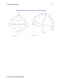
1
TruScan Neurofeedback User guide
TruScan Neurofeedback
2
Table of Contents
Introduction................................................................................................................................................ 4
Warranty.................................................................................................................................................. 5
Trademarks and Regulatory Standards.......................................................................................... 7
About the System and Warnings...................................................................................................... 9
Connecting the Electrodes .............................................................................................................. 12
Basic Steps for Recording ............................................................................................................... 13
Electrode placement according to 10/20 system ....................................................................... 15
Main Interface Controls......................................................................................................................... 16
TruScan Acquisition overview ........................................................................................................ 17
Left panel .............................................................................................................................................. 23
Edit patient's card .............................................................................................................................. 27
Create / Edit Patient's data ........................................................................................................... 30
Move Records screen .................................................................................................................... 32
Event Markers...................................................................................................................................... 35
Cognitive Markers .......................................................................................................................... 37
Recording System .................................................................................................................................. 38
Recording System Tab ...................................................................................................................... 39
Montage Editor ........................................................................................................................................ 43
Montage Editor Screen ..................................................................................................................... 44
create new montage window ........................................................................................................... 47
SETTINGS TAB ........................................................................................................................................ 48
EEG Settings Tab ............................................................................................................................... 49
Modalities ................................................................................................................................................. 51
Copyright 2013 DEYMED Diagnostic
TruScan Neurofeedback
3
BrainFeedback .................................................................................................................................... 52
BrainFeedback Main Tab .............................................................................................................. 53
BFB Main controls ...................................................................................................................... 56
Training settings ......................................................................................................................... 60
Session Info / Spectrum ........................................................................................................... 62
BFB Protocols ............................................................................................................................. 64
Sound............................................................................................................................................. 66
Band ............................................................................................................................................... 68
LCC creator .................................................................................................................................. 70
Copyright 2013 DEYMED Diagnostic
TruScan Neurofeedback
4
INTRODUCTION
Copyright 2013 DEYMED Diagnostic
TruScan Neurofeedback
5
Warranty
Warranty
Deymed warrants that each product we sell you is free from defects in labor and materials and
shall conform to its product specifications as defined in the user documentation. If the product
does not function as warranted during the warranty period, we will repair or replace it without
charge. If in our judgment we are unable to do so, you may return it to us and we will refund your
money.
Warranty Period
The warranty period is stated in the product user documentation. If you install the product, the
warranty period begins on the date of invoice. If we install the product, the warranty period
begins on the date of installation but will begin no later than 30 days from the date of invoice.
The warranty period for products is 12 months from the date of installation or 13 months from the
date of shipment, whichever is less.
Misuse, accident, modification, unsuitable physical or operating environment, improper
maintenance, or damage caused by a product for which we are not responsible may void the
warranty. Certain components may have separate warranty periods as stated in the product user
documentation. Consumables are not covered under warranty.
THIS WARRANTY REPLACES ALL OTHER WARRANTIES, EXPRESSED OR IMPLIED AND
OR ANY OTHER OBLIGATIONS OR LIABILITIES ON THE PART OF DEYMED. WHETHER IN
CONTRACT, WARRANTY, NEGLIGENCE OR OTHERWISE, DEYMED SHALL NOT BE
LIABLE FOR AND DISCLAIMS ALL CONSEQUENTIAL, INCIDENTAL AND CONTINGENT
DAMAGES.
Items Not Covered by Warranty
We do not warrant uninterrupted or error-free operation of a product. We provide certain
non-Deymed products on an “as is” basis. Non-Deymed manufacturers or suppliers may provide
their own warranties to you.
Customer Responsibility
This product and its components will perform reliably only when operated, maintained and stored
in accordance with the instructions contained in this manual, accompanying labels and inserts. A
defective product should not be used. Parts which may be broken or missing or those that are
clearly worn, distorted or contaminated should be replaced immediately with clean, genuine
replacement parts that have been manufactured, supplied or approved by Deymed. The
responsibility of Deymed Diagnostic for a non-functioning product is limited by the warranty set
forth in this guide. Should repair or replacement of this product become necessary after the
expiration of the warranty, the customer should seek advice from Deymed prior to such repair or
replacement. If this product is in need of repair, it should not be used until all repairs have been
made and the unit is functioning properly and is ready for use. The owner of this product has the
Copyright 2013 DEYMED Diagnostic
TruScan Neurofeedback
6
sole responsibility for any malfunction resulting from improper use or maintenance, or repair
done by anyone other than a qualified Deymed Diagnostic representative and from any
malfunction caused by any parts that have been damaged or modified by anyone other than a
qualified Deymed Diagnostic representative.
Attention
The information in this document is subject to change without notice. Deymed Diagnostic s.r.o.
makes no warranty of any kind with regard to this material, including, but not limited to the
implied warranties of merchantability and fitness for a particular purpose. Deymed assumes no
responsibility for any errors that may appear in this document. Deymed makes no commitment
to update nor to keep current the information contained in this document. No part of this
document may be copied or reproduced in any form or by any means without prior written
consent of Deymed Diagnostic.
© 2012, Deymed Diagnostic. All rights reserved.
Copyright 2013 DEYMED Diagnostic
TruScan Neurofeedback
7
Trademarks and Regulatory Standards
Trademarks
Deymed Diagnostic has made every effort to supply trademark information about the products
mentioned in this document.
The following list of trademarks was obtained from various sources:
TruScan Neurofeedback™ is a trademark of Deymed Diagnostic.
Microsoft® is a registered trademark of the Microsoft Corporation.
Windows™ is a trademark of the Microsoft Corporation.
Regulatory Standards
The Deymed TruScan Neurofeedback system meets the following standards set by domestic
and international regulatory agencies for medical electronic equipment:
IEC/EN 60601-1:2006 General Requirements
IEC/EN 60601-1-1:2001 Systems Requirements
IEC/EN 60601-1-4:1996
IEC/EN 60601-2-26:2003
IEC/EN 60601-1-2:2007
IEC/EN 60950-1 ed.2:2006
Compliance
Deymed Diagnostic s.r.o. is an ISO 13485-certified corporation.
TruScan Neurofeedback is a FDA Registered Biofeedback Device (HCC)
The CE 1015 Mark identifies compliance with the Medical Device Directive (MDD) 93/42/ EEC.
The TruScan Neurofeedback is classified as a Class IIa device equipment according to the rules
of the Medical Device Directive (MDD) 93/42/ EEC and a Class II (Special Controls)
Biofeedback Device with the US FDA.
In regards to electrotechnical classification, the TruScan Neurofeedback is classified as a Class I
electrical device (IEC 60601) equipment in which protection against electric shock does not rely
on basic insulation only, but includes a grounding pin on the power cord. For ground reliability
Copyright 2013 DEYMED Diagnostic
TruScan Neurofeedback
8
always plug the power cord into an AC grounded outlet.
Type BF Equipment: The TruScan Neurofeedback is a Type B piece of equipment with an
F-Type applied part. A Type B piece of equipment is one that provides a particular degree of
protection against electric shock, particularly regarding allowable leakage current and reliability
of the protective earth connection (grounding). F-Type applied part is one that extends from the
patient into the equipment and is isolated from all other parts of the equipment.
EMI, by its very nature, can be a source of possible disturbance to electronic equipment.
This device should be used in an environment free* of other equipment that could be affected by
interference.
*Environment free as described in IEC1000-2-3, Part 2, 1992, First Edition.
Copyright 2013 DEYMED Diagnostic
TruScan Neurofeedback
9
About the System and Warnings
About the System
Indication for use: Relaxation training and muscle reeducation.
Hardware: The TruScan Neurofeedback system features a portable battery powered Amplifier
and optically isolated USB adapter to connect to the users computer.
Software: The TruScan Neurofeedback software is designed to be easy to use by implementing
a dashboard style interface with important controls accessable directly on the main interface
screen.
Additional features of the TruScan Neurofeedback system:
FIber Optic isolation and battery operation for superior signal
High Sample rates of all channels at 4,096 Hz per channel
Small footprint and modular for portable use
Installation
Installation is performed via the TruScan Install file name 'TruScan_Install.exe' that is found on
the Install CD that came with the system or downloadable from the Deymed website at
www.deymed.com/support. Start the install by clicking on the TruScan_Install.exe' file and follow
the on-screen instructions.
Any computer may be used provided it meets the following minimum specifications:
at least 250 MB of free hard disc space;
Windows 7 (prefered) or Windows XP;
Intel Dual Core processor or better (or AMD equivalent or better);
2 GB Ram or more for the operating system;
Display native resolution must be at least 1280x900 (be especially careful when
purchasing a laptop to check its native resolution);
3D game graphics: NVIDIA or AMD (ATI) - for Neurofeedback 3D games, Note: Intel
embedded graphics cards may not work properly;
Free USB Port connection;
NOTE: Multi-Parameter DVD Player for Neurofeedback only supported on Windows 7
Entering Commands to the system
You enter commands, text or values by clicking or typing a series keys in the program’s
interface. You may also use a mouse to perform these functions by pointing and clicking on any
key or button listed on the display area.
Copyright 2013 DEYMED Diagnostic
TruScan Neurofeedback
10
User Safety
In this manual, two labels identify potentially dangerous or destructive conditions or procedures:
The WARNING label identifies conditions or practices that may present danger to the
patient and/ or user.
The CAUTION label identifies conditions or practices that could damage the equipment or
cause you to lose data.
A third label, NOTES, helps you identify areas of possible confusion and avoid potential
problems during system operation.
IMPORTANT!
Please read and follow all WARNINGS, CAUTIONS and NOTES provided in this guide. To
avoid the possibility of injury, damage to your TruScan or lost data, observe these safety
precautions during system operation and maintenance. For your information, the
WARNINGS and CAUTIONS provided in this manual are listed on the following pages.
User and System Warnings:
Connect patient electrodes to fully electrically-isolated physiological devices only. Connection of
patient electrodes to any other devices or external electrical outlets may result in personal injury.
Do not operate the device in close proximity (i.e., less than 1 meter) to a shortwave or
microwave therapy device. This practice may lead to electromagnetic interference into the
electrode leads and can cause patient burns.
Using electrodes with current densities greater than 2 mA r.m.s./cm2 may require the special
attention of the operator.
This device is not suitable for use in the presence of a flammable anesthetic mixture with air, or
in the presence of a flammable anesthetic mixture with oxygen or nitrous oxide.
CAUTIONS
Caution: Proper use of this device depends on careful reading of all instructions and labels.
Caution: Rx Only. Federal law restricts this device to sale by or on the order of a liscenced
health professional.
Caution: EU Only: All non-medical equipment connected to this device, such as printers, must
comply with IEC900 and/or all European Directives. All non-medical devices must be connected
to a medical use certified Isolated Power Supply.
Copyright 2013 DEYMED Diagnostic
TruScan Neurofeedback
11
Preventive Maintenance
Preventive maintenance for the Deymed TruScan Neurofeedback system consists of periodically
cleaning and visually inspecting the exterior of the instrument. Deymed Diagnostic recommends
that the typical user follow the preventive maintenance schedule presented in TruScan
Neurofeedback Service Manual. Your own schedule may vary based on the type and amount of
instrument use.
Additional Copies
Additional copies of this user guide and/or other Deymed Diagnostic literature may be obtained
from:
Deymed Diagnostic USA
1720 N. 7th Ave
Payette, ID 83661
Phone: 1-208-642-9300
Fax: 1-212-504-3290
Copyright 2013 DEYMED Diagnostic
TruScan Neurofeedback
12
Connecting the Electrodes
Connecting the Electrodes
The following instructions explain how to connect the recording electrodes to the appropriate
TruScan Neurofeedback system components.
Position the electrodes on your patient according to your own conventions.
Recording Electrodes:
Position the recording electrodes on the patient or place the FlexiCap recording cap on the
patient.
If using individual electrodes, connect them to the amplifier as described in the 'Individual
Electrodes Connection to TruScan Neurofeedback inputs' chart below.
When using 9mm disc electrodes with touch proof connectors, plug the touch-poof connectors
into the corresponding openings with the pins on the front of the amplifier.
When using the FlexiCap recording cap, plug the cap 25 pin connector into the CAP connector
'Canon 25f' connector on the TruScan Headbox.
Individual Electrodes Connection to TruScan Neurofeedback inputs
Electrode
Patient Ground
Reference Channel
Active Channels
Copyright 2013 DEYMED Diagnostic
Amplifier Channel Connector
Green 'PG' pin jack
Purple 'REF' pin jack
Red,Light Blue and Orange pin jacks
TruScan Neurofeedback
13
Basic Steps for Recording
Patient Hookup with Recording Cap
1. Scrub the patient's ears and forehead with Nuprep and wipe off with an alcohol swab.
2. Measure the circumference of the patient's head in order to choose the right recording
cap:
Green(47-51 cm)
Yellow(51-55 cm)
Red(54-58 cm)
Blue(59-63 cm)
3.
Put the cap on the patient's head with the tag in the back.
Make sure FZ, CZ, PZ are centered
Make sure that CZ lines up with the ears
4.
ears
If using ear electrodes, place tin ear clip electrodes, filled with gel, onto the patient's
5.
If using ear electrodes, plug ear electrodes into ear sockets in cap, or if cap does not
have ear connectors, plug into A1 and A2 sockets on Headbox.
6.
If the recording cap is not a Deymed brand cap, place a ground electrode, filled with
paste, onto the patient's forehead, in the center of FP1 and FP2, and plug the electrode into the
green 'PG' slot on the TruScan Headbox.
7.
Plug the cap into the Headbox via the 25 pin connector, preferably using the included
wear and tear extension cable to protect the Headbox connector from overuse.
8.
Put gel into every hole in the cap but be careful not to overfill. If gel runs down from one
electrode to the other, they will short (create a bridge between the two electrodes) and the signal
be the same at both locations.
9. Check the impedances, including the ground, are below 10Kohm or show as Blue or Green on
the impedance display. If any channel is not showing Blue or Green, then the connection is
most likely not low enough and precaution should be taken to further lower the impedance. TIP:
take the end of the wooden Q-tip and twist around in the corresponding hole on the cap for the
problem electrode. You can also add more gel if necessary being careful not to overfill.
Setup of Patient for Training or Recording
1.
From the Edit Patient's Card tab, add a new patient. Fill in the name fields. Give the
patient an ID number. The number can not include Alpha characters or spaces or other
non-numeric characters.
2.
Set the montage to the preferred montage* (on the left side on the screen next to the
record and stop buttons). During patient preparation, the REF montage is preferred due to the
ability to see each active channel individualy to the Hardware reference channel.
Copyright 2013 DEYMED Diagnostic
TruScan Neurofeedback
14
3.
Set the sensitivity to 70µV to start if not set to that value. You may reduce or increase
this setting during recording or training to facilitate a better visualization of the brainwaves. Note
that this setting does not affect the actual stored data.
4.
Hit 'Record' when the patient is ready with clean signal that is mostly free of large EMG
or other signal artifacts.
5.
During the recording or training, look for EMG or movement artifact in the recording and
if necessary pause and coach the patient to remove this artifact.
6.
After desired amount of training or recording minutes, hit the 'Stop' button (located
below the Pause button).
7.
The Patient may now be disconnected and cleaned up. You may now exit the TruScan
software.
* The Montage selection is only for viewing purposes. You can change the Montage at any time
during or after the recording with no change or affect to the recorded data.
Copyright 2013 DEYMED Diagnostic
TruScan Neurofeedback
Electrode placement according to 10/20 system
Copyright 2013 DEYMED Diagnostic
15
TruScan Neurofeedback
MAIN INTERFACE CONTROLS
Copyright 2013 DEYMED Diagnostic
16
TruScan Neurofeedback
17
TruScan Acquisition overview
Left panel
Copyright 2013 DEYMED Diagnostic
TruScan Neurofeedback
18
In the left panel, a user can control the recording and change recording settings. The
controls include the record, pause and stop button. Other control or settings buttons
include the timebase, sensitivity, filters and montage controls. All of these recording
settings however do not affect the actual recorded signal if changed during recording. All
signal is recorded to its full bandwidth according to the sample rate set on the 'Recording
System' page. The number of channels recorded is also set on the 'Recording System'
Copyright 2013 DEYMED Diagnostic
TruScan Neurofeedback
19
tab. Click here for more information on the 'Recording System' settings.
For more in depth details on this panel go to Left panel section of this user manual.
Impedance Panel
The impedance panel is one of the most important and useful tools in the TruScan Acquisition
program. It shows the impedance status of all channels at all times before and during the
recording. The impedance for each site is indicated by a number and by the color changing for
each individual location. Numerical values representing the impedance are shown in kilo-ohms.
The colors used for the various impedance ranges are shown below.
Blue
Green
Yellow
Red
< 5 kOhms
5 kOhms to 10
kOhms
11 kOhms to 30
kOhms
> 30 kOhms
High Quality Connection (very low impedance)
Good Connection
Poor Connection
Unusable connection or electrode disconnected
TIP: Methods of Fixing Poor Impedance
1.
Using a Q-Tip, remove bubbles in the gel inside the electrode, by gently inserting the
wooden end and twisting.
2.
Grab the electrode body between finger and thumb and massage in a circular motion to
remove hair from under the electrode.
3.
Check the Ground and Reference electrodes as these affect the impedance for every
electrode. The Reference electrode is built into the cap at FPz, but does not have it's own
readout on the Impedance Meter.
4.
Add more gel to ensure a good connection. Too much gel can short electrodes together
reducing the signal from both sites.
Modalities
Copyright 2013 DEYMED Diagnostic
TruScan Neurofeedback
The modalities panel allows the user to select from a set of various functions or
additional tests available in the TruScan Acquisition program.
You can find more details on each individual test or program here :
qEEG
BFB
Cognitive Markers
Event Markers
For more details go to Event Markers
Exit / Minimize
Exit Button:
Used to exit the program, and shut down the Headbox.
Minimize:
Minimize the TruScan to a system taskbar.
Signal screen
Copyright 2013 DEYMED Diagnostic
20
TruScan Neurofeedback
21
This is the main signal screen where the signal will appear. The channel configuration is
set by the selected montage. In TruScan Acquisition, there will be yellow lines in place of
signal if the impedances are not below 50 KOhm. This helps prevent users from
mistaking noise as real signal in the event that any electrodes lose contact during
recording. There is an option to turn off this impedance check with yellow lines in the
recording system tab.
Screens
For more details go to the following sections in this user manual:
Edit patient's card
Recording system
EEG settings
Copyright 2013 DEYMED Diagnostic
TruScan Neurofeedback
22
Patient card
the patient card area allows the user to input patients into the database or easily search
the database for existing patients. There is also a recordings list and notes section.
For more details go to Patient card.
Copyright 2013 DEYMED Diagnostic
TruScan Neurofeedback
23
Left panel
Selected patient
This area displays the currently selected patient for recording.
Copyright 2013 DEYMED Diagnostic
TruScan Neurofeedback
24
Record / Pause / Stop
From here the recording can be Started, Paused and Stopped. When using the pause
button, and then resuming the recording by hitting the Record button again, the
recording is still the same file. If the user clicks on the 'Stop' button this will end the
recorded file. The user may pause and continue the recording as many times as they
wish.
Recording Progress
This area displays the recording status. During recording the message 'Recording' will
be displayed. If the recording has stopped, the message 'Stopped' will be displayed. If
the recording is paused the message 'Paused' will be displayed.
Paper Speed
Legacy measurement of the speed at which the signal traverses the screen. Speeds of
15, 30, 60 and 120mm/sec are available. 30mm is Default.
Sensitivity / HP and LP filter
Sensitivity:
Sets the sensitivity of the signal displayed. Sensitivity is adjustable from 20µV to 999µV.
A default of 70µV is used. A setting of 70µV should be set to give a clear reading of each
Copyright 2013 DEYMED Diagnostic
TruScan Neurofeedback
25
of the recording channels being used. Adjusting the sensitivity setting has no effect on
the signal that is recorded to the hard disk.
Highpass Filter:
This sets the cut-off for the highpass filter of the signal readout. Frequencies under this
setting will not be displayed. This default setting is 0.5 Hz but no highpass setting will
affect the recorded signal.
Lowpass Filter:
This sets the cutoff for the lowpass filter of the signal readout. Frequencies above this
setting will not be displayed. This is normally set to 35 Hz but no lowpass setting will
affect the recorded signal.
Montage selector
Pre-set montages are selectable by icon or by this drop-down menu. If an icon has not
been set for a montage the name of the montage will always be listed in this drop-down
menu.
Montage selection
Pre-set montages are selectable by clicking on its icon or via the drop-down menu. Each
montage may also be selected by clicking on the corresponding number displayed in the
top right-hand corner of the montage icon.
Montage editor
Montages can be created or edited in this section.
Copyright 2013 DEYMED Diagnostic
TruScan Neurofeedback
26
Zoom
Toggles the wide-screen view of the signal display.
EEG system
Hard Drive Free space:
Shows the amount of free space on the currently selected drive.
Battery Condition:
Shows the battery condition of the device. The battery should last for up to at least 120
hours of continuous recording. Even a low battery state will not affect the recording. It is
recommended to recharge the battery, however, any time the battery is below 10%
charge. A full recharge the battery should not be more than four hours. When the battery
is charging, it may take up to one or two hours before the LED light will start blinking
again on the headbox, which is normal
Headbox icon:
The headbox icon shows a green checkbox next to the icon when the system can detect
and communicate with the headbox. If the green checkbox is not visible, the system is
not connected correctly and you will not be able to record. You may double-click on this
icon to reboot the headbox.
Copyright 2013 DEYMED Diagnostic
TruScan Neurofeedback
27
Edit patient's card
New / Edit patient
New Patient button:
Opens the “Work with Patient's Data” dialogue box to enter a new patient.
Edit Patient's Card button:
Opens the “Work with Patient's Data” dialogue box for the currently selected patient.
Patient list
Copyright 2013 DEYMED Diagnostic
TruScan Neurofeedback
28
Shows the current patients in the system sorted alphabetically, ascending by surname.
Searching the Patient database:
Search the patient database, by clicking the column that you would like to search and
start typing. The results will sort based on what you type, allowing you to quickly find the
patient you are looking for. At the bottom of this window you will see the letters or
characters as you're typing them. To correct your typing, you may use the Backspace.
Move / Delete Records
Move Rec. button:
Opens the “Move Record” dialogue box. This dialog box allows you to move a recording
to a new patient in the event that a recording was made on the wrong patient name.
Delete Rec. button:
Opens the “Delete Files” dialogue box. This dialog will allow you to delete recordings but
only after a series of confirmations to be sure no file is accidentally deleted.
Recordings list
Copyright 2013 DEYMED Diagnostic
TruScan Neurofeedback
29
Shows the recordings available in the system for the currently selected patient. the
columns include duration, indicating the length of recording, the date and time of the
recording, the file name of the recording and the type of record. The type of record may
be EEG or BFB depending on which modality tab is selected at the time of recording.
Notes
Use this for general notes for each recording. Notes typed here are specific to each
recording. the notes entered here will also be available in the interpretation editor in
TruScan Explorer.
Copyright 2013 DEYMED Diagnostic
TruScan Neurofeedback
30
Create / Edit Patient's data
Patien card
Insert patient Name and Identification number. Only a Name and patient ID is required to
create new patient card. The patient ID will be automatically populated by the system,
but the user may choose to edit this field with a different ID number. An ID number
cannot be duplicated in the system. The ID number may not contain characters or
spaces.
Copyright 2013 DEYMED Diagnostic
TruScan Neurofeedback
31
Patient details
Use this area to add patient's insurance number, his/her physician, notes and type of
medication. The referring doctor or department may also be included.
OK / Cancel
Click okay to save any changes or cancel to leave without saving changes.
Copyright 2013 DEYMED Diagnostic
TruScan Neurofeedback
32
Move Records screen
Moved record
This area indicates what signal recording is being moved.
Patient list
Copyright 2013 DEYMED Diagnostic
TruScan Neurofeedback
33
New file time / date
The new file time and date dialog allows you to change the date and recording time of
the recording in the event that the settings were wrong during acquisition.
Copy / Move / Cancel
The copy move or cancel dialog allow the user to copy or move the selected file. If the
user wishes to quit the operation without moving or copying the file he can choose
Copyright 2013 DEYMED Diagnostic
TruScan Neurofeedback
cancel.
Copyright 2013 DEYMED Diagnostic
34
TruScan Neurofeedback
35
Event Markers
F1 to F8 Markers
It is possible to pre-define event markers for buttons F1 through F8. Click on the area
next to the button you wish to set, and type the event description (i.e. eye blink). During
recording the user can click on the corresponding function key from the computer
keyboard to insert marker or click on the function key in the software interface via the
mouse to insert the marker.
Timed Duration Event Markers
The time and duration event markers are used to insert start and stop markers for a
defined time interval. The marker names for the start and stop positions can be
designated as well as the amount of time via the drop-down menu. A final marker may
be also placed after a set duration occurring after the first stop marker. This marker is
sometimes referred to as the stop+ marker.
These timed events are displayed in the TruScan Explorer review by highlighting the
signal in between these intervals.
Copyright 2013 DEYMED Diagnostic
TruScan Neurofeedback
36
F11 Marker
The F11 Marker allows the user to insert any random text during the recording. Once this
button is pressed the user may type any text and and have that text inserted at the time
that the button was first pressed, regardless of how long it takes to type the event or
note.
Copyright 2013 DEYMED Diagnostic
TruScan Neurofeedback
37
Kognitive Markers
Block Markers
Notes
Copyright 2013 DEYMED Diagnostic
TruScan Neurofeedback
38
RECORDING SYSTEM
Copyright 2013 DEYMED Diagnostic
TruScan Neurofeedback
39
Recording System Tab
Recording systems
Copyright 2013 DEYMED Diagnostic
TruScan Neurofeedback
40
The recording systems that are offered by default in the system are shown here. The
recording system dictates what channels are recorded and the label name for each
channel. The three standard recording systems are displayed, with an additional
drop-down menu that shows some additional recording systems. These recording
systems are permanent and cannot be changed.
Custom recording system
The user may add and customize as many recording systems as they like in this area.
To save a new recording system, the user can type a name in the top left-hand area, set
the number of electrodes, name the electrodes according to the channel number, and
then click the save button (the wrench and hammer button).
Custom recording system creator
Copyright 2013 DEYMED Diagnostic
TruScan Neurofeedback
41
When creating custom recording system options, you have the ability to name the
electrodes by selecting and editing the electrode names in this column.
Data format
The TruScan Neurofeedback system always records with a sample rate of 4096 Hz but
the data saved to the hard disk is lowered to a more manageable size with the help of a
DSP processor. The data format or saved data rate can be set in this area. Due to the
DSP optimization, a stored sample rate of 128 Hz will provide a bandwidth up to 52 Hz.
With a data sample store rate of 256 Hz, the bandwidth goes up to 102 Hz. with a
sampling stored data rate of 1024 Hz, the bandwidth goes up to 460 Hz. This is the
maximum stored bandwidth available.
By default the system uses the 128 Hz sample store rate.
Headbox activator
The TruScan Acquisition software can handle up to two had boxes simultaneously. They
Copyright 2013 DEYMED Diagnostic
TruScan Neurofeedback
42
can both be turned on at the same time or each one individually. This allows for up to 64
channels using two 32 channel headboxes.
Calibration / Impedance check
Impedance check:
When this button is pressed, any signal above 50 kOhms is shown as straight yellow
lines. This is the default setting. when this button is not pressed, any signal or noise
entering the amplifier inputs will be displayed regardless of the impedance. The purpose
of this feature is to help prevent the user from mistaking a badly connected electrode as
giving good signal, thus the yellow lines are displayed to show the user that the
impedance is too high to give a good signal.
Calibration:
The calibration button when selected inputs an 8 Hz square wave into all input channels
of the system. This can be used to ensure that the amplifier is properly calibrated.
Change recording date / time
The change recording date and time settings can be used to change the date and time of
the recorded data instead of using the date and time of the Windows operating system.
Copyright 2013 DEYMED Diagnostic
TruScan Neurofeedback
43
MONTAGE EDITOR
Copyright 2013 DEYMED Diagnostic
TruScan Neurofeedback
44
Montage Editor Screen
Add / Remove/ re-order montage
Add a new Montage:
Create a new montage by clicking on the plus sign. See the add new montage dialogue
in the create new montage section of this user manual.
Delete montage:
Delete the currently selected montage.
Re-order montage:
Move the selected montage up or down in the list.
Copyright 2013 DEYMED Diagnostic
TruScan Neurofeedback
45
Montage list
Montage list shows two columns. The first column named 'icon' shows the name of the
icon used to represent the montage on the main recording screen. There are preset
icons in the system that can be used but any bitmap can be used as an icon as long as it
is the same size as the current bitmap icons. The 'name' column shows the name of the
montage. This name will be shown in the drop-down list when choosing montages.
Global Settings
Global settings allow the user to quickly set all electrodes in a montage to the same
value. This applies to the reference channel, sensitivity, high pass, low pass and polarity
settings. The user may also globally set the color of the traces or designate the traces as
polygraph channels. A polygraph channel is a channel that has fixed settings that do not
change when the user changes global properties such as sensitivity or filters during
recording.
Copyright 2013 DEYMED Diagnostic
TruScan Neurofeedback
46
Add / Remove Channel
The user may click on the plus or minus sign to add or remove a channel from the
current montage.
Channels
The channels area shows each channels settings including the active channel, the
reference channel, sensitivity, high pass, low pass, polygraph and color settings. Any
setting can be quickly changed by double-clicking in the cell and a drop-down menu or
additional screen will show the options for that cell. To designate the channel to be a
polygraph channel, meaning a non-EEG channel, just check the checkbox in the
polygraph column.
Copyright 2013 DEYMED Diagnostic
TruScan Neurofeedback
47
create new montage window
Number of channels
Select a number of channels to be included in your montage.
Montage name
Choose the name of your new montage by editing this area to the name of your choice.
Copyright 2013 DEYMED Diagnostic
TruScan Neurofeedback
48
SETTINGS TAB
Copyright 2013 DEYMED Diagnostic
TruScan Neurofeedback
49
EEG Settings Tab
Info Area
The Info Area gives the following informaion:
PC-USB adapter: This is the Serial Number of the USB Adapter which is used when
generating unlock codes for various TruScan features.
Data frame: This is used by a Deymed technician in case of troubleshooting the USB
adapter. Users should not be concerned with this value.
Number of DSPs: This is used by a Deymed technician in case of troubleshooting the
USB adapter. Users should not be concerned with this value.
Headbox: This is the name of the Headbox that is currently connected.
Record creating
Record Identifier:
Copyright 2013 DEYMED Diagnostic
TruScan Neurofeedback
50
set the letter that you want the record name to begin with;
EEG dbf:
Set the folder to which the patient database will be saved;
Record Path:
Set the folder to where the records will be saved;
Network Store:
When working with a network drive, set a folder where the records will be saved.
To save any changes, click the hammer/plier button
Configuration code
Type in a code to activate additional features such as Brainfeedback with 3D games,
UDP output for Neuroguide or other Deymed features.
Language selection
Choose a language for the program.
Stimulator / UDP
Stimulator: The Stimulator setting is used in scenarios for research VEP or P300. This
is set with the help of a Deymed technician.
UDP output Purchased: This is used by a Deymed technician in case of
troubleshooting the USB adapter. Users should not be concerned about this value.
VEP
Test external VEP stimulator (external stimulator required). This setting is only to be
used with the help of a Deymed technitian.
Copyright 2013 DEYMED Diagnostic
TruScan Neurofeedback
51
MODALITIES (add-ons)
Copyright 2013 DEYMED Diagnostic
TruScan Neurofeedback
52
BRAINFEEDBACK
Copyright 2013 DEYMED Diagnostic
TruScan Neurofeedback
53
BrainFeedback Main Tab
Training Settings
For more information, see the Training Settings section of this user manual.
info screen/spectrum
Copyright 2013 DEYMED Diagnostic
TruScan Neurofeedback
54
For more information, see the Info / Spectrum section of this user manual.
Protocol/Sound/Band/LCC Window
For more information, see the BFB Protocols , Sound, Band or LCC Creator section of
this user manual.
Main BFB Screen
Copyright 2013 DEYMED Diagnostic
TruScan Neurofeedback
For more information, see the Main BFB Screen section of this user manual.
Copyright 2013 DEYMED Diagnostic
55
TruScan Neurofeedback
56
BFB Main controls
The BrainFeedback training screen is a unique single screen neurofeedback interface designed
to make the use and control of neurofeedback sessions as easy as possible.
Reward Band Window
Up to two reward bands can be set, one for the left and right column. By default a single
reward parameter is active, which is in the left column. The reward columns are easily
identifiable by their green color. Each protocol settings window can use the same, or
different electrodes and the same, or different Bands.
EEG Inhibit Band Window
Copyright 2013 DEYMED Diagnostic
TruScan Neurofeedback
57
The EEG inhibit band is colored orange and is used to inhibit any EEG band that the
user sets. A second EEG inhibit band can be set by activating the additional EEG inhibit
window to the right. Each protocol settings window can use the same, or different
electrodes and the same, or different Bands.
Artifact Inhibit Band Window
The artifact inhibit band is colored red and is used to inhibit any EEG artifact band that
the user sets. A second EEG Artifact inhibit band can be set by activating the additional
EEG Artifact inhibit window to the right. Each protocol settings window can use the
same, or different electrodes and the same, or different Bands.
Electrode selector
The electrode selector designates the electrode montage used (from the drop-down
menus) for the right or left column protocol window settings.
Band Selector
The band selector Is used to designate the training band for the reward parameter. All
bands that are created in the system are shown from this drop-down menu.
Training type
The training type menu shows the various types of biofeedback training that can be
used.
Copyright 2013 DEYMED Diagnostic
TruScan Neurofeedback
58
Amplitude: Amplitude training is the most standard and basic training type where the
protocol parameters are based on being above or below a set microvolt (uV) threshold.
Coherence: Coherence training is a type of training that rewards the user for increasing
or decreasing the coherence between two EEG or LCC electrodes (between active and
reference electrodes). The values are shown in percentages, with higher percentages
being greater coherence and lower percentages being less coherent between the two
electrode sites.
Z-Amplitude: Z-Score amplitude training uses the neuroguide Z score DLL to calculate
real-time Z scores for the selected electrodes and bands. (the Z score training module is
optional and must be purchased). Thresholds can be set to a maximum Z score value
between plus and minus three. Only the reward band uses the instantaneous Z score
values, and the EEG inhibit and EEG artifact channels are still based on standard
amplitude microvolt values.
Reward Up or Down
The reward of up or down arrow can be toggled to indicate whether the goal of training
should be to increase or decrease the activity in the reward band. In Z score training, this
arrow should always be pointed down.
Scale
The scale area for each protocol window settings allows a user to adjust the threshold
manually by dragging the control arrow up or down on the y-axis indicating the desired
microvolt threshold. This can be set from 5 to 999 uV or from 0 to 100% in coherence
training. In the Z score training, the Y axis is 0 to 3 indicating the maximum threshold for
both the plus and minus Z score values on the same y-axis.
The drop-down menu at the top left of this screen allows the user to change the upper
limit value for the protocol window. Typically this value is set to roughly double the value
of the current activity for its window, thus allowing the user to have a better view of the
data.
Thresholds control
In each training window there is a threshold level control. The threshold level is set by
either dragging the indicator with your mouse or with the keyboard up/down arrows.
The user will typically set the threshold below the average microvolt value for reward, in
Copyright 2013 DEYMED Diagnostic
TruScan Neurofeedback
59
the case of up training, and and set the inhibit threshold slightly above the average
micro vault value for inhibits.
Current / Average amplitude
Each protocol window displays the instantaneous and average microvolts values at the
top right-hand corner of the window. The average is taken from the start of each round.
Active / monitor only
This button when turned on and is active, enables the protocol window to be an active
part of the protocol. The protocol window will no longer be grayed out indicating the
window is in use. When the window is not active, The activity will not be part of the
protocol, but the values will be stored for monitoring purposes.
Copyright 2013 DEYMED Diagnostic
TruScan Neurofeedback
60
Training settings
Rounds
Total rounds setting:
This setting determines how many rounds are in a session.
Round duration:
Define the duration of each round.
Auto next:
When selected, there will be a ten second pause at the end of each round and then the
new round will start automatically.
Averaging
Averaging is a method to fine tune the difficulty level of the training. To understand this
setting it is important to know that a patient is rewarded when their amplitude is above
Copyright 2013 DEYMED Diagnostic
TruScan Neurofeedback
61
the reward threshold for at least one half second. Their amplitude is calculated 16 times
per second, so this means that all 8 values (8 values per .5 second) must be above the
threshold to get the point. These values need to be averaged due to the fact that EEG is
highly erratic. The lower the number the less averaging, ie, with a lower number setting
it becomes more difficult to score because there is less averaging (but the games are
more reactive to the instantaneous movements of the EEG). Typically a value of 3 to 5 is
generally used.
The scale works as follows.
1 is more reactive, sharp and jerky, more difficult to score
10 is less reactive, slow and lethargic, but easier to score
3D Games
3D Games selection:
List of 3D Games. After selecting the game from the drop-down menu it will show up on
your monitor or on your second monitor if connected.
Show Relax:
When “show relax” is selected, a relax message will be displayed on the game screen
when the artifact inhibit amplitude is above its threshold, indicating increased muscle or
EOG activity (depending on the band set), which can interfere with the EEG
measurements.
2D games
Used only for the 2 computer version of legacy 2D games.
Copyright 2013 DEYMED Diagnostic
TruScan Neurofeedback
62
Session Info / Spectrum
Time
Shows the actual time in the round. If the round has not been started, then this area will
show the word 'Demo' meaning that the system is active but not recording.
No. of Rounds / Score
Rounds:
Shows the current round number.
Score:
Displays the score of the current round.
Auto threshold
Auto or percent threshold activates the use of an automatic threshold calculation (based
on a percentage setting) to determine the threshold for one of the training parameters,
either reward, EEG inhibit or artifact reject parameter.
Spectrum
Displays the instantaneous amplitude spectrum from 0 to 50Hz. The electrode montage
as set for the left or right group of training parameters is used. The user may choose the
Copyright 2013 DEYMED Diagnostic
TruScan Neurofeedback
63
right or left set of training parameters as the input for this display by clicking on the
drop-down menu and choosing right or left.
Z-score Activation
In order to use Z score training, this module must be purchased and activated. Once a
license is purchased the user can use the activate button to unlock this feature. Further
instructions are shown once this dialogue is open.
Copyright 2013 DEYMED Diagnostic
TruScan Neurofeedback
64
BFB Protocols
New / Edit / Delete
To create a new protocol click the new button. To edit any protocol select that protocol
from the list and click edit. This will allow changes to be made to the protocol directly on
the screen. To delete a protocol, select that protocol from the list and click on the delete
button.
Protocol list
Copyright 2013 DEYMED Diagnostic
TruScan Neurofeedback
65
Protocol list shows all protocols that have been created in the system. To select a
protocol for training, simply click on the protocol name. This will set the parameters for
training to the parameters that were saved for this protocol. If migrating custom user
settings or protocols from one computer to another, please contact Deymed support for
help.
Copyright 2013 DEYMED Diagnostic
TruScan Neurofeedback
66
Sound
Main Sound
The main reward sound used for neurofeedback training can be set by choosing a wave
file from this drop-down menu. If the user would like to use a midi sound instead of one
of the preset wave files, click on the midi name from this list and then set your midi
settings from the midi setup screen below.
MIDI sound creator
Copyright 2013 DEYMED Diagnostic
TruScan Neurofeedback
67
The MIDI setup window allows the user to choose from various instruments and octave
settings to save as a MIDI sound for training. The string parameter shows what settings
have been selected. The duration of the MIDI sound can also be set in milliseconds from
this screen. Once a MIDI sound has been created as a string, you can save the string as
a favorite sound, by clicking on the 'add to favorites' button. To test the sound before
saving, click on the play button at the bottom right-hand corner to hear the sound from
your computer speakers.
Select sound
Reward 1 shows the main reward sound for neurofeedback training. It is possible to
have two reward sounds (set in the protocol setup), in which case the second reward
sound can be designated here as Reward 2.
Copyright 2013 DEYMED Diagnostic
TruScan Neurofeedback
68
Band
NEW / DELETE
To create a new or custom band for use in neurofeedback training click on the 'new'
button. The system will prompt you for a name for the band and then will allow the user
to edit the frequency range of that band from the drop-down menus 'from' and 'to'. There
are numerous preset bands in the system which are not editable.
Band settings
When creating a new band, set the band range by using the 'from' and 'to' drop-down
menus.
Bands list
Copyright 2013 DEYMED Diagnostic
TruScan Neurofeedback
The Bands list shows all bands currently in the system, both preset, and custom.
Copyright 2013 DEYMED Diagnostic
69
TruScan Neurofeedback
70
LCC creator
The LCC Creator allows the user to configure a synthetic electrode for the purpose of combining
channels into one training channel or electrode.
Electrode name
The LCC electrode names are presets but can be edited to any name.
Electrodes list
Select all available electrodes from this drop-down list. Click on the desired electrode
and press the red '+' button to add it to the currently selected LCC channel.
Copyright 2013 DEYMED Diagnostic
TruScan Neurofeedback
ADD / Remove electrode from the list
Use the plus and minus buttons to add or delete individual electrodes from an LCC
group.
Copyright 2013 DEYMED Diagnostic
71