1
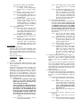
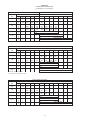
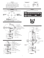
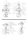
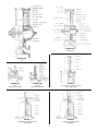
DFAMM-01
DIA-FLO ® & PURE-FLO ®
Diaphragm Valves
Instruction Manual
With Dia-Flo Actuator ®
This manual provides installation and maintenance
instructions for DIA-FLO ACTUATOR operated
DIA-FLO/PURE-FLO diaphragm valves.
If additional information is required, contact:
ITT INDUSTRIES VALVES AND VALVE ACTUATORS ARE DESIGNED AND MANUFACTURED USING GOOD WORKMANSHIP AND
MATERIALS, AND THEY MEET ALL APPLICABLE INDUSTRY STANDARDS. THESE VALVES ARE AVAILABLE WITH COMPONENTS OF
VARIOUS MATERIALS, AND THEY SHOULD BE USED ONLY IN SERVICES RECOMMENDED IN OUR PRODUCT CATALOG OR BY A
COMPANY VALVE ENGINEER.
MISAPPLICATION OF THE PRODUCT MAY RESULT IN INJURIES
OR PROPERTY DAMAGE. A SELECTION OF VALVE COMPONENTS
OF THE PROPER MATERIAL CONSISTENT WITH THE PARTICULAR
PERFORMANCE REQUIREMENTS, IS IMPORTANT FOR PROPER
APPLICATION.
EXAMPLES OF THE MISAPPLICATION OR MISUSE OF ITT INDUSTRIES VALVES INCLUDE USE IN AN APPLICATION IN WHICH
THE PRESSURE/TEMPERATURE RATING IS EXCEEDED OR FAILURE TO MAINTAIN VALVES AS RECOMMENDED.
IF VALVE EXHIBITS ANY INDICATION OF LEAKAGE, DO NOT OPERATE. ISOLATE VALVE AND EITHER REPAIR OR REPLACE.
Engineered Valves
33 Centerville Road
Lancaster, PA 17603
(717) 509-2200
Attention: Sales Department
CONTENTS
1.0 INSTALLATION
2.0 OPERATION & ADJUSTMENT
3.0 MAINTENANCE
4.0 ACCESSORIES
4.1 PRESSURE CAP
4.2 TRAVEL (CLOSING) STOP ADJUSTMENT
4.3 HANDWHEEL OPENING DEVICE OPERATION
4.4 WRENCH OPENING DEVICE OPERATION
4.5 COMBINATION HANDWHEEL OR WRENCH
OPENING DEVICE WITH ADJUSTABLE OPENING STOP
4.6 HANDWHEEL CLOSING DEVICE AND
ADJUSTABLE OPENING STOP
4.7 MICROSWITCH LIMIT SWITCHES ADJUSTMENT
4.8 WESTLOCK MODULE 3 LIMIT SWITCHES
4.9 POSITIONERS (TOP MOUNTED)
TABLES
1. BONNET FASTENER TORQUES
2. VALVE AND ACTUATOR TRAVEL
3. ACTUATOR INTERNAL DATA
4. VALVE OPERATING PRESSURES
5. O-RING SIZES
FIGURES
1. GLASS LINED BODY INSTALLATION
2. VALVE DIAPHRAGM IDENTIFICATION
3. ACTUATOR DIAPHRAGM IDENTIFICATION
4. ACTUATOR DRAWINGS
5. POSITION INDICATORS
6.
7.
8.
9.
10.
11.
12.
13.
14.
TRAVEL STOPS
HANDWHEEL OPENING DEVICE
WRENCH OPENING DEVICE
COMBINATION HANDWHEEL OPENING OR
WRENCH OPENING WITH ADJUSTABLE OPENING
STOP
HANDWHEEL CLOSING DEVICE AND
ADJUSTABLE OPENING STOP
LIMIT SWITCHES - PUSHBUTTON TYPE
LIMIT SWITCHES - WESTLOCK PROXIMITY TYPE
POSITIONERS (TOP MOUNTED)
PTFE DIAPHRAGM DETAIL
1.0 INSTALLATION
NOTE: WELD END VALVES
Weld end valves for schedule 10 and heavier pipe require bonnet and diaphragm removal prior to welding
in line. See Section 3.5, 3.6, 3.7 or 3.8. Schedule 5 and
lighter pipe and tubing may be welded with automatic
equipment only without removing the diaphragm.
Manual welding requires bonnet and diaphragm removal for all pipe schedules.
NOTE: GLASS LINED BODIES
Glass lined bodies have special installation instructions - See section 1.3.
NOTE: SOLID PLASTIC VALVES
Solid Plastic Valves are not recommended for installation
in plastic lined piping systems. Also note threaded inserts
are supplied in the base of the valve body and should be
used for bracketing/supporting valves in accordance with
cGMP’s.
1. INSTALLATION
1.1 Dia-Flo diaphragm valves may be installed in
any orientation. For horizontal piping systems
to be drained through the valve, install the valve
2.
3.
stem between 0 and 30 degrees above horizontal. (After draining, a small pocket of fluid may
remain in the valve.) Note: Pure-Flo valves have
either raised hash marks (castings) or small
machined dots (forgings) on the valve body to
indicate the correct drain angle. Locate these
marks at the 12 o’clock position to achieve the
optimum drain angle.
1.2 Prior to pressurization (with the valve open),
tighten the bonnet nuts in a crisscross pattern
in accordance with Table 1. Retightening 24
hours after the system reaches operating
temperature and pressure is recommended. If
leakage occurs at the body/diaphragm seating
area, immediately depressurize system and
tighten bonnet nuts as noted above. If leakage
continues, diaphragm replacement is required.
Follow applicable steps in Section 3.5, 3.6, 3.7
or 3.8.
1.3 INSTALLATION - GLASS LINED VALVE BODIES
It is extremely important that all glass lined
valves be installed with proper end flange
gaskets and that proper torque be applied to
the bolts in correct sequence. The use of PTFE
plastic envelope gaskets with soft insert
materials is recommended. See Figure 1 for
proper bolt torque and sequence.
1.4 The travel stop, if equipped, is factory set and
should not require adjustment at time of installation. However, if adjustment is required, see
section 4.2.
1.5 Maximum valve operating pressures are shown
in Table 4. Consult factory or Engineering
Catalog for vacuum operation.
1.6 Air line connections should be made up with
care as damage may occur to the standard
aluminum actuator covers. Connection size is
1/4" NPT for #12 through #75 and 1/2" for #101
through #250.
OPERATION & ADJUSTMENT
2.1 The Dia-Flo actuator is a spring-and-diaphragm,
or double acting diaphragm, pneumatic actuator. The actuator model number is located on
the ITT i.d. tag. The model number is a four or
five digit number defining the actuator as
follows:
XXYYY
if XX = 31 Direct Acting (Spring to
Open)
if XX = 32 Reverse Acting (Spring to
Close)
if XX = 33 Double Acting
YYY = Nominal Size. Available sizes
(approximate effective diaphragm area):
#12, 25, 50, 75, 101, 130, 250. For two digit
sizes, the final Y is left off.
2.2 Maximum permitted air supply pressure is 85
psig (586 kPa).
2.3 For operation and adjustment of actuator
accessories, see Section 4.
2.4 Valve and actuator travel are shown in Table 2.
For any combination, the actual travel is the
lesser of the two.
MAINTENANCE
3.1 Periodically inspect condition of external valve
parts. Replace all parts showing excessive
wear or corrosion. Leakage from the bonnet
weep hole indicates diaphragm rupture. For
diaphragm replacement, see Section 3.5, 3.6,
3.7 or 3.8. On sealed bonnet valves, back off the
v-notch vent plug two or three turns.
WARNING:
When the process fluid is hazardous or corrosive, extra precautions should be taken. The
user should employ appropriate safety
devices and should be prepared to control a
leak of the process fluid. Fluid weeping from
the plug indicates a diaphragm failure.
Replace diaphragm immediately. Failure to
follow these instructions could result in
serious personal injury or death and property
damage.
3.2 Air pressure from the bonnet weep hole may
indicate o-ring failure. Follow applicable replacement instructions given below.
3.3 If valve diaphragm flange area leaks, depressurize system and open valve slightly, using
handwheel/wrench opening device (if equipped
or local bleed type regulator. Tighten bonnet nuts
as described in Section 1.2. If leakage continues,
diaphragm replacement is required.
3.4 Lubrication
Standard lubricants are Sunoco 991EP for
Dia-Flo valves and Chevron Poly FM2 (FDA Compliant) for Pure-Flo valves. Actuators equipped
with a lube fitting should be lubricated
every 6 months. Actuators without lube fittings
should be lubricated in the spindle/adapter
bushing/o-ring area whenever the actuator is
disassembled.
3.5 Double Acting (See Figure 4(A))
3.5.1 Valve Diaphragm Replacement
3.5.1.1 Disconnect air lines. Remove bonnet bolts and nuts. Lift actuator and
bonnet assembly from valve body.
3.5.1.2 Unscrew diaphragm from compressor by turning counterclockwise.
3.5.1.3 For PTFE diaphragm assemblies
only: replace backing cushion and
PTFE diaphragm. Invert PTFE
diaphragms prior to installation
in tube nut. (To invert, hold edge
of diaphragm with fingers while
pressing in the center of the diaphragm face with thumbs.)
3.5.1.4 Screw new diaphragm into compressor until hand tight, then back
off until bolt holes in diaphragm and
bonnet flange register.
3.5.1.5 Replace actuator and bonnet
assembly on body and tighten
bonnet bolts with a wrench, crisscrossing from corner to corner.
See Table 1 for torques.
3.5.2 Actuator Diaphragm Replacement
3.5.2.1 Disconnect air lines. Remove actuator bolts and nuts. Remove top cover.
3.5.2.2 Remove spindle nut, diaphragm
top plate and actuator diaphragm.
3.5.2.3 Install new diaphragm. Reassembly
is the reverse of the above. Apply
Loctite 242 or equivalent on spindle
threads when installing spindle nut.
3.5.3 Spindle O-Ring Replacement
3.5.3.1 Disconnect air lines, remove actuator and bonnet assembly as a unit
from valve body and dismantle actuator following instructions above
2
the removing actuator diaphragm.
3.5.3.2 Withdraw valve diaphragm, compressor and spindle assembly from
the bonnet.
3.5.3.3 Remove old o-ring, taking care not
to damage machined surfaces. Lu–
bricate new o-ring per Section 3.4
and install in groove. Reassemble
reversing the above instructions:
3.6 Reverse Acting - 3212, 3225, 3250, 3275 See Figures 4(B), 4(C), 4(D)
3.6.1 Valve Diaphragm Replacement
3.6.1.1 Load the bottom chamber of the
actuator with sufficient air to partially open valve. This will ease the
spring tension holding the valve
diaphragm to the body weir.
3.6.1.2 Remove the bonnet bolts and nuts.
Lift actuator and bonnet assembly
from valve body. Release air and
disconnect air line.
3.6.1.3 Unscrew diaphragm from compressor by turning counterclockwise.
3.6.1.4 For PTFE assemblies only: Replace
backing cushion and PTFE diaphragm. Note: It may be difficult
to engage the threads of the diaphragm stud without inverting the
diaphragm. To invert diaphragm,
press on the center of the diaphragm face with thumbs while
holding the edge of the diaphragm with fingers.
3.6.1.5 Screw new diaphragm into compressor by turning hand tight. Then
back off until bolt holes in diaphragm and bonnet flange register.
3.6.1.6 Connect air line to lower air chamber and load chamber with sufficient air to move the compressor
approximately 1/8 of an inch.
3.6.1.7 Replace actuator and bonnet assembly on body, and tighten bonnet bolts hand tight.
3.6.1.8 Release air pressure and tighten
bonnet bolts with a wrench, crisscrossing from corner to corner. See
Table 1 for recommended torques.
3.6.1.9 Apply air and open valve. If necessary, retighten bonnet bolts.
3.6.1.10 Travel stop, if equipped, must be
reset at this time to assure proper
closure. See Section 4.2.
3.6.2 Actuator Diaphragm or Spring Replacement
- 3212
3.6.2.1 Remove four bolts and nuts at
equal spacing around actuator
cover and replace with four
threaded rods approximately 6
inches long, secured by nuts on top
and bottom of actuator flange.
3.6.2.2 Remove the remaining bolts and
nuts that clamp the actuator diaphragm. Turn the threaded rod nuts
counterclockwise equally to gradually relax spring(s).
3.6.2.3 Remove springs, spindle nut, upper
plate and actuator diaphragm.
3.6.2.4 Replace parts and reverse instructions for reassembly. Apply Loctite
242 on spindle nut.
3.6.3 Actuator Diaphragm or Spring Replacement - 3225
3.6.3.1 Remove safety cap and jam nut
from top of spring rod. Apply air to
bottom chamber until valve is in
open position.
3.6.3.2 Tighten adjusting bushing until
springs are compressed, then release air in bottom chamber. (If the
actuator diaphragm is so badly ruptured that it is not possible to open
the valve with air in the lower chaber, then it will be necessary to use
the adjusting bushing as a jackscrew to compress the springs without the air assist.)
3.6.3.3 Remove actuator nuts and bolts, releasing top cover containing spring
assembly.
3.6.3.4 Remove spindle nut, releasing top
plate and actuator diaphragm.
3.6.3.5 To remove springs, clamp upper
cover flange in vice jaws and rotate
adjusting bushing counterclockwise
to relax springs.
3.6.3.6 Replace parts and reverse instructions for reassembly. Apply Loctite
242 on spindle nut.
3.6.4 Actuator Spring Replacement - 3250 & 3275
3.6.4.1 To replace spring, remove four nuts
from columns, safety cap and jam
nut from top of spring rod. Remove
adjusting bushing, spring cover and
springs.
3.6.4.2 Replace parts and reverse instructions for reassembly.
3.6.5 Actuator Diaphragm Replacement - 3250 &
3275
3.6.5.1 To replace actuator diaphragm, remove actuator bolts and nuts releasing actuator top cover. Remove
spindle nut and top diaphragm plate.
3.6.5.2 Replace parts and reverse instructions for reassembly. Apply Loctite
242 on spindle nut.
3.6.6 Spindle O-Ring Replacement - 3212, 3225,
3250 & 3275
3.6.6.1 Disconnect air lines. Remove actuator and bonnet assembly from
valve body and dismantle actuator
following instructions above for removing actuator diaphragm and
springs.
3.6.6.2 Withdraw valve diaphragm, compressor and spindle assembly from
the bonnet.
3.6.6.3 Replace o-ring(s) and reassemble
by reversing the instructions and
following the steps for replacing a
valve diaphragm. Lubricate o-ring(s)
prior to installation per Section 3.4.
3.7 Reverse Acting - 32101, 32130, 32250 (see
Figure 4(E))
3.7.1
Valve Diaphragm or Spring Replacement - see 3.6.1.
3.7.2
Actuator Diaphragm Replacement
3.7.2.1 Remove pressure from line
3
3.7.2.2
3.7.2.3
3.7.2.4
3.7.2.5
3.7.2.6
3.7.2.7
3.7.2.8
3.7.2.9
containing valve and disconnect air
line to lower cover.
Remove safety cap and hex jam nut
from spring rod by rotating counterclockwise.
Remove adjusting bushing by rotating counterclockwise. Place a ball
thrust bearing over spring rod and
replace adjusting bushing. An
Aetna #E-33 (2-1/2" i.d. x 4" o.d. x
13/16" high) is recommended.
Engage adjusting bushing on
spring rod and rotate clockwise
until it engages ball thrust bearing
and is tightened down against top
of spring casing.
Continue to rotate adjusting bushing clockwise an additional 1/4"
down spindle extension.
Remove bonnet nuts by rotating
counterclockwise and lift valve
bonnet, including diaphragm and
the actuator from valve body.
Rotate adjusting bushing counterclockwise and remove from spring
rod. Remove ball thrust bearing.
Remove hex head cap screw and
spring lock washers around base of
spring casing by rotating counterclockwise.
Lift off spring casing containing
spring. This is a heavy unit. It is
suggested that a chain fall be used,
using the lifting eyelets located near
the top of the spring casing.
ing valve and disconnect air line to
lower cover.
3.7.3.2 Remove valve bonnet and actuator
from valve body and disassemble in
accordance with Section 3.7.2,
steps 1 thru 13.
3.7.3.3 Lift off actuator diaphragm and
remove lower actuator plate.
3.7.3.4 Slide diaphragm, compressor and
valve spindle down out of the bonnet as a unit.
3.7.3.5 Replace o-rings in adapter bushing.
Lubricate o-rings per Section 3.4.
3.7.3.6 To reassemble, reverse above procedures.
3.8 Direct Acting (See Figures 4(F), 4(G), 4(H), 4(I))
3.8.1 Valve Diaphragm Replacement
3.8.1.1 Disconnect air lines. Remove bonnet bolts and nuts. Lift actuator and
bonnet assembly from valve body.
Pressurize actuator, extending
compressor and diaphragm.
3.8.1.2 Unscrew diaphragm from compressor by turning counterclockwise.
3.8.1.3 For PTFE assemblies only: Replace
backing cushion and PTFE diaphragm. Note: It may be difficult
to engage the threads of the diaphragm stud without inverting
the diaphragm. To invert diaphragm, press on the center of
the diaphragm face with thumbs
while holding the edge of the diaphragm with fingers.
3.8.1.4 Screw new diaphragm into compressor until hand tight. Then back
off until bolt holes in diaphragm
and bonnet register.
3.8.1.5 Reduce air pressure until back of
diaphragm is flat against bonnet.
Replace actuator and bonnet assembly on body, and tighten bonnet bolts hand tight.
3.8.1.6 Tighten bonnet bolts with a wrench,
crisscrossing from corner to corner.
See Table 1 for torques.
3.8.1.7 Release air and open valve. If necessary, retighten bonnet bolts.
3.8.2 Actuator Diaphragm or Spring Replacement - 3112 & 3125
3.8.2.1 Vent air pressure and disconnect
air line.
3.8.2.2 Remove actuator bolts and nuts.
3.8.2.3 Remove spindle nut (3125: Remove
hex-head screw, relaxing spring),
diaphragm plates, actuator diaphragm and spring.
3.8.2.4 Using replacement parts, reverse
instructions for reassembly. Apply
Loctite 242 on spindle nut.
3.8.3 Actuator Diaphragm or Spring Replacement - 3150, 31101, 31130, 31250
To replace springs:
3.8.3.1 Vent air pressure and disconnect
air line.
3.8.3.2 3150: Remove four nuts and spring
cover from columns.
31101-31250: Remove cap screws
and nuts from around cap.
3.8.3.3 Remove jam nut from spindle. Turn
adjusting bushing counterclockwise, relaxing spring.
WARNING
Spring casing must be lifted up
over spindle extension. Be careful not to bend spindle extension. Failure to follow these instructions could result in property
damage and/or moderate personal injury. Spring(s) are captured
in spring casing and are not removable. If spring replacement is
necessary, replace entire casing
assembly.
3.7.2.10 Remove hex nuts from hex head
cap screws around periphery of
actuator cover by rotating nuts
counterclockwise.
3.7.2.11 Lift off upper actuator cover.
3.7.2.12 Rotate spindle connector counterclockwise to remove from actuator
spindle. This has been assembled
with Loctite sealant and may require extra torque or slight heat to
release the sealant.
3.7.2.13 Remove upper actuator plate.
3.7.2.14 Remove actuator diaphragm and
replace with new one.
3.7.2.15 To reassemble, reverse the above
procedure. Use air pressure instead
of adjusting bushing to take load off
of valve diaphragm. Apply Loctite
242 on spindle threads when installing spindle connector. Adjust travel
stop per section 4.2.
3.7.3 Spindle O-Ring Replacement
3.7.3.1 Remove pressure from line contain4
3.8.3.4 Remove spring seat and spring.
3.8.3.5 Assemble in reverse order.
To replace actuator diaphragm,
perform steps 1 through 5 above;
then,
3.8.3.6 Remove actuator bolts and nuts,
releasing actuator upper cover.
3.8.3.7 Unscrew spindle coupling to remove diaphragm plates and actuator diaphragm.
3.8.3.8 Replace parts, including gaskets,
and reverse instructions for reassembly. Apply Loctite 242, to
spindle threads (#12, 50-250) or
hex head bolt (#25), when installing
spindle nut or spindle coupling.
3.8.4 O-Ring Replacement
3.8.4.1 Disconnect air lines. Remove actuator and bonnet assembly from
valve body and dismantle actuator
following above instructions for removing actuator diaphragm.
3.8.4.2 Withdraw valve diaphragm, compressor and spindle assembly from
the bonnet.
3.8.4.3 Replace o-ring and reassemble by
reversing the instructions and following the steps for replacing a
valve diaphragm. Lubricate o-rings
prior to installation per Section 3.4.
4. ACCESSORIES
4.1 Pressure Cap (Figure 6)
Pressure Caps are used with adjustable travel
stops and other accessories. To remove pressure
cap, ensure that upper chamber of actuator is unpressurized. Rotate pressure cap counterclockwise to remove.
Pressure Cap O-Rings:
Actuator Size
O-Ring
#12
219 (213 with ductile iron cover)
#25
220
All Others
333
4.2 Travel (Closing) Stop Adjustment (Note: Travel
Stops are standard on 3225-32250 and available
on all actuators.)
The purpose of the travel stop is to prevent overloading of the diaphragm, thus prolonging diaphragm life. Travel stops are factory set and do
not require routine adjustment. However, with replacement of valve diaphragms, travel stop
adjustment is recommended. Refer to Figure 6 for
all direct and double acting, and all #12 actuators.
Refer to Figure 4 C, D & E for 3225-32250 actuators.
4.2.1 Reverse Acting
If actuator has handwheel (code HWO)
(Figure 7) or wrench opening device
(code WO) (Figure 8), this device also
serves travel stop function.
If 3212 actuator has adjustable opening
stop (code TOWO), the opening stop must
be removed. To remove opening stop ro
tate pressure cap counterclockwise and
lift off. For other sizes with combination
hand-wheel/wrench opening device and
adjustable opening stop, see Section 4.5.
4.2.1.1 Release any air pressure in bottom
chamber.
4.2.1.2 3212: Remove pressure cap by
rotating counterclockwise.
4.2.1.3 3225-32250: Remove safety shield
by loosening the two mounting
screws.
4.2.1.4 To adjust travel (closing) stop, loosen
jam nut. Turn adjusting bushing or
stop nut clockwise (or turn handwheel counterclockwise) until valve
leaks. Then turn counterclockwise
(or turn handwheel clockwise) until
the valve just stops leaking. Tighten
jam nut. Travel stop is now set.
4.2.2 Direct and Double Acting
The travel stop (code ATS) is housed within a
pressure cap, which is pressurized along with
the upper chamber. Note: If furnished with
an adjustable opening stop (code TOHC)
or handwheel closing device (code TOHC),
these mechanisms will protrude through
the top of the pressure cap. To adjust the
travel stop, however, the pressure cap must
be removed.
4.2.2.1 Vent air from the upper chamber.
Remove pressure cap by rotating
counterclockwise. Loosen jam nut.
4.2.2.2 Adjust travel stop nut until the gap
below the nut is equal to the valve
or actuator travel, whichever is less
(Table 2). Tighten jam nut.
4.2.2.3 Install pressure cap, making sure
o-ring is properly installed.
4.2.2.4 Pressurize actuator. If valve leaks:
Repeat step 1. Back off stopnut
slightly by turning counterclockwise. Install pressure cap and
pressurize actuator. Repeat this
process as necessary until valve
does not leak.
4.3 Handwheel Opening Device Operation (Figure 7)
The purpose of the optional handwheel opening
device is to open a reverse acting (3200 series)
actuator in the event of a diaphragm or plant air
failure.
Loosen jam nut. Rotate handwheel counterclockwise to open. Rotate clockwise to return the valve
to the closed position. Note: Handwheel must be
returned precisely to its original position to maintain
proper travel stop adjustment. See Section 4.2 to
adjust travel stop.
4.4 Wrench Opening Device Operation
The purpose of the optional wrench opening device
is to open a reverse acting (3200 series) actuator in
the event of an actuator diaphragm or plant air
failure.
4.4.1 3212 Wrench Opening Device (Figure 9(b))
4.4.1.1 Remove pressure cap. Loosen jam
nut.
4.4.1.2 Rotate stop nut clockwise to open
valve. Rotate stop nut counterclockwise to return valve to the closed
position. Note: Travel stop adjustment is recommended at this time.
See Section 4.2.
4.4.1.3 Tighten jam nut and install pressure
cap.
4.4.2 3225-32130 Wrench Opening Device
(Figure 8)
4.4.2.1 Remove safety cap. Loosen jam
nut.
4.4.2.2 Rotate adjusting bushing clockwise
to open valve. Rotate adjusting
5
bushing counterclockwise to return
valve to the closed position. Note:
Travel stop adjustment is recommended at this time. See Section
4.2 to adjust travel stop.
4.4.2.3 Tighten jam nut and install safety
cap.
4.5 Combination Handwheel or Wrench Opening
Device with Adjustable Opening Stop (Figure 9(A))
4.5.1 3225-32130 Operation of Wrench Opening
Device
4.5.1.1 Loosen jam nut (1).
4.5.1.2 Rotate wrench opening nut clockwise to open valve. Rotate counterclockwise to return valve to the
closed position. Tighten jam nut.
Note: Travel stop adjustment is
recommended at this time. See
Section 4.2 to adjust travel stop.
4.5.2 3225-32130 Operation of Handwheel
Opening Device (Figure 9(A))
4.5.2.1 Loosen jam nut (1) above handwheel.
4.5.2.2 Rotate handwheel counterclockwise to open valve. Rotate clockwise to return valve to the closed
position. Tighten jam nut (1). Note:
Travel stop adjustment is recommended at this time. See Section
4.2 to adjust travel stop.
4.5.3 3225-32130 Operation of Adjustable Opening Stop
4.5.3.1 Loosen jam nut (2) above spring cover.
4.5.3.2 Using air pressure and bleed type
regulator, open valve to desired
position.
4.5.3.3 Rotate adjusting bushing clockwise until resistance is felt.
4.5.3.4 Tighten jam nut (2). Opening stop
is now set.
4.6 Handwheel Closing Device and Adjustable Opening Stop (Figure 10) (3100 & 3300 series)
These options are very similar. Both use an adjusting screw to either limit valve opening travel or
manually stroke the valve to the closed position.
The handwheel closing device simply uses a
handwheel rather than a hex head to rotate the
screw.
4.6.1 Operation of Adjustable Opening Stop:
4.6.1.1 Use bleed type regulator and air
supply to move valve to the desired position. Loosen jam nut.
4.6.1.2 Rotate adjusting screw or handwheel clockwise until contact with
the valve spindle is felt. Tighten
jam nut. Opening stop is now set.
4.6.2 Operation of Handwheel Closing Device (or
adjustable opening stop when used as
manual override):
4.6.2.1 Vent air from actuator. Loosen jam
nut.
4.6.2.2 Rotate handwheel (or hex head
bolt) clockwise to close valve.
Tighten jam nut.
4.7 MicroSwitch Limit Switches (Model Nos. BZE62RN, BAF1-2RN, DTE6-2RN, DTF2-2RN, EXQ,
EXDQ) - Adjustment (See Figure 11)
This section provides instructions for adjustment
of the above switches when mounted to the
actuator covers (not yoke mounted).
These switches are pushbutton type, actuated by
a lever attached to the actuating rod. On #12
actuators, the actuating rod is attached directly
to the actuator diaphragm plate. On sizes 25-250,
the actuating rods are spring loaded. Contact
with the diaphragm plate occurs only during the
last 1/4" of travel.
4.7.1 Adjustment (#12 Actuator)
4.7.1.1 Loosen lever adjustment screws.
Open valve.
4.7.1.2 Move open switch operating lever
until open switch makes an audible
click. Tighten open switch lever
adjustment screws.
4.7.1.3 Open switch is now set. Verify set
point by checking continuity on
switch terminals.
4.7.1.4 Close valve and repeat the above
procedure for the valve closed
switch.
4.7.2 Adjustment (#25-250 Actuator)
4.7.2.1 Open valve slowly. Note: if actuating lever has previously been misadjusted, lever may overtravel
switch and become damaged.
4.7.2.2 Loosen lever attachment screws.
Note: Actuating rod is spring
loaded. If rod is not bearing
against diaphragm plate, spring
may force actuating rod entirely
within actuator. Actuator must be
disassembled to retrieve.
4.7.2.3 Move actuating lever until switch
makes an audible click. Verify setpoint by checking continuity on
switch terminals. Open switch is
now set.
4.7.2.4 Repeat the above procedure for the
valve closed switch. Same cautions
apply.
4.8 Westlock Module3 Proximity Switches - See
Figure 12
4.8.1 Description
These proximity switches are actuated by
magnetic triggers. The triggers, along with
sensing end of the switches, are inside a
protective metal enclosure. The switch
leads and all electrical terminations are inside a separate, sealed, explosion proof
enclosure. Refer to the manufacturer’s
literature for the precise enclosure ratings.
In addition, a solenoid valve may be attached directly to the switch enclosure via
the solenoid’s conduit connection. The
solenoid leads may then be terminated at
the switch terminal strip.
WARNING
If upper chamber is pressurized
during this adjustment, leakage
will occur past the adjusting
spindle. Note that the adjusting
screw cannot be completely removed. Means are provided on
the inboard side of the adjusting
screw to prevent removal.
Failure to follow these instructions could result in property
damage and/or moderate personal injury.
6
4.8.2 Adjustment
4.8.2.1 Open valve. Remove the four
screws holding the bracket cover
to the bracket. Remove bracket
cover.
4.8.2.2 Loosen jam nuts on valve open
switch trigger and slide to bottom
of slot. Tighten jam nuts. A horizontal distance of 1/16" to 1/8" should
be maintained between the trigger
and the switch.
4.8.2.3 Attach continuity tester to valve
open switch contacts.
4.8.2.4 Loosen setscrew. Slide trigger
bracket assembly up until switch
contacts change state. Tighten
setscrew.
4.8.2.5 Close valve. Loosen jam nuts on
valve closed switch trigger.
4.8.2.6 Attach continuity tester to valve
closed switch contacts. Slide valve
closed switch trigger down until
switch contacts change state.
4.8.2.7 Tighten jam nuts. Switches are now
set.
4.8.2.8 Install bracket cover and four
screws.
4.9 Positioners (See Figure 13)
4.9.1 Scope: Top-mounted positioners listed
below
4.9.1.1 Moore 73N12F (3100 & 3300 Series
Actuators)
4.9.1.2 Moore
73NB
(3200
Series
Actuators)
4.9.1.3 ITT Conoflow GC31 (3100 & 3300
Series Actuators)
4.9.1.4 ITT Conoflow GC33 (3200 Series
Actuators)
4.9.2 Supply and Instrument Pressures
4.9.2.1 Instrument input pressure range as specified: 3-15 psi (standard),
3-9 psi, 6-30 psi and others are
optional.
4.9.2.2 Supply pressure: 3 psi above required actuator pressure to a maximum of 85 psi. A filtered air supply
is recommended.
applied directly to the actuator directly
through the actuator housing (no external
tubing). The valve will close as instrument
pressure is increased.
4.9.4 Installation
The only task is to connect the supply and
instrument air. All connections are 1/4" NPT.
See Figure 13. Use 1/4" O.D. tubing for the
instrument connection, either 1/4" or 3/8"
O.D. tubing for the supply connection. Blow
out all piping before connections are made
to prevent the possibility of dirt or chips entering the positioner. Use pipe sealant sparingly, and then only on the male threads. A
non-hardening sealant is strongly recommended. Connect the positioner to a source
of clean, dry oil-free air. A filtered and regulated air source is recommended. Note:
Synthetic compressor lubricants in the
air stream at the instrument may cause
the positioner to fail.
Note that a cushion loading regulator is furnished with 3300 series actuators and a tee
in the supply connection is routed to this
regulator, so an extra hookup is not required.
The cushion loading regular should be set at
the minimum pressure required to open the
valve wide open. Typically, this is 10 psi or
less.
4.9.5 Adjustment
The only adjustment that can be made on
the positioner is a zero adjustment. The zero
adjusting screw is located under the positioner’s top cover. To adjust the zero, set the
instrument air pressure to the mid-point of
its span, and turn the zero adjustment until
the valve is at the mid-point of its stroke. (To
determine valve stroke, refer to Table 2.)
Recheck the setting accuracy by changing
instrument air pressure to the maximum/
minimum point to obtain full open/closed
valve position.
In some cases, valve shut-off opening may
be required at a specific instrument pressure. To zero the positioner at this point, set
the instrument signal at the specific pressure
and turn the zero adjustment screw until the
valve reaches the required position. A slight
change of the instrument pressure should
start to move the valve. The valve stroke for
a given span may also be suppressed or
shifted to the desired range by means of the
zero adjusting screw.
4.9.6 Maintenance
A clean, oil and moisture free air supply will
reduce maintenance problems. The supply
air filter should be blown down on a routine
basis. The filter element should be examined
periodically and replaced if necessary. No
lubrication is required on the valve positioner. The system should be shut down or
the valve isolated from the system before
service or removal of the positioner is accomplished.
For additional maintenance activities, refer
to the manufacturer’s service manual.
WARNING
Pressure in excess of 85 psi to
any connection may cause damage. Failure to follow these instructions could result in property damage and/or moderate
personal injury.
4.9.3 Description
The positioner is designed to operate a valve
actuator to maintain the valve in a position
determined by the control instrument. The
above positioners are direct acting - with an
increase in instrument pressure, the valve
actuator pressure (positioner output) will increase. On a bottom loading positioner (73
NB and GC33), output is connected to the
actuator lower chamber via an external tube.
Therefore, the valve will open as instrument
pressure increases.
On a top-loading positioner, the output is
7
TABLE 1
BONNET FASTENER TORQUES IN INCH-POUNDS
Bonnet
Body
Diaphragm
Metal
All Weir &
Glass Lined
Straightway
Weir &
(Except Glass Lined)
Straightway
Elastomer PTFE Elastomer PTFE
Plastic
All
40
80
40
40
18
/4*
48
80
48
80
18
20
Actual travel for any valve and actuator combination is the lesser of the
valve or actuator travel listed below.
All
Size
IN
DN
1
/2
15
3
TABLE 2
VALVE AND ACTUATOR TRAVEL
1
25
48
100
48
80
25
11/4
32
48
100
48
80
—
11/2
40
48
220
48
110
75
2
50
96
275
96
170
100
21/2
60
192
575
192
200
—
3
80
300
1000
300
300
420
4
100
192
575
192
360
180
6
150
480
1200
480
600
—
8
200
480
1200
480
600
—
10
250
480
1200
480
—
—
12
300
480
1200
480
—
—
WEIR
Actuator
Size
Stroke
12
/8"
5
25
2"
50
3"
75
3"
101
31/8"
130
31/2"
Valve
1
/2 3/4* 1 11/4 11/2 2 21/2 3
4
6
8 10 12
Size
**Stroke 1/4 3/8 1/2 5/8 13/16 11/8 13/8 15/8 21/8 31/8 45/8 55/8 61/2
*Stroke for 3/4" flanged weir valve is 1/2" except solid plastic.
STRAIGHTWAY
Actuator
Size
Stroke
NOTES:
1) Torque may be exceeded by up to 10%.
2) Bolt tension developed using torque wrenches can vary widely
depending on fastener condition, wrench accuracy, degree of
lubrication and technique. If fastener yielding or galling is apparent, reduce torque accordingly and replace fasteners.
3) Stainless steel studs/bolts with stainless steel nuts have
Carbowax® 3350 applied at the factory. Stainless steel studs/
bolts with bronze nuts have no lubricant. Subsequent field lubricant is not necessary.
Valve
Size
**Stroke
12
/8"
5
/2
/32
1
15
1
/16
15
25
2"
11/2
11/4
50
3"
2
17/8
75
3"
21/2
2
101
31/8"
130
31/2"
3
4
6
8
10
2 5/16 213/16 41/4 61/4 71/2
*For 3/4" w/flanged ends, use 1" data except solid plastic.
AIR MOTOR FLANGE BOLTING & SPINDLE NUT TORQUES
Air Motor
Flange
Spindle
Size
Bolt Torque
Nut Torque*
(in-lb)
(in-lb)
12
30
48
25
72
144
50
72
144
75
72
312
101
72
540
130
72
540
250
210
540
*Spindle nuts should be assembled with #271 (red) Loctite.
TABLE 3
Actuator internal dimensions
Size
12
25
50
75
101
130
250
Stroke
5
/8"
2"
3"
3"
31/8"
31/2"
45/8"
250
45/8"
Effective
Diaphragm
Air
Area
Connection
(Sq. in.)
1
/4"
11.5
1
/4"
22.5
1
/4"
50
1
75
/4"
1
100
/2"
1
130
/2"
1
250
/2"
Actuator Volume (cu. in.)
Bottom Chamber
Upper Chamber
Double & Reverse Acting
Double Acting
Direct Acting
Open
Closed*
Open
Closed*
Open
Closed*
13.25
6.8
6.1
12.5
6.1
12.5
90.3
21.7
13.4
85.1
13.4
85.1
321.0
63.4
71.1
329.0
364
622
374.7
128.1
80.9
422.0
—
—
528.0
174.0
144.0
498.0
579
933
698.7
202.9
212.0
710.9
647
1146
1650.0
750.0
675.0
1760.0
1110
2195
*Using stroke of largest valve for which actuator is suitable
TABLE 4
VALVE OPERATING PRESSURES
The operating pressures listed below have been set to provide long operating life. Pressure tests indicate that ITT/DiaFlo® diaphragm valves withstand pressures far in excess of their rated values. The pressures listed below are
applicable up to 120°F. Valves at maximum pressures cannot be used at maximum temperatures. IMPORTANT: The
actuator size being used may limit actual operating pressures. Consult the Engineering Catalog for actuator sizing.
WEIR
Maximum pressure, psi
Valve size
Handwheel
(inches)
operated
1
3
⁄4, ⁄8
200
1
⁄2, 3⁄4, 1
200
11⁄4, 11⁄2, 2
175
21⁄2
150
3
150
4
150
6
125
8
100
10, 12
65
For solid plastic valves, see catalog.
STRAIGHTWAY
Valve Size
1
/2, 1, 11/2, 2, 21/2, 3
4
6, 8
10, 12
8
Maximum pressure, psi
100
85
50
40
250
45/8"
12
71/2
TABLE 5(A)
WEIR VALVE O-RINGS
(For O-Ring A or B, see Figure 4)
DOUBLE ACTING ACTUATORS
ACTUATOR
VALVE SIZES
SIZE
1/2
3/4
1
1-1/4
1-1/2
2
2-1/2
3
4
6
8
10
12
3312
A
B
112
—
112
—
112
—
114
—
114
—
114
—
—
—
—
—
—
—
—
—
—
—
—
—
—
—
3325
A*
B
114
326
114
326
114
326
114
326
116
326
116
326
214
326
214
326
214
326
—
—
—
—
—
—
—
—
3350
A*
B
—
—
—
—
—
—
—
—
116
326
116
326
214
326
214
326
214
326
214
326
—
—
—
—
—
—
3375
A*
B
—
—
—
—
—
—
—
—
116
326
116
326
214
326
214
326
214
326
214
326
—
—
—
—
—
—
33101
A
B
—
—
—
—
—
—
—
—
214
238
TWO REQUIRED
33130
A
B
—
—
—
—
—
—
—
—
214
238
TWO REQUIRED
33250
A
B
—
—
—
—
—
—
—
—
214
TWO REQUIRED
238
* Two required if sealed bonnet is used.
DIRECT ACTING ACTUATORS
ACTUATOR
VALVE SIZES
SIZE
1/2
3/4
1
1-1/4
1-1/2
2
2-1/2
3
4
6
8
10
12
3112
A**
B
112
—
112
—
112
—
114
—
114
—
114
—
—
—
—
—
—
—
—
—
—
—
—
—
—
—
3125
A*
B
114
—
114
—
114
—
114
—
116
—
116
—
214
—
214
—
214
—
—
—
—
—
—
—
—
—
3150
A*
B
—
—
—
—
—
—
—
—
116
326
116
326
214
326
214
326
214
326
214
326
—
—
—
—
—
—
31101
A
B
—
—
—
—
—
—
—
—
214
238
TWO REQUIRED
31130
A
B
—
—
—
—
—
—
—
—
214
238
TWO REQUIRED
31250
A
B
—
—
—
—
—
—
—
—
214
TWO REQUIRED
238
** Used with sealed bonnet only.
* Two required if sealed bonnet is used.
REVERSE ACTING ACTUATORS
ACTUATOR
VALVE SIZES
SIZE
1/2
3/4
1
1-1/4
1-1/2
2
2-1/2
3
4
6
8
10
12
3212
A
B
112
—
112
—
112
—
114
—
114
—
114
—
—
—
—
—
—
—
—
—
—
—
—
—
—
—
3225
A*
B
114
326
114
326
114
326
114
326
116
326
116
326
214
326
214
326
214
326
—
—
—
—
—
—
—
—
3250
A*
B
—
—
—
—
—
—
—
—
116
326
116
326
214
326
214
326
214
326
214
326
—
—
—
—
—
—
3275
A*
B
—
—
—
—
—
—
—
—
116
326
116
326
214
326
214
326
214
326
214
326
—
—
—
—
—
—
32101
A
B
—
—
—
—
—
—
—
—
214
238
TWO REQUIRED
32130
A
B
—
—
—
—
—
—
—
—
214
238
TWO REQUIRED
32250
A
B
—
—
—
—
—
—
—
—
214
TWO REQUIRED
238
* Two required if sealed bonnet is used.
9
TABLE 5(B)
STRAIGHTWAY VALVE O-RINGS
(For O-Ring A or B, see Figure 4)
DOUBLE ACTING ACTUATORS
ACTUATOR
VALVE SIZES
SIZE
1/2
1
1-1/2
2
2-1/2
3
4
6
8
10
12
3312
A
B
112
—
—
—
—
—
—
—
—
—
—
—
—
—
—
—
—
—
—
—
—
—
3325
A*
B
114
326
114
326
116
326
116
326
214
326
—
—
—
—
—
—
—
—
—
—
—
—
3350
A*
B
—
—
114
326
116
326
116
326
214
326
214
326
214
326
214
326
—
—
—
—
—
—
3375
A*
B
—
—
114
326
116
326
116
326
214
326
214
326
214
326
214
326
—
—
—
—
—
—
33101
A
B
—
—
—
—
—
—
—
—
—
—
—
—
33130
A
B
—
—
—
—
—
—
—
—
214
238
—
—
—
—
33250
A
B
—
—
—
—
—
—
—
—
214
214
238
TWO REQUIRED
TWO REQUIRED
TWO REQUIRED
238
* Two required if sealed bonnet is used.
DIRECT ACTING ACTUATORS
ACTUATOR
VALVE SIZES
SIZE
1/2
1
1-1/2
2
2-1/2
3
4
6
8
10
12
3112
A**
B
112
—
—
—
—
—
—
—
—
—
—
—
—
—
—
—
—
—
—
—
—
—
3125
A*
B
114
—
114
—
116
—
116
—
214
326
214
326
214
326
214
326
—
—
—
—
—
—
3150
A*
B
—
—
114
326
116
326
116
326
214
326
214
326
214
326
214
326
—
—
—
—
—
—
31101
A
B
—
—
—
—
—
—
—
—
214
238
TWO REQUIRED
—
—
—
—
—
—
31130
A
B
—
—
—
—
—
—
—
—
214
238
TWO REQUIRED
—
—
—
—
—
—
31250
A
B
—
—
—
—
—
—
—
—
214
TWO REQUIRED
238
** Used with sealed bonnet only.
* Two required if sealed bonnet is used.
DIRECT ACTING ACTUATORS
ACTUATOR
VALVE SIZES
SIZE
1/2
1
1-1/2
2
2-1/2
3
4
6
8
10
12
3225
A*
B
114
326
114
326
—
—
—
—
—
—
—
—
—
—
—
—
—
—
—
—
—
—
3250
A*
B
—
—
114
326
116
326
116
326
214
326
214
326
—
—
—
—
—
—
—
—
—
—
3275
A*
B
—
—
114
326
116
326
116
326
214
326
214
326
214
326
—
—
—
—
—
—
—
—
32101
A
B
—
—
—
—
—
—
—
—
214
238
TWO REQUIRED
—
—
—
—
—
—
32130
A
B
—
—
—
—
—
—
—
—
214
238
TWO REQUIRED
—
—
—
—
—
—
32250
A
B
—
—
—
—
—
—
—
—
214
TWO REQUIRED
238
* Two required if sealed bonnet is used.
10
FIGURE 1
PROPER BOLTING
SEQUENCE
INSTALLATION — GLASS LINED BODIES
RECOMMENDED
TORQUE
Valves
00.50"-01.50"
02.00"-02.50"
03.00"-04.00"
06.00"
08.00"
Important
It is extremely important that all glass lined valves be
installed with proper end flange gaskets and that
proper torque be applied to the bolts in correct sequence. The use of PTFE plastic envelope gaskets
with soft insert materials is recommended. See
proper bolt torque and sequence at right.
(lb.-Ft.)
20-30
30-60
40-70
55-110
60-110
(VALVE END FLANGE)
FIGURE 2
FIGURE 3
VALVE DIAPHRAGM IDENTIFICATION
ACTUATOR DIAPHRAGM IDENTIFICATION
ELASTOMER — 1 PIECE, MADE OF RUBBER, WITH MOLDED-IN STUD.
(SEE TABS)
Diaphragms
Size
A
Bolt Holes
Actuator Diaphragms
#12
#25
#50
#75
#101 #130
6 5⁄8"
9 7⁄8"
13 5⁄16"
14"
1511⁄16" 14 9⁄16"
12
18
NONE
maximum recommended air pressure: 85 psi
A
FIGURE 4(A)
3312-33250
FIGURE 4(B)
FIGURE 4(C)
3212
3225
11
#250
21 7⁄16"
FIGURE 4(D)
FIGURE 4(E)
3250-3275
32101-32250
FIGURE 4(F)
FIGURE 4(G)
3112
3125
12
FIGURE 4(I)
31101-31250
FIGURE 4(H)
3150
FIGURE 5(A)
FIGURE 5(B)
FIGURE 6
3312
POSITION INDICATOR
#25-#250
POSITION INDICATOR
PRESSURE CAP & TRAVEL STOPS
3100 & 3300 SERIES
FIGURE 7
FIGURE 8
HANDWHEEL OPENING DEVICE
3200 SERIES
WRENCH OPENING DEVICE
3200 SERIES
13
FIGURE 9(A)
FIGURE 9(B)
COMBINATION WRENCH OR HANDWHEEL OPENING DEVICE
WITH ADJUSTABLE OPENING STOP
3225-32130
COMBINATION WRENCH OPENING DEVICE AND
ADJUSTABLE OPENING STOP
3212
ADJUSTABLE
OPENING
STOP
FIGURE 11(A)
FIGURE 10
MICROSWITCH LIMIT
SWITCHES
#12 ACTUATOR
HANDWHEEL CLOSING DEVICE AND ADJUSTABLE OPENING STOP
3100 & 3300 SERIES
FIGURE 11(B)
FIGURE 12
MICROSWITCH LIMIT SWITCHES
#25-#250
WESTLOCK MODULE 3 PROXIMITY SWITCH
14
FIGURE 14
PLASTIC DIAPHRAGM DETAIL
TEMPERATURE (° C)
FIGURE 13
DiaFlo®
Diaphragm Valves
Weir Valve Pressure/Temperature
Recommendations
1 - To find the maximum recommended
operating temperature, enter the graph on
the maximum operating temperature line.
2 - The intersection of temperature line with
respective valve size curve determines the
maximum recommended operating pressure,
read at left of the graph.
3 - Maximum recommended operating
temperature may be determined by knowing
the maximum operating pressure and
reversing the above procedure.
4 - Operating pressure and temperature
combinations above respective valve size
curves should be avoided for maximum
diaphragm flex-life.
5 - Maximum temperature limitations of
various diaphragm materials are also
indicated by arrows under diaphragm
material.
(° F)
Note: Maximum pressure rating for
Dualrange® Control Valves is 100 psi.
*PAS bonnet required above 200°F (93°C)
15
Engineered Valves
For more information write to:
Engineered Valves Headquarters
33 Centerville Road, P.O. Box 6164
Lancaster, PA 17603-2064 USA
or call:
(800) 366-1111
(717) 509-2200
Fax:
Website:
E-mail:
(717) 509-2336
www.engvalves.com
[email protected]
© 2001 ITT Industries