1
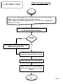
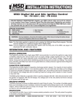
L-134 Static Timing
START
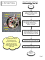
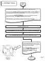
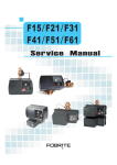
"Timing" the L-134 is frequently an issue.
More often than not, it is because the
flywheel and/or oil pump have been
installed incorrectly (see "Technical
Details", page 16).
When installed incorrectly, the "factory"
procedures/instructions for timing are
INVALID. Not to worry, the engine can
still be "timed", and will run fine. This
document will get you through the
process.
The procedures here are independent of
each other, but must be done in the order
shown. ie., skip over those you're
already familiar with, or have already
accomplished.
Install the
Distributor
(page 2)
Adjust Breaker
Point Gap
(page 3)
Set Breaker
Point Timing
(page 4)
The first three are relatively simple. Only
the "Spark Plug Wires" step requires
much mental effort or manual dexterity.
Additional descriptions/explanations are
at the end of the document, referenced
from w/in the flow charts.
Route the Spark
Plug Wires
(page 10)
start your engine !
FINISH
Page 1
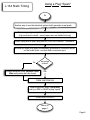
L-134 Static Timing
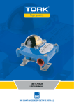
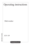
Install the distributor
IN
The end of the oil pump shaft has an
offset slot. The end of the distributor
shaft has an offset tab to match the oil
pump offset slot.
Look down the distributor hole. Note
the position of the oil pump offset slot.
Remove the distributor cap.
Hold the distributor so the offset tab is
aligned approximately the same as the
oil pump slot.
Install the distributor in the block. Turn
the distributor shaft slightly back-andforth until the offset tab drops into the
oil pump slot.
Crankshaft position is
IRRELEVANT for this
step. The distributor will
ONLY fit in ONE WAY.
(see "Technical Details"
page 16)
Seat the distributor body flush to the
block mating surface.
Return to
page 1
Page 2
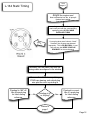
L-134 Static Timing
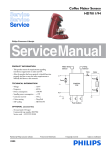
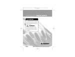
Adjust breaker point gap
IN
If they're not already, remove
distributor cap & rotor, loosen
distributor clamp
Rotate distributor body approximately
to the orientation shown at left:
Cap clips @ 3 & 9 o'clock
Oiler @ 1-2 o'clock
Further rotate distributor body until
points rubbing block is on highest
corner of closest breaker cam lobe.
This page applies ONLY to
OEM distributors with
mechanical breaker points.
If you have an "electronic"
distributor (Pertronix Ignitor,
Crown distributor, etc.) SKIP
THIS PAGE
Snug hold-down clamp finger tight.
Adjust breaker point gap to .020"
Return to
page 1
Page 3
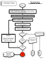
L-134 Static Timing
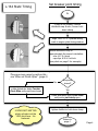
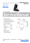
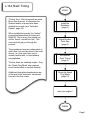
Set breaker point timing
IN
If they're not already, remove
distributor cap & rotor, loosen holddown clamp
Align "IGN" or "5º" flywheel timing
mark in engine plate timing window
Rotate distributor body to
approximately the correct orientation:
oiler @ 1-2 o'clock
cap clips @ 3 & 9 o'clock
(see photo on page 3 for example)
There are many ways to perform this see "When do Points Open" (page 5)
No
rotate distrubutor body Counter
Clock Wise until points are closed
are points
closed?
Yes
rotate distributor body Clock Wise
until points just barely open.
It DOES NOT MATTER
which cylinder is at the
"IGN" point here. It is
irrelevant.
tighten distributor hold-down clamp
Return to
page 1
Page 4
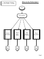
When do the Points Open?
L-134 Static Timing
IN
Pick a method
Using an
Ohm Meter
Using a
Feeler
Gauge
Using
Breaker
Points Arc
Using a
Plug Spark
go to
page
6
go to
page
7
go to
page
8
go to
page
9
Page 5
Using an Ohm Meter
L-134 Static Timing
IN
Use an ohm meter, either on the lowest "ohms" scale, or the "continuity" setting.
A meter with an "audible" continuity alarm works best. Use leads w/alligator clips
if you have them.
TURN IGNITION OFF!
(or disconnect cable from battery)
Disconnect the condenser
(if it won't change the point gap)
Clip one meter lead to the distributor input terminal
Clip the other meter lead to to distributor body (bare metal)
No
Rotate distributor body Counter Clock
Wise until meter reads ZERO ohms, or
"audible" signal sounds off.
meter
reading
ZERO?
Yes
Rotate distributor body Clock Wise
until meter just reads INFINITE ohms,
or "audible" signal goes silent.
Return to
page 4
Page 6
Using a Feeler Gauge
L-134 Static Timing
IN
Use a very thin feeler gauge: .001, .002, .003" max. If you don't have feeler
gauges, use a narrow strip of very thin plastic or paper
(cheapo "generic" sandwich baggies are only .001-.002" thick. Cigarette pack
wrap is also very thin)
TURN IGNITION OFF!
(or disconnect cable from battery)
No
Rotate distributor body Counter Clock
Wise until points fully close
are points
closed?
Yes
Manually open breaker points, and
insert feeler gauge between contacts
Apply slight pull on the feeler gauge
Rotate distributor body Clock Wise
until feeler gauge just slips out under
tension
Return to
page 4
Page 7
Using Breaker "Arc"
L-134 Static Timing
IN
In the absense of ohm meter & feeler gauge, you can use the electrical system
itself. You look and/or listen for an "arc" w/in the breaker contacts
Disconnect the condenser
(if it won't change the point gap)
Ensure a good ground path from distributor body to engine block
(if grounds are in doubt - use a jumper wire from distributor body to
a known good ground, or battery negative terminal)
are points
closed?
No
Rotate distributor body Counter Clock
Wise until points are fully closed
Yes
TURN IGNITION ON!
Rotate distributor body Clock Wise
until you SEE or HEAR the points "arc"
TURN IGNITION OFF!
reconnect condenser
Return to
page 4
Page 8
Using a Plug "Spark"
L-134 Static Timing
IN
Another way to use the electrical system itself: generate a real spark
Ensure a good ground path from distributor body to engine block
(if grounds are in doubt - use a jumper wire on distributor body)
Insert a plug wire & spark plug into the COIL SECONDARY TERMINAL
Ensure the spark plug body is adequately grounded to conductive metal
on the head, block, or some other convenient spot.
are points
closed?
No
Rotate distributor body Counter Clock
Wise until points are fully closed
Yes
TURN IGNITION ON!
Rotate distributor body Clock Wise
until you SEE or HEAR a plug "spark"
TURN IGNITION OFF!
Return to
page 4
Page 9
Route spark plug wires
L-134 Static Timing
IN
See
"Who Needs This"
(page 17)
Pick a method
"Quick & Easy"
"Get it right the
first time"
go to
page
11
go to
page
13
Page 10
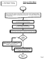
Run plug wires
L-134 Static Timing
("Quick & Easy" method)
IN
k
oc
st
install rotor, distributor cap &
spark plug wires. Begin with ANY
distributor cap post, as long as
firing order is correct:
1-3-4-2 Counter Clock Wise
eg.
does it
start?
re-clock plug
wires 90º CCW
SUCCESS!
No
No
tried it 4
times?
Yes
Other issues
need resolved
before timing
Yes
go to
page
12
FAILED!
Page 11
from
page 11
L-134 Static Timing
Alright! the engine runs!
Now to determine how the oil pump &
flywheel are installed:
Draw a diagram of the distributor cap, and
mark each post with the corresponding
spark plug wire, AS YOU HAVE
INSTALLED THEM!
stock
If your plug wires aren't close to "stock"
locations, the oil pump was indexed
improperly. This is NO BIG DEAL, it runs
fine any way, but KEEP YOUR CAP
DRAWING for future reference.
Manually turn the crank over until the
timing marks are aligned in the window
Remove the distributor cap. Using
YOUR cap drawing, note which plug
wire post the rotor is pointing at
Flywheel is 180º off.
Use #2 spark plug
for future timing
reference.
No
pointing at #1
or #4 plug?
Yes
Flywheel is correct.
Use #1 spark plug
for future timing
reference.
Return to
page 1
Page 12
Run plug wires
L-134 Static Timing
("Right the 1st time" method)
Begin
Remove distributor cap, Install rotor
Remove #1 spark plug (or ALL plugs for easiest cranking)
Set both throttle & choke WIDE OPEN
rotate crankshaft until TDC flywheel mark is lined up
MAKE A DRAWING OF ROTOR POSITION!
put thumb or finger over
#1 spark plug hole
quickly turn crankshaft about 90º
clockwise (viewed from front)
feel
suction
?
Discard any previous rotor
drawing !
Yes
Flywheel correct!
No
Rotate the crankshaft the
remaining 270º until TDC
marks line up again.
feel
pressure
?
Yes
Flywheel wrong
(180º off)
No
No
tried
twice
?
Yes
Other issues
need to be
resolved first
FAILED!
go to
page
15
go to
page
14
Page 13
L-134 Static Timing
from
page 13
You arrived here because you felt suction at the #1 spark plug hole.
That means #1 cylinder is ON the Power stroke, and has just gone past
TDC on the Compression stroke.
You had previously MADE A DRAWING of where the distributor rotor was
pointing at the time. Now MAKE A NOTE on that drawing:
That distributor cap location is where #1 spark plug wire goes!
Install the distributor cap
Put #1 plug wire in the POST POINTED AT BY YOUR ROTOR DRAWING
Install the remaining plug wires 3-4-2 order Counter Clock Wise.
If your plug wires aren't close to "stock"
locations, the oil pump was not indexed
"according to the manual".
ck
sto
This is NO BIG DEAL, it runs fine any
way, but KEEP A DRAWING OF
YOUR CAP & WIRES for future
reference.
Return to
page 1
Page 14
L-134 Static Timing
from
page 13
You arrived here because you felt pressure at the #1 spark plug hole.
That means #1 cylinder is ON the Compression stroke, and #2 cylinder has
just gone past its own TDC compression (and is now on it's power stroke)
You had previously MADE A DRAWING of where the distributor rotor was
pointing at the time. Now MAKE A NOTE on that drawing:
That distributor cap location is where #2 spark plug wire goes!
Install the distributor cap
Put #2 plug wire in the POST POINTED AT BY YOUR ROTOR DRAWING
Install the remaining plug wires 1-3-4 order Counter Clock Wise.
If your plug wires aren't close to "stock"
locations, the oil pump was not indexed
"according to the manual".
sto
ck
This is NO BIG DEAL, it runs fine any
way, but KEEP A DRAWING OF
YOUR CAP & WIRES for future
reference.
Return to
page 1
Page 15
L-134 Static Timing
Technical Details
Unlike contemporary engines, the L-134 has two mechanical idiosyncracies that can cause
confusion if parts are not installed "according to the manual" during engine rebuild or parts
replacement.
The timing marks are on the FLYWHEEL (not the front pully as on most modern engines), so
flywheel mounting determines which cylinder can be used with a timing light.
The flywheel can be mounted to the crankshaft in 2 opposite orientations:
1) Correctly (according to "factory" procedure) - In this case, the "TDC" timing marks apply to
#1 & #4 cylinders as per the "factory manual".
2) Incorrectly (NOT according to "factory" procedure) - In this case, the "TDC" timing marks
apply to #2 & #3 cylinders.
The oil pump drives the DISTRIBUTOR (in many modern engines it's the opposite: the
distributor drives the oil pump).
The oil pump gear has 12 teeth, so it can mesh with the camshaft gear in ANY ONE of 12
positions. But due to an offset slot, the distributor ONLY FITS THE OIL PUMP ONE WAY!
When the oil pump is installed according to "factory" procedure, the #1 spark plug wire fits the
distributor cap at about the 5 o'clock position.
When the oil pump is installed WITHOUT regard to the "factory" procedure, then the #1 spark plug
wire can end up at ANY ONE OF THE OTHER 11 "WRONG" POSITIONS!
NEITHER OF THE ABOVE prevents the engine from running. If either flywheel or oil pump is
installed off-spec, it simply means you CANNOT use the written procedures in the "factory"
service manuals.
You just have to determine how your engine assembly differs from "factory standard", make a note
of the difference, and keep it for future reference.
Page 16
L-134 Static Timing
Who Needs This ?
This document is intended for those situations when the flywheel and/or oil pump installation are
UNKNOWN, SUSPECT or KNOWN TO BE WRONG.
If you KNOW FOR A FACT that your flywheel is been installed correctly, and your oil pump
has been indexed correctly, this document is not needed. Just run your plug wires according to
the service manual illustrations (#1 wire at 4-5 o'clock position, 1-3-4-2 CCW firing order).
If you KNOW or SUSPECT that either flywheel or oil pump are NOT correct, you have 2 choices:
! re-install them per the "factory" manual (labor intesive, and NOT necessary), or ...
! live with them as-is, just "do what it takes to get the engine running"
There are 2 ways to "do what it takes to get the engine running":
1) The "quick & easy" way: FIRST get it running, THEN figure out the "details":
This is a "Trial-and-Error" approach. The plug wires can only be installed 4 possible ways.
ONE of them WILL be correct. You just have to try each possible orientation, in turn, until you
hit upon the "correct" one.
You run the risk of having it wrong to begin with, and getting backfire, but ...
You DO NOT NEED TO KNOW:
! if the flywheel is on right or wrong
! if the oil pump has been indexed correctly
! what cylinder is "on the compression stroke"
2) the "get it right the first time" way: FIRST figure out the "details", THEN get it running
The "Get It Right The First Time" way is a methodical approach. It takes more time, but there's
no "trial-and-error" involved, it is "right on" the first time.
You WILL first determine which cylinder is on a compression or power stroke
After using either method above, you'll have all the answers to the "Flywheel", "Oil Pump" and
"Spark Plug Wiring" questions.
Page 17