1
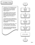
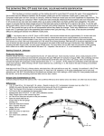
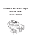
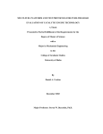
Installation Guideforthe Electronic Ignition Distributor Remanufactured By East Coast Roadster East Coast Roadster: Ignition systems and accessories for Datsun Roadster fanatics! (336)624‐5083 www.EastCoastRoadster.com Copyright East Coast Roadster 2010-2011 ELECTRONIC IGNITION DISTRIBUTOR INSTALLATION GUIDE FOR THE 1600/2000 DATSUN ROADSTERS 2. Support: Tom Lorick: [email protected] Contents A. B. C. D. E. F. G. H. I. J. K. 3. Introduction Tools Required How the EI Distributor Works Removal of Your Original Roadster Distributor Installation of the EI Distributor Wiring Connections Engine Startup and Timing Adjustment Other Ignition System Components Replacement Parts Troubleshooting Correct Installation of Distributor Drive Gear 4. A. Introduction NOTE: Please read and follow the detailed instructions in this guide, at a minimum don’t overlook the following items: 1. You must install a 12 volt coil (see details about acceptable coil winding resistances below) 2. Bypass or remove the ballast resistor (if you remove it, connect the 2 wires and insulate) 3. Open the spark plug gaps to 0.039” to 0.043” 4. Set the ignition timing (it’ll be the last time you have to do this, unless you remove the distributor in the future). Timing specifications are below. With this upgrade, there will never be a need to adjust or replace points again. High engine rpm performance will improve because points bounce will be non-existent. After setting the timing, it remains unchanged. It’s a completely self-contained distributor with a simple 2 wire hook-up to the coil. This distributor is built to produce 15 of centrifugal advance at the crankshaft, which is identical to the non-smog roadster distributors (pre-1968). Compared to the distributors for emissions equipped roadsters, the non-smog advance makes a roadster engine run much better and helps prevent overheating problems. Also included at the end of this guide is a troubleshooting section for the electrical components of the EI distributor. Copyright East Coast Roadster 2010-2011 Page |2 Remove the distributor and the pedestal from the engine. If the gear is properly installed, the slot in the top of the drive gear shaft is nearly perpendicular to the engine block, but more exact, like a 12:15 o’clock position on the top and 6:15 o’clock position on the bottom. If it’s not, remove the gear using long needle nose pliers. The gear will rotate as it comes out due to the helical gear teeth. Notice that the slot in the top of the gear is offset from the center of the shaft. The Nissan Service Manual contradicts itself whether the slot is to be offset to the front or rear, but it’s not critical which way it is. Now comes the possible frustration. Install the gear by starting it rotated several degrees from the perpendicular angle, so that as it slides into place, the helical gear will rotate the gear into the perpendicular angle when it seats. The tricky part is getting the tang on the bottom of the shaft to engage with the slot in the top of the oil pump as it drops into the hole. You’ll likely need to adjust the orientation of the oil pump slot with a screwdriver so the drive gear tang will engage it. This requires some trial and error to have it engage the slot and get the correct perpendicular angle when fully seated, both at the same time. The distributor pedestal will not fully drop into place if the gear did not engage the oil pump slot. IMPORTANT: Do not try to force the pedestal into place, it should drop in with no resistance!! 5. 6. 7. If you are unsuccessful after a couple of attempts, and you think you have it close but the gear has not engaged the oil pump slot, roll the crankshaft back and forth a little and this will help the gear drop into the oil pump slot. Be aware that the gear will rotate a little more when the tang engages the oil pump. Reinstall the distributor pedestal and reconnect the oil line and tachometer drive cable to it. Verify that the orientation of the tang on the distributor drive coupling has the matching orientation with the slot in the drive gear. The tang on the distributor drive coupling is offset from center. With the distributor rotor pointing toward #1 spark plug wire on the distributor cap, verify the offsets match between the distributor drive coupling and the slot in the top of the distributor drive gear you just re-installed. Reinstall the distributor. 15 | P a g e Copyright East Coast Roadster 2010 -2011 IMPORTANT NOTE: A 12 volt coil must be installed. The factory Nissan coil from cars with this distributor is recommended. The Nissan part # is 22433-P7500. An option is to buy a new aftermarket coil from your auto parts store, which should be specified for a 1980 Nissan 210 (any of 3 engine size options). The coils from an auto parts store may not come with a mounting bracket and some 12 volt coils are larger in diameter than the original roadster coil, and likely will not fit the original mounting bracket. The high performance aftermarket coils to consider include the MSD Blaster 2 coil (MSD 8202, without external resistor) and the Crane PS60. New spark plug wires are strongly recommended, unless yours are in very good condition, as the voltages they will now be carrying are much higher than stock. B. Tools Required 1. 2. 3. Timing Light (not absolutely required) 8 mm wrench 10 mm wrench (for metric engines), TBD for SAE engines C. How the EI Distributor Works With the original roadster distributor, the ignition trigger is supplied by the breaker points as the contacts open and close. With the EI distributor, it is instead, provided by the reluctor (on the rotor shaft) and the pick-up coil. As the reluctor rotates, the magnetic flux passing through the pick-up coil changes. The changing magnetic flux generates an electrical signal in the pick-up coil. This electrical signal is sent to the IC ignition module (mounted on the side of the distributor), which triggers the primary current running through the ignition coil. This generates high voltage in the secondary winding of the coil, which is distributed to the spark plugs. K. Instructions for correct Re-installation of distributor drive gear, if needed 1. Set the crankshaft orientation at 0 TDC between compression and power strokes for cylinder #1, by lining up the big notch in the crank pulley with the pointer on the timing cover. Verify that it’s between compression and power strokes either by checking that the distributor rotor is pointing toward #1 spark plug wire on the distributor cap, or that both valves on cylinder #1 are closed. When the valves are closed on a U20, both cam lobes for #1 cylinder are pointing upward. On a R16, the rocker arms are high (relative to other valves that are open) on the valve end of the rocker arm. If the valves are not closed, you need to rotate the crankshaft one full turn. Copyright East Coast Roadster 2010-2011 P a g e | 14 The IC ignition module (attached to the side of the distributor housing) performs multiple functions with 5 individual circuits: 1. Spark timing signal monitoring circuit – This circuit detects the ignition signal sent from the distributor pick-up coil, and amplifies the signal. 2. Lock-preventing circuit – This circuit cuts off the ignition coil primary current when the ignition switch is ON and the engine is stationary. If the ignition coil primary current is allowed to flow under such conditions, excessive current will be drawn because of low internal resistance of the ignition coil. This can result in an abnormal temperature rise in the ignition coil or a discharged battery. These malfunctions are prevented by this lock-preventing circuit. 3. Duty control circuit – This circuit controls the ratio of the ignition coil primary current ON-OFF time periods, in one cycle of ignition 3|Page Copyright East Coast Roadster 2010 -2011 4. 5. operation. This is equivalent to the dwell angle of the conventional point type distributor. In order to provide high performance spark firing over a wide range of driving speeds, this duty can be controlled by the source voltage and the ambient temperature, as well as by the engine rpm. Power switching circuit – This circuit is used to make or break directly the primary circuit current of the ignition coil. Current limiting circuit – This circuit controls the current value so that excessive current will not flow through the power switching circuit. D. Removal of Your Original Roadster Distributor If you are familiar with replacing distributors, much of the following procedure can be skipped. The basics rules apply to installing this distributor, just like an original roadster distributor, except for wiring. You may want to take pictures for reference and posterity! 1. 2. 3. WARNING: Disconnect the battery! If your distributor is already removed, skip down to step 2. Otherwise, disconnect the wire and vacuum hose from the old distributor. Remove the distributor cap and make a mark on the cap and aluminum housing to show the direction the rotor is pointing. Determine which cylinder’s spark plug terminal the rotor is pointing toward by tracing the spark plug cable to the corresponding cylinder. You do not need to worry about getting it lined up with the #1 cylinder. Remove the single bolt holding down the distributor and slide the old distributor out. If your old distributor was not already removed, skip to the next section. Manually roll the crankshaft clockwise (as viewed from the front) to orient the crankshaft so that the #1 piston is at TDC (top dead center) at the top of the compression stroke. It’s easier to roll the crank manually by removing the spark plugs first. Make sure the transmission is in neutral with the emergency brake engaged. If it’s too difficult to roll by hand, use a socket (27 mm for 67.5 and later) and ratchet on the crank pulley bolt. Turn the crank so that the 0 degree timing mark on the crank pulley lines up with the pointer on the timing cover. Verify the crank is positioned with #1 piston at TDC on its compression stroke by determining that both valves on #1 cylinder are closed. On the U20 engines, both cam lobes for #1cylinder are pointing upwards. For the R16 engines, the valve end of the 2 rocker arms for cylinder #1 should be in the up position to indicate the valves are closed. If the 2 valves are not closed, you must rotate the engine one full turn and set it at 0 degrees TDC. This step will ensure later that the converted distributor is installed in the correct Copyright East Coast Roadster 2010-2011 Page |4 Troubleshooting the entire ignition system is beyond the scope of these installation instructions. However, if your distributor is not producing current to the coil, the following is a guide for checking the electrical components of the EI distributor. Before troubleshooting the distributor, verify that the distributor is receiving power from the ignition switch. 1. 2. 3. Turn the ignition switch to the “OFF” position. Remove the distributor cap. With a circuit tester, measure the resistance between the 2 terminals of the pick-up coil as a distributor assembly. The 2 terminals are found in the rubber grommet on the top edge of the distributor housing adjacent to the IC ignition module. Measure the resistance by reversing polarity of the circuit tester probes. 4. If the resistance is approximately 400, the pick-up coil is good and the IC ignition module is possibly bad. Many auto parts stores can test the module. If the resistance is not approximately 400, proceed to step 5. 5. Verify that the wiring harness is connected to the IC ignition module. 6. Turn the ignition switch to the “ON” position. 7. Measure the voltage at the ignition coil (-) terminal. 8. Turn the ignition key to the “OFF” position. 9. If voltage measured in step 7 is 0, the IC ignition module is possibly bad. If voltage is approximately 12V, proceed to step 10. 10. Unplug the red and green wires from the IC ignition module. Measure the resistance between the 2 terminals of the pick-up coil (red and green wires). 11. If the resistance is approximately 400, the pick-up coil is good and the IC ignition module is possibly bad. If the resistance is not approximately 400, the pick-up coil is bad. 12. If no spark occurs after replacing the pick-up coil and checking all other components of the ignition system, replace the IC ignition module. 13 | P a g e Copyright East Coast Roadster 2010 -2011 orientation for proper ignition timing, or at least close. Disconnect the wire and vacuum line to the distributor. DO NOT remove the cast iron distributor pedestal from the block. Remove the single screw in the distributor fixing plate. Remove the distributor. Regap your spark plugs to 0.039” to 0.043” while they’re out. Reinstall the spark plugs, Put dielectric grease in the boots attach the spark plug cables, and leave the cables connected to the distributor cap. X E. Installation of EI Distributor 1. X X X X X X X Burned, cracked, or improperly seated rotor X Distributor installed with missing or bad O-ring X Vacuum hoses leaking or disconnected X Spark advance system faulty X Plug wires defective or connected in wrong firing order X Moisture in distributor Distributor control wiring loose or corroded X Ignition timing incorrect Distributor drive coupling installed backward Engine will not start Engine backfires but does not start Engine runs rough or misfires at high speed Excessive fuel consumption Intermittent operation Oil leak under distributor Engine detonates (pings) Distributor not properly seated SYMPTOM Loose, cracked, or defective distributor cap Troubleshooting POSSIBLE CAUSE & SOLUTION J. X X X 2. X X 3. X X X 4. X Copyright East Coast Roadster 2010-2011 P a g e | 12 Since it is impossible to know how every roadster distributor drive gear is installed (the Nissan manual contradicts itself between its photo and its text instructions for installing the drive gear), it will be necessary to install the drive coupling (the wobbly piece on the end of the lower distributor shaft) with the orientation of your drive gear slot. Install the coupling with the correct orientation of the offset tang as follows: Hold the distributors side by side with the fixing plate pointer in the same orientation for both distributors. Point the rotor on your original distributor toward the same direction it was in before you pulled it out. Then point the rotor on the EI distributor in the same direction as for the original one, making sure the fixing plate pointers on both distributors are in the same orientation. Install the drive coupling on the end of the distributor shaft so that the offset tang is oriented the same as on the old distributor. Slide the pin into the drive coupling and shaft. Slide the spring over the pin to hold the pin in place. Verify that the orientation of the tang on the drive coupling is such that it will engage the offset slot on the drive gear in the engine while holding the distributor housing with the fixing plate pointer facing away from the engine NOTE: The O-ring may have remained in the groove of the distributor pedestal, if so, remove it. A new one is supplied. You should grease it or oil it, it’s a tight fit. Slide the new EI distributor into the engine. You may need to rotate the rotor shaft a few degrees either direction for the drive coupling tang to engage with the drive gear in the engine block. After the distributor is seated on the pedestal, rotate the distributor so that the pointer on the fixing plate is centered at the 0 mark on the pedestal. You may need to clean the top surface of the pedestal to see the marks (use a wire brush or fine sandpaper if necessary). Tighten the screw on the fixing plate to the pedestal. If the screw is not hex head, you will need to replace it with a hex head screw. The reason a hex head screw is not provided is because the early engines have a SAE threaded hole and the late engines have a metric hole. Through the course of the years, your pedestal could be either metric or SAE since they do interchange and may have 5|Page Copyright East Coast Roadster 2010 -2011 5. 6. 7. been swapped. Loosen the screw (8mm hex head) under the fixing plate to adjust the timing initially. The ignition timing can be set before starting the engine if a timing light is not available. First, roll the engine crank manually (it’s easier to roll with spark plugs removed) so that the timing mark on the crank pulley is set at 16 BTDC for SU’s or 20 BTDC for Solex’s. You need to have the crank positioned so that #1 cylinder is at the end of the compression stroke, so the rotor should be pointing toward the #1 spark plug terminal on the cap. If you wish to verify, you can do so by determining that both valves on cylinder #1 are closed. If the valves are open, you need to roll the crank one more full revolution. Now rotate the distributor housing so that the tips on the reluctor (“Star”) line up with the tips on the stator (Fixed metal tips). After the ignition timing is set, tighten the 8 mm hex screw underneath the fixing plate. Any further adjustment can be made with the screw on top of the fixing plate. With the EI distributor’s cap installed, transfer the spark plug cables to the EI distributor cap, by starting with the spark plug cable for the cylinder # that the rotor was facing (#1 if you had set #1 cylinder at TDC). You may wish to put a bit of dielectric grease on the terminals. Attach the remainder of the spark plug cables according to how they are attached to the original cap. If the arrangement is uncertain, you can determine the proper arrangement by the firing order. If you are certain that the #1 cable (or the cylinder # the rotor was facing) is in its correct terminal on the cap, attach the other cables in the firing order of 1-3-4-2 in a counter-clockwise rotation, as the distributor rotates counterclockwise. F. Wiring Connections 1 2 3 4 Refer to the wiring schematics at the end of this section, if necessary. Connect the new wiring harness plug to the ignition module on the side of the distributor, a bit of dielectric compound on the connections prevents corrosion. You can use the bend tab on the module screw to secure the harness. The wire(s) originally connected to the (+) terminal of the coil will need to reconnected to the (+) terminal of the 12 volt coil that you will install. The wire connected between the original distributor and the (-) terminal of the coil can be removed and saved in case you ever decide to re-install a stock distributor. In some cases, this wire is bundled in the harness, so you can just disconnect it and secure it out of the way however you choose. Copyright East Coast Roadster 2010-2011 Page |6 Verify a used coil is good by checking the resistance across the windings of the disconnected coil. Primary winding resistance should be 0.84 to 1.02 ohms. (Measured between the two small terminals on the coil.) Secondary winding resistance should be 8.2 to 12.4 kilo-ohms. (Measured between the large center contact and either of the two small terminals). Sparkplugs: NGK BP6ES-11 (or BPR6ES-11 to limit radio interference). Original stock spark plugs will work fine but need to be re-gapped to 0.039” to 0.43 Sparkplug Gap: Increase the spark plug gap as there is now a stronger spark. The increase in spark plug gap depends on the rest of your ignition system. Standard Upgrade: If the converted distributor and the 12-volt coil (with ballast resistor bypassed or removed) are the only ignition system modifications, the new recommendation for the spark plug gap is 0.039” to 0.043”. MSD Ignition: If you have an MSD or other capacitive discharge high-energy system, 0.045” to 0.050” seems to work well. Sparkplug Wires: To realize the full potential of the new distributor use good quality spark plug wires. I. Common Replacement Parts Grommet, Nissan Part # 22153-S6701 Reluctor, Nissan Part # 22115-H9100, Napa Auto Parts ECH MP409 Stator, Nissan Part # 22163-H9100 Magnet Assembly, Nissan Part # 22158-S6700 Pickup coil, Nissan Part #22229-H9100, Napa Auto Parts ECH MP405 O-ring between fixing plate and pedestal 22180-71200 Vacuum controller, Nissan part # 22301-N4700 or Napa Auto Parts ECH VC4044 Cap & Rotor, most auto parts stores, for 1982 Nissan 210 1.4 L engine Ignition Module – E12-80, very reliable but expensive new – advise searching salvage yard for one from a 1979-82 Datsun 210, 310, 510, 810, 280ZX, or pickup. Have it tested and carry it in your glove box 11 | P a g e Copyright East Coast Roadster 2010 -2011 5 6 G. Engine Startup and Timing Adjustment 1. 2. 3. Set spark plug gap to 0.039” to 0.043. Nissan calls for the idle ignition timing (at 700 rpm) to be at 16 BTDC for SU 1600’s and 2000’s and 20BTDC for Solex U20 engines. Note: This should be checked with the vacuum hose disconnected from the vacuum controller on the distributor. On the crank pulley, the big timing mark groove is 0 degrees TDC and the mark on the opposite end is 20 degrees BTDC. After full engine warm-up, check for desired idle timing. ALWAYS wear eye protection when checking the timing on a running engine and keep hands and loose clothing away from any spinning parts. When using a timing light, the idle speed must be at 800 rpm or less. If the engine speed is above 800 rpm while setting the idle speed timing, the distributor’s internal advance mechanism has already started to advance and the distributor will not be set to reach the full advance under load. If you are unable to get the timing set in an acceptable range, after rotating the distributor housing through its full rotation in the slots in the fixing plate, the distributor drive gear in the engine block is probably off by a tooth or 2. See instructions at the end of this document regarding correcting this problem. If using a vacuum advance, re-connect the vacuum hose from the carburetor to the vacuum controller on the distributor. If you need new vacuum hose, it’s 3/16” and available at your local auto parts store. NOTE: The engine’s vacuum source to the distributor MUST be from the vacuum fittings on the carburetor(s), NOT from a fitting on the intake manifold. (Not applicable to SOLEX equipped cars). Drive the car and ensure that, under load, that there is no engine pinging. If so, retard the timing (Less advance timing i.e. - from 16° to 12°) enough to prevent pinging. IMPORTANT NOTE: Extended driving with engine pinging will cause major engine damage. 7 Install the 12-volt coil. Connect the wires of the new harness from the ignition module to the 12-volt ignition coil according the tags on the wires. The Red wire connects to the (+) terminal of the coil along with the wire from the ignition switch (see step 2 above). The black wire connects to the negative (-) terminal of the coil. Don’t forget to connect the wire that comes from the ignition switch (via the ballast resistor) to the (+) terminal of the 12 volt coil. If you have any other devices getting power from the (+) terminal, such as an electronic tachometer, they should be re-connected to the (+) terminal of the 12 volt coil. Because there are no longer any ignition points to protect and because the EI distributor is designed to operate on 12 volts, the ballast resistor can removed. The ballast resistor is a ceramic box, which is mounted just below the coil, it has a wire connected at each end. Install the provided jumper wire (the short red wire) to each end of the resistor to bypass it. To install the jumper wire, loosen the nuts on each end of the resistor just enough to slide the bypass wire connectors under the nuts. Or remove the ballast resistor and connect the two wires from each end of the resistor together (secure and insulate them so they don't touch any grounded surface). An easy option is to cut off the connectors and connect them with a butt splice. If you ever re-install a points distributor or a Pertronix Ignitor (which may not handle 12 volts like this EI can), be sure to remove the bypass wire or re-install the ballast resistor as it was originally set up. H. Other Ignition System Components Coil: You must use a 12-volt ignition coil designed for EI. It produces a stronger spark than the roadster’s original 6 volt coil. The original Roadster coil is designed to work with a ballast resistor. Use of the 12V EI distributor and without the ballast resistor will overheat and/or burn out the original roadster coil. New Coil: Nissan coil for the 12V EI is part # 22433- P7500. Used Coil: 1979-82 Datsun 210, 310, 510, 280ZX, or pickup truck, you should also get the mounting bracket. Copyright East Coast Roadster 2010-2011 P a g e | 10 7|Page Copyright East Coast Roadster 2010 -2011 Copyright East Coast Roadster 2010-2011 Page |8 9|Page Copyright East Coast Roadster 2010 -2011