1
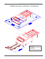
1000 P / 2000 P / 3000 P
Pre Installation Manual
DuPont - Cyrel
®
Cyrel ® 1000 P / 2000 P / 3000 P
Pre Installation MANUAL
(subject to technical changes)
1000 P / 2000 P / 3000 P (04/02)
1000 P / 2000 P / 3000 P
Pre Installation Manual
Page
Contents
1. About the machine
Page
1.1
Address of manufacturer
Service Manual
4
1.2
Type of equipment
Service Manual
4
1.3
Description of operation
Service Manual
5
1.4
Description of the process
Service Manual
6
1.5
Designation of jobs
Service Manual
6
1.6
Data on noise emissions
4
1.7
Information on ventilation and fumes
4
1.8
Electrical fittings
Service Manual
7
1.9
Information specific to machinery materials
Service Manual
7
2. Transporting and setting up the machine
2.1
Unloading
5
2.2
Transporting
5
2.3
Setting up and aligning
5
2.4
Foundations
5
3. Bringing the machine into service
3.1
Requirements for fixing and anchoring
6
3.2
Conditions for installation
6
3.3
Space requirement for operation, servicing and maintenance
6
3.4
Permissible ambient conditions
6
...3.5
Connecting to the power supply,
preparation for putting into operation, first filling
7
3.6
Principles for putting into service
Service Manual
11
3.7
Checking for correct operation
Service Manual
11/12
3.8
Requirements for use in a potentially
Service Manual
12
explosive atmosphere
4. Safety
4.1
Safety measures when working at the machine
Service Manual
13
4.2
Notes on the use of personal protective equipment
Service Manual
13
4.3
Information on residue risks, avoiding hazards
Service Manual
13
4.4
Environmental protection
Service Manual
13
Pre Installation Manual English 1000 P / 2000 P / 3000 P
2
1000 P / 2000 P / 3000 P
Pre Installation Manual
Page
5. Information on the operation on the machine
5.1
Description of the functions of all individual components
Service Manual
14-16
5.2
Measuring solid matter content and solvent heating
Service Manual
17
5.3
Description of adjustment and replacement work
Adjustments
3
5.4
Basic information about the washing brushes
Adjustments
4-7
5.5
Improper usage
Service Manual
17
5.6
Instructions for recognizing and eliminating errors
Service Manual
18
6. Operation
6.1
Starting the machine
Service Manual
19
6.2
The operations field
Service Manual
19-27
6.3
Manually filling the internal tank
Service Manual
28
6.4
Plate production
Service Manual
29
6.5
“Drum-to-drum” operation
Service Manual
30
6.6
“Tank-to-tank” operation (with distillation)
Service Manual
30
7. Instructions for equipment maintenance
7.1
Type and frequency of inspections (operator)
Service Manual
31
7.2
Instructions for maintenance work
Service Manual
31
7.3
Type and frequency of maintenance work (service) Service Manual
7.4
Address of DuPont
32
Service Manual
33
8. Safety-related information for removing the machine
from service and dismantling
Service Manual
33
9. Information for emergency situations
9.1
Type of fire extinguishing equipment to be used
Service Manual
34
9.2
Notes for rescue
Service Manual
34
10. Technical data and plans
Delivery list
8
Loading plan / Pre-loading plan
9/10
Set-up plan, space requirements – transport plan
11
Specifications, technical data
12
Flow plan / Liquid conduits and switching points
for the level gauges
Service Manual
40
Pneumatics plan
Service Manual
41
Electrical wiring plan
Service Manual
42-55
Pre Installation Manual English 1000 P / 2000 P / 3000 P
3
1000 P / 2000 P / 3000 P
Pre Installation Manual
Page
1. About the machine
1.6 Data on noise emissions
Noise emissions < 70 db(A)
1.7 Information on ventilation and fumes
Permissible workplace concentrations:
- Perchlorethylene: 50 ppm (MAK)
- FLEXOSOL: 300 ppm (OEL)
Adequate ventilation of the production room must be provided.
Attention:
The room air must be ventilated out from floor level because the solvent fumes can be heavier
than air (depending on solvent, i.e. when using Per).
The cleaning solution poses a threat to the water supply and must not reach the sewage system
or get into the ground! A safety collection tank must be set up that can take up the entire
volume of solvent (standard equipment).
The floor of the production room must be even.
In addition, the floor must be sealed with a water-repellent coating that must also be resistant to
the solvent used.
Any available floor drainage must not be connected to the sewer system.
The machine’s suction ventilation is located at plate input and at plate output. The exhaust line for the
ventilator may not be longer than 10 m with a maximum of 2-3 / 90° bends
For exhaust lines more than 10 m in length, an additional blower must be added. This must create light
low pressure at the machine ventilation points. Performance at full operation is to be set to ca. 200 m³/h
with the aid of an adjustable damper.
Pre Installation Manual English 1000 P / 2000 P / 3000 P
4
1000 P / 2000 P / 3000 P
Pre Installation Manual
Page
2. Transporting and setting up the machine
The unloading as well as the transport of the machine may only be carried out by authorized
specialists. For this work, personal protective equipment i.e. safety shoes and leather gloves
are to be used!
2.1 Unloading
The machine is basically delivered on a palette (or packed for oversees shipping) and should be
unloaded from the truck complete with packing.
When unloading the machine from the palette, be sure to lift the machine only from the bottom of the
frame at the marked points and make sure no parts become damaged. The side and top sheet metal of
the machine must be removed first. The machine is anchored to the cross beams with 6 fastening bolts
(tool: socket wrench SW17). The output (only 2000 P and 3000 P) is secured with straps. These must
also be removed.
Lift the machine with a forklift (2.2 meter fork length) and screw in the feet. Here, clearance of 110 mm
must be maintained, as the safety tank (100 mm) must still be placed under the machine.
(cf. Set-up plan, space requirement – transport plan)
(cf. Loading plan)
(cf. Pre-loading plan)
2.2 Transporting
Unloading the machine at its final location should carried out with the appropriate means of transport,
carefully and without warping. At this point, transport paths, door widths and the swinging radius are to
be taken into account. (cf. Set-up plan, space requirement – transport plan)
Should space circumstances not allow transport of the complete machine, it is possible to dismantle the
output (cf. Set-up: assembly / dismantling instructions for the output). These tasks must be carried out
by trained personnel.
2.3 Setting up and aligning
When setting up the machine, there must be sufficient space between it and the walls and other
machines to allow for service and maintenance work. The distance should be about 1 m.
(cf. Set-up plan, space requirement – transport plan)
At the point of set-up, the machine is to be aligned precisely with a spirit-level. For this, the cover of the
washout area must be removed. The spirit-level is laid on the top edge of the tank and the machine is
aligned exactly with the aid of the adjustable feet.
For installation of the safety tank, a distance of 110 to 115 mm, floor – bottom edge of the frame, is to
be observed.
2.4 Foundation
A special foundation for the machine is not required. The load bearing capacity of the floor should be
1000 kg/m². The weight of the machine is taken from the specification tables.
Pre Installation Manual English 1000 P / 2000 P / 3000 P
5
1000 P / 2000 P / 3000 P
Pre Installation Manual
Page
3. Bringing the machine into service
3.1 Requirements for fixing and anchoring
The machine rests on it´s levelling feet; a special fixture is not required
3.2 Conditions for installation
The floor of the production room must be even.
Furthermore, the floor must be sealed with a water-repellent coating that must also be resistant to the
solvent used.
Any existing floor drainage systems must not connect to the waste water system.
3.3 Space requirements for operation, service and maintenance
Feeding and removing plates takes place at either end of the machine. In order to allow for service
work, there must be at least 1 m of free space surrounding the machine.
(cf. Set-up plan, space requirements – transport plan)
3.4 Permissible ambient conditions
The environment should be similar to that in an office.
Recommended room lighting: Lumilux Interna W 31 – OSRAM
Natural light UVA screened
Room temperature: 22°C
Relative humidity: ca.55%
Pre Installation Manual English 1000 P / 2000 P / 3000 P
6
1000 P / 2000 P / 3000 P
Pre Installation Manual
Page
3.5 Connecting to the power supply; Preparation for putting
into operation, first filling
Electrical connection
(recommendation)
Connect the machine through a wall switch or fuse switch.(lockable)
Follow connection terms of local power companies and all local codes.
Compressed air connection
dry, 6 bar / 200 l/min – via DIN, ½“ hose connection.
Machine ventilation
The ventilation line must correspond to the dia (100 mm) of the exhaust flange. It must be installed so
that the ventilation opening terminates well outdoors and outside of the workrooms. Continuing ducts
can consist of galvanized steel tubing or a suitable synthetic tubing.
Exhaust ducts appropriate for the machine ventilation volume (ca. 200 m³/h) should be installed.
Installing an adjustable damper is recommended.
Solvent supply connection
The standard version of the machine is suitable for “drum-to-drum” operation.
Here, fresh solvent appropriate for the size of the plate is supplied to the system from a drum. The
saturated dirty solvent is pumped off into an empty drum.
Delivery of the standard version of the machine contains one level switch each for the fresh and for the
used solvent drums (200 l). The level switches are to be put into the top side of the respective drums.
The longer level switch is used for the fresh solvent drum; the shorter one for the used solvent drum.
The switches will be labeled accordingly.
For connecting the line from drum to processor, connection points are provided on the back side of
the machine. The other ends of the line are to be fitted into the second opening on the top side of the
drums.
Attention
Be sure that the connecting lines are not longer than 10 m and that they lie in one plane. For security
reasons, the entire length of the line must be visible.
As material for the connecting tubes, gasoline- and oil-tight tubing will be used. (- independent of
solvent -)
As an alternative to this, sturdy tubing can also be used. This must be equipped with a flexible
connector at the corresponding drum side.
If the machine is operated with permanently installed tanks, special level switches are to be fitted for
the tanks.
(Ex- or intrinsically safe level gauge in Ex-Rooms)
Should installation circumstances differ, please consult with the manufacturer or seller
Pre Installation Manual English 1000 P / 2000 P / 3000 P
7
1000 P / 2000 P / 3000 P
Pre Installation Manual
Delivery list
No.: ......................
Pieces
Name
3
Safety drip tray
3
Transport bar
1
Cooling device
2
1
Synthetic hose NW 13 (1/2“) 0.6 + 0.8 m
for cooling device
Air hose ø 9mm, L= 3m
2
Filter screen
1
Float switch for fresh solvent drum
1
Float switch for old solvent drum
1
1
Synthetic hose NW 13 (1/2“) 5 m
for fresh and old solvent drums (fitted on site)
Fitting fresh solvent drum
1
Fitting old solvent drum
1
Exhaust tubing ø 100 mm, L= 5m
2
Tubing clamps ø 120mm
8
Tubing clamps ø 20-25mm
6/8
Adjustable feet (1000 P = 6 pieces / 2000 P + 3000 P = 8 pieces)
1
Package of filter socks
1
Panel key
1
Electric box key
1
Operating instructions
1
Wiring diagram (in control panel)
1
Grease
4
Tubing 1/2“ (sealed with Teflon band in the machine)
2
Tubing 1/2“ loose
Pre Installation Manual English 1000 P / 2000 P / 3000 P
Control
Page
8
1000 P / 2000 P / 3000 P
Pre Installation Manual
Page
9
Loading plan
Verladeplan
loading plan
1000 P / 2000 P / 3000 P
Pre Installation Manual English 1000 P / 2000 P / 3000 P
1000 P / 2000 P / 3000 P
Pre Installation Manual
Page
Pre-loading plan
Vor-Verladeplan
pre-loading plan
1000 P / 2000 P / 3000 P
Pre Installation Manual English 1000 P / 2000 P / 3000 P
10
1000 P / 2000 P / 3000 P
Pre Installation Manual
Page
Installation plan, space requirements – transport plan
By transporting to be taken
into account:
door widths, transport paths and
swinging radius
the side sheet most be removed first
Pre Installation Manual English 1000 P / 2000 P / 3000 P
11
1000 P / 2000 P / 3000 P
Pre Installation Manual
Specifications
max. plate width
min. plate width
max. plate length
1000 P
920 mm
200 mm
1,600 mm
2000 P
1,070 mm
200 mm
2,000 mm
3000 P
1,320 mm
200 mm
2,250 mm
fresh solvent tank
min. volume for operation
max. working volume
max. tank volume
17 Liters
70 Liters
90 Liters
115 Liters
19 Liters
70 Liters
90 Liters
115 Liters
23 Liters
90 Liters
115 Liters
150 Liters
net weight of machine
weight with palette
weight with overseas container
dimensions of palette and
overseas container (L x W x H)
950 Kg
1,180 Kg
1,400 Kg
4,450 mm
2,040 mm
1,580 mm
RAL 7035
1,050 Kg
1,280 Kg
1,500 Kg
4,450 mm
2,040 mm
1,580 mm
RAL 7035
1,320 Kg
1,450 Kg
1,770 Kg
4,700 mm
2,300 mm
1,580 mm
RAL 7035
color
1 power supply
service cable
2 input coolant
3 run out coolant
4 connection for exhaust air
5 fresh solvent
6 dirty solvent
7 pneumatic terminal
8 level control fresh solvent barrel
9 level control used solvent barrel
10 earthing supply
Pre Installation Manual English 1000 P / 2000 P / 3000 P
5kW, 5x2,5mm², 6m long, YSLY-JZ2 5G2,5
R1/2" inside winding
R1/2" inside winding
ø100mm
R1/2" inside winding
R1/2" inside winding
plug coupling
plug-contact
plug contact
Page
12