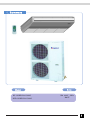
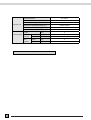
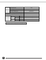
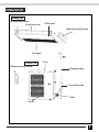
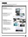
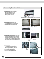
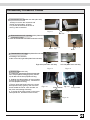
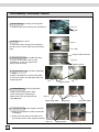
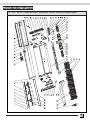
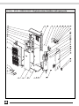
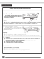
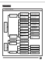
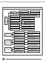
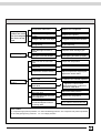
1
KF(R)-120DW/NA1-34005 Technical Service Manual
Introduction
In this technical service manual, you will find rich references to KF(R)-120DW/NA1-34005
model including photoes, technical specifications, explosive views, spare parts lists and
circuit diagrams. Service people and engineers of Gree' s customers and distributors would
find it a very handy source of technical information of our products.
Technical Support Group
Mar.2004
Contents
1 Summary
.......................................................1
2 ...................................................3
Technical and specifications
3 ........................................................7
Names and spare parts
Outlines and installation dimensions
4 ..................................................8
Working principle diagram
5 ......................................................10
6 .....................................................11
Circuit diagram
PCB function manual
7 .......................................12
Disassemble procedures
8 .......................................................27
9 .............................................35
Explosive view and spare parts lists
Care and maintenance
10 .....................................................40
11 ........................................................41
Trouble shooting
1. Summary
Model
KF-120DW/NA1-34005
KFR-120DW/NA1-34005
Note
3Ph 400V 50Hz
R407C
1
2.Technical specifications
Model
KF-120DW/NA1-34005
Function
COOLING
Power Supply (Phase-Frequency-Voltage)
3Ph – 400V – 50Hz
Capacity
(W)
12000
Rated Input
(W)
5300
Rated Current
(A)
8.9
3
Recycling Air Volume
(m /h)
Dehumidifying Volume
(L/h)
3.4
(W/W)
2.26
C.O.P / EER
Model
Motor Fan Speed (r/min) (H/M/L)
2200
KF-120D/NA1-34005
1100/1000/900
Output Power (w)
Fan Type-Piece
Diameter-Length (mm)
Evaporator
150
Centrifugal
φ155 X 175
Aluminum fin-copper tube
φ7
Pipe Diameter
Indoor unit
Row-Fin Gap (mm)
3-1.6
Working Area (m2)
1.34X 0.25
Swing Motor
MP35CA
Input Power of Motor (W)
Fuse (A)
Working Capacitor (uF)
Noise dB (A)
4
Controllor5A
transformer0.2A
3
≤55
Dimension (W/D/H)( mm)
1590X238X695
Dimension of Package (W/D/H)( mm)
1714X330X830
Net Weight /Gross Weight (kg)
Model
Input Power (W)
42
KF-120W/dNA1-34005
5150
Running Current (A)
8.2
L.R.A. (A)
48
Throttling Method
Compressor Model
Protector
Outdoor unit
fan - 4
Capillary
C-SBN373H8A
Internal overload protection
Starting Method
By capacitor
Working Temp Range
2~43℃
Condenser
Aluminum-copper
Pipe Diameter
Φ9.52
Rows - Fin Gap (mm)
2- 1.8
Working Area (m2)
Fan Motor Power(W)/Speed (rpm)
Fan Type-Piece
Fan Diameter (mm)
0.725X1.218
68/840
Axial fan –2
Ф450
3
Defrosting Method
Auto defrost
≤63
Noise dB (A)
Outdoor unit
Dimension (W/D/H)( mm)
1250X950X412
Dimension of Package (W/D/H)( mm)
1295X1110X450
Net Weight /Gross Weight (kg)
Refrigerant Charge (kg)
Length
Connecting Pipe
R407C/3.3
(m)
5
Outer
Liquid Pipe
(mm)
Φ12(1/2”)
Diameter
Gas Pipe
(mm)
Φ19(3/4”)
Max
Height
(m)
5
Distance
Length
(m)
10
The data of above are subject to be changed, please refer to the nameplate for reference.
4
112/133
Model
KFR-120DW/NA1-34005
Function
COOLING
Power Supply (Phase-Frequency-Voltage)
HEATING
3Ph – 400V – 50Hz
Capacity
(W)
12000
13000
Rated Input
(W)
5000
4600
Rated Current
(A)
8.3
Recycling Air Volume
(m /h)
Dehumidifying Volume
(L/h)
C.O.P / EER
7.8
3
(W/W)
Model
2200
3.4
2.4
2.83
KFR-120D/NA1-34005
Motor Fan Speed (r/min) (H/M/L)
1100/1000/900
Output Power (w)
150
Fan Type-Piece
Centrifugal
φ155X 175
Diameter-Length (mm)
Evaporator
Aluminum fin-copper tube
φ7
Pipe Diameter
Indoor unit
Row-Fin Gap (mm)
3-1.6
Working Area (m2)
1.34X 0.25
Swing Motor
MP35CA
Input Power of Motor (W)
Fuse (A)
4
controllor5A
Working Capacitor (uF)
transformer0.2A
3
≤55
Noise dB (A)
Dimension (W/D/H)( mm)
1590X238X695
Dimension of Package (W/D/H)( mm)
1714X330X830
Net Weight /Gross Weight (kg)
Model
Input Power (W)
Running Current (A)
L.R.A. (A)
Throttling Method
Compressor Model
Outdoor unit
fan - 4
Protector
Starting Method
Working Temp Range
Condenser
42/51
KFR-120W/dNA1-34005
4850
4450
7.1
7.6
55
Capillary
C-SBN353H8A
Internal overload protection
By capacitor
2~43℃
Aluminum-copper
Pipe Diameter
Φ9.52
Rows - Fin Gap (mm)
2- 1.8
Working Area (m2)
Fan Motor Power(W)/Speed (rpm)
Fan Type-Piece
0.725X1.218
68/840
Axial fan –2
5
Outdoor unit
Fan Diameter (mm)
Ф450
Defrosting Method
Auto defrost
≤63
Noise dB (A)
Dimension (W/D/H)( mm)
1250X950X412
Dimension of Package (W/D/H)( mm)
1295X1110X450
Net Weight /Gross Weight (kg)
112/133
Refrigerant Charge (kg)
R407C/3.4
Length
Connecting Pipe
(m)
5
Outer
Liquid Pipe
(mm)
Φ12(1/2”)
Diameter
Gas Pipe
(mm)
Φ19(3/4”)
Max
Height
(m)
5
Distance
Length
(m)
10
The data of above are subj ect to be changed, please referto the nameplate for reference.
6
3.Names of spare parts
Indoor unit
Left decoration plate
Air guide louver
LED board
Right decoration plate
Front grill
Outdoor unit
Wireless remote control
Air in
Wrapping tape
Connection pipe
Valve
Air out
7
4. Outlines and installation dimension
695
4.1 Outlines and dimensions of indoor unit
1590
238
150cm
or more
60cm
or more
60cm
or more
100cm
or more
8
30cm
or more
1250
4.2 Outlines and dimensions of outdoor unit
Handle
Gas pipe
Wire hole
More than
More than
Liquid pipe
Front grill
More than
More than 35cm
More than
9
5. Working principle diagram
5.1 Cooling system diagram for cooling only type
Evaporator
Cross flow fan
Capillary
Filter
Axial flow fan
Condenser
Gas-liquid separator
Compressor
When the power is on, indoor and outdoor units will start to run. The compressor sucks low-pressure refrigerant gas from the evaporator of indoor unit and
then discharges high-temperature, high-pressure refrigerant gas into outdoor condenser. Then air exchanges the heat with outdoor air and becomes refrigerant
liquid. The liquid is throttled by the capillary and changes into low-temperature and low-pressure liquid and then flows into indoor evaporator. Then liquid exchanges
the heat with the required air and changes into low-temperature and low-pressure refrigerant gas. the cycle introduced above goes on and on, and the demanded low
temperature environment is maintained.
5.2 Cooling system diagram for cooling/heating type
One-way valve
Evaporator
Cross flow fan
Main capillary Filter
Auxillary capillary
Axial flow fan
Condenser
electromagnetic
4-way valve
Heating
Cooling
Gas-liquid separator
Compressor
When the power is on, indoor and outdoor units will start to run. When the system operates in cool mode, the compressor sucks low-temperature, lowpressure refrigerant gas from indoor evaporator and then discharges high-temperature, high-pressure refrigerant gas into outdoor heat exchanger. With the
help of axial flow fan, the gas transfers its latent heat into outdoor air and becomes high-pressure refrigerant liquid. The liquid is throttled by the capillary
and changes into low-temperature and low-pressure liquid and then flows into indoor heat exchanger. With the help of centrifugal fan, the liquid evaporates
into low-temperature refrigerant gas and indoor air is cooled down. The refrigerant gas is sucked into the compressor and the cycle introduced above goes
on and on, and the demanded low temperature environment is maintained.
When the system operates in heat mode, 4-way valve changes its way and the refrigerant flows in the reversible cycle as the cool mode. The refrigerant
discharges its latent heat in the indoor heat exchanger, and sucks heat from outdoor heat exchanger and forms the heat pump cycle. This cycle goes on and
on, and the demanded high temperature environment is maintained.
10
6. Circuit diagram
The circuit diagram are subject to change , please refer to the ones on the machine.
KF-120DW/NA1-34005
KFR-120DW/NA1-34005
11
87. PCB function manual
7.1 Temperature parameter
①
②
③
④
The room ambient temp. (Tamb)
The room evaporator temp. (Teva)
The outdoor condensor temp.(Tcon)
The air exhaust temp.(Texh)
7.2 Foundamental functions
In each mode, the compressor starts at once, it will not stop within 6min according to the changes of Tamb,
when it stopped once, after 3mins delayed, can start it again.
7.2.1 COOL mode
When Tamb≥Tset+1℃, it will enter into COOL mode, the compressor, outdoor fan motor run.
Indoor fanmotor and swing motor run at the setting fan speed and setting.
When Tamb≤Tset-1℃, compressor, outdoor fan motor stop running. Indoor fan runs at set fan speed.
When Tset-1℃< Ta mb < Tset +1℃, keep the previous running mode.
In COOL mode, temp. setting range is 16℃~30 ℃.
Ambient Temp. Tamb
Start cooling
Tset
Setting temp. Tset
Tset
Keep the original running
6min
3min
6min
Stop cooling
Compressor
Outdoor fan
Indoor fan
Run at the setting speed
Running
Stop running
7.2.2 DRY Mode
When Tamb> Tset+2℃ , enter into COOL mode, the compressor, outdoor fan motor run, indoor fan motor
runs at setting low fan speed.
When Tset-2℃≤Ta mb≤ Tset+2℃ , compressor, outdoor fan motor run 6min, stop for 4min, that goes round
and round, indoor fan motor runs at low fan speed.
When Tamb <T set-2℃, the compressor and outdoor fan motor stop running, indoor fan motor runs at low
fan speed.
In DRY mode, temp. setting range is 16℃~30℃
12
Ambient
temp. Tamb
Start cooling
Tset
Setting temp. Tset
Dry operation
Tset
6min
4min
4min 6min
Stop cooling
Compressor
Outdoor fan
Low speed
Indoor fan
Low speed
Low speed Low speed Low speed
Running
Stop running
7.2.3 HEAT Mode
When Tamb≤Tset-1℃, enter into HEAT mode, reversing valve, compressor, outdoor fan motor start to work,
indoor fan motor runs at setting fan speed and anti-cool wind.
When Tamb≥ Tset +1℃,compressor, outdoor fan motor stop running, reversing valve is powered on, indoor
fan motor runs at low speed and after blowing for 10s later, it will stop.
When Tset-1℃< Tamb<Tset+, 1℃ it will keep the original status.
In HEAT mode, the temp. setting range is 16℃~30℃.
In HEAT mode, the unit is turned off or swtich to othermode, after compressor stopped for 2min, the 4-way valve
is powered off.
Stop heating
Tset
Ambient temp. Tamb
Setting temp. Tset
Keep the original running
Tset
6min
3min
6min
Start heating
Compressor
Outdoor fan
Indoor fan
Run at anti-cool wind
Run at anti-cool wind
Reversal valve
Running
Stop running
7.2.3.1 The conditions and processes of heating
When compressor starts HEAT running, indoor fan motor does not run, 3min later indoor fan motor runs
at the setting speed.
7.2.3.2 The defrosting working conditions:
When continuously heating operation for 44 minutes, continuously 1min detected Tcondensor ≤- 5℃ ,
defrost operation starts up, reversing valve, indoor and outdoor fan motor stop running.
When defrost operation start running for 10min or Tcondenser≥1 0℃ ,defrosting operation complete, reversing
valve, outdoor fan motor start to run at the same time, indoor fan motor runs at anti-cool wind.
13
Condenser pipe temp. Tcon
Outdoor fan
Reversal valve
Indoor fan
Run at anti-cool wind
44min 45min
Running
55min
Stop running
7.2.4 FAN mode
Indoor fan motor runs at setting fan speed:
AUTO
LOW
MED
HIGH
Temp. setting range is 16℃~30℃.
7.2.5 Auto mode
When Tamb> 26℃, it runs at cool mode, indoor setting temp. is 25℃.
When 20℃≤Tamb≤ 26℃, it will run in DRY mode, the inner setting temp. is 24℃ .
When Tamb< 20℃, it will run in HEAT mode, inner setting temp. is 20℃ , Tamp≥ 24℃, quit HEAT mode.
If it is cooling only type unit, when Tamb< 20 ℃ , it will run in FAN mode, inner setting temp. is 24℃.
When each mode start up, at least running for 30 seconds, Tamb then switch to AUTO mode running status.
Ambient
temp. Tamb
Start cooling
Dry mode
6min
3min
6min
Start heating
Compressor
Outdoor fan
Indoor fan
Running
Stop running
7.3 Protection Functions
7.3.1 Indoor antifreezing Protection
When in COOL mode, compressor started up 10min, when continuously 3min detected Teva<- 2℃, it shows
E2,
compressor stops running, outdoor and indoor fan motor, swing motor keep original running; when Teva> 6℃, compressor
has stopped 4min,
14
it will come back to display, controller runs at setting mode.
Indoor evaporator temp. Teva
10min
3min
4min
Compressor
Outdoor fan
Indoor fan
Swing motor
Stop running
Running
In DRY mode, starts running 6minutes, stop running 4minutes, after the compressor
running for 3min, if 3min continuously detected Ttube<--2℃, compressor stop running, outdoor, indoor fan motor
run at low fan speed, it displays E2. When Ttube>,6℃ , and compressor had stopped 4min, it come back to display,
controller runs at setting mode.
Evaporator
pipe temp.
Ttube
6min
4min
6min
4min 3min 3min 4min
Compressor
Outdoor fan
Indoor fan
Low fan speed
Low fan speed
Low fan speed
Running
Stop running
7.3.2 Compressor high pressure protection
When detected high pressure protection, E1 will be displayed.
When detected the compressor high pressure protection is released, E1 still display, that need to press
ON/OFF button to clean E1 displaying, and repress ON/OFF button to resume to run.
7.3.3 Compressor low pressure protection
When detected the low pressure switch tripped off, the unit will stop, after 3min it will resume to work automatically;
If E3 displayed, that can not resume automatically, so need to press ON/OFF button to turn off the unit, and repress
ON/OFF button for resuming.
When compressor stopped, detected low pressure switch tripped off, the unit stop, and E3 displayed, that cannot
resume automatically, need to press ON/OFF to turn off the unit, then repress ON/OFF button can resume to work.
7.3. 4 Air exhaust pipe high temperature protection
After compressor started up, when detected delivery temp. is too high or air exhaust sensor is short circuit (or open circuit),
according to indoor ambient temp. if achieved the setting temp. the unit will stop.
After compressor stopped for 3min, when delivery temp. is get right, unit resume to run.
15
If the above phenomenons existed, the unit cannot resume to run, E4 will be display. Press ON/OFF button to
turn off the unit, repress ON/OFF button return to run at the original running mode.
7.3.5 Indoor ultra high temperature protection
In HEAT mode, when detected the evaporator tube temp. is too high, outdoor fan motor stop running;
when evaporator tube temp. get right, outdoor fan motor start up.
7.3.6 Low voltage protection
Compressor is turned on, if the current had been detected exceed 22A, the room ambient temp. achieved the
setting temp., the unit will stop. When compressor had stopped 3min, it will automatically return to the original
setting mode. When displaying E5, can not automatically return to the original running mode, that need to press
ON/OFF button to turn off the unit, then repress the ON/OFF button to resume to work.
7.3.7 Error codes
E1: Compressor high pressure protection
E2: Indoor anti-freezing protection
E4: Air exhaust pipe high temp. protection
E5: Low pressure protection
E3: Compressor low pressure protection
7.4、Functions of Sleep and Timer:
7.4.1 Sleep
If controller is in COOL mode or DRY mode, after SLEEP operation run for 1hour, the presetting Tset will be
increased 1 ℃, 2hours later, it will be increased 1℃ , it has been decreased 2℃within 2hours in all, then it runs at the setting temp.
Set temp. Tset
Tset
Tset
Tset
1hour
2hours
If controller is in HEAT mode, after SLEEP operation run for 1hour, the presetting Tset will be decreased 1℃,
2 hours later it will be decreased 1℃ , it has been decreased 2 ℃ within 2hours in all, then it runs at the setting temp.
Tset
Tset
Tset
1hour
2hour
There is no SLEEP function in FAN mode and AUTO mode.
7.4.2 Timer on
At powered on, the timer on could be set, when the time arrived, the controller runs at the original setting mode,
the time interval is 0.5h, setting range is 0.5-24h.
7.4.3 Timer off
At operating, the timer off could be set, if the time arrived, the unit will turned off, the time interval is 0.5h,
setting range is 0.5-24h.
7.5 Other control
16
7.5.1 SWING Control
Use SWING button to start or stop the control, only when indoor fan motor is running the SWING operation is available.
7.5.2 The buzzer control
When controller is powered on or received the signals, the buzzer will sound.
7.5.3 The auto fan speed control of the fan motor
In HEAT mode:
If Tamb≥ Tset, is low speed
If Tset-3℃≤ Tamb<
Tset, is medium speed
If Tamb< Tset-3℃, is high speed
Ambient temp. Tamb
Tset
Tset
Indoor fan
High speed
Medium
speed
Low speed
In COOL mode:
If Tamb≤Tset, that is low speed
If Tset< Tamb≤ Tset+3℃, is medium speed
If Tamb>T set+3℃ , is high speed
Ambient temp. Tamb
Tset
Tset
Indoor fan Low speed Medium speed
High speed
In FAN mode:
The auto fan speed is as the same as the cool mode.
7.6 Indicators:
When power suply indicator is powered on, it will light, when powered off, it will extinguish. When it is indoor
anti-freezing protection, compressor high pressure protection, low pressure protection as well as
defrosting operations, the indicator flash.
The COOL indicator is lighting in COOL mode, DRY mode, Auto COOL, Auto DRY, in the other modes will extinguish.
The HEAT indicator is lighting in HEAT mode, and Auto HEAT mode, it will extinguish in other modes.
7.7 Memory function:
Memory contents: when MODE, SWING, TEMP. Setting, FAN Setting, TIMER Setting (When the time hasn't
arrived, and it powered off, the time will be recalculated; if the time had arrived and it is powered off, when
powered on, it will run at the mode which is the time arrived.)
After powered off, when powered on, the unit can automatically start up and run at the memory contents.
17
飞 碟 系 列
7.8 Names and functions of wireless remote control
Note:
Be sure that there are no obstructions between receiver and wireless remote control.
The wireless remote control could receive the signal within 10 meters.
Don't drop or throw the wireless remote control.
Don't let any liquid in the wireless remote control and put it directly
under the sunlight or any place where is very hot.
When it is pressed, the louvers
start to rotate automatically and
stop when repressed.
FAN button
Press this button to change
the fan speed of:
AUTO FAN
TEMP.button
Temp. setting: increase or
decrease 1 by pressing
or once.
When in
mode, setting
range is 16℃~30℃.
When in
mode, setting
range is 16℃~30℃.
When in mode, the setting.
range is 16℃~30℃.
In AUTO mode, the setting
temp. is unavailable.
“
“
“
“
” COOL mode
” DRY mode
” FAN mode
” HEAT mode
1/0 button
MODE button
Press this button,the operation will be changed
in the order of:
AUTO
18
Press this button, the unit
starts to run, when press
it once more, the unit will
stop running.
REMOTE CONTROL OPERATION PROCEDURE
SWING button
7.9 Names and functions of wireless remote control(Remove the cover)
Note:This type of wireless remote control is a kind of new current control.
Some buttons of the control which are not available to this air conditioner
will not be described below.
Liquid crystal displayer
REMOTE CONTROL OPERATION PROCEDURE
It shows all set contents.
SLEEP button
Press this button to set SLEEP
operation and stop when repressed.
TIMER OFF button
At stopping, press this button
to set TIMER OFF, each time
to press it , the time will be increased 0.5h.
It circulates as below:
0
24h
Cancel
TIMER ON button
At stopping, press this button
to set TIMER ON, each time
to press it, the time will be increased 0.5h.
It circulates as below:
0
24h
Cancel
19
7.10 COOL mode operation
Microcomputer will accord to the room sensor detected the temp. and setting temp. differences
to start the cool operation or not.
The room sensor detected temp. is higher than setting temp., the cool mode operate.
The room sensor detected temp. is lower than setting temp., indoor fan motor will stop running,
water valve will be turned off, cool operation will stop.
Temp. setting range is 16
~30
.
4.Press the button to start
REMOTE CONTROL OPERATION PROCEDURE
the FAN, and set the fan speed.
3.Press the SWING button,
the louver will automatically
swing and when repressed,
it will stop to swing.
5. Press the button to adjust the suitable temperature.
2. Press MODE
button to select
1. When pluged in,press 1/
0 button, the unit will start
to run.
20
7.11 HEAT mode operation
When room sensor detected temp. is lower than setting temp., heat mode start running.
When room sensor detected temp. is higher than setting temp., indoor fan motor stop
running, water valve is turned off, heat operation is stopped.
The setting range is 16 ~ 30
REMOTE CONTROL OPERATION PROCEDURE
3. Press SWING button, the
louver guide will automatically
swing, when repressed it, once
more, it will stop swinging.
4. Press FAN button to set
fan speed.
5. Press
the temp. set the
desired temp.
1. After powered on, press 1/0
button, air conditioner is running.
TIMER ON TIMER OFF ANION
SAVE
2. Press mode button, select
mode.
When cooling only unit receives heat mode
signal, it will run at fan mode.
21
7.12 DRY mode operation
When room sensor detected the temp. is lower than setting temp. 2℃ or more, the
water valve, indoor fan motor stop running.
When room sensor detected the temp. is between the ± 2℃ of the setting temp.
it will enter into dry mode operation, when room sensor detected the temp. is higher
than the setting temp.2℃ or more, it will enter into cool mode operation. The indoor
fan motor runs at low fan speed.
In this mode, the setting temp. range is 16 ~30
REMOTE CONTROL OPERATION PROCEDURE
3. Press SWING button,
it will swing automatically.
4. Press the button to adjust the suitable temperature.
2.Press MODE button,to
select the
(if the
has been selected, the fan
speed is unavailable.
22
1. When pluged in, press
1/0 button, the unit will
run.
7. 13 AUTO mode operation
REMOTE CONTROL OPERATION PROCEDURE
In AUTO mode, the standard cooling setting temp. is 25 ,
the standard heating setting temp. is 20 .
1. When plug in, press 1/0
unit will start to run.
2. Press MODE button to select
AUTO mode. Microcomputer will
accord to indoor temp. control unit
running in
modes to
achieve the best effect.
23
7.14 TIMER operation mode
At stopping, can set timer on,
each time to press TIMER ON
the time will be increased 0.5h,
circulates as below:
0
24h
Cancel
At running, can set timer off,
each time to press TIMER OFF,
the time will be increased 0.5h,
circulates as below:
0
24h
Cancel
24
7.15 SLEEP mode operation
In cool and dry modes, set the sleep operation and run for 1 hour later, the setting temp. will
be increased 1℃, 2hours later, the setting temp. will be increased 2℃ , then it runs at the
setting temp.
In heat mode, set the sleep operation and run for 1hour later,the setting temp. will be decreased
1℃, 2hours later, the setting temp. will be decreased 2℃ , then it runs at the setting temp.
4. Press the button to set
the FAN speed.
3. Press the button,
the guide louver will
automatically to swing.
6 Press SLEEP button,
enter into sleep mode,
when repressed the
button, quit the mode.
5. Press the buttons
to set desirable temperature.
2 Press MODE button
to select
modes.
1.When pluged in, press 1/0
the unit will start to run.
25
7.16 Guide for operation
NOTE:
Never mix new and used or different types of two batteries to
insert.
Take out the batteries,when
the wireless remote control
is not in use, to avoid the
the liquid damage it.
Insert two batteries
The operation range
should be in 10m or above.
The lifespan of the battery
is about 1 year.
The wireless remote control
should be placed about 1m
or more away from TV or
any other electric appliances.
Cover
Never use the old batteries.
26
REMOTE CONTROL OPERATION PROCEDURE
1. Remove the cover
from the back, take out
the old batteries.
2. Insert two batteries.
(pay attention to the
Polarity)
3. Re-attach the cover.
8.Disassembly procedures
8-1.Disassembly procedures for indoor unit
Dissassembly Procedures/Photoes
1.Removethefrontgrillassy
Front grill assy
Clasp
To remove the clasps of the front grill assy
by tools downward, until the front grill is opened.
Fig.8-1
2.Disassemble the left, right decoration plates
Disassemble the bolts of the photo
by screwdriver, then take out the
left, right decoration plates along
the direction of arrow.
Fig. 8-2
The position of bolts
Bolts
3.Disassemble electric box assy
a.Screw off 2pcs bolts with screwdriver
as shown in Fig.8-3, and take off the
electric box cover;
b.Screw off the bolts of Fig.8-4 with
screwdriver, take off capacitor
fixing plate, and disassemble the wires;
c.Screw off the bolts of Fig.8-5 with
screwdriver, take out the electric
box assy, and disassemble the wires.
Fig.8-3
Fig.8-5
Fig.8-4
Bolts
Fig.8-6
4.Remove the front panel assy
Use screwdriver to screw off 7pcs
bolt as shown in the fig. then along
the indicated direction can take off
the front panel assy.
Fig. 8-7
27
Dissassembly Procedures/ Photoes
5. Disassemble the guide louver assy
Take out the guide louver from
the guide louver holder, then
take out the both ends from
the swing motor.
Fig. 8-8
Assorted position of guide louver and guide louver holder
6. Disassemble the water-tray assy
To screw off 3pcs bolts in the photoes
can disassemble the water-tray assy.
Fig.8-9
Fig. 8-10
3pcs bolt
Fig.8-11
7.Disassemble swing louver and holder assy
Firstly to screw off 2pcs bolts at two ends
of the swing louver holder assy by screwdriver, then take out the swing louver holder
assy from the guide louver holder by hands.
Fig.8-12
Fig. 8-13
Bolts
Fig. 8-15
8. Disassemble evaporator assy
a. Screw off 2pcs bolt as shown in
Fig.8-14 with screwdriver, then take
out the evaporator outlet pipe block
assy;
b. Screw off the bolts as shown
in Fig.8-15 and Fig.8-16, take off
the evaporator assy, please handle
with care.
28
Bolts
Fig. 8-14
Bolts
Fig.8-16
Dissassembly Procedures/ Photoes
9. Disassemble the air outlet rear side plate assy
a. Firstly to remove the velveteen and
the left and right sides ' of liners;
b. To screw off the bolts as shown in
the Fig. with screwdriver.
Fig.8-17
Bolts
Fig. 8-18
10. Disassemble the left, right decoration plates assy
of the swing motor
To screw off the bolts with screwdriver as shown in the fig.
8-19
Fig.
Bolts
Fig. 8-20
Bolts
11.Disassemble the left, right sides plates foam sub-assy
According to the direction,
to take out the left, right sides plates foam sub-assy.
Right side plate foam sub-assy
Fig.
8-21
Left side plate foam sub-assy
Fig. 8-22
12. Disassemble motor assy
a. Pressing the clasp position where assorted with
front, rear propeller housing(Fig.8-23), then lift
up can take out the front propeller housing;
b. Holding the clasp position of rear propeller
housing (Fig.8-24) and lift it up, can take out
the rear propeller housing;
c.Then to loose the fixing bolts on the clutch
with special tools( Fig.8-25), then move the
clutch toward the louver, until can take out
the clutch and rotating axial assy;
d. To screw off the fixing screw on the louver
with special tool, and take out the louvers;
Fig. 8-23
Clasp position Fig.8-25
Fixing screw
Fig. 8-24
29
Dissassembly Procedures/ Photoes
13.Disassemble the bearing mounting plate
Fig. 8-26
To screw off 4pcs bolt in the fig. with screwdriver.
Bolt
14. Disassemble the motor
Fig.8-27
To loose the bolts in the fig with screwdriver,
can take out the motor clamp and motor fixing
hoop.
Bolt
Motor holder sub-assy
15. Disassemble the motor holder sub-assy
Fig. 8-28
To screw off the bolts in the fig. with
screwdriver, so that can take off the
motor holder sub-assy.
Tapping screw
16.Disassemble the motor holder, supporting
plate
Using the screwdriver to screw off the bolts
in the motor holder, rear side plate assy and
supporting plate.
Fig.8-30
Fig. 8-29
Tapping screw
17. Disassemble the left and right plates
Using the tool to take off the bolts
which are fixing the left and right
plates.(There are 2pcs M8 bolt and
2pcs M6b bolt)
Fig. 8-31
Fig.8-32
Right holder plate
Bolts(4pcs)
Left holder plate
18. Disassemble the motor support sub-assy
a. Using the screwdriver to take out the bolts
in the figure;
b. Using the tool to take out the bolts in the
fig, can take off the motor support sub-assy.
Bolts
Fig. 8-33
30
Tapping screw
Fig.8-34
8-2. The disassembly procedures for outdoor unit
The disassembly procedures for outdoor unit
1. Disassemble the top cover
Top cover
To screw off the bolts around the top cover
then lift it upward can take off the top cover.
As shown in Fig.
Fig.8-35
2.Disassemble the front side plate
To screw off the bolts around the top cover
3 pcs tapping screw
then downward it can take off the front
side plate. As shown in the Fig.
Fig. 8-36
3.Disassemble the cabinet
To screw off 8pcs tapping screw
which are fixing the cabinet, can
Tapping screw
take off the cabinet.
Fig. 8-37
Tapping screw
31
Dissassembly Procedures/ Photoes
4. Disassemble the electrical appliances mounting plate
Bolts
Disassemble 3pcs bolt which are fixing the electric mounting
plate, pull out the lead wire insert of the compressor and
fan motor, take out the electrical appliances mounting plate..
Fig. 8-38
5. Disassemble the rear side plate assy
Screw off 5pcs bolt of the rear side plate
Bolts
and 2pcs bolt of the rear grill, can disassemble the rear side plate assy. As shown
in Fig.
Bolts
Fig. 8-39
6. Disassemble the gas valve and liquid valve
To screw off 2pcs bolt which fix the gas valve,
then unsolder the gas valve.(Note: When unsolding the solder point, need to wrap the gas
valve entirely with wet cloth, avoid the valve
be damaged by high temperature), to screw
off 2pcs bolt of the liquid valve, and unsolder
the solder point of liquid valve and fork pipe,
and take off the liquid valve.
Bolts
liquid valve
Gas valve
Fig.8-40
32
Dissassembly Procedures/ Photoes
7.Disassemble the fan blade of outdoor unit
To screw off the laeotropic nut, can take off
the fan blade.
Laeotropic nut
Fig.8-41
8. Disassemble the outdoor unit motor
To screw off the fixing bolt of motor and motor
support, and pull out the connection wire of
the motor, can take off the motor.
Motor
Fig. 8-42
9. Disassemble four-way valve (only the cooling and heating unit has)
Unsolder 4pcs solder point of 4-way valve,
disassemble the connection wire of 4-way
valve wire loop, then can disassemble the
4-way valve. As shown in Fig.
Solder point
Fig. 8-43
33
Dissassembly Procedures/ Photoes
10. Disassemble the capillary
Unsolder the solder point of
the capillary, valve gate and
condenser gate, then can disassemble the capillary, make
sure that do not let any welding dregs to block the capillary.
As shown in right fig.
Capillary assy
Fig.8-44
11. Disassemble the compressor
Firstly to disassemble the relative pipelines
of compressor, then to disassemble 4pcs
bottom bolt of comjpressor, can disassemble
the compressor.
Bottom bolts
34
Fig.8-45
9.Explosive view and spare parts lists
9.1 For KF(R)-120DW/NA134005 Explosive view of indoor unit spare parts
35
9.2 Spare parts lists of indoor unit
No
36
Part Code
Description
Qty
KFR-120D/NA1-34005
KF-120D/NA1-34005
1
Left Decoration Plate
导板挤塑条左装饰板
26112415
26112415
2
Shaft of Louver I
导风板转轴I
10512025
10512025
2
3
Swing Louver Fixer
扫风叶片安装板
01332409
01332409
1
4
Louver Support
导风板支架
24212019
24212019
4
5
Louver Fixer
导风板固定架
24212018
24212018
3
6
Shaft of Louver II
导风板转轴II
10512026
10512026
3
7
Louver
导风板
10512408
10512408
1
8
Right Decoration Plate
导板挤塑条右装饰板
26112416
26112416
1
9
Left Swing Motor Fixer
扫风电机左安装板
26152005
26152005
1
10
Front Panel
面板组件
01532413
01532413
1
11
Display Box
电路板安装盒
20102138
20102138
1
12
Display Board
显示板6152AJ/6151AJ
30546104
30546103
1
13
Buttons Panel
按键面板组件
201620041
201620041
1
14
Right Swing Motor Fixer
扫风电机右安装板
26152006
26152006
1
15
Step Motor MP35CA
步进电机(导风) MP35CA
15212402
15212402
1
16
Motor Clamp
扫风电机压板
26112026
26112026
2
17
Water Tray
接水盘组件
01272408
01272408
1
18
Auxiliary Water Tray
辅助接水盘
01272409
01272409
1
19
Pipe Clip
管箍
70812001
70812001
1
20
Drainage Pipe
排水管组件
05235433
05235433
1
21
Handle
提手
26232001
26232001
4
22
Foam of Right Side Plate
右侧板泡沫
12312402
12312402
1
23
Right Fixing Palte
右安装板
01332404
01332404
1
24
Support of Motor Bearing
电机轴承座
01792408
01792408
2
25
Fixer of Motor Support
电机支架支撑板
01792407
01792407
1
26
Right Decoration Panel
右装饰板
26112027
26112027
1
27
Pipe Clamp
蒸发器出管压板
01072425
01072425
1
28
Electric Box
电器盒组件
01403242
01403242
1
29
Wire Base
压线座
24253001
24253001
1
30
Wire Clamp
压线板
24253002
24253002
1
31
Terminal Board RS9413G
接线板RS9413G
42010178
42010178
1
32
Fuse 5A 250VAC
保险管5A 250VAC VDE
46010013
46010013
1
33
Main PCB
主板6152J/6151J
30036052
30036051
1
34
Ring of Bearing
轴承胶圈
76512404
76512404
2
1
No
Part Code
Description
Qty
KFR-120D/NA1-34005
KF-120D/NA1-34005
35
Fan Bearing
风扇轴承
76512210
76512210
2
36
Transformer SC28D
电源变压器 SC28D
43110194
43110194
1
37
Cover of Electric Box
电器盒盖
1413008
1413008
1
38
Centrifugal Fan
离心风叶
10319051
10319051
4
39
Rotary Axis
转动轴组件
73012402
73012402
2
40
Capacitor CBB61 5uF/450
电容 CBB61 5uF/450
33010064
33010064
1
41
Capacitor Fixer
电容固定板
01722405
01722405
1
42
Motor FN150A
电机FN150A
15012405
15012405
1
43
Motor Fixer
电机固定箍
01722410
01722410
1
44
Motor Clamp
电机压板
01702405
01702405
1
45
Axes Connector
联轴器
73012403
73012403
2
46
Motor Fixing Plate
电机安装板组件
01332425
01332425
1
47
Front Snail Shell
前蜗壳
22202030
22202030
4
48
Rear Snail Shell
后蜗壳
22202029
22202029
4
49
Rear Side Plate
后侧板部件
01302411
01302411
1
50
Motor Support
电机支架组件
01702411
01702411
1
51
Filter
过滤网
11122013
11122013
1
52
Water Lead Plate
引水板组件
01362407
01362407
1
53
Front Grill
面板格栅
22412010
22412010
4
54
Front Grill Clip 2
面板格栅卡扣2
26252003
26252003
4
55
Remote Controller Y512
遥控器Y512(GREE)
30512506
30512506
1
56
Evaporator Assy
蒸发器部件
01002406
01002406
1
57
Front Grill Clip 1
面板格栅卡扣1
26252002
26252002
4
58
Temp Sensor
感温包
390001215
390001215
1
59
Temp Sensor Insert
感温包插片B
42020063
42020063
1
60
Cover of Evaporator
蒸发器盖板
01072409
01072409
1
61
Left Decoration Panel
左装饰板
26112028
26112028
1
62
Left Fixing Plate
左安装板
01332405
01332405
1
63
Left Side Foam
左侧板泡沫
12312401
12312401
1
64
Bearing Fixing Plate
轴承安装板
01332406
01332406
1
65
Rear Side Plate of Air Outlet
出风口后侧板
01302416
01302416
1
66
Connecting Lever
扫风连杆
10582008
10582008
2
67
Connecting Lever
扫风连杆
10582009
10582009
4
68
Swing Louver
扫风叶片
10512027
10512027
26
The above data are subject to change without notice.
37
9.3 For KF(R)-120DW/NA134005 Explosive view of outdoor unit spare parts
38
9.4 Spare parts lists of outdoor unit
No
1
2
3
Part Code
Description
Signal Cable
Signal Cable
Connecting Cable
Qty
KFR-120W/dNA1-34005
KF-120W/dNA1-34005
信号控制线 #
40032142
信号控制线 #
\
400321531
1
40032143
电源连接线 #
400204771
400204772
1
400204771
1
1
4
Power Cord
电源连接线 #
40020454
5
Front grill
面罩
22265251
22265251
2
6
Front plate
外罩
01435433
01435433
1
7
Axial flow fan
轴流风叶
10335253
10335253
2
8
Motor FW68T
电机 FW68T
15013302
15013302
2
9
Motor support
电机支架组件
01705433
01705433
1
10
Condenser assy
冷凝器组件
01133455
011054381
1
11
Temp Sensor
热敏电阻
34030030
\
1
感温包架
24215101
\
01255262
1
12
Sensor holder
13
Top cover
顶盖
01255262
14
Rear grill padding
网罩垫块
76315251
76315251
1
15
Rear grill
网罩
01475431
1
16
Temp Sensor
热敏电阻
01475431
34030031
\
1
17
Temp Sensor Insert
感温包插片B
42020063
\
1
18
Electric box assy
电器盒组件
01405471
01405471
1
19
Ac contactor
交流接触器
44010226
44010226
1
20
Reverse Phase Protector
逆相保护器
46020052
46020052
1
21
Over current protector
过流保护器
46020103
46020103
1
22
Wiring terminal T8F0A
接线板 T8F0A
42011224
42011036
1
23
Capacitor 3.5uF
电容CBB61 3.5uF/450V
33010010
33010010
1
24
Wiring terminal 2-8
接线板 2-8
42011103
42011103
1
25
Wiring clamp
电线夹 #
71010102
71010102
2
26
Isolation Washer C
绝缘垫片C
70410523
70410523
1
27
Capillary Assy
毛细管部件
030037131
030037141
1
28
4-way Valve
四通阀(5匹)
430004051
\
1
29
4-way Valve Coil
四通阀配件
430004005
\
1
30
Gas-liquid Separator
汽液分离器部件
07225433
07225433
31
Temp Sensor
热敏电阻
34030019
34030019
1
32
Temp Sensor Insert
感温包插片E
42020066
42020066
1
33
Rear Side Plate
后侧板组件
01303712
01303712
1
34
Handle
把手
26235253
26235253
3
35
Valve Support
阀门支架组件
01715001
01715001
1
36
Liquid Valve Assy
小阀门组件
07103704
07103704
1
37
Gas Valve Assy
大阀门组件
07103703
07103703
1
38
Drainage Connector
室外机排水接头
06123401
\
1
39
Compressor C-SBN353H8A
压缩机C-SBN353H8A
00100157
00100332
1
40
Overload Protector
(过载内置)
Built in
Built in
41
Compressor Gasket
压缩机胶垫
76710209
76710209
4
42
Metal Base
底盘组件
01205433
01205433
1
43
Isolation Sheet Assy
隔板组件
01235440
01235440
1
44
Front Plate
前侧板
01305431
01305431
1
1
1
39
10.Care and maintenance
Warning: Please turn power off before maintenance.
10.1 Cleaning the filter
Take out the filter, use the dust collector to clean, if it is
too dirty could use the soap water to clean. Make sure to
dry the filter then can reinsert it.
Advice:
If the filter is too dirty that will affect the air in volume, so that make the system overloaded
and consum more than 6% of electric energy. So it is very necessary to clean the filter.
10.2 Cleaning the equipment, spare parts
Use the dry, soft cloth or vacuum cleaner to clean
the unit and wireless remote control. If the cloth is wet,
please dry it after cleaned.
Warning:
Never use the benzene, gasoline or something is hard to clean.
Never use the hot water (40 above) for cleaning, in order to avoid some spare part or part deformation.
10.3 Check in use
Check that are there any obstructions block the air inlet or air outlet vents of indoor unit and outdoor unit.
If there is not air filter when the unit is running, the dust will be accumulated and may cause
the malfunction, ususally it is necessary to install the filter.
Check that the drainage pipe is bent or damaged.
To check the equipment is normal or correct installaed.
10.4 Check after use
Pull out the plug, cut off the power supply.
Clean the filter and equipment, spare parts.
Start fan motor for 2-3 hours in order to clean, dry the equipmenbt internal.
40
11.Trouble shooting
Trouble shooting
The circuit breaker trip
off( Or fuse is melt)
When circuit breaker is
set to "ON", will trip off
at once.
When turn the unit to
"ON", thebreaker trip off
in a few minutes.
No power supply
Air conditioner can not start
Wireless remote control
sending malfunction
Cool (Heat) is poor
Both indoor unit and
outdoor unit can not
start.
Check the breaker,
test the resistance
of short circuit.
Check power supply circuit
Check the wireless
remote control
The plug is not inserted
well or poor connection.
Check and insert the plug
fix it firmly.
Wrong wire connection
between indoor and outdoor unit.
According to the
electric diagram
to check the circuit and correctlyconnect.
The fuse of controller is
melt
Replace the fuse of
controller
Is the wire connection
of strong or light
current plates fixed
well
Please fix the connection
wire firmly.
Is the output wire of
transformer
firmed or is there any output.
Please fix the connection
wire, and check the output
voltage.
The setting temp.
is not suitable.
Adjust the setting temp.
Is cool (heat) over load
suitable.
Please check the pretested
cool(heat) load
Malfunction in four-way
valve
Replace the 4-way valve
Refrigerant volume
is not enough
Charge the refrigerant
Compressor malfunction
Refrigerant flowing
malfunction
Earth, tested insulated
to confirm whether it is
electricity leakage or not.
The flow volume
is not enough
Change the compressor
To open the valve
adequately
41
Cool (Heat) is poor
Set the fan speed to high
or middle speed
Fan speed is too low
The installation place of
indoor unit is not suitable
The outdoor unit installation place should be
well ventilated, and should be installed awning.
Indoor unit filter blocked
To clean the filter termly
Outdoor unit heat exchanger
blocked
Clean the dust adhering on the
surface of heat exchanger
Leakage between high and low
pressure in the compressor
Replace the compressor
Capillary blocked partially
Refrigerant leakage
Replace the capillary
Check leakage,add refrigerant
Outdoor unit one-way valve
blocked
Replace the one-way valve
Indoor fan motor burnt or
broken
When setting FAN,
the fan motor
doesn't work
Wrong wiring
Fan motor capacity is broken
or damaged
When in cool,heat
mode, the outdoor
unit and compressor
do not work
In cool, heat mode,
compressor run, outdoor fan does not
run.
42
Clean the filter
Air filter is blocked
Air circulation
volume
is not enough.
Mend or replace fan motor
According to circuit diagram to connect
wire correctly.
Replace the same model, same
specification capacity
The loop of relay is broken
Replace the relay
Poor connection of the relay
Replace the relay
The setting temp. is not suitable
Adjusting the setting temp.
Outdoor fan motor is broken
Mend or replace fan motor
Wrong wiring
The capacitor of outdoor
unit fan motor is broken
According to circuit diagram
to connect wire correctly.
Replace the capacitor of fan motor
Compressor malfunction
Replace the compressor
In COOL, DRY mode,
outdoor fan motor
runs, but compressor does not operate.
Water leakage
Abnormal sound and
vibration
Compressor running capacity
broken
Replace the capacity
Voltage is too low or too high
Suggest to equip the manostat
Wrong wiring
According to the circuit diagram
to wire correctly.
Water drainage blocked or
broken
Replace water drainage pipe
The wrapping of refrigerant
pipe joint is not well sealed
Rewrapping and bind up tightly
Indoor unit fan touches other
parts
Adjust the fan position
There are abnormities in the
indoor unit
Take out the abnormities
Compressor vibrates terribly
Adjust compressor support pad,
tighten the loosen bolts
Outdoor pipelines collide
each other
To deleave the collided pipelines
Indoor metal sheets collide
each other
.
1. Tighten the connect bolt
2.Stickthe dumping cushion ts.
between metal shee
Outdoor unit fan collide
with body case
Adjust fan blade position
There are abnormal sound in
the compressor
Replace the compressor
When heating, there are abnormal electromagnetic sound in
the 4-way valve.
The electromagnetic valve internal short
circuit, replace the electromagnetic valve.
Error codes:
E1: Compressor high pressure protection E2: Indoor antifreezing protection E3: Compressor low pressure protecition
E4: Air outlet pipe high temp. protection E5: Low voltage protection
43