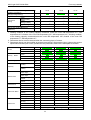
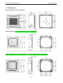
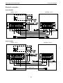
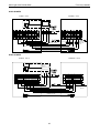
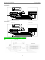
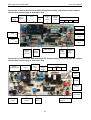
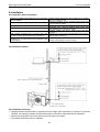
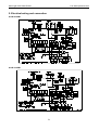
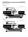
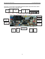
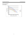
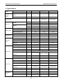
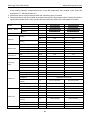
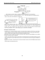
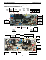
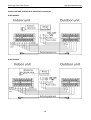
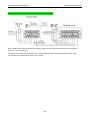
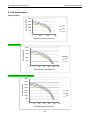
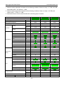
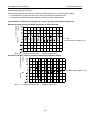
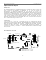
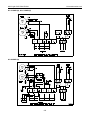
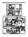
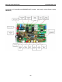
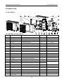
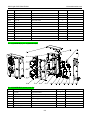
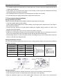
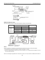
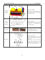
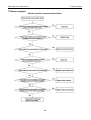
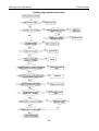
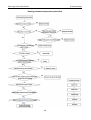
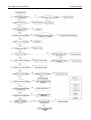
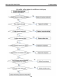
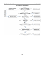
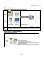
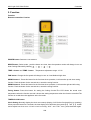
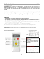
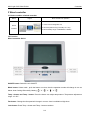
1
AUX Light CAC R410A 50Hz Service manual (Light Commercial 50Hz R410A) (RUSSIA) 1 AUX-Light CAC 50Hz R410A General description Contents Part 1 General description ..................................................................................................3 Part 2 Indoor unit .................................................................................................................7 Part 3 Universal outdoor unit..........................................................................................138 Part 4 Trouble shooting...................................................................................................178 Part 5 Controller...............................................................................................................208 Part 6 Sensor resistance table........................................................................................ 217 2 AUX-Light CAC 50Hz R410A General description Part 1 General description Nomenclature 3 AUX-Light CAC 50Hz R410A General description Unit appearance Series Picture of the indoor unit Four-way Cassette 12k Btu/h 18k Btu/h 24k Btu/h 36k Btu/h 48k Btu/h 60k Btu/h Ceiling &Floor 12k Btu/h 18k Btu/h 24k Btu/h 36k Btu/h 48k Btu/h 60k Btu/h Low ESP Duct 12k Btu/h Mid ESP Duct 18k Btu/h 24k Btu/h 36k Btu/h 48k Btu/h 60k Btu/h 36k Btu/h 48k Btu/h 60k Btu/h High ESP Duct 24k Btu/h 4 AUX-Light CAC 50Hz R410A Cooling capacity (Btu/h) 12k Btu/h General description 18 k Btu/h 24 k Btu/h Universal outdoor unit 5 36 k Btu/h 48 k 60 k Btu/h Btu/h AUX-Light CAC 50Hz R410A Indoor unit Part 2. Indoor unit Four-way cassette ...............................................................................................................7 Ceiling & floor type ............................................................................................................36 Low static pressure duct type ..........................................................................................64 Middle static pressure duct type ......................................................................................81 High static pressure duct type ....................................................................................... 112 6 AUX-Light CAC 50Hz R410A Four-way cassette Four-way cassette 1.Feature ...............................................................................................................................8 2.Specfication ....................................................................................................................10 3.Capacity Amendment .....................................................................................................16 4.Demension ......................................................................................................................18 5.Electrical wiring and connection ...................................................................................19 6.Installation.......................................................................................................................26 7.Explode view ...................................................................................................................31 7 AUX-Light CAC R410A 50Hz Four-way cassette 1Feature Four-way cassette type air conditioner (Cooling-only or heat pump), is installed under the ceiling, compared with Floor &Standing type A/C, it has following advantages: saving room space; Ceiling installation combining with the decoration, makes the room more elegant; Flexible installation in anywhere in the ceiling and 4-direction blowing, makes the indoor temperature is even and makes you feel more comfortable, so Cassette type A/C is a perfect replacing Product of Floor & Standing type A/C. Application occasions: Small super market, restaurant, office, meeting room, villa meeting room, family bedroom and so on, and it can even be used as the updating Product for modern residential A/C. Features: ◇Concealed design, ceiling installation, room space saving, it is very suitable for family or office occasion; ◇With Setting or Auto two operation modes, four-way blowing, strong circulating wind, multi wind speed, the cooling or heating capacity can reach to each corner of the room; ◇One-step formed shell by mold, appearance is elegant; ◇Special insulation design, achieves high heat insulation efficiency, and no condensation on shell; ◇Built-in drain pump, drain-head height is up to 1.2meters, creating the ideal solution for perfect water drainage, also construction and installation is much easier and convenient; ◇Long term air filter, wash period is two times longer than normal filter, and maintenance is free; ◇3D helix air blade ensures the air flow sufficiently, reduces the unit thickness, and reduces the operation noise greatly; ◇Plastic drip tray adopts innovative foam-PS combined with plastic technical, the thickness of plastic reaches 1mm, avoid any leakage; ◇6 segments heat exchanger, increase exchanging area, the efficiency of heat exchanging increased by 10%~15%; ◇Ingenious hook design, the panel is convenient to install or remove; ◇Fresh air intake design, leading in fresh air to improve indoor air quality anytime; ◇3-phase power supply type units with low ambient temperature cooling function, which makes the unit can run normally on the condition that the ambient temperature falls down to -15℃; ◇Auto-restart function; ◇Standard remote controller and optional wired controller; ◇Auxiliary electric heater for heat pump unit, with fast heating and low ambient temperature heating functions; ◇Failure automatic detection, if there is a failure, the indicator will flash and the failure code will display on the wired controller, the failure cause is easier to be found. 8 AUX-Light CAC R410A 50Hz Four-way cassette Function introduction Type ALCA-C(H)**R1(B) Item High pressure protection Low pressure protection Compressor overloading protection High exh. temperate protection Protection Phase protection(Phase-loss, phase- reverse) Over-heating protection Anti-freezing protection Sensor failure alarm Failure code display Cooling Heating 3-Speed Comfort Adjustable ESP Auto-restart(Optional) Anti-cold wind Afterheat wind blowing Timing ON/OFF Time display Operation mode display Fan speed display Operation Defrost display Timing ON/OFF display Wind angle display Sleeping mode display Auto start Dehumidifying Running Auto defrost Ventilation function Low ambient temperature cooling Health Washable air filter Fresh air interface Left/right drainage(optional) Installation Left/right pipe connection(optional) Down/back air suction(optional) Installation indicating board Remarks: ● Stands for “YES” 12/4 18/4 24/4 36/5 48/5 60/5 - - ● - - ● ● ● ● ● ● ● - ● ● ● ● ● ● ● ● ● ● ● ● ● ● ● ● ● ● - - - ● - - ● - - ● ● ● ● ● ● ● - ● ● ● ● ● ● ● ● ● ● ● ● ● ● ● ● ● ● - - - ● - - ● - - ● ● ● ● ● ● ● - ● ● ● ● ● ● ● ● ● ● ● ● ● ● ● ● ● ● - - - ● ● ● ● ● ● ● ● ● ● ● ● ● - ● ● ● ● ● ● ● ● ● ● ● ● ● ● ● ● ● ● - - - ● ● ● ● ● ● ● ● ● ● ● ● ● - ● ● ● ● ● ● ● ● ● ● ● ● ● ● ● ● ● ● - - - ● ● ● ● ● ● ● ● ● ● ● ● ● - ● ● ● ● ● ● ● ● ● ● ● ● ● ● ● ● ● ● - - - ● - Stands for “NO” 9 AUX-Light CAC R410A 50Hz Four-way cassette 2. Specfication Indoor Model ALCA-C12/4R1 Panel MB13 MB13 MB13 AL-H12/4R1(U) AL-C18/4R1(U) Indoor ALCa-12A4/R1-C7 ALCa-H12A4/R1-C7 ALCa-18A4/R1-C7 Panel MB13 MB13 MB13 AL-12A4/R1(T) AL-H12A4/R1(T) AL-18A4/R1(T) 220~240,50,1 220~240,50,1 220~240,50,1 12000 12000 18000 Outdoor Power Supply Cooling Capacity Heating Electric Data Performance V~,Hz, Ph Btu/h KW 3.6 3.6 5.3 Btu/h / 13500 / W / 3.9 / KW 1.19 1.19 1.76 KW / 1.20 / A 5.45 5.45 8.05 A / 5.49 / Rated Cooling Power Input Rated Heating Power Input Rated Cooling Current Rated Heating Current EER W/W 3.03 3.03 3.01 COP W/W / 3.25 / YDK30-6E1 YDK30-6E1 YDK30-6E1 TELING TELING TELING 30*1 30*1 30*1 Model Indoor Fan Motor Brand Output Power x Fan quantity Capacitor uF Speed (Hi/Mi/Lo) r/min Number Of Row Tube Pitch(a)x Row Pitch(b) Fin Pitch Indoor Coil Indoor Unit Panel ALCA-C18/4R1 AL-C12/4R1(U) Outdoor Factory Model ALCA-H12/4R1 Fin Material Tube Outside Dia.and Material Coil Length x Height x Width Heat Exchanging Area Indoor Air Flow (Hi/Mi/Lo) Noise Level(Hi/Mi/Lo) Net Dimension (W*H*D) Packing Dimension (W*H*D) Net Weight W 1.5 1.5 2.5 920/850/750 920/850/750 920/850/750 2 2 2 mm 20.5×12.7 20.5×12.7 20.5×12.7 mm 1.5 1.5 1.4 Hydrophilic aluminum fin mm φ7,Inner grooved φ7,Inner grooved φ7,Inner grooved mm 1160×164×25.4 1160×164×25.4 1160×164×25.4 m2 4.34 4.34 5.76 620/496/434 620/496/434 900/720/630 41/38/32 41/38/32 41/38/32 mm 615×615×263 615×615×263 615×615×263 mm 700×700×330 700×700×330 700×700×330 3 m /h dB(A) Kg 20 20 20 Gross Weight Net Dimension (W*H*D) Packing Dimension (W*H*D) Net weight Kg 25 25 25 mm 650×650×55 650×650×55 650×650×55 mm 710×710×80 710×710×80 710×710×80 Kg 3 3 3 Gross weight Kg 5 5 5 10 AUX-Light CAC R410A 50Hz Liquid Side Gas Side Max. Refrigerant Refrigerant Pipe Pipe Length Max. Difference In Level Operation Temperature Range Ambient Temperature Range(Cooling/Heating) Application Area Power Wiring( Indoor) Connection Wiring Power Wiring( Outdoor) Signal Wiring Wireless Remote Controller Qty’per 20’& 40’&40HQ(Only For Reference) Four-way cassette mm 6.35 6.35 6.35 mm 12.7 12.7 12.7 m 15 15 20 m 10 10 15 ℃ 16~32 16~32 16~32 ℃ -5~49 -5~49/-15~24 -5~49 13-21 21-35 m 2 13-21 mm 2 3×1.5mm mm 2 / mm 2 Set 2 3×1.5mm 2 3×2.5mm / 2 3×1.5mm +1mm 2 2 3×1.5mm +2×1mm 2 / 2 2 3×2.5mm +1mm YKR-H/009E YKR-H/009E YKR-H/009E 61/132/167 61/132/167 54/112/135 2 Note: 1. Working condition of the cooling capacity measured: Inside the room DB temperature 27℃,WB temperature19℃;Outside of the room DB temperature 35℃,WB temperature 24℃;Working condition of the heating capacity measured:Inside the room DB temperature 20℃,Outside of the room DB temperature 7℃,WB temperature 6℃. 2. Parameters above are all measured when the connecting pipe is 5 meters. 3. Parameters above may be modified as product improvement. We keep the right to change the product specifications without prior notice, please take the parameters listed on the nameplate as criterion. Indoor Model ALCA-H18/4R1 Panel Outdoor Indoor Factory Model Panel Outdoor Power Supply Cooling Capacity Heating Electric Data Performance Rated Cooling Power Input Rated Heating Power Input Rated Cooling Current Rated Heating Current EER COP V~,Hz, Ph Btu/h ALCA-H24/4R1 MB13 MB12 MB12 AL-H18/4R1(U) ALCa-H18A4/R1-C 7 MB13 AL-C24/4R1(U) AL-H24/4R1(U) ALCa-24B4/R1-C7 ALCa-H24B4/R1-C7 MB12 MB12 AL-H18A4/R1(T) AL-24B4/R1(T) AL-H24B4/R1(T) 220~240,50,1 220~240,50,1 220~240,50,1 18000 24000 24000 KW 5.3 7.2 7.2 20000 / 27500 W 5.8 / 8.1 KW 1.76 2.39 2.39 KW 1.80 / 2.50 A 8.05 10.94 10.94 A 8.24 / 11.49 W/W 3.01 3.01 3.01 Btu/h W/W Model Indoor Fan Motor ALCA-C24/4R1 Brand Output Power x Fan quantity Capacitor W Speed (Hi/Mi/Lo) r/min 3.22 / 3.24 YDK30-6E1 YDK30-6 Q YDK30-6 Q TELING HUATE HUATE 30*1 30*1 30*1 uF 2.5 3 3 920/850/750 500/400/320 500/400/320 11 AUX-Light CAC R410A 50Hz Number Of Row Tube Pitch(a)x Row Pitch(b) Fin Pitch Indoor Coil Indoor Unit Panel Fin Material Tube Outside Dia.and Material Coil Length x Height x Width Heat Exchanging Area Indoor Air Flow (Hi/Mi/Lo) Noise Level(Hi/Mi/Lo) Net Dimension (W*H*D) Packing Dimension (W*H*D) Net Weight Gross Weight Net Dimension (W*H*D) Packing Dimension (W*H*D) Net weight Four-way cassette 2 2 2 mm 20.5×12.7 20.5×12.7 20.5×12.7 mm 1.4 1.6 1.6 Hydrophilic aluminum fin mm φ7,Inner grooved φ7,Inner grooved φ7,Inner grooved mm 1160×164×25.4 2142×205×25.4 2142×205×25.4 2 5.76 10.02 10.02 m /h 3 900/720/630 1300/1040/910 1300/1040/910 dB(A) 41/38/32 45/42/36 45/42/36 mm 615×615×263 835×835×240 835×835×240 mm 700×700×330 910×910×320 910×910×320 Kg 20 27 27 Kg 25 34 34 mm 650×650×55 950×950×55 950×950×55 mm 710×710×80 1000×1000×100 1000×1000×100 Kg 3 5 5 m Gross weight Kg 5 7 7 Liquid Side mm 6.35 9.52 9.52 mm 12.7 15.88 15.88 m 20 30 30 m 15 15 15 ℃ 16~32 16~32 16~32 ℃ -5~49/-15~24 -5~49 -5~49/-15~24 21-35 28-47 28-47 / / Gas Side Max. Refrigerant Pipe Length Max. Difference In Level Operation Temperature Range Ambient Temperature Range(Cooling/Heating) Application Area Power Wiring( Indoor) Connection Power Wiring Wiring( Outdoor) Signal Wiring Refrigerant Pipe Wireless Remote Controller Qty’per 20’& 40’&40HQ(Only For Reference) m 2 mm 2 3×2.5mm mm 2 / mm 2 3×2.5mm +2×1mm Set 2 2 3×4mm 2 2 2 3×1mm +2×1mm 3×4mm 2 2 2 3×1mm +3×1mm YKR-H/009E YKR-H/009E YKR-H/009E 54/112/135 34/72/87 34/72/87 2 Note: 1. Working condition of the cooling capacity measured: Inside the room DB temperature 27℃,WB temperature19℃;Outside of the room DB temperature 35℃,WB temperature 24℃;Working condition of the heating capacity measured:Inside the room DB temperature 20℃,Outside of the room DB temperature 7℃,WB temperature 6℃。 2. Parameters above are all measured when the connecting pipe is 5 meters. 3. Parameters above may be modified as product improvement. We keep the right to change the product specifications without prior notice, please take the parameters listed on the nameplate as criterion. Indoor ALCA-C36/5R1B ALCA-H36/5R1B ALCA-C48/5R1B Model Panel MB12 MB12 MB12 AL-C36/5R1B(U) AL-H36/5R1B(U) AL-C48/5R1B(U) Factory Model Indoor ALCa-36A5/R1 ALCa-H36A5/R1 ALCa-48A5/R1 Outdoor 12 AUX-Light CAC R410A 50Hz Four-way cassette -C7B -C7B -C7B MB12 MB12 MB12 AL-36A5/R1(T)-B AL-H36A5/R1(T) -B AL-48A5/R1(T) -B 380~415,50,3 380~415,50,3 380~415,50,3 36000 36000 48000 10.6 10.6 14.0 Btu/h / 40000 / W / 11.7 / KW 3.77 3.77 4.87 KW / 3.50 / A 7.22 7.22 9.32 A / 6.69 / Panel Outdoor Power Supply Cooling Capacity Heating Electric Data Performance Rated Cooling Power Input Rated Heating Power Input Rated Cooling Current Rated Heating Current EER COP V~,Hz, Ph Btu/h KW W/W 2.81 2.81 2.87 W/W / 3.34 / YDK45-6 Q YDK45-6 Q YDK80-6-50 Q HUATE HUATE KANGBAO Model Indoor Fan Motor Brand Output Power x Fan quantity Capacitor W 45*1 45*1 80*1 uF 4 4 6 Speed (Hi/Mi/Lo) r/min 650/520/450 650/520/450 685/540/450 2 2 2 mm 20.5×12.7 20.5×12.7 20.5×12.7 mm 1.4 1.4 1.4 Number Of Row Tube Pitch(a)x Row Pitch(b) Fin Pitch Indoor Coil Indoor Unit Panel Refrigerant Pipe Fin Material Tube Outside Dia.and Material Coil Length x Height x Width Heat Exchanging Area Indoor Air Flow (Hi/Mi/Lo) Noise Level(Hi/Mi/Lo) Net Dimension (W*H*D) Packing Dimension (W*H*D) Net Weight Gross Weight Net Dimension (W*H*D) Packing Dimension (W*H*D) Net weight Hydrophilic aluminum fin mm φ7,Inner grooved φ7,Inner grooved φ7,Inner grooved mm 2142×205×25.4 2142×205×25.4 2142×246×25.4 2 12.76 12.76 15.60 3 m /h 1500/1200/1050 1500/1200/1050 1800/1440/1260 48/45/39 48/45/39 50/47/41 mm 835×835×240 835×835×240 835×835×280 mm 910×910×320 910×910×320 910×910×360 Kg 27 27 30 Kg 34 34 37 mm 950×950×55 950×950×55 950×950×55 mm 1000×1000×100 1000×1000×100 1000×1000×100 m dB(A) Kg 5 5 5 Gross weight Kg 7 7 7 Liquid Side mm 9.52 9.52 9.52 Gas Side Max. Refrigerant Pipe Length Max. Difference In Level mm 15.88 15.88 19.05 m 50 50 50 m 30 30 30 13 AUX-Light CAC R410A 50Hz Operation Temperature Range Ambient Temperature Range(Cooling/Heating) Application Area Power Wiring( Indoor) Connection Power Wiring Wiring( Outdoor) Signal Wiring Wireless Remote Controller Qty’per 20’& 40’&40HQ(Only For Reference) Four-way cassette ℃ 16~32 16~32 16~32 ℃ -5~45 -5~45/-15~24 -5~45 42-70 42-70 56-93 m 2 mm 2 3×1mm mm 2 5×2.5mm mm 2 2×1mm Set 2 3×1mm 2 2 2 5×2.5mm 2×1mm 3×1mm 2 2 2 5×2.5mm 2×1mm 2 2 YKR-H/009E YKR-H/009E YKR-H/009E 30/64/77 30/64/77 20/42/44 Note: 1. Working condition of the cooling capacity measured: Inside the room DB temperature 27℃,WB temperature19℃;Outside of the room DB temperature 35℃,WB temperature 24℃;Working condition of the heating capacity measured:Inside the room DB temperature 20℃,Outside of the room DB temperature 7℃,WB temperature 6℃. 2. Parameters above are all measured when the connecting pipe is 5 meters. 3. Parameters above may be modified as product improvement. We keep the right to change the product specifications without prior notice, please take the parameters listed on the nameplate as criterion. Model Indoor ALCA-H48/5R1B ALCA-C60/5R1B ALCA-H60/5R1B Panel MB12 MB12 MB12 AL-H48/5R1B(U) ALCa-H48A5/R1C7B MB12 AL-H48A5/R1(T)-B AL-C60/5R1B(U) ALCa-60A5/R1C7B MB12 AL-60A5/R1(T) -B AL-H60/5R1B(U) ALCa-H60A5/R1C7B MB12 AL-H60A5/R1(T) -B 380~415,50,3 380~415,50,3 380~415,50,3 48000 60000 60000 Outdoor Indoor Factory Model Panel Outdoor Power Supply Cooling Capacity Heating Electric Data Performance Rated Cooling Power Input Rated Heating Power Input Rated Cooling Current Rated Heating Current EER COP V~,Hz, Ph Btu/h KW 14.0 17.6 17.6 53000 / 63500 W 15.5 / 18.5 KW 4.87 6.28 5.71 KW 5.13 / 6.00 A 9.32 12.02 12.02 A 9.82 / 11.48 W/W 2.87 3.08 3.08 W/W 3.02 / 3.08 YDK80-6-50 Q YDK80-6-50 Q YDK80-6-50 Q KANGBAO KANGBAO KANGBAO 80*1 80*1 80*1 Btu/h Model Indoor Fan Motor Indoor Coil Brand Output Power x Fan quantity Capacitor W Speed (Hi/Mi/Lo) r/min Number Of Row Tube Pitch(a)x Row Pitch(b) Fin Pitch uF 6 6 6 685/540/450 685/540/450 685/540/450 2 2 2 mm 20.5×12.7 20.5×12.7 20.5×12.7 mm 1.4 1.4 1.4 Fin Material Tube Outside Hydrophilic aluminum fin mm φ7,Inner grooved 14 φ7,Inner grooved φ7,Inner grooved AUX-Light CAC R410A 50Hz Four-way cassette Dia.and Material Indoor Unit Panel Coil Length x Height x Width Heat Exchanging Area Indoor Air Flow (Hi/Mi/Lo) Noise Level(Hi/Mi/Lo) Net Dimension (W*H*D) Packing Dimension (W*H*D) Net Weight Gross Weight Net Dimension (W*H*D) Packing Dimension (W*H*D) Net weight mm 2142×246×25.4 2142×246×25.4 2142×246×25.4 2 15.60 15.60 15.60 m3/h 1800/1440/1260 1800/1440/1260 1800/1440/1260 dB(A) 50/47/41 50/47/41 50/47/41 mm 835×835×280 835×835×280 835×835×280 mm 910×910×360 910×910×360 910×910×360 Kg 30 30 30 Kg 37 37 37 mm 950×950×55 950×950×55 950×950×55 mm 1000×1000×100 1000×1000×100 1000×1000×100 Kg 5 5 5 m Gross weight Kg 7 7 7 Liquid Side mm 9.52 9.52 9.52 mm 19.05 19.05 19.05 m 50 50 50 m 30 30 30 ℃ 16~32 16~32 16~32 ℃ -5~45/-15~24 -5~45 -5~45/-15~24 56-93 64-107 Gas Side Max. Refrigerant Pipe Length Max. Difference In Level Operation Temperature Range Ambient Temperature Range(Cooling/Heating) Application Area Power Wiring( Indoor) Connection Power Wiring Wiring( Outdoor) Signal Wiring Refrigerant Pipe Wireless Remote Controller Qty’per 20’& 40’&40HQ(Only For Reference) m 2 mm 2 3×1mm mm 2 5×2.5mm mm 2 2×1mm Set 2 3×1mm 2 2 5×2.5mm 2×1mm 64-107 2 3×1mm 2 2 2 5×2.5mm 2×1mm 2 2 YKR-H/009E YKR-H/009E YKR-H/009E 20/42/44 20/42/44 20/42/44 Note: 1. Working condition of the cooling capacity measured: Inside the room DB temperature 27℃,WB temperature19℃;Outside of the room DB temperature 35℃,WB temperature 24℃;Working condition of the heating capacity measured:Inside the room DB temperature 20℃,Outside of the room DB temperature 7℃,WB temperature 6℃。 2. Parameters above are all measured when the connecting pipe is 5 meters. 3. Parameters above may be modified as product improvement. We keep the right to change the product specifications without prior notice, please take the parameters listed on the nameplate as criterion. 15 AUX-Light CAC R410A 50Hz Four-way cassette 3.Capacity Amendment 3.1 Running range Cooling capacity (Btu/h) 12000 18000 24000 36000 48000 60000 Power supply 220-240V~/50Hz 380-415V 3N~/50Hz Voltage 187~242V 320~420V -5~49℃ -5~45℃ Cooling Ambient temperature Heating -15~24℃ Amendment coefficient of cooling capacity under different indoor/outdoor DB/WB temperature Indoor air inlet temperature℃ DB WB Outdoor air inlet DB temperature℃ 25 30 35 40 43 23 16 0.98 0.94 0.89 0.85 0.82 25 18 1.05 1 0.95 0.90 0.87 27 19 1.1 1.05 1 0.95 0.91 28 20 1.12 1.07 1.02 0.96 0.93 30 22 1.19 1.13 1.08 1.02 0.99 32 24 1.26 1.20 1.15 1.08 1.05 Actual cooling capacity calculation: Actual cooling capacity=amendment coefficient of cooling capacity × nominal cooling capacity ——nominal cooling capacity could be found from the performance parameters list ——amendment coefficient of cooling capacity could be found from table above. Amendment coefficient of heating capacity under different indoor/outdoor DB/WB temperature Outdoor air inlet WB temperature ℃ Indoor air inlet DB temperature ℃ -5 0 6 10 15 16 0.65 0.80 1.02 1.13 - 18 0.61 0.76 1.02 1.12 - 20 0.6 0.75 1 1.11 1.25 21 0.59 0.72 0.99 1.1 1.24 22 0.58 0.71 0.97 1.09 1.23 24 0.56 0.7 0.96 1.08 1.22 Actual heating capacity calculation: Actual heating capacity=amendment coefficient of heating capacity × nominal heating capacity ——nominal heating capacity could be found from the performance parameters list ——amendment coefficient of heating capacity could be found from table above. 16 AUX-Light CAC R410A 50Hz Four-way cassette Amendment coefficients of heating and cooling capacity under different height drop Different Cooling Capacity modified coefficients at different height: Height Cooling Difference H(m) Equivalent pipe length EL (m) Note: H = Height of Outdoor Unit - Height of Indoor Unit Different Heating Capacity modified coefficients at different height: Height Difference H(m) Heating Equivalent pipe length EL(m) Note: H = Height of Outdoor Unit - Height of Indoor Unit 17 AUX-Light CAC R410A 50Hz Four-way cassette 4. Demension ALCA-C(H)12/4R1, ALCA-C(H)18/4R1 ALCA-C(H)24/4R1, ALCA-C(H)36/5R1B、ALCA-C(H)36/5R1C ALCA-C(H)48/5R1B, ALCA-C(H)60/5R1B,ALCA-C(H)48/5R1C, ALCA-C(H)60/5R1C 18 AUX-Light CAC R410A 50Hz Four-way cassette 5. Electrical wiring and connection ALCA-H12/4R1, ALCA-H18/4R1 ALCA-C12/4R1, ALCA-C18/4R1 19 AUX-Light CAC R410A 50Hz Four-way cassette ALCA-H24/4R1 ALCA-C24/4R1 20 AUX-Light CAC R410A 50Hz Four-way cassette ALCA-C(H)36/5R1B, ALCA-C(H)48/5R1B, ALCA-C(H)60/5R1B ALCA-C(H)36/5R1C, ALCA-C(H)48/5R1C, ALCA-C(H)60/5R1C 21 AUX-Light CAC R410A 50Hz Four-way cassette Electrical connection ALCA-H12/4R1 indoor unit outdoor unit Multicore signal Wired controller Power cable Control wire Control wire Signal wire ALCA-C12/4R1 indoor unit Multicore signal wire outdoor unit Wired controller Power cable Control wire Signal wire 22 Control wire AUX-Light CAC R410A 50Hz Four-way cassette ALCA-H18/4R1 indoor unit outdoor unit Multicore signal Wired controller Power cable Control wire Control wire Signal wire ALCA-C18/4R1 Indoor unit Outdoor unit Multicore signal wire Wired controller Power cable Control wire Signal wire 23 Control wire AUX-Light CAC R410A 50Hz ALCA-H24/4R1 Four-way cassette Indoor unit Outdoor unit Multicore signal wire Wired controller Power cable Control wire Control wire Signal wire ALCA-C24/4R1 Indoor unit Outdoor unit Multicore signal wire Wired controller Power cable Control wire Control wire Signal wire ALCA-C(H)36/5R1B, ALCA-C(H)48/5R1B, ALCA-C(H)60/5R1B ALCA-C(H)36/5R1C, ALCA-C(H)48/5R1C, ALCA-C(H)60/5R1C 24 AUX-Light CAC R410A 50Hz Four-way cassette Introduction of Control Board sockets QRDL-3F(2S)-SYE1 (indoor unit) (match with the outdoor unit which the Power supply is 220V-240V, 1PH) Neutra l insert Electric heating output Compressor output 4-way valve Outdoor fan output Drainage pump output Indoor fan output High Mid Low Neutral 4-DIP switch Float switch Transformer input Return air temp. Transformer output Indoor coil temp. Remote control receiver Step motor output 3-DIP switch Wired control receiver Outdoor coil temp. Introduction of control board QRD-SN3F(2S)-SYE1 sockets (Indoor unit) (match with the outdoor unit which the Power supply is 380V-415V, 3PH) Electric heating output Transformer input Neutral insert input Indoor fan output Drainage pump output input High Mid Low Neutra l Buzzer Float switch input 4-DIP switch Return air temp. Indoor coil temp input Transformer output Remote control receiver 3-DIP switch Wired control receiver 25 AUX-Light CAC R410A 50Hz Four-way cassette 6 Installation 6.1 Preparation before installation Please buy following spare parts from your local market before installation Hung bolts M12, 4 pcs Drainage pipe PVC Copper connecting pipe Adhesive belt (big size) 5 pcs, (small size) 5 pcs Heat insulation material used to connect copper pipe (PE foam material, its thickness is more than 8mm) Power cable, electrical wire between indoor and outdoor unit(Must be in accordance with the wire diameter in the wiring diagram) Besides general implements, other implements are needed when connecting the pipe Acetylene cylinders, oxygen cylinders (when longer pipe used it should be welded) One set pipe cut machine. (cut copper pipe) Refrigerant cans, electronic balance (when longer pipe used additional gas should be charged) Pressure gauges, pipe clamp, welding torch, 2B silver electrode Wrench 2 pcs, one of them is with adjustable torque wrench (42N.m,65N.m,100N.mm) Nitrogen cylinder (in order to prevent oxidation when welding, using Nitrogen to replace the air) 6.2 Installation diagram 6.3 Installation precaution ◇ Hanging location should be able to support the unit’s weight, there should be no increase in noise and vibration. If the hanging location needs reinforcement, it should be reinforced before installation; ◇ Choose the space above the ceiling that can put the indoor unit inside; ◇ The location should be easy for drainage; 26 AUX-Light CAC R410A 50Hz Four-way cassette ◇ The unit should not be installed in the heat source, steam source oil mist places (such as machine room, kitchen, laundry room, mechanical workshop, etc.) in order to avoid performance degradation, electric shock, plastic parts corrosion which lead to unit broken; ◇ Choose the location at least 1 meter away from TV and radio, in order to avoid interference to them ◇ There is no obstacles getting in the way of air circulation, cold air can evenly spread to all corners of the room; ◇ In order to facilitate maintenance and repair, there should be certain distance between indoor unit and obstacles; ◇ Refrigerant R22 is used for this unit, which is non-flammable and non-toxic gas. As the proportion of refrigerant is bigger than air, so if it leaks the gas will be filled on the ground. Therefore, if the units mounted on a closed room there must be good ventilation to prevent suffocation. In case of leakage of refrigerant, units should immediately stop running, and contact with maintenance personnel in time. There must be no fire at the site, because the refrigerant will turn to harmful gas when get to the fire. 6.4 The distance between indoor unit and obstacle 6.5 Indoor unit suspension ◇ Select the suspension foundation: The suspension foundation is a structure of either wooden frame or reinforced concrete. It must be firm and reliable to bear at least 4 times weight of itself and capable of bearing vibration for long periods. ◇ Fixing of suspension foundation: ◇ Fix the suspension bolts either as shown in the picture or by a steel or wooden bracket. 27 AUX-Light CAC R410A 50Hz Four-way cassette ◇ If this unit is installed on a sloping ceiling, a cushion block should be installed between the ceiling and the air outlet panel, in order to ensure that the unit is installed on a level surface. This is as shown in the drawing as follows: ◇ Adjust the relative position of the suspension hook on the suspension bolt so that the unit can be in level position in all directions. Check with a level gauge after the installation is complete in order to ensure that the indoor unit is horizontal, otherwise it will cause water leakage, air leakage etc. ◇ Tighten the bolt and ensure that four hooks are in close contact with the nuts and washers, and the unit is suspended firmly and reliably onto the hooks. ◇ After the unit is installed ensure it is secure and does not shake or sway. ◇ Ensure that the centre of the indoor unit is in alignment with the centre of the opening in the ceiling. 6.6 Drainage pipe installation The drain pipe should be properly insulated to prevent the generation of condensation. Heat insulation material: the thickness of rubber insulation pipe should be more than 8mm ◇ Drainage pipe must have a downward gradient (1 / 50 1 / 100).If the drain pipe is installed ups and 28 AUX-Light CAC R410A 50Hz Four-way cassette downs, it will cause water backflow or leakage etc. More than 1:100 ◇ The unit has a drain pump which will lift up to 1200mm. However after the pump stops the water still in the pipe will drain back and may overflow the drain tray causing a water leak. For this reason please install the drain pipe as shown Less than 300mm Less than 600mm Less than 800mm (Unit: mm) ◇ When draining multiple units into a common drain line, this common drain should be installed about 100mm below each units drain outlet, as shown in the drawing. More than 100mm ◇ When finish installation please carry out the drainage test to ensure that the water flow through the pipeline fluently, and carefully observe the junction to ensure that there is no water leakage. If the unit is installed in the newly built house, strongly recommend that this test taken before the ceiling installation. Even it is the heating only unit, this test is unavoidable. 6.7 Panel installation As to the MB12 panel please refer to the following picture, the panel has four hooks which attach to corresponding hangers on the unit and the panel should be positioned using these first. The panel is then fixed into position by four bolts which are accessed through the four corner panels on the grille. Notes: When installing please ensure that the position of swing motor is in accordance with the position of the pipes of the unit. 29 AUX-Light CAC R410A 50Hz Four-way cassette 6.8 Connect duct, fresh air ventilation In order to meet different customers’ requirements and their different usage environment, 3hp and 5hp indoor unit reserves one fresh air ventilation hole and four duct connection holes. The fresh air can be introduced from outside or through duct. ◇ Fresh air ventilation: In the corner of the unit there is a circular fresh air connection hole, if users want this feature, please cut down the circular metal sheet and connect it to the duct. Fresh air replacement hole is connected to the return air inlet of the indoor unit, when in the process of operation due to the negative pressure, the fresh air can be introduced from outside. ◇ Connect to duct: There are four rectangular connection holes on the four sides of the unit. If users what to connect it to the duct, please close the outlet to the side which needs connecting to the duct as well as cut down the rectangular metal sheet. Notes: 1.Only under special usage that it is allowed to connect to duct pipe and the length of the duct pipe should be less than 5 meters. 2. Using the duct that can prevent frost and noise. 3. Using heat insulation material to seal the junction between duct and the unit. 30 AUX-Light CAC R410A 50Hz Four-way cassette 7. Explode view ALCA-C(H)12/4R1, ALCA-C(H)18/4R1 N0. Chinese name Part Name Quantity Remark 1 面板 MB13(英文) Panel MB13 1 1.1 回风格栅组件 Return-air grille assembly 1 1.2 空气过滤网 Air filter net 1 1.3 导风叶片 guide wind vane 4 1.4 步进电机 Step motor 4 24BYJ48-2 1.5 显示灯板 Display board 1 SX-DISP-01 1.6 面板围框组件 Panel frame assembly 1 2 电控盒盖 Cover for electric components 1 3 电控盒总成 Electric assembly 1 3.1 电容 capacitance 1 31 2.5μF/450V a.c AUX-Light CAC R410A 50Hz Four-way cassette 3.2 控制板 PCB board 1 QRDL-3F(2S)-SYE1 3.3 变压器 Transformer 1 TDB-8-B(PTC) 3.4 端子板 7 位 Terminal board 1 600V 2.5mm2 3.5 传感器 5K3470 XH2 0.5m(塑封) Sensor 1 1 3.6 传感器 5K3470 XH2 0.9m(铜壳) Sensor 2 1 4 橡胶塞 Rubber plug 1 5 接水盘组件 Water pan 1 6 蒸发器总成 Evaporator assembly 1 6.1 蒸发器组件 Evaporator part 1 6.2 蒸发器出气管组件 Evaporator outlet tube assembly 1 6.3 蒸发器进液管组件 Evaporator inlet tube assembly 1 7 蒸发器挂钩 Evaporator Pothook 2 8 蒸发器连接板 Evaporator connect board 1 9 排水泵 Drain pump 1 9.1 浮子开关 Bodder switch 1 9.2 排水泵支架 Drain pump support 1 10 风轮 Wind wheel 1 Ф283×166 11 电机 Fan motor 1 YSK30-6E1 12 电机支架 motor holder 1 13 风道 Air passage 1 14 接水盘固定板 Water pan holder 4 15 挂钩 Pothook 4 16 围板 A Boarding A 1 16.1 围板 B Boarding B 1 17 阀板 A Valve board A 1 17.1 阀板 B Valve board B 1 18 底盘组件 Chassis 1 19 塑料排水接管 Plastic drainage pipe 1 19.1 塑料排水软管 Plastic drain hose 1 32 PLD-700 AUX-Light CAC R410A 50Hz Four-way cassette ALCA-C(H)24/4R1, ALCA-C(H)36/5R1B, ALCA-C(H)48/5R1B, ALCA-C(H)60/5R1B ALCA-C(H)36/5R1C, ALCA-C(H)48/5R1C, ALCA-C(H)60/5R1C ALCA-C(H)24/4R1 spare part list N0. Chinese name Part Name Quantity Remark 1 面板 MB12(英文) 1.1 面板边角盖板 Panel cover board 2 1.2 回风格栅组件 Return-air grille assembly 2 1.3 空气过滤网 Air filter 1 1.4 面板围框组件 Panel frame assembly 1 1.4.1 面板围框 Panel frame 1 1.4.2 导风叶片 Wind-guiding blade 4 1.5 步进电机 Step motor 1 24BYJ48-2 1.6 显示灯板 Display board 1 SX-DISP-01 2 导风圈总成 Guide wind loop assembly 1 2.1 导风圈 Guide wind loop 1 2.2 导风圈配板 Guide wind board 1 2.3 端子板 7 位 TerminAL board 1 3 接水盘组件 Defrosting pan 1 4 蒸发器总成 Evaporator assembly 1 4.1 蒸发器组件 Evaporator part 1 4.2 蒸发器出气管组件 Evaporator outlet tube assembly 1 4.3 蒸发器进液管组件 Evaporator inlet tube assembly 1 5 电控盒总成 Electric box assembly 1 5.1 控制板 PCB board 1 Panel MB12 33 1 QRDL-3F(2S)-SYE1 AUX-Light CAC R410A 50Hz Four-way cassette 5.2 变压器 Transformer 1 TDB-8-B(PTC) 5.3 电容 capacitance 1 3μF/450V a.c 5.4 传感器 5K3470 XH2 0.5m(塑封) Sensor 1 1 5.5 传感器 5K3470 XH2 1.5m(铜壳) Sensor 2 6 底盘泡沫组件 Chassis foam assembly 7 底盘组件 Chassis assembly 1 8 配管盖板 Piping cover board 1 9 电机 Fan motor 1 10 排水泵总成 Drain pump assembly 1 10.1 排水泵支架 Drain pump support 1 10.2 水泵减振橡胶 Pump damping rubber 3 10.3 排水泵 Drain pump 1 10.4 排水软管(水泵用) Drain flexible pipe (Drain pump) 1 10.5 排水接管 Drain pipe 1 10.6 浮子开关 GMF-31 Float switch 1 11 风轮 Wind wheel 1 Ф462×147(3P) Quantity Remark 1 1 YDK30-6 Q PLD-1200 ALC(H)36/5R1B, ALC(H)36/5R1C spare part list N0. Chinese name Part Name 1 面板 MB12(英文) Panel MB12 1 1.1 面板边角盖板 Panel cover board 2 1.2 回风格栅组件 Return-air grille assembly 2 1.3 空气过滤网 Air filter 1 1.4 面板围框组件 Panel frame assembly 1 1.4.1 面板围框 Panel frame 1 1.4.2 导风叶片 Wind-guiding blade 4 1.5 步进电机 Step motor 1 24BYJ48-2 1.6 显示灯板 Display board 1 SX-DISP-01 2 导风圈总成 Guide wind loop assembly 1 2.1 导风圈 Guide wind loop 1 2.2 导风圈配板 Guide wind board 1 2.3 端子板 7 位 TerminAL board 1 3 接水盘组件 Defrosting pan 1 4 蒸发器总成 Evaporator assembly 1 4.1 蒸发器组件 Evaporator part 1 4.2 蒸发器出气管组件 Evaporator outlet tube assembly 1 4.3 蒸发器进液管组件 Evaporator inlet tube assembly 1 5 电控盒总成 Electric box assembly 1 5.1 控制板 PCB board 1 QRD-SN3F(2S)-SYE1 5.2 变压器 Transformer 1 TDB-8-B(PTC) 5.3 电容 capacitance 1 4μF/450V a.c 5.4 传感器 5K3470 XH2 0.5m(塑封) Sensor 1 1 5.5 传感器 5K3470 XH2 1.5m(铜壳) Sensor 2 1 6 底盘泡沫组件 Chassis foam assembly 1 7 底盘组件 Chassis assembly 1 8 配管盖板 Piping cover board 1 9 电机 Fan motor 1 10 排水泵总成 Drain pump assembly 1 10.1 排水泵支架 Drain pump support 1 10.2 水泵减振橡胶 Pump damping rubber 3 34 YDK45-6 Q AUX-Light CAC R410A 50Hz Four-way cassette 10.3 排水泵 Drain pump 1 10.4 排水软管(水泵用) Drain flexible pipe (Drain pump) 1 10.5 排水接管 Drain pipe 1 10.6 浮子开关 GMF-31 Float switch 1 11 风轮 Wind wheel 1 PLD-1200 Ф462×147(3P) ALCA-C(H)48/5R1B, ALCA-C(H)60/5R1B, ALCA-C(H)48/5R1C, ALCA-C(H)60/5R1C, spare part list N0. Chinese name Part Name Quantity Remark 1 面板 MB12(英文) 1.1 面板边角盖板 Panel cover board 2 1.2 回风格栅组件 Return-air grille assembly 2 1.3 空气过滤网 Air filter 1 1.4 面板围框组件 Panel frame assembly 1 1.4.1 面板围框 Panel frame 1 1.4.2 导风叶片 Wind-guiding blade 4 1.5 步进电机 Step motor 1 24BYJ48-2 1.6 显示灯板 Display board 1 SX-DISP-01 2 导风圈总成 Guide wind loop assembly 1 2.1 导风圈 Guide wind loop 1 2.2 导风圈配板 Guide wind board 1 2.3 端子板 7 位 TerminAL board 1 3 接水盘组件 Defrosting pan 1 4 蒸发器总成 Evaporator assembly 1 4.1 蒸发器组件 Evaporator part 1 4.2 蒸发器出气管组件 Evaporator outlet tube assembly 1 4.3 蒸发器进液管组件 Evaporator inlet tube assembly 1 5 电控盒总成 Electric box assembly 1 5.1 控制板 PCB board 1 QRD-SN3F(2S)-SYE1 5.2 变压器 Transformer 1 TDB-8-B(PTC) 5.3 电容 capacitance 1 6μF/450V a.c 5.4 传感器 5K3470 XH2 0.5m(塑封) Sensor 1 1 5.5 传感器 5K3470 XH2 1.5m(铜壳) Sensor 2 6 底盘泡沫组件 Chassis foam assembly 1 7 底盘组件 Chassis assembly 1 8 配管盖板 Piping cover board 1 9 电机 Fan motor 1 10 排水泵总成 Drain pump assembly 1 10.1 排水泵支架 Drain pump support 1 10.2 水泵减振橡胶 Pump damping rubber 3 10.3 排水泵 Drain pump 1 10.4 排水软管(水泵用) Drain flexible pipe (Drain pump) 1 10.5 排水接管 Drain pipe 1 10.6 浮子开关 GMF-31 Float switch 1 11 风轮 Wind wheel 1 Panel MB12 1 1 35 YDK80-6-50 Q PLD-1200 Ф470×170 AUX-Light CAC 50Hz R410A Ceiling &floor type Ceiling & floor type 1.Feature .............................................................................................................................37 2.Specfication ....................................................................................................................39 3.Capacity amendment ......................................................................................................45 4.Demension ......................................................................................................................47 5.Electrical wiring ..............................................................................................................48 6.Installation.......................................................................................................................56 7.Explode view ...................................................................................................................58 36 AUX-Light CAC 50Hz R410A Ceiling &floor type 1.Feature Ceiling& Foor type A/C (Cooling-only or Heat pump) can be installed under the ceiling and also on the floor. Compared with normal Floor &Standing type A/C, it can be hoisted under the ceiling,saving room space, it is also the updating Product for Floor & Standing type A/C. Application occasions: Small super market, restaurant, office, meeting room, villa living room, family bedroom, and it can even be used as the updating Product for modern residential A/C. Features: ◇ Suspended ceiling, installation under ceiling, saving room space, it is very suitable for family or office place; ◇ ◇ ◇ ◇ ◇ ◇ Convenient and flexible for indoor unit installation, can be installed under the ceiling or on the floor; With Setting or Auto two operation modes, multi fan speed, makes you feel more comfortable; Shell was formed by mold, and the appearance is “slim”, “elegant”, “fashion” and “comfortable”; Special insulation design, achieves high heat insulation efficiency and no condensation on shell; Long term air filter, the wash period is two times longer than normal filter, maintenance is free; Adopting low noise centrifugal fan, strong wind but quiet operation, the silence design achieves harmony residential living; ◇ All the installation and maintenance can be done in the bottom of unit, saving the maintenance space; ◇ 3-phase power supply type units with low ambient temperature cooling function, which makes the unit can run normally on the condition that the ambient temperature falls down to -15℃;; ◇ Standard remote controller and optional wired controller; ◇ Auxiliary electric heater for heat pump unit, with fast heating and low ambient temperature heating functions; ◇ Failure automatic detection, if there is a failure, the indicator will flash and the failure code will display on the wired controller, the failure cause is easier to be found.. ◇ Filter to dismantle to wash convenience, don't need to make use of any tool, can move to dismantle to filter a net to clean. ◇ Ultra slim design, the thickness only 205 mm, and have vertical and horizontal swing function. 37 AUX-Light CAC 50Hz R410A Ceiling &floor type Function introduction Type Protection Comfort Operation Running Health Installation ALCF-C(H)**R1(B) Item 12/4 18/4 24/4 36/5 48/5 60/5 High pressure protection - - - ● ● ● Low pressure protection - - - ● ● ● Compressor overloading protection ● ● ● ● ● ● High Ext. temperate protection - - - ● ● ● Phase protection(Phase-loss, phase- reverse) - - - ● ● ● Over-heating protection ● ● ● ● ● ● Anti-freezing protection ● ● ● ● ● ● Sensor failure alarm ● ● ● ● ● ● Failure code display ● ● ● ● ● ● Cooling ● ● ● ● ● ● Heating ● ● ● ● ● ● 3-Speed ● ● ● ● ● ● Adjustable ESP - - - - - - Auto-restart(Optional) ● ● ● ● ● ● Anti-cold wind ● ● ● ● ● ● Afterheat wind blowing ● ● ● ● ● ● Timing ON/OFF ● ● ● ● ● ● Time display ● ● ● ● ● ● Operation mode display ● ● ● ● ● ● Fan speed display ● ● ● ● ● ● Defrost display ● ● ● ● ● ● Timing ON/OFF display ● ● ● ● ● ● Wind angle display ● ● ● ● ● ● Sleeping mode display ● ● ● ● ● ● Auto start ● ● ● ● ● ● Dehumidifying ● ● ● ● ● ● Auto defrost ● ● ● ● ● ● Ventilation function ● ● ● ● ● ● Low ambient temperature cooling ● ● ● ● ● ● Washable air filter ● ● ● ● ● ● Fresh air interface - - - - - - Left/right drainage - - - - - - Left/right pipe connection - - - - - - Down/back air suction - - - - - - Installation indicating board - - - - - - Remarks:● Stands for “YES” - Stands for “NO” 38 AUX-Light CAC 50Hz R410A Ceiling &floor type 2.Specfication Indoor ALCF-C12/4R1 ALCF-H12/4R1 ALCF-C18/4R1 Outdoor AL-C12/4R1(U) AL-H12/4R1(U) AL-C18/4R1(U) ALCe-12A4/R1-C ALCe-H12A4/R1-C ALCe-18A4/R1-C 5 5 5 AL-12A4/R1(T) AL-H12A4/R1(T) AL-18A4/R1(T) 220~240,50,1 220~240,50,1 220~240,50,1 12000 12000 18000 3.6 3.6 5.3 Btu/h / 13500 / kW / 3.9 / Rated Cooling Power Input kW 1.13 1.13 1.72 Rated Heating Power Input kW / 1.15 / Rated Cooling Current A 5.17 5.17 7.87 Rated Heating Current A / 5.26 / EER W/W 3.19 3.19 3.08 COP W/W / 3.39 / Model YSK-40W-4 YSK-40W-4 YSK-40W-4 Brand HUATE HUATE HUATE Model Factory Model Indoor Outdoor V~,Hz,P Power Supply h Cooling Capacity Heating Electric Data Performance Indoor Fan Fotor Btu/h kW Output Power x Fan quantity W 40*1 40*1 40*1 Capacitor uF 2.5 2.5 2.5 Speed (Hi/Mi/Lo) r/min 1300/1010/900 1300/1010/900 1300/1010/900 2 2 3 Number Of Row Indoor Coil Tube Pitch(a)x Row Pitch(b) mm 20.5×12.7 20.5×12.7 20.5×12.7 Fin Spacing mm 1.6 1.6 1.6 Fin Material Tube Outside Dia.and Material Coil Length x Height x Width Heat Exchanging Area Hydrophilic aluminum fin mm φ7,Inner grooved φ7,Inner grooved φ7,Inner grooved mm m 570×246×25.4 570×246×25.4 570×246×38.1 2 4.00 4.00 6.00 3 Indoor Air Flow (Hi/Mi/Lo) m /h 620/496/434 620/496/434 850/680/595 Noise Level(Hi/Mi/Lo) dB(A) 39/36/30 39/36/30 43/40/34 Net mm 929×660×205 929×660×205 929×660×205 mm 1010×720×280 1010×720×280 1010×720×280 Net Weight Kg 24 24 25 Gross Weight Kg 27 27 28 Liquid Side mm 6.35 6.35 6.35 Refrigerant Gas Side mm 12.7 12.7 12.7 Pipe Max. Refrigerant Pipe 15 15 20 Indoor Unit Dimension (W*H*D) Packing Dimension (W*H*D) Length m 39 AUX-Light CAC 50Hz R410A Max. Difference In Level Ceiling &floor type m 10 10 15 Operation Temperature Range ℃ 16~32 16~32 16~32 Ambient Temperature Range(Cooling/Heating) ℃ -5~49 -5~49/-15~24 -5~49 13-21 21-35 Application Area Connection Wiring m 2 13-21 2 Power Wiring( Indoor) mm Power Wiring( Outdoor) mm2 3×1.5mm 2 3×1.5mm / 2 / 3×2.5mm2 / 2 Signal Wiring mm 2 2 3×1.5mm +1mm Wireless Remote Controller Qty’per 20’& 40’&40HQ(Only For Reference) Set 2 3×1.5mm +2×1mm 2 2 3×2.5mm +1mm YKR-H/009E YKR-H/009E YKR-H/009E 60/129/162 60/129/162 54/114/142 2 Note: 1. Working condition of the cooling capacity measured: Inside the room DB temperature 27℃,WB temperature19℃;Outside of the room DB temperature 35℃,WB temperature 24℃;Working condition of the heating capacity measured:Inside the room DB temperature 20℃,Outside of the room DB temperature 7℃,WB temperature 6℃。 2. Parameters above are all measured when the connecting pipe is 5 meters. 3. Parameters above may be modified as product improvement. We keep the right to change the product specifications without prior notice, please take the parameters listed on the nameplate as criterion. Indoor ALCF-H18/4R1 ALCF-C24/4R1 ALCF-H24/4R1 Outdoor AL-H18/4R1(U) AL-C24/4R1(U) AL-H24/4R1(U) ALCe-H18A4/R1- ALCe-24B4/R1-C ALCe-H24B4/R1- C5 5 C5 AL-H18A4/R1(T) AL-24B4/R1(T) AL-H24B4/R1(T) 220~240,50,1 220~240,50,1 220~240,50,1 18000 24000 24000 5.3 7.2 7.2 20000 / 27500 kW 5.8 / 8.1 Rated Cooling Power Input kW 1.72 2.18 2.18 Rated Heating Power Input kW 1.70 / 2.51 Rated Cooling Current A 7.87 9.98 9.98 Rated Heating Current A 7.78 / 11.49 EER W/W 3.08 3.31 3.31 COP W/W 3.41 / 3.23 Model YSK-40W-4 YSK-70W-4 YSK-70W-4 Brand HUATE HUATE HUATE Model Factory Model Indoor Outdoor V~,Hz,P Power Supply h Cooling Capacity Heating Electric Data Performance Indoor Fan Fotor Indoor Coil Btu/h kW Btu/h Output Power x Fan quantity W 40*1 70*1 70*1 Capacitor uF 2.5 4 4 Speed (Hi/Mi/Lo) r/min 1300/1010/900 1380/1100/970 1380/1100/970 3 3 3 20.5×12.7 20.5×12.7 20.5×12.7 Number Of Row Tube Pitch(a)x Row Pitch(b) mm 40 AUX-Light CAC 50Hz R410A Ceiling &floor type Fin Spacing mm 1.6 1.6 Fin Material Hydrophilic aluminum fin Tube Outside Dia.and Material Coil Length x Height x Width Heat Exchanging Area Indoor Unit φ7,Inner grooved mm 570×246×38.1 950×246×38.1 950×246×38.1 2 6.00 10.00 10.00 3 850/680/595 1200/960/840 1200/960/840 Noise Level(Hi/Mi/Lo) dB(A) 43/40/34 46/43/38 46/43/38 Net mm 929×660×205 1280×660×205 1280×660×205 mm 1010×720×280 1360×720×280 1360×720×280 Net Weight Kg 25 26 26 Gross Weight Kg 28 29 29 Liquid Side mm 6.35 9.52 9.52 Gas Side mm 12.7 15.88 15.88 m 20 30 30 m 15 15 15 ℃ 16~32 16~32 16~32 ℃ -5~49/-15~24 -5~49 -5~49/-15~24 21-35 28-47 28-47 Dimension (W*H*D) Length Max. Difference In Level Operation Temperature Range Ambient Temperature Range(Cooling/Heating) Application Area m 2 mm 2 Power Wiring( Outdoor) mm 2 Signal Wiring mm2 Power Wiring( Indoor) Wiring φ7,Inner grooved m /h Max. Refrigerant Pipe Connection φ7,Inner grooved Indoor Air Flow (Hi/Mi/Lo) (W*H*D) Pipe mm m Packing Dimension Refrigerant 1.6 3×2.5mm / / 2 / 3×4mm 3×2.5mm2+2×1m 3×1mm2+2×1mm Set 3×4mm2 2 2 2 3×1mm +3×1mm YKR-H/009E YKR-H/009E YKR-H/009E 54/114/142 40/80/114 40/80/114 m Wireless Remote Controller Qty’per 20’& 40’&40HQ(Only For Reference) 2 2 Note: 1. Working condition of the cooling capacity measured: Inside the room DB temperature 27℃,WB temperature19℃;Outside of the room DB temperature 35℃,WB temperature 24℃;Working condition of the heating capacity measured:Inside the room DB temperature 20℃,Outside of the room DB temperature 7℃,WB temperature 6℃。 2. Parameters above are all measured when the connecting pipe is 5 meters. 3. Parameters above may be modified as product improvement. We keep the right to change the product specifications without prior notice, please take the parameters listed on the nameplate as criterion. Indoor ALCF-C36/5R1B ALCF-H36/5R1B ALCF-C48/5R1B Outdoor AL-C36/5R1B(U) AL-H36/5R1B(U) AL-C48/5R1B(U) ALCe-36A5/R1-C5B ALCe-H36A5/R1-C5B ALCe-C48A5/R1-C5B AL-36A5/R1(T)-B AL-H36A5/R1(T) -B AL-48A5/R1(T) -B 380~415,50,3 380~415,50,3 380~415,50,3 36000 36000 48000 Model Factory Indoor Model Outdoor Power Supply V~,Hz,Ph Capacity Btu/h Cooling 41 AUX-Light CAC 50Hz R410A Ceiling &floor type kW 10.6 10.6 14.0 Btu/h / 40000 / kW / 11.7 / Rated Cooling Power Input kW 3.77 3.77 4.87 Electric Rated Heating Power Input kW / 3.50 / Data Rated Cooling Current A 7.22 7.22 9.32 Rated Heating Current A / 6.69 / Performan EER W/W 2.81 2.81 2.87 ce COP W/W / 3.34 / Model YSK-70W-4 YSK-70W-4 YSK-105W-4 Brand HUATE HUATE HUATE W 70 70 105 Capacitor uF 4 4 5 Speed (Hi/Mi/Lo) r/min 1380/1100/970 1380/1100/970 1380/1100/970 3 3 3 mm 22×19.05 22×19.05 20.5×12.7 mm 1.6 1.6 1.6 Heating Indoor Fan Output Power x Fan Fotor quantity Number Of Row Tube Pitch(a)x Row Pitch(b) Fin Spacing Indoor Coil Fin Material Tube Outside Dia.and Material Coil Length x Height x Width Heat Exchanging Area Indoor Unit t Pipe φ7.94,Inner mm φ7.94,Inner grooved mm 950×264×57.15 950×264×57.15 1300×246×38.1 m2 14.56 14.56 13.69 3 grooved Φ7,Inner grooved Indoor Air Flow (Hi/Mi/Lo) m /h 1500/1200/1050 1500/1200/1050 1800/1440/1260 Noise Level(Hi/Mi/Lo) dB(A) 50/47/41 50/47/41 51/48/42 Net mm 1280×660×205 1280×660×205 1631×660×205 mm 1360×720×280 1360×720×280 1710×720×280 Net Weight Kg 33 33 44 Gross Weight Kg 38 38 50 Liquid Side mm 9.52 9.52 9.52 Gas Side mm 15.88 15.88 19.05 m 50 50 50 m 30 30 30 ℃ 16~32 16~32 16~32 ℃ -5~45 -5~45/-15~24 -5~45 42-70 56-93 Dimension (W*H*D) Packing Dimension (W*H*D) Refrigeran Hydrophilic aluminum fin Max. Refrigerant Pipe Length Max. Difference In Level Operation Temperature Range Ambient Temperature Range(Cooling/Heating) m2 Application Area 42-70 Connection Power Wiring( Indoor) mm 2 Wiring Power Wiring( Outdoor) mm 2 2 3×1mm 5×2.5mm 42 3×1mm 2 2 5×2.5mm 3×1mm2 2 5×2.5mm 2 AUX-Light CAC 50Hz R410A Signal Wiring Ceiling &floor type mm 2 Wireless Remote Controller Qty’per 20’& 40’&40HQ(Only For Reference) Set 2×1mm2 2×1mm2 2×1mm2 YKR-H/009E YKR-H/009E YKR-H/009E 32/67/92 32/67/92 20/41/43 Note: 1. Working condition of the cooling capacity measured: Inside the room DB temperature 27℃,WB temperature19℃;Outside of the room DB temperature 35℃,WB temperature 24℃;Working condition of the heating capacity measured:Inside the room DB temperature 20℃,Outside of the room DB temperature 7℃,WB temperature 6℃。 2. Parameters above are all measured when the connecting pipe is 5 meters. 3. Parameters above may be modified as product improvement. We keep the right to change the product specifications without prior notice, please take the parameters listed on the nameplate as criterion. Indoor ALCF-H48/5R1B ALCF-C60/5R1B ALCF-H60/5R1B Outdoor AL-H48/5R1B(U) AL-C60/5R1B(U) AL-H60/5R1B(U) ALCe-H48A5/R1-C ALCe-60A5/R1-C ALCe-H60A5/R1-C 5B 5B 5B AL-H48A5/R1(T)-B AL-60A5/R1(T) -B AL-H60A5/R1(T) -B 380~415,50,3 380~415,50,3 380~415,50,3 48000 60000 60000 14.0 17.6 17.6 51000 / 63500 kW 15.0 / 18.5 Rated Cooling Power Input kW 4.87 5.71 5.71 Rated Heating Power Input kW 5.13 / 5.97 Rated Cooling Current A 9.32 10.93 10.93 Rated Heating Current A 9.82 / 11.48 EER W/W 2.87 3.08 3.08 COP W/W 2.92 / 3.08 Model YSK-105W-4 YSK-105W-4 YSK-105W-4 Brand HUATE HUATE HUATE W 105 105 105 Capacitor uF 5 4 4 Speed (Hi/Mi/Lo) r/min 1380/1100/970 1380/1100/970 1380/1100/970 3 3 3 mm 20.5×12.7 22×19.05 22×19.05 mm 1.6 1.6 1.6 Model Factory Model Indoor Outdoor V~,Hz,P Power Supply h Cooling Capacity Heating Electric Data Performance Indoor Fan Output Power x Fan Fotor quantity Btu/h kW Btu/h Number Of Row Tube Pitch(a)x Row Pitch(b) Indoor Coil Fin Spacing Fin Material Tube Outside Dia.and Material Coil Length x Height x Hydrophilic aluminum fin mm Φ7,Inner grooved mm 1300×246×38.1 43 Φ7.94,Inner Φ7.94,Inner grooved grooved 1300×242×57.15 1300×242×57.15 AUX-Light CAC 50Hz R410A Ceiling &floor type Width Heat Exchanging Area Indoor Unit Pipe 19.93 19.93 1800/1440/1260 1800/1440/1260 1800/1440/1260 Noise Level(Hi/Mi/Lo) dB(A) 51/48/42 51/48/42 51/48/42 Net mm 1631×660×205 1631×660×205 1631×660×205 mm 1710×720×280 1710×720×280 1710×720×280 Net Weight Kg 44 44 44 Gross Weight Kg 50 50 50 Liquid Side mm 9.52 9.52 9.52 Gas Side mm 19.05 19.05 19.05 m 50 50 50 m 30 30 30 ℃ 16~32 16~32 16~32 ℃ -5~45/-15~24 -5~45 -5~45/-15~24 56-93 64-107 Dimension (W*H*D) Packing Dimension Max. Refrigerant Pipe Length Operation Temperature Range Ambient Temperature Range(Cooling/Heating) Application Area Wiring 13.69 3 m /h Max. Difference In Level Connection 2 Indoor Air Flow (Hi/Mi/Lo) (W*H*D) Refrigerant m m 2 Power Wiring( Indoor) mm Power Wiring( Outdoor) mm 2 5×2.5mm Signal Wiring mm2 2×1mm2 2×1mm2 2×1mm2 YKR-H/009E YKR-H/009E YKR-H/009E 20/41/43 20/41/43 20/41/43 Wireless Remote Controller Qty’per 20’& 40’&40HQ(Only For Reference) Set 3×1mm 2 64-107 2 3×1mm 2 2 5×2.5mm 3×1mm 2 2 5×2.5mm 2 Note: 1. Working condition of the cooling capacity measured: Inside the room DB temperature 27℃,WB temperature19℃;Outside of the room DB temperature 35℃,WB temperature 24℃;Working condition of the heating capacity measured:Inside the room DB temperature 20℃,Outside of the room DB temperature 7℃,WB temperature 6℃。 2. Parameters above are all measured when the connecting pipe is 5 meters. 3. Parameters above may be modified as product improvement. We keep the right to change the product specifications without prior notice, please take the parameters listed on the nameplate as criterion. 44 AUX-Light CAC 50Hz R410A Ceiling &floor type 3 Capacity amendment 3.1 Running range Cooling capacity (Btu/h) 12000 18000 24000 36000 48000 60000 Power supply 220-240V~/50Hz 380-415V 3N~/50Hz Voltage 187~242V 320~420V -5~49℃ -5~45℃ Cooling Ambient temperature Heating -15~24℃ 3.2 Amendment coefficient of cooling capacity under different indoor/outdoor DB/WB temperature Indoor air inlet Outdoor air inlet DB temperature℃ temperature℃ DB WB 25 30 35 40 43 23 16 0.98 0.94 0.89 0.85 0.82 25 18 1.05 1 0.95 0.90 0.87 27 19 1.1 1.05 1 0.95 0.91 28 20 1.12 1.07 1.02 0.96 0.93 30 22 1.19 1.13 1.08 1.02 0.99 32 24 1.26 1.20 1.15 1.08 1.05 Actual cooling capacity calculation: Actual cooling capacity=amendment coefficient of cooling capacity × nominal cooling capacity ——nominal cooling capacity could be found from the performance parameters list ——amendment coefficient of cooling capacity could be found from table above. 3.3 Amendment coefficient of heating capacity under different indoor/outdoor DB / WB temperature Outdoor air inlet WB temperature ℃ Indoor air inlet DB temperature ℃ -5 0 6 10 15 16 0.65 0.80 1.02 1.13 - 18 0.61 0.76 1.02 1.12 - 20 0.6 0.75 1 1.11 1.25 21 0.59 0.72 0.99 1.1 1.24 22 0.58 0.71 0.97 1.09 1.23 24 0.56 0.7 0.96 1.08 1.22 Actual heating capacity calculation: Actual heating capacity=amendment coefficient of heating capacity × nominal heating capacity ——nominal heating capacity could be found from the performance parameters list ——amendment coefficient of heating capacity could be found from table above. 45 AUX-Light CAC 50Hz R410A Ceiling &floor type 3.4 Amendment coefficients of heating and cooling capacity under different height drop Different Cooling Capacity modified coefficients at different height: Height Cooling Difference H(m) Equivalent pipe length EL (m) Note: H = Height of Outdoor Unit - Height of Indoor Unit 3.5 Different Heating Capacity modified coefficients at different height: Height Difference H(m) Heating Equivalent pipe length EL (m) Note: H = Height of Outdoor Unit - Height of Indoor Unit 46 AUX-Light CAC 50Hz R410A Ceiling &floor type 4. Demension ALCF-C(H)12/4R1 ALCF-C(H)18/4R1, ALCF-C(H)24/4R1, ALCF-C(H)36/5R1B ALCF-C(H)48/5R1B, ALCF-C(H)60/5R1B 47 AUX-Light CAC 50Hz R410A Ceiling &floor type 5. Electrical wiring diagram between indoor and outdoor unit ALCF-C(H)12/4R1, ALCF-C(H)18/4R1 ALCF-C12/4R1, ALCF-C18/4R1 48 AUX-Light CAC 50Hz R410A Ceiling &floor type ALCF-H24/4R1 ALCF-C24/4R1 49 AUX-Light CAC 50Hz R410A Ceiling &floor type ALCF-C(H)36/5R1B, ALCF-C(H)48/5R1B, ALCF-C(H)60/5R1B 50 AUX-Light CAC 50Hz R410A Ceiling &floor type Electrical connection ALCF-H12/4R1 Indoor unit Outdoor unit Multicore signal wire Wired controller Power cable Control wire Control wire Signal wire AlCF-C12/4R1 Indoor unit Outdoor unit Multicore signal wire Wired controller Power cable Control wire Signal wire 51 Control wire AUX-Light CAC 50Hz R410A Ceiling &floor type AlCF-H18/4R1 Indoor unit Outdoor unit Multicore signal wire Wired controller Power cable Control wire Control wire Signal wire AlCF-C18/4R1 Indoor unit Outdoor unit Multicore signal wire Wired controller Power cable Control wire Signal wire 52 Control wire AUX-Light CAC 50Hz R410A Ceiling &floor type AlCF-H24/4R1 Indoor unit Outdoor unit Multicore signal wire Wired controller Power cable Control wire Control wire Signal wire AlCF-C24/4R1 Indoor unit Outdoor unit Multicore signal wire Wired controller Power cable Control wire Control wire Signal wire 53 AUX-Light CAC 50Hz R410A Ceiling &floor type ALCF-C(H)36/5R1B, ALCF-C(H)48/5R1B, ALCF-C(H)60/5R1B 54 AUX-Light CAC 50Hz R410A Ceiling &floor type Introduction of Control Board sockets QRDL-3F(2S)-SYE1 (indoor unit) (match with the outdoor unit which the Power supply is 220V-240V, 1PH) Neutra Electric Compressor l insert heating output output Outdoor Drainage 4-way fan pump valve output output Indoor fan output High Mid Low Neutral 4-DIP switch Float switch Transformer input Return air temp. Transformer output Indoor coil temp. Remote control receiver Step 3-DIP switch motor output Wired Outdoor control coil receiver temp. Introduction of control board QRD-SN3F(2S)-SYE1 sockets (Indoor unit) (match with the outdoor unit which the Power supply is 380V-415V, 3PH) Neutral Electric Transformer heating output input Indoor fan output insert Drainage input pump High Mid Low Neutra Buzzer Float switch 4-DIP switch Return air temp. Indoor coil temp input Transformer Remote control 3-DIP output receiver switch Wired control 55 receiver AUX-Light CAC 50Hz R410A Ceiling &floor type 6. Installation 6.1 Preparation and equipments before installation Please buy following spare parts from your local market Besides general implements, other implements are needed before installation when connecting the pipe Hung bolts M12, 4 pcs Drainage pipe PVC Copper connecting pipe Adhesive belt (big size) 5 pcs, (small size) 5 pcs Acetylene cylinders, oxygen cylinders (when longer pipe used it should be welded) One set pipe cut machine. (cut copper pipe) Refrigerant cans, electronic balance (when longer pipe used additional gas should be charged) Pressure gauges, pipe clamp, welding torch, 2B silver electrode Heat insulation material used to connect copper pipe (PE Wrench 2 pcs, one of them is with adjustable torque wrench foam material, its thickness is more than 8mm) (42N.m,65N.m,100N.mm) Power cable, electrical wire between indoor and outdoor unit(Must be in accordance with the wire diameter in the wiring diagram) Nitrogen cylinder (in order to prevent oxidation when welding, using Nitrogen to replace the air) 6.2 The distance between indoor unit and obstacle 6.3 Indoor unit suspension ◇ Select the suspension foundation ◇ The suspension foundation is a structure of either wooden frame or reinforced concrete. It must be firm and reliable to bear at least 4 times weight of itself and capable of bearing vibration for long periods; Fixing of suspension foundation ◇ Fix the suspension bolts either as shown in the picture or by a steel or wooden bracket; ◇ Adjust the relative positions of the suspension hooks to ensure the indoor unit is level in all directions. Use a spirit level to ensure this, otherwise 56 AUX-Light CAC 50Hz R410A Ceiling &floor type water leakage, air leakage etc. will be resulted; ◇ Tighten the nuts and ensure that the hooks are tightly connected to the nuts and sMDms, and there is no phenomenon of virtual hanging; ◇ After the unit is installed ensure it is secure and does not shake or sway. 6.4 Drainage pipe installation ◇The drain pipe should be properly insulated to prevent the generation of condensation, see picture as follows: Heat insulation material: rubber insulation pipe with the thickness of more than 8mm ◇Drainage pipe must have a downward gradient (1 / 50 1 / 100).If the drain pipe is installed ups and downs, it will cause water backflow or leakage etc. The pipe should not rise at any point. ◇When finish installation,please carry out the drainage test to ensure that the water flow through the pipeline fluently, and carefully observe the junction to ensure that there is no water leakage at the junction. If the unit is installed in the newly built house, strongly recommend that this test taken before the ceiling installation. Even it is the heating only unit, this test is unavoidable. 57 AUX-Light CAC 50Hz R410A Ceiling &floor type 7. Explode view ALCF-C(H)12/4R1, ALCF-C(H)18/4R1 N0. Chinese name Part Name Quantity Unit 1 ALCF-H24/4 滤网 Air-inlet filter 2 Pcs 2 ALCF-H24/4 格栅 Air-inlet grill(white) 2 Pcs 3 ALCF-H24/4 左装饰板 Left side adornment plank 1 Pc 4 ALCF-H24/4 电控盒 The electricity controls a box 1 Set 5 ALCF-H24/4 电控盒盖 The electricity controls a box of cover 1 Pc 压线座 双联 Compress tightly electric wire seat 1 Pc 压线盖 双联 Compress tightly electric wire cover 1 Pc 7 端子板 7 位(600V 4mm2) Terminal board 1 Pc 8 (ROHS)变压器 TDB-8-B(PTC) Transformer 1 Pc 9 (ROHS)电容 2.5μF/450V A.C Capacitor 1 Pc 10 R 控制板 QRDL-3F(2S)-SYE1 PCB board 1 Pc 电机 YSK-40W-4 Motor 1 Pc 12 ALCF-H24/4 左盖板 The left side covers 1 Pc 13 ALCF-H24/4 左挂架 Left suspend plate 1 Pc 14 ALCF-H24/4 左侧板组件 Bracket board welding assembly of left-hand 1 Set 15 ALCF-H24/4 左泡沫 Left foam 1 Pc 6 11,33,34 58 AUX-Light CAC 50Hz R410A Ceiling &floor type 16 ALCF-H18/4 背板组件 Chassis welding assembly 1 Set 17 ALCF-H18/4 蒸发器总成(片距 1.6) Evaporator assembly 1 Set 18 ALCF-H18/4 导风门 Sway a breeze leaf 1 Pc 19 ALCF-H18/4 顶盖板 The crest covers plank 1 Pc 20 ALCF-H18/4 顶泡沫 Topmost foam 1 Pc 21 ALCF-H18/4 导风架 Air guide louver assembly 1 Set 22 步进电机 35BYJ46-QC120 Step motor 1 Pc 23 (ROHS)步进电机 35BYJ46-QC50 Step motor 1 Pc 24 ALCF-H24/4 垂直叶片连杆 A Connect a pole 1 Pc 25 ALCF-H24/4 垂直叶片 Perpendicular blade 9 Pcs 26 ALCF-H24/4 右泡沫 Right foam 1 Pc 27 ALCF-H24/4 右侧板组件 1 Set 28 ALCF-H24/4 右挂架 Right suspend plate 1 Pc 29 ALCF-H24/4 右盖板 The Right side covers 1 Pc 30 ALCF-H18/4 集水盘组件 Draining tray 1 Set 31 排水保温管 QR-120N/A Drain pipe 1 Pc 32 ALCF-H18/4 电机固定板 Volute fixing board 1 Pc 35 ALCF-H24/4 风轮组件 Centrifugal fan assembly 2 Sets ALCF-H24/4 上蜗壳 Top plastics 2 Pcs ALCF-H24/4 下蜗壳 Low plastics 2 Pcs 37 R 显示灯板 SX-DISP(ZDJ)-02-SYE1 Display board 1 Pc 38 ALCF-H24/4 显示盒 Display board cover 1 Pc 39 ALCF-H18/4 面板 Front panel 1 Pc 36 Bracket board welding assembly of right-hand 59 AUX-Light CAC 50Hz R410A Ceiling &floor type ALCF-C(H)24/4R1,ALCF-C(H)36/5R1B N0. Chinese name Part Name Quantity Unit 1 ALCF-H24/4 滤网 Air-inlet filter 2 Pcs 2 ALCF-H24/4 格栅 Air-inlet grill(white) 2 Pcs 3 ALCF-H24/4 中滤网 In the center filter net 1 Pc 4 ALCF-H24/4 中格栅 Air-inlet grill(white) 1 Pc 5 ALCF-H24/4 左装饰板 Left side adornment plank 1 Pc 6 ALCF-H24/4 电控盒 The electricity controls a box 1 Set 7 ALCF-H24/4 电控盒盖 The electricity controls a box of cover 1 Pc 压线座 双联 Compress tightly electric wire seat 1 Pc 压线盖 双联 Compress tightly electric wire cover 1 Pc 9 端子板 7 位(600V 4mm2) Terminal board 1 Pc 10 (ROHS)变压器 TDB-8-B(PTC) Transformer 1 Pc 11 (ROHS)电容 4μF/450V A.C Capacitor 1 Pc 12 R 控制板 QRDL-3F(2S)-SYE1 PCB board 1 Pc ALCF-H24/4 上蜗壳 Top plastics 3 Pcs ALCF-H24/4 下蜗壳 Low plastics 3 Pcs 14 ALCF-H24/4 风轮组件 Centrifugal fan assembly 3 Sets 15 ALCF-H24/4 左盖板 The left side covers 1 Pc 16 ALCF-H24/4 左挂架 Left suspend plate 1 Pc 17 ALCF-H24/4 左侧板组件 Bracket board welding assembly of left-hand 1 Set 8 13 60 AUX-Light CAC 50Hz R410A Ceiling &floor type 18 ALCF-H24/4 左泡沫 Left foam 1 Pc 19 ALCF-H24/4 背板组件 Chassis welding assembly 1 Set 20 ALCF-H24/4 蒸发器总成(片距 1.6) Evaporator assembly 1 Set 21 ALCF-H24/4 导风门 Sway a breeze leaf 1 Pc 22 ALCF-H24/4 顶盖板 The crest covers plank 1 Pc 23 ALCF-H24/4 顶泡沫 Topmost foam 1 Pc 24 ALCF-H24/4 导风架 Air guide louver assembly 1 Set 25 步进电机 35BYJ46-QC120 Step motor 1 Pc 26 (ROHS)步进电机 35BYJ46-QC50 Step motor 1 Pc ALCF-H24/4 垂直叶片连杆 A Connect a pole 1 Pc ALCF-H24/4 垂直叶片连杆 B Connect a pole 1 Pc 28 ALCF-H24/4 垂直叶片 Perpendicular blade 15 Pcs 29 ALCF-H24/4 右泡沫 Right foam 1 Pc 30 ALCF-H24/4 右侧板组件 Bracket board welding assembly of right-hand 1 Set 31 ALCF-H24/4 右挂架 Right suspend plate 1 Pc 32 ALCF-H24/4 右盖板 The Right side covers 1 Pc 33 ALCF-H24/4 集水盘组件 Draining tray 1 Set 34 排水保温管 QR-120N/A Drain pipe 1 Pc 35 ALCF-H24/4 电机固定板 Volute fixing board 1 Pc 电机 YSK-70W-4 Motor 1 Pc 38 联轴器 Ф15 Motor coupling 1 Pc 39 ALCF-H24/4 加长轴 Motor lengthen axes 1 Pc 40 ALCF-H24/4 轴承固定座 Bearing base 1 Pc 41 GR-50D/DC2 橡胶轴承压板 Bearing top cover 1 Pc 42 GR-50D/DC2 橡胶轴承 Rubber bearings 1 Pc 43 R 显示灯板 SX-DISP(ZDJ)-02-SYE1 Display board 1 Pc 44 ALCF-H24/4 显示盒 Display board cover 1 Pc 45 ALCF-H24/4 面板 Front panel 1 Pc 27 36,37,46 61 AUX-Light CAC 50Hz R410A Ceiling &floor type ALCF-(H)48/5R1B,ALCF-(H)60/5R1B N0. Chinese name Part Name Quantity Unit 1 ALCF-H24/4 滤网 Air-inlet filter 2 Pcs 2 ALCF-H24/4 格栅 Air-inlet grill(white) 2 Pcs 3 ALCF-H24/4 中滤网 In the center filter net 2 Pcs 4 ALCF-H24/4 中格栅 Air-inlet grill(white) 2 Pcs 5 ALCF-H24/4 左装饰板 Left side adornment plank 1 Pcs 6 ALCF-H24/4 电控盒 The electricity controls a box 1 Set 7 ALCF-H24/4 电控盒盖 The electricity controls a box of cover 1 Pc 压线座 双联 Compress tightly electric wire seat 1 Pc 压线盖 双联 Compress tightly electric wire cover 1 Pc 9 端子板 5 位(600V 4mm2)Ⅳ Terminal board 1 Pc 10 (ROHS)变压器 TDB-8-B(PTC) Transformer 1 Pc 11 (ROHS)电容 5μF/450V A.C Capacitor 1 Pc 12 R 控制板 QRD-SN3F(2S)-SYE1 PCB board 1 Pc 13 ALCF-H24/4 上蜗壳 Top plastics 4 Pcs ALCF-H24/4 下蜗壳 Low plastics 4 Pcs 14 ALCF-H24/4 风轮组件 centrifugal fan assembly 4 Sets 15 ALCF-H24/4 左盖板 The left side covers 1 Pc 16 ALCF-H24/4 左挂架 Left suspend plate 1 Pc 17 ALCF-H24/4 左侧板组件 1 Set 8 Bracket board welding assembly of left-hand 62 AUX-Light CAC 50Hz R410A Ceiling &floor type 18 ALCF-H24/4 左泡沫 Left foam 1 Pc 19 ALCF-H42/5 背板组件 Chassis welding assembly 1 Set 20 ALCF-H42/5 蒸发器总成(片距 1.6) Evaporator assembly 1 Set 21 ALCF-H42/5 导风门 Sway a breeze leaf 1 Pc 22 ALCF-H42/5 顶盖板 The crest covers plank 1 Pc 23 ALCF-H42/5 顶泡沫 Topmost foam 1 Pc 24 ALCF-H42/5 导风架 Air guide louver assembly 1 Set 25 步进电机 35BYJ46-QC120 Step motor 1 Pc 26 (ROHS)步进电机 35BYJ46-QC50 Step motor 1 Pc ALCF-H24/4 垂直叶片连杆 A Connect a pole 1 Pc ALCF-H42/5 垂直叶片连杆 Connect a pole 1 Pc 28 ALCF-H24/4 垂直叶片 Perpendicular blade 21 Pcs 29 ALCF-H24/4 右泡沫 Right foam 1 Pc 30 ALCF-H24/4 右侧板组件 1 Set 31 ALCF-H24/4 右挂架 Right suspend plate 1 Pc 32 ALCF-H24/4 右盖板 The Right side covers 1 Pc 33 ALCF-H42/5 集水盘组件 Draining tray 1 Set 34 排水保温管 QR-120N/A Drain pipe 1 Pc 35 ALCF-H42/5 电机固定板 Volute fixing board 1 Pc 电机 YSK-105W-4 Motor 1 Pc 38 联轴器 Ф15 Motor coupling 2 Pcs 39 ALCF-H24/4 加长轴 Motor lengthen axes 2 Pcs 40 ALCF-H24/4 轴承固定座 Bearing base 1 Pc 41 GR-50D/DC2 橡胶轴承压板 Bearing top cover 2 Pcs 42 GR-50D/DC2 橡胶轴承 Rubber bearings 2 Pcs 43 R 显示灯板 SX-DISP(ZDJ)-02-SYE1 Display board 1 Pc 44 ALCF-H24/4 显示盒 Display board cover 1 Pc 45 ALCF-H42/5 面板 Front panel 1 Pc 47 ALCF-H42/5 轴承固定座 Bearing base 1 Pc 27 36,37,46 Bracket board welding assembly of right-hand 63 AUX-Light CAC 50Hz R410A Low static pressure duct Low static pressure duct type 1.Feature .............................................................................................................................65 2.Specfication ....................................................................................................................67 3.Capacity Amendment .....................................................................................................69 4.Demension ......................................................................................................................71 5.Electrical wiring and connection ...................................................................................72 6.Fan performance.............................................................................................................75 7.Installation.......................................................................................................................76 8.Explode view ...................................................................................................................79 64 AUX-Light CAC 50Hz R410A Low static pressure duct 1.Feature Duct type air conditioner (Cooling-only or Heat pump), named for the Duct can be installed to Connect with air outlet and inlet. According to different ESP, it divides into Low ESP Duct type (12~30Pa), Medium ESP Duct type (50~80Pa) and high ESP Duct type (higher than 80P). Application occasions: Small super market, hotel, restaurant, office, meeting room and so on. Features: ◇Conceal design, the unit is installed inside of ceiling, doesn’t take room space, suitable for family and office place; ◇With Setting or Auto two operation modes, multi speed wind, makes you feel more comfortable; ◇There are red and white two teminals for motor wiring, users can adjust the ESP by changing the terminals to meet different requirements, simple and convenient; Low ESP Duct is 12/30Pa, and Medium ESP Duct is 50/80Pa, the default setting is 12/30Pa; ◇Special insulation design, achieces high heat insulation efficiency, and no condensation on shell; ◇ Low noise centrifugal fan, strong wind but quiet operation; ◇3-phase power supply type units with low ambient temperature cooling function, which makes the unit can run normally on the condition that the ambient temperature falls down to -15℃; ◇Auto restart; ◇Standard wired controller and optional remote controller; ◇Auxiliary electric heater for heat pump unit, with fast heating and low ambient temperature heating functions; ◇Failure automatic detection, if there is a failure, the indicator will flash and the failure code will display on the wired controller, the failure cause is easier to be found.. 65 AUX-Light CAC 50Hz R410A Low static pressure duct Function introduction Type Protection functions Comfort Operation Running Health Installation Remarks:● Stands for “YES” Item ALLD-C(H)12/4R1 High pressure protection - Low pressure protection - Compressor overload protection ● Exhaust high temperature protection - Phase protection(Phase-loss, phase- reverse) - Overheating protection ● Prevent frostbite protection ● Sensor failure alarm ● Malfunction display function ● Cooling ● Heating ● Three speed ● Adjusted static pressure - Auto-restart function(Optional) ● Anti-cold wind ● Afterheat wind blowing ● Timing on/off function ● Clock display ● Running mode display ● Fan speed display ● Defrost display ● Timing on/off display ● Wind angle display ● Sleeping display ● Automatic running ● Dehumidify running ● Automatic defrost ● Ventilation function ● Low ambient cooling function ● Knock-down air filter ● Fresh air obligate function - Left /right side drainage(optional) ● Left/right side connected with the pipe (optional) ● Back/down air suction (optional) ● Guide board for collocating and installation - - Stands for “NO” 66 AUX-Light CAC 50Hz R410A Low static pressure duct 2.Specfication Model Factory Model Indoor ALLD-C12/4R1 ALLD-H12/4R1 Outdoor AL-C12/4R1(U) AL-H12/4R1(U) ALDu-12A4/R1-S3 ALDu-H12A4/R1-S3 AL-12A4/R1(T) AL-H12A4/R1(T) 220~240,50,1 220~240,50,1 12000 12000 3.6 3.6 Btu/h / 13500 kW / 3.9 Rated Cooling Power Input kW 1.09 1.09 Rated Heating Power Input kW / 1.06 Rated Cooling Current A 4.99 4.99 Rated Heating Current A / 4.85 EER W/W 3.30 3.30 COP W/W / 3.68 Model YSK22-4 YSK22-4 Brand HUATE HUATE Indoor Outdoor Power Supply V~,Hz,Ph Cooling Capacity Heating Electric Data Performance Indoor Fan Fotor Btu/h kW Output Power x Fan quantity W 22*1 22*1 Capacitor uF 1 1 Speed (Hi/Mi/Lo) r/min 750/680/650 750/680/650 2 2 Number Of Row Indoor Coil Tube Pitch(a)x Row Pitch(b) mm 20.5×12.7 20.5×12.7 Fin Spacing mm 1.4 1.4 Fin Material Hydrophilic aluminum fin Tube Outside Dia.and Material mm φ7,Inner grooved φ7,Inner grooved Coil Length x Height x Width mm Heat Exchanging Area m 685×205×25.4 685×205×25.4 2 4.53 4.53 3 Indoor Air Flow (Hi/Mi/Lo) m /h 630/504/441 630/504/441 Noise Level(Hi/Mi/Lo) dB(A) 38/35/29 38/35/29 External Static Pressure Pa 12/30 12/30 Net mm 880×528×240 880×528×240 Packing Dimension (W*H*D) mm 980×620×280 980×620×280 Net Weight Kg 21.5 21.5 Gross Weight Kg 25 25 Liquid Side mm 6.35 6.35 Gas Side mm 12.7 12.7 Max. Refrigerant Pipe Length m 15 15 Max. Difference In Level m 10 10 Operation Temperature Range ℃ 16~32 16~32 Ambient Temperature Range(Cooling/Heating) ℃ -5~49 -5~49/-15~24 13-21 13-21 Indoor Unit Refrigerant Pipe Application Area Dimension (W*H*D) m 2 67 AUX-Light CAC 50Hz R410A Connection Wiring Low static pressure duct Power Wiring( Indoor) mm 2 3×1.5mm2 Power Wiring( Outdoor) mm 2 / mm 2 Signal Wiring Wireless Remote Controller Qty’per 20’& 40’&40HQ(Only For Reference) Set 3×1.5mm2 / 2 3×1.5mm +1mm 2 2 3×1.5mm +2×1mm G-XK-HCE3 G-XK-HCE3 64/134/168 64/134/168 2 Note: 1. Working condition of the cooling capacity measured: Inside the room DB temperature 27℃,WB temperature19℃;Outside of the room DB temperature 35℃,WB temperature 24℃;Working condition of the heating capacity measured:Inside the room DB temperature 20℃,Outside of the room DB temperature 7℃,WB temperature 6℃。 2. Parameters above are all measured when the connecting pipe is 5 meters. 3. Parameters above may be modified as product improvement. We keep the right to change the product specifications without prior notice, please take the parameters listed on the nameplate as criterion. 68 AUX-Light CAC 50Hz R410A Low static pressure duct 3 Capacity Amendment 3.1 Running range Cooling capacity (Btu/h) 12000 Power supply 220-240V~/50Hz Voltage 187~242V Cooling -5~49℃ Heating -15~24℃ Ambient temperature 3.2 Amendment coefficient of cooling capacity under different indoor/outdoor DB and WB temperature Indoor air inlet temperature℃ Outdoor air inlet DB temperature℃ DB WB 25 30 35 40 43 23 16 0.98 0.94 0.89 0.85 0.82 25 18 1.05 1 0.95 0.90 0.87 27 19 1.1 1.05 1 0.95 0.91 28 20 1.12 1.07 1.02 0.96 0.93 30 22 1.19 1.13 1.08 1.02 0.99 32 24 1.26 1.20 1.15 1.08 1.05 Actual cooling capacity calculation: Actual cooling capacity=amendment coefficient of cooling capacity × nominal cooling capacity ——nominal cooling capacity could be found from the performance parameters list ——amendment coefficient of cooling capacity could be found from table above. 3.3 Amendment coefficient of heating capacity under different indoor/outdoor DB and WB temperature Outdoor air inlet WB temperature ℃ Indoor air inlet DB temperature ℃ -5 0 6 10 15 16 0.65 0.80 1.02 1.13 - 18 0.61 0.76 1.02 1.12 - 20 0.6 0.75 1 1.11 1.25 21 0.59 0.72 0.99 1.1 1.24 22 0.58 0.71 0.97 1.09 1.23 24 0.56 0.7 0.96 1.08 1.22 Actual heating capacity calculation: Actual heating capacity=amendment coefficient of heating capacity × nominal heating capacity ——nominal heating capacity could be found from the performance parameters list ——amendment coefficient of heating capacity could be found from table above. 69 AUX-Light CAC 50Hz R410A Low static pressure duct 3.4 Amendment coefficients of heating and cooling capacity under different height drop Different Cooling Capacity modified coefficients at different height: Height Cooling Difference H(m) Equivalent pipe length EL (m) Note: H = Height of Outdoor Unit - Height of Indoor Unit 3.5 Different Heating Capacity modified coefficients at different height: Height Difference H(m) Heating Equivalent pipe length EL (m) Note: H = Height of Outdoor Unit - Height of Indoor Unit 70 AUX-Light CAC 50Hz R410A Low static pressure duct 4 Demension ALLD-C(H)12/4R1 18×13 IInstallation hole 71 AUX-Light CAC 50Hz R410A Low static pressure duct 5. Electrical wiring and connection ALLD-H12/4R1 ALLD-C12/4R1 72 AUX-Light CAC 50Hz R410A Low static pressure duct Electrical connection ALCA-H12/4R1 Indoor unit Outdoor unit Multicore signal wire Wired controller Power cable Control wire Control wire Signal wire ALLD-C12/4R1 Indoor unit Outdoor unit Multicore signal wire Wired controller Power cable Control wire Signal wire 73 Control wire AUX-Light CAC 50Hz R410A Low static pressure duct Introduction of Control Board sockets QRDL-3F(2S)-SYE1 (indoor unit) (match with the outdoor unit which the Power supply is 220V-240V, 1PH) Neutra Electric Compressor l insert heating output Outdoor fan 4-way output Drainage output valve Indoor fan output pump output High Mid Low Neutral 4-DIP switch Float switch Transformer input Return air temp. Transformer output Indoor coil temp. Remote control receiver Step 3-DIP switch motor output 74 Wired Outdoor control coil receiver temp. AUX-Light CAC 50Hz R410A Low static pressure duct 6.Fan performance ALLD-C(H)12/4R1 800 700 Air volume()m3/h 600 500 400 High 300 Mid Low 200 100 0 0 20 40 60 External static pressure(Pa 75 80 AUX-Light CAC 50Hz R410A Low static pressure duct 7. Installation 7.1 Preparation and equipments before installation Please buy following spare parts from your local market Besides general implements, other implements are needed before installation when connecting the pipe Hung bolts M12, 4 pcs Acetylene cylinders, oxygen cylinders (when longer pipe used it should be welded) Drainage pipe PVC One set pipe cut machine. (cut copper pipe) Copper connecting pipe Refrigerant cans, electronic balance (when longer pipe used additional gas should be charged) Adhesive belt (big size) 5 pcs, (small size) 5 pcs Pressure gauges, pipe clamp, welding torch, 2B silver electrode Heat insulation material used to connect copper pipe Wrench 2 pcs, one of them is with adjustable torque wrench (PE foam material, its thickness is more than 8mm) (42N.m,65N.m,100N.mm) Power cable, electrical wire between indoor and outdoor Nitrogen cylinder (in order to prevent oxidation when unit(Must be in accordance with the wire diameter in the welding, using Nitrogen to replace the air) wiring diagram) 7.2.The distance between indoor unit and obstacle 7.3 Indoor unit suspension Select the suspension foundation The suspension foundation is a structure of either wooden frame or reinforced concrete. It must be firm and reliable to bear at least 4 times ◇ weight of itself and capable of bearing vibration for long periods; Fixing of suspension foundation Fix the suspension bolts either as shown in the picture or by a steel or wooden bracket; ◇ Adjust the relative positions of the suspension hooks to ensure the indoor unit is level in all directions. Use a spirit level to ensure this, otherwise water leakage, air leakage etc. will be resulted; 76 AUX-Light CAC 50Hz R410A Low static pressure duct ◇ Tighten the nuts and ensure that the hooks are tightly connected to the nuts and shims, and there is no phenomenon of virtual hanging; ◇ After the unit is installed ensure it is secure and does not shake or sway. 7.4 duct pipeline installation ◇Using canvas to connect between indoor unit and duct pipeline, in order to save unnecessary vibration . ◇Duct pipeline connection can be divided into two kinds, one is back air return and the other is below air return, as to the detail connection method, please refer to the following picture. 7.5 Drainage pipe installation ◇Drainage pipes must be wrapped with heat insulation materials, otherwise it will cause frost or droplets, see picture as follows: Heat insulation material: rubber insulation pipe with the thickness of more than 8mm ◇Drainage pipe must have a downward gradient (1 / 50 1 / 100).If the drain pipe is installed ups and downs, it will cause water backflow or leakage etc. ◇When finish installation please carry out the drainage test to ensure that the water flow through the pipeline fluently, and carefully observe the junction to ensure that there is no water leakage at the junction. If the unit is installed in the newly built house, strongly recommend that this test taken before the ceiling installation. Even it is the heating only unit, this test is unavoidable. 77 AUX-Light CAC 50Hz R410A Low static pressure duct 7.6 Remote controller receiver installation. ◇Installation site: recommend that the receiver is mounted with the distance of 30~50 cm to the indoor unit air outlet (on your choice as well), while must ensure that the receiver can get the signal that the remote controller sends, please refer to the following installation picture: ◇Mounting hole set up: please use certain instrument to dig a square hole with 88*88mm on the ceiling ◇Remote controller receiver installation. Hold the two sides (with clip sides) of the receiver, set the spring clip in the vertical way then insert it into the mounting hole, if the two sides of the receiver is in the same level with the ceiling the installation is finished. ◇Signal wire connection: connect the wire of remote controller receiver to the CN-DISP terminal on PCB of indoor unit electrical connection box then fix it. 78 AUX-Light CAC 50Hz R410A Low static pressure duct 8 Explode view ALLD-C(H)12/4R1 ALLD-C(H)12/4R1 spare parts list N0. Chinese name Part Name Quantity Unit 1 顶盖板 Top cover board 1 Pc 2 出风法兰短条 Outlet flange 2 Pcs 3 底盘 Chassis 1 Pc 4 接水盘 Drip tray 1 Pc 5 阀板 Valve board 1 Pc 6 管夹φ9.52 Pipe Clampφ9.52 2 Pcs 7 蒸发器组件 Evaporator assembly 1 Set 8 蒸发器出气管组件 evaporator liquid input pipe assembly 1 Set 9 蒸发器进液管组件 evaporator gas output pipe assembly 1 Set 10 蜗壳固定板 Centrifugal fan fasten board 1 Pc 11 电控盒总成 Electric assembly 1 Sets 11.1 控制板 PCB board 1 Pc 11.2 变压器 QC2-E1 Transformer 1 Pc 11.3 回风温度传感器 Sensor 5K3470 1 1 Pc 11.4 盘管温度传感器 Sensor 5K3470 2 1 Pc 11.5 端子板 7位 Terminal board 1 Pc 11.6 电控盒 Electric components box 1 Set 12 电控盒盖 Cover for electric components 1 Pc 13 离心风机 Centrifugal fan motor 2 Pcs 14 回风箱下后板组件 Wind-box underside board 1 Set 15 回风箱右侧板 Wind-box right board 1 Pc 16 回风箱导风短条 Wind-box flange 2 Pcs 79 AUX-Light CAC 50Hz R410A Low static pressure duct 17 回风箱滑道组件 Wind-box slideway assembly 1 Set 18 回风箱顶板 Wind-box Top cover board 1 Pc 19 缝制过滤网 665×204×6mm Air filter 665×204×6mm 1 Pc 20 室内风扇电机 YSK-30-4 Fan motor YSK-30-4 1 Pc 21 电控盒支撑板 Electric box bracket 1 Pc 22 回风箱左侧板 Wind-box left board 1 Pc 80 AUX-Light CAC 50Hz R410A Middle static pressure duct Middle static pressure duct type 1. Feature ............................................................................................................................82 2. Specfication ...................................................................................................................84 3. Capacity amendment .....................................................................................................90 4. Dimension ......................................................................................................................92 5. Electrical wiring and connection ..................................................................................93 6. Fan performance............................................................................................................99 7. Installation....................................................................................................................101 8. Explode view ................................................................................................................ 104 81 AUX-Light CAC 50Hz R410A Middle static pressure duct 1 Feature Duct type air conditioner (Cooling-only or Heat pump), named for the Duct can be installed to Connect with air outlet and inlet. According to different ESP, it divides into Low ESP Duct type (12~30Pa), Medium ESP Duct type (50~80Pa) and high ESP Duct type (higher than 80P). Application occasions: Small super market, hotel, restaurant, office, meeting room and so on. Features: ◇Conceal design, the unit is installed inside of ceiling, doesn’t take room space, suitable for family and office place; ◇With Setting or Auto two operation modes, multi speed wind, makes you feel more comfortable; ◇There are red and white two teminals for motor wiring, users can adjust the ESP by changing the terminals to meet different requirements, simple and convenient; Low ESP Duct is 12/30Pa, and Medium ESP Duct is 50/80Pa, the default setting is 12/30Pa; ◇Special insulation design, achieces high heat insulation efficiency, and no condensation on shell; ◇ Low noise centrifugal fan, strong wind but quiet operation; ◇3-phase power supply type units with low ambient temperature cooling function, which makes the unit can run normally on the condition that the ambient temperature falls down to -15℃; ◇Auto restart; ◇Standard wired controller and optional remote controller; ◇Auxiliary electric heater for heat pump unit, with fast heating and low ambient temperature heating functions; ◇Failure automatic detection, if there is a failure, the indicator will flash and the failure code will display on the wired controller, the failure cause is easier to be found.. 82 AUX-Light CAC 50Hz R410A Middle static pressure duct Function introduction Type Protection Comfort Operating Running Health Installation ALMD-C(H)**R1(B) Item 18/4 24/4 36/5 48/5 60/5 High pressure protection - - ● ● ● Low pressure protection - - ● ● ● Compressor overload protection ● ● ● ● ● Exhaust high temperature protection - - ● ● ● Phase protection(Phase-loss, phase- reverse) - - ● ● ● Overheating protection ● ● ● ● ● Prevent frostbite protection ● ● ● ● ● Sensor failure alarm ● ● ● ● ● Malfunction code display function ● ● ● ● ● Cooling ● ● ● ● ● Heating ● ● ● ● ● Three speed ● ● ● ● ● Adjusted static pressure - - - - - Auto- restart function(Optional) ● ● ● ● ● Anti-cold wind ● ● ● ● ● Afterheat wind blowing ● ● ● ● ● Timing on/off function ● ● ● ● ● Clock display ● ● ● ● ● Running mode display ● ● ● ● ● Fan speed display ● ● ● ● ● Defrost display ● ● ● ● ● Timing on/off display ● ● ● ● ● Wind angle display ● ● ● ● ● Sleeping display ● ● ● ● ● Automatic running ● ● ● ● ● Dehumidify running ● ● ● ● ● Automatic defrost ● ● ● ● ● Ventilation function ● ● ● ● ● Low ambient cooling function ● ● ● ● ● Washable air filter ● ● ● ● ● Fresh air interface ● ● ● ● ● Left /right - - - - - Left /right pipe connection - - - - - Back/down air suction - - - - - Guide board for collocating and installation - - - - - Remarks:●Stands for “YES” drainage -Stands for “NO” 83 AUX-Light CAC 50Hz R410A Middle static pressure duct 2. Specfication Model Factory Model Indoor ALMD-C18/4R1 ALMD-H18/4R1 ALMD-C24/4R1 Outdoor AL-C18/4R1(U) AL-H18/4R1(U) AL-C24/4R1(U) ALHi-18A4/R1-S ALHi-H18A4/R1-S ALHi-24B4/R1-S 3 3 3 AL-18A4/R1(T) AL-H18A4/R1(T) AL-24B4/R1(T) 220~240,50,1 220~240,50,1 220~240,50,1 18000 18000 24000 5.3 5.3 7.2 Btu/h / 20000 / kW / 5.8 / Rated Cooling Power Input kW 1.73 1.73 2.24 Rated Heating Power Input kW / 1.70 / Rated Cooling Current A 7.92 7.92 10.25 Rated Heating Current A / 7.78 / EER W/W 3.06 3.06 3.21 COP W/W / 3.41 / Model YSK100-4 YSK100-4 YSK160-4 Brand KANGBAO KANGBAO KANGBAO Indoor Outdoor V~,Hz,P Power Supply h Cooling Capacity Heating Electric Data Performance Indoor Fan Fotor Btu/h kW Output Power x Fan quantity W 100*1 100*1 160 Capacitor uF 3 3 2.5 Speed (Hi/Mi/Lo) r/min 960/860/840 960/860/840 1050/1000/910 2 2 3 Number Of Row Indoor Coil Tube Pitch(a)x Row Pitch(b) mm 20.5×12.7 20.5×12.7 20.5×12.7 Fin Spacing mm 1.5 1.5 1.6 Fin Material Tube Outside Dia.and Material Coil Length x Height x Width Heat Exchanging Area Indoor Unit Pipe mm φ7,Inner grooved φ7,Inner grooved φ7,Inner grooved mm m 625×369×25.4 625×369×25.4 625×369×38.1 2 6.96 6.96 9.84 3 Indoor Air Flow (Hi/Mi/Lo) m /h 1000/800/700 1000/800/700 1400/1120/980 Noise Level(Hi/Mi/Lo) dB(A) 44/41/35 44/41/35 47/44/38 External Static Pressure Pa 50/80 50/80 50/80 Net mm 890×785×290 890×785×290 890×785×290 mm 1100×870×360 1100×870×360 1100×870×360 Net Weight Kg 34 34 36 Gross Weight Kg 40 40 42 Liquid Side mm 6.35 6.35 9.52 Gas Side mm 12.7 12.7 15.88 Max. Refrigerant Pipe Length m 20 20 30 Dimension (W*H*D) Packing Dimension (W*H*D) Refrigerant Hydrophilic aluminum fin 84 AUX-Light CAC 50Hz R410A Max. Difference In Level Middle static pressure duct m 15 15 15 Operation Temperature Range ℃ 16~32 16~32 16~32 Ambient Temperature Range(Cooling/Heating) ℃ -5~49 -5~49/-15~24 -5~49 21-35 28-47 Application Area m Wiring 21-35 mm 2 3×2.5mm Power Wiring( Outdoor) mm 2 / / 3×4mm2 Signal Wiring mm 2 2 3×2.5mm +1mm 3×2.5mm2+2×1mm 3×1mm2+2×1mm 2 2 2 G-XK-HCE3 G-XK-HCE3 G-XK-HCE3 39/81/100 39/81/100 32/74/92 Power Wiring( Indoor) Connection 2 Wireless Remote Controller Qty’per 20’& 40’&40HQ(Only For Reference) Set 2 3×2.5mm 2 / Note: 1. Working condition of the cooling capacity measured: Inside the room DB temperature 27℃,WB temperature19℃;Outside of the room DB temperature 35℃,WB temperature 24℃;Working condition of the heating capacity measured:Inside the room DB temperature 20℃,Outside of the room DB temperature 7℃,WB temperature 6℃。 2. Parameters above are all measured when the connecting pipe is 5 meters. 3. Parameters above may be modified as product improvement. We keep the right to change the product specifications without prior notice, please take the parameters listed on the nameplate as criterion. Model Factory Model Indoor ALMD-H24/4R1 ALMD-C36/5R1B ALMD-H36/5R1B Outdoor AL-H24/4R1(U) AL-C36/5R1B(U) AL-H36/5R1B(U) ALHi-H24B4/R1-S ALHi-36A5/R1-S3 ALHi-H36A5/R1-S3 3 B B AL-H24B4/R1(T) AL-36A5/R1(T)-B AL-H36A5/R1(T) -B 220~240,50,1 380~415,50,3 380~415,50,3 24000 36000 36000 7.2 10.6 10.6 27500 / 40000 kW 8.1 / 11.7 Rated Cooling Power Input kW 2.24 3.73 3.73 Rated Heating Power Input kW 2.35 / 3.50 Rated Cooling Current A 10.25 7.14 7.14 Rated Heating Current A 10.76 / 6.79 EER W/W 3.21 2.84 2.84 COP W/W 3.45 / 3.34 Model YSK160-4 YSK180-4 YSK180-4 Brand KANGBAO KANGBAO KANGBAO Indoor Outdoor V~,Hz,P Power Supply h Cooling Capacity Heating Electric Data Performance Indoor Fan Fotor Indoor Coil Btu/h kW Btu/h Output Power x Fan quantity W 160 180*1 180*1 Capacitor uF 2.5 6 6 Speed (Hi/Mi/Lo) r/min 1050/1000/910 1200/1120/1060 1200/1120/1060 3 3 3 20.5×12.7 20.5×12.7 20.5×12.7 Number Of Row Tube Pitch(a)x Row Pitch(b) mm 85 AUX-Light CAC 50Hz R410A Fin Spacing Middle static pressure duct mm 1.6 1.5 Fin Material Tube Outside Dia.and Material Coil Length x Height x Width Heat Exchanging Area 1.5 Hydrophilic aluminum fin mm φ7,Inner grooved φ7,Inner grooved φ7,Inner grooved mm m 625×369×38.1 625×369×38.1 625×369×38.1 2 9.84 10.44 10.44 3 Indoor Air Flow (Hi/Mi/Lo) m /h 1400/1120/980 2000/1600/1400 2000/1600/1400 Noise Level(Hi/Mi/Lo) dB(A) 47/44/38 50/47/41 50/47/41 External Static Pressure Pa 50/80 50/80 50/80 Net mm 890×785×290 890×785×290 890×785×290 mm 1100×870×360 1100×870×360 1100×870×360 Net Weight Kg 36 36 36 Gross Weight Kg 42 42 42 Liquid Side mm 9.52 9.52 9.52 Refrigerant Gas Side mm 15.88 15.88 15.88 Pipe Max. Refrigerant Pipe Length m 30 50 50 Max. Difference In Level m 15 30 30 Operation Temperature Range ℃ 16~32 16~32 16~32 Ambient Temperature Range(Cooling/Heating) ℃ -5~49/-15~24 -5~45 -5~45/-15~24 28-47 42-70 Indoor Unit Dimension (W*H*D) Packing Dimension (W*H*D) Application Area Connection Wiring m 2 2 3×1mm2 / 3×1mm mm2 3×4mm2 5×2.5mm2 5×2.5mm2 mm2 3×1mm2+3×1mm2 2×1mm2 2×1mm2 G-XK-HCE3 G-XK-HCE3 G-XK-HCE3 32/74/92 30/65/79 30/65/79 Power Wiring( Indoor) mm Power Wiring( Outdoor) Signal Wiring Wireless Remote Controller Qty’per 20’& 40’&40HQ(Only For Reference) 42-70 2 Set Note: 1. Working condition of the cooling capacity measured: Inside the room DB temperature 27℃,WB temperature19℃;Outside of the room DB temperature 35℃,WB temperature 24℃;Working condition of the heating capacity measured:Inside the room DB temperature 20℃,Outside of the room DB temperature 7℃,WB temperature 6℃。 2. Parameters above are all measured when the connecting pipe is 5 meters. 3. Parameters above may be modified as product improvement. We keep the right to change the product specifications without prior notice, please take the parameters listed on the nameplate as criterion. Model Factory Model Indoor ALMD-C48/5R1B ALMD-H48/5R1B Outdoor AL-C48/5R1B(U) AL-H48/5R1B(U) Indoor ALHi-48A5/R1-S3B ALHi-H48A5/R1-S3B Outdoor AL-48A5/R1(T) -B AL-H48A5/R1(T)-B 380~415,50,3 380~415,50,3 48000 48000 14.0 14.0 / 53000 Power Supply Capacity V~,Hz,Ph Cooling Heating Btu/h kW Btu/h 86 AUX-Light CAC 50Hz R410A Electric Data Performance Indoor Fan Fotor Middle static pressure duct kW / 15.5 Rated Cooling Power Input kW 4.87 4.87 Rated Heating Power Input kW / 5.13 Rated Cooling Current A 9.32 9.32 Rated Heating Current A / 9.82 EER W/W 2.87 2.87 COP W/W / 3.02 Model YSK180-4 YSK180-4 Brand KANGBAO KANGBAO Output Power x Fan quantity W 180*1 180*1 Capacitor uF 6 6 Speed (Hi/Mi/Lo) r/min 1200/1120/1060 1200/1120/1060 3 3 Number Of Row Indoor Coil Tube Pitch(a)x Row Pitch(b) mm 25.4×22 25.4×22 Fin Spacing mm 1.6 1.6 Fin Material Tube Outside Dia.and Material Coil Length x Height x Width Heat Exchanging Area Hydrophilic aluminum fin mm φ7,Inner grooved φ7,Inner grooved mm m 985×369×38.1 985×369×38.1 2 15.56 15.56 3 Indoor Air Flow (Hi/Mi/Lo) m /h 2000/1600/1400 2000/1600/1400 Noise Level(Hi/Mi/Lo) dB(A) 53/50/44 53/50/44 External Static Pressure Pa 50/80 50/80 Net mm 1250×785×290 1250×785×290 mm 1460×870×360 1460×870×360 Net Weight Kg 52 52 Gross Weight Kg 59 59 Liquid Side mm 9.52 9.52 Gas Side mm 19.05 19.05 Max. Refrigerant Pipe Length m 50 50 Max. Difference In Level m 30 30 Operation Temperature Range ℃ 16~32 16~32 Ambient Temperature Range(Cooling/Heating) ℃ -5~45 -5~45/-15~24 Indoor Unit Dimension (W*H*D) Packing Dimension (W*H*D) Refrigerant Pipe Application Area Connection Wiring m 2 56-93 56-93 Power Wiring( Indoor) mm 2 Power Wiring( Outdoor) mm 2 5×2.5mm Signal Wiring mm 2 2×1mm Wireless Remote Controller Qty’per 20’& 40’&40HQ(Only For Reference) Set 3×1mm 2 3×1mm 2 2 2 5×2.5mm 2×1mm 2 2 G-XK-HCE3 G-XK-HCE3 20/42/42 20/42/42 Note: 1. Working condition of the cooling capacity measured: Inside the room DB temperature 27℃,WB temperature19℃;Outside of the room DB temperature 35℃,WB temperature 24℃;Working condition 87 AUX-Light CAC 50Hz R410A Middle static pressure duct of the heating capacity measured:Inside the room DB temperature 20℃,Outside of the room DB temperature 7℃,WB temperature 6℃。 2. Parameters above are all measured when the connecting pipe is 5 meters. 3. Parameters above may be modified as product improvement. We keep the right to change the product specifications without prior notice, please take the parameters listed on the nameplate as criterion. Indoor ALMD-C60/5R1B ALMD-H60/5R1B Outdoor AL-C60/5R1B(U) AL-H60/5R1B(U) Indoor ALHi-60A5/R1-S3B ALHi-H60A5/R1-S3B Outdoor AL-60A5/R1(T) -B AL-H60A5/R1(T) -B 380~415,50,3 380~415,50,3 60000 60000 17.6 17.6 Btu/h / 63500 kW / 18.5 Rated Cooling Power Input kW 5.71 5.71 Rated Heating Power Input kW / 6.00 Rated Cooling Current A 10.92 10.92 Rated Heating Current A / 11.48 EER W/W 3.08 3.08 COP W/W / 3.08 Model YSK180-4 YSK180-4 Brand KANGBAO KANGBAO Model Factory Model Power Supply V~,Hz,Ph Cooling Capacity Heating Electric Data Performance Indoor Fan Fotor Btu/h kW Output Power x Fan quantity W 180*1 180*1 Capacitor uF 6 6 Speed (Hi/Mi/Lo) r/min 1200/1120/1060 1200/1120/1060 3 3 Number Of Row Indoor Coil Tube Pitch(a)x Row Pitch(b) mm 25.4×22 25.4×22 Fin Spacing mm 1.6 1.6 Fin Material Tube Outside Dia.and Material Coil Length x Height x Width Heat Exchanging Area Indoor Unit mm φ7,Inner grooved φ7,Inner grooved mm m 985×369×38.1 985×369×38.1 2 15.56 15.56 3 Indoor Air Flow (Hi/Mi/Lo) m /h 2800/2240/1960 2800/2240/1960 Noise Level(Hi/Mi/Lo) dB(A) 53/50/44 53/50/44 External Static Pressure Pa 50/80 50/80 Net mm 1250×785×290 1250×785×290 mm 1460×870×360 1460×870×360 Net Weight Kg 52 52 Gross Weight Kg 59 59 Liquid Side mm 9.52 9.52 Dimension (W*H*D) Packing Dimension (W*H*D) Refrigerant Pipe Hydrophilic aluminum fin 88 AUX-Light CAC 50Hz R410A Middle static pressure duct Gas Side mm 19.05 19.05 Max. Refrigerant Pipe Length m 50 50 Max. Difference In Level m 30 30 Operation Temperature Range ℃ 16~32 16~32 Ambient Temperature Range(Cooling/Heating) ℃ -5~45 -5~45/-15~24 Application Area Connection Wiring m 2 64-107 64-107 Power Wiring( Indoor) mm 2 Power Wiring( Outdoor) mm 2 5×2.5mm Signal Wiring mm2 2×1mm2 2×1mm2 G-XK-HCE3 G-XK-HCE3 20/42/42 20/42/42 Wireless Remote Controller Qty’per 20’& 40’&40HQ(Only For Reference) Set 3×1mm 2 3×1mm2 2 5×2.5mm 2 Note: 1. Working condition of the cooling capacity measured: Inside the room DB temperature 27℃,WB temperature19℃;Outside of the room DB temperature 35℃,WB temperature 24℃;Working condition of the heating capacity measured:Inside the room DB temperature 20℃,Outside of the room DB temperature 7℃,WB temperature 6℃。 2. Parameters above are all measured when the connecting pipe is 5 meters. 3. Parameters above may be modified as product improvement. We keep the right to change the product specifications without prior notice, please take the parameters listed on the nameplate as criterion. 89 AUX-Light CAC 50Hz R410A Middle static pressure duct 3 Capacity amendment 3.1 Running range Cooling capacity (Btu/h) 18000 24000 36000 48000 60000 Power supply 220-240V~/50Hz 380-415V 3N~/50Hz Voltage 187~242V 320~420V -5~49℃ -5~45℃ Ambient Cooling temperature Heating -15~24℃ 3.2 Amendment coefficient of cooling capacity under different indoor/outdoor DB and WB temperature Indoor air inlet temperature℃ Outdoor air inlet DB temperature℃ DB WB 25 30 35 40 43 23 16 0.98 0.94 0.89 0.85 0.82 25 18 1.05 1 0.95 0.90 0.87 27 19 1.1 1.05 1 0.95 0.91 28 20 1.12 1.07 1.02 0.96 0.93 30 22 1.19 1.13 1.08 1.02 0.99 32 24 1.26 1.20 1.15 1.08 1.05 Actual cooling capacity calculation: Actual cooling capacity=amendment coefficient of cooling capacity × nominal cooling capacity ——nominal cooling capacity could be found from the performance parameters list ——amendment coefficient of cooling capacity could be found from table above. 3.3 Amendment coefficient of heating capacity under different indoor/outdoor DB and WB temperature Outdoor air inlet WB temperature ℃ Indoor air inlet DB temperature ℃ -5 0 6 10 15 16 0.65 0.80 1.02 1.13 - 18 0.61 0.76 1.02 1.12 - 20 0.6 0.75 1 1.11 1.25 21 0.59 0.72 0.99 1.1 1.24 22 0.58 0.71 0.97 1.09 1.23 24 0.56 0.7 0.96 1.08 1.22 Actual heating capacity calculation: Actual heating capacity=amendment coefficient of heating capacity × nominal heating capacity ——nominal heating capacity could be found from the performance parameters list ——amendment coefficient of heating capacity could be found from table above. 90 AUX-Light CAC 50Hz R410A Middle static pressure duct 3.4 Amendment coefficients of heating and cooling capacity under different height drop Different Cooling Capacity modified coefficients at different height: Height Cooling Difference H(m) Equivalent pipe length EL (m) Note: H = Height of Outdoor Unit - Height of Indoor Unit 3.5 Different Heating Capacity modified coefficients at different height: Height Difference H(m) Heating Equivalent pipe length EL (m) Note: H = Height of Outdoor Unit - Height of Indoor Unit 91 AUX-Light CAC 50Hz R410A Middle static pressure duct 4. Dimension ALMD-C(H)18/4R1, ALMD-C(H)24/4R1 ALMD-C(H)36/5R1B 890 590 160 290 202 785 450 4-12×30 940 ALMD-C(H)48/5R1B, ALMD-C (H)60/5R1B 1250 950 160 290 202 785 450 4-12×30 1300 92 AUX-Light CAC 50Hz R410A Middle static pressure duct 5. Electrical wiring and connection ALMD-H18/4R1, ALMD-C18/4R1 93 AUX-Light CAC 50Hz R410A Middle static pressure duct ALMD-H24/4R1 ALMD-C24/4R1 94 AUX-Light CAC 50Hz R410A Middle static pressure duct ALMD-C(H)36/5R1B, ALMD-C(H)48/5R1B, ALMD-C(H)60/5R1B 95 AUX-Light CAC 50Hz R410A Middle static pressure duct ALCA-H18/4R1 Indoor unit Outdoor unit Multicore signal wire Wired controller Power cable Control wire Control wire Signal wire ALCA-C18/4R1 Indoor unit Outdoor unit Multicore signal wire Wired controller Power cable Control wire Signal wire 96 Control wire AUX-Light CAC 50Hz R410A Middle static pressure duct ALCA-H24/4R1 Indoor unit Outdoor unit Multicore signal wire Wired controller Power cable Control wire Control wire Signal wire ALCA-C24/4R1 Indoor unit Outdoor unit Multicore signal wire Wired controller Power cable Control wire Control wire Signal wire ALCA-C(H)36/5R1B, ALCA-C(H)48/5R1B, ALCA-C(H)60/5R1B 97 AUX-Light CAC 50Hz R410A Middle static pressure duct Introduction of Control Board sockets QRDL-3F(2S)-SYE1 (indoor unit) (match with the outdoor unit which the Power supply is 220V-240V, 1PH) Neutra Electric Compressor l insert heating output output Outdoor Drainage 4-way fan pump valve output output Indoor fan output High Mid Low Neutral 4-DIP switch Float switch Transformer input Return air temp. Transformer output Indoor coil temp. Remote control receiver Step 3-DIP switch Wired control motor receiver output Outdoor coil temp. Introduction of control board QRD-SN3F(2S)-SYE1 sockets (Indoor unit) (match with the outdoor unit which the Power supply is 380V-415V, 3PH) Neutral Electric Transformer heating output input Indoor fan output insert Drainage input pump High Mid Low Neutra Buzzer Float switch 4-DIP switch Return air temp. Indoor coil temp input Transformer Remote control 3-DIP Wired control output receiver switch receiver 98 AUX-Light CAC 50Hz R410A Middle static pressure duct 6 Fan performance ALMD-H18/4R1 1400 Air volume()m3/h 1200 1000 800 High 600 Mid 400 Low 200 0 0 20 40 60 80 100 120 140 External static pressure(Pa) Air volume()m3/h ALMD-H24/4R1 1600 1400 1200 1000 800 600 400 200 0 High Mid Low 0 20 40 60 80 100 External static pressure(Pa) 99 120 140 AUX-Light CAC 50Hz R410A Middle static pressure duct Air volume()m3/h ALMD-H36/5R1B 2000 1800 1600 1400 1200 1000 800 600 400 200 0 High Mid Low 0 20 40 60 80 100 120 140 External static pressure(Pa) ALMD-H48/5R1B, ALMD-H60/5R1B 3000 Air volume()m3/h 2500 2000 1500 High 1000 Mid Low 500 0 0 20 40 60 80 100 External static pressure(Pa) 100 120 140 AUX-Light CAC 50Hz R410A Middle static pressure duct 7. Installation 7.1 Preparation and equipments before installation Please buy following spare parts from your local market Besides general implements, other implements are needed before installation when connecting the pipe Hung bolts M12, 4 pcs Drainage pipe PVC Copper connecting pipe Adhesive belt (big size) 5 pcs, (small size) 5 pcs Acetylene cylinders, oxygen cylinders (when longer pipe used it should be welded) One set pipe cut machine. (cut copper pipe) Refrigerant cans, electronic balance (when longer pipe used additional gas should be charged) Pressure gauges, pipe clamp, welding torch, 2B silver electrode Heat insulation material used to connect copper pipe Wrench 2 pcs, one of them is with adjustable torque wrench (PE foam material, its thickness is more than 8mm) (42N.m,65N.m,100N.mm) Power cable, electrical wire between indoor and outdoor unit(Must be in accordance with the wire diameter in the wiring diagram) Nitrogen cylinder (in order to prevent oxidation when welding, using Nitrogen to replace the air) 7.2 Indoor unit installation precaution ◇Hanging location should be able to support the unit’s weight, there should be no increase in noise and vibration. If the hanging location needs reinforcement, it should be reinforced before installation; ◇Choose the space above the ceiling that can put the indoor unit inside; ◇The location should be easy for drainage; ◇The unit should not be installed in the heat source, steam source oil mist places (such as machine room, kitchen, laundry room, mechanical workshop, etc.) in order to avoid performance degradation, electric shock, plastic parts corrosion which lead to unit broken; ◇Choose the location at least 1 meter away from TV and radio, in order to avoid interference to them ◇There is no obstacles getting in the way of air circulation, cold air can evenly spread to all corners of the room; ◇In order to facilitate maintenance and repair, there should be certain distance between indoor unit and obstacles; ◇Refrigerant R22 is used for this unit, which is non-flammable and non-toxic gas. As the proportion of refrigerant is bigger than air, so if it leaks the gas will be filled on the ground. Therefore, if the units mounted on a closed room there must be good ventilation to prevent suffocation. In case of leakage of refrigerant, units should immediately stop running, and contact with maintenance personnel in time. There must be no fire at the site, because the refrigerant will turn to harmful gas when get to the fire. 7.3 The distance between indoor unit and obstacle 101 AUX-Light CAC 50Hz R410A Middle static pressure duct 7.4 Indoor unit suspension ◇Select the suspension foundation The suspension foundation is a structure of either wooden frame or reinforced concrete. It must be firm and reliable to bear at least 4 times weight of itself and capable of bearing vibration for long periods; ◇Fixing of suspension foundation Fix the suspension bolts either as shown in the picture or by a steel or wooden bracket; ◇Adjust the relative positions of the suspension hooks to ensure the indoor unit is level in all directions. Use a spirit level to ensure this, otherwise water leakage, air leakage etc. will be resulted; ◇Tighten the nuts and ensure that the hooks are tightly connected to the nuts and shims, and there is no phenomenon of virtual hanging; ◇After the unit is installed ensure it is secure and does not shake or sway. 7.5 Duct pipeline installation ◇Using canvas to connect between indoor unit and duct pipeline, in order to save unnecessary vibration, as to the detail connection method please refer to the following picture. 7.6 Drainage pipe ◇Drainage pipes must be wrapped with heat insulation materials, otherwise it will cause frost or droplets, see picture as follows: 102 AUX-Light CAC 50Hz R410A Middle static pressure duct Heat insulation material: rubber insulation pipe with the thickness of more than 8mm ◇Drainage pipe must have a downward gradient (1 / 50 1 / 100).If the drain pipe is installed ups and downs, it will cause water backflow or leakage etc. ◇When finish installation please carry out the drainage test to ensure that the water flow through the pipeline fluently, and carefully observe the junction to ensure that there is no water leakage at the junction. If the unit is installed in the newly built house, strongly recommend that this test taken before the CFiling installation. Even it is the heating only unit, this test is unavoidable. 7.7 Remote controller receiver ◇Installation site: recommend that the receiver is mounted with the distance of 30~50 cm to the indoor unit air outlet(on your choice as well), while must ensure that the receiver can get the signal that the remote controller sends, please refer to the following installation picture: ◇Mounting hole set up: please use certain instrument to dig a square hole with 88*88mm on the ceiling ◇Remote controller receiver installation. Hold the two sides (with clip sides) of the receiver, set the spring clip in the vertical way then put it into the mounting hole, if the two sides of the receiver is in the same level with the ceiling the installation is finished. ◇Signal line connection: connect the wire of remote controller receiver to the CN-DISP terminal board on PCB of indoor unit wire box then fix it. 103 AUX-Light CAC 50Hz R410A Middle static pressure duct 8 Explode view ALMD-C(H)18/4R1 ALMD-C(H)18/4R1 spare parts list N0. Chinese name Part Name Quantity Unit 1 蒸发器总成 Evaporator part 1 Set 1.1 蒸发器组件 Evaporator assembly 1 Set 1.2 蒸发器出气管组件 Evaporator liquid input pipe assembly 1 Set 1.3 蒸发器进液管组件 Evaporator gas output pipe assembly 1 Set 2 阀板 Valve board 1 Pc 3 电控盒盖 Cover for electric components 1 Pc 4 出风法兰A Air outlet flange A 2 Pcs 5 出风法兰B Air outlet flange B 2 Pcs 6 排水管保护板B Drainpipe bracket B 1 Pc 7 排水管保护板A Drainpipe bracket A 1 Pc 8 凝水盘组件 Drip tray assembly 1 Set 9 底板 Chassis 1 Pc 10 回风盖板 Air inlet cover board 2 Pcs 11 吊钩 Pothook 4 Pcs 12 蜗壳固定板组件 Centrifugal fan fasten board assembly 1 Set 12.1 蜗壳固定板 Centrifugal fan fasten board 1 Pc 12.2 电机架组件 Motor bracket assembly 1 Set 12.3 室内风扇电机 YSK100-4-50 G Fan motor YSK100-4-50 G 1 Pc 12.4 电机抱攀 Fan motor fixity 2 Pcs 12.5 离心风机 Centrifugal fan motor assembly 2 Pcs 13 空气过滤器 850×245×7mm Air filter 850×245×7mm 1 Pc 104 AUX-Light CAC 50Hz R410A Middle static pressure duct 14 过滤网滑道组件 slideway assembly 1 Set 14.1 左右滑道组件 Left&Right slideway assembly 2 Sets 14.2 上下滑道组件 Up&down slideway assembly 2 Sets 14.3 左右过滤器法兰 Left&Right france 2 Pc 14.4 上下过滤器法兰 Up&down france 2 Pc 15 围板 Boarding 1 Pc 16 电控盒总成 Electric assembly 1 Set 16.1 控制板 PCB board QRDL-3F-HCE1 1 Pc 16.2 变压器 QC2-E1 Transformer 1 Pc 16.3 回风温度传感器 Sensor 5K3470 1 1 Pc 16.4 盘管温度传感器 Sensor 5K3470 2 1 Pc 16.5 端子板 7位 Terminal board 1 Pc 16.6 电控盒组件 Electric components box 1 Set 17 顶盖板 Top cover board 1 Pc 105 AUX-Light CAC 50Hz R410A Middle static pressure duct ALMD-C(H)24/4R1 ALMD-C(H)24/4R1 spare parts list N0. Chinese name Part Name Quantity Unit 1 蒸发器总成 Evaporator part 1 Set 1.1 蒸发器组件 Evaporator assembly 1 Set 1.2 蒸发器出气管组件 Evaporator liquid input pipe assembly 1 Set 1.3 蒸发器进液管组件 Evaporator gas output pipe assembly 1 Set 2 阀板 Valve board 1 Pc 3 电控盒盖 Cover for electric components 1 Pc 4 出风法兰 A Air outlet flange A 2 Pcs 5 出风法兰 B Air outlet flange B 2 Pcs 6 排水管保护板 B Drainpipe bracket B 1 Pc 7 排水管保护板 A Drainpipe bracket A 1 Pc 8 凝水盘组件 Drip tray assembly 1 Set 9 底板 Chassis 1 Pc 10 回风盖板 Air inlet cover board 2 Pcs 11 吊钩 Pothook 4 Pcs 12 蜗壳固定板组件 Centrifugal fan fasten board assembly 1 Set 12.1 蜗壳固定板 Centrifugal fan fasten board 1 Pc 12.2 电机架组件 Motor bracket assembly 1 Set 12.3 室内风扇电机 YSK150-4G-50 Fan motor YSK150-4G-50 1 Pc 12.4 电机抱攀 Fan motor fixity 2 Pcs 12.5 离心风机 Centrifugal fan motor assembly 2 Pcs 13 空气过滤器 850×245×7mm Air filter 850×245×7mm 1 Pc 14 过滤网滑道组件 slideway assembly 1 Set 106 AUX-Light CAC 50Hz R410A Middle static pressure duct 14.1 左右滑道组件 Left&Right slideway assembly 2 Sets 14.2 上下滑道组件 Up&down slideway assembly 2 Sets 14.3 左右过滤器法兰 Left&Right france 2 Pcs 14.4 上下过滤器法兰 Up&down france 2 Pcs 15 围板 Boarding 1 Pc 16 电控盒总成 Electric assembly 1 Set 16.1 控制板 PCB board QRDL-3F-HCE1 1 Pc 16.2 变压器 QC2-E1 Transformer 1 Pc 16.3 回风温度传感器 Sensor 5K3470 1 1 Pc 16.4 盘管温度传感器 Sensor 5K3470 2 1 Pc 16.5 端子板 7 位 Terminal board 1 Pc 16.6 电控盒组件 Electric components box 1 Set 17 顶盖板 Top cover board 1 Pc 107 AUX-Light CAC 50Hz R410A Middle static pressure duct ALMD-C(H)36/5R1B ALMD-C(H)36/5R1B spare parts list N0. Chinese name Part Name Quantity Unit 1 蒸发器总成 Evaporator part 1 Set 1.1 蒸发器组件 Evaporator assembly 1 Set 1.2 蒸发器出气管组件 Evaporator liquid input pipe assembly 1 Set 1.3 蒸发器进液管组件 Evaporator gas output pipe assembly 1 Set 2 阀板 Valve board 1 Pc 3 电控盒盖 Cover for electric components 1 Pc 4 出风法兰 A Air outlet flange A 2 Pcs 5 出风法兰 B Air outlet flange B 2 Pcs 6 排水管保护板 B Drainpipe bracket B 1 Pc 7 排水管保护板 A Drainpipe bracket A 1 Pc 8 凝水盘组件 Drip tray assembly 1 Set 9 底板 Chassis 1 Pc 10 回风盖板 Air inlet cover board 2 Pcs 11 吊钩 Pothook 4 Pcs 12 蜗壳固定板组件 Centrifugal fan fasten board assembly 1 Set 12.1 蜗壳固定板 Centrifugal fan fasten board 1 Pc 12.2 电机架组件 Motor bracket assembly 1 Set 12.3 室内风扇电机 YSK100-4-50 G Fan motor YSK100-4-50 G 1 Pc 12.4 电机抱攀 Fan motor fixity 2 Pcs 12.5 离心风机 Centrifugal fan motor assembly 2 Pcs 13 空气过滤器 850×245×7mm Air filter 850×245×7mm 1 Pc 14 蜗壳固定板组件 Centrifugal fan fasten board assembly 1 Set 108 AUX-Light CAC 50Hz R410A Middle static pressure duct 14.1 蜗壳固定板 Centrifugal fan fasten board 1 Pc 14.2 电机架组件 Motor bracket assembly 1 Set 14.3 室内风扇电机 YSK-180-4P Fan motor YSK-180-4P 1 Pc 14.4 电机抱攀 Fan motor fixity 2 Pcs 14.5 离心风机 Centrifugal fan motor assembly 2 Pcs 16 电控盒总成 Electric assembly 1 Set 16.1 控制板 PCB board QRD-SN3F-HCE1 1 Pc 16.2 变压器 QC2-E1 Transformer 1 Pc 16.3 回风温度传感器 Sensor 5K3470 1 1 Pc 16.4 盘管温度传感器 Sensor 5K3470 2 1 Pc 16.5 端子板 5 位 Terminal board 1 Pc 16.6 电控盒组件 Electric components box 1 Set 17 顶盖板 Top cover board 1 Pc 109 AUX-Light CAC 50Hz R410A Middle static pressure duct ALMD-C(H)48/5R1B, ALMD-C(H)60/5R1B ALMD-C(H)48/5R1B, ALMD-(H)60/5R1B spare parts list N0. Chinese name Part Name Quantity Remark 1 蒸发器总成 Evaporator part 1 Set 1.1 蒸发器组件 Evaporator assembly 1 Set 1.2 蒸发器集气管组件 Evaporator liquid input pipe assembly 1 Set 1.3 蒸发器进液管组件 Evaporator gas output pipe assembly 1 Set 2 阀板 Valve board 1 Pc 3 电控盒盖 Cover for electric components 1 Pc 4 出风法兰A Air outlet flange A 2 Pcs 5 出风法兰B Air outlet flange B 2 Pcs 6 排水管保护板B Drainpipe bracket B 1 Pc 7 排水管保护板A Drainpipe bracket A 1 Pc 8 凝水盘组件 Drip tray assembly 1 Set 9 底板 Chassis 1 Pc 10 回风盖板 Air inlet cover board 2 Pcs 11 吊钩 Pothook 4 Pcs 12 蜗壳固定板组件 Centrifugal fan fasten board assembly 1 Set 12.1 蜗壳固定板 Centrifugal fan fasten board 1 Pc 12.2 电机架组件 Motor bracket assembly 1 Set 12.3 室内风扇电机 YSK-180-4P Fan motor YSK-180-4P 1 Pc 12.4 电机抱攀 Fan motor fixity 2 Pcs 12.5 联轴器 Ф14 Coupling 1 Pc 12.6 橡胶轴承 Rubber axletree 1 Pc 12.7 橡胶轴承压板 Rubber axletree board 1 Pc 110 AUX-Light CAC 50Hz R410A Middle static pressure duct 12.8 橡胶轴承支架 Rubber axletree bracket 1 Set 12.9 加长轴φ14×470 Axesφ14×470 1 Pc 12.10 离心风机 Centrifugal fan motor assembly 3 Pcs 13 过滤网滑道组件 slideway assembly 1 Set 13.1 左右滑道组件 Left&Right slideway assembly 2 Sets 13.2 上下滑道组件 Up&down slideway assembly 2 Sets 13.3 左右过滤器法兰 Left&Right france 2 Pcs 13.4 上下过滤器法兰 Up&down france 2 Pcs 14 空气过滤器 Air filter 2 Pcs 15 围板 Boarding 1 Pc 16 电控盒总成 Electric assembly 1 Set 16.1 控制板 QRD-SN3F-HCE1 PCB board QRD-SN3F-HCE1 1 Pc 16.2 变压器 QC2-E1 Transformer 1 Pc 16.3 回风温度传感器 Sensor 5K3470 1 1 Pc 16.4 盘管温度传感器 Sensor 5K3470 2 1 Pc 16.5 端子板 5位 Terminal board 1 Pc 16.6 电控盒组件 Electric components box 1 Set 17 顶盖板 Top cover board 1 Pc 111 AUX-Light CAC 50Hz R410A High static pressure duct High static pressure duct type 1.Feature ...........................................................................................................................113 2.Specfication .................................................................................................................. 115 3.Capacity amendment .................................................................................................... 120 4.Dimension .....................................................................................................................122 5.Electrical wiring and connection .................................................................................123 6.Fan performance...........................................................................................................128 7.Installation.....................................................................................................................129 8.Explored view................................................................................................................133 112 AUX-Light CAC 50Hz R410A High static pressure duct 1. Feature Duct type air conditioner (Cooling-only or Heat pump), named for the duct can be installed to connect with air outlet and inlet. According to different ESP, it divides into Low ESP Duct type (12~30Pa), Medium ESP Duct type (50~80Pa) and High ESP Duct type (higher than 80Pa). The series of products static pressure for 196Pa High ESP Duct type. Application occasions: Small super market, hotel, restaurant, office, meeting room and so on. Features: ◇ ESP range ie optional ,applicant place varies,ESP can reach 196Pa,It suits 6.5m super high ceiling air supply; ◇ According to place designing different air-outlet, The type of air supply and air return was set flexibly and appropriate. The No matter where you are, it will provide confirtable for you. ◇ ◇ ◇ ◇ ◇ ◇ Conceal design, the unit is installed inside of ceiling, doesn’t take room space. With Setting or Auto two operation modes, multi speed wind, makes you feel more comfortable; Auto restart; Standard wired controller and optional remote controller; Special insulation design, achieces high heat insulation efficiency and no condensation on shell; units with low ambient temperature cooling function, which makes the unit can run normally on the condition that the ambient temperature falls down to -15℃; ◇ Failure automatic detection, if there is a failure, the indicator will flash and the failure code will display on the wired controller, the failure cause is easier to be found.. 113 AUX-Light CAC 50Hz R410A High static pressure duct Function introduction ALHD-C(H)**/R1(B) Function Protection Comfort Operating Running Health Installation Function Item 24/4 36/5 48/5 60/5 High pressure protection - ● ● ● Low pressure protection - ● ● ● Compressor overloading protection - ● ● ● High exh. temperate protection - ● ● ● Phase protection(Phase-loss, phase- reverse) - ● ● ● Over-heating protection ● ● ● ● Anti-freezing protection ● ● ● ● Sensor failure alarm ● ● ● ● Failure code display ● ● ● ● Cooling ● ● ● ● Heating ● ● ● ● 3-Speed ● ● ● ● Adjustable ESP - - - - Auto-restart ● ● ● ● Anti-cold wind ● ● ● ● Afterheat wind blowing ● ● ● ● Timing ON/OFF ● ● ● ● Time display ● ● ● ● Operation mode display ● ● ● ● Fan speed display ● ● ● ● Defrost display ● ● ● ● Timing ON/OFF display ● ● ● ● Wind angle display - - - - Sleeping mode display ● ● ● ● Auto start ● ● ● ● Dehumidifying ● ● ● ● Auto defrost ● ● ● ● Ventilation function ● ● ● ● Low ambient temperature cooling ● ● ● ● Washable air filter ● ● ● ● Fresh air interface - - - - Left/right drainage - - - - Left/right pipe connection - - - - Down/back air suction - - - - Installation indicating board - - - - Two kinds of static pressure adjustable - - - - Note: ●means have this function -means don’t have this function 114 AUX-Light CAC 50Hz R410A High static pressure duct 2. Specfication Model Factory Model Indoor ALHD-C24/4R1 ALHD-H24/4R1 ALHD-C36/5R1B Outdoor AL-C24/4R1(U) AL-H24/4R1(U) AL-C36/5R1B(U) Indoor ALHi-24B4/R1-B ALHi-H24B4/R1-B ALHi-36A5/R1-BB AL-24B4/R1(T) AL-H24B4/R1(T) AL-36A5/R1(T)-B 220~240,50,1 220~240,50,1 380~415,50,3 24000 24000 36000 7.2 7.2 10.6 Btu/h / 27500 / kW / 8.1 / Rated Cooling Power Input kW 2.70 2.70 3.85 Rated Heating Power Input kW / 2.50 / Rated Cooling Current A 12.36 12.36 7.1 Rated Heating Current A / 11.49 / EER W/W 2.67 2.67 2.75 COP W/W / 3.24 / Model YDK200-4 YDK200-4 YDK200-4 Brand KANGBAO KANGBAO KANGBAO Outdoor Power Supply V~,Hz,Ph Cooling Capacity Heating Electric Data Performance Indoor Fan Fotor Btu/h kW Output Power x Fan quantity W 200*1 200*1 200*1 Capacitor uF 10 10 10 Speed (Hi/Mi/Lo) r/min 1230/1000/800 1230/1000/800 1230/1000/800 3 3 3 Number Of Row Indoor Coil Tube Pitch(a)x Row Pitch(b) mm 22.0×19.05 22.0×19.05 22.0×19.05 Fin Spacing mm 1.6 1.6 1.4 Fin Material Hydrophilic aluminum fin Tube Outside Dia.and Material mm φ7.94,Inner grooved φ7.94,Inner grooved φ7,Inner grooved Coil Length x Height x Width mm Heat Exchanging Area m 700*328*38.1 700*328*38.1 700*328*38.1 2 9.83 9.83 11.12 3 Indoor Air Flow (Hi/Mi/Lo) m /h 1200/960/840 1200/960/840 1500/1200/1050 Noise Level(Hi/Mi/Lo) dB(A) 53/50/44 53/50/44 57/54/45 External Static Pressure Pa 196 196 150 Net Dimension (W*H*D) mm 1000×719×380 1000×719×380 1000×719×380 Packing Dimension (W*H*D) mm 1035×760×415 1035×760×415 1035×760×415 Net Weight Kg 35 35 35 Gross Weight Kg 37 37 37 Liquid Side mm 9.52 9.52 9.52 Refrigerant Gas Side mm 15.88 15.88 15.88 Pipe Max. Refrigerant Pipe Length m 30 30 50 Max. Difference In Level m 15 15 30 Operation Temperature Range ℃ 16~32 16~32 16~32 Ambient Temperature Range(Cooling/Heating) ℃ -5~49 -5~49/-15~24 -5~49 28-47 28-47 42-70 Indoor Unit Application Area m 2 115 AUX-Light CAC 50Hz R410A Connection Wiring High static pressure duct Power Wiring( Indoor) mm2 Power Wiring( Outdoor) mm 2 3×4mm Signal Wiring mm 2 3×1mm +2×1mm / Qty’per 20’& 40’&40HQ(Only For Reference) 2 3×4mm 2 Wireless Remote Controller Set 3×1mm2 / 2 2 5×2.5mm 2 3×1mm +3×1mm 2 2×1mm 2 2 G-XK-HCE3 G-XK-HCE3 G-XK-HCE3 36/74/104 36/74/104 25/60/76 Note: 1. Working condition of the cooling capacity measured: Inside the room DB temperature 27℃,WB temperature19℃;Outside of the room DB temperature 35℃,WB temperature 24℃;Working condition of the heating capacity measured:Inside the room DB temperature 20℃,Outside of the room DB temperature 7℃,WB temperature 6℃。 2. Parameters above are all measured when the connecting pipe is 5 meters. 3. Parameters above may be modified as product improvement. We keep the right to change the product specifications without prior notice, please take the parameters listed on the nameplate as criterion. Indoor ALHD-H36/5R1B ALHD-C48/5R1B ALHD-H48/5R1B Outdoor AL-H36/5R1B(U) AL-C48/5R1B(U) AL-H48/5R1B(U) Indoor ALHi-H36A5/R1-B B ALHi-48A5/R1-B B ALHi-H48A5/R1-B B Outdoor AL-H36A5/R1(T)-B AL-48A5/R1(T) -B AL-H48A5/R1(T) -B 380~415,50,3 380~415,50,3 380~415,50,3 36000 48000 48000 10.6 14.0 14.0 40000 / 53000 kW 11.7 / 15.5 Rated Cooling Power Input kW 3.85 4.87 4.87 Electric Rated Heating Power Input kW 3.50 / 5.13 Data Rated Cooling Current A 7.10 9.50 9.50 Rated Heating Current A 6.46 10.00 10.00 Performan EER W/W 2.75 2.87 2.87 ce COP W/W 3.34 / 3.02 Model YDK200-4 YDK200-4 YDK200-4 Brand KANGBAO KANGBAO KANGBAO Model Factory Model Power Supply Cooling Capacity Heating Indoor Fan Fotor V~,Hz,Ph Btu/h kW Btu/h Output Power x Fan quantity W 200*1 200*2 200*2 Capacitor uF 10 10*2 10*2 Speed (Hi/Mi/Lo) r/min 1230/1000/800 1230/1000/800 1230/1000/800 3 3 3 Number Of Row Indoor Coil Tube Pitch(a)x Row Pitch(b) mm 22.0×19.05 20.5×12.7 20.5×12.7 Fin Spacing mm 1.4 1.5 1.5 Fin Material Tube Outside Dia.and Material mm φ7,Inner grooved φ7,Inner grooved φ7,Inner grooved Coil Length x Height x Width mm Heat Exchanging Area Indoor Unit Hydrophilic aluminum fin m 700*328*38.1 900*328*38.1 900*328*38.1 2 11.12 13.40 13.40 3 Indoor Air Flow (Hi/Mi/Lo) m /h 2000/1600/1400 2000/1600/1400 2000/1600/1400 Noise Level(Hi/Mi/Lo) dB(A) 60/57/51 60/57/51 60/57/51 116 AUX-Light CAC 50Hz R410A High static pressure duct External Static Pressure Pa 196 196 196 Net Dimension (W*H*D) mm 1500/1200/1050 1200×719×380 1200×719×380 Packing Dimension (W*H*D) mm 57/54/45 1235×760×415 1235×760×415 Net Weight Kg 150 55 55 Gross Weight Kg 1000×719×380 58 58 Liquid Side mm 1035×760×415 9.52 9.52 Refrigeran Gas Side mm 35 19.05 19.05 t Pipe Max. Refrigerant Pipe Length m 37 50 50 Max. Difference In Level m 30 30 30 ℃ 16~32 16~32 16~32 ℃ -5~45/-15~24 -5~45 -5~45/-15~24 42-70 56-93 Operation Temperature Range Ambient Temperature Range(Cooling/Heating) m2 Application Area Connection Wiring 2 Power Wiring( Indoor) mm Power Wiring( Outdoor) mm2 Signal Wiring mm 3×1mm 3×1mm 5×2.5mm2 2 2×1mm Wireless Remote Controller Qty’per 20’& 40’&40HQ(Only For Reference) 2 56-93 2 5×2.5mm2 2 2×1mm 2 3×1mm2 5×2.5mm2 2×1mm 2 G-XK-HCE3 G-XK-HCE3 G-XK-HCE3 25/60/76 19/42/42 19/42/42 Set Note: 1. Working condition of the cooling capacity measured: Inside the room DB temperature 27℃,WB temperature19℃;Outside of the room DB temperature 35℃,WB temperature 24℃;Working condition of the heating capacity measured:Inside the room DB temperature 20℃,Outside of the room DB temperature 7℃,WB temperature 6℃。 2. Parameters above are all measured when the connecting pipe is 5 meters. 3. Parameters above may be modified as product improvement. We keep the right to change the product specifications without prior notice, please take the parameters listed on the nameplate as criterion. Model Factory Model Indoor ALHD-C60/5R1B ALHD-H60/5R1B Outdoor AL-C60/5R1B(U) AL-H60/5R1B(U) Indoor ALHi-60A5/R1-BB ALHi-H60A5/R1-BB Outdoor AL-60A5/R1(T)-B AL-H60A5/R1(T) -B 380~415,50,3 380~415,50,3 60000 60000 17.6 17.6 Btu/h / 63500 kW / 18.5 Rated Cooling Power Input kW 5.71 5.71 Rated Heating Power Input kW / 6.00 Rated Cooling Current A 10.93 10.93 Rated Heating Current A / 11.48 EER W/W 3.08 3.08 COP W/W / 3.08 YDK200-4 YDK200-4 Power Supply V~,Hz,Ph Cooling Capacity Heating Electric Data Performance Indoor Fan Fotor Btu/h kW Model 117 AUX-Light CAC 50Hz R410A High static pressure duct Brand KANGBAO Output Power x Fan quantity W 200*2 200*2 Capacitor uF 10*2 10*2 Speed (Hi/Mi/Lo) r/min 1230/1000/800 1230/1000/800 3 3 Number Of Row Indoor Coil KANGBAO Tube Pitch(a)x Row Pitch(b) mm 22.0×19.05 22.0×19.05 Fin Spacing mm 1.6 1.6 Fin Material Hydrophilic aluminum fin Tube Outside Dia.and Material mm φ7.94,Inner grooved φ7.94,Inner grooved Coil Length x Height x Width mm 900*352*57.2 900*352*57.2 2 20.51 20.51 3 Heat Exchanging Area m Indoor Air Flow (Hi/Mi/Lo) m /h 2000/1600/1400 2000/1600/1400 Noise Level(Hi/Mi/Lo) dB(A) 60/57/51 60/57/51 External Static Pressure Pa 196 196 Net Dimension (W*H*D) mm 1200×719×380 1200×719×380 Packing Dimension (W*H*D) mm 1235×760×415 1235×760×415 Net Weight Kg 55 55 Gross Weight Kg 59 59 Liquid Side mm 9.52 9.52 Gas Side mm 19.05 19.05 Max. Refrigerant Pipe Length m 50 50 Max. Difference In Level m 30 30 Operation Temperature Range ℃ 16~32 16~32 Ambient Temperature Range(Cooling/Heating) ℃ -5~45 -5~45/-15~24 Indoor Unit Refrigerant Pipe Application Area Connection Wiring m 2 64-107 2 64-107 3×1mm2 Power Wiring( Indoor) mm Power Wiring( Outdoor) mm2 5×2.5mm2 5×2.5mm2 Signal Wiring mm2 2×1mm2 2×1mm2 G-XK-HCE3 G-XK-HCE3 19/42/42 19/42/42 Wireless Remote Controller Qty’per 20’& 40’&40HQ(Only For Reference) Set 3×1mm 2 Note: 1. Working condition of the cooling capacity measured: Inside the room DB temperature 27℃,WB temperature19℃;Outside of the room DB temperature 35℃,WB temperature 24℃;Working condition of the heating capacity measured:Inside the room DB temperature 20℃,Outside of the room DB temperature 7℃,WB temperature 6℃。 2. Parameters above are all measured when the connecting pipe is 5 meters. 3. Parameters above may be modified as product improvement. We keep the right to change the product specifications without prior notice, please take the parameters listed on the nameplate as criterion. 118 AUX-Light CAC 50Hz R410A High static pressure duct 3 Capacity amendment 3.1 Running range Cooling capacity (Btu/h) 24000 Power supply 220-240V~/50Hz 380-415V 3N~/50Hz Voltage 187~242V 320~420V -5~49℃ -5~45℃ Cooling Outdoor ambient temperature 36000 Heating 48000 60000 -15~24℃ 3.2 Amendment coefficient of cooling capacity under different indoor/outdoor DB and WB temperature Indoor air inlet temperature℃ Outdoor air inlet DB temperature℃ DB DB 25 30 35 40 43 23 16 0.98 0.94 0.89 0.85 0.82 25 18 1.05 1 0.95 0.90 0.87 27 19 1.1 1.05 1 0.95 0.91 28 20 1.12 1.07 1.02 0.96 0.93 30 22 1.19 1.13 1.08 1.02 0.99 32 24 1.26 1.20 1.15 1.08 1.05 Actual cooling capacity calculation: Actual cooling capacity=amendment coefficient of cooling capacity × nominal cooling capacity ——nominal cooling capacity could be found from the performance parameters list ——amendment coefficient of cooling capacity could be found from table above. 3.3 Amendment coefficient of heating capacity under different indoor/outdoor DB and WB temperature Outdoor air inlet WB temperature ℃ Indoor air inlet DB temperature ℃ -5 0 6 10 15 16 0.65 0.80 1.02 1.13 - 18 0.61 0.76 1.02 1.12 - 20 0.6 0.75 1 1.11 1.25 21 0.59 0.72 0.99 1.1 1.24 22 0.58 0.71 0.97 1.09 1.23 24 0.56 0.7 0.96 1.08 1.22 Actual heating capacity calculation: Actual heating capacity=amendment coefficient of heating capacity × nominal heating capacity ——nominal heating capacity could be found from the performance parameters list ——amendment coefficient of heating capacity could be found from table above. 119 AUX-Light CAC 50Hz R410A High static pressure duct Cooling Height difference H(m) 3.4 Amentdment coefficients of heating and cooling capacity under different height drop Different Cooling Capacity modified coefficients at different height: Equivalent pipe length EL(m) Note: H = Height of Outdoor Unit - Height of Indoor Unit Heating Height difference H(m) Different Heating Capacity modified coefficients at different height: Equivalent pipe length EL(m) Note: H = Height of Outdoor Unit - Height of Indoor Unit 120 AUX-Light CAC 50Hz R410A High static pressure duct 4. Dimension ALHD-C(H)24/4R1 ALHD-C(H)36/5R1B, ALHD-C(H)48/5R1B, ALHD-C(H)60/5R1B 121 AUX-Light CAC 50Hz R410A High static pressure duct 5 Electrical wiring and connection ALHD-H24/4R1 ALHD-C24/4R1 122 AUX-Light CAC 50Hz R410A High static pressure duct ALHD-C(H)36/5R1B, ALHD-C(H)48/5R1B, ALHD-C(H)60/5R1B 123 AUX-Light CAC 50Hz R410A High static pressure duct Introduction of Control Board sockets QRDL-3F(2S)-SYE1 (indoor unit) (match with the outdoor unit which the Power supply is 220V-240V, 1PH) Electric Compressor Neutra heating output l insert output Outdoor Drainage 4-way fan pump valve output output Indoor fan output High Mid Low Neutral 4-DIP switch Float switch Transformer input Return air temp. Transformer output Indoor coil temp. Remote control receiver Step 3-DIP switch motor output Wired Outdoor control coil receiver temp. Introduction of control board QRD-SN3F(2S)-SYE1 sockets (Indoor unit) (match with the outdoor unit which the Power supply is 380V-415V, 3PH) Neutral Electric Transformer heating output input Indoor fan output insert Drainage input pump High Mid Low Neutra Buzzer Float switch 4-DIP switch Return air temp. Indoor coil temp input Transformer Remote control 3-DIP output receiver switch Wired control receiver 124 AUX-Light CAC 50Hz R410A High static pressure duct Indoor unit and outdoor unit electrical connection ALHD-H24/4R1 ALHD-C24/4R1 125 AUX-Light CAC 50Hz R410A High static pressure duct ALHD-C(H)36/5R1B,ALHD-C(H)48/5R1B, ALHD-C(H)60/5R1B Note: Indoor machine power can also be introduced from the bonnet,which will indoor the L received the outdoor L1, L2, L3 either one, The zero line of indoor will connected to the corresponding zero line of outdoor,then the group line will connected to the corresponding group line of outdoor, 126 AUX-Light CAC 50Hz R410A High static pressure duct 6. Fan performance ALHD-C(H)24/4R1 Air volume(m3/h) 2500 2000 1500 High 1000 Mid 500 Low 0 0 100 200 300 External static pressure(Pa) ALHD-C(H)36/5R1B Air volume()m3/h 2500 2000 1500 High 1000 Mid 500 Low 0 0 50 100 150 200 250 300 External static pressure(Pa) ALHD-C(H)48/5R1B, ALHD-C(H)60/5R1B 4000 Air volume(m3/h) 3500 3000 2500 2000 High 1500 Mid 1000 Low 500 0 0 50 100 150 200 250 External static pressure(Pa) 127 300 AUX-Light CAC 50Hz R410A High static pressure duct 7. Installation 7.1 Preparation and equipments before installation Please buy following spare parts from your local market before Besides general implements, other implements installation are needed when connecting the pipe Acetylene cylinders, oxygen cylinders (when Hung bolts M12, 4 pcs longer pipe used it should be welded) Drainage pipe PVC One set pipe cut machine. (cut copper pipe) Refrigerant cans, electronic balance (when longer Copper connecting pipe pipe used additional gas should be charged) Pressure gauges, pipe clamp, welding torch, 2B Adhesive belt (big size) 5 pcs, (small size) 5 pcs silver electrode Heat insulation material used to connect copper pipe Wrench 2 pcs, one of them is with adjustable (PE foam material, its thickness is more than 8mm) torque wrench (42N.m,65N.m,100N.mm) Power cable, electrical wire between indoor and outdoor unit Nitrogen cylinder (in order to prevent oxidation (Must be in accordance with the wire diameter in the wiring diagram) when welding, using Nitrogen to replace the air) 7.2 Indoor unit installation precaution ◇Hanging location should be able to support the unit’s weight, there should be no increase in noise and vibration. If the hanging location needs reinforcement, it should be reinforced before installation; ◇Choose the space above the ceiling that can put the indoor unit inside; ◇The location should be easy for drainage; ◇The unit should not be installed in the heat source, steam source, oil mist places (such as machine room, kitchen, laundry room, mechanical workshop, etc.) in order to avoid performance degradation, electric shock, plastic parts corrosion which lead to unit broken; ◇Choose the location at least 1 meter away from TV and radio, in order to avoid interference to them ◇There is no obstacles getting in the way of air circulation, cold air can evenly spread to all corners of the room; ◇In order to facilitate maintenance and repair, there should be certain distance between indoor unit and obstacles; ◇Refrigerant R22 is used for this unit, which is non-flammable and non-toxic gas. As the proportion of refrigerant is bigger than air, so if it leaks the gas will be filled on the ground. Therefore, if the units mounted on a closed room there must be good ventilation to prevent suffocation. In case of leakage of refrigerant, units should immediately stop running, and contact with maintenance personnel in time. There must be no fire at the site, because the refrigerant will turn to harmful gas when get to the fire. 128 AUX-Light CAC 50Hz R410A High static pressure duct 7.3 The distance between indoor unit and obstacle 7.4.Indoor unit suspension ◇Select the suspension foundation The suspension foundation is a structure of either wooden frame orreinforced concrete. It must be firm and reliable to bear at least 4 times weight of itself and capable of bearing vibration for long periods; ◇Fixing of suspension foundation Fix the suspension bolts either as shown in the picture or by a steel or wooden bracket; ◇Adjust the relative positions of the suspension hooks to ensure the indoor unit is level in all directions. Use a spirit level to ensure this, otherwise water leakage, air leakage etc. will be resulted; ◇Tighten the nuts and ensure that the hooks are tightly connected to the nuts and shims, and there is no phenomenon of virtual hanging; ◇After the unit is installed ensure it is secure and does not shake or sway. 7.5 Duct pipeline installation ◇Using canvas to connect between indoor unit and duct pipeline, in order to save unnecessary vibration, as to the detail connection method please refer to the following picture. 7.6 Drainage pipe installation 129 AUX-Light CAC 50Hz R410A High static pressure duct ◇Drainage pipes must be wrapped with heat insulation materials, otherwise it will cause frost or droplets, see picture as follows: Heat insulation material: rubber insulation pipe with the thickness of more than 8mm ◇Drainage pipe must have a downward gradient (1/50--1/100).If the drain pipe is installed ups and downs, it will cause water backflow or leakage etc. ◇When finish installation please carry out the drainage test to ensure that the water flow through the pipeline fluently, and carefully observe the junction to ensure that there is no water leakage at the junction. If the unit is installed in the newly built house, strongly recommend that this test taken before the ceiling installation. Even it is the heating only unit, this test is unavoidable. 7.7 Remote controller receiver installation. ◇Installation site: recommend that the receiver is mounted with the distance of 30~50 cm to the indoor unit air outlet(on your choice as well), while must ensure that the receiver can get the signal that the remote controller sends, please refer to the following installation picture: NOTES: The remote control signal effectively work for straight line from 8 meters, when the battery after the power consumption, effective work will shorten the distance ◇Mounting hole set up: please use certain instrument to dig a square hole with 88x88mm on the ceiling ◇Remote controller receiver installation. Hold the two sides (with clip sides) of the receiver, set the spring clip in the vertical way then put itinto the mounting hole, if the two sides of the receiver is in the same level with the ceiling the installation is finished. 130 AUX-Light CAC 50Hz R410A High static pressure duct ◇Signal line connection: connect the wire of remote controller receiver to the CN-DISP terminal board on PCB of indoor unit wire box then fix it. 131 AUX-Light CAC 50Hz R410A High static pressure duct 8 Explored view ALHD-C(H)24/4R1, ALHD-C(H)36/5R1B ALHD-C(H)24/4R1 spare parts list N0. Chinese name Part Name Quantity Unit 滑槽组件1 Sliding channel component 1 2 Sets 1.1 滑槽1 Sliding channel 2 Pcs 1.2 进风框横条 Into wind box stripes 2 Pcs 2 进风框竖条 Into wind box erect bar 2 Pcs 3 空气过滤门 Air filtration door 2 Pcs 4 侧板左连接板 Endplates left linking slab 1 Pc 5 顶盖板 Top cover 1 Pc 6 左侧板 Left board 1 Pc 7 底盘组件 Chassis components 1 Set 1 132 AUX-Light CAC 50Hz R410A High static pressure duct 7.1 底盘 Chassis 1 Pc 7.2 底脚 Bottom feet 1 Pc Hexagon bolts (stainless steel) M6*20 GB5783 8 Pcs 风机固定架组件 Fan fixed frame components 2 Set 风机固定条 Fan stents 2 Pc Hexagon bolts (stainless steel) M6*20 GB5783 4 Pcs 7.3 8 8.1 8.2 六角头螺栓(不锈钢)M6*20 GB5783 六角头螺栓(不锈钢)M6*20 GB5783 9 出风面板 The wind panel 1 Pc 10 出风法兰A Exhaust flangeA 1 Pc 11 出风法兰B Exhaust flangeB 1 Pc 12 帆布软接 Canvas soft connect 1 Pc 13 离心风轮组件SYZ7-7 I Centrifugal rotor components SYZ7-7I 1 Set 14 电机 YDK200-4 Motor YDK200-4 1 Pc 15 右侧板 Right board 1 Pc 16 ALHi-H24B4/B控制器总成 Electric assembly 1 Set 16.1 电控盒盖 Electric control box incautiously 1 Pc 16.2 (ROHS)变压器 TDB-8-B(PTC) (ROHS) transformer tdb-large - 8 - B (PTC) 1 Pc 16.3 R控制板QRDL-3F-HCE3 R panel QRDL-3F-HCE3 1 Pc 16.4 端子板 7位(600V 4mm2) Terminal board 5 (600V 4mm2) 1 Pc 16.5 (ROHS)电容 10μF/450V a.c (ROHS) 10Uf / 450V a.c capacitance 1 Pc 16.6 传感器 5K3470 XH2 0.6m(铜壳) Sensor 5K3470 XH2 0.6 m (copper shell) 1 Pc 16.7 传感器 5K3470 XH2 1.2m(塑封) XH2 1.2 m (5K3470 sensor encapsulation) 1 Pc 16.8 电控盒底板 Electric control box floor 1 Pc 17 阀板 disc 1 Pc 18 侧板右连接板 Endplates right linking slab 1 Pc 19 蒸发器总成 Evaporator assembly 1 Set 19.1 蒸发器组件 Evaporator components 1 Set 19.2 蒸发器铜管套件 Evaporator brass suite 1 Set 空气过滤器 Air filter 1 Pc 20 133 AUX-Light CAC 50Hz R410A High static pressure duct ALHD-C(H)36/5R1B,ALHD-C(H)48/5R1B ,ALHD-C(H)60/5R1B ALHD-C(H)36/5R1B spare parts list N0. Chinese name Part Name Quantity Unit 1 空气过滤门1 Air filtration door1 2 Pcs 2 进风框竖条 Into wind box erect bar 2 Pcs 3 侧板左连接板 Endplates left linking slab 1 Pc 4 顶盖板 Top cover 1 Pc 5 左侧板 Left board 1 Pc 6 离心风轮组件SYZ7-7I Centrifugal rotor components SYZ7-7I 2 Sets 7 风机固定架组件 Fan fixed frame components 2 Sets 7.1 风机固定条 Fan stents 2 Pcs 7.2 六角头螺栓(不锈钢)M6*20 GB5783 Hexagon bolts (stainless steel) M6*20 GB5783 8 Pcs 8 帆布软接 Canvas soft connect 2 Pcs 9 出风面板 The wind panel 1 Pc 10 出风法兰A Exhaust flange A 2 Pcs 134 AUX-Light CAC 50Hz R410A High static pressure duct 11 出风法兰B Exhaust flangeB 4 Pcs 12 底盘组件 Chassis components 1 Set 12.1 底脚 Bottom feet 1 Pc 12.2 底盘 Chassis 1 Pc 12.3 六角头螺栓(不锈钢)M6*20 GB5783 Hexagon bolts (stainless steel) M6*20 GB5783 8 Pcs 13 电机 YDK200-4 Motor YDK200-4 2 Pcs 14 右侧板 Right board 1 Pc 15 电控盒总成 Electric control box assembly 1 Set 15.1 电控盒盖 Electric control box incautiously 1 Pc 15.2 电控盒底板 Electric control box floor 1 Pc 15.3 R控制板FGJ(H)-RQD-3F-SYE2 R panel FGJ (H) - RQD - 3F - SYE2 1 Pc 15.4 传感器 5K3470 XH2 0.6m(铜壳) Sensor 5K3470 XH2 0.6 m (copper shell) 1 Pc 15.5 传感器 5K3470 XH2 1.2m(塑封) XH2 1.2 m (5K3470 sensor encapsulation) 1 Pc 15.6 端子板 5位(600V 4mm2)IV Terminal board 5 (600V 4mm2) IV 1 Pc 15.7 (ROHS)电容 10μF/450V a.c (ROHS) 10Uf / 450V a.c capacitance 2 Pcs 15.8 (ROHS)变压器 TDB-8-B(PTC) (ROHS) transformer tdb-large - 8 - B (PTC) 2 Pcs 16 阀板 disc 1 Pc 17 接水盘 Wet pan 1 Pc 18 蒸发器总成 Evaporator assembly 1 Set 18.1 蒸发器组件 Evaporator components 1 Set 18.2 蒸发器铜管套件 Evaporator brass suite 1 Set 19 侧板右连接板 Endplates right linking slab 1 Pc 20 空气过滤器 Air filter 1 Pcs 21 滑槽组件1 Sliding channel component 1 2 Set 21.1 滑槽 Sliding channel 2 Pcs 21.2 进风框横条 Into wind box stripes 2 Pcs Quantity Unit ALHD-C(H)48/5R1B ,ALHD-C(H)60/5R1B spare parts list N0. Chinese name Part Name 1 空气过滤门1 Air filtration door1 2 Pcs 2 进风框竖条 Into wind box erect bar 2 Pcs 3 侧板左连接板 Endplates left linking slab 1 Pc 4 顶盖板 Top cover 1 Pc 5 左侧板 Left board 1 Pc 6 离心风轮组件SYZ7-7I Centrifugal rotor components SYZ7-7I 2 Set 7 风机固定架组件 Fan fixed frame components 2 Set 7.1 风机固定条 Fan stents 2 Pcs 7.2 六角头螺栓(不锈钢)M6*20 GB5783 Hexagon bolts (stainless steel) M6*20 GB5783 8 Pcs 8 帆布软接 Canvas soft connect 2 Pcs 9 出风面板 The wind panel 1 Pc 10 出风法兰A Exhaust flange A 2 Pcs 11 出风法兰B Exhaust flangeB 4 Pcs 12 底盘组件 Chassis components 1 Set 135 AUX-Light CAC 50Hz R410A High static pressure duct 12.1 底脚 Bottom feet 2 Pcs 12.2 底盘 Chassis 1 Pc 12.3 六角头螺栓(不锈钢)M6*20 GB5783 Hexagon bolts (stainless steel) M6*20 GB5783 8 Pcs 13 电机 YDK200-4 Motor YDK200-4 2 Pcs 14 右侧板 Right board 1 Pc 15 电控盒总成 Electric control box assembly 1 Set 15.1 电控盒盖 Electric control box incautiously 1 Pc 15.2 电控盒底板 Electric control box floor 1 Pc 15.3 R控制板FGJ(H)-RQD-3F-SYE2 R panel FGJ (H) – RQD – 3F – SYE2 1 Pc 15.4 传感器 5K3470 XH2 0.6m(铜壳) Sensor 5K3470 XH2 0.6 m (copper shell) 1 Pc 15.5 传感器 5K3470 XH2 1.2m(塑封) XH2 1.2 m (5K3470 sensor encapsulation) 1 Pc 15.6 端子板 5位(600V 4mm2)IV Terminal board 5 (600V 4mm2) IV 1 Pc 15.7 (ROHS)电容 10μF/450V a.c (ROHS) 10Uf / 450V a.c capacitance 2 Pcs 15.8 (ROHS)变压器 TDB-8-B(PTC) (ROHS) transformer tdb-large - 8 - B (PTC) 2 Pcs 16 阀板 disc 1 Pc 17 接水盘 Wet pan 1 Pc 18 蒸发器总成 Evaporator assembly 1 Set 18.1 蒸发器组件 Evaporator components 1 Set 18.2 蒸发器铜管套件 Evaporator brass suite 1 Set 19 侧板右连接板 Endplates right linking slab 1 Pc 20 空气过滤器 Air filter 1 Pc 21 滑槽组件1 Sliding channel component 1 2 Sets 21.1 滑槽 Sliding channel 2 Pcs 21.2 进风框横条 Into wind box stripes 2 Pcs 136 AUX-Light CAC 50Hz R410A Universal outdoor unit Part 3 Universal outdoor unit 1.Specfication ..................................................................................................................139 2.Capacity Amendment ...................................................................................................146 3.Dimension .....................................................................................................................148 4.System principle diagram ............................................................................................151 5.Electrical wiring and connection .................................................................................155 6.Explore View .................................................................................................................159 7.Installation.....................................................................................................................167 137 AUX-Light CAC 50Hz R410A Universal outdoor unit 1. Specfication Model AL-C12/4R1(U) AL-H12/4R1(U) AL-C18/4R1(U) Factory Model AL-12A4/R1(T) AL-H12A4/R1(T) AL-18A4/R1(T) 220~240,50,1 220~240,50,1 220~240,50,1 V~,Hz, Power Supply Ph Max. Input Consumption W 1750 1750 2650 Max. Current A 8.0 8.0 12.0 12000 12000 18000 3.6 3.6 5.3 Btu/h / 13500 / kW / 3.9 / Model PA150X2C-4FT PA150X2C-4FT Type ROTARY ROTARY ROTARY Brand TOSHIBA TOSHIBA TOSHIBA Cooling Capacity Heating Compressor Btu/h kW W 3670 3670 5340 Input W 1245 1245 1830 Rated Current(RLA) A 5.75 5.75 8.55 Locked Rotor Amp(LRA) A 29.9 29.9 36.8 UP3RE0596-T56 UP3RE0596-T56 UP3SE0391-T39 Capacitor uF 35 35 50 Refrigerant Oil ml 480 480 750 Model YDK30-6A YDK30-6A YDK65-6B code R60020113800 R60020113800 R60020207200 Brand AUX AUX AUX W 30*1 30*1 65*1 Capacitor uF 2.5 2.5 4 Speed r/min 770 770 870 2 2 2 Output Power x Fan quantity Number Of Row Tube Pitch(a)x Row Pitch(b) mm 20.5×12.7 20.5×12.7 22×19.05 Fin Pitch mm 1.6 1.6 1.6 Fin Material Coil Tube Outside Dia.and Material Coil Length x Height x Width Heat Exchanging Area Air Flow Volume Noise Level Dimension(W×D× 1 Capacity Thermal Protection temp. OutdoorFan Motor PA215X2CS-4KU Net Hydrophilic aluminum fin φ7.94,Inner mm φ7,Inner grooved φ7,Inner grooved mm 730×492×25.4 730×492×25.4 760×484×38.1 2 10.36 10.36 16.02 CFM 1165 1165 1529 3 m /h 1980 1980 2600 dB(A) 53 53 55 760×260×540 760×260×540 800×300×590 m mm 138 grooved AUX-Light CAC 50Hz R410A H) Universal outdoor unit Packing mm 880×350×610 880×350×610 930×410×660 Net kg 31 32 35 Gross kg 34 35 39 R410A R410A R410A g 1160 1160 1360 MPa 4.15 4.15 4.15 Liquid Side mm 6.35 6.35 6.35 Gas Side mm 12.7 12.7 12.7 Max. Length m 15 15 20 Max. Height m 10 10 15 Operation Temperature Range ℃ 16~32 16~32 16~32 Ambient Temperature Range(Cooling/Heating) ℃ -5~49 -5~49/-15~24 -5~49 13-21 21-35 Weight Refrigerant Type Type/Quantity Charged Volume Design Pressure Refrigerant Piping Application Area Connection Wiring Stuffing Quantity m 2 13-21 Power Wiring(Indoor) mm 2 Power Wiring(Outdoor) mm 2 3×1.5mm / 2 / 2 2 Signal Wiring mm 20/40/40H Unit 3×1.5mm 2 2 / 2 3×1.5mm +1mm 3×1.5mm +2×1m 2 m 61/132/167 3×2.5mm 2 61/132/167 2 3×2.5mm +1mm 2 54/112/135 Notes: 1. Nominal cooling capacities are based on the following conditions: Return air temp.: 27℃DB, 19℃WB, and outdoor temp.: 35℃DB, 24℃℃WB; 2. Nominal heating capacities are based on the following conditions: Return air temp.: 20℃DB, and outdoor temp.: 7℃DB, 6℃℃WB; 3. Parameters above are all measured when the connecting pipe is 5 meters. Model AL-H18/4R1(U) AL-C24/4R1(U) AL-H24/4R1(U) Factory Model AL-H18A4/R1(T) AL-24B4/R1(T) AL-H24B4/R1(T) 220~240,50,1 220~240,50,1 220~240,50,1 V~,Hz,P Power Supply h Max. Input Consumption W 2650 3200 3200 Max. Current A 12.0 14.5 14.5 18000 24000 24000 5.3 7.2 7.2 20000 / 27500 5.8 / 8.1 PA215X2CS-4KU PA290X3CS-4MU PA290X3CS-4MU 1 I I Type ROTARY ROTARY ROTARY Brand TOSHIBA TOSHIBA TOSHIBA Cooling Capacity Heating Btu/h kW Btu/h kW Model Compressor Capacity W 5340 7180 7180 Input W 1830 2430 2430 Rated Current(RLA) A 8.55 11.4 11.4 Locked Rotor Amp(LRA) A 36.8 61 61 139 AUX-Light CAC 50Hz R410A Universal outdoor unit Thermal Protection temp. OutdoorFan Motor UP3SE0391-T39 UP14SE5145 UP14SE5145 Capacitor uF 50 50 50 Refrigerant Oil ml 750 950 950 Model YDK65-6B YDK68-6A YDK68-6A code R60020207200 R60020209700 R60020209700 Brand AUX AUX AUX W 65*1 68*1 68*1 Capacitor uF 4 4 4 Speed r/min 870 830 830 2 2 2 mm 22×19.05 22×19.05 22×19.05 mm 1.6 1.5 1.5 Output Power x Fan quantity Number Of Row Tube Pitch(a)x Row Pitch(b) Fin Pitch Coil Fin Material Tube Outside Dia.and Material Coil Length x Height x Width Heat Exchanging Area Air Flow Volume Noise Level Hydrophilic aluminum fin φ7.94,Inner φ7.94,Inner φ7.94,Inner grooved grooved grooved mm 760×484×38.1 776×660×38.1 776×660×38.1 m2 16.02 23.71 23.71 CFM 1529 1641 1641 3 m /h 2600 2790 2790 dB(A) 55 60 60 mm Dimension(W×D× Net mm 800×300×590 800×300×690 800×300×690 H) Packing mm 930×410×660 930×410×760 930×410×760 Net kg 36 48 49 Gross kg 40 52 53 R410A R410A R410A g 1360 2360 2360 MPa 4.15 4.15 4.15 Liquid Side mm 6.35 9.52 9.52 Gas Side mm 12.7 15.88 15.88 Max. Length m 20 30 30 Max. Height m 15 15 15 Operation Temperature Range ℃ 16~32 16~32 16~32 Ambient Temperature Range(Cooling/Heating) ℃ -5~49/-15~24 -5~49 -5~49/-15~24 21-35 28-47 28-47 Weight Refrigerant Type Type/Quantity Charged Volume Design Pressure Refrigerant Piping Application Area m mm 2 Power Wiring(Outdoor) mm 2 Signal Wiring mm2 20/40/40H Unit Power Wiring(Indoor) Connection Wiring Stuffing Quantity 2 3×2.5mm 2 / 3×4mm 3×2.5mm2+2×1m m 2 54/112/135 Notes: 140 / / 2 3×4mm 2 2 2 3×1mm +2×1mm 3×1mm2+3×1mm2 34/72/87 34/72/87 AUX-Light CAC 50Hz R410A Universal outdoor unit 1. Nominal cooling capacities are based on the following conditions: Return air temp.: 27℃DB, 19℃WB, and outdoor temp.: 35℃DB, 24℃℃WB; 2. Nominal heating capacities are based on the following conditions: Return air temp.: 20℃DB, and outdoor temp.: 7℃DB, 6℃℃WB; 3. Parameters above are all measured when the connecting pipe is 5 meters. Model AL-C36/5R1B(U) AL-H36/5R1B(U) AL-C48/5R1B(U) Factory Model AL-36A5/R1(T)-B AL-H36A5/R1(T) -B AL-48A5/R1(T) -B 380~415,50,3 380~415,50,3 380~415,50,3 Power Supply V~,Hz,Ph Max. Input Consumption W 5100 5100 6100 Max. Current A 12.0 12.0 16.1 36000 36000 48000 10.6 10.6 14.0 Btu/h / 40000 / kW / 11.7 / Model E404DH-38D2G E404DH-38D2G E504DH-49D2G Type SCROLL SCROLL SCROLL Brand HITACHI HITACHI HITACHI Cooling Capacity Heating Compressor Btu/h kW Capacity W 9870 9870 12900 Input W 3270 3270 4270 Rated Current(RLA) A 5.8 5.8 7.3 Locked Rotor Amp(LRA) A 49 49 58 155±5℃ 155±5℃ 160±5℃ Thermal Protection temp. Capacitor uF / / / Refrigerant Oil ml 1200 1200 1300 Model YDK150-6C-420 YDK150-6C-420 YDK68-6-359 code R60020114400 R60020114400 R60020200600 OutdoorFan Brand WEITELI WEITELI WEITELI Motor Output Power x Fan quantity W 150*1 150*1 68*2 Capacitor uF 6 6 3*2 Speed r/min 820 820 860 2 2 2 Number Of Row Coil Tube Pitch(a)x Row Pitch(b) mm 20.5×12.7 20.5×12.7 20.5×12.7 Fin Pitch mm 1.5 1.5 1.4 Fin Material Tube Outside Dia.and Hydrophilic aluminum fin mm φ7,Inner grooved Φ7,Inner grooved φ7,Inner grooved Coil Length x Height x Width mm 889×820×25.4 889×820×25.4 750×1189×25.4 Heat Exchanging Area m2 20.27 20.27 29.48 CFM 1876 1876 3059 3 m /h 3190 3190 5200 dB(A) 60 60 62 903×354×857 903×354×857 945×340×1255 Material Air Flow Volume Noise Level Dimension(W×D×H) Net mm 141 AUX-Light CAC 50Hz R410A Weight Packing mm 1030×410×980 1030×410×980 1090×430×1370 Net kg 84 82 100 Gross kg 92 90 114 R410A R410A R410A g 2400 2400 2850 MPa 4.15 4.15 4.15 Liquid Side mm 9.52 9.52 9.52 Gas Side mm 15.88 15.88 19.05 Max. Length m 50 50 50 Max. Height m 30 30 30 ℃ 16~32 16~32 16~32 ℃ -5~45 -5~45/-15~24 -5~45 42-70 56-93 Refrigerant Type Type/Quantity Charged Volume Design Pressure Refrigerant Piping Operation Temperature Range Ambient Temperature Range(Cooling/Heating) m2 Application Area Stuffing Quantity 42-70 mm 2 3×1mm mm 2 5×2.5mm Signal Wiring mm2 2×1mm2 2×1mm2 2×1mm2 20/40/40H Unit 30/64/77 30/64/77 20/42/44 Power Wiring(Indoor) Connection Wiring Universal outdoor unit Power Wiring(Outdoor) 2 3×1mm 2 2 5×2.5mm 3×1mm2 2 5×2.5mm 2 Notes: 1. Nominal cooling capacities are based on the following conditions: Return air temp.: 27℃DB, 19℃WB, and outdoor temp.: 35℃DB, 24℃℃WB; 2. Nominal heating capacities are based on the following conditions: Return air temp.: 20℃DB, and outdoor temp.: 7℃DB, 6℃℃WB; 3. Parameters above are all measured when the connecting pipe is 5 meters. Model AL-H48/5R1B(U) AL-C60/5R1B(U) AL-H60/5R1B(U) AL-60A5/R1(T) -B AL-H60A5/R1(T) -B 380~415,50,3 380~415,50,3 380~415,50,3 AL-H48A5/R1(T) Factory Model -B Power Supply V~,Hz,Ph Max. Input Consumption W 6100 7800 7800 Max. Current A 16.1 20.5 20.5 48000 60000 60000 14.0 17.6 17.6 53000 / 63500 15.5 / 18.5 Model E504DH-49D2G E604DH-59D2G E604DH-59D2G Type SCROLL SCROLL SCROLL Brand HITACHI HITACHI HITACHI Cooling Capacity Heating Compressor Btu/h kW Btu/h kW Capacity W 12900 15390 15390 Input W 4270 5130 5130 Rated Current(RLA) A 7.3 8.8 8.8 Locked Rotor Amp(LRA) A 58 62 62 142 AUX-Light CAC 50Hz R410A Universal outdoor unit Thermal Protection temp. 160±5℃ 160±5℃ 160±5℃ Capacitor uF / / / Refrigerant Oil ml 1300 1300 1300 Model YDK68-6-359 YDK68-6-359 YDK68-6-359 code R60020200600 R60020200600 R60020200600 OutdoorFan Brand WEITELI WEITELI WEITELI Motor Output Power x Fan quantity W 68*2 68*2 68*2 Capacitor uF 3*2 3*2 3*2 Speed r/min 860 860 860 2 2 2 Number Of Row Coil Tube Pitch(a)x Row Pitch(b) mm 20.5×12.7 20.5×12.7 20.5×12.7 Fin Pitch mm 1.4 1.4 1.4 Fin Material Hydrophilic aluminum fin Tube Outside Dia.and Material mm φ7,Inner grooved φ7,Inner grooved φ7,Inner grooved Coil Length x Height x Width mm 750×1189×25.4 750×1189×25.4 750×1189×25.4 Heat Exchanging Area m2 29.48 29.48 29.48 CFM 3059 3059 3059 3 m /h 5200 5200 5200 dB(A) 62 62 62 Air Flow Volume Noise Level Dimension(W×D× Net mm 945×340×1255 945×340×1255 945×340×1255 H) Packing mm 1090×430×1370 1090×430×1370 1090×430×1370 Net kg 88 101 89 Gross kg 102 115 103 R410A R410A R410A g 2850 2850 2850 MPa 4.15 4.15 4.15 Liquid Side mm 9.52 9.52 9.52 Gas Side mm 19.05 19.05 19.05 Max. Length m 50 50 50 Max. Height m 30 30 30 Operation Temperature Range ℃ 16~32 16~32 16~32 Ambient Temperature Range(Cooling/Heating) ℃ -5~45/-15~24 -5~45 -5~45/-15~24 56-93 64-107 Weight Refrigerant Type Type/Quantity Charged Volume Design Pressure Refrigerant Piping Application Area Connection Wiring Stuffing Quantity m 2 2 Power Wiring(Indoor) mm Power Wiring(Outdoor) mm2 Signal Wiring mm 20/40/40H Unit 3×1mm 2 5×2.5mm 2 2×1mm 3×1mm 2 2 20/42/44 5×2.5mm 2×1mm 64-107 2 3×1mm 2 2 20/42/44 2 5×2.5mm 2×1mm 2 2 20/42/44 Notes: 1. Nominal cooling capacities are based on the following conditions: Return air temp.: 27℃DB, 19℃WB, and outdoor temp.: 35℃DB, 24℃℃WB; 2. Nominal heating capacities are based on the following conditions: Return air temp.: 20℃DB, and outdoor temp.: 7℃DB, 6℃℃WB; 3. Parameters above are all measured when the connecting pipe is 5 meters. 143 AUX-Light CAC 50Hz R410A Universal outdoor unit 2 Capacity Amendment 2.1 Running range Cooling capacity (Btu/h) 12000 18000 24000 36000 48000 60000 Power supply 220-240V~/50Hz 380-415V 3N~/50Hz Voltage 187~242V 320~420V A mbien Cooling -5~45℃ temperature Heating -15~24℃ 2.2 Amendment coefficient of cooling capacity under different indoor/outdoor DB and WB temperature Indoor air inlet Outdoor air inlet DB temperature℃ temperature℃ DB WB 25 30 35 40 43 23 16 0.98 0.94 0.89 0.85 0.82 25 18 1.05 1 0.95 0.90 0.87 27 19 1.1 1.05 1 0.95 0.91 28 20 1.12 1.07 1.02 0.96 0.93 30 22 1.19 1.13 1.08 1.02 0.99 32 24 1.26 1.20 1.15 1.08 1.05 Actual cooling capacity calculation: Actual cooling capacity=amendment coefficient of cooling capacity × nominal cooling capacity ——nominal cooling capacity could be found from the performance parameters list ——amendment coefficient of cooling capacity could be found from table above. 2.3 Amendment coefficient of heating capacity under different indoor/outdoor DB and WB temperature Outdoor air inlet WB temperature ℃ Indoor air inlet DB temperature ℃ -5 0 6 10 15 16 0.65 0.80 1.02 1.13 - 18 0.61 0.76 1.02 1.12 - 20 0.6 0.75 1 1.11 1.25 21 0.59 0.72 0.99 1.1 1.24 22 0.58 0.71 0.97 1.09 1.23 24 0.56 0.7 0.96 1.08 1.22 144 AUX-Light CAC 50Hz R410A Universal outdoor unit Actual heating capacity calculation: Actual heating capacity=amendment coefficient of heating capacity × nominal heating capacity ——nominal heating capacity could be found from the performance parameters list ——amendment coefficient of heating capacity could be found from table above. 2.4 Amendment coefficients of heating and cooling capacity under different height drop Different Cooling Capacity modified coefficients at different height: Height Cooling Difference H(m) Equivalent pipe length EL (m) Note: H = Height of Outdoor Unit - Height of Indoor Unit 2.5 Different Heating Capacity modified coefficients at different height: Height Difference H(m) Equivalent pipe length EL (m) Heating Note: H = Height of Outdoor Unit - Height of Indoor Unit 145 AUX-Light CAC 50Hz R410A Universal outdoor unit 3. Dimension 540 AL–C(H)12/4R1(U) 760 111 257 287 322 539 590 AL-C(H)18/4R1(U) 800 540 370 326 300 4-10*19 146 130 AUX-Light CAC 50Hz R410A Universal outdoor unit 690 AL-C(H)24/4R1(U) 800 540 130 300 326 370 4-10*19 857 AL-C(H)36/5R1B(U) 606 903 332 354 400 11 147 71 AUX-Light CAC 50Hz R410A Universal outdoor unit 1255 AL-C(48)/5R1B(U), AL-C(H)60/5R1B(U) 945 585 340 373 413 4-10*19 148 180 AUX-Light CAC 50Hz R410A Universal outdoor unit 4.System principle diagram Cooling circle: the Compressor inhales the low-temperature and low-pressure refrigerant vapor from the evaporator, and vapor be turned into high-temperature and high-pressure gas then enters into condenser, the high-temperature and high-pressure refrigerant gas and outdoor air make heat exchange in the condenser, the compressed vapor is then cooled by heat exchange with the outside air, so that the vapor condenses to be a high-temperature and high-pressure fluid, and then through capillary throttling to cooled, low pressure, then the liquid enters into the evaporator and two-phase of gas and liquid refrigerant in the evaporator completely evaporate, thereby cooling the indoor air; from evaporator the vapor is inhaled into compressor again, so it runs continuously cycle to cycle, cooled air is continuous supplied to the air-conditioned area though Duct by fan motor. Heating cycle: It is the contrary cycle of cooling cycle, at this moment the 4-way valve changes direction, and make refrigerant flow to direction changer, that is, the vapor discharged from the compressor enters into the indoor heat exchanger to condense, the condensation of refrigerant after the capillary expenditure, evaporates in the outdoor heat exchanger, and then inhaled by the compressor after evaporation, so it runs continuously periodically , the heated air is continuous supplied to the air-conditioned area though duct by fan motor. AL–H12/4R1(U), AL–H18/4R1(U) Evaporator 蒸发器 Stopping Valve (Gas) 冷凝器 截止阀(气侧) T(Mild-Condenser) T 冷中 Fan 风 扇 4 Way Valve 四通换向阀 Centrifugal T(Ambient) 离心风扇 T回风 压 缩 机 T(Evaporator) Muffle Comp. Auxiliary Electric Heater T内盘 辅助电加热 消 音 器 T外盘 T(Condenser) Capillary (Heating) 制热毛细管 Capillary (Cooling) One Way Valve 制冷毛细管 Stopping Valve (Liquid) 截止阀(液侧) 单向阀 Refrigerant flow direction in Cooling 制冷时制冷剂流动方向 Refrigerant flow direction in Heating 制热时制冷剂流动方向 149 AUX-Light CAC 50Hz R410A Universal outdoor unit AL–C12/4R1(U), AL–C18/4R1(U) Condenser 冷凝器 Stopping Valve (Gas) 截止阀(气侧) Evaporator 蒸发器 T(Mild-Condenser) T冷中 风 Fan 扇 Centrifugal 离心风扇 Fan T回风 T(Evaporator) Muffle T内盘 压 缩 机 消 音 器 Capillary (Heating) 制冷毛细管 截止阀(液侧) Stopping Valve (Liquid) Refrigerant flow direction in Cooling 制冷时制冷剂流动方向 AL–H24/4R1(U) Evaporator 蒸发器 Condenser Stopping Valve (Gas) 冷凝器 截止阀(气侧) T(Mild-Condenser) T 冷中 Fan 风 扇 4 Way Valve 四通换向阀 Centrifugal T(Ambient) 离心风扇 T回风 压 缩 机 T(Evaporator) Muffle Comp. Auxiliary Electric Heater T内盘 辅助电加热 消 音 器 T外盘 T(Condenser) Capillary (Heating) 制热毛细管 Capillary (Cooling) One Way Valve 制冷毛细管 Stopping Valve (Liquid) 截止阀(液侧) 单向阀 Refrigerant flow direction in Cooling 制冷时制冷剂流动方向 Refrigerant flow direction in Heating 制热时制冷剂流动方向 150 AUX-Light CAC 50Hz R410A Universal outdoor unit AL–C24/4R1(U) Condenser Evaporator 蒸发器 冷凝器 Stopping Valve (Gas) 截止阀(气侧) T(Mild-Condenser) T冷中 风Fan 扇 Centrifugal 离心风扇 T回风 T内盘 T(Evaporator) Muffle 消 音 器 Comp. 压 缩 机 Capillary (Heating) 制冷毛细管 截止阀(液侧) Stopping Valve (Liquid) Refrigerant flow direction in Cooling 制冷时制冷剂流动方向 AL–H36/5R1B(U), AL–H48/5R1B(U), AL–H60/5R1B(U) Condenser Evaporator Stopping Valve (gas) T(Ambient) T(Mild-Condenser) Fan 4 Way Valve Low pressure switch High pressure switch indoor unit Fan T(Discharge) T(Evaporator) Comp. Liquid-vapor separator: T(Condenser) Capillary (Heating) One Way Valve Stopping Valve(liquid) Refrigerant flow direction in Cooling Refrigerant flow direction in Heating 151 Capillary (Cooling) AUX-Light CAC 50Hz R410A Universal outdoor unit AL–C36/5R1B(U), AL–C48/5R1B(U), AL–C60/5R1B(U) Condenser Evaporator Stopping Valve (gas) T(Ambient) T(Mild-Condenser) Fan High pressure switch Low pressure switch indoor unit Fan T(Discharge) T(Evaporator) Comp. Liquid-vapor separator: T(Condenser) Capillary (Heating) One Way Valve Stopping Valve(liquid) Refrigerant flow direction in Cooling 5.Electrical wiring and connection AL-H12/4R1(U), AL-H18/4R1(U) 152 Capillary (Cooling) AUX-Light CAC 50Hz R410A Universal outdoor unit AL-C12/4R1(U), AL-C18/4R1(U) AL-H24/4R1(U) 153 AUX-Light CAC 50Hz R410A Universal outdoor unit AL-C24/4R1(U) AL-C(H)36/5R1B(U), AL-C(H)48/5R1B(U), AL-C(H)60/5R1B(U) 154 AUX-Light CAC 50Hz R410A Universal outdoor unit Introduction of Control Board QRD-SW3F-HCE1 (outdoor unit board) sockets (Power supply 380V-415V) 155 AUX-Light CAC 50Hz R410A Universal outdoor unit 6. Explore View AL-C(H)12/4R1(U) AL-C(H)12/4R1(U) spare parts list N0. Chinese name Part Name Quantity Remark 1 左侧支撑板 Left-hand board 1 2 面板 Big panel 1 3 面板网罩(钢丝) Net for big panel 1 4 轴流风叶 Axial-flow wind leaves 1 5 室外风扇电机 Outdoor Motor 1 6 电机架 Motor bracket 1 7 隔风立板 Wind-defending vertical board 1 8 底盘组件 Chassis assembly 1 9 压缩机 Compressor 1 10 右侧板 Right-hand board 1 11 阀板 Stop valve board 1 12 截止阀组件 1/4in Stop valve 1/4in 1 13 截止阀组件 1/2in Stop valve 1/2in 1 14 电器盖板 Cover for electric components 1 15 四通阀管路组件 Four-way valve assembly 1 15.1 四通阀 Four-way valve loop 1 15.2 四通阀线圈 Four-way valve loop 1 16 顶盖板 Top cover board 1 17 电器架总成 Electric assembly 1 17.1 电容 35μF Capacitor for Compressor 1 35μF 17.2 电容 2.5μF Capacitor for fan motor 1 2.5μF 17.3 端子板 Terminal board 1 17.4 电器架 Electric components box 1 17.5 传感器 0.5m Sensor 0.5m 1 156 Ф400 PA150X2C-4FT Not including Cooling 5K3470 EL2A AUX-Light CAC 50Hz R410A Universal outdoor unit 17.6 传感器 1m Sensor 1m 1 18 冷凝器总成 condenser assembly 1 18.1 冷凝器组件 condenser part 1 18.2 制冷毛细管 Cooling capillary 1 18.3 制热毛细管 Heating capillary 1 157 5K3470 EL2A AUX-Light CAC 50Hz R410A Universal outdoor unit AL-C(H)18/4R1(U), AL-C(H)24/4R1(U) AL-C(H)18/4R1(U) spare parts list N0. Chinese name Part Name Quantity Remark 1 顶盖板 Top cover board 1 2 冷凝器总成 condenser assembly 1 2.1 冷凝器组件 condenser part 1 2.2 制冷毛细管 Cooling capillary 1 2.3 制热毛细管 Heating capillary 1 3 左侧板 Left-hand board 1 4 轴流风叶 Axial-flow wind leaves 1 5 面板 Big panel 1 6 面板网罩 Net for big panel 1 7 室外风扇电机 Outdoor Motor 1 8 电机架组件 Motor bracket assembly 1 9 隔风立板 Wind-defending vertical board 1 10 底盘组件 Chassis assembly 1 11 压缩机 Compressor 1 12 右侧板 Right-hand board 1 13 阀板 Stop valve board 1 14 截止阀组件 1/4in Stop valve 1/4in 1 15 截止阀组件 1/2in Stop valve 1/2in 1 16 电器盖板 Cover for electric components 1 17 四通阀管路组件 Four-way valve assembly 1 17.1 四通阀 Four-way valve loop 1 Not including Cooling 17.2 四通阀线圈 Four-way valve loop 1 mode 18 电器架总成 Electric assembly 1 18.1 电容 50μF Capacitor for Compressor 1 158 Ф420×150 PA215X2CS-4KU1 50μF AUX-Light CAC 50Hz R410A Universal outdoor unit 18.2 电容 4μF Capacitor for fan motor 1 18.3 端子板 Terminal board 1 18.4 电器架 Electric components box 1 18.5 传感器 0.5m Sensor 0.5m 1 5K3470 EL2A 18.6 传感器 1m Sensor 1m 1 5K3470 EL2A 4μF AL-C(H24/4R1(U) spare parts list N0. Chinese name Part Name Quantity Remark 1 顶盖板 Top cover board 1 2 冷凝器总成 condenser assembly 1 2.1 冷凝器组件 condenser part 1 2.2 制冷毛细管 Cooling capillary 1 2.3 制热毛细管 Heating capillary 1 3 左侧板 Left-hand board 1 4 轴流风叶 Axial-flow wind leaves 1 5 面板 Big panel 1 6 面板网罩 Net for big panel 1 7 室外风扇电机 Outdoor Motor 1 8 电机架组件 Motor bracket assembly 1 9 隔风立板 Wind-defending vertical board 1 10 底盘组件 Chassis assembly 1 11 压缩机 Compressor 1 12 右侧板 Right-hand board 1 13 阀板 Stop valve board 1 14 截止阀组件 3/8in Stop valve 3/8in 1 15 截止阀组件 5/8in Stop valve 5/8in 1 16 电器盖板 Cover for electric components 1 17 四通阀管路组件 Four-way valve assembly 1 17.1 四通阀 Four-way valve loop 1 17.2 四通阀线圈 Four-way valve loop 1 18 电器架总成 Electric assembly 1 18.1 电容 50μF Capacitor for Compressor 1 50μF 18.2 电容 4μF Capacitor for fan motor 1 4μF 18.3 端子板 Terminal board 1 18.4 电器架 Electric components box 1 18.5 交流接触器 AC contactor 1 18.5 传感器 0.5m Sensor 0.5m 1 5K3470 EL2A 18.6 传感器 1m Sensor 1m 1 5K3470 EL2A 159 Ф440 YDK85-6-50 PA290X3CS-4MUI Not including Cooling AUX-Light CAC 50Hz R410A Universal outdoor unit AL-C(H)36/5R1B(U) AL-C(H)36/5R1B(U) spare parts list N0. Chinese name Part Name Quantity Remark 1 顶盖板 Top cover board 1 2 冷凝器总成 condenser assembly 1 2.1 冷凝器组件 condenser part 1 2.2 制冷毛细管 Cooling capillary 1 2.3 制热毛细管 Heating capillary 1 3 左侧板 Left-hand board 1 4 轴流风叶 Axial-flow wind leaves 1 5 面板 Big panel 1 6 面板网罩 Net for big panel 1 7 室外风扇电机 Outdoor Motor 1 8 电机架组件 Motor bracket assembly 1 9 底盘组件 Chassis assembly 1 10 气液分离器组件 Flash chamber assembly 1 11 回气管组件 Return air pipe assembly 1 11.1 低压开关 Low Pressure Switch 1 12 压缩机 Compressor 1 13 油温加热带 Oil heat strap 1 14 阀板 Stop valve board 1 15 截止阀组件 3/8in Stop valve 3/8in 1 16 截止阀组件 5/8in Stop valve 5/8in 1 17 电器盖板 Cover for electric components 1 18 右侧板 Right-hand board 1 19 四通阀管路组件 Four-way valve assembly 1 19.1 四通阀 Four-way valve loop 1 Not including 19.2 四通阀线圈 Four-way valve loop 1 Cooling-only units 160 Ф490×130 YDK150-6C-420 E404DH-38D2G AUX-Light CAC 50Hz R410A Universal outdoor unit 19.3 消音器 Muffler 1 19.4 高压开关 High Pressure Switch 1 20 电器架总成 Electric assembly 1 20.1 电容 6μF Capacitor for fan motor 1 20.2 端子板 Terminal board 1 20.3 电器架 Electric components box 1 20.4 交流接触器 AC contactor 1 20.5 控制板 PCB board 1 20.6 变压器 Transformer 1 20.7 传感器 1.3m Sensor 1.3m 1 5K3470 XH2 20.8 传感器 0.9m Sensor0.9m 1 6.3K3954 XH2 20.9 传感器 0.9m Sensor 0.9m 1 5K3470 XH2 21 电器架固定板 Electric components bracket 1 6μF QRD-SW1C-HCE1 AL-C(H)48/5R1B(U), AL-C(H)60/5R1B(U) AL-C(H)48/5R1B(U) spare parts list N0. Chinese name Part Name Quantity 1 顶盖板 Top cover board 1 2 电机架组件 Motor bracket assembly 1 3 大面板 Big panel 1 4 面板网罩 Net for big panel 2 5 轴流风叶 Axial-flow wind leaves 2 6 小面板 Small panel 1 7 室外风扇电机 Outdoor Motor 2 161 Remark YDK68-6-359 AUX-Light CAC 50Hz R410A Universal outdoor unit 8 隔风立板 Wind-defending vertical board 1 9 冷凝器总成 Condenser assembly 1 9.1 上冷凝器组件 Upside condenser part 1 9.2 下冷凝器组件 Underside condenser part 1 9.3 制冷毛细管 Cooling capillary 1 9.4 制热毛细管 Heating capillary 1 10 底盘组件 Chassis assembly 1 11 压缩机 Compressor 1 12 回气管组件 Return air pipe assembly 1 12.1 低压开关 Low Pressure Switch 1 13 油温加热带 Oil heat strap 1 14 四通阀管路组件 Four-way valve assembly 1 14.1 高压开关 High Pressure Switch 1 14.2 四通阀 Four-way valve 1 Not including Cooling-only 14.3 四通阀线圈 Four-way valve loop 1 units 14.4 消音器 Muffler 1 15 右侧板 Right-hand board 1 16 阀板组件 Stop valve assembly 1 16.1 截止阀3/8in Stop valve 3/8in 1 16.2 截止阀3/4in Stop valve 3/4in 1 17 电器盖板 Cover for electric components 1 18 气液分离器 Flash chamber 1 19 电器总成 Electric assembly 1 19.1 控制板 PCB board 1 19.2 交流接触器 AC contactor 1 19.3 电容3μF Capacitor for fan motor 1 19.4 端子板 Terminal board 1 19.5 变压器 transformer 1 19.6 传感器 1.3m Sensor 1.3m 1 5K3470 XH2 19.7 传感器 0.9m Sensor0.9m 1 6.3K3954 XH2 19.8 传感器0.9m Sensor 0.9m 1 5K3470 XH2 19.9 电器架 Electric components box 1 Not including Cooling-only units E504DH-49D2G 3μF AL-C(H)60/5R1B(U) spare parts list N0. Chinese name Part Name Quantity 1 顶盖板 Top cover board 1 2 电机架组件 Motor bracket assembly 1 3 大面板 Big panel 1 4 面板网罩 Net for big panel 2 5 轴流风叶 Axial-flow wind leaves 2 6 小面板 Small panel 1 7 室外风扇电机 Outdoor Motor 2 162 Remark YDK68-6-359 AUX-Light CAC 50Hz R410A Universal outdoor unit 8 隔风立板 Wind-defending vertical board 1 9 冷凝器总成 Condenser assembly 1 9.1 上冷凝器组件 Upside condenser part 1 9.2 下冷凝器组件 Underside condenser part 1 9.3 节流毛细管 Throttle capillary 1 10 底盘组件 Chassis assembly 1 11 压缩机 Compressor 1 12 回气管组件 Return air pipe assembly 1 12.1 低压开关 Low Pressure Switch 1 13 油温加热带 Oil heat strap 1 14 四通阀管路组件 Four-way valve assembly 1 14.1 高压开关 High Pressure Switch 1 14.2 四通阀 Four-way valve 1 Not including Cooling-only 14.3 四通阀线圈 Four-way valve loop 1 units 14.4 消音器 Muffler 1 15 右侧板 Right-hand board 1 16 阀板组件 Stop valve assembly 1 16.1 截止阀3/8in Stop valve 3/8in 1 16.2 截止阀3/4in Stop valve 3/4in 1 17 电器盖板 Cover for electric components 1 18 气液分离器 Flash chamber 1 19 电器总成 Electric assembly 1 19.1 控制板 PCB board 1 19.2 交流接触器 AC contactor 1 19.3 电容3μF Capacitor for fan motor 1 19.4 端子板 Terminal board 1 19.5 变压器 transformer 1 19.6 传感器 1.3m Sensor 1.3m 1 5K3470 XH2 19.7 传感器 0.9m Sensor0.9m 1 6.3K3954 XH2 19.8 传感器 0.9m Sensor 0.9m 1 5K3470 XH2 19.9 电器架 Electric components box 1 163 E604DH-59D2G 3μF AUX-Light CAC 50Hz R410A Universal outdoor unit 7. Installation 7.1 Preparation and equipments before installation Please buy following spare parts from your local market Besides general implements, other implements are needed before installation when connecting the pipe Acetylene cylinders, oxygen cylinders (when longer pipe Hung bolts M12, 4 pcs used it should be welded) Drainage pipe PVC One set pipe cut machine. (cut copper pipe) Refrigerant cans, electronic balance (when longer pipe Copper connecting pipe used additional gas should be charged) Pressure gauges, pipe clamp, welding torch, 2B silver Adhesive belt (big size) 5 pcs, (small size) 5 pcs electrode Heat insulation material used to connect copper pipe Wrench 2 pcs, one of them is with adjustable torque wrench (PE foam material, its thickness is more than 8mm) (42N.m,65N.m,100N.mm) Power cable, electrical wire between indoor and outdoor unit(Must be in accordance with the wire diameter in the wiring diagram) Nitrogen cylinder (in order to prevent oxidation when welding, using Nitrogen to replace the air) Select installation position of outdoor unit ◇The site shall be strong enough to bear its weight, prevent noise and vibration. ◇The site shall be ensured to avoid direct sunshine, if necessary set a Havelock above the outdoor unit. ◇The site shall be easy to drainage the rain water and the frost water. ◇The site shall be ensured that the outdoor unit will not be covered by snow LDring the winter season. ◇The site shall be ensured that the outlet is not facing the strong wind. ◇The site shall be ensured that outlet air and operation noise will not affect the neighbors’ daily life. ◇The site shall be ensured that the outdoor unit will not be affected by the garbage and oil mist. Warning : If outdoor unit working under such environment which contains oil (including machine oil) salt(marine areas), sulfide gas (hot springs and oil refinery areas), those substance may lead to the failure work of the outdoor unit. Maintenance and ventilation space ◇The site shall be easy for ventilation then the outdoor unit can inhale and discharge air easily. What’s more please reserve enough space for maintenance. Note: Require A>300mm; B>1500mm; C>300mm; D>500mm; Outdoor unit installation ◇Use size M10 bolt and nut to fasten the outdoor unit tightly on the bracket, keep it in the horizontal level. 164 AUX-Light CAC 50Hz R410A Universal outdoor unit The suitable length for bolt shall 20mm over the base level, in order to minimize vibration please do set a rubber shock absorber. ◇If the outdoor unit is mounted on the wall or on the rooftop, in order to prevent earthquake and strong wind please fasten it as tightly as possible. ◇Set a drainage channel to ensure the condensing water can drain out smoothly. ◇To avoid that only four angles metal sheet to support the outdoor unit. 7.2 Connection piping installation Piping installation precaution Please choose the phosphorus deoxidation seamless copper pipe as the piping. ◇If use the lengthen piping needs welding: Please welding before fasten the nut, when welding using nitrogen gas to replace the air in the pipe in order to prevent oxidation. ◇If there are many points to be welded when installing the lengthen piping, please set a filter in the pipe(buy from local market) ◇Please use nitrogen gas or air to remove the dust and water in the pipe, ◇Please lay out the piping according to the tend towards of the piping, but it is not allowed more than 3 times curved at the same point of the pipe(if do like this the pipe will become rigid) ◇Pipe bending machine is used during the process of bending the pipe, the curvature shall not be too small or it will affect the refrigerant flow. Piping specification selection As to the detail selection please take reference to the cooling capacity adjust index figure during different installation situations. Piping diameter Tighten torque Expanding size 1/4in(φ6.35mm) 15-19(N·m) (A) 8.3-8.7mm 3/8in(φ9.52mm) 35-40(N·m) 12.0-12.4mm 1/2in(φ12.7mm) 50-60(N·m) 15.4-15.8mm 5/8in(φ15.88mm) 62-76(N·m) 18.6-19.0mm 3/4in(φ19.05mm) 70-75(N·m) 22.9-23.3mm Expanding shape Paint the frozen oil Piping connection ◇Using expanding machine to expand accessories, the size of horn shown in the above figure: ◇Paint a thin layer of frozen oil at both inside and outside part of the expanding. ◇Make the expanding right to the screw thread shape connection of the indoor unit, using hands to 165 AUX-Light CAC 50Hz R410A Universal outdoor unit tighten the nut then using a wrench to tighten the nut again, the tighten torque as follows figure. ◇Take out the cover of the indoor unit gas valve and liquid valve, make the expanding right to the stop valve of outdoor unit, using hands to tighten the nut then using a wrench to tighten the nut again, the tighten torque as follows figure. Equivalent pipe length conversion Equivalent pipe length means converting pipe elbow to straight pipe length after considerate the pressure loss. Elbow and Oil loop conversion tablet Type Bend Oil Loop 6.35 0.10 0.7 9.52 0.18 1.3 12.70 0.20 1.5 15.88 0.25 2.0 19.05 0.35 2.4 22.02 0.40 3.0 Pipe Dia.(mm) Equivalent pipe length L=Actual Pipe length L+ Bend Qty× Equivalent pipe bend length+ Oil Loop Qty × Equivalent Oil Loop length Sample: ALCA-H42A5/C5 Actual Pipe length is 25 meters, Gas pipe diameter is 19.05mm. If there’s 5 bends and 2 oil loops during the installation, then the equivalent pipe length should be: L=25+0.35×5+2.4×2=31.5(m) ◇Specification of connection pipe for indoor unit and outdoor unit Cooling Capacity(Btu/h) 12000 18000 24000 36000 48000 Connection Liquid Pipe Φ6.35 Φ6.35 Φ9.52 Φ9.52 Pipe (mm) Gas Pipe Φ12.7 Φ12.7 Φ15.88 Φ19.05 Liquid Pipe Dia. Φ6.35 Φ6.35 Φ9.52 Φ9.52 Gas Pipe Dia. Φ12.7 Φ12.7 Φ15.88 Φ19.05 Max. Length 15 20 30 50 Max. Height (m) 10 15 15 30 Max. Bend Qty 4 4 4 10 0.05 0.05 0.07 0.09 Max. Length(m) Extra R410a per meter when the pipe length is more than 5 meter (kg) 60000 Caution: 1.The standard Pipe length is 5m, if the pipe length is less than this then no additional charging is necessary. If the pipe length is more than this then you should charge more refrigerant into the system according to the above Charging Data 2.The thickness of the pipe is 0.5-1.0, bearing pressure is 3.040MPa; 3.If the connection pipe is too long, the cooling capacity and stability would be decreased. And the more bend quantity, the resistance in the piping system would be bigger, then the cooling and heating capacity would be decreased even lead to compressor broken. We suggest you to use the shortest connection 166 AUX-Light CAC 50Hz R410A Universal outdoor unit pipe according to the pipe length parameter in this manual. Emptying or vacuum Before charging the refrigerant to the system, to ensure that there is no impurities, water or non-condensable gas. So, emptying and vacuum operation should be carried out. ◇Vacuum: when process this operation please be sure that the connection pipe is tightened up. 1. Screw off the cover of maintenance valve connection, connect the pressure gauge to the connection of maintenance valve 2. Connect the vacuum pump to the pressure gauge, turn on the vacuum pump and pressure gauge to process the vacuum operation toward the indoor unit and piping, while to ensure that the absolute pressure is no less than 50Pa after this operation. 3. Turn off the pressure gauge and vacuum pump to keep the pressure in the same level in 20 minutes. ◇Emptying: when process this operation, please disconnect the high pressure valve with liquid valve. 1. Connect the gas valve of the stop valve to the thimble side of the rubber hoses, the other side of rubber hoses should be connected to the refrigerant tank. 2. Open the refrigerant tank valve, using the refrigerant inside the tank with high speed to empty the air in the indoor unit and the connection piping. When the outlet air becomes mist (it feels cold by touching it), then the air is emptied. 3. When ensure that the air is emptied, connect and tighten the high pressure valve of outdoor unit stop valve and liquid side connection pipe, keep this state more than 10 seconds. 4. Use soapy what to test each connection junctions (including lengthen piping welding junction) 5. Confirmed that there is no leakage, turn off the valve of refrigerant tank, take down the rubber hose as well. ◇Turn on the high-low pressure valve of the outdoor unit. After vacuum and emptying, screw back the cover of the maintenance valve of outdoor unit low pressure valve, screw off the high-low pressure valve of the outdoor unit (note: shall totally turned off ). Connect the refrigerant to the system. 167 AUX-Light CAC 50Hz R410A Universal outdoor unit Heat insulation package of piping ◇ Use heat insulation material with good insulation performanCF to wrap the pipe. Notes Drainage pipe and connection piping should be wrapped by heat insulation material respectively or there will be dew or leakage During the high temperature working environment, our air conditioner is proved my dew conditioner experiment. But if it keeps on working during the high humidity (the dew temperature is more than23℃ ) environment which may lead to water leakage, in such condition please use following additional insulation material: ◇Glass fiber insulation material with the thickness between 10~20mm can be used. ◇The part of indoor unit which get in touch with the back side of ceiling should pasted with insulation material. ◇Besides the previously more than 8mm thick insulation material, connection piping (both gas pipe and liquid pipe), drainage pipe should be wrapped by additional 10~30 mm thick insulation material. To seal the hole on the wall. ◇To prevent rainwater or other foreign bodies from entering the room and air-conditioner after installing the tubing and drain pipe, the gap between wall hole and tubing, drain pipe and electric wire should be sealed with mastic, sealant rubber or putty, or poor performance or leakage will result ◇If the outdoor unit is higher than indoor unit, tubing should be bent to ensure that the lowest point of the tubing is lower than the wall hole to prevent rainwater entering the room or air-conditioner along the piping system. 168 AUX-Light CAC 50Hz R410A Universal outdoor unit Additional refrigerant charge When pipe length exceeds 5m, please add refrigerant according to the table below: Piping size) Connection piping Piping between indoor and outdoor unit Additional refrigerant Gas pipe Liquid pipe charge amount (kg/m) φ9.52×0.75mm φ6.35×0.75mm 0.02 φ12.7×1mm φ6.35×0.75mm 0.02 φ15.88×1mm φ9.52×0.75mm 0.05 φ19.05×1mm φ9.52×0.75mm 0.07 φ19.05×1mm φ12.7×1mm 0.09 Others Users to install the air conditioner at site shall ensure that the oil can return to the unit smoothly. ◇Horizontal pipes should incline toward the outdoor unit using a 20:1 slop.e ◇If there is a height difference between the indoor and outdoor unit, oil loops should be installed in the inter connecting gas (large) pipe; When the vertical pipe height difference is less than 5 meters, an oil loop should be installed at the bottom of 169 AUX-Light CAC 50Hz R410A Universal outdoor unit the gas (large) pipe; When the vertical pipe height difference is more than 5 meters, then for every 5 meters an oil loop must be installed at the bottom of the gas (large) pipe, and a short loop (liquid ring) should be installed at the exit of the indoor unit liquid (small) pipe; When the connecting gas pipe vertical height difference is less than 5 meters but the constant rise distance is too long, an oil loop should be installed in the gas (large) pipe every 10 meters. ◇When the outdoor and indoor units are at the same elevation, the oil deposit bend and liquid ring do not need to be installed, if the horizontal connecting pipe length is less than 10 meters. When the horizontal connecting pipe length is more than 10 metres, install an oil loop in the gas (large) pipe every 10 metres. Note: This chart is for explanation purposes. An actual installation will differ from this according to the site conditions. When making an oil trap the radius of the bend should be between 1.5 and 2 times the pipe diameter. 7.3. Electrical connection 7.3.1Electrical connection precaution Installation of electric items must be carried out by qualified, professional technicians. An isolated circuitry should be fixed with whole-pole disconnection devices, which is with at least 3mm gap of touch point. . Power supply and indoor to outdoor connection should use special cable. Providing the necessity of installation or replacement, the professional technician of service store appointed by manufacturer must be required, while self-operation by users is prohibited. In case of any electric shock accident, the creepage protection devices /power supply on-off and breaker must be required with power supply. Warning The specification of fuse for single phase control board is F5AL 250V, while for 3 phase control board, both indoor and outdoor unit, it is F3.15AL 250V。 Machine must be earthed surely. If not, it’ll be probably caused creepage. Equivalent 227IEC53(RVV) type of power cord of GB5023 or the excelled must be required. The cords should be fixed properly against broken, while ends/joints of cords is under outside force. Improper connection or fixation will cause disaster like fire….etc. Equivalent 245IEC57(YZW) type of power cord of GB5023 or the excelled must be used as connection line of indoor and outdoor. 170 AUX-Light CAC 50Hz R410A Notice Universal outdoor unit The earth line is neither allowed to connect to gas pipe, water pipe or circuitry of telephone or lighting rod, nor to the earth line of other devices. Please fix power supply cord and connection wires of indoor and outdoor, in accordance with circuit diagram Others Fix the cords into terminal boards properly and safely with cable fixation tools to avoid any danger caused by the power cord under outside forces. After fixation, use bind tape (affixed) to bind wires avoiding any collision with other components like compressor, copper pipes…etc 7.3.2 Electrical connection Wiring diagram of indoor & outdoor, refer to the section of part 1 Recommendation of power supply cord Power supply:220V~,50Hz Cooling capacity (Btu/h) Model Power supply Power supply spec. side 220-240V~50Hz Indoor side 3×1.5mm2 220-240V~50Hz Indoor side 3×2.5mm 220-240V~50Hz Outdoor side 3×4mm2 Power supply cord Connection wires ALCA-C(H)12/4R1 12000 ALCF-C(H)12/4R1 3×1.5mm2 ALLD-C(H)12/4R1 ALCA-C(H)18/4R1 18000 ALCF-C(H)18/4R1 2 3×2.5mm 2 ALMD-C(H)18/4R1 ALCA-C(H)24/4R1 24000 ALCF-C(H)24/4R1 ALMD-C(H)24/4R1 4×1mm2 ALHD-C(H)24/4R1 Power supply 380V~415V 3N,50Hz Cooling capacity (Btu/h) Model No. Power supply Power supply cord Power supply cord Connection spec. of indoor unit of outdoor unit wires ALCA-C(H)36/5R1C 36000 48000 60000 ALCA-C(H)36/5R1B ALCF-C(H)36/5R1B Outdoor unit ALMD-C(H)36/5R1B 380-415V ALCA-C(H)48/5R1C 3N~50Hz ALCA-C(H)48/5R1B Indoor unit ALCF-C(H)48/5R1B 220-240V~50Hz ALMD-C(H)48/5R1B Indoor and ALCA-C(H)60/5R1C outdoor input ALCA-C(H)60/5R1B separately 3×1 mm 2 5×2.5 mm 2 2×1 mm 2 ALCF-C(H)60/5R1B ALMD-C(H)60/5R1B Notice: ◇ Above mentioned power supply cord is the cable which connect air on-off of indoor to indoor/outdoor unit. Power supply cord of indoor/outdoor unit is the power supply cable connecting indoor and outdoor 171 AUX-Light CAC 50Hz R410A Universal outdoor unit unit ◇ The section area of power supply cord core is minimized one. To avoid voltage pressure dropped down, while longer power supply cord needed, the section area should be enlarged for one gauge. ◇ The connection wires to indoor unit is the cable of 27IEC53(RVV) type, 300/500V; while the connection wires to outdoor unit and the connection wires from outdoor to indoor unit is the multi-end of cable (neoprene)of 245IEC57(YZW)type,300/500V. if the single core with double skin type of cable is chosen for installation,, please choose 1# gauge of section area and wrapped with special jacket for electrician. ◇ All of the ceiling/floor type unit is without accessorial electric heating 7.3.3 wire connection Remove electric control box cover of indoor unit, connect the wires in accordance with the electri diagram mentioned on the back of the cover. The wire ends must be tightly fixed into terminal boards without ease. The earth wire must be fixed into appointed position. Outdoor wire connection ◇ Remove the electric item cover, which is positioned in the right side of outdoor unit, connect the wires in accordance with the electric diagram on the back of the cover. ◇ Be sure that pressing the wires tightly with the terminal boards while it through the board, the wire ends must be tightly fixed into terminal boards. The earth wire must be fixed into appointed position. ◇ After all the wire connected, bundle connection pipe, connection wires and drainage pipe with strips like mentioned drawing below: Notice: ◇ Compressor of AL-(H)36/5R1B(U) , AL-(H)48/5R1B(U), AL-(H)60/5R1B(U) are 3 phase power supply with phase sequence protection in its outdoor control board. Please be careful with wire connection. ◇ Be sure do’t make the drainage pipe flat while bundled. 7.4. Commissioning After installation, machine can be started commissioning. Check installation condition ◇ Check indoor/outdoor unit installation and wire connection in accordance with the requirement of service manual. ◇ Check the power supplying, diameter of wires, air on-off and make it sure that the items can be matched with machines and, earth wire connection safety. ◇ Check air inlet/outlet duct and make it sure that the items is clean, operating smoothly. Commissioning During winter, the first run of performance should be supplied power 8 hours in advance to warm-up 172 AUX-Light CAC 50Hz R410A Universal outdoor unit the crankcase. During winter, while after 8 hours power off, the performance test should be 2 and half hours power on later: ◇ Power on, run machine with cooling mode. ◇ After 3 minutes compressor protection, check if there is normal cooling air come from indoor unit and if there is abnormal noise come from indoor/outdoor units ◇ Configure the mode with “fan” and check if there is high air come from indoor unit. ◇ Operate “swing” mode, check if the louver is properly swaying. ◇ Press the other buttons on the remote controller and check if the complete unit is on proper working condition ◇ Operate machine 1 hour with “cooling” mode and check if the drainage system is on proper condition ◇ Switch the mode for “heating” and check if there is warm air come from indoor, if there is abnormal noise come from indoor/outdoor units ◇ After confirmation of normal working condition, press the “on-off” to stop running machine. ◇ Then and there, train the end users with operation, maintaining and special notice. 173 AUX-Light CAC 50Hz R410A Universal outdoor unit 7.5. Compressor freezing oil brand and standard oil charge Outdoor model Brand Compressor Model Compressor Lubricating Oil Model Oil charge (cm3) AL-C(H)12/4R1(U) TOSHIBA PA150X2C-4FT ESTER OIL VG74 480 AL-C(H)18/4R1(U) TOSHIBA PA215X2CS-4KU1 ESTER OIL VG74 750 AL-C(H)24/4R1(U) TOSHIBA PA290X3CS-4MUI ESTER OIL VG74 950 AL-C(H)36/5R1B(U) HITACHI E404DH-38D2G FVC68D 1200 AL-C(H)48/5R1B(U) HITACHI E504DH-49D2G FVC68D 1300 AL-C(H)60/5R1B(U) HITACHI E604DH-59D2G FVC68D 1300 7.6 Daily maintenance Clean inhaler ◇ Before cleaning the filter, ensure the unit is switched off and the power is off; ◇ Forbidden to use water clean the filter , it will hurt PCB or get an electric shock; ◇ When cleaning filter net, be sure you are standing steady, if you use ladder or others, please be careful. Washing filter net ◇ ◇ ◇ ◇ Use vacuum or water to clean the net; In order to ensure the best performance from your air conditioner clean the air filter regularly We recommend cleaning once a month or more frequently if required. When the filter is very dirty it can be washed in detergent and hot water (below 45℃); ◇ Ensure the filter is fully dry before reinstallation to avoid risk of electric shock or short circuiting; ◇ Do not dry the filter using direct sunlight; Check at the beginning of each season ◇ Check whether there are no physical obstructions at the air inlet or outlet of either indoor or outdoor unit; ◇ Check whether there are some garbage at the water outlet; ◇ Check whether electrical cables are in good condition, particularly the earth cable; ◇ When power on, check weather letters display on the screen of the wired controller. ◇ When working in winter,must connect power for 8 hours before switch on unit. Check at the end of service season ◇ Operate for 2 3 hours under the ventilation condition; remove the moisture of the indoor unit.; ◇ If not use air conditioner in a long time, please close the power to save energy, the letter will disappear on wired controller; ◇ Take the batteries out of remote controller; ◇ Suggest that use dustproof to cover the outdoor unit; 174 AUX-Light CAC 50Hz R410A Trouble shooting Part 4 Trouble shooting 1.Main components of air conditioner ........................................................................... 179 2.Electrical system main components ........................................................................... 182 3.Poor efficiency explanation .........................................................................................184 4.Failure phenomenon .................................................................................................... 185 5.Electric components malfunction inspection ............................................................ 186 6.Failure code display .....................................................................................................187 7.Failure analysis .............................................................................................................189 175 AUX-Light CAC 50Hz R410A Trouble shooting 1. Main components of air conditioner Appellation Figuration and inner configuration Instruction Rotary compressor The function refrigerant of compressor: evaporate in after evaporator, compress the low temp and low pressure refrigerant gas, make the gas become high temp and high pressure gas, and then send the gas to condenser, make the refrigerant cycle, in this series products, all the compressors are complete hermetic compressor, in which motor and compressor are together. Scroll compressor The function of condenser: Make the high temp and high pressure condenser refrigerant gas discharged by compressor become liquid (heat [make the gas heat exchange with air], exchanger) (mark: when heating, condenser become Condens evaporator) Fan ,motor Compressor 176 AUX-Light CAC 50Hz R410A Trouble shooting Fan Motor Elec.box Function of evaporator: Evaporator Make the low pressure refrigerant liquid (heat from capillary or expansion valve happen exchanger) heat exchange with air Evap. Elec. heater Tray Function of capillary: Capillary Utilize aperture and length change bring (throttle pressure gap., control refrigerant flow components) quantity and pressure One way valve One way valve is used for heat pump unit, it make the refrigerant liquid only flow as the arrow direction Function of 4 way valve: When change cooling mode into heating mode, it will change the flow direction of refrigerant; Four way valve When heating, the valve get electricity (cooling without electricity), the slip assembly move to the right connect pipe 2 and 3, so change the flow direction. 177 AUX-Light CAC 50Hz R410A Trouble shooting Function: Stop valve To stop or release refrigerant, only on/off, can’t adjust or throttle Function: Muffler Eliminate the system noise Function: Gas and liquid Separate liquid and gas refrigerant, separator to protect the compressor 178 AUX-Light CAC 50Hz R410A Trouble shooting 2.Electrical system main components Appellation Figuration and inner configuration Instruction Function: Via program to control the relay, make every PCB components on/off according to temperature and pressure variety, so to realize automatic control Function: Fan motor Drive the fan, make the indoor and outdoor unit have heat exchange with air. Function: Pressure To avoid the air conditioner work in a switch abnormal pressure, making the air conditioner work safety. Induce the single-phase motor produce gyre magnetic field, Capacitor connect with the accessory winding, and participate in the operation. When AC contactor’s inner magnetic loop without power, the counter force of spring and the weight of armature core will make AC the main connector disconnect, when the Contactor magnetic loop with power, it will make the main connector connect, the power is on, accessories contactor will act. 179 AUX-Light CAC 50Hz R410A Trouble shooting Heat relay is normally made up of Release link Current setting button double metal sheet, when the current is too large, the double metal sheet will heat distortion and movement, and open the protection contactor ,which causes control Heat relay circuit disconnect and then the main circuit will be cut off, after it cooling, control circuit will restore Driving push rod Thermoelement connection, but the main circuit is still disconnect, need to press start button to restart unit, Only for Cassette, the pump head is 1.2 Water outlet Condensate meter,the condensate pipe must have over 1/100 descend angle, after unit cooling or pump dehumidify stops running, the pump will still work 3 minutes to clean the condensate. Water inlet Plastic package Physical properties will change along with Sensor the temperature, pressure change,used for check temperature and pressure. Copper head 180 AUX-Light CAC 50Hz R410A Trouble shooting 3. Poor efficiency explanation During the process of using air conditioner, some phenomenon seems to be malfunction but actually not. Thus when cooling effect does not achieve to your expectation, the following factors have to be ruled out Phenomenon Causing explanation When the outdoor temperature is higher, more heat penetrates into High outside temperature and too many indoor space, which increases the cooling load of AC. If there are too indoor individuals, even air conditioner runs at many individuals(for example 10 individuals) and every individual gives full-load operation, the wind blowing out from off 120W, totally 1200W, this will running out of half of AC cooling air outlet is cold, but it is difficult to lower the capacity, and the unit’s cooling capacity this time is far from enough, indoor temperature, this is not malfunction. indoor temperature is hard to lower down. It is normal phenomenon and do not mean useless of AC. Power voltage is too low, causing AC uneasy It is not malfunction, need to find out the causing, if the causing is the to start and shut down after starting, or fuse electricity net voltage is too low, user should load a power manostat to be burned out etc. keep voltage between 220V-380V for AC normally running Select high wind speed but indoor It is because air filter is too dirty or blocked making cooling capacity fail to temperature still at high side, air flow from the be brought by air flow, causing cooling capacity inadequate. Take out air outlet is too weak. filter and wash, the problem will be solved. Select high wind speed, the vibration and Fan runs at high speed, severe vibration and sound of unit is normal sound of unit are severe. phenomenon Temperature controller adjusts improper and max cooling capacity is not utilized completely, thus indoor temperature can’t Adjust the temperature controller, and problem will be solved. lower down. As for Heat pump air conditioner heating effect is not ideal during cold winter, this is normal phenomenon. Improper installation will lead to indoor temperature uneven or bad cooling effect. The lowest temperature is -7℃ when heating, below this temperature unit cannot heat effectively. It is necessary to adjust AC installation position 181 AUX-Light CAC 50Hz R410A Trouble shooting 4.Failure phenomenon Phenomenon Causing explanation Mirage comes out from indoor When the cold air from AC cools the indoor air unit 1. When air conditioner stops running, there will be some noise, and this is because the refrigerant flows contrarily. Noise 2. AC expand or shrink according to temperature, causing harsh sounds 3. Liquid sound is from refrigerant flowing 1. The AC itself will not be smelly, if it is smelly, it is because environment smell Sometimes, the room is accumulated smelly 2. Solution: clean the filter when heating, there is no wind 1. It is to prevent cold air blowing, please be patient at the beginning of starting 2. The unit has auto-restart function, when it is repowered again, unit will run according unit to the mode which is set before the power off. (Note: default is closed) 182 AUX-Light CAC 50Hz R410A Trouble shooting 5.Electric components malfunction inspection No Component Inspection methods name Using multi-meter ohm phase, there is correct resistance value among windings (single 1 Compressor phase compressor refers to specification, three phase compressor resistance approximately equal), resistance of winding should be infinite. 1. 1Check if any connection part of PCB loosen or drop off, printed tinsel and components have any burn, fade, breaking off or aging phenomenon, all joints exist 2 Control board short circuit phenomenon etc. 2. Test the circuit board system in the term of voltage, pulse on, resistance variation, by using testing meter. 3. Judge the output and input is normal or not according to electric principle diagram 4. 3 4 5 Contactor 4-ways valve winding Capacitor Press the contactor by hand, the contactor reacts immediately and without question 5. The contacting point of contactor has no burn and melt phenomenon 6. The winding has resistance value below 1000, but cannot be nil or infinite The winding has resistance value below 1000, but cannot be nil or infinite 7. No expansion phenomenon apparently 8. Measure capacitor by using capacitor phase of multi-meter( if the multi-meter has no capacitor phase, use ohm phase, contact the two terminal of meter to two feet of capacitor, and quickly switch positive pole and negative pole and reconnect, the resistance should display from nil to infinite quickly. The resistance can’t change is always nil or infinite). 9. 6 Sensor Using multi-meter to measure resistance, find out temperature according to resistance table, the temperature should accord with sensor temperature. 10. Resistance cannot be nil or infinite 11. No burning trace apparently 7 Motor 12. Using multi-meter ohm phase, there is correct resistance value among windings (single phase compressor refers to specification, three phase compressor resistance approximately equal), resistance of winding should be infinite. 183 AUX-Light CAC 50Hz R410A Trouble shooting 6. Failure code display When air condition has failure, the timing lamp on light board of controller will display different code according to different failure case. 6.1 1Unit failure code for unit power supply is 220-240V Display mode 1 Failure causing (indication lamp on display lamp board) Communication failure Drainage system failure Display (wired controller) priority E5 1 shutdown E4 2 shutdown E6 3 shutdown E1 4 shutdown E3 5 shutdown E2 6 non-stop None 7 shutdown None 8 non-stop none Timing lamp flash 4 times/8s Phase failure, phase-loss or low Timing lamp lash 6 voltage failure times/8s Indoor temperature sensor Timing lamp flash 1 abnormal (TA) times/8s Indoor coil sensor abnormal(TE) Display mode 2 Timing lamp flash 2 times/8s Outdoor coil sensor Timing lamp flash 2 abnormal(TW) times/1s Indoor heating over-load protection Defrosting(not failure) Operation lamp flash Phenomenon 6.2 Unit failure code for unit power supply is 380-415V Failure causing Communication failure Wired controller communication failure Drainage system failure Display mode1 Display mode1 (indication lamp on (failure lamp on display lamp board) control board) Flash 5 times and go out Flash 2 times 2S and go out 2S - Flash 4 times and go out 2S Outdoor protection( Phase Flash6 times and go out failure ) 2S Outdoor protection (discharging over-temperature ) High pressure protection Low pressure protection mode3 Display (wired priority Phenomenon controller) F1 1 shutdown - E5 1 shutdown - E4 3 shutdown - E6 2 shutdown EA 7 shutdown E9 6 shutdown E9 6 shutdown Flash 10 times and go Flash 10 times out 2S and go out 2S Flash 9 times and go out Flash 1 times 2S and go out 2S Flash 9 times and go out Flash 3 times 2S and go out 2S 184 Display AUX-Light CAC 50Hz R410A Trouble shooting Indoor temp. sensor Flash 1 times and go out abnormal(TA) 2S Indoor coil sensor Flash 3 times and go out abnormal(TE) 2S Outdoor coil sensor Flash 2 times and go out Flash 2 times abnormal(TW) 2S and go out 2S Outdoor condensate temp. Flash 7 times and go out Flash 7 times Sensor abnormal(TL) 2S and go out 2S Discharging temp. sensor Flash 8 times and go out Flash 8 times abnormal(TP) 2S and go out 2S - E1 4 shutdown - E3 5 shutdown E2 8 non-stop E7 9 non-stop E8 10 non-stop Note: When correct signal has not been received by wired control or main control board in 2 consecutive min, then the unit turns off and indicates relative failure code, once communication renew and failure code disappears automatically. 185 AUX-Light CAC 50Hz R410A Trouble shooting 7.Failure analysis Wired controller communication failure 186 AUX-Light CAC 50Hz R410A Trouble shooting Communication failure between indoor and outdoor unit 187 AUX-Light CAC 50Hz R410A Trouble shooting Outdoor protection(phase sequence) 188 AUX-Light CAC 50Hz R410A Trouble shooting Cooling high pressure protection 189 AUX-Light CAC 50Hz R410A Trouble shooting Heating high pressure protection 190 AUX-Light CAC 50Hz R410A Trouble shooting Cooling low pressure protection 191 AUX-Light CAC 50Hz R410A Trouble shooting Heating low pressure protection 192 AUX-Light CAC 50Hz R410A Trouble shooting Cooling exhaust temperature protection 193 AUX-Light CAC 50Hz R410A Trouble shooting Heating exhaust temperature protection 194 AUX-Light CAC 50Hz R410A Trouble shooting Refrigerant shortage or four way valve failure protection 195 AUX-Light CAC 50Hz R410A Trouble shooting Sensor failure protection 196 AUX-Light CAC 50Hz R410A Trouble shooting No action after power-on 197 AUX-Light CAC 50Hz R410A Trouble shooting Poor effect 198 AUX-Light CAC 50Hz R410A Trouble shooting 199 AUX-Light CAC 50Hz R410A Trouble shooting Abnormal sound or viberation 200 AUX-Light CAC 50Hz R410A Trouble shooting 201 AUX-Light CAC 50Hz R410A Trouble shooting Abnormal odor 202 AUX-Light CAC 50Hz R410A Trouble shooting Air switch action when air conditioner starting up 203 AUX-Light CAC 50Hz R410A Trouble shooting Air conditioner water leakage 204 AUX-Light CAC 50Hz R410A Controller Part 5 Controller 1.General information Remote controller, wired controller, display panel and receiver Remote controller, wired controller, display panel and receiver Available for all Available for all Available for Cassette models above models above indoor unit Available for Available for Ceiling&Floor Duct indoor indoor unit unit For Cassette and Ceiling & Floor indoor unit, remote controller is standard and wired controller is optional. Note For Duct indoor unit wired controller is standard,remote controller is optional( remote controller receiver will be necessaryer). Remote controller’s operation introduction Basic condition of remote controller Name Figure Basic condition for operation 1.Power source Use 2 pcs No 7 batteries,working voltage:2.0V-5.0V; 2. Signal frequency:infrared frequency 38kHz; 3. Remote distance:max working distance is7m。 Remote Key operation introduction: controller 1.Temperature setting range 16℃ -32℃ ; 2. when heating:When indoor coil temp. is lower than request, the fan will change into low speed,. After the temp. reach to the request temp.,it will change into setting fan speed. 205 AUX-Light CAC 50Hz R410A Controller 2. Function Function Remote conntroller: K series POWER button: Switch the unit ON/OFF. MODE button: Select mode , push the button one time, then the operation modes will change in turn as Auto-Cooling-Dehumidify-Heating TEMP + button and TEMP - button: Temperature adjustment range: 16~32 FAN button: Change the fan speed will change in turn as: Low-Medium-High-Auto SWING button 1: Press this button for the first time when operation, it will start the up and down swing function. Push the button for the second time, cancel the swing function. SWING button 2: Press this button for the first time when operation, it will start the right and left swing function. Push the button for the second time, cancel the swing function. Feeing button: Press this button for setting the feeling function.The LCD shows the actual room temperature when the function set and it shows the setting temperature when the function cancelled.The function is invalid when the appliance at the fan mode. TIMER/CLOCK button: Clock Setting: Normally display the clock set currently (display 12:00 for the first electrifying or resetting). When press the button for 5 seconds, the time display zone will flicker, then press【+】 and 【-】 button and to adjust hour that uses 12-hour clock including “A.M.” and “P.M.” time; press the button again 206 AUX-Light CAC 50Hz R410A Controller to complete the setting. Timer setting: Press the button to set TIMER ON/OFF , press the button then “ON” will flicker on the display screen. then press【+】 and 【-】 button and to adjust hour that uses 12-hour clock including “A.M.” and “P.M.” time; press the button again to complete the setting. The “OFF” setting is the same methods. Remark: When setting functions such as mode, temperature, air port and air velocity, display screen displays all presetting parameters and remains constant; after reaching presetting time, air conditioner will automatically start as per presetting state. After setting timing ON and OFF function, pressing button of 【Timer/Clock】can cancel timing setting. SLEEP button: 1. Press the button to the sleeping indicator light of indoor unit flashes on; 2. After the setting of sleeping mode,the cooling operation enables the set temperature to increase 1℃ after 1 hour and another 1℃ auto matically after 1hour. 3. After the setting of sleeping mode,the heating operation enables the set temperature to drop 2℃ after 1 hour and another 2℃ auto matically after 1hour. 4. The air condition runs in sleeping mode for 7hours and stops automatically. Remark:Press the mode or ON/OFF button,the remote controller clears sleeping mode away. SCREEN button:Press the button to let the LCD display working or not by pressing the button. Remote conntroller:H series LCD display instruction NOTE: ON/OFF display: when the remote controller is on the state, the LCD will be display or not. Digital display: Under the state of normal working, it displays setting temperature. While NOTE:Fan speed operation When the air volume is greater, the noise will be higher, The wind temperature will rise when cooling mode,and drop when heating mode; Please selecte the appropriate F speed, 207 AUX-Light CAC 50Hz R410A Controller POWER button: Switch the unit ON/OFF. MODE button: Select mode , push the button one time, then the operation modes will change in turn as Auto-Cooling-Dehumidify-Heating TEMP + button and TEMP - button: Temperature adjustment range: 16~32 FAN button: Change the fan speed will change in turn as: Low-Medium-High-Auto SWING button: Press this button for the first time when operation, it will start the swing function. Push the button for the second time, cancel the swing function. (The function is available matched with the concerned unit) TIMER/CLOCK button: Clock Setting: Normally display the clock set currently (display 12:00 for the first electrifying or resetting). When press the button for 5 seconds, the time display zone will flicker, then press【+】 and 【-】 button and to adjust hour that uses 12-hour clock including “A.M.” and “P.M.” time; press the button again to complete the setting. Timer setting: Press the button to set TIMER ON/OFF , press the button then “ON” will flicker on the display screen. then press【+】 and 【-】 button and to adjust hour that uses 12-hour clock including “A.M.” and “P.M.” time; press the button again to complete the setting. The “OFF” setting is the same methods. Remark: When setting functions such as mode, temperature, air port and air velocity, display screen displays all presetting parameters and remains constant; after reaching presetting time, air conditioner will automatically start as per presetting state. After setting timing ON and OFF function, pressing button of 【Timer/Clock】can cancel timing setting. SLEEP button: 1. Press the button to the sleeping indicator light of indoor unit flashes on; 2. After the setting of sleeping mode,the cooling operation enables the set temperature to increase 1℃ after 1 hour and another 1℃ auto matically after 1hour. 3. After the setting of sleeping mode,the heating operation enables the set temperature to drop 2℃ after 1 hour and another 2℃ auto matically after 1hour. 4. The air condition runs in sleeping mode for 7hours and stops automatically. Remark:Press the mode or ON/OFF button,the remote controller clears sleeping mode away. SCREEN button:Press the button to let the LCD display working or not by pressing the button. 208 AUX-Light CAC 50Hz R410A Controller Remote conntroller:F series POWER button: Switch the unit ON/OFF. MODE button: Select mode , push the button one time, then the operation modes will change in turn as Auto-Cooling-Dehumidify-Heating TEMP + button and TEMP - button: Temperature adjustment range: 16~32 FAN button: Change the fan speed will change in turn as: Low-Medium-High-Auto SWING button: Press this button for the first time when operation, it will start the swing function. Push the button for the second time, cancel the swing function. (The function is available matched with the concerned unit) TIMER/CLOCK button: Clock Setting: Normally display the clock set currently (display 12:00 for the first electrifying or resetting). When press the button for 5 seconds, the time display zone will flicker, then press【+】 and 【-】 button and to adjust hour that uses 12-hour clock including “A.M.” and “P.M.” time; press the button again to complete the setting. Timer setting: Press the button to set TIMER ON/OFF , press the button then “ON” will flicker on the display screen. then press【+】 and 【-】 button and to adjust hour that uses 12-hour clock including “A.M.” and “P.M.” time; press the button again to complete the setting. The “OFF” setting is the same methods. Remark: W hen setting functions such as mode, temperature, air port and air velocity, display screen displays all presetting parameters and remains constant; after reaching presetting time, air conditioner will automatically start as per presetting state. After setting timing ON and OFF function, pressing button of 【Timer/Clock】can cancel timing setting. 209 AUX-Light CAC 50Hz R410A Controller SLEEP button: 1. Press the button to the sleeping indicator light of indoor unit flashes on; 2. After the setting of sleeping mode,the cooling operation enables the set temperature to increase 1℃ after 1 hour and another 1℃ auto matically after 1hour. 3. After the setting of sleeping mode,the heating operation enables the set temperature to drop 2℃ after 1 hour and another 2℃ auto matically after 1hour. 4. The air condition runs in sleeping mode for 7hours and stops automatically. Remark:Press the mode or ON/OFF button,the remote controller clears sleeping mode away. 210 AUX-Light CAC 50Hz R410A Controller 3 Wired controller 3.1 Basic condition of wired controller Name Figure Wired controller Basic condition for operation 1. Power source:voltage DC 12V; 2. Work temperature range of PCB:(-10~+70)℃; 3. Work humidity range of PCB:RH20%~RH90%; 3.2 Function Wired controller: XK-01 ON/OFF button: Switch the unit ON/OFF. Mode button: Select mode , push the button one time, then the operation modes will change in turn as below: Auto-Cooling-Dehumidify-Heating Temp + button and Temp - button: Press the button can adjust temperature. Temperature adjustment range: 16~32℃. Fan button: Change the fan speed will change in turn as :Auto-Low-Medium-High-Auto Lock button: Press Temp + button and Temp - button meantime. 211 AUX-Light CAC 50Hz R410A Controller Remote receving:Receving signal of remote controller. Notes:Virtually all functions of the wired controller are the same as those of the remote controller and you should refer to the remote controller instructions. Wired controller: XK-02 ON/OFF button: Switch the unit ON/OFF. Mode button: Select mode , push the button one time, then the operation modes will change in turn as below: Auto-Cooling-Dehumidify-Heating Temp +/- button: Press the button can adjust temperature. Temperature adjustment range: 16~32℃. Fan button: Change the fan speed will change in turn as :Auto-Low-Medium-High-Auto Swing button: Press this button for the first time when operation, it will start the swing function. Push the button for the second time, cancel the swing function. (The function is available matched with the concerned unit) Health button: Press this button change to switch mode: Health mode. SLEEP button: 1. Press the button to the sleeping indicator light of indoor unit flashes on; 2. After the setting of sleeping mode,the cooling operation enables the set temperature to increase 1℃ 212 AUX-Light CAC 50Hz R410A Controller after 1 hour and another 1℃ auto matically after 1hour. 3. After the setting of sleeping mode,the heating operation enables the set temperature to drop 2℃ after 1 hour and another 2℃ auto matically after 1hour. 4. The air condition runs in sleeping mode for 7hours and stops automatically. Remark:Press the mode or ON/OFF button,the remote controller clears sleeping mode away. Timer button: Press the button to set Timer ON/OFF, press the button then “ON” will flicker on the display screen. then press 【Clock +/- button】and to adjust hour that uses 12-hour clock including “A.M.” and “P.M.” time; press the button again to complete the setting. The “OFF” setting is the same methods. Remark: W hen setting functions such as mode, temperature, swing and fan speed, display screen displays all presetting parameters and remains constant; after reaching presetting time, air conditioner will automatically start as per presetting state. After setting timing ON and OFF function, pressing button of 【Timer】can cancel timing setting. Notes: 1. Time sequence of timing ON and OFF determines the order of “Timing ON-Timer OFF” and “Timer OFF- Timing ON”. If the both are the same or either one is the same as time of current clock, it is invalid to press “Timer” button to confirm presetting time; after it reaches the presetting time, it will implement corresponding timing operation. 2. After setting time of timing ON and OFF, pressing “Timer” button can cancel timing. 3. Enter into time setting state of timing function; if there is no input related to time within consecutive 10 seconds, cancel the operation, return to previous state and go on with current time. 4. Default time of timer ON is 08:00 and default time of timer OFF is 18:00. 3.3 Installation of wired controller ◇First, take apart the base panel from the wired controller.; ◇According to the two installation holes on the install board, use two screws to fix the base panel to the wall as shown below; ◇Ensure that the connecting cable of the controller is accessible before connecting the wired controller to the base panel.; ◇Join the wired controller connection cable to the indoor unit using the cable provided. 213 AUX-Light CAC 50Hz R410A Sensor resistance table Part 6. Sensor resistance table Coil and environment temperature sensor 5K3470 resistance reference table Coil and environment temperature sensor 5K3470 Tx(℃) Average (KΩ) Tx(℃) Average (KΩ) Tx(℃) Average (KΩ) -20 72.99 21 5.854 61 1.421 -19 35.16 22 5.626 62 1.376 -18 33.43 23 5.408 63 1.334 -17 31.80 24 5.199 64 1.293 -16 30.26 25 5.000 65 1.254 -15 28.80 26 4.811 66 1.215 -14 27.42 27 4.630 67 1.179 -13 26.12 28 4.456 68 1.143 -12 24.88 29 4.291 69 1.109 -11 23.71 30 4.132 70 1.076 -10 22.60 31 3.980 71 1.044 -9 21.55 32 3.835 72 1.013 -8 20.56 33 3.695 73 0.9837 -7 19.61 34 3.562 74 0.9550 -6 18.72 35 3.434 75 0.9273 -5 17.87 72 3.311 76 0.9005 -4 17.06 37 3.193 77 0.8746 -3 16.30 38 3.081 78 0.8496 -2 15.57 39 2.972 79 0.8254 -1 14.88 40 2.869 80 0.8021 0 14.23 41 2.769 81 0.779 1 13.60 42 2.673 82 0.758 2 13.01 43 2.581 83 0.737 3 12.45 44 2.493 84 0.716 4 11.91 45 2.409 85 0.696 5 11.40 46 2.307 86 0.677 6 10.92 47 2.249 87 0.658 7 10.46 48 2.174 88 0.641 8 10.02 49 2.102 89 0.623 9 9.596 50 2.032 90 0.606 10 9.197 72 1.965 91 0.590 11 8.817 52 1.901 92 0.574 12 8.454 53 1.839 93 0.559 13 8.108 54 1.780 94 0.544 14 7.779 55 1.722 95 0.530 15 7.464 56 1.667 96 0.726 16 7.164 57 1.614 97 0.502 214 AUX-Light CAC 50Hz R410A Sensor resistance table 17 6.877 58 1.563 98 0.489 18 6.603 59 1.724 99 0.476 19 6.342 60 1.466 100 0.464 20 6.092 Exhaust temperature sensor 6.339K3954 Exhaust temperature sensor R80:6.339KΩ±1% B25/80=3954K±1% T [℃] Rmin [KΩ] T [℃] Rmin [KΩ] T [℃] Rmin [KΩ] T [℃] Rmin [KΩ] -20 440.7 20 60.42 60 12.32 100 3.377 -19 417.0 21 57.79 61 11.89 101 3.279 -18 394.7 22 55.29 62 11.48 102 3.184 -17 373.7 23 52.91 63 11.08 103 3.093 -16 353.9 24 50.65 64 10.70 104 3.003 -15 335.2 25 48.49 65 10.34 105 2.918 -14 317.7 26 46.44 66 9.992 106 2.836 -13 301.2 27 44.49 67 9.652 107 2.755 -12 285.6 28 42.64 68 9.328 108 2.678 -11 271.0 29 40.88 69 9.017 109 2.603 -10 257.1 30 39.19 70 8.717 110 2.530 -9 244.0 31 37.59 71 8.428 111 2.460 -8 231.7 32 36.06 72 8.152 112 2.392 -7 220.0 33 34.59 73 7.885 113 2.326 -6 209.0 34 33.21 74 7.628 114 2.262 -5 198.6 35 31.88 75 7.381 115 2.201 -4 188.7 36 30.60 76 7.143 116 2.141 -3 179.4 37 29.39 77 6.914 117 2.083 -2 170.7 38 28.23 78 6.693 118 2.026 -1 162.4 39 27.13 79 6.480 119 1.972 0 154.5 40 26.07 80 6.276 120 1.920 1 147.1 41 25.06 81 6.075 121 1.868 2 140.0 42 24.09 82 5.881 122 1.819 3 133.3 43 23.17 83 5.694 123 1.772 4 127.1 44 22.29 84 5.514 124 1.725 5 121.1 45 21.44 85 5.340 125 1.680 6 115.4 46 20.64 86 5.175 126 1.636 7 109.9 47 19.86 87 5.014 127 1.594 8 104.9 48 19.13 88 4.859 128 1.552 9 100.0 49 18.42 89 4.711 129 1.513 10 95.43 50 17.74 90 4.567 130 1.475 11 91.07 51 17.09 91 4.429 131 1.437 12 86.93 52 16.46 92 4.294 132 1.401 13 83.00 53 15.87 93 4.166 133 1.365 215 AUX-Light CAC 50Hz R410A Sensor resistance table 14 79.26 54 15.30 94 4.040 134 1.331 15 75.71 55 14.74 95 3.920 135 1.297 16 72.33 56 14.22 96 3.803 136 1.266 17 69.13 57 13.71 97 3.691 137 1.234 18 66.08 58 13.23 98 3.583 138 1.204 19 63.18 59 12.77 99 3.478 139 1.174 216