1
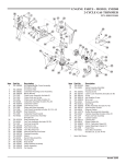
MERCARB 2 BARREL CARBURETOR
SERVICE MANUAL NUMBER 26
FUEL SYSTEM
Section 5B - MERCARB 2 BARREL CARBURETOR
Table of Contents
Identification . . . . . . . . . . . . . . . . . . . . . . . . . .
Replacement Parts Warning . . . . . . . . . . . .
Torque Specifications . . . . . . . . . . . . . . . . . .
Tools . . . . . . . . . . . . . . . . . . . . . . . . . . . . . . . .
Special Tools . . . . . . . . . . . . . . . . . . . . . . .
Specifications . . . . . . . . . . . . . . . . . . . . . . . . .
Carburetor Adjustment Specifications .
High Altitude Re-Jetting . . . . . . . . . . . . .
Important Service Information . . . . . . . . . . .
Flooding at Idle RPM . . . . . . . . . . . . . . . .
Needle/Seat Change . . . . . . . . . . . . . . . .
Adjustable Accelerator Pump Lever . . .
Description . . . . . . . . . . . . . . . . . . . . . . . . . . .
Precautions . . . . . . . . . . . . . . . . . . . . . . . . . .
Fuel Supply Connections . . . . . . . . . . . .
90-861329--1 MARCH 1999
5B-2
5B-3
5B-3
5B-3
5B-3
5B-4
5B-4
5B-5
5B-5
5B-5
5B-6
5B-6
5B-7
5B-7
5B-7
Maintenance . . . . . . . . . . . . . . . . . . . . . . . . . . 5B-8
Flame Arrestor with Carburetor Cover . 5B-8
Fuel Inlet Filter . . . . . . . . . . . . . . . . . . . . . 5B-9
Choke Inspection . . . . . . . . . . . . . . . . . . 5B-10
Adjustments . . . . . . . . . . . . . . . . . . . . . . . . . 5B-10
Pump Rod . . . . . . . . . . . . . . . . . . . . . . . . 5B-10
Choke Setting . . . . . . . . . . . . . . . . . . . . . 5B-12
Preliminary Idle Speed and Mixture . . 5B-12
Final Idle Speed and Mixture . . . . . . . . 5B-13
Repair . . . . . . . . . . . . . . . . . . . . . . . . . . . . . . 5B-15
Removal . . . . . . . . . . . . . . . . . . . . . . . . . 5B-15
Installation . . . . . . . . . . . . . . . . . . . . . . . . 5B-15
Exploded View Parts List . . . . . . . . . . . 5B-17
Disassembly . . . . . . . . . . . . . . . . . . . . . . 5B-18
Cleaning and Inspection . . . . . . . . . . . . 5B-25
Reassembly . . . . . . . . . . . . . . . . . . . . . . 5B-26
Page 5B-1
5
B
MERCARB 2 BARREL CARBURETOR
SERVICE MANUAL NUMBER 26
Identification
33049565
2301
a
b
72680
Carburetor Part Number Location
a - Part Number
b - Date Code
Data Code Explanation: Example 2301
First Figure is Year:
2 = 1992, 3 = 1993, etc.
Second Figure is Month:
2 = February, 3 = March, etc.
X = October, Y = November, Z = December
Third and Fourth Figures are Day of Month:
01 = First day, 02 = Second day, etc.
a
b
72779
Venturi Cluster Identification
a - Identification Number (See Specifications)
b - Accelerator Pump Discharge Holes
Page 5B-2
90-861329--1 MARCH 1999
MERCARB 2 BARREL CARBURETOR
SERVICE MANUAL NUMBER 26
Replacement Parts Warning
WARNING
Electrical, ignition and fuel system components on your MerCruiser are designed
and manufactured to comply with U.S. Coast Guard Rules and Regulations to minimize risks of fire and explosion.
Use of replacement electrical, ignition or fuel system components, which do not
comply with these rules and regulations, could result in a fire or explosion hazard
and should be avoided.
Torque Specifications
Description
lb-ft
Nm
Carburetor To Manifold
20
27
Fuel Line to Carburetor
18
24
Fuel Inlet Filter Nut
18
24
Tools
Part Number
Description
Tachometer
79-17391A1
Universal Carburetor Gauge
91-36392
Special Tools
Boroughs Special Tools
Description
Part Number
Boroughs Special Tool and Equipment Inc.
2429 N. Burdick Street
Kalamazoo,MI 49007
(616) 345-5163
Float Gram Scale
90-861329--1 MARCH 1999
BT 8128 B
Page 5B-3
MERCARB 2 BARREL CARBURETOR
SERVICE MANUAL NUMBER 26
Specifications
NOTICE
Unit Of Measurement: U.S. Quarts (Liters)
All capacities are approximate fluid measures.
Carburetor Adjustment Specifications
Engine Model
Carburetor Type
Carburetor Number
3.0L
MerCarb 43 mm
MerCarb 36 mm
3310-807504
1389-807505
Float Level
3/8 (10)
Spring Loaded Needle
9/16 (14) (See Note)
Float Drop
1-3/32 (27) (See Note)
Pump Rod
1-5/32 (29)
Choke Setting
Two Marks To The Lean Side
Choke Unloader
Idle Mixture Screws
5/64 [080] (2)
1-1/4 Turns
Float Weight
Factory Setting
9 Grams Maximum
Primary Jet Size
1.55 mm
1.45 mm
Power Valve Size
4 x 0.65 mm
2 x 0.60 mm
171
470
.025 (0.635)
.035 (0.89)
Venturi Cluster I.D. Number
Accelerator Pump
Discharge Hole Size
All measurements are + 1/64 in. (0.4 mm).
NOTE: Float drop measured from air horn (with gasket in place) to toe of float.
Page 5B-4
90-861329--1 MARCH 1999
MERCARB 2 BARREL CARBURETOR
SERVICE MANUAL NUMBER 26
High Altitude Re-Jetting
Engine flooding problems, at idle rpm, are generally related to the altitude (above sea level)
at which they are operated. If engine is running too rich at higher elevation, order a smaller
jet from the chart. A jet stamped “165” is a 1.65 mm jet.
Model
Carburetor
Part Number
3.0L
3310-807504
5000 ft
(1525 m)
and Below
1.55 mm
5000-9000 ft
(1525-2745 m)
1.55 mm
9000 ft
(2745 m)
and Above
1.45 mm
JET SIZES
Jet Size
Quicksilver Part Number
1.30
3302-811849
1.35
3302-811850
1.40
3302-811851
1.45
3302-9050
1.50
3302-811852
1.55
3302-811853
1.60
3302810923
1.65
3302-9058
1.70
3302-9055
1.75
3302-881854
1.80
3302-811855
1.85
3302-811856
1.90
3302-811857
Important Service Information
Flooding at Idle RPM
If your engine floods at idle rpm, check the following:
1. Problem in ignition system causing engine to run rough.
2. Idle mixture screw adjusted incorrectly.
3. Bad needle and seat.
4. Incorrect float level drop.
90-861329--1 MARCH 1999
Page 5B-5
MERCARB 2 BARREL CARBURETOR
SERVICE MANUAL NUMBER 26
Needle/Seat Change
If the preceding steps failed to correct the problem, change the needle/seat to the other type.
MerCarbs are equipped with either the solid or the spring loaded needle.
a
b
72290
Needle and Seat Assemblies
a - Spring Loaded Type Needle (Kit 3302-9029)
b - Solid Type Needle (Kit 3302-9407)
Adjustable Accelerator Pump Lever
This new 3-holed lever will allow you to change the amount of fuel delivered to the engine
by the accelerator pump. The hole closest to the lever’s shaft will give the same amount of
fuel as the single hole lever did. The center hole gives approximately 0.5 cc less fuel and
the hole farthest away will give about 1.0 cc less fuel.
a
b
c
73131
a - Full Accelerator Pump Stroke
b - 0.5 cc Less Fuel per Stroke
c - 1.0 cc Less Fuel per Stroke
The technician should be able to correct most “bogging” problems with this 3-holed lever,
providing the “bogging” is caused by the carburetor. When installing the 3-holed lever,
remove any metal ball that someone may have put in the accelerator pump well to limit pump
travel. Also, make sure that the duration spring on the accelerator pump is stock and hasn’t
had several coils cut off. Make sure the venturi cluster is the correct one as outlined
previously under “Specifications.”
Page 5B-6
90-861329--1 MARCH 1999
MERCARB 2 BARREL CARBURETOR
SERVICE MANUAL NUMBER 26
Description
This MerCarb carburetor is a two bore carburetor and has a separate fuel feed for each
venturi. This model also is equipped with an electric choke. A removable venturi cluster
(secured to float bowl assembly) has the calibrated main well tubes and pump jets built into
it. The venturi cluster is serviced as a unit. The serviceable main metering jets are bleeds
to properly meter the correct fuel/air mixture to the engine.
Precautions
WARNING
Always disconnect battery cables from battery BEFORE working on fuel system to
prevent fire or explosion.
WARNING
Be careful when cleaning flame arrestor and crankcase ventilation hose; gasoline
is extremely flammable and highly explosive under certain conditions. Be sure that
ignition key is OFF. DO NOT smoke or allow sources of spark or open flame in area
when cleaning flame arrestor and crankcase ventilation hose.
WARNING
Be careful when changing fuel system components; gasoline is extremely flammable and highly explosive under certain conditions. Be sure that ignition key is
OFF. DO NOT smoke or allow sources of spark or flame in the area while changing
fuel filter. Wipe up any spilled fuel immediately.
WARNING
Make sure no fuel leaks exist, before closing engine hatch.
Fuel Supply Connections
CAUTION
DO NOT operate engine without cooling water being supplied to water pickup holes
in gear housing, or water pump impeller will be damaged and subsequent overheating damage to engine may result.
90-861329--1 MARCH 1999
Page 5B-7
MERCARB 2 BARREL CARBURETOR
SERVICE MANUAL NUMBER 26
Maintenance
Flame Arrestor with Carburetor Cover
NOTICE
Refer to “Precautions” in this section, BEFORE proceeding.
1. Remove in the following order:
a. Nut.
b. Sealing washer.
c. Crankcase ventilation hoses from flame arrestor and rocker arm covers.
d. Flame arrestor.
2. Clean and inspect:
a. Clean flame arrestor in solvent and blow dry with compressed air.
b. Clean crankcase ventilation hoses.
c. Inspect crankcase ventilation hoses for cracks or deterioration, and replace if necessary.
3. Install in the following order:
a. Flame arrestor.
b. Crankcase ventilation hoses to flame arrestor and rocker arm covers.
c. Sealing washer.
d. Nut (tighten securely).
a
b
c
c
d
72086
a
b
c
d
Page 5B-8
- Nut
- Sealing Washer
- Crankcase Ventilation Hose
- Flame Arrestor
90-861329--1 MARCH 1999
MERCARB 2 BARREL CARBURETOR
SERVICE MANUAL NUMBER 26
Fuel Inlet Filter
NOTICE
Refer to “Precautions” in this section, BEFORE proceeding.
1. Remove in the following order:
a. Fuel line from fuel inlet filter nut.
b. Fuel inlet filter nut and small gasket.
c. Large gasket.
d. Filter.
e. Spring.
f.
Small gasket - from inside filter nut.
b
c d
e
f
a
72406
a
b
c
d
e
f
- Fuel Line
- Fuel Inlet Filter Nut
- Gasket (Large)
- Gasket (Small)
- Filter
- Spring
2. Clean filter nut and spring in solvent and dry with compressed air.
3. Install in the following order:
a. Spring - place in carburetor body.
b. Filter - open end to inlet filter nut.
c. Small gasket - place inside filter nut.
d. Large gasket - place over filter nut threads.
e. Fuel inlet filter nut - torque nut to 18 lb-ft (24 Nm).
f.
90-861329--1 MARCH 1999
Fuel line - torque to 18 lb-ft (24 Nm).
Page 5B-9
MERCARB 2 BARREL CARBURETOR
SERVICE MANUAL NUMBER 26
Choke Inspection
The choke does not require any periodic maintenance; however, if a choke malfunction is
suspected, the following should be done:
1. With engine turned OFF, remove flame arrestor.
2. Open and close choke several times, and check for binding, loose or disconnected
linkages, or other signs of damage.
3. If choke or linkage binds, sticks, or works sluggishly, clean with carburetor choke
cleaner. Follow directions on can.
IMPORTANT: Choke valve and shaft and lever assembly is not serviceable. If valve
and/or shaft and lever assembly is worn or damaged, air horn assembly must be
replaced.
Adjustments
NOTICE
Refer to “Precautions” in this section, BEFORE proceeding.
Pump Rod
1. Loosen idle speed screw until it no longer contacts idle cam.
b
a
72284
a - Idle Speed Screw
b - Idle Cam
Page 5B-10
90-861329--1 MARCH 1999
MERCARB 2 BARREL CARBURETOR
SERVICE MANUAL NUMBER 26
2. With throttle valves completely closed, measure from flame arrestor mounting surface
to top of pump rod.
a
72682
a - See Specifications
3. Carefully bend pump rod (where shown) to obtain specified dimension.
a
b
72683
a - Pump Rod
b - Bend Here
90-861329--1 MARCH 1999
Page 5B-11
MERCARB 2 BARREL CARBURETOR
SERVICE MANUAL NUMBER 26
Choke Setting
Normal choke setting is such that scribed mark on cover is in line with long case mark on
choke housing.
a
c
b
72403
a - Scribed Mark
b - More Choke
c - Less Choke
If choke adjustment is necessary:
1. Loosen three choke cover retaining screws and adjust as shown.
2. Tighten three choke cover retaining screws securely.
Preliminary Idle Speed and Mixture
IMPORTANT: The following adjustments will provide a sufficient idle speed and mixture for starting engine. Final adjustments must be made with engine running.
1. Back out idle speed screw until it no longer contacts idle cam. Turn idle speed screw in
until it just contacts idle cam, then turn screw in an additional two turns.
b
a
72284
a - Idle Speed Screw
b - Idle Cam
IMPORTANT: DO NOT turn idle mixture needle tightly against seat (in the following
step), as damage to seat and/or needle may result.
Page 5B-12
90-861329--1 MARCH 1999
MERCARB 2 BARREL CARBURETOR
SERVICE MANUAL NUMBER 26
2. Turn idle mixture needle in until lightly seated, then back needle out 1-1/4 turns.
a
72281
a - Idle Mixture Needle
Final Idle Speed and Mixture
EMISSIONS CARBURETOR
Sealed Carburetor Mixture Screw
The carburetor on this engine has a seal on the carburetor mixture screw. This seal prevents
adjustment of the fuel mixture setting.
CAUTION
Do not remove mixture screw seal and/or attempt to adjust fuel mixture setting.
Tampering with the mixture setting on this engine could affect the exhaust
emissions level, thus voiding the emissions certification. This seal should only be
removed by an authorized dealer or emissions testing agency.
NON-EMISSIONS CARBURETOR
IMPORTANT: Boat must be in the water and engine at normal operating temperature
to accurately check and adjust idle speed and mixture.
Carburetor should be set so that engine idles smoothly within range given under “Specifications,” with boat in the water, engine at normal operating temperature and drive unit in forward gear. To adjust idle speed and mixture, proceed as follows:
IMPORTANT: DO NOT attempt to compensate for other engine problems (incorrect
ignition timing, faulty ignition components, low compression, vacuum leaks, etc.)
with carburetor adjustments. This will only cover the problem, which must be corrected if engine is to achieve maximum fuel economy and performance.
1. Connect an accurate shop tachometer to engine.
IMPORTANT: DO NOT turn idle mixture needle tightly into seat, as damage to needle
and/or seat may result.
a
72281
a - Idle Mixture Needle
90-861329--1 MARCH 1999
Page 5B-13
MERCARB 2 BARREL CARBURETOR
SERVICE MANUAL NUMBER 26
2. If new or rebuilt carburetor has been installed, turn idle mixture needle in (clockwise)
until it lightly contacts seat, then back out needle 1-1/4 turns. This will provide a sufficient
setting to allow starting engine.
3. Start engine and run at 1500 rpm until engine reaches normal operating temperature.
WARNING
DO NOT leave the helm unattended while performing idle speed and mixture adjustments, following. BE CAREFUL NOT TO ACCIDENTALLY ACCELERATE ENGINE
WHILE PERFORMING ADJUSTMENTS.
4. With boat in open water, place remote control in forward gear, idle position.
5. Disconnect throttle cable barrel from anchor stud. Be sure not to lose spacer on anchor
stud.
6. Adjust idle speed adjustment screw to obtain 550-600 rpm, in neutral gear.
7. With engine running at specified rpm, adjust idle mixture needle as follows:
a. Turn idle mixture needle in (clockwise) until the engine speed begins to drop due to
lean mixture.
b. Turn idle mixture screw out (counterclockwise) until the speed begins to drop due
to rich mixture.
c. Turn screw in to a point between these two extremes to obtain maximum engine
smoothness and rpm.
d. Readjust idle speed adjustment screw until engine idles at 650-700 rpm in forward
gear.
IMPORTANT: Refer to Section 2 “Removal and Installation” for throttle cable installation and adjustment.
Page 5B-14
90-861329--1 MARCH 1999
MERCARB 2 BARREL CARBURETOR
SERVICE MANUAL NUMBER 26
Repair
NOTICE
Refer to “Precautions” in this section, BEFORE proceeding.
Removal
IMPORTANT: Carburetor malfunctions are, in many cases, caused by the presence
of dirt, water or other foreign matter in carburetor. To aid in diagnosis, carefully
remove carburetor from engine without draining fuel from bowl. Contents of fuel
bowl may then be inspected for contamination as carburetor is disassembled.
1. Remove ventilation hose from flame arrestor, then remove flame arrestor.
IMPORTANT: Place a clean cloth in bores of carburetor to prevent dirt and foreign
material from falling into bores.
2. Turn fuel supply off at fuel tank.
3. Disconnect throttle cable from carburetor.
4. Remove fuel line from fuel inlet nut, using wrench to stabilize fuel inlet nut.
5. Remove fuel pump sight tube from carburetor.
6. Disconnect electric choke.
7. Remove carburetor attaching nuts and washers and remove carburetor.
IMPORTANT: Place a clean cloth over intake manifold opening to prevent dirt or foreign material from entering manifold.
8. Remove and discard gaskets.
Installation
1. Thoroughly clean gasket surfaces.
2. Place new carburetor base gasket on intake manifold. Install carburetor and secure with
nuts and washers. Torque to 132 lb-in. (15 Nm).
3. If fuel inlet filter nut was disturbed, remove; clean all threads with brush and carburetor
cleaner or Quicksilver Leveler.
4. Connect fuel line to fuel inlet filter nut, and while stabilizing filter nut with wrench, tighten
fuel line fitting securely.
5. Connect fuel pump sight tube to fitting on carburetor.
6. Connect electric choke wires to choke cover.
7. Install throttle cable as explained in SECTION 2.
8. Install flame arrestor and crankcase ventilation hose.
9. Reconnect battery cables to battery.
10. Ensure that water is supplied to cooling system. Start engine and check for gasoline
leaks. If leaks exist, STOP ENGINE IMMEDIATELY and recheck connections.
11. Adjust idle speed and idle mixture, as outlined under “Adjustments” as previously outlined.
90-861329--1 MARCH 1999
Page 5B-15
MERCARB 2 BARREL CARBURETOR
SERVICE MANUAL NUMBER 26
72686
Page 5B-16
90-861329--1 MARCH 1999
SERVICE MANUAL NUMBER 26
MERCARB 2 BARREL CARBURETOR
Exploded View Parts List
1 - Rod - Accelerator Pump
2 - Accelerator Pump Shaft and Lever
Assembly
3 - Washer (Outer)
4 - Washer (Inner)
5 - Screw
6 - Washer
7 - Screw
8 - Spring
9 - Filter
10 - Gasket
11 - Gasket
12 - Nut-Fuel Inlet
13 - Choke-Rod
14 - Gasket
15 - Clip - Retainer
16 - Washer
17 - Pump Shaft and Lever Assembly
18 - Accelerator Pump Assembly
19 - Spring
20 - Screw
21 - Inlet Needle and Seat (Spring
Loaded - Optional)
22 - Baffle Plate
23 - Float
24 - Float Bowl
25 - Cam-Idle
26 - Screw
27 - Idle Mixture Adjusting Needle
28 - Spring
29 - Washer
30 - Nut
90-861329--1 MARCH 1999
31 - Clip-Pump Rod
32 - Washer-Locking
33 - Nut
34 - Throttle Lever
35 - Spring
36 - Screw - Idle Speed Adjustment
37 - Throttle Body
38 - Screw
39 - Washer
40 - Gasket
41 - Check Ball
42 - Spring
43 - Retainer
44 - Screw
45 - Lever Assembly
46 - Screw
47 - Choke/Housing
48 - Gasket
49 - Air Horn
50 - Inlet Needle And Seat
51 - Pin
52 - Screw
53 - Gasket
54 - Screw
55 - Screw
56 - Flat Washer
57 - Lock Washer
58 - Gasket
59 - Venturi Cluster
60 - Power Valve Assembly
61 - Gasket
62 - Gasket
Page 5B-17
MERCARB 2 BARREL CARBURETOR
SERVICE MANUAL NUMBER 26
Disassembly
The following is a step-by-step procedure for completely overhauling carburetor removed
from engine. In many cases, however, complete overhaul is not necessary and, in these
cases, only the steps required to repair the carburetor malfunction should be performed.
Read the instructions carefully to prevent doing any unnecessary steps.
IMPORTANT: Before performing any service on carburetor, it is essential that carburetor be placed in a holding fixture to prevent possible damage to throttle valves.
CHOKE HOUSING ASSEMBLY
1. Remove choke cover.
a
72403
a - Choke Cover
2. Remove choke lever. Remove choke housing.
a
b
72401
a - Choke Lever
b - Choke Housing
Page 5B-18
90-861329--1 MARCH 1999
MERCARB 2 BARREL CARBURETOR
SERVICE MANUAL NUMBER 26
AIR HORN ASSEMBLY
1. Remove fuel inlet filter nut, washers, spring, and filter, as outlined previously.
2. Remove accelerator pump rod retaining clip. Pivot rod (as required) until retaining ear
on rod and slot in pump shaft and lever assembly align, allowing rod to be pulled out.
c
a
b
72283
a - Accelerator Pump Rod
b - Retainer Clip
c - Pump Shaft and Lever Assembly
3. Remove idle cam screw. Also, remove choke rod by pivoting rod (as required) until
retaining ear on rod and slot in choke lever align, allowing rod to be pulled out.
c
b
a
72282
a - Idle Cam Screw
b - Idle Cam
c - Choke Rod
90-861329--1 MARCH 1999
Page 5B-19
MERCARB 2 BARREL CARBURETOR
SERVICE MANUAL NUMBER 26
4. Remove air horn attaching screws as shown.
a
a
a
a
72280
a - Air Horn Attaching Screws
5. Carefully lift air horn from float bowl assembly.
a
b
72400
a - Air Horn Assembly
b - Float Bowl Assembly
6. Invert air horn and carefully lay on bench.
7. Remove float hinge pin and lift float assembly from air horn.
b
a
72288
a - Float Hinge Pin
b - Float Assembly
Page 5B-20
90-861329--1 MARCH 1999
MERCARB 2 BARREL CARBURETOR
SERVICE MANUAL NUMBER 26
8. Check float weight as shown.
a
b
72122
a - Grams Scale
b - Float
9. Remove air horn gasket and baffle.
b
72399
a
a - Baffle
b - Air Horn Gasket
10. Remove needle assembly.
a
b
72287
a - Needle Assembly
b - Needle Seat
90-861329--1 MARCH 1999
Page 5B-21
MERCARB 2 BARREL CARBURETOR
SERVICE MANUAL NUMBER 26
11. Remove needle seat.
c
a
b
72289
a - Needle Seat
b - Gasket
c - Screwdriver
a
b
72290
Needle and Seat Assemblies
a - Spring Loaded Type Needle (Kit 3302-9029)
b - Solid Type Needle (Kit 3302-9407)
12. Loosen accelerator pump screw. Slide pump shaft and lever assembly (and washer) out
of air horn, then remove accelerator pump assembly.
b
a
c
72398
a - Setscrew
b - Lever Assembly
c - Pump Assembly
Page 5B-22
90-861329--1 MARCH 1999
MERCARB 2 BARREL CARBURETOR
SERVICE MANUAL NUMBER 26
13. Remove retainer clip and washer from pump shaft and lever assembly, then remove
accelerator pump assembly.
b
c
a
72409
a - Pump Assembly
b - Retainer Clip
c - Lever Assembly
FLOAT BOWL ASSEMBLY
1. Remove accelerator pump return spring from pump well.
a
72402
a - Accelerator Pump Spring
2. Remove power valve assembly and gasket.
a
b
72404
a - Power Valve Assembly
b - Gasket (Not Shown)
90-861329--1 MARCH 1999
Page 5B-23
MERCARB 2 BARREL CARBURETOR
SERVICE MANUAL NUMBER 26
3. Remove main metering jets.
a
b
b
72291
a - Main Metering Jets
b - Gaskets (Not Shown)
IMPORTANT: Use care when removing venturi cluster to prevent damaging brass
tubes which protrude from bottom of cluster. DO NOT REMOVE TUBES. These tubes
are permanently pressed into the venturi cluster and are not replaceable.
4. Remove three venturi cluster screws, and carefully lift cluster and venturi gasket straight
up.
a
b
72292
a - Venturi Cluster Brass Tubes
b - Gasket
5. Using needle-nose pliers, remove accelerator pump check ball spring retainer. Turn
float bowl over to remove spring and check ball.
a
b
72407
a - Spring Retainer
b - Spring and Check Ball (Not Shown)
Page 5B-24
90-861329--1 MARCH 1999
MERCARB 2 BARREL CARBURETOR
SERVICE MANUAL NUMBER 26
Cleaning and Inspection
IMPORTANT: DO NOT use a wire or drill to clean jet passages or tubes in carburetor,
as this may enlarge orifices and seriously affect carburetor calibration.
CAUTION
To avoid damage to carburetor DO NOT leave carburetor in immersion type carburetor cleaner for more than two hours.
IMPORTANT: DO NOT clean float bowl gasket surfaces with a gasket scraper or knife,
as sealing bead will be damaged and float bowl replacement will be necessary.
CAUTION
The float assembly, float needle, accelerator pump plunger, and fuel filter MUST
NOT BE immersed in carburetor cleaner, as they will swell, harden, and/or distort.
b
c
a
d
a
b
c
d
72410
- Accelerator Pump Plunger
- Float Needle
- Fuel Filter
- Float Assembly
WARNING
Avoid personal injury by always wearing safety goggles when using compressed
air.
1. Thoroughly clean all metal parts in a commercial carburetor cleaner, until all deposits
have been removed. Follow cleaner manufacturer’s instructions for proper cleaning and
rinsing procedure. Dry parts with compressed air.
2. Using compressed air, blow out all passages in carburetor to remove any foreign
material.
3. Wipe off all parts that cannot be cleaned in carburetor cleaner with a clean, dry cloth.
4. Carefully inspect all carburetor parts for wear and damage; pay particular attention to
the following:
a. Float Needle and Seat: If float needle or seat is worn or damaged, replace with new
needle and seat assembly.
IMPORTANT: Float needle and seat are factory matched and tested and should be
replaced as a set only.
b. Float Assembly and Hinge Pin: Check float density (to see if it is saturated with
fuel) by comparing weight of float with specifications. If weight is high, float assembly
must be replaced. Check hinge pin and holes for wear.
90-861329--1 MARCH 1999
Page 5B-25
MERCARB 2 BARREL CARBURETOR
SERVICE MANUAL NUMBER 26
c. Fuel and Air Passages: Passages must be perfectly clean for proper carburetor
operation.
d. Accelerator Pump Plunger and Return Spring: Inspect pump plunger cup, pump
plunger spring (on pump assembly) and return spring.
e. Power Piston Spring: Check power piston spring for weakness or distortion.
f.
Idle Mixture Needle: Inspect idle mixture needle. If damaged, needle must be
replaced.
g. Levers and Linkages: Check levers, links and rods for wear.
h. Throttle Valve and Shaft: Check throttle shaft for excessive looseness in throttle
body. Check throttle valve and shaft for binding through entire operating range,
making sure valve opens and closes completely. Throttle body assembly must be
replaced if throttle valve and shaft are worn or damaged.
i.
Choke Valve and Shaft and Lever Assembly: Check shaft and lever assembly for
excessive looseness in air horn assembly. Check choke valve and shaft and lever
assembly for binding through entire operating range, making sure valve opens and
closes completely. Air horn assembly must be replaced if choke valve and shaft and
lever assembly are worn or damaged.
j.
Inspect Casting for visible damage. Inspect gasket surfaces. Inspect accelerator
pump plunger well for scoring or deposits.
Reassembly
IMPORTANT: DO NOT force idle mixture needle against seat as damage to needle
and/or seat will result.
FLOAT BOWL ASSEMBLY
IMPORTANT: Place float bowl and throttle assemblies in holding fixture to prevent
throttle valves from being damaged.
1. Install check ball, spring, and retainer in passage as shown. Push retainer firmly into
slots.
c
b
a
72408
a - Check Ball
b - Spring
c - Retainer
Page 5B-26
90-861329--1 MARCH 1999
MERCARB 2 BARREL CARBURETOR
SERVICE MANUAL NUMBER 26
2. Install new gasket on venturi cluster as shown.
b
a
72296
a - Venturi Cluster (I.D. No. 421)
b - Gasket
3. Install venturi cluster in carburetor as shown.
b
a
72397
a - Venturi Cluster
b - Gasket
4. Install flat washer and new fiber washer on center screw. Lockwashers and flat washers
are used on outer screws. Tighten screws evenly and securely.
a
b
b
c
72405
a - Center Screw
b - Outside Screws
c - Fiber Washer
90-861329--1 MARCH 1999
Page 5B-27
MERCARB 2 BARREL CARBURETOR
SERVICE MANUAL NUMBER 26
5. Install main metering jets with gaskets as shown. Tighten securely.
a
b
b
72291
a - Main Metering Jets
b - Gaskets (Not Shown)
6. Install power valve with new gasket. Tighten securely.
b
a
72404
a - Power Valve
b - Gasket (Not Shown)
7. Place accelerator pump spring in pump well.
a
72402
a - Accelerator Pump Spring
Page 5B-28
90-861329--1 MARCH 1999
MERCARB 2 BARREL CARBURETOR
SERVICE MANUAL NUMBER 26
AIR HORN ASSEMBLY
IMPORTANT: Accelerator pump assembly MUST BE installed correctly. If pump
assembly is installed incorrectly, top of pump assembly will contact air horn casting.
1. If accelerator pump assembly was removed from pump lever, secure pump assembly
to pump lever with washer and retainer clip, as shown.
c
b
a
72409
a - Pump Assembly
b - Retainer Clip
c - Pump Lever
2. Insert pump shaft and lever assembly (and washer) into air horn; then, align indexed
hole in pump lever with shaft and lever assembly and slide shaft all the way into lever
so that shoulder on shaft is hitting lever. Tighten setscrew securely.
a
b
c
72398
a - Setscrew
b - Lever Assembly
c - Pump Assembly
90-861329--1 MARCH 1999
Page 5B-29
MERCARB 2 BARREL CARBURETOR
SERVICE MANUAL NUMBER 26
3. Install needle seat and gasket. Tighten securely.
c
a
b
72289
a - Needle Seat
b - Gasket
c - Screwdriver
IMPORTANT: Float needle and needle seat are factory matched and tested and
should be replaced as a set only.
4. Place needle assembly in needle seat.
a
b
72287
a - Needle Assembly
b - Needle Seat
5. Install baffle and gasket.
72399
b
a
a - Baffle
b - Gasket
Page 5B-30
90-861329--1 MARCH 1999
MERCARB 2 BARREL CARBURETOR
SERVICE MANUAL NUMBER 26
6. Install float assembly and hinge pin. Pivot float assembly up and down on hinge pin to
ensure it moves freely.
b
a
72297
a - Float Assembly
b - Float Hinge Pin
FLOAT LEVEL
1. Turn air horn upside down. Pivot float assembly up and down on hinge pin to ensure it
moves freely.
IMPORTANT: Before checking float level, raise float and allow it to fall; however, DO
NOT force downward by hand.
2. Measure float level using Universal Carburetor Gauge (91-36392). Measure from gasket to toe of float.
a
72298
a - Measure from This Point to Gasket
a
72687
a - Measurement With 2 Piece Solid Inlet Needle - 3/8 in. (10 mm)
b - Measurement With Spring Loaded Inlet Needle - 9/16 in. (14 mm)
90-861329--1 MARCH 1999
Page 5B-31
MERCARB 2 BARREL CARBURETOR
SERVICE MANUAL NUMBER 26
3. Bend float arm up or down at point shown to obtain specified dimension.
a
72688
a - Bend Float Arm at This Point
4. Visually check float alignment after adjustment.
FLOAT DROP
1. Hold air horn right side up to allow float to hang free.
2. Measure float drop using Universal Carburetor Gauge (91-36392). Measure from gasket to toe of float.
a
72689
a - Measurement - 1-3/32 in. (27 mm)
3. Bend float assembly tang, as shown, to obtain specified dimension.
a
72690
a - Float Assembly Tang
Page 5B-32
90-861329--1 MARCH 1999
MERCARB 2 BARREL CARBURETOR
SERVICE MANUAL NUMBER 26
4. Recheck BOTH float level and float drop.
5. Carefully place air horn on float bowl, making sure accelerator pump is correctly positioned in fuel well. Lower air horn straight down to install.
a
b
72400
a - Air Horn Assembly
b - Float Bowl Assembly
6. Install seven short and one long air horn attaching screws. Tighten screws evenly and
securely.
a
a
a
72280
a
a - Air Horn Attaching Screws
7. Place end of choke rod in choke lever and collar assembly.
a
b
72299
a - Choke Rod
b - Choke Lever and Collar Assembly
90-861329--1 MARCH 1999
Page 5B-33
MERCARB 2 BARREL CARBURETOR
SERVICE MANUAL NUMBER 26
8. Place idle cam on choke rod.
a
b
72392
a - Idle Cam
b - Choke Rod
9. Secure idle cam (with choke rod installed on cam) on float bowl assembly, using screw.
Check that cam is free to move without binding.
c
b
a
72282
a - Screw
b - Idle Cam
c - Choke Rod
10. Place accelerator pump rod (end with ear) in hole in pump shaft and lever assembly.
a
b
72393
a - Accelerator Pump Rod
b - Pump Shaft and Lever Assembly
Page 5B-34
90-861329--1 MARCH 1999
MERCARB 2 BARREL CARBURETOR
SERVICE MANUAL NUMBER 26
11. Insert remaining end of accelerator pump rod into hole in throttle lever and secure with
retainer clip.
a
b
c
72283
a - Accelerator Pump Rod
b - Throttle Lever
c - Retainer Clip
CHOKE HOUSING ASSEMBLY
1. Install choke housing on air horn; tighten screws securely. Install choke lever; tighten
screw securely.
c
b
a
72401
a - Choke Housing
b - Choke Housing Attaching Screws
c - Choke Lever
2. Install choke cover. Make sure hook on end of choke coil engages with choke lever.
Rotate choke cover until index marks align as shown. Tighten screws securely.
a
c
b
72403
a - Scribed Mark
b - More Choke
c - Less Choke
90-861329--1 MARCH 1999
Page 5B-35