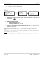
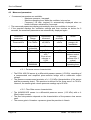
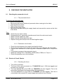
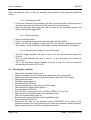
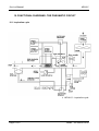
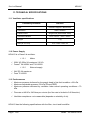
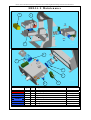
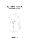
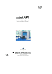
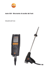
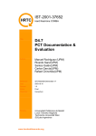
1
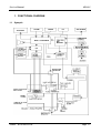
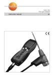
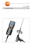
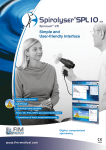
SAIME Fabricant de Matériel Médical Medical Device Manufacturer HELIAHELIA-S PRESSURE SUPPORT PULMONARY VENTILATOR Service Manual Ref. NTA0005042-b SAIME S.A. - 25, rue de l’étain - 77176 Savigny-le-Temple Tél. : 01 64 19 11 11 - Fax : 01 64 41 81 30 Service Manual HELIA-S WARNING ➫ This Service Manual may be used as a complement of Helia User’s Manual. It is therefore compulsory to have read and understood the User’s Manual prior to the lecture and understanding of the Service Manual. ➫ Helia S settings should be made by professionally trained and competent personnel working under a doctor’s responsibility. ➫ Helia S settings exclusively depend on a doctor’s medical prescription. Page II SAIME – NTA0005042-b Service Manual HELIA-S Contents 1. FUNCTIONAL DIAGRAM _____________________________________ 1-1 1.1 Synoptic ............................................................................................. 1-1 1.2 Synoptic translation............................................................................ 1-2 2. OPERATING PRINCIPAL_____________________________________ 2-4 2.1 Principle ............................................................................................. 2-4 2.2 Microcontroller ................................................................................... 2-4 2.3 Current supply possibilities ................................................................ 2-4 3. OXYGEN SUPPLY REMINDER ________________________________ 3-6 4. VENTILATION SETTINGS REMINDER __________________________ 4-7 4.1 Ventilation settings chart.................................................................... 4-7 4.2 Delivered minute volume ................................................................... 4-7 4.3 Measured parameters........................................................................ 4-8 4.3.1 Pressure sensor characteristics ............................................. 4-8 4.3.2 Flow Rate sensor characteristics............................................ 4-8 4.3.3 Measuring the inspiratory volume control............................... 4-9 5. ALARMS _________________________________________________ 5-10 5.1 Automatic not adjustable alarms. ..................................................... 5-10 5.1.1 Low Pressure Alarm ............................................................. 5-10 5.1.2 High Pressure Alarm ............................................................ 5-10 5.2 Adjustable alarms ............................................................................ 5-10 5.3 Signalling alarms.............................................................................. 5-10 5.4 Alarms operation.............................................................................. 5-11 5.4.1 Mains.................................................................................... 5-11 5.4.2 External supply..................................................................... 5-11 5.5 Alarms - Summary table .................................................................. 5-12 SAIME – NTA0005042-b Page III Service Manual HELIA-S 6. CLEANING AND STERILISING _______________________________ 6-14 6.1 6.2 6.3 6.4 6.5 Maintenance frequency.................................................................... 6-14 Patient circuit ................................................................................... 6-14 Bacteria filter.................................................................................... 6-14 External unit parts ............................................................................ 6-14 Heating chamber.............................................................................. 6-15 7. MAINTENANCE AND PREVENTIVE INSPECTIONS ______________ 7-16 8. CHECKING THE VENTILATOR _______________________________ 8-17 8.1 Checking the pneumatic circuit ........................................................ 8-17 8.1.1 The pneumatic block ............................................................ 8-17 8.1.2 Pneumatic circuit tubes ........................................................ 8-17 8.2 Electrical Circuit Checks .................................................................. 8-17 8.2.1 Checking the fuses............................................................... 8-17 8.2.2 Checking the LED ................................................................ 8-18 8.2.3 Electrical wiring .................................................................... 8-18 8.2.4 Checking the voltages on the CPU board ............................ 8-18 10.3 Checking the Alarms................................... Erreur ! Signet non défini. 9. ADJUSTING THE VENTILATOR SETTINGS_____________________ 9-20 9.1 Technical Access ............................................................................. 9-20 9.1.1 To access the technical menu .............................................. 9-20 9.1.2 To leave the technical menu................................................. 9-20 9.2 Adjusting the Sensors ...................................................................... 9-20 9.3 Adjusting the pressure (DIV.P) ........................................................ 9-20 9.4 Adjusting the Peep compressor ....................................................... 9-21 9.5 Adjusting the inspiratory volume ...................................................... 9-21 9.6 Adjusting the display contrast .......................................................... 9-21 10. FUNCTIONAL DIAGRAMS: THE PNEUMATIC CIRCUIT __________ 10-22 10.1 Inspiration cycle ............................................................................. 10-22 10.2 Expiration cycle.............................................................................. 10-24 11. TECHNICAL SPECIFICATIONS______________________________ 11-26 11.1 Ventilator specifications ................................................................. 11-26 Page IV SAIME – NTA0005042-b Service Manual HELIA-S 11.2 Power Supply................................................................................. 11-26 11.2.1 Mains ................................................................................. 11-26 11.2.2 External supply .................................................................. 11-26 11.3 Performances ................................................................................ 11-26 11.4 Conditions of use ........................................................................... 11-27 11.5 Ventilator operating limits............................................................... 11-27 11.6 Storage conditions ......................................................................... 11-28 11.6.1 The ventilator and its accessories are in original boxes..... 11-28 11.6.2 The ventilator and its accessories are not in original boxes11-28 11.7 Transport conditions ...................................................................... 11-28 11.8 Materials used................................................................................ 11-28 11.9 Fire prevention ............................................................................... 11-28 11.10 Applied Standards ................................................................... 11-29 12. TECHNICAL SPECIFICATIONS FOR THE VENTILATOR ACCESSORIES __________________________________________ 12-30 12.1 12.2 12.3 12.4 12.5 12.6 12.7 Pneumatic circuits.......................................................................... 12-30 Gas input filter................................................................................ 12-30 Bacteria filter.................................................................................. 12-30 Oxygen supply ............................................................................... 12-30 Heating chambers.......................................................................... 12-31 External DC Power Supply ............................................................ 12-31 Technical properties of BACTINYL 5M ....................................... 12-31 12.7.1 Instructions for use............................................................. 12-31 12.7.2 Caution............................................................................... 12-31 Appendix 1 : Applicable Diagrams _____________________________ 12-33 Appendix 2: Symbols ________________________________________ 12-35 SAIME – NTA0005042-b Page V Service Manual HELIA-S 1. FUNCTIONAL DIAGRAM 1.1 Synoptic SAIME – NTA0005042-b Page 1-1 Service Manual 1.2 HELIA-S Synoptic translation Afficheur Air ambiant Alimentation continue Alimentation extérieure Alimentation Secteur Alimentation secteur carte BLOC SOUPAPE Capteur de débit expiratoire Capteur de débit inspiratoire Capteur de Pression Capteur de Pression DCAL 430 Capteur débit Capteur Oxygène Carte alimentation Carte CPU Carte FDC Chambre expiratoire Chambre inspiratoire Clapet anti-retour Clavier CNA Codeur Comande moteur Command de valve expiratoire Compresseur CYN Electrovanne Electrovanne Dépression Electrovanne Expiratoire Electrovanne Inspiratoire Entree des gas Entree Oxygène Expiration Extérieur Filtre poussière Fuite ajustable Fuite calibrée Fusible Inspiration Insufflation Mesure débit expiratoire Mesure débit inspiratoire Mesure Oxygène Mesure Pression Moteur Regulateur PEEP Page 1-2 Display Ambient air Continuous DC external supply External power supply Mains supply PWR card mains supply VALVE UNIT Exhale rate sensor Inhale rate sensor pressure sensor DCAL 430 pressure sensor Flow rate sensor Oxygen sensor Power supply board CPU board FDC board Exhale chamber Inhale chamber Non-return valve Keyboard CNA Coder Motor control Exhale valve control Compressor CYN Electro valve Volume drop electro valve Exhale electro valve Inhale electro valve Gas input Oxygen input Exhale circuit Outside Dust filter Adjustable vent Calibrated Vent Fuse Inhale direction Insufflation toward patient Exhale rate measurement Inhale rate measurement Oxygen measuring cell pressure measurement Motor PEEP regulator SAIME – NTA0005042-b Service Manual Retour Expiration patient Secteur Selection des tensions Sélection pression débit Sortie des Gaz expirés Sortie insufflation vers patient Transformateur Turbine Turbine Moteur MINIMOTOR Valve Valve expiratoire Ventilateur SAIME – NTA0005042-b HELIA-S Patient exhale return Mains Voltage selector Flow rate pressure selector Exhaled gas output Insufflation output toward the patient Transformer Supply Head Supply Head / Minimotor motor Valve Exhale Valve Ventilator Page 1-3 Service Manual HELIA-S 2. OPERATING PRINCIPAL 2.1 Principle ! The pneumatic system is based on a supply head and pneumatic block. ! The supply head is driven by a brushless DC motor. The supply sucks in the surrounding air and passes it through a filter. The pneumatic block either distributes the air to the patient (the insufflation cycle) or else blocks off the gas during the expiration cycle. ! The pressure delivered by the ventilator during the inhale cycle depends on the rotation speed of the supply head. ! The Positive End Expiratory Pressure (PEEP) is determined via a compressor and a pneumatic regulator. ! Non-return safety valves ensure that the patient can breath freely through the ventilator. 2.2 Microcontroller The microcontroller on the Central Processing Unit (CPU) manages: ! The ventilation cycles (frequencies, inspiration times..) by means of the inhale and exhale electrovalves. ! The pressure level by means of the supply head and pressure sensor readings. ! The Positive End Expiratory Pressure (PEEP) by means of the compressor. ! The inhale trigger by means of the pressure sensor. ! The exhale trigger (PSV & PSV+F modes) by means of the inhale flow rate sensor (pressure loss type sensor) ! Man/machine interface communication (keyboard, LED, display, etc.) ! The alarms (buzzer) ! Power supply source switching 2.3 Current supply possibilities ! The Helia S may be run either from: - the mains (230 AC – 50 Hz – 1.25 A maximum) - an external DC supply between 24 VDC / 2A maximum. ! The V.EXT LED indicates the presence of the external voltage. Note: The two sources may be connected simultaneously in which case the ventilator will default to the mains supply. Warning The Helia S has no internal battery. It is wholly dependent on the mains and/or the external DC supply. With none of those power sources, Helia S stops working. However, an audible alarm is released in such case. Page 2-4 SAIME – NTA0005042-b Service Manual HELIA-S ! Both Power Sources fail If both of these fail, an alarm warns the user that the ventilator has stopped working. This alarm is turned off by pressing the Alarm Off button. ! The DC supply fails If the DC supply fails (but the mains keeps running) an alarm goes on and a “EXT PWR!” message is displayed. This alarm is turned off by pressing the Alarm Off button. ! The mains supply fails If the mains supply fails (but the DC power keeps running) an alarm goes on and a “MAINS!” message is displayed. This alarm is turned off by pressing the Alarm Off button. # NOTE: The external power supply must have a runtime of at least one hour. SAIME – NTA0005042-b Page 2-5 Service Manual HELIA-S 3. OXYGEN SUPPLY REMINDER Synoptic Oxygen source : Wall, bottle, oxygen concentrator, liquid oxygen 100 kPa max. Flowmeter 0 to 10 L/min HELIA-S oxygen input: 100 kPa max. 10 L/min max. ! Oxygen source must be connected to the oxygen input identified on the front face by the symbol: ! Oxygen source shall provide: - maximum pressure: 100kPa - maximum adjustable flow: 10 L/min ! Accessory: Grooved on-line female coupler (diameter 4mm – ref: PMC17-02 CPC coupler) ref COU006231. Note 1: with a maximum oxygen flow of 10 L/min, Helia S can accept FiO2 from 21 to 70%. Note 2: Helia S does not feature any oxygen monitoring system. Oxygen concentration is regulated by an external flowmeter. Warning: if the oxygen pressure is higher than 1 bar, a pressure reducer must be used. Page 3-6 SAIME – NTA0005042-b Service Manual HELIA-S 4. VENTILATION SETTINGS REMINDER 4.1 Ventilation settings chart Adjustment Adjustment range increment Settings Display precision Control precision Ventilation modes PSV PSV PCV APCV Notes +F PS 05 to 60hPa 1 hPa 1hPa ±0,54 hPa Yes Yes Yes Yes PEEP 00 - 03 to 12hPa 1 hPa 1hPa ±1 hPa Yes Yes Yes Yes FREQ 05 to 60 1 1 ±10 ms Yes No Yes Yes Set to “SV” for spontaneous ventilation Set to « CV » in PCV mode cycles/min TRIGGER 01 to 10 1 1 ±0,54 hPa Yes Yes No Yes FIN.I 05 to 90% or «AUTO» 1% 1% ±5 % Yes Yes No No Tins 0,5 to 3,5s 0,1 s 0,1 s ±20 ms No No Yes Yes SLOPE 00 to 02 1 1 without Yes Yes Yes Yes 4.2 Delivered minute volume The minute volume delivered to the patient by the ventilator depends on the ventilator settings (Pressure level, Frequency, Inspiratory time) and the physiological traits of the patient (resistance & compliance). With PS=40hPa et a measured I/E=1/2, results are: Compliance Minute volume delivered for a resistance calibrated Rp20 (2,0 cm H2O/litre/s) Minute volume delivered for a resistance calibrated Rp5 (0,5 cm H2O/litre/s) 0,03 L/cm H2O 23 litres 43 litres 0,04 L/cm H2O 24 litres 44 litres 0,05 L/cm H2O 24 litres 45 litres 0,06 L/cm H2O 25 litres 46 litres 0,07 L/cm H2O 25 litres 46 litres SAIME – NTA0005042-b Page 4-7 Service Manual 4.3 HELIA-S Measured parameters ! 5 measured parameters are available: - Maximum pressure : bargraph. - Machine operating time: when the ventilator is turned on. - Frequency, I/E ratio, inspired Vt: automatically displayed when no button has been activated for 6 seconds. ! The measured parameters display automatically when the ventilator is turned on. ! If the operator displays the ventilation settings and then touches no button for 6 seconds, the measured parameters are automatically displayed again. Measured parameter Adjustment Range Adjustment increment Display precision Pmax=xxhPa 0 to 76hPa ±0,54hPa ±1hPa Frequency=xx/min 0 to 99 cycles/min 1/0.1 to 1/9.9 0.00 to 4.00 L ±20 ms ±1cycle/min ±0.1 Full range ±5%. Error at low volumes: ± 0.05L ±10 ms ±0.1 ±0.01l I/E = 1/x.x Vti = x.xxL CLOCK=xxxxHww 0 to 99999H99 ±1 minute Notes Sensor tip pressure at insufflation Insufflated volume control (average volume over 2 cycles) Machine operating time 4.3.1 Pressure sensor characteristics ! The DCAL 430 GN sensor is a differential pressure sensor (+76 hPa), consisting of a compensated and amplified piezo-resistive bridge with a ratiometric output voltage. ! The pressure measurement precision of +/- 0.54 hPa (characteristics of the sensor and the processing chain). This precision is defined for the linear zone 0 to 76 hPa. However, the sensor gives returns pressure readings up to 85 hPa.. 4.3.2 Flow Rate sensor characteristics ! The AWM3201CR sensor is a differential pressure sensor (1.25 hPa) with a 420mA output current. ! The flow rate precision depends on the characteristics of the pressure loss sensor used. ! The sensor gain in Litres/sec x pressure gives the precision in litres/s. Page 4-8 SAIME – NTA0005042-b Service Manual HELIA-S 4.3.3 Measuring the inspiratory volume control ! The measurement is given under ATPD conditions i.e. ambient temperature and pressure conditions and dry air (no water vapour). ! The volumes can be considered acceptable down to 0.1 litre. However, at low volumes (from 0.1 litre downwards), the volume reading error is 0.05 litre i.e. 50% of 0.1 litre. SAIME – NTA0005042-b Page 4-9 Service Manual HELIA-S 5. ALARMS 5.1 Automatic not adjustable alarms. Sorted by decreasing priority: ! ! ! ! ! ! ! General Electrical Power Cutoff alarm "MAINS!" (Mains Failure alarm) "LOW PRESSURE!" (except in PSV mode without frequency). "HIGH PRESSURE!" "HIGH FREQUENCY" "TECHNICAL!" (internal technical problem) "EXTERNAL POWER!" (external DC power supply failure) 5.1.1 Low Pressure Alarm ! This alarm has been programmed to go on at 3 hPa below the set ventilation pressure. ! If, after 5 respiratory cycles, the pressure is insufficient, the alarm goes on. Note: this alarm does not exist in spontaneous ventilation mode but is replaced by "APNEA" alarm. 5.1.2 High Pressure Alarm ! This alarm has been programmed to go on at 10 hPa above the set ventilation pressure. ! If, after 0.5 seconds, the pressure exceeds +10 hPa, the alarm goes on. Note: if, after 1 second, the pressure still exceeds +10 hPa, the ventilator switches to automatic expiration. 5.2 Adjustable alarms Adjustable setting Min Vt level Max Vt level 5.3 Adjustment range No: -0.1 to 2.9 L 0.1 to 4.0 L – No. Message displayed Insufficient Vt alarm Excess Vt alarm Signalling alarms When an alarm goes on ! The red alarm LED goes on, ! A discontinuous beep is heard, ! The alarm message blinks on the screen. Page 5-10 SAIME – NTA0005042-b Service Manual HELIA-S If the operator presses the Alarm Off button ! The audible alarm stops for 2 minutes (except for the MAINS alarm or the EXTERNAL POWER alarm), ! The red LED continuously goes on, ! The alarm message blinks on the screen. If the source of the alarm disappears ! The red LED goes off, ! The sound signal goes off, ! The alarm message displays without blinking on screen (alarm stored in memory) as long as the Alarm Off button hasn't been pressed. 5.4 Alarms operation 5.4.1 Mains ! The "MAINS!" alarms means the power supply failure. ! The audible alarm disappears if a correct tension is back. In this case, the message is memorized and displayed on screen. ! Pressing the Alarm Off button makes it disappear. 5.4.2 External supply ! The "EXT.PWR!" message means a loss of external supply. It is never release when the ventilator is turned on. ! It can be active in 2 ways: - Helia S not plugged onto the mains: display and fast buzzer can not be inhibited. - Helia S plugged onto the mains: display and normal buzzer with silence alarm function available. Notes: ! The non-inhibited alarm is released if the external supply tension is lower than 21.5V for at least 5 seconds. The inhibited alarm is released if the external supply tension is in-between 21.5 & 22.5 V, or higher than 29 V, for at least 5 seconds. ! This alarm system is particularly suitable for external battery packs SB Helia supplied by Saime. SAIME – NTA0005042-b Page 5-11 Service Manual 5.5 HELIA-S Alarms - Summary table Means of Report Continuous sound alarm Symptom Complete ventilator stop Possible causes General electricity failure Corrective actions $ $ No message $ MAINS Discontinuous sound alarm Mains electricity supply failure EXTERNAL POWER External DC supply failure $ $ $ $ Discontinuous sound alarm. $ $ LOW PRESSURE or APNEA Low Inspiratory pressure $ $ Discontinuous sound alarm. HIGH PRESSURE $ $ High Pressure $ $ Discontinuous sound alarm. $ VT min Discontinuous sound alarm. Low inspiratory tidal volume $ $ $ $ $ $ Page 5-12 Mains failure. Mains cable has fallen out or is defective. External DC power failure. External DC voltage insufficient or the batteries of the external DC source discharged. Cable has fallen out or is defective. External DC supply faulty Patient circuit leaks Patient disconnected. Change of the patient's clinical state. Faulty pressure sensor. Patient circuit occlusion. Change of the patient's clinical state. Faulty pressure sensor. Patient circuit leaks. Partial patient circuit occlusion. Patient disconnected. Leaks on the endotracheal sensor or the balloon has deflated. Alarm level setting not correct. Change of the $ $ $ $ $ $ $ $ $ $ $ $ $ $ $ $ $ $ $ $ Check fuses F1, F2 and the mains fuse. Reconnect the mains or external DC supply Use an alternative means of ventilation. Check fuses F and F1. Check the mains cable. Run the ventilator from the back-up supply unit. Make sure the DC source is connected. Check fuse F2. Replace/charge the external supply. Check the cable. Check/replace the fuses of the external DC supply. Run the ventilator from the mains Eliminate leaks. Reconnect the patient. Adapt the settings to the patient's new clinical condition. Call maintenance if the problem persists. Eliminate the source of the occlusion. Adapt the settings to the patient's new clinical condition. Call maintenance if the problem persists. Eliminate the source of the leaks. Make sure that neither the patient circuit nor the intubation sensor do not contain any excessive resistances and the patient's air passage is not blocked. Check the balloon sensor and pressure. Check the level of the SAIME – NTA0005042-b Service Manual HELIA-S $ patient's clinical state. Faulty flow rate sensor. $ $ VT max Discontinuous sound alarm. Excessive inspiratory volume $ tidal $ $ $ TECHNICAL Technical problem with the ventilator Discontinuous sound alarm. SAIME – NTA0005042-b $ Patient circuit leaks. Alarm level setting not correct. Change of the patient's clinical state. Faulty flow rate sensor. $ Pressure sensor and/or supply head control faulty $ $ $ $ $ alarm. Adapt the settings to the patient's new clinical condition. Call maintenance if the problem persists. Eliminate the source of the leaks. Check the level of the alarm. Adapt the settings to the patient's new clinical condition. Call maintenance if the problem persists. Use an alternative means of ventilation. Call maintenance if the problem persists. Page 5-13 Service Manual HELIA-S 6. CLEANING AND STERILISING Warning The ventilator should be cleaned and disinfected as described in the technical notice if the ventilator is being used for the first time or is being used on a new patient. 6.1 Maintenance frequency The disposable ventilator elements should be cleaned or replaced in accordance with either the manufacturer's instructions or the medical policy in operation on the place of use. However, the table below gives Saime maintenance frequency for the pneumatic circuit elements. 6.2 Element Interval New patient Patient circuits Heating chamber Bacteria filter Yes Yes Yes Frequency given by constructor Yes Yes Yes Frequency given by medical staff Yes Yes Yes Patient circuit ! Reusable patient circuit elements should be disinfected and cleaned as per the manufacturer's recommendations. ! The reusable patient circuit should be regularly cleaned with soapy water, rinsed with clear water and dried before re-use. ! This basic maintenance procedure is recommended for home ventilation on one single patient. ! Only silicon tubes and valves are autoclavable. ! Cold disinfecting by immersion is also possible; use the BACTINYL® 5M solution. 6.3 Bacteria filter ! Bacteria filters used for bacterial and viral filtering should be replaced in accordance with manufacturer's instructions and whenever a new patient is connected. ! Filters used to filter dust should be changed every 500 hours. 6.4 External unit parts ! The external parts of the ventilator can be cleaned with a dry cloth or, if necessary, a slightly wet sponge. ! Do not use abrasive powders, alcohol or solvents. Page 6-14 SAIME – NTA0005042-b Service Manual 6.5 HELIA-S Heating chamber Note: we recommend using disposable chambers. ! Disposable heating chambers should not be put into an autoclave. ! Also, they should not be used with solutions containing phenol, ketone, formaldehyde, hypochloride, chlorinated hydrocarbons, aromatic hydrocarbons, and organic acids. ! Cold decontamination by immersion is also possible for reusable chambers; use a 2% or 4% BACTINYL® instrumentation liquid soap solution. ! Should you wish to disinfect an element after decontamination, use a 2% BACTINYL® 5M solution. Follow the same procedure as for the BACTINYL® instrumentation liquid soap. Note: maintenance centres may use other decontamination procedures. However, they must be approved and respect current rules and regulations. Warning: if other products are used, they must respect the conditions detailed in the French Pharmacopoeia; they must guarantee the absence of all residual products and they must not interfere with the ventilator's operation. Furthermore, they must not be in contradiction with the security measures recommended by Saime. SAIME – NTA0005042-b Page 6-15 Service Manual HELIA-S 7. MAINTENANCE AND PREVENTIVE INSPECTIONS Assuming the ventilator is used in normal operating conditions, the following procedure is recommended: ! The alarms should be regularly checked, especially before connecting a new patient. ! The pneumatic circuit should be checked before connecting a new patient. ! The dust filter should be regularly replaced. The following schedule recommends time-tabled technical interventions: At 4000 hours or 1 year * ! ! ! ! ! ! ! ! ! Check the alarms Check the LED light displays. Replace the valves, the non-return valves and the O-seals on the pneumatic block*. Check the internal pneumatic circuit for leaks* Check all connections (mechanical behaviour, insulation)* Calibrate the pressure and flow rate sensors* Check the voltages (24V, 12 V, 5V) and the DC supply*. Check the voltage of the CPU back-up battery (> 3.6 V)* Check the fuses* At 12000 hours added to 4000 hours checking ! Fit a new supply head. ! Fit a new PEP compressor This maintenance schedule shall be carried out following the indications provided by Saime. It is recommended to attend Saime technical trainings in order to get the maximum capability. Note: unless otherwise mentioned, Helia S should be turned off for all internal handling. Also, the checks should be made only by correctly trained and qualified personnel. Page 7-16 SAIME – NTA0005042-b Service Manual HELIA-S 8. CHECKING THE VENTILATOR 8.1 Checking the pneumatic circuit 8.1.1 The pneumatic block To remove the pneumatic bloc ! Remove the back cover, ! Disconnect the electric leads and pneumatic tubes coming into the block, ! Unscrew the front panel, ! Take off the front cover, ! Unscrew the supply head, ! Disconnect the tube leaving the supply head and unscrew the screws on the front of the block. Then ! ! ! ! ! Check the non-return valves. Disassembly the 2 pneumatic chambers and check the valves and seals. Make sure the nipples are tight. Make sure the electrovalves are tight. Replace faulty parts and put the unit back together again. 8.1.2 Pneumatic circuit tubes ! Check the tube between the supply head and the block. ! Check the pneumatic tubes as per the pneumatic circuit diagram 99-040-CAB-P. ! Connect the ventilator to a test lung with a resistance Rp20 and a compliance 0.05. ! Fit a pressure gauge to the pneumatic circuit. ! Make the settings: PCV, PS=40hPa, PEEP=0hPa, FREQ=16, TIns=1.2. ! Check the pressure rise in the ventilator. 8.2 Electrical Circuit Checks 8.2.1 Checking the fuses ! Turn off the ventilator. ! The fuse of the mains connector is a T1,2AH250V fuse (1.25A time lagged) and protects from overload. ! The fuse labelled F2 on the PCB is a T4AH250V (4A time lagged). This is the secondary transformer fuse and protects from overheating. ! The fuse labelled F1 on the PCB is a T2AH250V (2A time lagged). This fuse is connected to the external DC power supply and protects from overload. SAIME – NTA0005042-b Page 8-17 Service Manual HELIA-S Note: all defective fuses should be replaced with identical fuses respecting identical norms. 8.2.2 Checking the LED ! Connect an external source between 24 volts (minimum) and 26 volts (maximum) and make sure that the External V LED on the front panel lights up. ! Start the ventilator and check the LED for each of the ventilation modes, the Alarm LED and the trigger LED. 8.2.3 Electrical wiring ! Remove the back panel. ! Check the electrical wiring as per the wiring plan 99-040-CAB-E. ! Make sure that the ventilator is being run from the specific cable delivered with the ventilator. Using a different mains cable could be dangerous for the patient. 8.2.4 Checking the voltages on the CPU board ! The DC voltage between the pins 2 and 14 of the test connector should be 5V±0.2V ! The 12 Volts between the pins 3 and 14 of the connector test should be 12V±0.02V. ! The 5 volt reference voltage between the pins 4 and 14 of the J8 connector (buzzer side) should be 5V ± 0.05V. 8.3 Checking the ventilator ! ! ! ! ! ! ! ! ! ! ! ! ! ! ! Take off the ventilator's back cover. Start the ventilator from the mains with a pneumatic circuit connected. Leaving the mains connected, supply the machine with a 24 V DC supply. Disconnect the mains. The Mains alarm goes on. Press the Alarm Off button. Plug the mains back in and remove the DC supply. The External DC Supply alarm goes on. Press the Alarm Off button. Go to the PCV mode and set: PS = 20 hPa, FREQ= 16, Tins=1.2s Disconnect the pneumatic tube at the insufflation input. The Low Pressure alarm goes on. Reconnect the pneumatic tube at the insufflation input. Press the Alarm Off button. Disconnect the tube on the pressure sensor MPXL5010 at the back of the ventilator but pinch the tube closed so as to keep the ventilator working correctly. Apply a pressure of over 20hPa to the pressure sensor. Page 8-18 SAIME – NTA0005042-b Service Manual ! ! ! ! ! ! ! ! ! ! ! ! ! ! ! HELIA-S The High Pressure alarm goes on. Reconnect the pneumatic tubes. Press the Alarm Off button Adjust the pneumatic test set for an inspiratory volume control of about 0.6 litre. Set Vt minimum on 2.5L The INSUFFICIENT TV alarm goes on. Block the minimum volume alarm. Press the Alarm Off button Set Vt maximum on 0.5L The EXCESS TV alarm goes on. Block the maximum volume alarm. Press the Alarm Off button Turn off the ventilator without pressing the Alarm Off button. The general power cut-off continuous sound alarm is activated. Press the Alarm Off button SAIME – NTA0005042-b Page 8-19 Service Manual HELIA-S 9. ADJUSTING THE VENTILATOR SETTINGS Warning: The following settings may only be adjusted if the ventilator's memory containing the various settings has been unlocked. This should only be done by trained personnel with the required test material (test lung, spirometer, pressure gauge, endotest). 9.1 Technical Access 9.1.1 To access the technical menu ! Press the Alarm Off button and then, very quickly, the On/Off button. The technical menu displays on the screen and the supply head stops. ! Press the ventilation modes buttons to scroll the technical menu left or right. ! A setting has to display on the top-left of the screen before it can be adjusted. 9.1.2 To leave the technical menu ! Press the Alarm Off button and then, very quickly, the On/Off button. ! The technical menu disappears from the screen and the ventilator starts up again. Note: if Helia S is turned off without having relocked the Technical menu, it will automatically proposes the regular menu next time it will be turned on. 9.2 Adjusting the Sensors The ventilator should have been running for one hour before the following adjustment is made. ! Use the ventilation mode settings to display the OFD1 in the adjustment zone. ! Use the rotating button in order to get DEB1 between 0000 and 0001. ! Repeat the procedure for the settings OF-PR/PRES and OF-PR2/PRES2. 9.3 Adjusting the pressure (DIV.P) ! ! ! ! Hook up the ventilator to a test lung with a resistance Rp20 and a compliance 0.05. Fit a pressure gauge to the pneumatic circuit. Settings: PCV, PS= 40hPa, PEEP=0hPa, FREQ=10, Tins=2s. During the inspiratory phase, check that the measured pressure is 40hPa ± 0.5 and that the bargraph contains 20 full squares. If the pressure setting is not within the range, select the P.DIV setting in order to increase or decrease the level of pressure read, then leave the technical menu and check the new setting. Page 9-20 SAIME – NTA0005042-b Service Manual 9.4 HELIA-S Adjusting the Peep compressor ! Hook up the ventilator to a test lung with a resistance Rp20 and a compliance 0.05. Fit a pressure gauge to the pneumatic circuit. ! Adjust the following settings: PCV, PS= 20hPa, PEEP=5hPa, FREQ=16, Tins=1.2s. ! After 3 cycles, check the expiration pressure is indicated by the bargraph by 2.5 +/1 squares. ! Adjust the same settings but PEEP=10 hPa. ! After 3 cycles, check the expiration pressure is indicated by the bargraph by 5 +/- 1 squares. If the expiratory pressure is out of this range, follow the instructions: ! Adjust PEEP=0 ! Go to the technical menu ! Select AJ.PR setting to increase or decrease the PEEP value ! Leave the technical menu ! Follow the procedure as above indicated to check the settings at 5 and 10 hPa 9.5 Adjusting the inspiratory volume ! ! ! ! Hook up the ventilator to a test lung with a resistance Rp20 and a compliance 0.05. Connect a spirometer to the lung's entrance. Adjust the following settings: PCV, PS= 20hPa, PEEP=0hPa, FREQ=16, Tins=1.2s. Make sure that the inhale volume measured by the ventilator corresponds to the volume measured by the spirometer at ± 0.03 litre. ! If the volume setting is not within the range, enter the technical menu, select the I.VOL setting to increase or decrease the inhale volume as required, then leave the technical menu and check the setting. 9.6 Adjusting the display contrast ! Remove the back cover from the ventilator. ! Start the ventilator and use the POT1 potentiometer on the CPU to adjust the contrast. SAIME – NTA0005042-b Page 9-21 Service Manual HELIA-S 10. FUNCTIONAL DIAGRAMS: THE PNEUMATIC CIRCUIT 10.1 Inspiration cycle % HELIA-S – inspiration cycle Page 10-22 SAIME – NTA0005042-b Service Manual HELIA-S Inspiration cycle – Translation chart Air ambiant BLOC SOUPAPE Buzzer extérieur Capteur de débit expiratoire Capteur de débit inspiratoire Capteur de Pression 26 PC Capteur de Pression DCAL 430 Chambre inspiratoire Clapet anti-retour Command de valve expiratoire Compresseur Electrovanne Expiration Electrovanne Inspiratoire Entrée Oxygène Filtre poussière Fuite Fuite ajustable Fuite calibrée Perte de Charge Régulateur de PEP Sortie insufflation vers patient Turbine Valve SAIME – NTA0005042-b Ambient air VALVE UNIT Exterior buzzer Exhale rate sensor Inhale rate sensor 26 PC pressure sensor DCAL 430 pressure sensor Inhale chamber Non-return valve Exhale valve control Compressor Exhale electrovalve Inhale electrovalve Oxygen input Dust filter Leak Adjustable leak Calibrated leak Pressure loss PEEP regulator Insufflation output toward the patient Supply Head Valve Page 10-23 Service Manual HELIA-S 10.2 Expiration cycle % HELIA-S – expiration cycle Page 10-24 SAIME – NTA0005042-b Service Manual HELIA-S Expiration cycle – Translation chart Air ambiant BLOC SOUPAPE Buzzer extérieur Capteur de débit expiratoire Capteur de débit inspiratoire Capteur de Pression 26 PC Capteur de Pression DCAL 430 Chambre inspiratoire Clapet anti-retour Command de valve expiratoire Compresseur Electrovanne Expiration Electrovanne Inspiratoire Entrée oxygène Echappement Filtre poussières Fuite Fuite ajustable Fuite calibrée Perte de Charge Régulateur de PEP Sortie insufflation vers patient Turbine Valve SAIME – NTA0005042-b Ambient air VALVE UNIT Exterior buzzer Exhale rate sensor Inhale rate sensor 26 PC pressure sensor DCAL 430 pressure sensor Inhale chamber Non-return valve Exhale valve control Compressor Exhale electrovalve Inhale electrovalve Oxygen input Release Dust filter Leak Adjustable leak Calibrated leak Pressure loss PEP regulator Insufflation output toward the patient Supply Head Valve Page 10-25 Service Manual HELIA-S 11. TECHNICAL SPECIFICATIONS 11.1 Ventilator specifications Pulmonary ventilator Type HELIA-S Pressure Support / Barometric Ventilation adult / children Patient circuit Single limb (with exhale valve) Ventilation Modes Weight PSV / PSV+F / PCV / APCV 7 kg Size (W x H x D) 21,0 x 34,0 x 26,5 cm 11.2 Power Supply HELIA S is a Class II-b ventilator. 11.2.1 Mains ! 230V AC 50Hz 2A maximum / 80 VA ! Fuses T 2A H250V and T5A H250V 11.2.2 External supply ! 24V DC 2A maximum ! Fuse T2 H250V 11.3 Performances ! Maximum pressure delivered by the supply head in first-fault condition < 80 hPa. ! Maximum adjustable pressure: 60 hPa (Pinsp+PEEP) ! Maximum pressure delivered by ventilator under normal operating conditions < 70 hPa. ! Flow rate at 40 hPa: 240 litres per minute (the flow rate is limited to 240 litres/min) ! Ventilator compliance: not measurable (depends on elasticity of air). HELIA S has the following specifications with the filter, circuit and humidifier: Page 11-26 SAIME – NTA0005042-b Service Manual HELIA-S ! Volume: 0,9 to 1,8L ! Compliance: 1,3 to 1,5 ml/hPa ! Inspiratory resistance: lower than 6hPa at 60L/min Pressure losses in the pneumatic circuit: Flow rate in litres per minute 0 10 20 30 40 50 60 70 80 90 100 110 120 Maximum inspiratory resistance in hPa 0 0.3 0.6 0.9 1.4 2 2.7 3.4 4.1 4.8 5.6 6.4 7.2 11.4 Conditions of use ! Operating temperature: ! Relative humidity: ! Pressure: +10 to +40°C 10 to 75% 600 to 1100 hPa 11.5 Ventilator operating limits Any one of the following 5 conditions would be considered an operating limit: ! ! ! ! ! Ambient temperature from 5°C to 50°C Ambient relative humidity from 10% to 95%. Atmospheric pressure from 600 to 1100 hPa. Mains voltage deviating –20% to +10% from the nominal value. External supply tension from –20% to +10%, for an external tension lower than 24VDC-10% (21,6V), the external supply alarm is released. ! A combination of +45°C and 75% RH. SAIME – NTA0005042-b Page 11-27 Service Manual HELIA-S 11.6 Storage conditions 11.6.1 ! ! ! ! Storage temperature: from +5° to +60°C. Do not store in humid conditions. The ventilator is fragile, it should be handled with care. The ventilator should be stored as it is used, i.e. in a vertical position on all legs. 11.6.2 ! ! ! ! The ventilator and its accessories are in original boxes The ventilator and its accessories are not in original boxes Storage temperature: from +5° to +60°C. Do not store in humid conditions. The ventilator is fragile, it should be handled with care. The ventilator should be stored as it is used, i.e. in a vertical position on all legs. 11.7 Transport conditions ! The ventilator and its accessories should be placed in their original SAIME packaging for transport. ! Transport temperature: +5°C to +60°C. 11.8 Materials used The materials used in the ventilator are: In contact with the inspired air AutoText Rubber Polyester Aluminium Stainless steel Brass Delrin Silicon Foam: PPI 80 polyester ! ! ! ! ! ! In contact with breathed oxygen ! ! ! ! ! 11.9 Fire prevention For a ventilator in first-fault condition and an oxygen input set at 10 litres per minute the oxygen concentration inside the ventilator is: Page 11-28 SAIME – NTA0005042-b Service Manual HELIA-S ! Less than 24% ±1%, for a stopped ventilator ! Less than 22% ±1%, for a working ventilator For a ventilator in first-fault condition, the inflammable materials cannot reach their ignition temperatures without setting off a high temperature alarm fixed at 50°C. 11.10 Applied Standards The ventilator meets with the following standards: ! ! ! ! ! ! ! ! ! ! EN 60 601-1 for electromedical devices (safety rules) IEC 601-1-4 for electromedical devices (programmable systems) EN 794-2 for pulmonary ventilators for use in the home. EN 55 011 - Class B EN 61 000-4-2 EN 61 000-4-4 EN 61 000-4-5 IEC 801-3 EC 0197 93/42 EC GM SAIME – NTA0005042-b Page 11-29 Service Manual 12. TECHNICAL SPECIFICATIONS ACCESSORIES HELIA-S FOR THE VENTILATOR 12.1 Pneumatic circuits ! ! ! ! ! They must have the EC label Maximum internal volume of the circuit: 800 cm3 for a single circuit The average compliance of the circuits must be less than 1ml/hPa. Maximum resistance: 0.3 to 1 l/s Resistances may not be higher than 6hPa at 60 litres for the adult and 6 hPa at 30 litres for children. Note: to use a paediatric patient circuit, a standard male/male connector 22mm/15mm may be used. 12.2 Gas input filter This filter is supplied by SAIME. The dust filter is a PPI 80 foam pad (Polyester foam with an 80 micron grid) 12.3 Bacteria filter ! ! ! ! ! ! ! Recommended bacteria filter: FILTA GUARD from INTERSURGICAL, code 1944. Viral / Bacteria filter Bacteria and viral retention greater than 99,999% Resistance at 60 litres/minute: 2.3 cm H2O Compliance: non measurable (air elasticity) Compressible volume: 66ml Connector: 22mm diameter male cone / 15mm diameter female cone and 22mm diameter female cone Note: the filter usage life is 24 hours if used as a viral/bacteria filter. 12.4 Oxygen supply ! Accessory: Grooved on-line female coupler (diameter 4mm – ref: PMC17-02 CPC coupler). ! Oxygen supplied from both bottles and wall taps should be limited to 4 bars. If this is not the case, use a pressure reducer. ! The oxygen flow rate should be adjustable up to 10 litres per minute and the oxygen pressure (as measured at the flowmeter's nozzle) should be less than 100 kPa. Page 12-30 SAIME – NTA0005042-b Service Manual HELIA-S 12.5 Heating chambers ! ! ! ! ! ! ! ! ! ! Recommended types: MR 250 Maximum volume: 0.5 litre. Flow rate: 180 litres/minute Liquid flow rate: from 10 to 25 mg/litre Maximum service pressure: > 80 hPa. Pressure drop at 180 litres/minute: < 3 hPa Pressure drop under conditions of natural breathing: < 3 hPa Gas Loss At Maximum Pressure: < 20 ml/minute Average compliance: 0.3 to 0.5 ml/hPa All equipment must have the EC label. Complete circuit characteristics (including humidifier) ! Complete pneumatic system: - Average volume: 1.4 litre - Average compliance: 1 ml/hPa ! Circuit: - Average volume: 1.4 litre - Average compliance: 1 ml/hPa 12.6 External DC Power Supply ! The material used must have the EC label ! The external power supply must be capable of supplying a 24 DC voltage, with a maximum current of 5A and for a duration of over 1 hour non-stop. 12.7 Technical properties of BACTINYL 5M ! BACYINYL®5M is a concentrated disinfectant: SPORICIDE, FUNGICIDE, BACTERICIDE and VIRUCIDE. ! BACYINYL®5M is used with clean materials, which has been decontaminated beforehand with soapy water. 12.7.1 Instructions for use ! Prepare an immersion bath (at 2% for products not ready to be used) in cold or lukewarm water. ! Completely immerse the equipment to be disinfected (both the patient circuit and the removable unit). ! Leave it in the water for 15 minutes. ! Rinse with sterile water (or water with low bacteria count) and let dry. 12.7.2 Caution ! Do not use with other products. ! Do not swallow. SAIME – NTA0005042-b Page 12-31 Service Manual HELIA-S ! Rinse with clear water if the product is in contact with skin or eyes. Information: for surface disinfecting, Saime recommends BACTINYL® BACTERICIDE, and VIRUCIDE). The F. GARCIN pharmaceutical CLERMONT-FERRAND, FRANCE. Page 12-32 laboratories manufacture (FUNGICIDE, BACTINYL®: 63000 SAIME – NTA0005042-b Service Manual HELIA-S Appendix 1 : Applicable Diagrams • Electrical wiring diagram 99-040-CAB-E • CPU electrical layout diagram 99-040-CPU-E • Wiring diagram for pneumatic circuit 99-040-CAB-P SAIME – NTA0005042-b Page 12-33 Notice technique HELIA-S Appendix 2: Symbols Type B device Please read the supplied documentation AC voltage DC voltage Class II Complies with EC standards Store and transport this side up Alarm off button SAIME – NTA0005042-b Fragile Keep away from water Gas output toward patient Exhale valve control Page 12-35 Please refer to the HELIA S Service Manual for the Assembling/Disassembling related to the maintenance. HELIA S Maintenance 1 2 3 4 7 6 5 8 4000 H 8000 H 12000 H 9 Rep. Qty. designation reference 1 2 3 4 5 1 1 1 1 1 6 7 8 2 2 2 Air filter Micropump Turbine 120 Mbar Expiratory valve Inspiratory valve PNEUMATIC BLOC O RINGS : O ring 32x2 O ring 33x2 Silicon valve FIL009663 S/E009683 ELE008886 CLA007829 CLA007235 KIT010152 JOI007256 JOI009333 SOU009078 24000 H 9 2 Electrovalves S/E009345 HELIA S PEEP Micropump REP 1 2 3 4 5 6 7 8 Nb 1 1 4 1 1 1 3 2 Designation MICROPUMP BOX TURBINE BOX CHC_M3X8 MICROPUMP BOX TOP MICROPUM SP 250 EC MICROPUMP FOAM SINGLE MICROPUMP FOAM MICROPUMP FOAM COVER Saime code BOI009598 BOI009750 VIS003428 COU009597 S/E009683 MOU009877 MOU009645 MOU009646 HELIA S Pneumatic block REP 1 2 3 4 5 6 7 8 9 10 11 12 13 14 15 16 17 18 19 20 21 22 23 24 25 26 27 28 29 Nb 1 1 1 1 1 1 1 1 1 2 2 1 1 1 2 2 1 15 1 1 1 1 2 1 1 4 2 4 4 Designation INSPIRATORY SENSOR RING HELIA S INSPIRATORY RING HELIA S VALVE UNIT VALVE STOPPER HELIA S VALVE STOPPER VALVE UNIT BRIDLE MERCIGNAC SENSOR EXPIRATORY VALVE INSPIRATORY VALVE M5 SELF SCREW DEVICE ELE WITHOUT HEAD MALE NOZZLE WITH VALVE FRONT FACE 08 PIN 32X2 O RING 32X2 O RING O2 NOZZLE O RING PIECE 6-10 LEAKS PIECE FOAM HELIA S BLOCK CONNECTION 1-8 SMC FLUTED CONNECTION HELIA S INSPIRATORY CONNECTION SUCTION CUP SEAT VALVE SUPPORT HELIA S VALVE SUPPORT SMC BEND TEATH SUCTION CUP VR_M3X10_A VR_M3X20_A Saime code BAG009522 BAG008545 COR009518 BOU007507 BOU008835 BRI008940 CAP007749 CLA007829 CLA007235 DOU007552 ELE007761 EMB008798 FAC008927 GOU007512 JOI007256 JOI009333 JOI006432 PIO004917 PIO009716 RAC009371 RAC009380 CON008542 BOU009525 SUP007508 SUP008834 rac005741 SOU009078 VIS009403 VIS008358 HELIA S Turbine REP 1 2 3 4 5 6 7 8 9 10 11 12 13 Nb 1 1 4 1 1 1 4 4 4 4 1 1 4 Designation TURBINE BOX TURBINE BOX SUPPORT NUT HM4 AIR FILTER FOAM EXIT CONNECTOR RANGE WASHER M4 STEEL WASHER M4 NYLON WASHER 10 BLOC SILENT SUPERIOR TURBINE M3X6 CRUCIFORM SCREW Saime code BOI009750 SOC009751 ECR005403 FIL009663 MOU009381 RAC009370 RON005399 RON005400 RON006947 sil005839 MOU009382 ELE008886 VIS006678 INFORMATION PRODUCTS MODIFICATIONS HELIA 2 - S Ø HELIA 2 • Modifications Version of program Applied to Serial number V 2.5 HEL0206088 V2.6 Available V2.51 HEL0301016 V2.61 Available Subject Improvement of automatic detection of simple/double circuit (uncertain release of low pressure alarm). Update of the V2.4 CPU version This modification doesn't require the update of the previous versions. Improvement of automatic detection of simple/double circuit (uncertain release of low pressure alarm). Update of CPU version poorer or equal to V2.3. This modification doesn't require the update of the previous versions. Improvement of useful life of O2 cell (measure bracket) This modification doesn't require the update of the previous versions. Improvement of useful life of O2 cell (measure bracket) Update of CPU version poorer or equal to V2.3. This modification doesn't require the update of the previous versions. Modification of connection between CPU and display by flat cable Improvement of the connection's resistance to vibrations. Application from ventilator HEL0107034. This modification doesn't require the update of the previous versions. Modification of the fixed pneumatic bloc on Helia (2 electro-valves instead of 3) Optimization of expiratory resistance with a single electro valve. Application from ventilator HEL0204025. This modification doesn't require the update of the previous versions. Modification of mains supply: New mains bloc. Optimization of EMC, more manual settings. 1 Application from ventilator HEL0207033. This modification doesn't require the update of the previous versions. 2 Ø HELIA S • Modifications Version of program Applied to Serial number V 1.07 HLS0207003 V 1.08 Available Subject Modification of time counter writing (uncertain release of pressure alarm). Update of V1.06 CPU version. This modification doesn't require the update of the previous versions Modification of time counter writing (untimely release of pressure alarm). Update of CPU version poorer or equal to V 1.05 This modification doesn't require the update of the previous versions Modification of connection between CPU and display by flat cable Improvement of the connection's resistance to vibrations. Application from ventilator HLS0108015. This modification doesn't require the update of the previous versions. 3