1
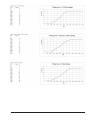
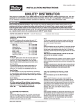
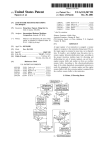
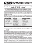
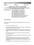
Promaster Distributor Instruction Manual
Pg: 2-4: Ford Applications: Part #: 8350M, 8352M, 8354M
Pg: 5-8: GM Applications: Part #: 8360M, 8361M
Mallory-Ignition.com
INSTALLATION INSTRUCTIONS
FORM INST8577M 05/12
PROMASTER® SERIES - FORD
PLEASE READ THESE INSTRUCTIONS BEFORE INSTALLING.
You should always disconnect the battery, negative lead first, before working on the ignition system. When
you are done reconnect the battery installing the negative lead first.
Included with the distributor:
1 – Machined Ford V8 Distributor
1 - Rotor
1 - Distributor Cap
1 - Wire Retainer
2 - 1.5” Self Tapping Screws
1 - Advance Kit
HOW TO INSTALL THE DISTRIBUTOR
1. D
isconnect the trigger wire from the coil (-) terminal.
Locate the spark plug wire on the original distributor
cap that that is used to set engine timing. See a
service manual for this location. Mark the distributor
cap and distributor housing at this spark plug wire
position.
1 - Tube of Gear Lubricant
1 - O-Ring
1 - Vacuum Advance Lock-Out Kit
(if equipped with vacuum advance)
indicates that the lower end of the distributor shaft is
not properly aligned with the oil pump drive rod. Do
not attempt to force the distributor into position.
Reinstall the hold-down clamp and thread the bolt
6. just enough to exert a very slight pressure against the
distributor. If the distributor was not firmly seated,
manually rotate the engine until the distributor drops
down into place.
2. Turn the engine crankshaft in the direction of rotation
until the timingmark lines up with the top dead center
(TDC) mark on the timing tab. See a service manual
for these locations.
7. With the distributor properly seated, tighten the
hold-down bolt just enough so that the distributor is
held in place, but can still be rotated with a little effort.
3. Remove the distributor cap from the distributor. Do
not remove the sparkplug wires or coil wire at this
time. Make sure the rotor blade points to the mark
made on the distributor housing (from Step 2). If it
does not, repeat Step 2 until the timing mark lines
up (again) with the TDC markon the timing tab.
NOTE: Once you are finished with Step 3, DO NOT turn the
crankshaft until the new distributor is installed.
8. Remove the plug wires one at a time from the old cap
and install them in the corresponding positions of the
new cap. After all wires have been transferred, verify
that the wire in the terminal post that is aligned with the
rotor leads to number one cylinder. If you are unsure of
cylinder number position or firing order, this information
can be found in the service manual that covers your
particular engine. Put on the distributor cap.
4. Note the direction that the rotor is pointing. If you
are replacing a vacuumadvance distributor, note the
direction the vacuum chamber is pointing. Remove
the distributor hold down clamp and remove the
distributor fromthe engine.
9. Reconnect the wiring lead from the distributor to the
ignition switch. At this time you can begin timing.
5. Lower the new distributor into position. The rotor
should be aimed at the same fixed point as was the
rotor from the old distributor. After the new distributor has been lowered into place, you may find that it
hasn’t seated firmly against the intake manifold. This
1
ADVANCE BUSHINGS
HOW TO SET UP THE VACUUM ADVANCE LOCK
OUT ON THE #8350M, #8352M AND #8354M
There are 3 different advance bushings included in
DISTRIBUTORS
the hardware package. The distributor comes with a 21º
bushing already installed. If a different degree of advance is If you do not want to use the vacuum advance canister
desired, follow the procedures to change the bushings.
of the has supplied a lockout mechanism.
1. Remove the two Allen head screws that hold the
advance canister.
BUSHING SIZE
18O
21O
25O
28O
HOW TO SET UP THE ADVANCE BUSHINGS
2. Remove the snap ring that holds the magnetic pickup
assembly in place.
3. Gently lift up on the magnetic pickup plate and slide the
vacuum canister out.
• Take off the locknut and washer at the bottom of the 4. Install the Lockout Plate in place of the canister. Install
the two retaining screws.
advance assembly at the bottom of the bushing pin.
• The bushing will slide off.
5. Install the supplied screw and washer through the Lockout
• Select the new bushing and install.
and tighten.
• Install the washer and locknut.
6. It is important to make sure the pickup plate is parallel
with the housing of the distributor. If it is cocked or
slanted, the paddles of the reluctor may contact the
HOW TO SET UP THE MECHANICAL ADVANCE
pickup. Check the clearance by rotating the distributor
LOCK OUT
shaft. If necessary, use the supplied shims under the
lockout hold-down to correctly position the pickup plate.
1. Remove the springs, weights and the advance stop
bushing from the advance assembly.
NOTE: IF NO SHIMS WERE REQUIRED, USE ONE BENEATH THE
2. Remove the roll-pin and gear at the bottom of the WASHER OF THE LOCK-OUT HOLD DOWN SCREW.
distributor. Remove the roll-pin and stop collar at
NOTE: DO NOT FORGET TO PLUG THE ORIGINAL VACUUM ADVANCE
bottom of distributor housing.
HOSE.
3. Lift the shaft at least two inches out of the housing, but do
not remove the shaft.
HOW TO WIRE THE READY-TO-RUN #8350M,
4. Turn the shaft 180º so the bushing pin slides into the #8352M AND #8354M DISTRIBUTOR
small hole on the advance plate.
Red lead to coil (+) positive
5. Put the locknut and washer back onto the advance Orange lead to coil (-) negative
bushing pin, which locks the advance in place.
Black lead with the larger ring terminal to engine ground.
6. Install stop collar and roll-pin. Install the drive gear and
roll-pin.
NOTE: The #8352M and #8579M distributors for the 221-302
engines are supplied with an iron drive gear for use with
a flat tappet camshaft only. If you are using either of these
NOTE: WHEN INSTALLING A HIGH PERFORMANCE IGNITION distributors in a late model 5.0L engine equipped with a
SYSTEM WITH THIS DISTRIBUTOR, PLEASE REFER TO THE hydraulic roller camshaft or an earlier engine retrofitted
INSTRUCTIONS THAT COME WITH THE IGNITION CONTROL with a hydraulic roller camshaft you will need to change to
BOX. THIS DISTRIBUTOR HAS THE CORRECT COLOR CODE.
a steel alloy drive gear #29418PD. If you are using either
of these distributors in an engine equipped with a billet
mechanical roller camshaft you will need to change to a
bronze alloy drive gear #29429PD.
2
3
INSTALLATION INSTRUCTIONS
FORM INST85551M 05/12
PROMASTER® SERIES - GM
PLEASE READ THESE INSTRUCTIONS BEFORE INSTALLING.
You should always disconnect the battery, negative lead first, before working on the ignition system. When
you are done reconnect the battery installing the negative lead first.
Included with the distributor:
1 – Machined Chevy V8 Distributor
1 - Rotor
1 - Distributor Cap
1 - Wire Retainer
2 - 1.5” Self Tapping Screws
1 - Advance Kit
1 - Gasket
1 - Tube of Gear Lubricant
2 - O-Rings
1 - Vacuum Advance Lock-Out Kit (if equipped with
vacuum advance)
HOW TO INSTALL THE DISTRIBUTOR
6. Install the gasket using plenty of the supplied lubricant.
1. D
isconnect the trigger wire from the coil (-) terminal.
Locate the spark plug wire on the original distributor
cap that that is used to set engine timing. See a
service manual for this location. Mark the distributor
cap and distributor housing at this spark plug wire
position.
7. Reinstall the hold-down clamp and thread the bolt
just enough to exert a very slight pressure against the
distributor. If the distributor was not firmly seated,
manually rotate the engine until the distributor drops
down into place.
2. Turn the engine crankshaft in the direction of rotation
until the timingmark lines up with the top dead center
(TDC) mark on the timing tab. See a service manual
for these locations.
3. Remove the distributor cap from the distributor. Do
not remove the sparkplug wires or coil wire at this
time. Make sure the rotor blade points to the mark
made on the distributor housing (from Step 2). If it
does not, repeat Step 2 until the timing mark lines
up (again) with the TDC markon the timing tab.
NOTE: Once you are finished with Step 3, DO NOT turn the
crankshaft until the new distributor is installed.
4. Note the direction that the rotor is pointing. If you
are replacing a vacuumadvance distributor, note the
direction the vacuum chamber is pointing. Remove
the distributor hold down clamp and remove the
distributor fromthe engine.
5. Lower the new distributor into position. The rotor
should be aimed at the same fixed point as was the
rotor from the old distributor. After the new distributor
has been lowered into place, you may find that it
hasn’t seated firmly against the intake manifold. This
indicates that the lower end of the distributor shaft is
not properly aligned with the oil pump drive rod. Do
not attempt to force the distributor into position.
5
8. With the distributor properly seated, tighten the
hold-down bolt just enough so that the distributor
is held in place, but can still be rotated with a little
effort.
9. Remove the plug wires one at a time from the old
cap and install them in the corresponding positions
of the new cap. After all wires have been transferred,
verify that the wire in the terminal post that is aligned
with the rotor leads to number one cylinder. If you are
unsure of cylinder number position or firing order, this
information can be found in the service manual that
covers your particular engine. Put on the distributor
cap.
10. Reconnect the wiring lead from the distributor to the
ignition switch. At this time you can begin timing.
4
HOW TO SET UP THE VACUUM ADVANCE
LOCK OUT ON THE #8360M AND #8361M
DISTRIBUTORS
If you do not want to use the vacuum advance canister of
the has supplied a lockout mechanism.
1. Remove the two Allen head screws that hold the advance
canister.
BUSHING SIZE
18O
21O
25O
28O
2. Remove the snap ring that holds the magnetic pickup
assembly in place.
3. Gently lift up on the magnetic pickup plate and slide the
vacuum canister out.
Take off the locknut and washer at the bottom of the
advance assembly at the bottom of the bushing pin.
• The bushing will slide off.
• Select the new bushing and install.
• Install the washer and locknut.
4. Install the Lockout Plate in place of the canister. Install the
two retaining screws.
5. Install the supplied screw and washer through the
Lockout and tighten.
1. R
emove the springs, weights and the advance stop
bushing from the advance assembly.
6. It is important to make sure the pickup plate is parallel
with the housing of the distributor. If it is cocked or
slanted, the paddles of the reluctor may contact the
pickup. Check the clearance by rotating the distributor
shaft. If necessary, use the supplied shims under the
Lockout hold-down to correctly position the pickup
plate.
2. Remove the roll-pin and gear at the bottom of the
distributor.
NOTE: IF NO SHIMS WERE REQUIRED, USE ONE BENEATH THE
WASHER OF THE LOCK-OUT HOLD DOWN SCREW.
HOW TO SET UP THE MECHANICAL
ADVANCE LOCK OUT
3. Lift the shaft at least two inches out of the housing, but NOTE: DO NOT FORGET TO PLUG THE ORIGINAL VACUUM
ADVANCE HOSE.
do not remove the shaft.
4. Turn the shaft 180º so the bushing pin slides into the
small hole on the advance plate.
HOW TO WIRE THE READY-TO-RUN #8360M
DISTRIBUTOR
5. Put the locknut and washer back onto the advance
ushing pin, which locks the advance in place.
Red lead to coil (+) positive
6. Install the drive gear and roll-pin.
Black lead with the larger ring terminal to engine ground.
Orange lead to coil (-) negative
NOTE: WHEN INSTALLING A HIGH PERFORMANCE IGNITION
SYSTEM WITH THIS DISTRIBUTOR, PLEASE REFER TO THE
INSTRUCTIONS THAT COME WITH THE IGNITION CONTROL
BOX. THIS DISTRIBUTOR HAS THE CORRECT COLOR CODE.
6
7
family of brands
8
MALLORY IS A TRADEMARK OF PRESTOLITE PERFORMANCE
10601 MEMPHIS AVE. #12, CLEVELAND, OH 44144
216.688.8300 FAX 216.688.8306