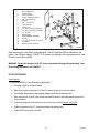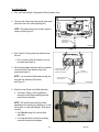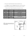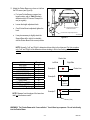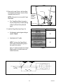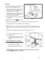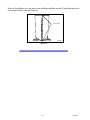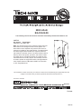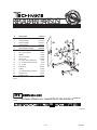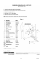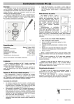
1
Classificatio n:
Referen ce:
Date:
TE02-025c
ITB02-059c
July 28, 2009
ESSENTIAL TOOL: J-45718 ICC TARGET BOARD
This bulletin amendment contains additional Applied Vehicles, information for modifying the Target Board, and a
revised tool. Please discard all previous versions of this bulletin.
APPLIED VEHICLES:
2002 - 2003 QX4 (JR50) - with optional ICC
2003 - 2004 M45 (Y34) - with optional ICC
2006 - 2009 M35/45 (Y50) - with optional ICC
2002 - 2006 Q45 (F50) - with optional ICC
2003 - 2008 FX35/45 (S50) - with optional ICC
2009 FX35/50 (S51) – with optional ICC
2004 - 2009 QX56 (JA60) - with optional ICC
2007 - 2009 G35/G37 Sedan (V36) – with optional ICC
2008 - 2009 G37 Coupe (CV36) – with optional ICC
2008 - 2009 EX35 (J50) – with optional ICC
SERVICE INFORMATION
When performing “Laser Beam Aiming Adjustment” for the Intelligent Cruise Control (ICC) system, a special
tool must be used:
•
This special tool is the “Target Board,” J-45718.
•
This special tool is considered "Essential" and has been sent to each dealer. Your Non-Vehicle account
was charged $600.00 plus applicable taxes and freight.
•
A revised (new) Offset Laser Block Adapter (J-45718-10; replaces J-45718-5) was sent on July 27,
2009 to your dealership. Your Non-Vehicle account will be charged $27.43 plus applicable taxes and
freight.
•
Additional tools and / or replacement parts can be ordered from TECH-MATE at 1-800-662-2001.
Prices are subject to change.
•
The Tool Flyer and Parts Replacement List that were shipped with the tool are included in this bulletin
on pages 11 and 12.
•
The Target Board illustrations in the ACS (Auto Cruise Control System) and CCS (Cruise Control
System) sections of the Electronic Service Manual (ESM), as it applies, do not show several
improvements that were applied to the tool during development. These improvements allow for easier
and faster set up.
•
The Target Board material has special "reflective" properties. Other materials should not be used.
1/16
1.
2.
3.
4.
5.
6.
7.
8.
9.
10.
11.
12.
13.
14.
15.
16.
17.
18.
19.
Support Base
Slider Assembly
Target Board
Vertical Support
Height Adjustment Knob
3/8 - 16 Cap Screw
Washer
3/8 - 16 Hex Nut
Laser Pointer
Plastic Clip
10 - 24x.5 Socket HD Screw
10 - 24x.63 Socket HD Screw
10 - 24 Nut
Bead Chain
Off-set
Mounting
Plate
Block Adapter
(revised)
O-Ring
10 - 24x.35 Socket HD Screw
T-Handle
Bullseye Level Indicator
19
3
12
13
9
4
18
11
16
15
5
2
10
14
17
8
7
6
1
TP020500
Figure 1
When performing the "Laser Beam Aiming Adjustment," use the Target Board Set-Up Instructions in this
bulletin. Also, follow the steps for CONSULT II / III operation (as applicable) in the appropriate section of the
Electronic Service Manual (ESM).
WARNING: Do Not look straight into the ICC sensor (laser beam discharge) when performing “Laser
Beam Aiming Adjustment” with CONSULT.
SET-UP PROCEDURES
Vehicle Set-Up:
1. Prepare the vehicle for “Laser Beam Aiming Adjustment:”
•
Place the vehicle on a flat level surface.
•
Make sure you leave a minimum of 18 feet (5.5 meters) of space in front of the vehicle.
•
Check/adjust tire pressure to the specified pressure for the vehicle being serviced.
•
Make sure there is “no-load” in the vehicle other than the driver (or equivalent weight placed in the
driver's position).
•
Coolant and engine oil must be filled up to the correct level, and the fuel tank must be full.
•
Shift the gear selector into “P” position and release the parking brake.
•
Clean the ICC sensor with a soft cloth.
2/16
ITB02-059c
Target Board Set-Up:
2. First, you'll need a length of string about 30 feet (9 meters) long.
3. Tape one end of the string to the ground at the center
point of the rear of the vehicle (see Figure 2).
NOTE: The Infiniti emblem can be used to align the
center point (see Figure 2).
center
point
Tape string
to ground at
center point.
TP020466
Figure 2
4. Now, "extend" the string under the vehicle and out
the front.
• Pull it out about 18 feet (5.5 meters) in front of
the vehicle (see Figure 3).
5. Pull the string straight and align it with the centerline
of the vehicle front, then tape the string to the
ground (see Figure 3).
NOTE: You can use the Infiniti emblem to align the
string with the centerline of the vehicle
(see Figure 3).
Use Infiniti emblem
to align string with
centerline of vehicle.
18 Feet
(5.5 meters)
Tape end of string
to the ground.
TP020467
Figure 3
6. Attach the Laser Pointer to the Slider Assembly.
•
As shown in Figure 4, the Target Board is
removed from the Slider Assembly when the
Laser Pointer is attached.
Slider Assembly
Level Indicator
Laser Pointer
NOTE: The Laser Pointer mounting is off-set,
depending on the vehicle you're working on. It could
be up, down, or to the side (left/right). See Figures
4 and 4a.
• See Table A on page 4 for vehicle off-set
application.
• To change the off-set, remove the mounting
screw and rotate the block adapter.
3/16
Revised (New) Offset Block Adapter
Figure 4
ITB02-059c
Vehicle
QX4 (JR50)
QX56 (JA60
Q45 (F50)
M45 (Y34)
M35/45 (Y50)
EX35 (J50)
G35/G37 Sedan (V36)
G37 Coupe (CV36)
FX35/45 (S50)
FX35/50 (S51)
Table A
Position
17 mm
17 mm
17 mm
17 mm
28 mm
28 mm
42 mm
42 mm
0 mm *
14 mm
Use this Hex
Screw for:
All Hex Screws
have mm setting
values.
42 mm setting
28 mm setting
14 mm setting
17 mm setting
0 mm (off-set)
setting *
Figure 4a
* The block adapter is mounted horizontally
with the hex screw shown in Figure 4.
400 390 380 370 360 350 340
15
14
330 320
13
290
310 300
280
270
250
260
240
210
190 180
170 160
7
6
10 inch mark
400 390
380
15
370
360
14
350
340
330
13
320
310
300
12
290
280
11
270
260
250
10
240
230
220
210
9
Target Board
Support Base
NOTE: The support base has an alignment
scale on both sides, driver and passenger.
Figure 5 shows the driver side.
200
8
9
7. Now, you'll need to align the Target Board Support
Base to the vehicle as follows:
a. Look at the chart on page 5 to determine
where the string should be aligned.
220
230
10
11
12
200
8
190
180
7
170
160
6
Align string with
scale in correct location.
As shown, string is
aligned at 10 inches
(254 mm) for QX4.
Front of vehicle
String
TP020469
Figure 5
4/16
ITB02-059c
b. Set the legs of the Target Board Support Base into alignment (parallel) with the string.
c. Look at Table B below, and make note of Alignment (measurement) for the vehicle you're working on.
d. Move the base left or right and align the string to the correct reading on the scale, or to the center.
• Make sure the legs of the Target Board Support Base are always parallel to the string.
Vehicle
QX4 (JR50)
2002-2004 Q45 (F50)
2005-2006 Q45 (F50)
M45 (Y34)
2006-2007 M (Y50)
2008-2009 M (Y50)
FX35/FX45 (S50)
FX35/50 (S51)
QX56 (JA60)
G35/G37 Sedan (V36)
G37 Coupe (CV36)
EX35 (J50)
Use Scale Side
Driver
Driver
N/A
Driver
Passenger
Passenger
Driver
Passenger
Driver
Passenger
Passenger
Passenger
Alignment
10 inches (254 mm) as shown in Figure 5
10.8 inches (275 mm)
Center (see Figure A, below)
12.8 inches (324 mm)
10.5 inches (266 mm)
9.88 inches (251 mm)
12.2 inches (310 mm)
12.4 inches (315 mm)
8.6 inches (218 mm)
15.91 inches (404 mm)
9.72 inches (247 mm) for “Sport” series bumper
10.12 inches (257 mm)
Table B
Center support of
Targer Board Base
Driver side of
Target Board
Base
NOTE: For vehicles requiring string alignment at the
center (as indicated in the chart above), align string
as shown in Figure A.
400
390
380
15
370
360
14
350
340
330
13
320
310
300
12
290
280
11
270
260
250
10
240
230
220
210
9
200
8
190
170
180
7
160
6
Front of vehicle
String aligned
at center of
Target Board
Base
TP020469c
Figure A
5/16
ITB02-059c
8. Now you'll set the distance from the front of
the Laser Pointer to the front most edge of the
vehicle front bumper.
Use Table C below to determine the
distance to be measured.
Measure
Measure from
from the
the
front
to
front bumper
of the ICC
the
fronttoofthe
the
sensor
Laser
Pointer.
front of
the Laser
Pointer.
Use
chart5 to
16 feet
inches
determine
(5 meters)your
vehicle’s
distance.
Distance
Vehicle
Q45 (F50)
M45 (Y34)
16.4 feet (5 m)
FX35/45 (S50)
QX56 (JA60)
QX4 (JR50)
M35/50 (Y51)
FX35/45 (S50)
G35/G37 Sedan (V36) 12.8 feet (3.9 m)
G37 Coupe (CV36)
EX35 (J50)
Table C
T-Handle
Storage
Laser Pointer
20
TP020470
10
20
30
Figure 6
Turn level adjustment knobs until the
bubble in the level indicator is centered.
30
20
10
10
NOTE: While moving the Support Base to this
distance, make sure the string stays correctly
aligned.
20
USE
ADJUSTING
FEET TO
LEVEL
30
•
Put the height of the Laser Pointer about
equal to that of the ICC Sensor’s before
measuring.
30
•
J-45718
KENT-MOORE
USA
Level
indicator
TIP: There is a T-handle used for Target Board
mounting. Store the T-handle in the opening at
the top of the Vertical Support when not in use
(see Figure 6).
Center
adjustment
400 390 380 370 360 350 340
330 320 310 300 290 280 270
260 250 240 230 220 210 200
190 180 170 160
15
14
13
12
11
10
9
8
7
400 390 380 370 360
350 340 330 320 310
300 290 280 270 260
250 240 230 220 210 200
190 180 170 160
15
14
13
12
11
10
9
8
7
6
6
TP020471
Figure 7
9. Now you'll need to “level” the Target Board
Support Base (see Figure 7).
•
Bring the bubble into the center of the level
indicator. To do this, turn the knobs on the
Support Base legs.
NOTE: If the work surface under the support
base is slightly uneven, use the center
adjustment for additional leveling.
10. Turn the Laser Pointer ON. The switch is at its
base (see Figure 8).
Laser Pointer
ON/OFF Switch
Figure 8
6/16
ITB02-059c
11. Adjust the Pointer Beam up or down so it strikes
the ICC sensor (see Figure 9).
• For Laser Pointer Beam-on-sensor lens
target location, refer to Table D below to
determine which ICC sensor “Example” to
use (as a guide).
•
Loosen the height adjustment knob.
•
Once Pointer Beam is adjusted, tighten the
knob.
Adjust pointer beam to
strike ICC sensor.
Pointer beam height adjustment
•
TP020472b
It may be necessary to slightly rotate the
Support Base left or right to horizontally
aim the Pointer Beam in the correct position.
Figure 9
NOTE: Normally, “Left” and “Right” is determined when sitting in the driver seat. For this procedure
only, “Left” and “Right” will be determined when standing in front of and looking at the front of the
vehicle.
Center Line
Vehicle
QX4 (JR50)
Q45 (F50)
M45 (Y34)
2006-2007 M (Y50)
2008-2009 M (Y50)
2003-2008 FX35/45 (S50)
2009 FX35/50 (S51)
QX56 (JA60)
G35/G37 Sedan (V36)
G37 Coupe (CV36)
EX35 (J50)
Table D
Left Side
Example
A
A
A
B
C
A
C
A
C
C
C
Right Side
Example A
Center Line
22 mm (0.87 in.)
Example B
92 mm
(3.62 in.)
22 mm (0.87 in.)
NOTE: Measure from the edges of the laser lens
itself, not the fascia around it.
Example C
38 mm (1.5 in)
WARNING: The Pointer Beam emits “laser radiation.” Avoid direct eye exposure. Do not look directly
into the Pointer Beam.
7/16
ITB02-059c
12. Remove the Laser Pointer―with the off-set
block adapter still attached―from the Slider
Assembly (see Figure 10).
Hand-tighten the T-handle.
Vehicle
Q45 (F50)
M45 (Y34)
2003-2008 FX35/45 (S50)
QX56 (JA60)
QX4 (JR50)
2006-2007 M (Y50)
2008-2009 M (Y50)
2009 FX35/50 (S51)
G35/G37 Sedan (V36)
G37 Coupe (CV36)
EX35 (J50)
Figure 11 shows an example for a Target
Board located on the driver side of the
Vehicle Center line.
Target Board
Face
TP020473
Figure 10
NOTE: The face of the Target Board,
when angled, should be facing toward
the center of the vehicle.
xx
30
•
20
Set alignment mark at degree setting as
stated in Table E.
E G
US STINTO
JU
L
AD FEET VE
LE
Laser Pointer
13. Install the Target Board (see Figure 10):
•
18
57 RE
-4 OO A
M
T- US
10
If the Target Board Base is bumped or
moved, its alignment procedure (starting
at Step 7) will need to be performed
again.
30 20
Align
Alignmark
markon
on
Target
TargetBoard
Board
mount
mountwith
with 20
degree mark
specified
on stand.
degree
mark
on stand.
NOTE: At this point, do not move the Target
Board Base.
•
Target
Board
T-Handle
Degrees Setting
20°
25°
Table E
Vehicle Center
Line
xxx
xxxx
xxx
xxx
Figure 11
8/16
ITB02-059c
IMPORTANT:
Follow the procedure below if your Target Board’s height
is not already at the Final Height measurement.
TOP
Target
Board
• Due to the lower position of the ICC sensor on the
2006 M and 2005 Q45, the Target Board will need
to be modified for use on these vehicles.
• This modification is also recommended when using
this tool on 2003-2004 M45. It will make it easier to
install the board in the correct position.
• This modification will not affect the use of the board
on other vehicles.
Final Height
(after cut)
630 mm (24.8 in)
Cut 70 mm (2.75 in)
off of the bottom.
TP050093
Figure 12
• Cut 70 mm (2.75 in) off of the bottom of the Target
Board.
• Score the white reflective tape with a razor knife, and then use a suitable handsaw to make the cut.
• The final height (after cut) of the board should be 630 mm (24.8 inches).
NOTE: Target boards, or complete tools purchased after March 23, 2004, will already be the smaller size
and won’t need to be cut. If you’re not sure, measure your board. The new size is 630 mm (24.8 inches)
high.
• The MSDS for the Target board is attached at the end of this TSB (pages 11 and 12).
14. Set up the Background Board behind the Target
Board (see Figure 13).
•
The Background Board prevents reflection from
objects such as workbenches, walls or other
vehicles.
Vehicle and Target Board set-up is complete.
15. Perform "Laser Beam Aiming Adjustment" Procedure.
•
Use CONSULT II / III, as applicable.
•
Refer to the appropriate section of the ESM.
Background
Board
At le
ast
1
5"
At leas
t 15"
Background
Board must
extend at least
15 inches beyond
the Target Board
on each side.
String
Target
Board
TP020474
Figure 13
WARNING: Do Not look straight into the ICC sensor (laser beam discharge) when performing
“Laser Beam Aiming Adjustment” with CONSULT.
9/16
ITB02-059c
When the Target Board is not in use (stored), wrap the Background Board around the Target Board and use the
Velcro straps to hold it in place (see Figure 14).
Velcro straps
TP020475
Figure 14
10/16
ITB02-059c
2002 Infiniti
EG-332-02-09
The following service tool has been classified essential by Nissan North America, Inc
J-45718
ICC System Target Board
Application: Q45, QX4, M45
Note: This special service tool is required to adjust (aim) the
laser beam on the Intelligent Cruise Control System. The
laser beam must be adjusted every time the ICC sensor is
removed or installed on the noted vehicles. The special black
and white target board materials have a specific reflective
rate needed for the laser sensor. The stand includes a built-in
bulls-eye level, laser pointer, protractor, and scale for faster
and easier set-up. A flat black backdrop is included to eliminate reflections from nearby objects. The backdrop can also
be used to protect the target board while in storage between
uses. Please reference ITB02-059 in ASIST for information
on ICC Target Board use.
This essential tool will be invoiced to your Infiniti non-vehicle account at $600.00 (plus appropriate taxes and
freight) in accordance with your dealer agreement with Nissan North America, Inc.
Promotion # IF02-532A
586-578-7375
586
TP020481
11/16
ITB02-059c
REPLACEMENT PARTS LIST
#
Description
Order #
1
Support Base
J-45718-1
2
Slider Assembly
J-45718-2
3
Board Assembly
J-45718-3
4
Vertical Support
J-45718-4
9
Laser
J-45718-5
J
•45718•10
Block Adapter (revised)
15
J-45718-5
5
Clamp Knob
511910
6
3/8 - 16 Cap Screw
10057
7
Washer
10258
8
3/8 - 16 Hex Nut
10204
10
Plastic Clip
513202
11
10 - 24x.5 Socket HD Screw
11434
12
10 - 24x.63 Socket HD Screw
11152
13
10 - 24 Nut
10197
14
Bead Chain
513201
16
O-Ring
10265
17
10 - 24x.38 Socket HD Screw
14276
18
Clamp Knob
511916
19
Bullseye Level
511979
Not
Background Board
J-45718-6
Shown
19
18
3
4
16
12
13
15
11
5
2
9
10
17
14
8
7
6
1
586-578-7375
513817
586
TP020482
12/16
ITB02-059c
13/16
ITB02-059c
14/16
ITB02-059c
15/16
ITB02-059c
(revised)
16/16
ITB02-059c