1
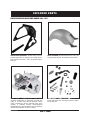
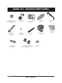
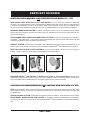
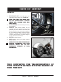
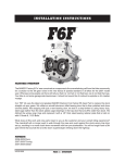
v5-060208 B AKER 300 ™ Install ation i nstr uct i ons table of contents: 2. Overview 3. BAKER 300TM Wide Tire Kit Included Parts 4. BAKER 300TM Wide Tire Kit Included Parts Detail 5. BAKER 300TM Wide Tire Kit Included Parts Detail (Continued) 6 Parts Not Included (But Required for Kit) 7. Skills, Knowledge & Tools 8. Checklist 9. Stock Motorcycle Disassembly 10. Stock Motorcycle Disassembly (Continued) 11. BAKER 300TM Assembly | Transmission 12. BAKER 300TM Assembly | Transmission (Continued) 13. BAKER 300TM Assembly | Swingarm 14. BAKER 300TM Assembly | Primary 15. BAKER 300TM Assembly | Primary (Continued) 16. BAKER 300TM Assembly | Frame Components 17. BAKER 300TM Assembly | Rear Wheel 18. BAKER 300TM Assembly | Pulley Cover 19. BAKER 300TM Assembly | Rear Wheel 20. BAKER 300TM Assembly | Rear Fender 21. BAKER 300TM Assembly | Finish Line 22. Directory of BAKER 300TM Compatible Products 23. Terms 24. Disclaimer V.5-060208 TABLE OF CONTENTS over v iew tm The BAKER 300™ Wide Tire Kit, for Evo , is designed for use with all stock 19911999 Harley-Davidson® SoftailTM models. The BAKER 300™ kit when installed with the additional parts as listed effectively converts a Softail from a 5-speed, left side drive, stock rear tire motorcycle into a 6-speed, right side drive, fat tire custom. TM FEATURES 6-speed transmission with DD6 RSD technology The BAKER RSD DD6 transmission provides smoother shifting, positive neutralfinding, and reduced cruising RPM on the highway as compared to the stock 5-speed. With proven technology and helical 4th, 5th, and 6th gears, town and highway cruising is noise-free. No disassembly of the stock 5-speed is required. Right Side Drive Right side drive is the critical variable in the equation of balancing a fat tire custom motorcycle. Left side drive fat tire motorcycles rely on offsetting (moving over) the engine, transmission, and/or the primary drive which moves the powertrain centerof-mass to the left and creates an inherent balance bias to the left. Left turn and right turn body English is noticeably different with left side drive; not so with right side drive. 300 Series Tire The street look of a fat rear tire is the essential element of a custom American motorcycle. The 300mm tire with it’s 12-inch wide stance has porn star caliber curbside appeal with an aspect ratio that screams speed. PAGE | OVERVIEW V.5-060208 i nclud ed part s Parts Provided with the BAKER 300™ Kit Swingarm Assembly: Durable black and clear Rear Fender: Media blasted finished, heavy-duty DD6 All necessary hardware: Note: Only one of each part shown here. See Page 4 and 5 for quantities of each part. powdercoated finish on swingarm and splash guard, heat treated 4140 steel 1” axle, and spherical pivot bearings. RSD Transmission Assembly: Polished, wrinkle black or silver finish complete with pulley, or 24 tooth chain sprocket optional, chrome pulley cover/shroud, chrome cable ball ramp clutch actuator, or Hydraulic Actuator. Newly-designed BAKER billet top cover with hidden vent. No assembly required. Speedometer recal box included. V.5-060208 13 gauge steel with 3/8” thick hidden internal struts. PAGE | PARTS baker 300 ™ i ncluded part s Detail 3/4” - 16 x 5” Swingarm Pivot Bolt Part # 15373 (Qty. 1) Dog Leg Spacer Part # WT865 (Qty. 1) 1” Axle Collar Part # 99936 (Qty. 2) WTK Fender Part # WT880 (Qty. 1) 3/8” - 24 x 1/4” Axle Adjustment Set Screw Part # 37C25KKCS (Qty. 2) 3/8” - 24 x 1-1/4” Axle Adjustment Screw Part # 37125KKCS (Qty. 2) 1/2” - 20 x 1-1/2” Fender-To-Frame Bolt Part # 50150KBCPR (Qty. 2) 5/16-18-Nylock Part # 37021 (Qty. 4) 3/8” - 16 x 1-1/2” Fender-To-Frame Bolt Part # 37C150KBCPR (Qty. 4) 1/2” AN-Washer Fender-To-Frame Part # 9900272 (Qty. 2) Pivot Bolt Cover (Left and Right Side) Part # WT869C (Qty. 2) 5/8-18 x 1” Grade 8 Axle Retaining Bolt Part # 99618 (Qty. 2) 10-32 x 1/2” Right Pivot Cap Set Screw Part # 73248R (Qty. 2) 5/16-18 x 3/4” Part # 31C75KBCS (Qty. 4) 3/8” - AN Washer Fender Washer Part # AN960C616 (Qty. 6) 5/16” AN Washer Part # 6100 (Qty. 4) Right Side Wheel Spacer (w/ chain applications only) Part # WT893P (Qty. 1) Right-Side Brake Bracket to Axle Spacer Part # WT905 (.320” - PM Wheels) Part # WT907 (.218” - Xtreme Wheels) (Qty. 1 ea.) PAGE | BAKER 300™ 3/8” - 16 x 3” Dog Leg Bolt Part # 37C300KSSPR (Qty. 2) Right Side Wheel Spacer (w/ belt applications only) Part # WT893P (Qty. 1) Speedometer Recalibration Box Part # 95E-56 (Qty. 1) Swingarm and Splashguard Assembly Part #’s:WT881B/WT882B (Qty. 1) Comp Sprocket Part # 158-56 (Qty. 1) Chain Tensioner Assembly (Qty. 1) 1/4” - 20 x 1” Ignition Module Socket Head Cap Screw Part # 25C100KCSS/P (Qty. 2) V.5-060208 baker 300 ™ i ncluded part s d etail Brake Braket Spacer Part # WT906P (.590” for PM Wheels) Part # WT908P (.430” for XM Wheels) (Qty. 2) Seat Nut w/ Clip Part # 59768-97 (H-D) (Qty. 1) Transmission RSD BAKER Direct Drive 6-Speed Part # R701-DD6 (Qty. 1) 1/4” - 20 x 1-1/4” Zinc-Plated ECM Socket Head Cap Screw Part # 93207 (Qty. 4) 10 - 32 x 3/8” Axle Cover Bolt Part # 10F37KBCPR (Qty. 4) 1” Axle Part # WT859 (Qty. 1) 5/16” - 18 X 1½” Brake Bracket Bolt Part # 31C150KCSPR (Qty. 2) V.5-060208 Left Side Wheel Spacer (1.950”) Xtreme Machine: Part # WT894AP ( 1.389”) Performance Machine: Part # WT904AP (Qty. 1 each) Axle Cover Part # WT854C (Qty. 2) 84-Pitch Primary Chain Part # 4282-84-56 (Qty. 1) Pivot Tube Spacer Part # 99413 (Qty. 2) PAGE | BAKER 300™ Dog Leg Part # WT857B (Qty. 1) WTK Pulley Cover Part # WT858 (Qty. 1) part s No t i ncluded ADDITIONAL PARTS REQUIRED (NOT Provided with the BAKER 300™ Kit) Rear Wheel with 300mm tire, pulley, and rotor: Any 10.5” wheel from Performance Machine™ Forge-Tec™ or Extreme Machine™ is fully compatible with the BAKER 300™ Wide Tire Kit. See the Contacts Directory in the back of the installation manual for contact listings. Other wheel companies’ products may be compatible, but at the time of this writing BAKER Drivetrain Engineering has only validated fitment of the aforementioned companies. Driveside Rear Brake System: The stock rear caliper and brake rotor is not compatible with the BAKER 300. A Performance Machine™ driveside rear brake system (p/n 1284-00074A-1-CH) can be purchased directly from Performance Machine™. Two Braided Steel Brake Lines and BanJo Fittings: RussellTM 28” and RussellTM 16” brake lines. Good RidgeTM rear brake switch “T” and 10mm #3 male 35º Banjo fitting (See page 8 for Rear Caliper Brake Checklist and page 24 for BAKERTM 300 Compatible Product Directory). Exhaust System: Right side drive compatible to date, BAKER Engineering has tested and validated fitment of exhaust systems from several manufacturers. See the Directory of BAKER 300TM Compatible Products on page 22. Rear Taillight/License Plate Assembly: We recommend taillights that will mount to the swingarm, footpeg, or derby cover like the ones shown below available from Drag Specialties™. Example footpeg-mounted style Example swingarm mounted style Example derby cover style Heritage SoftailTM and Fat Boy™ SeatS (or any seats w/ side-mounted tabs): Because these models utilize additional seat mounts on the side of the frame, the factory seats on the Heritage SoftailTM and Fat Boy™ are not compatible with the BAKER 300™ kit. See optional parts for factory seats that will work. OPTIONAL PARTS (RECOMMENDATIONS NOT Provided with the BAKER 300™ Kit) Seat: Harley-Davidson® offers a number of custom-styled contemporary seats like the ones shown in the H-D® Parts and Accessories Catalog. The Stripper™, BadlanderTM and Sidekick™ are nicely styled and technically compatible with the BAKER 300™. Legend Air Ride System: An adjustable air suspension system for Softails™ , minor fabrication may be required. Front Wheel, Brake Rotor, and Caliper: To complete and finish off the BAKER 300™ transformation, you may want to select a front wheel rotor and Performance MachineTM caliper assembly to compliment and match the rear. PAGE | PARTS V.5-060208 SKI LL s, K NOWLE DGE & TOO l s REQUIRED READING It is highly recommended that the following H-D® publications are available for your reference as they are referred to in the instructions. � Factory Service Manual for your year and model � Factory Parts Manual for your year and model � Genuine Parts and Accessories Catalog Skill Level As with most things in life, there is no substitute for skill and experience. We highly recommend that only a seasoned experienced technician with an extensive background with Harley-Davidson® motorcycles and the American custom aftermarket successfully complete the BAKER 300™ installation. SPECIALTY TOOLS � PULLEY NUT SOCKET: Many tool boxes don’t have one of these. To make your life a bit easier, we make the mother of all pulley nut sockets, which is made from one piece of bar stock and hard chrome plated for a super tough finish. The throat of our wrench is deeper than other scokets to enable service work on right-side-drive and left-sidedrive 5 & 6 transmissions. BAKER Part # TOOLD-56 � Sawzall or cutoff wheel � 13/16” socket (for clutch nut) � 11/2” socket (for compensating sprocket nut) V.5-060208 PAGE | SKILLS, KNOWLEDGE & TOOLS c h ec klist Prior to disassembly of your stock Softail™ to begin the BAKER 300™ transformation, it is recommended that the following checklist be utilized to make sure you have all the necessary parts to complete the job: BAKER 300™ Wide Tire Kit � Transmission Assembly � Rear Fender Kit � Swingarm and Hardware Kit Additional Parts (Not included with the kit) � 10.5” wide rear wheel � Avon or Metzeler 300 tire � Rear wheel pulley, with bolts (for 1-1/8” Twincam belts) � Rear wheel brake rotor, with bolts � Driveside rear brake system : Performance Machine Caliper and Bracket p/n 1284-00074A-1 � 1-1/8” Twincam Softail drive belt TM TM TM TM Rear caliper brake lines and fitting Available through Drag Specialties™ � Russell SS DOT Brake Line 16” P/N 58362S � Russell SS DOT Brake Line 26” W/CL P/N 58092S � Drag Specialties 10MM BANJO BOLT P/N DS098109 � Drage Specialties 10MM BANJO #3 MALE 35º P/N DS098150 � Good Ridge Rear Brake Switch “T” P/N MCHD014 � Drag Specialties 10MM BANJO #3 MALE 90º P/N DS098151 � Exhaust system � Exhaust seals � Rear taillight/license plate assembly � Transmission and primary oil Spectro Heavy Duty Platinum 6- � DOT 5 brake fluid � Seat (optional) � Front wheel, brake rotor, and caliper (optional) � Hydraulic Options: -3/8”-24 Banjo Bolt Speed Transmission Lubricant-- Spectro p/n R.HDPG6 and Spectro Heavy Duty Primary Chain Case Oil-Spectro p/n R.GAPCL Spectro DOT 5-Spectro p/n GABF -10mm Banjo fitting - 11/16” Bore Clutch Lever Assembly - #3 Brake Line � 530 Chain Final Drive (optional) PAGE | CHECKLIST V.5-060208 st oc k m o t o r cycle di s assembly With a completed BAKER 300™ Softail™ can commence. 1. component checklist, disassembly of the stock Disconnect and remove the battery 2.Drain Fluids: The transmission and primary drive oils need to be completely drained. Refer to the H-D® Factory Service Manual. 3.Elevate the rear wheel off the ground by positioning the motorcycle on a suitable jack or motorcycle lift. The motorcycle will remain in this position until the transformation from Page 9 to Page 20 is complete. So make sure it is safe, stable and there is 5-feet-or-so of peripheral room to move about. 4.Disassemble: Remove the transmission, primary drive housing, clutch components, rear tire, swing arm, exhaust pipes, and rear fender. Refer to the Factory Service Manual. Also, remove the rear brake caliper and brake line all the way up to the rear master cylinder. The primary drive components will be reinstalled as a part of the BAKER 300™ transformation.Figure 1 5. Cutting Fender Supports: The fender Bolt into place the fender support cutting templates (marked L for left and R for right and provided in the kit) to the sides of the frame by using the bolts from the support covers. L and R must face out for correct template orientation. Use a reciprocating saw (aka sawzall) or abrasive cutoff wheel to remove the supports as shown in Figure 2. With a large flat file, break (smooth off) all sharp corners and edges. The resultant bare metal will not be visible once the BAKER 300™ fender is installed. struts must be removed in order for the new BAKER 300TM fender to fit. Figure 1 Cut fender strut along top edge of template CHECK NEWLY CUT FRAME FOR FENDER FITMENT AT THIS POINT BEFORE PROCEEDING. Additional material may need to be removed for proper fitment. As an anti-corrosion measure, paint the exposed bare metal with primer and/or paint. (Disassembly Continued on next page) V.5-060208 PAGE | DISASSEMBLY Figure 2 st oc k m o t o r cycle di s assembly (Disassembly Continued) Tapped Holes 7.Chasing the Threads on Frame: To aid in the assembly process use a tap and tap cutting fluid to clean out the threads of the fender and dog leg attachment holes in the frame. figure 3. Use tap sizes: Two* 1/2”-20 Six* 3/8”-16 � 1/2”-20 � 3/8”-16 NOTE: The quantity of tapped holes in FIGURE 3 to reflect the total amount on both sides. 8. Final disassembly Checks: With the completion of the disassembly process, the motorcycle should look like Figure 4. Figure 3 Figure 4 PAGE 10 | DISASSEMBLY V.5-060208 B AKER 300 ™ Assembly We highly recommend that the entire BAKER 300™ Wide Tire Kit be installed and “mocked up” to validate fitment and function. After a successful mock up is complete, the BAKER 300™ fender can be removed and painted to match the tank and front fender. Transmission: 1.Pulley Cover: Remove the pulley cover and actuator assembly from the transmission. Set the pulley cover and pulley aside for now. It will be reinstalled towards the end of the assembly process. (.150” Thick) 2. Speed Sensor: Reinstall the stock speed sensor with spacer provided in kit for proper sensor to gear clearance and function. Figure 5 & 6. (STEPS CONTINUED ON NEXT PAGE) Figure 5 Figure 6 V.5-060208 PAGE 11 | BAKER 300™ ASSEMBLY B AKER 300 ™ Assembly Transmission (CONTINUED): 3.Transmission Installation: Before installing transmission in the motorcycle place a piece of masking tape over both ends of the mainshaft so that the clutch actuator rod does not fall out and become damaged. Install transmission through the left side of motorcycle. Figure 8a. Gently maneuver transmission into position Figure 7 PAGE 12 | BAKER 300™ ASSEMBLY V.5-060208 B AKER 300 ™ Assembly SWING ARM: 1.Splash Guard: Remove the splash guard from the BAKER 300™ swing arm and set aside with the provided hardware for later installation. 2.Install Dogleg: Install BAKER 300™ Dogleg using parts supplied in the kit: (1) Pivot Bolt Hex Head 3/4” - 16” x 5” QTY: 1 (2) Chrome SHCS Bolts 3/8” - 16x3” QTY: 2 Also use fender bolts for alignment of dogleg (1) 1/2” - 20 x 11/2” (2) 3/8” - 16 x 11/2” 3. FIRST INSTALL 11/8” REAR DRIVE BELT AROUND THE TRANSMISSION: Install dogleg onto right side of frame. Slide pivot bolt supplied in kit with red thread lock and stock lock washer, through the BAKER 300™ dogleg. Install two 3/8”-16x3” bolts with blue thread lock. Install fender bolts loosley (just for alignment purposes). Make sure belt is in between dogleg. Figure 8. Figure 8 4.Install swingarm: Using the provided BAKER Pivot Tube and Swingarm Spacers, install the swingarm. Remember that the swingarm spacers go between the pivot bearings and provided, threaded pivot center tube. Use stock left side pivot bolt and washers with red thread lock. Tighten both pivot bolts per Factory Service Manual. Tighten bottom dogleg bolts to 21-31ft/lbs. Remove fender bolts. Figure 9 V.5-060208 PAGE 13 | BAKER 300™ ASSEMBLY B AKER 300 ™ Assembly PRIMARY: Counter bore side of coupler facing outward 1.Shifter Linkage Arm: Install forward control factory shifter linkage to transmission shifter arm. 2.Inner Primary: Install inner primary per service manual. After installing inner primary, shift transmission by hand through the gears to make sure linkage will not hit the inside of the inner primary. 3. Tranmission: Tighten transmission bolts per Service Manual 4.Starter: Bolt to inner primary per Factory Service Manual. FIGURE 10. 5.DD6™ Chain Tensioner Anchor Plate: Install chain tensioner assembly (provided in kit) figure 11 (removal of anchor plate is Figure 10 necessary to install new tensioner nut. Use red thread lock and torque anchor plate to 12-14 ft-lb. or 16.3-19.0 nm.) 6.DD6™ Chain Tensioner Shoe: Install tensioner shoe and bolt in place loosely at this time. 7.Primary Chain & Clutch Basket: Install compensating sprocket, chain, and clutch basket. (compensating sprocket and chain provided in kit.) (Do not use thread lock at this time.) Torque compensating sprocket and clutch basket nut per Factory Service Manual. Tighten chain as tight as you can. (PRIMARY assembly continued on next page) Figure 11 Figure 12 PAGE 14 | BAKER 300™ ASSEMBLY V.5-060208 B AKER 300 ™ Assembly PRIMARY assembly (CONTINUED): 8.Primary Chain Alignment: Perform a sprocket alignment check at this time. Refer to Factory Service Manual. (A different thickness washer may be required for proper alignment of primary chain. Which can be purchased at your local Harley Davidson® dealer) Once verification of correct alignment has been verified loosen primary chain, remove compensating sprocket nut and clutch basket nut. Apply (red) thread lock to compensating sprocket nut and clutch basket nut and torque to factory specifications. 9.Chain Adjustment: Remove chain tensioner bolt and apply (red) thread lock, adjust chain per service manual, and torque to 21-29 ft-lbs. figure 13. 10.Outer Primary: Install outer primary per service manual. 11.Oil Tank: Install oil tank and lines per Factory Figure 13 Service Manual Figure 14 V.5-060208 Figure 15 PAGE 15 | BAKER 300™ ASSEMBLY B AKER 300 ™ Assembly FRAME COMPONENTS: 1. Rear Brake Line: Install brake lines, fittings, 2. Speedometer Re-Calibration: 4. SplashGuard: Reinstall splash guard with and brake switch from rear master cylinder to the swing arm. (Running the brake line along the frame as the original was located. Use a 16” flexible brake line from the master cylinder to brake light switch ‘T’. Use a 26” flexible line from brake ‘T’ to rear caliper. Routing the line through the swing arm to later be placed in the ‘notch’ in the provided BAKER 300™ splashguard. Install the provided speedometer re-calibration box between to the speed sensor harness and the speed sensor. (See Re-cal box for instructions and adjustment info.) figure 16 the provided hardware making sure to route the rear brake line through the notch in the bottom right of the splash guard. Torque to 220 in-lbs. PAGE 16 | BAKER 300™ ASSEMBLY Figure 16 V.5-060208 B AKER 300 ™ Assembly PULLEY COVER and fluids: 1.Mechanical Clutch Actuator Cover: Remove outer mechanical actuator cover with gasket from chrome pulley cover. Install stock clutch cable through chrome actuator cover. (Do not over tighten clutch cable to actuator cover) Hook cable end to ball and ramp assembly. Put a liberal amount of grease around the ball and rampa and feral. Make sure you seat ball and ramp properly in actuator cover. Figure 17. 2.Hydraulic Clutch Actuator Cover The Hydrualic Clutch will arrive with the gasket and bolts in place, torqued to 110 in-lbs with blue thread lock. The o-rings around the piston are already lubed and it is ready to be bolted to the transmission bearing door along with the pulley cover. The actuator can be bleed in the manner similar to the brakes and the hydraulic fluid port is designed for use with a 3/8”-24 Banjo Bolt and Dot 5 brake Fluid Spectro P/N-GABF. Figure 17 3.Pulley Cover: Apply (blue) thread lock to pulley cover bolts and then reinstall pulley cover. Torque the bolts to 200 in-lbs. (3pc 5/16-18x1” Bolts). Apply (blue) thread lock to actuator cover bolts and reinstall actuator cover with gasket to chrome pulley cover. Torque to 110 in-lbs. 4.Clutch Adjustment: Adjust clutch and clutch cable per Factory Service Manual. 5.Primary Fluid: Fill primary fluid per service manual. 6. Transmission Fluid: Fill transmission fluid with 20-24 fluid oz of gear oil.BAKER recommends Spectro Heavy Duty Platinum 6 speed transmission fluid Spectro P/N- R.HDPG6 7.Engine Oil: Add engine oil per service manual. Figure 18 V.5-060208 PAGE 17 | BAKER 300™ ASSEMBLY B AKER 300 ™ Assembly REAR WHEEL: 1.Brake Caliper: Install Performance Machine® drive side brake caliper on rear wheel brake rotor. Left side spacer Belt right-side spacer (HOLD CALIPER CAREFULLY NOT TO DAMAGE WHEEL OR BRAKE ASSEMBLY DURING INSTALLATION) 2.Right Wheel Spacer: Install provided right side wheel spacer in preparation for bolting on BAKER 300™ driveside brake bracket. 3.Rear Wheel: Install rear wheel into the swing arm with provided left side wheel spacer and the BAKER 300™ driveside brake bracket axle spacer provided in the kit. Make sure to first get the drive belt ‘over’ the pulley before the wheel assembly is fully in place. SEE Chain right-side spacer Brake bracket spacers FIGURE 20 for spacers and Figure 19 for exploded view diagram. 4.Rear Wheel Axle: Cover the provided BAKER Figure 20 300™ axle with bearing grease or anti-seize as a rust inhibitor and assembly aid. 5.Brake Bracket Bolts: Apply (blue) thread lock to provided brake bracket bolts and finger tight brake bracket to swing arm at this time being sure to use the provided bolt spacer between to the bracket and the swing arm tabs. FIGURE 22A 6.Axle Bolts: Apply (red) thread lock to axle bolts and put in place with the provided hardened steel axle collars. Do not fully tighten at this time in preparation for wheel and belt tracking adjustments. 7.Rear Wheel Alignment: Adjust rear belt tension and wheel alignment with the provided set screws already installed in the BAKER 300™ swingarm, per Factory Service Manual. Make sure to spend the time to spin the rear tire by hand to fully ensure that the belt is tracking straight on the motorcycle. FAILURE TO DO THIS COULD RESULT IN BRAKE ASSEMBLY DAMAGE, REAR PULLEY DAMAGE, TRANSMISSION PULLEY DAMAGE, OIL TANK DAMAGE, A BROKEN AND/OR DAMAGED BELT , AND/OR PERSONAL INJURY! Front of motor- 8.Torque Bolts: Torque axle bolts to 40-45 ftlb.Torque brake bracket bolts to 220 in-lbs. Install stainless axle set screws with (blue) thread lock (snug). 9.BAKER DrivetrainTM Axle Covers: Install rear axle covers provided in kit. Apply (blue) thread lock to the provided axle cover bolts before installing. PAGE 18 | BAKER 300™ ASSEMBLY V.5-060208 B AKER 300 ™ Assembly figure 20 Description P/N 1. 8-32 x 3/8” Axle Cover Bolt 2. Axle Cover 3. 3/8” - 16 x 1” Grade 8 Axle Reatining Bolt 4. 1/8 “ Axle Washer 5. Swing Arm 6. Performance Machine™ Brake Bracket Axle Spacer Xtreme Machine™ Bracket Axle Spacer 7. 1” Axle 8. Right Side Wheel Spacer (Belt) Right Side Wheel Spacer (Chain) 9. Drive Side Brake Bracket 10. Performance Machine™ Brake Bracket Spacer Xtreme Machine™ Brake Bracket Spacer 11. Caliper Bolts (Wheel Company Provided) 12. 3/8” -16 x 1/4” Axle Adjustment Set Screw 13. 3/8” - 16 x 1-1/4” Axle Adjustment Screw 14. 5/16” - 18 x 1-1/4” Brake Bracket Bolt 15. Left Side Wheel Spacer for Xtreme Machine™ Wheels 16. Left Side Wheel Spacer for Performance Machine™ Wheels 10F37KBCPR WT854 115105 10705-02574 WT891 WT9059 WT907 WT859 WT893 WT898 ----WT906 WT908 ----37C25KKCPR 135151 31C150KCSPR V.5-060208 WT894A WT904A PAGE 19 | BAKER 300™ ASSEMBLY B AKER 300 ™ Assembly BAKER 300™ Rear Fender: 1.Rear Fender: Install fender by sliding the right side over the dogleg and the left mounting flange flush with the side of the frame. Figure 21 Using bolts provided, apply (blue) thread lock (four 3/816x11/2, four 3/8 AN washers, two ½-13x11/2, and two ½ an washers) and torque to 21-31 ft-lbs. 2. Engine Module: Install ignition module on rear fender with bolts provided, two ¼”-20x1” (Ignition Module only), four ¼” an washers, and four ¼” nylock nuts) Torque to 8-10 ft-lbs. Install seat nut with clip. 3.BAKER 300™ Pivot Caps: Install pivot caps using (blue) thread lock on pivot cap set screws. The pivot cap with the ‘sleeve’ inside of it is for use on the 5/8-11 bolt head on the right side. 4.Ignition Harness: Hook up ignition module Figure 21 to factory wiring harness per Factory Service Manual. Figure 22 Figure 22 PAGE 20 | BAKER 300™ ASSEMBLY V.5-060208 B AKER 300 ™ Assembly FINISH LINE: 1.Rear Brake Line: Route brake line to rear caliper along inside of swing arm. figure 23 MAKE SURE THAT REAR BRAKE LINE WILL NOT CONTACT BELT IN ANYWAY TAKING INTO ACCOUNT BELT SLAP WHILE RIDING. 2.Bleed Brakes: Bleed rear brakes per Factory Service Manual. 3.Exhaust: Install exhaust gaskets that are compatible with your exhaust. Install exhaust system of your choice. Take the time to make sure that the exhaust is in full contact with the gasket at the cylinder head and that the exhaust has ample clearance to all parts of the motorcycle. Refer to Factory Service Manual on exhaust flange to cylinder head torque specifications. Figure 23 4.Battery: Install the battery. 5.Seat: Install the seat of your choice using the provided seat nut. 6. CHECK ALL BOLTS AND FLUIDS BEFORE STARTING MOTORCYCLE FOR YOUR PERSONAL SAFETY AND FOR THE MECHANICAL INTEGRITY OF YOUR MOTORCYCLE! This completes the transformation of your SICK new Softail with the BAKER 300 Wide Tire Kit. ™ V.5-060208 PAGE 21 | BAKER 300™ ASSEMBLY dire ct ory of co mpatib le product s BAKER 300™ compatible exhaust pipes Eddie TrottaTM Thunder CyclesTM martin brothersTM trendkillrs rsdTM R&D Note: Modified exhaust bracket martin brothersTM skirtliftersTM R&D Note: Will not work with floorboards west coast choppersTM fu pipes ODDITM nASTY pUFFERSTm BAKER Drivetrain™ 9804 E. Saginaw Haslett, MI 48840 1-877-640-2004 www.bakerdrivetrain.com Drag Specialties™ 1-608-758-1111 www.dragspecialties.com Eddie Trotta’s Thunder Cycle Design™ 1-954-763-2100 www.thundercycle.com Harley Davidson Motor Company® 1-414-343-4056 www.harley-davidson.com Martin Bros Motorcycles™ 1-972-709-2552 www.martinbrosmotorcycles.com Performance Machine Inc. 1-800-479-4037 www.performancemachine.com West Coast Choppers® 1-562-983-6666 www.westcoastchoppers.com Xtreme Machine™ 1-217-291-0200 www.xtrememachineusa.com Legend Air Suspension Systems™ 1-605-737-4200 www.legend-airride.com Forge-Tec™ 1-866.509.0557 http://www.forge-tec.com/ Oddi Cycles™ 1-203-281-9619 www.oddicycles.com PAGE 22 | DIRECTORY V.5-060208 term s SPECIAL ORDERS A minimum $500 deposit is required with all special orders. Special orders include unique case finishes, unique side door requests (ie; wrinkle black door or no logo). ALL OTHER ORDERS Orders can be pre-paid using VISA, Mastercard or American Express. Prices shown are F.O.B. Haslett, MI. BAKERTM provides free UPS ground shipping on all retail orders for complete transmissions or transmission kit. UPS air shipment is available upon request. Customer is responsible for air shipment premiums. LIMITED WARRANTY BAKERTM Inc. transmission assemblies, transmission kits, and wide tire kits are guaranteed to the original purchaser to be free of manufacturing defects in materials and workmanship for a period of 2years/24,000 miles - whichever is sooner for the kit and 5 years/50,000 miles - whichever is sooner for the transmission. If the product is found by BAKERTM to be defective, such products will, at the option of BAKERTM, be replaced or repaired at cost to BAKERTM. In the event warranty service is required, the original purchaser must call or write BAKERTM immediately with the problem. If it is deemed necessary for BAKERTM to make an evaluation to determine whether the transmission assembly or transmission kit is defective, the entire transmission assembly, whether originally purchased as an assembly or kit, must be properly packaged and returned prepaid to BAKERTM with a copy of the original invoice of purchase. If after an evaluation has been made by BAKERTM and a defect in materials and/or workmanship is found, BAKERTM will, at BAKER’s option, repair or replace the defective part of the assembly. Warranty card must be returned within 45 days of purchase to be valid. ADDITIONAL WARRANTY PROVISIONS This limited warranty does not cover labor or other costs or expenses incidental to the repair and or replacement of BAKERTM products. This warranty does not apply if one or more of the following situations is judged by BAKERTM to be relevant: improper installation, accident, modification (including but not limited to use of unauthorized parts), racing, high performance application, mishandling, misapplication, neglect (including but not limited to improper maintenance), or improper repair. BAKERTM shall not be liable for any consequential or incidental damages arising out of or in connection with a BAKERTM transmission assembly, transmission kit, swingarm, fender, component or part. Consequential damages shall include without limitation, loss of use, income or profit, or losses sustained as the result of injury (including death) to any person or loss of or damage to property. BAKERTM transmissions, transmission kits, and Wide Tire Kits are designed exclusively for use in Harley-Davidson® motorcycles. BAKERTM shall have no warranty or liability obligation if a BAKERTM part is used in any other application. If it is determined that a BAKERTM transmission assembly has been disassembled during the warranty period for any reason, this limited warranty will no longer apply. V.5-060208 PAGE 23 | TERMS discl aimer The words Harley, and H-D are registered trademarks and are for reference only. Use of H-D model designations and part numbers are for reference only. BAKER Drivetrain has no association with, and makes no claim against, these words, trademarks, or companies. It is the sole responsibility of the user to determine the suitability of this product for his or her use, and the user shall assume all legal, personal injury risk and liability and all other as well as all other obligations, duties and risks assciated therewith. customer support For any installation or service questions, please contact our BAKERTM 300 technical department toll free: 1-877-640-2004. PAGE 24 | DISCLAIMER V.5-060208