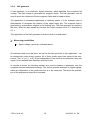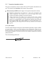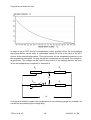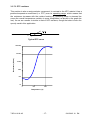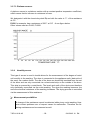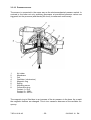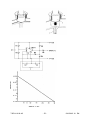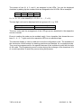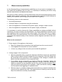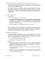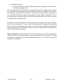
1
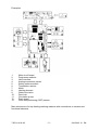
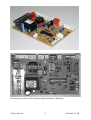
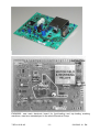
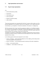
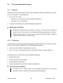
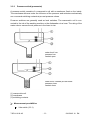
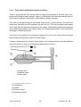
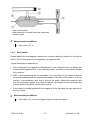
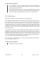
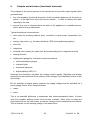
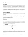
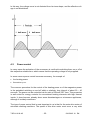
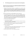
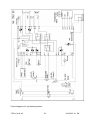
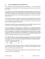
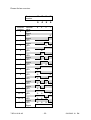
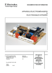
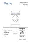
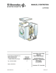
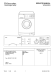
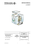
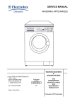
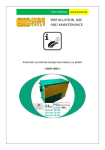
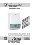
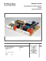
TRAINING PAPER
HOUSEHOLD APPLIANCES
WITH
ELECTRONICS
© AEG Hausgeräte GmbH
Muggenhofer Straße 135
D-90429 Nürnberg
Germany
Fax +49 (0)911 323 1420
TSE-N
Edition:
10.00
Publ. No.:
599 50 85 10
EN
FAULT FINDING
AND
DIAGNOSIS
IN
HOUSEHOLD
APPLIANCES
WITH
ELECTRONICS
Contents
1.
Why do we use electronic components in household appliances
3
2.
General functions of electronics in household appliances
4
3.
Input parameters and sensors
9
3.1
Typical input parameters
9
3.2
The most important sensors
10
3.2.1
Switch
10
3.2.2
Thermostat
10
3.2.3
Pressure switch (pressostat)
11
3.2.4
Flow switch (differentisl pressure switch)
12
3.2.5
Reed switch
13
3.2.6
Hall generator
14
3.2.7
Temperature-dependent resistors
15
3.2.7.1 NTC resistor
15
3.2.7.2 PTC resistor
17
3.2.7.3 Platinum sensor
18
3.2.8
Humidity sensor
18
3.2.9
Tachogenerator
19
3.2.10 Pressure sensor
20
3.2.11 Optical sensor
22
4.
Outputs and actuators (functional elements)
23
4.1
Power supply devices
24
4.1.1
Relay
24
4.1.2
Triac and thyristor
24
4.2
Power control
25
4.2.1
Phase control
26
4.2.2
Pulse width modulation
28
5.
Fault finding approach (Service manuals and circuit diagrams)
30
6.
Use of integrated service test programmes
32
7.
Measurement possibilities
35
TSE-N 10.00 AS
-2-
599 50 85 10 EN
1.
Why do we use electronic components in household appliances?
Electronic controls of different complexity have become part of our daily lives. One cannot imagine household appliances without them any more. But the addition “electronic”
is sometimes used quite loosely. The term often appears in connection with simple appliances, which probably only use one electronic component. We want to use the term
only when the appliance contains more complex electronic circuits, which are essential
for its use.
There are many good reasons for the use of electronic circuits. They offer many advantages in comparison with electromechanical controls:
• Programme parameters can be controlled more exactly.
• The functioning of the appliance can be optimised by the use of fuzzy logic.
• Both lead to a reduced consumption of energy, water and chemical products and
therefore reduce strain on the environment.
• Programmes are more flexible and can be adjusted to a new situation. The Electrolux
group plays the role of a forerunner: an update function, for example, was introduced
for the first time ever in an automatic washing machine of the Electrolux Group. Here
the software of the electronics is updated in order to adjust the appliance to the most
modern technical standards as well as to the actual conditions: e.g. new detergents,
new textiles, but also changed washing habits.
• The user is relieved from having to deal with the operation of the appliance and having to choose and enter individual parameters (e.g. washing temperature, spin
r.p.m.). He merely has to enter his “wishes”.
• Improved manufacturing possibilities with consecutively reduced manufacturing
costs.
• Reduced wear and tear due to the absence of moving contacts.
TSE-N 10.00 AS
-3-
599 50 85 10 EN
2.
General functions of electronics in household appliances
Electronic components are mainly used for the following functions:
• as a user interface (Input/output electronics) which:
o transfers the user input to the appliance, e.g. the chosen programme, the desired
temperatures, the kind of washing, the degree of soiling, cooking time, etc.
o again displays the relevant functional parameters, like programme steps, warning
messages, for the user’s information.
• as a control element: the exact programme step is determined as a function of to the
user input as well as of the measured functional parameters (e.g. switch positions,
temperature, water level, motor r.p.m., etc.). The output signals are used for:
o triggering the actuators, if necessary via a power electronics
o displaying the functional states via the user interface.
• as a power electronics which ensures the power supply of the actuators.
USER
INPUT/
OUTPUT
ELECTRONICS
CONTROL
POWER
ELECTRONICS
ACTUATORS
(MOTOR,
VALVE,
HEATING,
ETC.)
SENSORS
TSE-N 10.00 AS
-4-
599 50 85 10 EN
Depending on the complexity and construction of the appliance these functions can be
housed on a single or on separated components.
In the following it is not intended to explain the processes that take place inside an electronics. In general there are no accessible measuring points. Details with regard to this
fall in the domain of specialized suppliers and will not be found in the service documentation of the appliance.
For us the electronic circuit will remain a single spare part and is treated like a “black
box“. In no case will individual components on a board be exchanged. This is also not
allowed for reasons of safety. The implementation of unsuitable components could
cause for example fires.
We want to investigate what happens around the electronics and measure inputs and
outputs, if that is possible, as well as the functioning of the components, which communicate with the electronics.
With the help of these techniques, faults can be isolated more closely so that only those
parts are exchanged which are really necessary.
TSE-N 10.00 AS
-5-
599 50 85 10 EN
Examples:
1.
2.
3.
4.
5.
6.
7.
8.
9.
10.
11.
12.
13.
Main circuit board
Programme selector
User interface
Analogue pressure sensor
Safety pressure switch
Temperature sensor
Motor
Heating element
Water inlet valve
Door lock
Circulation pump
Drain pump
Drum self-positioning (DSP) sensor
Main electronics of a top-loading washing machine with connections to sensors and
functional elements
TSE-N 10.00 AS
-6-
599 50 85 10 EN
EAC electronics used in AEG automatic washing machines, 1998 series
TSE-N 10.00 AS
-7-
599 50 85 10 EN
EWM2000: new main electronic board for front-loading and top-loading washing
machines, used as a standard part in the whole Electrolux Group
TSE-N 10.00 AS
-8-
599 50 85 10 EN
3.
Input parameters and sensors
3.1
Typical input parameters
Are:
• switch states (binary codes)
• temperature
• level (water, foam)
• motor revolutions
• degree of residual humidity
• water turbidity
These input parameters are measured with the help of sensors, which make use of the
physical dependency of an electrical value from our parameter. This is often achieved in
several steps, e.g. temperature à electrical resistance of the sensor à voltage drop.
With the concept of the “fuzzy“ logic the programme makes use of additional parameters, which are not measured but “estimated”via other input parameters or their variation
over a certain amount of time. In this case the dependency of the two values cannot be
exactly defined. The connection can be more intuitively felt.
The amount of crockery in a dish-washer, for example, is determined via the time that is
needed for the water to heat up; however this time also depends on other factors like the
material of the crockery.
In the following please find some examples for such values:
• amount of washing – via the absorbing behaviour of the washing, which really means
via the time gradient of the water level
• amount of crockery – via the heating-up speed, meaning via the water temperature
• soiling – via the water turbidity
• Unbalance – via fluctuation of motor r.p.m.
TSE-N 10.00 AS
-9-
599 50 85 10 EN
3.2
The most important sensors
3.2.1
Switches
Switches are the most frequently used sensors. System states are reported to the electronics via switches. The switches are:
• set by the user, either
o directly (e.g. I/O switches, various selector switches) or
o indirectly (e g. door switches)
• or they are activated by the system during the programme.
Ø Measuring possibilities
• Resistance measurement (continuity): this type of measurement provides a
way to find out if the switch is in its expected switching state (open or closed).
• Voltage measurement: is another way to detect the switching state; voltage is
present with the switch in its open state.
3.2.2
Thermostat
A thermostat is an electromechanical temperature switch that opens or closes an electrical circuit at a certain temperature. The switching temperature is:
• either set mechanically à temperature control or
• set to a fix value à temperature limiter (is generally used as a safety element).
According to their construction we can distinguish between:
• bimetal thermostat
• metal-rod expansion thermostat
• liquid-expansion thermostat
• vapour condensation thermostat (used in refrigeration)
Ø Measurement possibilities
• like switch (3.2.1). Please refer to the switcing temperatures in the service
manuals in order to determine the expected switching state.
TSE-N 10.00 AS
- 10 -
599 50 85 10 EN
3.2.3
Pressure switch (pressostat)
A pressure switch consists of a manometric cell with a membrane fixed on the inside.
The membrane deforms under the influence of the pressure and activates mechanically
one or several switching contacts at pre-set pressure values.
Pressure switches are generally used as level switches. The manometric cell is connected to the tub of the washing machine or the dishwasher via a hose. The rising of the
water column causes the air pressure in the hose to rise.
water level low
pressure low
contact open
water level reaches pre-set value
pressure rises
contact close
(1) manometric cell
(2) membrane
(3) switching contacts
Ø Measurement possibilities
• Like switch (3.2.1).
TSE-N 10.00 AS
- 11 -
599 50 85 10 EN
3.2.4
Flow switch (differential pressure switch)
There is a physical law that can be used to detect the existence of the flow, like for example the flowing of water through a pipe. It is Bernoulli’s law that says that the sum of
flow pressure and static pressure in a flow always remains constant.
If the flow is directed through a contracted cross section (Venturi nozzle), the local flow
speed and therefore the flow pressure as well will rise. The static pressure decreases
and is less than the pressure upstream of the nozzle. When both pressures are directed
into a differential pressure cell via thin tubes, the resulting deformation of the membrane
will trigger a switching process.
If the flow is non-existent, the pressures upstream of and in the Venturi tube are equal
and the differential pressure switch will open again.
If water is heated with the help of a flow heater, the heating element must be switched
via a flow switch, in order to avoid heating when there is no flow.
no water flow
pressures equal
contact open
(1) differential pressure cell
(2) membrane
(3) needle
(4) Venturi nozzle
(5) switching contact
TSE-N 10.00 AS
- 12 -
599 50 85 10 EN
water flow existent
static pressure in nozzle lower than upstream
contact closes
Ø Measurement possibilities
• Like switch (3.2.1).
3.2.5
Reed switch
Reeds made from ferromagnetic material are used as switching contacts for this type of
switch. The switching process is triggered by a magnetic field.
Typical examples for applications:
• Salt or detergent level gauge for dishwashers: in the container there is a floater with
a permanent magnet which, in the desired position, activates a reed switch outside
the container.
• DSP = drum positioning aid for top-loaders: the reed switch of the sensor is kept in
its normal closed position by a permanent magnet; if the door of the drum is in its top
position, a ferromagnetic strip, that is fixed to the pulley, affects the magnetic field
and the reed switch opens. It provides the gauge input signal for the electronics and
helps to position the drum via the motor control.
• Door switch in cooling appliances: the magnet is in the door and the reed switch is in
the door frame.
Ø Measurement possibilities
• Like switch (3.2.1); can be triggered with an external magnet.
TSE-N 10.00 AS
- 13 -
599 50 85 10 EN
3.2.6
Hall generator
A Hall generator is an electronic signal generator, which amplifies the so-called Hall
voltage. The Hall voltage is generated by magnetic fields. The Hall generator can be
used to prove the existence of these magnetic fields and to measure them.
The application in household appliances is relatively simple: it is for example used in
dish-washers to recognize the rotation of the upper rotary arm. The magnetic field is
generated by a permanent magnet in the flushing arm. The Hall generator is located in
the door. When the arm passes by the door the output voltage is at 4-5 V, otherwise at
0-1 V.
This application of the Hall generator is similar to that of a reed switch.
Ø Measuring possibilities
• Signal voltage: values are indicated above.
All switches listed up to this point, as well as the Hall generator in this application, can
be categorized under binary sensors. All of them simply report two states to the electronics: “yes“ or “no“ (1 or 0). Quite independent of the value to be measured, they only
report if a pre-defined state has been reached or not.
In contrast to these, the following sensors are used to measure a parameter over the
complete relevant measurement range. The sensor provides analogue or digital signals,
which are dependent on the parameter that is to be measured. Therefore the possibilities of the programme layout are increased.
TSE-N 10.00 AS
- 14 -
599 50 85 10 EN
3.2.7
Temperature-dependent resistors
This group of temperature sensors contains NTC and PTC resistors and platinum sensors. The collective term thermistor is also used for these resistors.
Ø Measurement possibilities (which apply to all temperature-dependent resistors)
• Resistance measurement: the measured ? ? value must correspond to the
ambient temperature; when heated up, the value will change (exact values
can be found in tables or graphs in the service manual)
• Voltage measurement: the voltage can be measured at the sensor contacts
or, better still, at the respective connector on the electronics circuit board. The
sensor is in a voltage divider circuit. Therefore the expected value will be below the signal voltage. With a signal voltage of 5 V we can expect about 2-3 V.
When heated up, the voltage at the NTC will drop, whereas it will increase at
the PTC.
3.2.7.1 NTC resistor
The NTC resistor belongs to the group of semiconductors (generally a mixture of different metal oxides). It has a very high resistance at low temperatures. When the temperature increases, more electrons are released from their bonds. As a result the electrical resistance decreases. The resistor therefore has a negative temperature coefficient
(abbreviated NTC).
This is the switching symbol used:
ϑ
TSE-N 10.00 AS
- 15 -
599 50 85 10 EN
A typical curve looks like this:
In order to use an NTC sensor for temperature control, a bridge circuit, like the simplified
one shown below, can be used. A controllable resistor RT is set to the value of the NTC
sensor at the desired temperature. This can be done via the temperature selector or via
the programme electronics. As long as the two resistances are not equal, the voltage U1
is generated. This voltage can be used for the control of the heating element. As soon
as the set temperature is reached, U1 becomes 0.
RT
R1
U1
RNTC
R1
ϑ
U0
If we want to actaully measure the temperature for an indicating gauge for example, we
can do this by measuring the voltage drop.
TSE-N 10.00 AS
- 16 -
599 50 85 10 EN
3.2.7.2 PTC resistors
This resistor is also a semiconductor component. In contrast to the NTC resistor it has a
positive temperature coefficient (i.e. PTC) over its operating range, which means that
the resistance increases with the resistor heating up (operating range is stressed because the overall temperature variation is more complicated, as shown in the graph below). Its use as a sensor is similar to that of NTC resistors, though the latter is more frequently used in this application.
ϑ
Typical PTC curve
1000000
Resistance (Ohms)
100000
10000
1000
100
10
0
100
200
Temperature (°C)
TSE-N 10.00 AS
- 17 -
599 50 85 10 EN
3.2.7.3 Platinum sensors
A platinum sensor is a platinum resistor with a constant positive temperature coefficient,
which means that its increase in resistance is linear.
We designate it with the chemical symbol Pt, and with the value in ? ? of the resistance
at 0°C.
Pt500, for example, has a resistance of 500 ? at 0°C à see figure below.
Other values used are Pt100, Pt1000.
3.2.8
Humidity sensor
This type of sensor is used in tumble driers for the measurement of the degree of residual humidity in the washing. The drum is connected to the appliance earth (back side of
the case) via a carbon feeler. The ribs of the drum are electrically insulated from the rest
of the drum and are only connected via a sheet-metal strip on the outside of the drum.
This strip is scanned by a metal brush. The brush and earth of the device are therefore
only electrically connected via the moist washing. The dryer the washing becomes, the
more the electrical resistance of the washing increases. The drying process is controlled
via the measurement of this resistance.
Ø Measurement possibilities
A change of the resistance cannot be detected without any moist washing. However contact problems are a frequent cause for malfunction. Therefore the following resistances can be measured as well:
TSE-N 10.00 AS
- 18 -
599 50 85 10 EN
• Contact resistance between the ribs of the drum and the input from the scanning brush on the electronic circuit board.
• Contact resistance between drum and case.
• Insulating resistance between ribs and drum.
3.2.9
Tachogenerator
This generator is used to measure the motor r.p.m.. The tachogenerator is firmly connected to the motor shaft. In a coil, that rotates in a magnetic field, a voltage is generated which is proportional to the revolutions. The generator can be constructed as:
• DC tachogenerator, that takes the voltage from a commutator;
• AC tachogenerator: this type is nowadays more frequently used because of its simpler construction: it does not need any commutator, and the layout can be inverted,
i.e. rotating permanent magnet and fixed coil.. For this type the frequency of the alternating voltage is also proportional to the r.p.m. In the digital circuits used on most
control electronics, the frequency measurement is more convenient and more exact
than the measurement via the voltage.
Ø Measurement possibilities
• A small voltage can already be measured while turning it by hand.
• The resistance of the coil can be measured.
TSE-N 10.00 AS
- 19 -
599 50 85 10 EN
3.2.10 Pressure sensor
The sensor is connected in the same way as the electromechanical pressure switch. In
contrast to the latter not only switching processes at pre-defined pressure values are
triggered, but the pressure (and thereby the level) is measured continuously.
1
2
3
4
5
6
7
8
Air intake
Membrane
Coil
Oscillator ( electronics )
Magnetic ring
Spring
Adjusting screw
Connection plug
Contact 1 = Out
Contact 2 = GND
Contact 3 = 5V DC
The magnetic ring is lifted due to an increase of the air pressure in the hose. As a result
the magnetic features are changed. This in turn causes a decrease of the oscillator frequency.
TSE-N 10.00 AS
- 20 -
599 50 85 10 EN
TSE-N 10.00 AS
- 21 -
599 50 85 10 EN
Ø Measurement possibilities
• It is not possible to measure the frequency using a simple multimeter.Even
with multimeters having this possibility, interferencve with the line frequency
makes the measurement difficult.
• The existence of an output voltage may be a first indication that the component is working. But as this sensor is a standard component frequently used,
“check by exchange”, though generally not advisable, is a usable method.
3.2.11 Optical sensors
This sensor for example is used in dishwashers as a turbidity sensor.
In a component, through which water is flowing, an LED and a photodiode are positioned opposite each other. When the water is turbid, the light, that is emitted by the
LED, is dimmed when it reaches the photodiode. The output voltage of the photodiode is
reduced proportionally. On the basis of this voltage the electronics estimates the degree
of soiling of the crockery or the residue of detergent respectively. With the help of this
information it is able to decide on the following programme required to obtain a satisfactory rinsing result.
It is important to note that the output voltage would slowly decrease over time due to
deposits at the sensor walls. In order to prevent this, the sensor that is used in Electrolux
dishwashers is calibrated at the end of each cycle during the last rinsing run. The input
voltage is slowly increased during this process – this is possible in the range from 6 to
11,4 V. The result is that the output voltage in this progamme step is at a constant 4,3 V.
This value signals to the electronics that the water is clear.
Note: if the sensor is calibrated in the air – which is the case during the service checks –
the output voltage must be at 3,5 V.
Ø Measurement possibilities
• Voltage measurement (see above)
TSE-N 10.00 AS
- 22 -
599 50 85 10 EN
4.
Outputs and actuators (functional elements)
The purpose of the control process in the electronics is to provide output signals which
guarantee that
• first: the actuators (functional elements) of the household appliance do the work required – at the right time and in the correct manner – in order to achieve the result
required by the user.
• second: the user is informed about the state of the appliance in a suitable manner,
and is warned of any malfunction.
Typical outputs and consumers are:
• drive motor for washing machine drum, circulation or drain pump, compressor, fan,
etc.
• step-by step motor, e.g. for water distributor, DPS (drum positioning system)
• door lock
• magnetron
• solenoid valve (usually for water inlet, but occasionally also in refrigerant circuits)
• heating element
• displays and gauges for functional controls and alarms
o electromechanical gauges
o indicator lights
o acoustical indicators
o digital displays (LED, LC)
Generally the electronics provides low voltage control signals. Signalling and display
elements can sometimes be driven directly at this voltage, if the absorbed current is also
low enough.
But for actuators of higher power however, the supply voltage must be switched via a
power supply device. Such components are:
• relays
• triacs
This is an essential difference to appliances with electromechanical timers. In these
units the complete working current runs via timer contacts. (Note: triacs or relays are
often positioned on the main board, so the line voltage can be measured at the outputs.
This is however not the working voltage of the electronics.)
TSE-N 10.00 AS
- 23 -
599 50 85 10 EN
4.1
Power supply devices
4.1.1
Relays
A relay is an electromechanical power supply device. The control voltage is connected
to the relay coil, often via a triac, because the coil absorbs a relatively high current. An
electromagnet closes the relay contact(s). The working current of a consumer (motor,
heating element, etc.) is directed via these contacts.
Relays are used to supply consumers of higher power, but also if safety standards require switching to be done by actual contact opening. Both conditions apply mainly to
heating elements.
4.1.2
Triac and thyristor
Both components are semiconductor elements and belong to the group of the controllable diodes.
A controllable diode is triggered by a current pulse at the gate. This means that it is
brought into a conducting state. The triggering point can be moved within a half-wave
with the help of an adjustable resistor.
The thyristor is only controllable in one current direction and provides therefore a pulsating current.
The triac is basically comparable with two thyristors that are switched in an antiparallel
way. It is controllable in both current directions and uses both half-waves of the alternating voltage. It is for this reason that the thyristor is preferably (we can say almost exclusively) used for power switching and control.
Triac symbol
Gate
If the triac is used to supply the working voltage to the actuator – that means not to control it – the circuit always contains a zero-voltage detector. This detector makes sure that
the trigger pulse will always be generated when the supply voltage sine wave is crossing
the zero line.
TSE-N 10.00 AS
- 24 -
599 50 85 10 EN
In this way, the voltage curve is not distorted from its sinus shape, and the effective voltage is not diminished.
1st half-wave
4.2
2nd half-wave
Power control
In many cases the activation of the consumers is confined to switching them on or off at
the respective suitable time, which means that the operating voltage is only supplied.
In some cases a power control becomes necessary, for example of:
• the heating power
• the motor r.p.m.
The common procedure for the control of the heating power or of the magnetron power
is the periodical switching on and off within a relatively long interval of about 20 – 40
seconds. The power can be controlled via the ratio of ON and OFF time. This procedure
is well suited for energy controls for conventional heating elements with high thermal
inertia. It does however already show some disadvantages on microwave appliances,
although it is widely used there.
The type of power control that is most important to us is that for the main drive motor of
automatic washing machines. The speed of this drive motor must cover a very wide
TSE-N 10.00 AS
- 25 -
599 50 85 10 EN
range – from maybe 25 r.p.m. in the wool or hand wash programme to the maximum
spin r.p.m. of 1800. The speed range can be chosen by adding or removing field coils.
For a continuous, and fast-reacting, control within a range, we can use:
• phase control
• pulse width modulation
Basically the two procedures are no different from the clocking which was mentioned
before. Only the clocking interval is shortened considerably: to a half-period of the supply frequency (i.e. 10 ms) for phase control, and to 50 – 60 µs for pulse width modulation.
4.2.1
Phase control
This procedure “cuts off“ parts of the symmetrical sinus curve with the help of electronic
components like a triac. As mentioned in 4.1.2, a control circuit can supply a trigger
pulse at the triac’s gate either at zero crossing (i.e. at 0° phase angle), or at any phase
angle between 0° and 180°.
Increase of the phase angle at which the trigger pulse occurs will lead to a reduction of
the effective (RMS) voltage, and hence to a progressive power reduction. The major
disadvantage of the phase control is that the current curve deviates significantly from its
original sinus shape. This means that harmonics – i.e. oscillations with frequencies that
are multiples of 50 Hz - interfere with the supply frequency of 50 Hz. The harmonic currents cause harmonic voltages in the electrical supply network, which significantly impair
not only the power supply but also the other consumers that are connected to it.
The phase control has its problems at higher power levels because:
• more recent regulations prescribe tougher limits for harmonic voltages
• these regulations must nowadays be complied with; otherwise you will not be allowed
to bring the appliance on the market in the EU (compliance with the regulations is
visually indicated by the CE symbol on the appliance)
• the disturbances caused by harmonic voltages have become more of a problem particularly for appliances with electronic controls. Voltage spikes and high frequencies
can cause disturbances in these circuits, if they exceed the immunity levels imposed
by regulations.
If this type of control is used, relatively extensive measures for interference suppression
are needed.
TSE-N 10.00 AS
- 26 -
599 50 85 10 EN
Phase control using a triac
trigger pulse in first part of half-wave
à high RMS voltage
à high power
trigger pulse at peak of half-wave
à half RMS voltage
à half power
trigger pulse towards end of half-wave
à low RMS voltage
à low power
TSE-N 10.00 AS
- 27 -
599 50 85 10 EN
4.2.2
Pulse width modulation (PWM)
This procedure disconnects the motor with a high frequency (16 to 20 kHz) from the
power supply. The relation of switching on and off time can be varied via the microprocessor. The name PWM = pulse width modulation stems from the fact that the width of
the individual impulses changes. Due to this principle the motor speed can be controlled
over a very wide range. More important, the high pulse frequency leads to short reaction
times, which allows the use of very high spin speeds of up to 1800 r.p.m. When using
this type of control, the motor is fed with pulsating direct current.
High pulse width
Low pulse width
TSE-N 10.00 AS
- 28 -
599 50 85 10 EN
Power supply
Control electronics
Code for direction of drum
movement and and for field
tapping
Motor
electronics
PTC temperature check
13 V for relay
PWM pulse
tacho pulse
Motor signal
Signal transmission between control electronics EWM3000 und motor electronics for
automatic washing machines using pulse-width modulation
TSE-N 10.00 AS
- 29 -
599 50 85 10 EN
5.
Fault finding approach (service manuals and circuit diagrams)
We would like to point out how important it is to approach fault finding systematically and
logically. It is of major importance to use the product documentation, that means the
service manuals and the circuit diagrams.
• Please do always identify the appliance unmistakably when you take the order
(PNC/E Nro. and also Series No./F No. if possible). Service manuals can be prepared and taken with you. This has always been desirable but is of crucial importance for appliances with integrated diagnosis programmes, because these programmes can only be used and interpreted correctly with the help of the documentation.
The basics of fault finding for conventional appliances remain mainly valid.
• At first please test if there is a fault at all. In many cases the appliance works according to its specifications but the customer has got other expectations in mind –
they may be justified or not. This is often the case with cooling and freezing appliances. Always try to convince the customer with arguments and to refer him to customer services if necessary. Never exchange parts or even the whole appliance. This
only leads to costs without solving the problem.
• If there is a fault, localize the faulty circuit
o via the fault code, if available
o if the code is not available, use the symptoms of the fault, and check on the wiring
diagram what might cause such symptoms
• do not just exchange components in this circuit, but check the complete path of the
current with reference to the circuit diagram by measuring (see section 6.)
• search for commonplace faults first:
o correct connection
o contacts (a very frequent cause for faults!), pay special attention to plug connections of electronics – you may need to physically move them
o hose connections, possibly blocked hoses
• activate components directly, if service programmes allow this
TSE-N 10.00 AS
- 30 -
599 50 85 10 EN
Circuit diagram of a top loading washer.
TSE-N 10.00 AS
- 31 -
599 50 85 10 EN
6.
Use of integrated service programmes
If the appliances are fitted with integrated service programmes – this is more and more
the case with the newer appliances – these programmes should be your first choice for
fault finding.
A first localization of the fault can be achieved via the displayed fault code. This has the
advantage of saving yourself time during the fault finding. Displaying the fault codes
stored in the machines memory should always be the first action, checking the configuration code, if applicable, the second (a wrong configuration code can lead to quite misleading faults)
The fault code provides an “objective“ statement about a real diagnosed fault. This may
be in contrast to the user’s assessment which can be subjective. The user may also only
see a consecutive fault. (this shall not mean that you can’learn a lot about the fault process by asking the user specific questions).
Additionally the customer service programmes offer the possibility to trigger individual
circuits directly, which enables you to localize the fault more quickly.
For some appliances, like dishwashers, it is possible to run a standardized customer
service test programme. This is of importance, given that the working programmes of the
appliance are created in an adaptive way and therefore have no fixed order. The customer for example has a complaint, that the appliance does not pump the water out after
the pre-rinse. This could be caused by a faulty appliance, but it could also be the normal
operation because the turbidity sensor did not detect any significant soiling. Both cases
can only be distinguished with the help of the test programme.
If the appliance does not have a display which indicates the fault code in clear writing
(e.g. “C2“), the LEDs on the panel can be used to display fault and configuration codes.
The display has to be done in binary code because an LED has only got two states –
ON or OFF. These are the definitions:
§ OFF
(LED extinguished) for:
§ ON
(LED lit)
for :
0
1.
16 characters can be indicated with a group of 4 LEDs: the numbers 0 to 9 as well as
the letters A to F (these 16 characters are the “numbers“ of the hexadecimal system,
that is the counting system with the base 16).
The following table also displays the signals that can be measured when you suspect
that some LEDs are not functioning.
TSE-N 10.00 AS
- 32 -
599 50 85 10 EN
Please find an overview:
Dual
number
Decimal
number
0
1
2
3
4
5
6
7
8
9
10 – A
11 – B
12 – C
13 – D
14 – E
15 - F
TSE-N 10.00 AS
Decimal
value
LED
Signal
LED
Signal
LED
Signal
LED
Signal
LED
Signal
LED
Signal
LED
Signal
LED
Signal
LED
Signal
LED
Signal
LED
Signal
LED
Signal
LED
Signal
LED
Signal
LED
Signal
LED
Signal
23
22
21
20
ê
ê
ê
ê
8
4
2
1
¤
¤
¤
¤
¤
¤
¤
¤
¤
¤
¤
¤
¤
¤
¤
¤
¤
¤
¤
¤
¤
¤
¤
¤
¤
¤
¤
¤
¤
¤
¤
- 33 -
¤
599 50 85 10 EN
The powers of two (8, 4, 2, and 1) are assigned to the LEDs. You get the displayed
character by adding up the numbers that are assigned to the lit LEDs. As an example:
8
¤
4
¤
2
1
¤
8 + 4 + 4 = 13, or the letter D (A = 10, B = 11, ..., F = 15).
The two-digit code can be displayed with two groups of 4, e.g. “C2“:
8
¤
4
¤
2
1
8
4
2
¤
1
The error codes and the arrangement of the LED groups are described in the respective
service manuals.
Errors in reading the code can be avoided easily. Use a template, that shows the numbers 8 – 4 – 2 – 1 right next to the respective LEDs or an adhesive tape.
The identical display is used to read and to set the configuration code. The hardware of
the electronics circuit boards for washing machines are identical for a complete series.
They must be programmed for the special features of the individual model with the help
of this code. The programming must be done during the exchange of the board and it is
of crucial importance to avoid any errors during this process.
TSE-N 10.00 AS
- 34 -
599 50 85 10 EN
7.
Measurement possibilities
In the following listing of measurement possibilities we do not want to investigate in further detail the possibilities that you have in a workshop or laboratory and when using
special measurement and display instruments.
We want to confine ourselves to the measurements that can be performed quickly at the
location with a common multimeter. This one measurement instrument should always be
taken by the customer service engineer and made use of regularly.
The following values can be measured:
§ functional parameters
§ electrical values of components using the multimeter:
§ when the appliance is connected to the power supply: voltages, maybe currents
§ when the appliance is separated from the power supply: resistances
It is necessary to mention that not all of these possibilities are always available without
restrictions. In some countries, like Great Britain, it is strictly prohibited to measure at an
open appliance that is connected to the power supply. Even when there are no regulations that restrict the measurements, they must always be performed in a manner which
guarantees the absolute safety of the customer service engineer and that of the environment.
What can be measured?
1. Power supply of the appliance, that means:
§ Does the voltage at the connection of the appliance have the correct value)?
§ Is the appliance connected in a correct manner?
§ Is there any voltage at the connection point inside the appliance?
2. Voltage supply to the components:
§ after the potentially faulty component has been identified, choose an operational
state in which a power should be supplied to the component. Now the voltage can
be measured at the terminals of this component. If the voltage is existent, the
defect must be somewhere in the component itself.
§ If no voltage can be measured, you need to follow the connection cables and
measure the voltage at more suitable positions. Testing in this way, damage to
cables or contacts can be identified, and the fault can be further localized. Note:
using the service manual and circuit diagram, make sure that the missing voltage
is not a result of the triggering of a safety function.
§ With the help of a suitable measurement instrument (e.g. snap-on ammeter) the
current can be measured as well. The measurement of working currents with the
help of a multimeter is usually not practicable.
TSE-N 10.00 AS
- 35 -
599 50 85 10 EN
3. Signal voltages at inputs and outputs of the electronics as well as at sensors
§ At temperature-dependent resistors: you can expect values that are roughly half
of that of the signal voltage; when heated up, the voltage must change its value in
the same direction as the resistance.
§ At all types of switches (reed switch, pressure switch, thermostat, flow switch,
etc.): voltage = zero for closed switch, signal or operating voltage for open switch.
If poosible, induce change of the switching state in order to measure both states.
§ Tachogenerator: a voltage of a few volts can be generated by turning the generator by hand.
4. Functional parameters
§ Temperatures
o For cooking appliances: oven temperature.
o For cooling and freezing appliances: primarily temperatures inside, additionally
temperatures at the refrigerant circuit. For measurements in the inside attention needs to be paid that not the air temperature but the average storage
temperature is measured à e.g. in a glass of water that has already been in
the fridge for about 30 minutes.
o For different appliances: switching temperatures of thermostats.
§ Time / programme steps: with reference to the service manual it needs to be determined and measured, if the programme steps take place in the prescribed order and at the prescribed time. Choose a customer service test programme, if
possible, because other programmes are variable in their order.
5. Resistances, particularly of:
§ components (heating elements, motor coils, coils of solenoid valves): it needs to
be measured that the resistance corresponds to the prescribed value. Generally
this value can be found in the service manual. Even if you do not know the exact
value, the measurement can provide important clues:
o a very small value indicates a short circuit
o a very high value indicates an interruption
§ sensors:
o for temperature-dependent resistors (NTC, PTC, Pt..): tables or graphs can
generally be found in the manual. In any case the resistance must show the
change that is expected when it is heated up, for example by your hand: a decrease for NTC, an increase for PTC or Pt.. .
Alternatively temperature-dependent resistors can be simulated with the help
of a resistor decade.
o For switches: 0 (or a very lowl value for a closed switch), ∞ (or a very high
value) for an open switch. If possible, induce a change of the switching state
in order to measure both states.
TSE-N 10.00 AS
- 36 -
599 50 85 10 EN
§ Wiring and contacts:
o must be checked for a small resistance. Move the contacts in order to find out
if the value changes or not.
For all measurements of resistances you should measure the complete wiring, if possible. However this may depend on the accessibility. Remove, for example, the plug from
the electronics and measure from there. If the values are within the normal range, you
have checked the wiring as well as the component in one single measurement. Only if
the measurement values are different from the prescribed values, you have to continue
to approach the component itself.
At this point it is also important to note that there are no simple measurement possibilities for some components. In some cases the checking by exchanging is recommendable, e.g. for the analogue pressure sensor. If you choose this method of testing please
note the following: if you find that the component was not faulty after all, please put the
old part back into its former place.
Please remember: it does not take much time to keep a record of the measurement
results and the measurement conditions. Such records can be of great help if the case
develops into something much more complicated later on or if you need to respond to
questions or complaints.
TSE-N 10.00 AS
- 37 -
599 50 85 10 EN