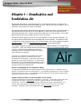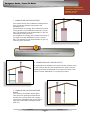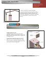
1
HD IEGSHI GENFEF RI C
L ®B BO OI LI E
’ SI E GN UC IYD C
E OPMOM
WEERRC- FI AI N
L ER RS
Up to 87%
Thermal Efficiency
w w w . L o c h i n v a r .c o m
Dear Design-Build Contractor / Project Manager / Design Engineer,
At Lochinvar, we have long recognized the importance of innovation to any
product or service. Those who share in this business also face the challenge
of meeting constantly changing needs and energy efficiency demands.
The designer’s guide you are now holding has been designed to make it more
convenient for you to select the perfect Lochinvar boiler for your projects
and provide correct specifications for your teams.
All information has been organized and presented in a succinct, easy-to-use
manner, so you can use and share information confidently and with minimal
effort.
However, it is important to remember that this guide is not intended to
replace our installation manual. Installers should refer to our installation
manual for specific installation instructions and more detail. This guide will
make regular reference to other documents like the Installation & Operation
Manual that are available on the Lochinvar website, www.Lochinvar.com.
We hope this manual will make your work easier and more productive.
Thanks again for specifying the Lochinvar family of quality standard and
custom-built water heaters and boilers.
Sincerely,
Designer’s Guide / Power-fin Boiler
LOCHINVAR CORPORATION
300 MADDOX SIMPSON PKWY
LEBANON, TN 37090
www.lochinvar.com
Table of Contents
1
Combustion Air …………..…..……………………… Page 5
2
Venting
3
Gas ….….…………….……………….………………… Page 21
4
Water …..……………………..……………………….. Page 23
5
Electricity & Controls ……………………………….. Page 28
6
Other Details ..……………………………………….. Page 33
7
Appendix A ….……..…………………………………. Page 36
8
Appendix B …………………………………………… Page 41
….…………………………………………….. Page 8
.
3
Designer’s Guide / Power-fin Boiler
LOCHINVAR CORPORATION
300 MADDOX SIMPSON PKWY
LEBANON, TN 37090
www.lochinvar.com
At Lochinvar, we know that designing a boiler is hard work. Designing a boiler system is
no picnic either. Demands for greater efficiency and elaborate system control have
made systems more complex.
This designers guide will break down the system requirements that match the Power-fin
boiler to assure safe operation, highly efficient heating and long life.
There are five major elements of boiler system design:
Combustion Air
(See page 5)
Air
Venting
(See page 8)
Gas
Electricity
&
Controls
Venting
(See page 21)
Water
(See page 23)
Water
Gas
Electricity &
Controls
(See page 29)
Plus many other important details:
Locations
(See page 34 for “Location of Unit”)
Available Options
(See page 35 for “Options”)
High Altitude Requirements
(See page 35 for “High Altitude Applications”)
Suggested Piping Diagram
(See Appendix Section “A”)
4
Designer’s Guide / Power-fin Boiler
LOCHINVAR CORPORATION
300 MADDOX SIMPSON PKWY
LEBANON, TN 37090
www.lochinvar.com
Chapter 1 – Combustion and
Ventilation Air
Everybody’s gotta breathe. Even boilers need air. Air seems easy enough. You stand in the
equipment room and you breathe comfortably, don’t you? Open a door. Open a window. This is
a big room. There’s lots of air in here for the boiler.
The average person inhales 400 to 500 cubic feet of air in a 24 hour period. A one million Btu/hr
boiler will draw 226.38 cubic feet of air every MINUTE! A 20 by 20 by 8 foot equipment room
holds 3200 cubic feet of air. That’s a volume of air to last you or me over six days. A one million
Btu/hr Power-fin will consume 3200 cubic feet of air in 14 minutes.
Therefore, a good, easy flow of clean air is 100% necessary for clean, efficient combustion. So,
we need to provide a permanent and uninterrupted flow of air to the boiler. The Power-fin boiler
is designed to receive combustion air by one of TWO methods. The boiler may draw combustion
air from the room or have the air ducted directly to the boiler from an exterior space.
This chapter explains the methods for “air from the room”. Chapter 2 explains “air ducted directly
to the boiler”. Again, this chapter lists several techniques to size the air openings that will deliver
room air. If there are other appliances in the room
requiring air, their air requirements must be including
when sizing the air openings.
Provisions for combustion and ventilation air must be
designed and installed in accordance with “Air for
Combustion and Ventilation”, of the latest edition of the
National Fuel Gas Code, ANSI Z223.1, (in Canada, the
latest edition of CGA Standard B149 Installation Code for
Gas Burning Appliances and Equipment) or applicable
provisions of the local building codes.
Air
NEGATIVE PRESSURE IN THE EQUIPMENT ROOM
It is important to NEVER have a negative pressure on the equipment room. Exhaust fans are
popular in equipment rooms to exchange the air. If the exhaust fan pulls air OUT, then a negative
pressure occurs in the room. The combustion and ventilation air must be sized to supply all the
equipment PLUS the air for the exhaust fan.
COMBUSTION AND VENTILATION AIR SIZING CALCULATIONS
The sizing calculations in this section are based on “Free Area”. The louvers or grill used on the
air openings must have a net free area equal to or greater than the value derived in the
calculations. The Free Area in a louver or grill is defined as the open, unblocked area. The
louvers, grills, mesh, blades, all will block a given amount of space in the louver’s overall
dimension. Consult the louver manufacturer for exact net free area of the louver.
5
Designer’s Guide / Power-fin Boiler
LOCHINVAR CORPORATION
300 MADDOX SIMPSON PKWY
LEBANON, TN 37090
www.lochinvar.com
1. COMBUSTION AIR FROM OUTSIDE
If air is taken directly from outside the building with no
duct, provide two permanent openings to the
equipment room:
(a) Combustion air opening, with a minimum free area
of one square inch per 4000 Btu/hr input (5.5 cm² per
kW). This opening must be located within 12" (30 cm)
of the bottom of the enclosure.
(b) Ventilation air opening, with a minimum free area of
one square inch per 4000 Btu/hr input (5.5 cm² per
kW). This opening must be located within 12" (30 cm)
of the top of the enclosure.
Did you Know?
THE POWER-FIN COMES WITH LOUVER CONTACTS AS STANDARD EQUIPMENT. THE CONTACTS
WILL OPEN AND CLOSE A MOTORIZED LOUVER ON EACH CALL FOR HEAT.
2. COMBUSTION AIR THROUGH DUCTS
If combustion and ventilation air is taken from the outdoors using
a duct to deliver the air to the equipment room, each of the two
openings should be sized based on a minimum free area of one
square inch per 2000 Btu/hr (11 cm² per kW) of input.
3. COMBUSTION AIR FROM INTERIOR
SPACE
If air is taken from another interior space,
each of the two openings specified above
should have a net free area of one square
inch for each 1000 Btu/hr (22 cm² per kW) of
input, but not less than 100 square inches
(645 cm²).
6
Designer’s Guide / Power-fin Boiler
LOCHINVAR CORPORATION
300 MADDOX SIMPSON PKWY
LEBANON, TN 37090
www.lochinvar.com
4. DIRECT OUTSIDE AIR, SINGLE OPENING
If a single combustion air opening is provided to bring
combustion air in directly from the outdoors, the opening
must be sized based on a minimum free area of one
square inch per 3000 Btu/hr (7 cm² per kW). This opening
must be located within 12" (30 cm) of the top of the
enclosure.
Caution
THE COMBUSTION AIR MUST BE FREE OF ANY CONTAMINANTS OR CHEMICAL FUMES. SALTS,
REFRIGERANTS AND SOLVENTS INTRODUCED INTO THE COMBUSTION PROCESS WILL RESULT IN
THE FORMATION OF CORROSIVE ACIDS THAT WILL DAMAGE THE APPLIANCE AND THE VENT.
COMBUSTION AIR FILTER
The Power-fin has a built-in air filter as standard
equipment. Located at the combustion air inlet, the air
filter is provided to help ensure clean air is used for the
combustion process.
The filter size on models 502-1302 is 16" x 12" x 1"
(40.6 cm x 30.4 cm x 2.5 cm) and on models 1501 2001 is 16" x 16" x 1" (40.6 cm x 40.6 cm x 2.5 cm).
You can find these commercially available filters at any
home center or plumbing supply store.
7
Designer’s Guide / Power-fin Boiler
LOCHINVAR CORPORATION
300 MADDOX SIMPSON PKWY
LEBANON, TN 37090
www.lochinvar.com
Chapter 2 – Venting
Venting is a difficult design element for the installation of a gas fired appliance. It has a variety of
choices, it has several available vent configurations, it has the important rules and regulations
that govern the installation and most important of all, it bears a requirement for human safety.
Warning
SPILLAGE OF FLUE PRODUCTS AND CARBON MONOXIDE EMISSIONS PRODUCED BY THE
COMBUSTION PROCESS CAN CAUSE SEVERE PERSONAL INJURY OR DEATH.
Lochinvar offers twelve different vent configurations on the Power-fin boiler to meet the building’s
requirements. There are six layouts or footprints across three different vent categories.
They are…
Vertical Vent with Air from the Equipment Room
Category I, Category II or Category IV
Vertical Vent with Air from the Rooftop
Category I, Category II or Category IV
Vertical Vent with Air from the Sidewall
Category I, Category II or Category IV
Sidewall Vent with Air from the Equipment Room
Category IV only
Sidewall Vent with Air from the Rooftop
Category IV only
Sidewall Vent with Air from the Sidewall
Category IV only
That’s a lot of choices. Plus there is an important
new consideration about specifying the correct
Firing Code. Allow me to overexplain.
Part 1
Vent Categories
Venting
Here is the traditional vent category diagram, standard throughout the industry. Lochinvar offers
twelve venting options that allow the Power-fin to be installed in any of three categories Category I, Category II and Category IV. Depending upon the “Firing Code” chosen, the Powerfin boiler will be factory trimmed for direct connection either Category I or Category IV venting.
Part 2 explains “Firing Codes” and their relationship to Category I and Category IV.
We’ll explain Category II later.
CATEGORY I
CATEGORY III
Non-Condensing
Non-Condensing
Non-Positive Pressure
Positive Pressure
CATEGORY II
CATEGORY IV
Condensing
Condensing
Non-Positive Pressure
Positive Pressure
8
Designer’s Guide / Power-fin Boiler
LOCHINVAR CORPORATION
300 MADDOX SIMPSON PKWY
LEBANON, TN 37090
www.lochinvar.com
The four basic Vent Categories are determined by two characterisitics, Condensation and
Pressure.
CONDENSING VERSUS NON-CONDENSING
The possibility for condensation to form in a stack is based on the temperature of the flue
products. If the temperature of the flue products remains consistantly above dewpoint,
condensation will not form. If the temperature drops below dewpoint, condensation will form.
So how does condensation apply to the Power-fin? Easy. The Power-fin’s firing rate determines
the stack temperature. Depending upon the model, the Power-fin may operate at a high firing
rate producing a high stack temperature to stay above dewpoint or it may modulate down to a low
firing rate producing a low stack temperature that allows the flue gas temperature to drop below
dewpoint. This is explained further in Part 2, “Firing Code”.
POSITIVE VERSUS NON-POSITIVE
Positive or non-positive pressure in the vent is determined by the capacity of the applinace’s
blower AND the diameter of the vent in order to PUSH the flue products. If the same appliance is
connected to a larger diameter stack, the blower CANNOT PUSH the flue products. The positive
pressure goes negative, or non-positive.
So how does pressure apply to the Power-fin? Again, easy. Depending upon the model, the
Power-fin boiler’s will be factory trimmed for a small vent connection to positive vent or a large
vent connection to non-positive vent. This is explained further in Part 2, “Firing Code”.
Part 2
Firing Codes
The model number for all Lochinvar products has a “Firing Code”.
Example: PBN0752-M9
“PBN0752” is the basic model number / “-M9” is the Firing Code.
This collection of letters and numbers has a specific meaning. The Firing Code is important
because it specifies a particular feature set that is factory trimmed to match the planned venting
system. With the correct firing code, Lochinvar will factory trim your boiler to fire at correct input
rate and provide the correct vent connection to meet your needs.
There are THREE basic firing codes. Here’s how they work.
F9 models / Power-fin 0502-1302 only
“F9” means “Full Fire” or 100% Full Fire with no modulation. (No Turndown)
Temperature – Firing at 100% of input rate, the Power-fin 0502-1302-F9 models will always
produce a high stack temperature. Non-Condensing.
Pressure – The Power-fin 0502-1302-F9 models are factory trimmed with a large diameter vent
connection. The blower CANNOT PUSH the flue products through a similarly sized stack
therefore creating a non-positive pressure. Non-Positive Pressure.
F9 models are Category I.
B9 models / Power-fin 1501-2001 only
“B9” means “Bi-level Fire” or 50% to 100% firing rate. (2:1 Turndown)
Temperature – Even firing at the lowest input rate of 50%, the Power-fin 1501-2001-B9 models
will produce a high stack temperature. Non-Condensing.
9
Designer’s Guide / Power-fin Boiler
LOCHINVAR CORPORATION
300 MADDOX SIMPSON PKWY
LEBANON, TN 37090
www.lochinvar.com
Pressure –The Power-fin 1501-2001-B9 models are factory trimmed with a large diameter vent
connection. The blower CANNOT PUSH the flue products through a similarly sized stack
therefore creating a non-positive pressure. Non-Positive Pressure.
B9 models are Category I.
M9 models / Power-fin 0502-2001
“M9” means “Modulating” Fire or 20% to 100% firing rate. (5:1 Turndown)
Temperature – When the Power-fin 0502-2001-M9 models modulate down to their lowest input
rate of 20%, they produce a comparatively low stack temperature that will likely cause
condensation to occur in the stack. Condensing.
Pressure – The Power-fin 0502-2001-M9 models are factory trimmed with a small diameter vent
connection. The blower CAN PUSH the flue products through a similarly sized stack therefore
creating a positive pressure. Positive Pressure.
M9 models are Category IV.
CATEGORY I
CATEGORY III
Non-Condensing
Non-Positive Pressure
F9 or B9 Models
CATEGORY IV
CATEGORY II
Condensing
Positive Pressure
M9 Models
Part 3
Choose your vent configuration
Now, that you know your vent category and the matching Firing Code, it’s time to choose the vent
configuration or system layout. Let’s start with Category IV venting.
Category IV Venting
This is likely to be the most common because it offers modulation and it offers the largest variety
of vent configurations. All six layouts listed on page eight can be installed as Category IV
venting. The following pages offer a diagram of the six layouts, important design information and
a list of the available vent kits that are required to install some of these configurations.
Vertical Vent with Air from the Equipment Room
Vertical Vent with Air from the Rooftop
Vertical Vent with Air from the Sidewall
Sidewall Vent with Air from the Equipment Room
Sidewall Vent with Air from the Rooftop
Sidewall Vent with Air from the Sidewall
10
Category IV
Category IV
Category IV
Category IV only
Category IV only
Category IV only
Designer’s Guide / Power-fin Boiler
LOCHINVAR CORPORATION
300 MADDOX SIMPSON PKWY
LEBANON, TN 37090
www.lochinvar.com
CATEGORY IV VENTING – “M9” FIRING CODE
VERTICAL VENT WITH COMBUSTION AIR FROM EQUIPMENT ROOM.
The flue outlet terminates on the rooftop. The combustion air is drawn
naturally from the equipment room.
BULLET POINTS
Category IV vent material is required, such as
AL29-4C.
All vent joints and seams must be sealed gastight
and may not be common vented.
The vent must have a condensate drain with
provisions to properly collect and dispose of any
condensate that may occur in the vent pipe.
All vent material for this configuration including
vent termination will be obtained locally.
The air is delivered to the equipment room by
means defined in Chapter 1 of this designer’s
guide.
Maximum distance – 50 equivalent feet of vent.
The Category IV Power-fin with a model number that features the M9 (Modulating Fire) Firing
Code will be factory trimmed for Category IV vent connection in the following dimensions.
MODEL
PBN0502-M9
PBN0752-M9
PBN1002-M9
PBN1302-M9
PBN1501-M9
PBN1701-M9
PBN2001-M9
CAT IV VENT CONNECTION
4"
5"
6"
8"
6"
7"
8"
Tip
THIS CONFIGURATION MAY BE INSTALLED AS CATEGORY II. SEE PAGE 17 FOR DETAILS.
11
Designer’s Guide / Power-fin Boiler
LOCHINVAR CORPORATION
300 MADDOX SIMPSON PKWY
LEBANON, TN 37090
www.lochinvar.com
CATEGORY IV VENTING – “M9” FIRING CODE
VERTICAL VENT WITH COMBUSTION AIR FROM THE ROOFTOP.
The flue outlet terminates on the rooftop. The combustion air is ducted to
the applaince from outdoors through the rooftop. This is true Direct Vent
with the flue termination and the air inlet port in the same pressure zone.
BULLET POINTS
Category IV vent material is required, such as
AL29-4C.
All vent joints and seams must be sealed gastight
and may not be common vented.
The vent must have a condensate drain with
provisions to properly collect and dispose of any
condensate that may occur in the vent pipe.
All other vent material for this configuration
Including vent termination will be obtained locally.
The air is delivered to the appliance via a separate
duct. The air intake material can be galvanized
pipe, PVC, CPVC or ABS and must be sealed
airtight.
Maximum distance – 50 equivalent feet of vent.
Maximum distance – 50 equivalent feet of air intake.
The Category IV Power-fin with a model number that features the M9 (Modulating Fire) Firing
Code will be factory trimmed for Category IV vent and air inlet connections in the following
dimensions.
MODEL
PBN0502-M9
PBN0752-M9
PBN1002-M9
PBN1302-M9
PBN1501-M9
PBN1701-M9
PBN2001-M9
CAT IV VENT CONNECTION
4"
5"
6"
8"
6"
7"
8"
AIR INLET CONNECTION
5"
5"
6"
6"
6"
7"
8"
Tip
THIS CONFIGURATION MAY BE INSTALLED AS CATEGORY II. SEE PAGE 17 FOR DETAILS.
12
Designer’s Guide / Power-fin Boiler
LOCHINVAR CORPORATION
300 MADDOX SIMPSON PKWY
LEBANON, TN 37090
www.lochinvar.com
CATEGORY IV VENTING – “M9” FIRING CODE
VERTICAL VENT WITH COMBUSTION AIR FROM THE SIDEWALL
(DirectAire).
The flue outlet terminates on the rooftop. The combustion air is ducted to
the appliance from outdoors through the sidewall. This is not true Direct
Vent with the flue termination and the air inlet port in different pressure
zones.
BULLET POINTS
Category IV vent material is required, such as
AL29-4C.
All vent joints and seams must be sealed gastight
and may not be common vented.
The vent must have a condensate drain with
provisions to properly collect and dispose of any
condensate that may occur in the vent pipe.
The sidewall exhaust cap must be provided by
Lochinvar. See table below for kit part numbers.
All other vent material for this configuration will be
obtained locally.
The air is delivered to the appliance via a separate
duct. The air intake material can be galvanized
pipe, PVC, CPVC or ABS and must be sealed
airtight.
Maximum distance – 50 equivalent feet of vent.
Maximum distance – 50 equivalent feet of air
intake.
The Category IV Power-fin with a model number that features the M9 (Modulating Fire) Firing
Code will be factory trimmed for Category IV vent and air inlet connections in the following
dimensions. The table also includes the kit part numbers for the sidewall exhaust caps which
must be used.
MODEL
PBN0502-M9
PBN0752-M9
PBN1002-M9
PBN1302-M9
PBN1501-M9
PBN1701-M9
PBN2001-M9
CAT IV VENT CONNECTION
4"
5"
6"
8"
6"
7"
8"
AIR INLET CONNECTION
5"
5"
6"
6"
6"
7"
8"
SAK KIT NUMBER
SAK3003
SAK3003
SAK3004
SAK3004
SAK3004
SAK3005
SAK3006
The main component in Sidewall Air Intake Kit is the Sidewall Air Intake Cap.
Tip
THIS CONFIGURATION MAY BE INSTALLED AS CATEGORY II. SEE PAGE 17 FOR DETAILS.
13
Designer’s Guide / Power-fin Boiler
LOCHINVAR CORPORATION
300 MADDOX SIMPSON PKWY
LEBANON, TN 37090
www.lochinvar.com
CATEGORY IV VENTING – “M9” FIRING CODE
SIDEWALL VENT WITH COMBUSTION AIR FROM EQUIPMENT ROOM.
The flue outlet terminates out the sidewall. The combustion air is drawn
naturally from the equipment room.
BULLET POINTS
Category IV vent material is required, such as
AL29-4C.
All vent joints and seams must be sealed gastight
and may not be common vented.
The vent must have a condensate drain
with provisions to properly collect and dispose of
any condensate that may occur in the vent pipe.
The sidewall exhaust cap must be
provided by Lochinvar. See table below for kit part
numbers. All other vent material for this
configuration will be obtained locally.
The air is delivered to the equipment room by
means defined in Chapter 1 of this designer’s
guide.
Maximum distance - 50 equivalent feet of vent.
The Category IV Power-fin with a model number that features the M9 (Modulating Fire) Firing
Code will be factory trimmed for Category IV vent connection in the following dimensions. The
table also includes the kit part numbers for the sidewall exhaust caps which must be used.
MODEL
PBN0502-M9
PBN0752-M9
PBN1002-M9
PBN1302-M9
PBN1501-M9
PBN1701-M9
PBN2001-M9
CAT IV VENT CONNECTION
4"
5"
6"
8"
6"
7"
8"
SVK KIT NUMBER
SVK3069
SVK3070
SVK3018
SVK3068
SVK3018
SVK3019
SVK3068
The main component in Sidewall Vent Kit is the Sidewall Exhaust Cap.
14
Designer’s Guide / Power-fin Boiler
LOCHINVAR CORPORATION
300 MADDOX SIMPSON PKWY
LEBANON, TN 37090
www.lochinvar.com
CATEGORY IV VENTING – “M9” FIRING CODE
SIDEWALL VENT WITH COMBUSTION AIR FROM THE ROOFTOP
(DirectAire).
The flue outlet terminates out the sidewall. The combustion air is ducted
to the appliance from outdoors through the rooftop. This is not true Direct
Vent with the flue termination and the air inlet port in different pressure
zones.
BULLET POINTS
Category IV vent material is required, such as
AL29-4C.
All vent joints and seams must be sealed gastight
and may not be common vented.
The vent must have a condensate drain with
provisions to properly collect and dispose of
any condensate that may occur in the vent pipe.
The sidewall exhaust cap must be provided by
Lochinvar. See table below for kit part numbers.
All other vent material for this configuration will be
obtained locally.
The air is delivered to the appliance via a separate
duct. The air intake material can be galvanized
pipe, PVC, CPVC or ABS and must be sealed
airtight.
Maximum distance - 50 equivalent feet of vent.
Maximum distance - 50 equivalent feet of air intake.
The Category IV Power-fin with a model number that features the M9 (Modulating Fire) Firing
Code will be factory trimmed for Category IV vent and air inlet connections in the following
dimensions. The table also includes the kit part numbers for the sidewall exhaust caps which
must be used.
MODEL
PBN0502-M9
PBN0752-M9
PBN1002-M9
PBN1302-M9
PBN1501-M9
PBN1701-M9
PBN2001-M9
CAT IV VENT CONNECTION
4"
5"
6"
8"
6"
7"
8"
AIR INLET CONNECTION
5"
5"
6"
6"
6"
7"
8"
The main component in Sidewall Vent Kit is the Sidewall Exhaust Cap.
15
SVK KIT NUMBER
SVK3069
SVK3070
SVK3018
SVK3068
SVK3018
SVK3019
SVK3068
Designer’s Guide / Power-fin Boiler
LOCHINVAR CORPORATION
300 MADDOX SIMPSON PKWY
LEBANON, TN 37090
www.lochinvar.com
CATEGORY IV VENTING – “M9” FIRING CODE
SIDEWALL VENT WITH COMBUSTION AIR FROM THE SIDEWALL.
The flue outlet terminates out the sidewall. The combustion air is ducted
to the appliance from outdoors through the sidewall. This is true Direct
Vent with the flue termination and the air inlet port in the same pressure
zone.
BULLET POINTS
Category IV vent material is required, such as
AL29-4C.
All vent joints and seams must be sealed gastight
and may not be common vented.
The vent must have a condensate drain with
provisions to properly collect and dispose of any
condensate that may occur in the vent pipe.
The sidewall exhaust cap and the sidewall air
intake cap must be provided by Lochinvar. See
table below for kit part numbers. All other vent
material for this configuration will be obtained
locally.
The air is delivered to the appliance via a separate
duct. The air intake material can be galvanized
steel pipe, PVC, CPVC or ABS and must be sealed
airtight.
Maximum distance - 50 equivalent feet of vent.
Maximum distance - 50 equivalent feet of air intake.
The Category IV Power-fin with a model number that features the M9 (Modulating Fire) Firing
Code will be factory trimmed for Category IV vent and air inlet connections in the following
dimensions. The table also includes the kit part numbers for the sidewall exhaust caps and air
intake caps which must be used.
MODEL
PBN0502-M9
PBN0752-M9
PBN1002-M9
PBN1302-M9
PBN1501-M9
PBN1701-M9
PBN2001-M9
CAT IV VENT CONNECTION
4"
5"
6"
8"
6"
7"
8"
AIR INLET CONNECTION
5"
5"
6"
6"
6"
7"
8"
HDK KIT NUMBER
HDK3052
HDK3053
HDK3049
HDK3054
HDK3049
HDK3050
HDK3051
The main components in the Horizontal Direct Vent Kit are the Sidewall Exhaust Cap and the
Sidewall Air Intake Cap.
16
Designer’s Guide / Power-fin Boiler
LOCHINVAR CORPORATION
300 MADDOX SIMPSON PKWY
LEBANON, TN 37090
www.lochinvar.com
Final note about Category IV
Retrofit of an original design Power-fin installed with Concentric Kit
If your job is a retrofit of a Power-fin 0250-1000 built to the original design, here’s a little tip. If the
PBN0250-F9, PBN0500-F9, PBN0750-F9 or PBN1000-F9 is installed wit a concentric vent kit,
it is installed as a Category IV appliance. The “F9” firing code on the original Power-fin is not
100% equal to the “F9” firing code on the new Power-Fin. An original Power-fin installed with
concentric vent more closely matches the “M9” models. Therefore, when specifying the new
replacement, remember to check the type of vent system currently installed.
Category II Venting
An important detail in the Category IV section is Category IV venting MAY NOT be common
vented. Category IV is positive pressure stack and you cannot combine positive pressure stacks.
This is where switching to Category II can be useful.
We take the standard Power-fin “M9 Firing Code” with its low
Btu/hr input and low stack temperature and we increase the stack
diameter. That changes the stack pressure from positive to nonpositive. Plus the stack will remain a condensing stack because
of the potential for low Btu/hr input and corresponding low stack
temperature. This changes the vent Category from IV to II.
Of the six layouts listed on page 8, three can be installed as
Category II venting. Notice that only vertical termination is
permissible with Category II venting.
Vertical Vent with Air from the Equipment Room
Vertical Vent with Air from the Rooftop
Vertical Vent with Air from the Sidewall
Category II
Category II
Category II
There are three important considerations when specifying Category II venting.
1. The Power-fin MUST be M9 Firing Code. The appliance will
CATEGORY I
have modulating fire and a Category IV vent connection.
CATEGORY III
Non-Condensing
2.
A special vent adapter MUST be specified to convert the
Non-Positive Pressure
appliance from Category IV vent diameters to Category II
F9 or B9 Models
vent diameters. The increase in vent diameter is crucial to
CATEGORY II
CATEGORY IV
change from Category IV positive pressure to Category II
Condensing
Condensing
non-positive pressure.
Positive Pressure
Non-Positive Pressure
3. The combined vent MUST be properly sized for the
M9 Models
M9 w/ Vent Increaser
combined appliances.
The Category II kits are as follows:
MODEL
PBN0502-M9
PBN0752-M9
PBN1002-M9
PBN1302-M9
PBN1501-M9
PBN1701-M9
PBN2001-M9
VENT CONNECTION INCREASER
4" to 7”
5" to 9”
6" to 10”
8" to 12”
6" to 8”
7" to 9”
8" to 10”
17
KIT NUMBER
KIT3131
KIT3132
KIT3133
KIT3134
KIT3106
KIT3107
KIT3108
Designer’s Guide / Power-fin Boiler
LOCHINVAR CORPORATION
300 MADDOX SIMPSON PKWY
LEBANON, TN 37090
www.lochinvar.com
Category I Venting
Of the six layouts listed on page 8, three can be installed as Category I venting. The following
offers a diagram of the three layouts, important design information and a list of the available vent
kits that are required to install in these configurations. Notice that only vertical termination is
permissible with Category I venting.
Vertical Vent with Air from the Equipment Room
Vertical Vent with Air from the Rooftop
Vertical Vent with Air from the Sidewall
Category I
Category I
Category I
CATEGORY I VENTING – “F9” OR “B9”FIRING CODE
VERTICAL VENT WITH COMBUSTION AIR FROM EQUIPMENT ROOM.
The flue outlet terminates on the rooftop. The combustion air is drawn
naturally from the equipment room.
BULLET POINTS
Category I double wall “B” vent is required.
All vent material for this configuration including vent termination will be obtained locally.
The air is delivered to the equipment room by means defined in Chapter 1.
A field supplied barometric damper is optional on Power-fin 0502-1302-F9.
A field supplied barometric damper MUST be installed on Power-fin 1501-2001-B9.
The Category I Power-fin with a model number that features the F9 or B9 Firing Code will be
factory trimmed for Category I vent connection in the following dimensions.
MODEL
PBN0502-F9
PBN0752-F9
PBN1002-F9
PBN1302-F9
PBN1501-B9
PBN1701-B9
PBN2001-B9
CAT I VENT CONNNECTION
7"
9"
10"
12"
12"
14"
14"
18
Designer’s Guide / Power-fin Boiler
LOCHINVAR CORPORATION
300 MADDOX SIMPSON PKWY
LEBANON, TN 37090
www.lochinvar.com
CATEGORY I VENTING – “F9” OR “B9” FIRING CODE
VERTICAL VENT WITH COMBUSTION AIR FROM THE ROOFTOP
(DirectAire).
The flue outlet terminates on the rooftop. The combustion air is ducted to
the applinace from outdoors through the rooftop.
BULLET POINTS
Category I double wall “B” vent is required.
All vent material for this configuration including vent termination will be obtained locally.
The air is delivered to the appliance via a separate duct. The air intake material can be
PVC, CPVC or ABS, galvanized steel pipe, double wall “B” vent, etc
A field supplied barometric damper is optional on Power-fin 0502-1302-F9.
A field supplied barometric damper MUST be installed on Power-fin 1501-2001-B9.
Maximum distance - 50 equivalent feet of air intake.
The Category I Power-fin with a model number that features the F9 or B9 Firing Code will be
factory trimmed for Category I vent and air inlet connections in the following dimensions.
MODEL
PBN0502-F9
PBN0752-F9
PBN1002-F9
PBN1302-F9
PBN1501-B9
PBN1701-B9
PBN2001-B9
CAT I VENT CONNECTION
7”
9"
10"
12"
12"
14"
14"
19
AIR INLET CONNECTION
5"
5"
6"
6"
6"
7"
8"
Designer’s Guide / Power-fin Boiler
LOCHINVAR CORPORATION
300 MADDOX SIMPSON PKWY
LEBANON, TN 37090
www.lochinvar.com
CATEGORY I VENTING – “F9” OR “B9” FIRING CODE
VERTICAL VENT WITH COMBUSTION AIR FROM THE SIDEWALL
(DirectAire).
The flue outlet terminates on the rooftop. The combustion air is ducted to
the applinace from outdoors through the sidewall.
BULLET POINTS
Category I double wall “B” vent is required.
The sidewall exhaust cap must be provided by Lochinvar. See table below for kit part
numbers. All other vent material for this configuration will be obtained locally.
The air is delivered to the appliance via a separate duct. The air intake material can be
PVC, CPVC or ABS, galvanized steel pipe, double wall “B” vent, etc.
A field supplied barometric damper is optional on Power-fin 0502-1302-F9.
A field supplied barometric damper MUST be installed on Power-fin 1501-2001-B9.
Maximum distance - 50 equivalent feet of air intake.
The Category I Power-fin with a model number that features the F9 or B9 Firing Code will be
factory trimmed for Category I vent and air inlet connections in the following dimensions. The
table also includes the kit part numbers for the sidewall air intake caps which must be used.
MODEL
PBN0502-F9
PBN0752-F9
PBN1002-F9
PBN1302-F9
PBN1501-B9
PBN1701-B9
PBN2001-B9
CAT I VENT CONNECTION
7”
9"
10"
12"
12"
14"
14"
AIR INLET CONNECTION
5"
5"
6"
6"
6"
7"
8"
The main component in Sidewall Air Intake Kit is the Sidewall Air Intake Cap.
20
SAK KIT NUMBER
SAK3003
SAK3003
SAK3004
SAK3004
SAK3004
SAK3005
SAK3006
Designer’s Guide / Power-fin Boiler
LOCHINVAR CORPORATION
300 MADDOX SIMPSON PKWY
LEBANON, TN 37090
www.lochinvar.com
Chapter 3 – Gas Supply
Lochinvar products are designed with the concept of flame control. We develop combustion
systems that tightly control the flow of air and gas to deliver a clean and efficient burn. In
Chapters 1 and 2, we showed the various methods to deliver an ample quantity of air to the
appliance. In Chapter 3, we discuss delivering a steady and reliable supply of gas to the
appliance.
The key to the gas supply is sizing the gas line properly. The Power-fin will require less than a
half a pound of pressure. The following Sizing Chart is based on less than ½ pound of pressure
or less than 14 inches of pressure. The table is derived from the ANSI Z223.1, the National Fuel
Gas Code.
Simply calculate the total linear feet of straight gas pipe. Figure each elbow as equal to five
straight feet of pipe. Working down the column that matches your pipe length, find the value
GREATER THAN the total Btu/hr input of the boiler or boilers. This will identify the minimum
nominal iron pipe size.
GAS PIPE SIZING CHART
Nominal
Iron
Pipe
Size
3/4"
1"
1 1/4"
1 1/2"
2"
2 1/2"
3"
4"
Length of Pipe in Straight Feet
10
369
697
1,400
2,150
4,100
6,460
11,200
23,500
20
256
477
974
1,500
2,820
4,460
7,900
16,100
30
205
384
789
1,210
2,260
3,610
6,400
13,100
40
174
328
677
1,020
1,950
3,100
5,400
11,100
50
155
292
595
923
1,720
2,720
4,870
10,000
60
141
267
543
830
1,560
2,460
4,410
9,000
70
128
246
502
769
1,440
2,310
4,000
8,300
80
121
256
472
707
1,330
2,100
3,800
7,690
90
113
210
441
666
1,250
2,000
3,540
7,380
100
106
200
410
636
1,180
1,900
3,300
6,870
125
95
179
369
564
1,100
1,700
3,000
6,150
150
86
164
333
513
974
1,540
2,720
5,640
175
79
149
308
472
871
1,400
2,500
5,130
200
74
138
287
441
820
1,300
2,340
4,720
The Power-fin features a Negative-Regulation or Neg-Reg gas combustion system. The gas is
introduced upstream of the combustion blower. As the blower draws air in, the negative pressure
on the inlet of the blower pulls the gas from the gas valve. The gas/air mixture is pushed through
the blower into the burner. The gas/air mixture filters through the ceramic burner mesh and is
ignited by the Hot Surface Igniter.
On full fire, a crisp blue flame rises off the surface of the burner.
As demand decreases, the operating control reduces the blower
speed. The flame is reduced and touches the burner surface.
The ceramic burner material is designed to burn infra-red safely
without being damaged by direct contact of the flame. Even at
this reduced Btu/hr input, the gas/air mixture is balanced to
provide clean, efficient combustion.
21
Gas
Designer’s Guide / Power-fin Boiler
LOCHINVAR CORPORATION
300 MADDOX SIMPSON PKWY
LEBANON, TN 37090
www.lochinvar.com
The list below shows the gas connection size on the boiler. Logically, the gas pipe size from the
meter to the boiler may be larger than the appliance connection.
MODEL
PIPE SIZE
MODEL
PIPE SIZE
PBN0502
1”
PBN1501
2"
PBN0752
1-1/4"
PBN1701
2"
PBN1002
1-1/4”
PBN2001
2"
PBN1302
1-1/4”
The table below lists the Minimum and Maximum Inlet Gas Pressures. Note how the B9, F9 and
M9 models have different requirements.
Model
Number
PBN0502 - 1302
PBN0502 - 1302
PBN1501 - 2001
PBN1501 - 2001
INLET GAS PRESSURE
Firing
NATURAL GAS
Code
Max. w.c.
Min. w.c.
F9
10.5
4.2
M9
14.0
4.0
B9
14.0
4.0
M9
14.0
4.0
L.P. GAS
Max. w.c.
Min. w.c.
13.0
11.0
13.0
11.0
14.0
8.0
14.0
8.0
L.P. GAS MODELS
If you are specifying a model for connection to L.P. gas, make sure that is noted on your design
specification. Example, the model number changes from PBN0502-M9 to PBL0502-M9 from
natural to L.P. gas. The Power-fin must be factory trimmed for the chosen gas type and may not
be field converted from Natural to L.P. gas or vice versa.
GAS PRESSURE REGULATORS
Lochinvar recommends the use of “Lock-Up Type” gas pressure regulators on the system gas
supply. A Lock-Up Type gas pressure regulator features a seat that seals the regulator orifice
when the appliance is off and there is no demand for gas. The seat will seal against the orifice
shutting off the flow of gas to the appliance.
A standard regulator without a Lock-Up mechanism will allow the system pressure to reach the
boiler when it is off. The system pressure can “creep up” pressing against the appliance gas train
with excessive system pressures. This can damage the components in the gas train.
Important
HIGH PRESSURE GAS REGULATORS MUST BE THE LOCK-UP VARIETY AND MUST BE INSTALLED NOT
LESS THAN 10 EQUIVALENT FEET FROM THE BOILER TO PROVIDE AN ADEQUATE VOLUME OF GAS
FOR SMOOTH IGNITION.
22
Designer’s Guide / Power-fin Boiler
LOCHINVAR CORPORATION
300 MADDOX SIMPSON PKWY
LEBANON, TN 37090
www.lochinvar.com
Chapter 4 – Water
We are no longer designing the giant, lumbering gravity-feed boiler systems of our grandfathers.
Buildings are bigger and more complex. Energy efficiency and “green” building demands have
requirements for precise flow, for targeted temperatures, for low water volume and more. They
also demand a water piping system that will not only meet the demands of the building but also
not damage the boiler.
IMPORTANT BULLET POINTS FOR WATER PIPING
1. Water Connections
All models have 2 1/2 inch copper sweat pipe inlet and outlet connections.
Installed piping to and from the boiler must be a minimum of 2 1/2 inch diameter.
2. Maximum Flow Rate
The Power-Fin 502-1302 models have a max flow rate of 75 GPM.
The Power-Fin 1501-2001 models have a max flow rate of 90 GPM.
3. Working Pressure
The boiler should not be operated at less than 12 PSIG.
4. Minimum Inlet Water Temperature
The minimum inlet water temperature returned to the boiler is 140°F (60°C).
5. Flow Rate
The boiler requires a constant flow rate through the heat exchanger. Do not vary the
flow rate through the boiler during a call for heat.
6. Unions and Ball Valves
The water piping to the boiler should have unions and ball valves at the inlet and outlet
of the boiler to isolate the boiler for service. Use only full port ball valves.
There are three major concepts to consider when
designing the near boiler piping system. They are…
WATER FLOW
WATER TEMPERATURE
WATER VOLUME
Water
Basically, a boiler or bank of boilers has a given range of operation under these three concepts.
A boiler has a water flow rate range. A boiler has a water temperature range. A boiler has a
water volume range. If you design a system that lets the boiler operate within its comfort zone, it
lives a long and prosperous life. If the system forces the boiler to operate outside any one of the
three comfort zones; the boiler suffers.
WATER FLOW
The flow rate question is easy. Maximum Flow Rate and Minimum Flow Rate.
Does the maximum planned flow rate for the system loop exceed the maximum
allowable flow rate through the boiler?
The maximum flow rate for the Power-fin 502-1302 models is 75 GPM.
The maximum flow rate for the Power-fin 1501-2001 models is 90 GPM.
23
Designer’s Guide / Power-fin Boiler
LOCHINVAR CORPORATION
300 MADDOX SIMPSON PKWY
LEBANON, TN 37090
www.lochinvar.com
Because system flow rates and boiler flow rates need to be controlled separately, you will want to
design a Primary / Secondary piping loop. The Primary Loop, hereafter referred to as the
“System Loop” flows water around the building. The Secondary Loop, hereafter referred to as the
“Boiler Loop” branches off the system loop to flow water into and out of the boiler. The purpose
of System / Boiler Loop piping is to separate or “decouple” the system flow rate from the boiler
flow rate.
The System Loop will have its own dedicated pump flowing at
one flow rate and the separate Boiler Loop will have its own
dedicated pump to flowing into and out of the boiler. The Boiler
pump is sized based on the head loss of the boiler and related
pipe and fittings in the Boiler Loop only.
Multiple boilers may also be installed with a System / Boiler
Loop format with a manifold system that connects the multiple
boilers to the System Loop. Multiple boilers should be
connected to the common manifold in reverse return to assist
in balancing flow to multiple boilers. See diagram A2 on page
38.
Reference Drawing A1 – Page 37
BOILER CIRCULATOR REQUIREMENTS
Again, there will be a minimum of two pumps in a System / Boiler Loop. Both pumps are
provided by the installer. The boiler pump must be sized to provide adequate flow through the
boiler and the Boiler Loop piping. A Boiler Temperature Rise Chart is provided to assist in proper
pump selection. This table provides GPM and boiler head-loss at various temperature rises for
each model based on Btu/hr input. Pipe diameter and length are critical to ensure proper flow
through the boiler. From the table, choose the temperature rise and the flow rate for best
operation of the boiler.
BOILER TEMPERATURE RISE CHART
30°FΔT
35°FΔT
40°FΔT
45°FΔT
50°FΔT
55°FΔT
60°FΔT
Input
Output
GPM
Ft/hd
GPM
Ft/hd GPM Ft/hd GPM Ft/hd GPM Ft/hd GPM Ft/hd GPM Ft/hd
500,000
435,000
29.0
0.9
24.9
0.7
21.8
0.5
19.3
0.4
17.4
0.3
15.8
0.2
14.5
0.1
750,000
652,500
43.5
2.1
37.3
1.8
32.6
1.3
29.0
1.0
26.1
0.8
23.7
0.7
21.8
0.6
1,000,000
870,000
58.0
4.8
49.7
3.3
43.5
2.4
38.7
2.0
34.8
1.6
31.6
1.2
29.0
1.1
1,300,000 1,131,000
75.4
9.8
64.7
6.9
56.6
4.6
50.3
3.6
45.3
2.9
41.1
2.2
37.7
1.9
1,500,000 1,275,000
87.9
9.8
75.3
7.7
65.9
6.3
58.6
5.2
52.9
4.2
47.9
3.3
43.9
2.7
1,700,000 1,445,000
99.6*
14.1
85.4
10.2
74.7
7.9
66.4
6.5
59.8
5.3
54.3
4.6
49.8
3.9
2,000,000 1,700,000 117.2*
20.2
100.4*
14.9
87.9
11.9
78.1
9.2
70.3
7.2
63.9
6.4
58.6
5.2
* The Asterisk indicates flow rates that exceed the Maximum Allowable Flow Rate of the Heat Exchanger and must not be used.
ADDITIONAL CIRCULATOR PUMP SPECIFICATIONS
1. Maximum operating pressure for the pump must exceed system operating pressure.
2. Maximum water temperature should not exceed the nameplate rating.
3. Cast iron circulators may be used in closed loop systems.
Important
THE BOILER PUMP MUST BE A CONTINUOUS SPEED PUMP THAT KEEPS A CONSTANT FLOW THROUGH
THE BOILER.
24
Designer’s Guide / Power-fin Boiler
LOCHINVAR CORPORATION
300 MADDOX SIMPSON PKWY
LEBANON, TN 37090
www.lochinvar.com
WATER FLOW
Now Minimum Flow Rate.
Is the minimum planned flow rate for the system loop below that of the
minimum allowable flow rate through the boiler?
The lowest potential System Loop Flow Rate MUST be 25% greater than the Boiler
Loop flow rate.
LOW SYSTEM FLOW RATE
The use of System / Boiler Loop piping is used to separate the higher system flow rate from the
lower boiler flow rate. But what about low system water flow? Doesn’t the System / Boiler Loop
piping protect the boiler during low system flow? Not if the system flow rate drops below the flow
rate chosen for the Boiler loop.
Here’s what happens. The boiler flow rate will backfeed down the System line and recirculate
taking the path of least resistance. This means the boiler is recirculating already heated water in
a very small volume.
We mention this because this dynamic is occurring more and more often as we see Variable
Speed pumps and 3-way valves used in System Loop piping. The principle of the variable speed
pump or 3-way valve is to increase or decrease flow rates through the System Loop as building
demand changes. Good for the system but not so good for the boiler. If the system’s flow rate is
ever 25% lower than the boiler flow rate, it is highly recommend you use a Buffer tank.
BUFFER TANK
A buffer tank solves this problem. The buffer tank adds
water volume at the point where the System Loop and
the Boiler Loop meet. Classic System / Boiler Loop
piping isolates the flow rates well but a Buffer tank will
isolate the flow rates completely and add water volume to
provide a stronger “decoupler” for the boiler.
Refer to Lochinvar’s “Buffer Tank / Air Eliminator” product
brochure for a tank selection chart or visit the Lochinvar
website for a fully automated tank sizing program.
WATER TEMPERATURE
Reference Drawing A3 – Page 39
This is another easy question.
What is the return water temperature from the System Loop?
The minimum return water temperature to the Power-fin boiler is 140°F (60°C).
Reason why? If the inlet water temperature is less than 140°F, condensate will occur on the
outside of the copper-finned tube and in between the fins. The condensate will collect particles
from the flue products. The moisture and particles build up over time and ultimately will clog the
fins. This leads to improper combustion, sooting, elevated temperatures and premature failure of
the heat exchanger.
25
Designer’s Guide / Power-fin Boiler
LOCHINVAR CORPORATION
300 MADDOX SIMPSON PKWY
LEBANON, TN 37090
www.lochinvar.com
Boiler systems that operate on loop temperatures above 140°F are common. But even high
temperature systems can occasionally drop below 140°F. For the purposes of energy efficiency,
Night Setback is a control feature growing in popularity. Night Setback is a feature built into the
Power-fin’s Smart System control that can potentially drop system temperatures below 140°F.
Also, low system temperatures occur on the comparatively warm days at the beginning and the
end of the boiler season. Plus there are Radiant Floor systems and snow melt systems which
routinely operate at temperatures below 140°F.
Operation at lower than specified water temperatures may
cause hazardous conditions that result in non-warrantable
damage to the appliance. However, Lochinvar has an elegant
solution, a Low-Temperature Valve.
Low Temperature Valve (LTV)
Lochinvar’s Low Temperature Valve is a fast acting, self
contained mixing valve, set to 140°F (60°C). This valve,
properly installed, will maintain the required 140°F
temperature through the boiler regardless of system
temperature.
Reference Drawing A4 – Page 40
WATER VOLUME
The idea is to keep an amount of water in the system to support the heating capacity of the boiler
during the lowest possible demand.
What is the minimum Btu/hr system demand?
The minimum system demand must be GREATER than the minimum boiler
output.
The standard model Power-fin “M9” boiler has a 5:1 Turndown ration. Or a minimum Btu/hr
output rate down to 20% of the heater’s total output rate. That will increase our chances of the
boiler’s Btu/hr output rate being below the system demand.
Example:
Imagine an installation consisting of three air handlers with 400,000 Btu/hr rated heating coils for
a total demand of 1,200,000 Btu/hr system demand. The system is heated by two Power-fin
0752 boilers for a total input of 1,500,000 Btu/hr. Each boiler is the standard “M9” model that
fires at 5:1 Turndown.
On a very cold winter day, all three air handlers will call for heat and the two Power-fin will fire at
100% input rate to meet the demand. On a comparatively cool autumn day, only one 400,000
Btu/hr air handler might be calling for heat. The boilers, connected together with their Smart
System controls will fire only one boiler at its reduced input and output rate. The minimum 20%
output rate of a single Power-fin 0752 is 127,000 Btu/hr well below the 400,000 Btu/hr minimum
system demand. The Power-fin 0752 will actually fire closer to 63% of its potential modulation
rate to meet this minimum system demand.
As you can see, the M9 models with their low turndown ratio have an improved capacity to fire
below the minimum system demand. But the issue of water volume is still a consideration with
the F9 models which fires at a 100% On/Off firing rate and with the B9 models that fire at a
minimum 50% rate.
26
Designer’s Guide / Power-fin Boiler
LOCHINVAR CORPORATION
300 MADDOX SIMPSON PKWY
LEBANON, TN 37090
www.lochinvar.com
The following table shows the maximum and minimum input and output rates for every Power-Fin
with all of the available Firing Codes. Calculate the minimum load of your design to make sure
the system demand or system volume will support minimum boiler output rate.
MODEL NUMBER
PB(N,L)0502-F9
PB(N,L)0752-F9
PB(N,L)1002-F9
PB(N,L)1302-F9
PB(N,L)1501-B9
PB(N,L)1701-B9
PB(N,L)2001-B9
PB(N,L)0502-M9
PB(N,L)0752-M9
PB(N,L)1002-M9
PB(N,L)1302-M9
PB(N,L)1501-M9
PB(N,L)1701-M9
PB(N,L)2001-M9
MAXIMUM
INPUT
500,000
750,000
1,000,000
1,300,000
1,500,000
1,700,000
2,000,000
500,000
750,000
1,000,000
1,300,000
1,500,000
1,700,000
2,000,000
MAXIMUM
OUTPUT
425,000
637,000
850,000
1,105,000
1,260,000
1,428,000
1,680,000
425,000
637,000
850,000
1,105,000
1,305,000
1,479,000
1,740,000
MINIMUM
INPUT
500,000
750,000
1,000,000
1,300,000
750,000
850,000
1,000,000
100,000
150,000
200,000
260,000
300,000
340,000
400,000
MINIMUM
OUTPUT
425,000
637,000
850,000
1,105,000
630,000
714,000
840,000
85,000
127,000
170,000
221,000
261,000
296,000
348,000
If the minimum Btu/hr system demand is
SMALLER than the boiler’s minimum Btu/hr
output then there may be insufficient water
volume. If that is the case, then a Buffer tank is
your solution.
BUFFER TANK
The buffer tank adds water volume to the system
providing the volume needed to support the
minimum output rate of the boiler if the minimum
system load can’t.
Refer to Lochinvar’s “Buffer Tank / Air Eliminator”
product brochure for a tank selection chart or visit
the Lochinvar website for a fully automated tank
sizing program.
Reference Drawing A3 – Page 39
DOMESTIC WATER HEATING WITH THE HYDRONIC HEATING SYSTEM
The Power-fin boiler system can be configured to provide Domestic Hot Water, with the addition
of Lochinvar’s Hot Water Generator Systems. The Hot Water Generator is a storage tank fitted
with a heating coil. A sufficiently sized boiler will heat both the potable hot water demand and
provide source water for the hydronic heating systems. Hot Water Generator Systems use the
boiler water as an energy source and can provide high recovery rates, making them an
economical water heating system.
27
Designer’s Guide / Power-fin Boiler
Chapter 5 – Electrical &
Controls
LOCHINVAR CORPORATION
300 MADDOX SIMPSON PKWY
LEBANON, TN 37090
www.lochinvar.com
The first idea for this chapter is supplying power to the boiler. A 120 VAC, 15 Amp, 1 ph, 60 Hz
circuit is required for operation of the boiler.
The boiler, when installed, must be electrically grounded in accordance with the requirements of
the authority having jurisdiction, or in the absence of such requirements, with the latest edition of
the National Electrical Code ANSI/NFPA No. 70. When the unit is installed in Canada, it must
conform to the CAE C22.1, Canadian Electrical Code, Part I and/or local Electrical Codes.
1. All wiring between the appliance and field installed devices shall be made with type T wire
[63°F (35°C) rise].
2. All voltage wire exterior to the appliance must be enclosed in approved conduit or approved
metal clad cable.
3. The appliance must be provided with proper overload protection.
AMP DRAW DATA
Btu/Hr
Input
PB(N,L)0502
PB(N,L)0752
PB(N,L)1002
PB(N,L)1302
PB(N,L)1501
PB(N,L)1701
PB(N,L)2001
Blowers &
Controls
6.7
6.7
6.7
6.7
6.5
6.5
6.5
Pump
FLA
8.8
8.8
8.8
8.8
8.8
8.8
8.8
Total Amps
120 VAC
15.5
15.5
15.5
15.5
15.3
15.3
15.3
Electricity
& Controls
SMART SYSTEM CONTROLS
The Power-fin features the Smart System control. The Smart System
control is designed to operate all the various elements of a hydronic
heating system plus Domestic Hot Water. The Smart System control
can operate the boiler pump, the system pump and the DHW pump. It
has outdoor reset as standard equipment. But its best feature is
Cascade, the organized control of up to eight separate boilers.
The Smart System control is designed to provide many of the operating
features of a remote Building Management System thereby eliminating
one more expensive component in your system design.
BUILDING MANANGEMENT SYSTEM CONTROL
For systems with more that eight Power-fin boilers or for systems with
existing Building Management Systems, the Power-fin boiler is
programmed to operate via a remote signal. A 0-10 Vdc input signal will control the boilers. The
signal can be programmed to call the boilers to fire on a range of modulation or on a temperature
range.
28
Designer’s Guide / Power-fin Boiler
LOCHINVAR CORPORATION
300 MADDOX SIMPSON PKWY
LEBANON, TN 37090
www.lochinvar.com
CASCADE
The Cascade feature in the Smart System control will operate up to eight boilers. Connected with
2-wire Daisy chain, any one boiler in the group is chosen as the Leader. The other boilers
operate as Members. The Leader boiler makes the decision on which boiler is firing and at what
rate to meet the demand.
Each day, a different boiler is assigned the role as first in the firing sequence. This built-in “LeadLag” feature distributes even usage over the life of the boilers. The Cascade function also
operates with Outdoor Reset to increase system temperature as the outside temperature
decreases.
Built-in Cascade of up to eight boilers
Leader
Member 1
Member 2
Member 3
Member 4
Member 5
Member 6
Member 7
PUMP CONTROL
If the Smart System control is going to control up to eight boilers with Cascade or operate from a
BMS signal, it is only reasonable for the Smart System control to operate the circulator pumps.
All three are wired through the High Voltage Terminal strip. All three pumps are field supplied.
The terminal strip is rated for 1 HP pumps maximum. For larger horse power pumps, plan to
insert a switching relay or contactor to decouple the pump from the terminal strip contacts.
Boiler Pump Control
The Smart System control will activate and deactivate the pump for each System Heating
call for heat. Intermittent pump operation. 30 second pump delay (programmable).
System Pump Control
The Smart System control will activate and deactivate the pump for each System Heating
call for heat. Intermittent pump operation. 30 second pump delay (programmable).
DHW Pump Control
The Smart System control will activate and deactivate the pump for each DHW call for
heat. Intermittent pump operation. 30 second pump delay (programmable).
OTHER HIGH VOLTAGE TERMINAL STRIP CONNECTIONS
Alarm on Any Failure Contacts
Should the Smart System control detect a fault, it will send an alarm signal through these
dry contacts to a remote control board or activate an alarm bell.
Run Time Contacts
The Smart System control will “make” these dry contacts for the duration of the Main
Burner.
29
Designer’s Guide / Power-fin Boiler
LOCHINVAR CORPORATION
300 MADDOX SIMPSON PKWY
LEBANON, TN 37090
www.lochinvar.com
LOW VOLTAGE TERMINAL BOARD
Every Power-fin is equipped with a Low Voltage Terminal Board for a variety of other field
connections and control features.
Remote Enable / Disable
Wired through the Low Voltage Terminal Strip, the Smart System control can be activated
by a remote thermostat or controlled with an enable / disable signal.
DHW Mode via Sensor or Thermostat
The Smart System control will operate the DHW based on a signal from a tank sensor
with a resistance signal or a tank thermostat with an enable / disable signal.
3-way Valve
The Smart System control will actuate a three way valve to maintain 140°F inlet water
temperature.
Low Voltage Circuit Board
Louver Contacts
The Smart System control will open and close equipment room louvers on a call for heat
with Louver Proving Switch for control safety.
Cascade
Previously noted, up to eight boilers can be connected to one another and programmed
for sequenced operation, including Domestic Hot Water.
BMS Control with 0-10 vdc Input
The Smart System control can be activated by a Building Management System with a 010 Vdc signal. The signal can control either the setpoint or the modulation directly. It can
control a single boiler, or boilers in cascade.
30
Designer’s Guide / Power-fin Boiler
LOCHINVAR CORPORATION
300 MADDOX SIMPSON PKWY
LEBANON, TN 37090
www.lochinvar.com
DHW Tank Sensor
A sensor mounted in the Domestic Water Storage tank. The Smart System will operate
the DHW from this sensor.
System Return Sensor
A sensor mounted in the return line of the primary system loop BEFORE flow branches to
the secondary boiler loop. When the Smart System is programmed to operate off the
inlet sensor, and the system return sensor is connected, it will control the firing rate
based on this sensor. This sensor should be used whenever inlet temperature control is
programmed, and a hydro-separator or low-temperature bypass is installed.
System Supply Sensor
A sensor to be mounted in the supply line of the primary system loop. When the Smart
System is programmed to operate off the outlet sensor (default setting), and the system
supply sensor is connected, it will control the firing rate based on this sensor. This
sensor should always be installed, even when inlet temperature control is programmed
for control.
Outdoor Air Reset with Outdoor Sensor
A sensor mounted outside the building. The Smart System control will adjust system
temperature based on this sensor.
Tip
DRAW THE SENSORS AND THE SENSOR LOCATIONS INTO YOUR BUILDING AND PIPING PLANS.
SMART SYSTEM OPERATIONAL FEATURES
The following is a list of just a few of the many other operational features built-in to the Smart
System control For the complete list of features with more detailed explanations plus
programming parameters, refer to the Installation & Operation Manual, the Service Manual or the
User Manual.
Clock
The Smart System has a clock for date and time. This must be set for
record keeping and night setback functions.
DHW Priority
On a DHW call for heat, the Smart System control will interrupt a SH call
for heat, switching off the boiler pump and turning on the DHW pump.
Freeze Protection
The Smart System control automatically monitors the water
temperatures and will operate the pump and if necessary, fire the
appliance to protect the heat exchanger from freezing.
Inlet Water Temperature
The Smart System will monitor inlet water temperature and report
consistent flow of water less than 130°F which will cause condensation
in the heat exchanger.
Anti-Cycling
The Smart System control will monitor burn cycles and force a minimum off time to
reduce short cycling.
Night Setback
The Smart System will reduce the SH or DHW setpoints during periods where the
building is unoccupied. This is a programmable parameter.
Service Reminder
The Smart System control can display a reminder to the customer that it is time for a
service call. This time frame is a programmable parameter.
31
Designer’s Guide / Power-fin Boiler
LOCHINVAR CORPORATION
300 MADDOX SIMPSON PKWY
LEBANON, TN 37090
www.lochinvar.com
AND MORE
Open / Shorted Sensor Detection
Fan Speed Low & Fan Speed High
Flame Current Support
Flue Temperature Limiting
Outlet Temperature Limiting
DHW versus SH Cycling
Low Voltage Blocking
Monitoring of Safety Devices
Ramp Delay
Run Time and Cycle Count
Temperature Rise Limiting
Gradient Limiting
High Limit Operation
Low Water Cutoff Protection
PC SOFTWARE
All of these features are built into the Smart System control standard on every model. But to help
you see them better, Lochinvar offers PC Software. The PC software program can be
downloaded onto a laptop computer and with the connection cable provided in the PC Software
kit; you can connect to the PC port on the front of every Power-fin control panel.
SCREEN SHOT OF PC SOFTWARE
32
Designer’s Guide / Power-fin Boiler
Chapter 6 – Other Details of
Great Importance
LOCHINVAR CORPORATION
300 MADDOX SIMPSON PKWY
LEBANON, TN 37090
www.lochinvar.com
STANDARD CODES, STANDARD CONSTRUCTION
The Power-fin boiler is design certified to the latest edition of ANSI Z21.13. The third party
certification was performed by CSA International and the boiler bears the American Blue Star
emblem and the Canadian Blue Flame emblem. The heat exchanger inside the boiler conforms
to the latest edition of the ASME Boiler and Pressure Vessel Code, Section IV and the vessel
bears the ASME “H” Stamp.
The installation of a heating boiler is governed by local boiler codes. The boiler shall be installed
in accordance with those installation regulations and shall be carefully followed in all cases.
Authorities having jurisdiction shall be consulted before installations are made. The local code
may require a feature on the boiler above and beyond the ANSI requirements. Check the list of
factory installed options on page 35. Again, these options are factory installed and must be
specified on the original purchase order. Review the local code especially in regard to the
venting requirements.
In the absence of local codes, U.S. installations shall
conform to the latest edition of the National Fuel Gas
Code, ANSI Z223.1. In Canada, the installation must
comply with the Canadian Gas Association Code,
CAN/CGA-B149.1 and/or B149.2 and/or local codes.
CSA International
Blue Star for United States
CSA International
Blue Flame for Canada
Details
ASME, Section IV
“H” stamp for Boilers
OPTIONAL CODES, ADDITIONAL CONSTRUCTION
Many local authorities require the boiler installation conform to CSD1, the American Society of
Mechanical Engineers Safety Code for Controls and Safety Devices for Automatically Fired
Boilers. CSD-1 is subject to different interpretation by different boiler inspection offices.
The Power-fin boiler must be factory trimmed to meet CSD-1 code to client specifications.
Factory Mutual is a popular insurance code and the Power-fin boiler must be factory trimmed to
meet Factory Mutual. The well known Industrial Risk Insurers code has been purchased by
General Electric Company and replaced with their own “GE Gap” code.
The Power-fin boiler must be factory trimmed to meet Factory Mutual or GE Gap to client
specifications.
STATE CODES, ADDITIONAL CONSTRUCTION
All states have their own boiler installation code, but some states have codes that require special
equipment on the boiler itself. Currently, California, Massachusetts, Minnesota and Kentucky
have state codes that require additions to Lochinvar products. Check with your local Lochinvar
sales office or Lochinvar Customer Service for details.
33
Designer’s Guide / Power-fin Boiler
LOCHINVAR CORPORATION
300 MADDOX SIMPSON PKWY
LEBANON, TN 37090
www.lochinvar.com
DETERMINE THE UNIT LOCATION
1.
Locate the appliance so that if water connections should leak, water damage will not
occur. When such locations cannot be avoided, it is recommended that a suitable drain
pan, adequately drained, be installed under the unit. The pan must not restrict
combustion airflow.
Under no circumstances is the manufacturer to be held responsible for water damage in
connection with this unit, or any of its components.
2.
DO NOT install this appliance in any location where gasoline or flammable vapors are
likely to be present.
3.
The appliance must be installed on a level floor. Combustible floor locations may be
used. Maintain required clearances from combustible surfaces.
4.
The appliance must be installed indoors where it is protected from exposure to wind, rain,
and weather.
5.
This appliance may condense the products of combustion if operated at water
temperatures below 140°F (60°C). Ensure that the appliance is located near an
acceptable drain where condensate that may form in the venting system can be properly
collected and disposed.
6.
Access to the rear of the appliance MUST be maintained.
CLEARANCES FROM COMBUSTIBLE CONSTRUCTION
Right Side
Zero inches
Left Side
Zero inches
Rear
6" (Minimum 24" suggested for service to
the pump and other components)
Front - Alcove*
(Minimum 24" suggested for service)
Top
6" (Minimum 24" suggested for service)
Flue
Hot Water
Pipes
2"
1"
*An Alcove is a closet without a door.
CONDENSATE TRAP
The Power-fin is fitted with a condensate trap to be
field mounted on the floor behind the appliance. The
trap is a requirement of the ANSI standard for any
Category IV vented appliance with condensation
forming in the stack.
34
Designer’s Guide / Power-fin Boiler
LOCHINVAR CORPORATION
300 MADDOX SIMPSON PKWY
LEBANON, TN 37090
www.lochinvar.com
HIGH ALTITUDE APPLICATIONS
Atmospheric pressure decreases as the height above sea level increases. At any altitude above
sea level, a cubic foot contains less gas than a cubic foot at sea level. Thus, the heating value of
a cubic foot of fuel gas will decrease as height above sea level increases. Therefore a
recalculation of heat input rate should be performed on any appliance beginning at 2000 feet.
Ratings should be reduced at the rate of 4 percent for each 1000 feet above sea level.
The Power-fin boiler must be factory trimmed for installation at an altitude range GREATER than
4000 feet above sea level.
FACTORY INSTALLED OPTIONAL EQUIPMENT
Lochinvar provides the following selection of optional equipment to meet your building
requirements.
Alarm Bell
Factory installed onto the back of the appliance and wired to the Alarm on Any Failure contacts.
It will sound on any failure. A silencing switch is provided. Alarm on Any Failure contacts are
standard on every Power-fin boiler for connection to a remote alarm bell or Building Management
System.
High & Low Gas Pressure Switches with Manual Reset
The switches are mounted just inside the upper front chamber. The High Gas Switch will
interrupt the call for heat should high gas pressure be sensed in the gas line. The Low Gas
Switch will interrupt the call for heat if the gas pressure supplied to the appliance is too low to
achieve a safe burner flame. Both switches require manual reset to restart the appliance.
The High and Low Gas Pressure Switches with Manual Reset is part of the Factory Mutual, GE
Gap or CSD1 option packages.
Low Water Cut-Off, Probe Type with Manual Reset
The electronic board is mounted in the control panel with a sensing probe mounted in the top
header of the heat exchanger. The LWCO is set to interrupt the call for heat if a low water
condition is sensed. The LWCO requires manual reset to restart the appliance. This is offered
for many local codes that do not accept the standard-equipped flow switch as a low water cut off
device. Check with local code authorities for acceptance of the standard flow switch as a low
water cut off device.
Low Temperature Valve
As described on page 26 in the “Water” chapter, Lochinvar offers a Low Temperature Valve to be
piped into the secondary loop to control water temperature returning to the boiler. The LTV Valve
is a ship-loose item and will not be physically attached to the boiler.
Cupro-Nickel Heat Exchanger
90% copper, 10% nickel, the Copper-Nickel Heat Exchanger is a harder alloy than the standard
copper-tubed heat exchanger and is suggested for chemically treated water and for hard water
conditions.
Relief Valve
The standard relief valve offered on the Power-fin boiler is a 50 psi Pressure Only ASME relief
valve. The Power-fin can be factory trimmed with a pressure only ASME relief valves with a
higher pressure ratings of your choosing.
35
Designer’s Guide / Power-fin Boiler
LOCHINVAR CORPORATION
300 MADDOX SIMPSON PKWY
LEBANON, TN 37090
www.lochinvar.com
Appendix A
Boiler Piping Diagrams
36
Designer’s Guide / Power-fin Boiler
PAGE A1
PRIMARY/SECONDARY or SYSTEM/BOILER PIPING
LOCHINVAR CORPORATION
300 MADDOX SIMPSON PKWY
LEBANON, TN 37090
www.lochinvar.com
The illustration is for concept only and should not be used for actual installation without engineering or
technical advice from a licensed engineer. All necessary system equipment may not be illustrated.
37
Designer’s Guide / Power-fin Boiler
PAGE A2
MULTIPLE UNIT – PRIMARY/SECONDARY or SYSTEM/BOILER PIPING
Power-fin 0502, 0752, 1002 & 1302
Number of
Combined Common Manifold
Units
GPM
Pipe Diameter
2
150
3-1/2"
3
225
4"
4
300
5"
5
375
6"
6
450
6"
7
525
6"
8
600
7"
38
LOCHINVAR CORPORATION
300 MADDOX SIMPSON PKWY
LEBANON, TN 37090
www.lochinvar.com
Power-fin 1501, 1701 & 2001
Number of
Combined Common Manifold
Units
GPM
Pipe Diameter
2
180
4"
3
270
5"
4
360
6"
5
450
6"
6
540
6"
7
630
7"
8
720
7"
Designer’s Guide / Power-fin Boiler
LOCHINVAR CORPORATION
300 MADDOX SIMPSON PKWY
LEBANON, TN 37090
www.lochinvar.com
PAGE A3
BUFFER TANK
The illustration is for concept only and should not be used for actual installation without engineering or
technical advice from a licensed engineer. All necessary system equipment may not be illustrated.
39
Designer’s Guide / Power-fin Boiler
LOCHINVAR CORPORATION
300 MADDOX SIMPSON PKWY
LEBANON, TN 37090
www.lochinvar.com
PAGE A4
LOW TEMPERATURE VALVE PIPING
The illustration is for concept only and should not be used for actual installation without engineering or
technical advice from a licensed engineer. All necessary system equipment may not be illustrated.
40
Designer’s Guide / Power-fin Boiler
LOCHINVAR CORPORATION
300 MADDOX SIMPSON PKWY
LEBANON, TN 37090
www.lochinvar.com
Appendix B
Technical Data
and
Boiler Component Breakdown
41
Designer’s Guide Power-fin Boiler
Power-fin – the components, the design
LOCHINVAR CORPORATION
300 MADDOX SIMPSON PKWY
LEBANON, TN 37090
www.lochinvar.com
1. Heat exchanger
The heat exchanger allows system water to flow through specially designed tubes for maximum heat transfer. The
glass lined headers and copper finned tubing are encased in a jacket that contains the combustion process.
2. Heat exchanger access cover
The heat exchanger access cover is a stainless steel door which allows access for service, maintenance, and
removal of the heat exchanger from inside the combustion chamber.
3. Blower
The blower pulls in air and gas through the venturi (see item 5) and injects the fuel/air mixture into the burner, where
they burn inside the combustion chamber.
4. Gas valve
The gas valve allows the proper amount of gas to pass into the burner for combustion. The gas valve on the Powerfin works under a negative pressure so gas should only be pulled through the valve when the blower is in operation.
5. Venturi
The venturi attaches to the inlet (or suction) side of the blower and generates the negative pressure needed by the
gas valve.
6. Flue sensor
The flue sensor is mounted in the exhaust collar of the unit and monitors the flue gas temperature. If the temperature
in the stack exceeds the maximum temperature the unit will shut down to prevent a hazardous condition. In B9
models, the flue sensor helps to control the amount of modulation to prevent condensation in the stack.
7. Outlet temperature sensor
This sensor monitors the outlet water temperature. If selected as the controlling sensor, the appliance will maintain
set point by adjusting the firing rate of the unit according to this sensor.
8. Inlet temperature sensor
This sensor monitors inlet water temperature. If selected as the controlling sensor, the appliance will maintain set
point by adjusting the firing rate of the unit according to this sensor.
9. Manual shutoff valve
Manual valve used to isolate the unit from the gas supply.
10. Electronic display
The electronic display consists of 7 buttons and a dual line 32-character liquid crystal display used to monitor the
operation of the heater as well as enter and view the programming of the main control board.
11. Burner
The burner is made of a woven fabric over steel screen construction. The burner uses pre-mixed air and gas and
provides a wide range of firing rates.
12. Water outlet (system supply)
The water outlet is a 2 1/2" pipe connection that supplies water to the system with connections for a flow switch (see
#28), a relief valve (see #25), and a temperature and pressure gauge (see #9).
13. Water inlet (system return)
The water inlet is a 2 1/2" pipe connection that receives water from the system and delivers it to the heat exchanger.
14. Gas connection pipe
The gas pipe connection on this appliance is 1", 1 1/4", or 1 1/2" NPT. To deliver the correct amount of gas volume to
the appliance it may be necessary to have a larger gas line and reduce to the appliance connection size at the
appliance. Please reference the National Fuel Gas Code charts for more details.
15. SMART SYSTEM Control Module
The SMART System Control Module is the main control for the appliance. This module contains the programming
that operates the blower, gas valve, and pumps in addition to other programmable features.
16. Air intake
The air intake pipe allows fresh air to flow directly to the appliance. The air inlet is part of the filter box assembly
where air filtration is accomplished with a standard filter.
17. Line voltage terminal strip
The line voltage terminal strip provides a location to connect all of the high voltage (120 VAC) contact points to the
unit, such as the contacts to control the boiler or system pumps.
42
Designer’s Guide Power-fin Boiler
LOCHINVAR CORPORATION
300 MADDOX SIMPSON PKWY
LEBANON, TN 37090
www.lochinvar.com
18. Low voltage connection board
The low voltage connection board provides a location to tie in all of the low voltage contacts to the appliance. This is
where most of the external safety devices are connected to the unit such as the louver proving switch.
19. Condensate trap
The condensate trap is designed to prevent flue gases from escaping the appliance through the combustion chamber
drain.
20. Access cover - front
The front access cover provides access to the gas train as well as the blower and other key components for service
and maintenance.
21. Hot surface igniter (HSI)
The hot surface igniter is a device that is used to ignite the air/gas mixture as well as monitor the performance of the
flame during operation. This device also acts as a flame sense electrode.
22. Flame inspection window (sight glass)
The flame inspection window is a quartz glass window that allows a visual inspection of the burner and flame during
operation.
23. Gas shut off valve (downstream test cock)
The downstream test cock is provided in the gas train to ensure complete shut off of the gas to the burner in case of
maintenance, inspection, or testing of the valve.
24. High limit sensor
A device that monitors the outlet water temperature to ensure safe operation. If the temperature exceeds its setting
(field adjustable), it will break the control circuit, shutting the appliance down.
25. Relief valve
The relief valve is a safety device that ensures the maximum pressure of the appliance is not exceeded. Boilers
operate on pressure only and are shipped from the factory at a rating of 50 PSI.
26. Power switch
The power switch is used to engage and disengage power to the appliance on the 120 VAC circuit.
27. Air pressure switch
The air pressure switch is a safety device which ensures proper blower operation. The air pressure switch is wired in
series with the low voltage control circuit in such a way that if the fan does not engage or shuts down prematurely the
device will break the control circuit and the unit will shut down.
28. Flow switch
The flow switch is a safety device that ensures flow through the heat exchanger during operation. This appliance is
low mass and should never be operated without flow. The flow switch makes contact when flow is detected and
allows the unit to operate. If flow is discontinued during operation for any reason the flow switch will break the control
circuit and the unit will shut down.
29. Drain port(s)
Location from which the heat exchanger can be drained.
30. Ventilation fan
Provides air circulation around the controls inside the unit.
43
Designer’s Guide Power-fin Boiler
LOCHINVAR CORPORATION
300 MADDOX SIMPSON PKWY
LEBANON, TN 37090
www.lochinvar.com
Power-fin 0502 – 1302
Model 0502 – 1302 / Front View
Model 0502 – 1302 / Rear View
Model 0502 – 1302 / Right Side (inside view)
Model 0502 – 1302 / Left Side (inside view)
44
Designer’s Guide Power-fin Boiler
LOCHINVAR CORPORATION
300 MADDOX SIMPSON PKWY
LEBANON, TN 37090
www.lochinvar.com
Power-fin 1501 – 2001
Model 1501 – 2001 / Front View
Model 1501 – 2001 / Rear View
Model 1501 – 2001 / Right Side (inside view)
Model 1501 – 2001 / Left Side (inside view)
45
Designer’s Guide Power-fin Boiler
LOCHINVAR CORPORATION
300 MADDOX SIMPSON PKWY
LEBANON, TN 37090
www.lochinvar.com
Go to www.lochinvar.com for more information on all Lochinvar products.
This is a screen shot of the Power-fin webpage. From the home page, click the “Boilers” button on the
left side of the page. This takes you to a new page listing all the Lochinvar product families. Click on the
Power-fin in the top row.
In this Power-fin webpage, you will be able to download the Installation Manual, the Service Manual, the
Power-fin Brochure, Piping Diagrams, Plan View Drawings and much more.
Click here for downloads.
46
NOTES
3 0 0 M a d d o x S i m p s o n P a r k w a y, L e b a n o n, T N 3 7 0 9 0 | 6 1 5 - 8 8 9 - 8 9 0 0 | f a x : 6 1 5 - 5 4 7 - 1 0 0 0 | w w w . L o c h i n v a r .c o m
PB-DG-06
PDP-5M-4/08-Printed in U.S.A.