1
PBE/PFE-i&s-03
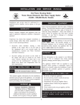
INSTALLATION AND SERVICE MANUAL
Power-Fin® 4:1
HOT WATER HEATING BOILERS
DOMESTIC HOT WATER SUPPLY BOILERS
1,500,000, 1,700,000 and 2,000,000 Btu/hr MODELS
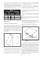
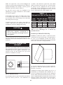
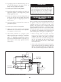
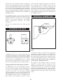
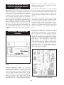
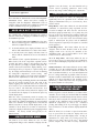
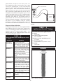
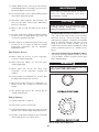
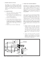
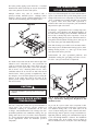
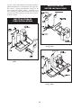
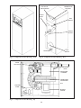
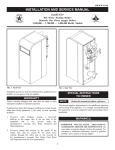
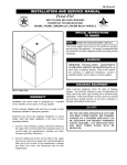
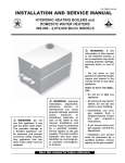
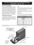
FIG. 1 Front View 1,500,000 - 2,000,000 Btu/hr Models
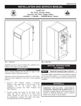
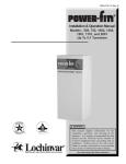
FIG. 2 Rear View 1,500,000 - 2,000,000 Btu/hr Models
WARRANTY
SPECIAL INSTRUCTIONS
TO OWNER
Installation and service must be performed by a qualified
service installer, service agency or the gas supplier.
Factory warranty (shipped with unit) does not apply to
units improperly installed or improperly operated.
Experience has shown that improper installation or system
design, rather than faulty equipment, is the cause of most
operating problems.
1. Excessive water hardness causing a lime/scale build-up
in the copper tube is not the fault of the equipment and
is not covered under the manufacturer's warranty (See
Water Treatment and Water Chemistry).
2. Excessive pitting and erosion on the inside of the
copper tube may be caused by too much water velocity
through the tubes and is not covered by the
manufacturer's warranty (See Boiler Flow Rates and
Temperature Rise for flow requirements).
NOTE:
Retain this manual for future reference.
This manual supplies information for the installation,
operation and servicing of the appliance. It is strongly
recommended that this manual be reviewed completely
before proceeding with an installation.
WARNING:
IMPROPER INSTALLATION, ADJUSTMENT,
ALTERATION, SERVICE OR MAINTENANCE
can cause injury or property damage. Refer to this
manual. For assistance or additional information,
consult a qualified installer, service agency or the gas
supplier.
CHECKING EQUIPMENT
Upon receiving equipment, check for signs of shipping
damage. Pay particular attention to parts accompanying
the boiler, which may show signs of being hit or otherwise
being mishandled. Verify total number of pieces shown on
packing slip with those actually received. In case there is
damage or a shortage, immediately notify carrier.
DO NOT:
DO NOT USE THIS APPLIANCE IF ANY
PART HAS BEEN UNDER WATER. THE
POSSIBLE DAMAGE TO A FLOODED
APPLIANCE CAN BE EXTENSIVE AND
PRESENT NUMEROUS SAFETY HAZARDS.
ANY APPLIANCE THAT HAS BEEN UNDER
WATER MUST BE REPLACED.
WARNING:
If the information in this manual is not followed
exactly, a fire or explosion may result causing
property damage, personal injury or loss of life.
This appliance MUST NOT be installed in any
location where gasoline or flammable vapors
are likely to be present, unless the installation is
such to eliminate the probable ignition of
gasoline or flammable vapors.
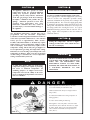
WHAT TO DO IF YOU SMELL GAS
•Do not try to light any appliance.
•Do not touch any electric switch; do not use
any phone in your building.
•Immediately call your gas supplier from a
neighbors phone. Follow the gas supplier's
instructions.
•If you cannot reach your gas supplier, call
the fire department.
Installation and service must be
performed by a qualified installer,
service agency or the gas supplier.
2
CONTENTS
Warranty . . . . . . . . . . . . . . . . . . . . . . . . . . . . . . . . . . . . .1
Safety Warnings . . . . . . . . . . . . . . . . . . . . . . . . . . . . . . .2
Codes
. . . . . . . . . . . . . . . . . . . . . . . . . . . . . . . . . . . . .4
Installation Requirements
Location . . . . . . . . . . . . . . . . . . . . . . . . . . . . . . . . . . . . .4
Clearances . . . . . . . . . . . . . . . . . . . . . . . . . . . . . . . . . . . .5
Combustion/Ventilation Air Requirements . . . . . . . . . . .5
Construction Air Filter . . . . . . . . . . . . . . . . . . . . . . . . . .8
Venting Options
Category IV Venting . . . . . . . . . . . . . . . . . . . . . . . . . . . .9
Flue Pipe Sizes . . . . . . . . . . . . . . . . . . . . . . . . .9
Flue Pipe Materials . . . . . . . . . . . . . . . . . . . . .10
Vent Length Requirements . . . . . . . . . . . . . . .10
Masonry Chimneys . . . . . . . . . . . . . . . . . . . . .11
Vertical Terminations . . . . . . . . . . . . . . . . . . .12
Horizontal Terminations . . . . . . . . . . . . . . . . .12
Direct Vent Systems . . . . . . . . . . . . . . . . . . . . . . . . . . .14
Vertical Direct Vent . . . . . . . . . . . . . . . . . . . . . . . .15
Air Inlet Pipe Materials . . . . . . . . . . . . . . . . .15
Combined Air Inlets . . . . . . . . . . . . . . . . . . . .15
Air Inlet Pipe Length Requirements . . . . . . .16
Location Requirements . . . . . . . . . . . . . . . . . .16
Multiple Vertical Direct Vent Installations . . .17
Horizontal Direct Vent . . . . . . . . . . . . . . . . . . . . . .17
Air Inlet Pipe Materials . . . . . . . . . . . . . . . . .17
Air Inlet Pipe Length Requirements . . . . . . .17
Location Requirements . . . . . . . . . . . . . . . . . .18
Multiple Horizontal Direct Vent Installations 18
DirectAire Vent Systems . . . . . . . . . . . . . . . . . . . . .19
Materials . . . . . . . . . . . . . . . . . . . . . . . . . . . . .19
Vertical Flue - Sidewall Air . . . . . . . . . . . . . .19
Sidewall Flue - Rooftop Air . . . . . . . . . . . . . .20
Sidewall Flue - Sidewall Air . . . . . . . . . . . . .21
Gas Supply
Gas Supply Pressures . . . . . . . . . . . . . . . . . . .23
Manifold Pressure . . . . . . . . . . . . . . . . . . . . .23
Gas Pipe Sizing . . . . . . . . . . . . . . . . . . . . . . .24
Supply Pressure Measurement . . . . . . . . . . . .25
Water Connections . . . . . . . . . . . . . . . . . . . . . . . . . . . .27
Heat Exchanger . . . . . . . . . . . . . . . . . . . . . . . . . . . . . . .28
Minimum Water Temperatures . . . . . . . . . . . . . . . . .28
Flow Switch . . . . . . . . . . . . . . . . . . . . . . . . . . . . . . . . .28
Low Water Cut-Off . . . . . . . . . . . . . . . . . . . . . . . . . . . .28
Relief Valve . . . . . . . . . . . . . . . . . . . . . . . . . . . . . . . . . .29
Gas Train . . . . . . . . . . . . . . . . . . . . . . . . . . . . . . . . . . . .29
Ratio Gas Valve . . . . . . . . . . . . . . . . . . . . . . .29
Diaphragm Gas Valve . . . . . . . . . . . . . . . . . .30
Electrical Requirements . . . . . . . . . . . . . . . . . . . . . . . .30
Jacket
. . . . . . . . . . . . . . . . . . . . . . . . . . . . . . . . . . . .31
Components and Controls
Component Location Drawings . . . . . . . . . . .32
Variable Frequency Drive . . . . . . . . . . . . . . . .33
Low Air Pressure Switch . . . . . . . . . . . . . . . .33
Gas Pressure Switches . . . . . . . . . . . . . . . . . .34
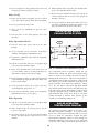
Electronic Temperature Controller . . . . . . . . .34
Location . . . . . . . . . . . . . . . . . .34
Diagnostic Information Center.. 35
Changeable Data Points . . . . . .35
Operation Status LED's . . . . . . .36
Fault Status LED's . . . . . . . . . .36
Temperature Adjustment . . . . . .37
Outdoor Reset Function . . . . . .37
Lockout Procedure . . . . . . . . . .38
Limited Access Features . . . . . .38
Error Displays . . . . . . . . . . . . . .39
Temperature Limit Control . . . . . . . . . . . . . . .39
Condensate Trap Installation . . . . . . . . . . . . .40
Hot Surface Ignition Control . . . . . . . . . . . . .41
Igniter . . . . . . . . . . . . . . . . . . . .41
Diagnostic Status . . . . . . . . . . .42
Ignition and Control Timings . . . . . . . . . . . . .42
Burner Assembly . . . . . . . . . . . . . . . . . . . . . .42
Combustion Air Blower . . . . . . . . . . . . . . . . .43
Cleaning Air Inlet Filter . . . . . . . . . . . . . . . . .43
Lighting Instructions . . . . . . . . . . . . . . . . . . . . . . . . .44
Sequence of Operation . . . . . . . . . . . . . . . . . . . . . . . .45
Maintenance
. . . . . . . . . . . . . . . . . . . . . . . . . .46
Vent System . . . . . . . . . . . . . . . . . . . . . . . . . .46
Flame Patterns . . . . . . . . . . . . . . . . . . . . . . . .47
Cleaning Flue Gas Passageways . . . . . . . . . .47
Burner Cleaning . . . . . . . . . . . . . . . . . . . . . . .47
Changing the HSI . . . . . . . . . . . . . . . . . . . . . .48
Heat Exchanger Inspection . . . . . . . . . . . . . . .49
Lubrication . . . . . . . . . . . . . . . . . . . . . . . . . .50
Control Circuit Voltage . . . . . . . . . . . . . . . . . .50
Condensate Trap . . . . . . . . . . . . . . . . . . . . . . .50
Combustion Blower Measurements . . . . . . . .50
Freeze Protection . . . . . . . . . . . . . . . . . . . . . .51
Heating Boiler
Typical Piping . . . . . . . . . . . . . . . . . . . . . . . . .52
Boiler Pump Operation . . . . . . . . . . . . . . . . . .53
Intermittent Pump . . . . . . . . . . . . . . . . . . . . . .53
Primary/Secondary Piping . . . . . . . . . . . . . . .53
Minimum Water Temperatures . . . . . . . . . . . .54
Low Water Temperature Bypass . . . . . . . . . . .54
Three Way Valves . . . . . . . . . . . . . . . . . . . . . .55
High Flow Bypass . . . . . . . . . . . . . . . . . . . . .56
Boiler Flow Rates . . . . . . . . . . . . . . . . . . . . . .56
Placing the Boiler in Operation . . . . . . . . . . .57
Boiler Temperature Control . . . . . . . . . . . . . .58
Water Heater/Domestic Hot Water Supply Boiler
Typical Piping . . . . . . . . . . . . . . . . . . . . . . . . .60
Maximum Flow Rate . . . . . . . . . . . . . . . . . . .60
Water Velocity Control . . . . . . . . . . . . . . . . . .60
Temperature Rise . . . . . . . . . . . . . . . . . . . . . .61
Water Chemistry . . . . . . . . . . . . . . . . . . . . . . .61
Piping Requirements . . . . . . . . . . . . . . . . . . .62
Pump Operation . . . . . . . . . . . . . . . . . . . . . . .63
Temperature Adjustment . . . . . . . . . . . . . . . . .64
Minimum Water Temperatures . . . . . . . . . . . .64
Risk of Scald Warnings . . . . . . . . . . . . . . . . .65
Temperature Limit Control . . . . . . . . . . . . . . .66
Relief Valve . . . . . . . . . . . . . . . . . . . . . . . . . .66
Thermal Expansion . . . . . . . . . . . . . . . . . . . . .66
3
of such requirements, the installation shall conform to the
latest edition of the National Fuel Gas Code, ANSI Z223.1.
Where required by the authority having jurisdiction, the
installation must conform to American Society of
Mechanical Engineers Safety Code for Controls and Safety
Devices for Automatically Fired Boilers, ASME CSD-1.
All boilers conform to the latest edition of the ASME
Boiler and Pressure Vessel Code, Section IV. Where
required by the authority having jurisdiction, the
installation must comply with the Canadian Gas
Association Code, CAN/CGA-B149.1 and/or B149.2
and/or local codes. This appliance meets the safe lighting
performance criteria with the gas manifold and control
assembly provided, as specified in the ANSI standards for
gas-fired units, ANSI Z21.13.
OWNER WARNING:
The information contained in this manual is intended
for use by qualified professional installers, service
technicians or gas suppliers. Consult your local expert
for proper installation or service procedures.
IMPORTANT:
Consult and follow local Building and Fire
Regulations and other Safety Codes that apply to
this installation. Consult local gas utility company
to authorize and inspect all gas and flue
connections.
INSTALLATION PROCEDURE
LOCATION OF UNIT
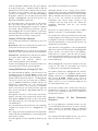
A gas appliance that draws combustion air from the
equipment room where it is installed must have a supply of
fresh air circulating around it during burner operation for
proper gas combustion and proper venting.
1. Locate the appliance so that if water connections
should leak, water damage will not occur. When such
locations cannot be avoided, it is recommended that a
suitable drain pan, adequately drained, be installed
under the unit. The pan must not restrict combustion
airflow. Under no circumstances is the manufacturer to
be held responsible for water damage in connection
with this unit, or any of its components.
WARNING:
Should overheating occur or the gas supply fail
to shut off, DO NOT turn off or disconnect the
electrical supply to the pump. Instead, shut off
the gas supply at a location external to the
appliance.
2. The appliance must be installed so that the ignition
system components are protected from water (dripping,
spraying, etc.) during appliance operation and service
(circulator replacement, control replacement, etc.).
WARNING:
To minimize the possibility of serious personal
injury, fire or damage to your appliance, never
violate the following safety rules.
3. Appliances located in a residential garage and in
adjacent spaces that open to the garage and are not part
of the living space of a dwelling unit must be installed
so that all burners and burner ignition devices have a
minimum clearance of not less than 18" (46cm) above
the floor. The appliance must be located or protected so
that it is not subject to physical damage by a moving
vehicle.
1. Boilers and water heaters are heat producing
appliances. To avoid damage or injury, do not store
materials against the appliance or the vent-air intake
system. Use proper care to avoid unnecessary
contact (especially children) with the appliance and
vent-air intake components.
4. DO NOT install this appliance in any location where
gasoline or flammable vapors are likely to be present.
2. Never cover your appliance, lean anything against it,
store trash or debris near it, stand on it or in any way
block the flow of fresh air to your appliance.
5. The appliance must be installed on a level floor.
Combustible floor locations may be used. Maintain
required clearances from combustible surfaces.
3. UNDER NO CIRCUMSTANCES must flammable
materials such as gasoline or paint thinner be used or
stored in the vicinity of this appliance, vent-air intake
system or any location from which fumes could reach
the appliance or vent-air intake system.
6. The appliance must not be installed on carpet.
7. The appliance must be installed indoors where it is
protected from exposure to wind, rain and weather.
CODES
8. This appliance may condense the products of
combustion when operating at water temperatures
below 140°F (60°C). Ensure that the appliance is
located near an acceptable drain where condensate that
may form in the venting system may be properly
collected and disposed.
The equipment shall be installed in accordance with those
installation regulations in force in the local area where the
installation is to be made. These shall be carefully
followed in all cases. Authorities having jurisdiction shall
be consulted before installations are made. In the absence
4
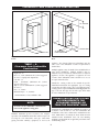
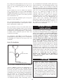
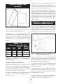
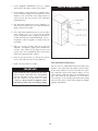
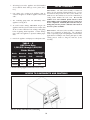
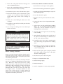
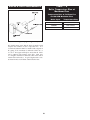
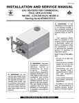
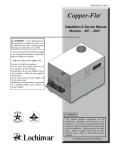
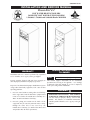
CLEARANCES FROM COMBUSTIBLE CONSTRUCTION
24" TOP MIN.
0" RIGHT SIDE
24" REAR MIN.
FROM PIPING
0" LEFT SIDE
24" FRONT MIN.
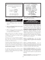
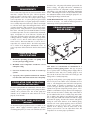
FIG. 3 Clearances from Combustible Construction Front
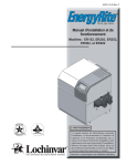
FIG. 4 Clearances from Combustible Construction Rear
appliance. The clearance labels on each appliance note the
same service and combustible clearance requirements as
shown above.
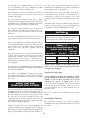
TABLE — A
Clearances from Combustible
Construction:
Multiple appliances may be installed in a modular boiler or
water heater installation. Multiple appliances may be
installed side by side with no clearance between adjacent
appliances because this appliance is approved for zero
clearance from combustible surfaces and no service access
is required from the sides.
Right Side - 0"
Rear - 6" (15cm) (Minimum 24" (0.61m) suggested
for service to pump and components)
Left Side - 0"
Front - ALCOVE* (Minimum 24" (0.61m)
suggested for service)
Top - 6" (15cm) (Minimum 24" (0.61m) suggested
for service)
Flue - 2" (51mm)
Hot Water Pipes - 1" (25.4mm)
Consult the venting section of the manual for specific
installation instructions for appropriate type of venting
system that you will be using. Direct Vent and DirectAire
venting systems require installation with Category IV flue
pipe, sealed air inlet pipe and air inlet caps, which must
meet the manufacturer's specifications.
*An ALCOVE is a closet without a door.
COMBUSTION AND VENTILATION
AIR REQUIREMENTS FOR
APPLIANCES DRAWING AIR
FROM THE EQUIPMENT ROOM
NOTE:
Clearances from combustible construction are
noted on the appliance rating plate.
Provisions for combustion and ventilation air must be in
accordance with Section 5.3, Air for Combustion and
Ventilation, of the latest edition of the National Fuel Gas
Code, ANSI Z223.1, in Canada, the latest edition of CGA
Standard B149 Installation Code for Gas Burning
Appliances and Equipment, or applicable provisions of the
local building codes.
Maintain minimum specified clearances for adequate
operation. All installations must allow sufficient space for
servicing the vent connections, water pipe connections,
piping and other auxiliary equipment, as well as the
5
The equipment room MUST be provided with properly
sized openings to assure adequate combustion air and
proper ventilation when the unit is installed with a basic
Category IV venting system.
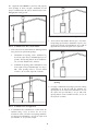
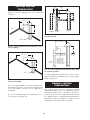
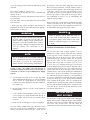
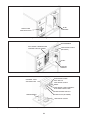
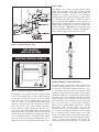
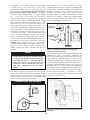
FIG. 7 Combustion Air from Interior Space
3. If air is taken from another interior space, each of the
two openings specified above should have a net free area
of one square inch for each 1000 Btu (22 cm2 per kW) of
input, but not less than 100 square inches (645 cm2).
FIG. 5 Combustion Air Direct from Outside
1. If air is taken directly from outside the building with no
duct, provide two permanent openings:
a.
Combustion air opening, with a minimum free
area of one square inch per 4000 Btu input (5.5 cm2
per kW). This opening must be located within 12"
(30 cm) of the bottom of the enclosure.
b.
Ventilation air opening, with a minimum free area
of one square inch per 4000 Btu input (5.5 cm2 per
kW). This opening must be located within
12 inches (30 cm) of the top of the enclosure.
FIG. 8 Combustion Air from Outside - Single
Opening
4. If a single combustion air opening is provided to bring
combustion air in directly from the outdoors, the
opening must be sized based on a minimum free area of
one square inch per 3000 Btu (7 cm2 per kW). This
opening must be located within 12 inches (30 cm) of
the top of the enclosure.
FIG. 6 Combustion Air Through Ducts
2. If combustion and ventilation air is taken from the
outdoors using a duct to deliver the air to the
mechanical room, each of the two openings should be
sized based on a minimum free area of one square inch
per 2000 Btu (11 cm2 per kW) of input.
6
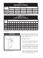
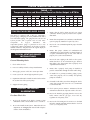
TABLE — B
Minimum Recommended Combustion Air Supply to Equipment Room
COMBUSTION AIR SOURCE
Boiler
Input
1,500,000
1,700,000
2,000,000
Outside Air*
1 - Opening
Outside Air*
2 - Openings
375 in2 (2,419 cm2)
425 in2 (2,742 cm2)
500 in2 (3,226 cm2)
500 in2 (3,226 cm2)
567 in2 (3,658 cm2)
667 in2 (4,303 cm2)
Inside Air
2 - Openings
1500 in2 (9,677 cm2)
1700 in2 (10,968 cm2)
2000 in2 (12,903 cm2)
*Outside air openings shall directly communicate with the outdoors. When combustion air is drawn from the outside
through a duct, the net free area of each of the two openings must have twice (2 times) the free area required for Outside
Air/2 Openings. The above requirements are for the boiler only; additional gas fired appliances in the equipment room
will require an increase in the net free area to supply adequate combustion air for all appliances. Combustion air
requirements are based on the latest edition of the National Fuel Gas Code, ANSI Z223.1; in Canada refer to the latest
edition of CGA Standard CAN B149.1 or .2. Check all local code requirements for combustion air.
All dimensions based on net free area in square inches.
Metal louvers or screens reduce the free area of a
combustion air opening a minimum of approximately 25%.
Check with louver manufacturers for exact net free area of
louvers. Where two openings are provided, one must be
within 12 inches (30 cm) of the ceiling and one must be
within 12 inches (30 cm) of the floor of the mechanical
room. Each opening must have net free area as specified in
the chart above. Single openings shall commence within
12 inches (30 cm) of the ceiling.
The combustion air supply must be completely free of any
flammable vapors that may ignite or chemical fumes which
may be corrosive to the appliance. Common corrosive
chemical fumes which must be avoided are fluorocarbons
and other halogenated compounds, most commonly present
as refrigerants or solvents, such as Freon, trichlorethylene,
perchlorethylene, chlorine, etc. These chemicals, when
burned, form acids which quickly attack the heat exchanger
finned tubes, headers, flue collectors, and the vent system.
The result is improper combustion and a non-warrantable,
premature appliance failure.
CAUTION
EXHAUST FANS: Any fan or equipment which exhausts
air from the equipment room may deplete the combustion
air supply and/or cause a down draft in the venting system.
Spillage of flue products from the venting system into an
occupied living space can cause a very hazardous condition
that must be immediately corrected. If a fan is used to
supply combustion air to the equipment room, the installer
must make sure that it does not cause drafts that could lead
to nuisance operational problems with the appliance.
Under no circumstances should the mechanical
room ever be under a negative pressure. Particular
care should be taken where exhaust fans, attic fans,
clothes dryers, compressors, air handling units,
etc., may take away air from the unit.
7
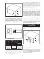
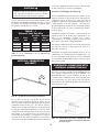
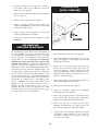
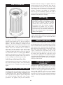
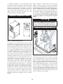
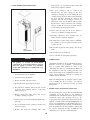
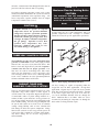
CONSTRUCTION AIR FILTER
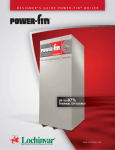
FIG. 9 Construction Air Filter
A construction air filter is provided with the appliance as
shipped. An air filter is provided for installation on the
combustion air inlet located at the rear of the appliance.
This filter is For Temporary Use Only on an appliance that
must be operated for temporary heat or hot water when a
building is under construction. The filter will provide a
temporary means to remove airborne dust, dirt and
particulate matter generated by construction. The filter
prevents air borne particulate contaminants from being
drawn into the burner with the combustion air. The filter can
be cleaned routinely during construction if necessary.
Remove the filter to clean. Wash the filter with water. A
flow of water from the inside to the outside should remove
most particulate mater. Allow the filter to dry before
reinstalling. Unfiltered combustion air from a construction
site can contain contaminants that will collect in the burner
reducing the firing rate. A burner that becomes clogged with
air borne particulate contaminants must be removed and
cleaned to restore proper operation to the burner. Sustained
operation of an appliance with a clogged burner may result
in nuisance operational problems, bad combustion and
non-warrantable component failures. The combustion air
filter MUST be removed from the appliance's air inlet before
the appliance is placed in normal operation. Once the
construction air filter is removed, ensure that either the
equipment room is supplied with combustion air from
properly sized combustion and ventilation air openings or a
combustion air duct from a Direct Vent or DirectAire system
is connected to the appliance.
TABLE — C
Construction Air Filter Kits
Input Btu/hr
Construction
Air Filter Kit
1,500,000
KIT4000
1,700,000
KIT4001
2,000,000
KIT4002
VENTING
Vent Systems Options
This appliance has three venting system options. They are:
(A) Category IV Venting system with vertical roof top
termination or sidewall termination of the flue and
combustion air supplied from the mechanical room. (B)
Direct Vent with a Category IV flue and a separate
combustion air pipe to the outdoors. The Direct Vent
system terminates both the flue and air inlet in the same
pressure zone. The flue outlet and combustion air intake
may terminate on either the sidewall or with a rooftop
termination. (C) DirectAire with a Category IV flue and
a separate combustion air pipe to the outdoors. The
DirectAire vent system terminates the flue and the
combustion air inlet pipe in different pressure zones. The
DirectAire vent system may terminate the flue on the roof
top and combustion air intake on the sidewall, the flue on
the sidewall and combustion air from the rooftop or the flue
on the sidewall and combustion air from a different
The optional Direct Vent and DirectAire venting systems
have specific requirements for a special combustion air duct
from the outside that is directly connected to the appliance.
See the requirements for this combustion air duct in the
venting section for each specialized vent system.
8
sidewall. All appliances are shipped from the factory
equipped for Category IV venting. The optional Direct
Vent and DirectAire venting systems will require the
installation of specific vent kits and venting materials. The
following is a detailed explanation of the installation
requirements for each venting system, components used
and part numbers of vent kits for each model.
Category IV Venting
A CATEGORY IV POSITIVE
PRESSURE VENTING SYSTEM
General
Vent installations for connection to gas vents or chimneys
must be in accordance with Part 7, "Venting of
Equipment," of the latest edition of the National Fuel Gas
Code, ANSI Z223.1, in Canada, the latest edition of CGA
Standard B149 Installation Codes for Gas Burning
Appliances and Equipment or applicable provisions of the
local building codes.
Adequate combustion and ventilation air must be supplied
to the equipment room in accordance with the latest edition
of the National Fuel Gas Code, ANSI Z223.1, in Canada,
the latest edition of CGA Standard B149 Installation Codes
for Gas Burning Appliances and Equipment, or applicable
provisions of the local building codes.
FIG. 10
Basic Category IV Venting - Vertical
Termination with Combustion Air Louvers
FIG. 11
Basic Category IV Venting - Horizontal
Termination with Combustion Air Louvers
The distance of the vent terminal from adjacent buildings,
windows that open and building openings MUST comply
with the latest edition of the National Fuel Gas Code, ANSI
Z223.1, in Canada, the latest edition of CGA Standard
B149 Installation Codes for Gas Burning Appliances and
Equipment.
Vent connection is made directly to flue outlet opening on
the back of the unit. The connection from the appliance
vent to the stack must be made as direct as possible.
IMPORTANT
Examine the venting system at least once a year.
Check all joints and vent pipe connections for tightness.
Also check for corrosion or deterioration. Immediately
correct any problems observed in the venting system.
A Category IV venting system for the flue products is
required on all models of this appliance. A Category IV
venting system operates with a positive pressure in the
vent. This positive pressure is generated by the internal
combustion air blower which operates the combustion
process and also exhausts the flue products from the
building. The Category IV flue from this appliance can
NOT be combined with the vent from any other appliance.
The Category IV flues from multiple appliances can NOT
be combined into a common vent. The Category IV flue
from this appliance must be a dedicated stack, there is one
exception however. The flues from multiple Power-Fin
appliances may only be combined when using an
engineered vent system incorporating an induced draft fan
to ensure that flue products will be properly exhausted
from the building at all times. Failure to use a properly
sized induced draft fan on a combined vent installation may
TABLE — D
The Category IV Flue
Pipe Sizes Are:
Input Btu/hr
Flue Size
1,500,000
8”
1,700,000
8”
10”
2,000,000
9
result in a hazardous condition where flue gases spill into
an occupied living space. Consult the induced draft fan
manufacturer to size the induced draft fan and to determine
the diameter of the common vent pipe required for a
combined vent installation. The flue from this Category
IV appliance must have all vent joints and seams sealed
gas-tight. A Category IV vent system has specific vent
material and installation requirements.
The flue products in the vent system may be cooled below
their dew point and form condensate in the flue. The
materials used for a Category IV vent must be resistant to
any corrosive damage from flue gas condensate. The flue
from a Category IV vent system must have a condensate
drain with provisions to properly collect and dispose of any
condensate that may occur in the venting system.
Category IV Flue Pipe Materials
Select venting material from the following specified vent
materials:
Heat-Fab Inc. Saf-T CI Vent with AL29-4C stainless steel
(Call 1-800-772-0739 for nearest distributor)
Protech Systems Inc. Fas N Seal Vent with AL29-4C
stainless steel (Call 1-800-766-3473 for nearest distributor)
Metal-Fab Inc. Corr/Guard Vent with AL29-4C stainless
steel (Call 1-800-835-2830 for nearest distributor)
Z-Flex Z-Vent with AL29-4C stainless
(Call 1-800-654-5600 for nearest distributor)
steel
Or other listed Category IV vent systems suitable for a
condensing, positive pressure gas fired appliance.
There shall be no reductions in vent diameter.
Horizontal portions of the venting system shall be
supported to prevent sagging. Horizontal runs should slope
upwards not less than 1/4 inch per foot (21 mm/m) from the
drain tee installed in the flue to the vertical portion of the
flue or to the vent terminal on sidewall venting
installations. This ensures proper removal of any
condensate that may form in the flue. Follow the
installation instructions from the vent material
manufacturer.
Do not use an existing chimney as a raceway if another
appliance or fireplace is vented through the chimney.
The weight of the venting system must not rest on the unit.
Adequate support of the venting system must be provided
in compliance with local codes and other applicable codes.
All connections should be secured and sealed per the vent
manufacturers specifications.
Vent connectors serving appliances vented by natural draft
shall not be connected to any portion of the Category IV
positive pressure vent system used by this appliance.
Connection of a negative draft flue into the positive
pressure stack from this appliance may cause flue products
to be discharged into an occupied living space causing
serious health injury.
When a Category IV vent system is disconnected for any
reason, the flue must be reassembled and resealed
according to the vent manufacturer's instructions.
Venting Guidelines for a Category IV Vent
The connection from the appliance vent to the stack or vent
termination outside the building MUST be made with
listed Category IV vent system and must be direct as
possible with no reduction in diameter. The Category IV
vent and accessories, such as firestop spacers, thimbles,
caps, etc., MUST be installed in accordance with the vent
manufacturers instructions. The vent connector and
firestop must provide correct spacing to combustible
surfaces and seal to the vent connector on the upper and
lower sides of each floor or ceiling through which the vent
connector passes.
Each appliance must have a dedicated flue with no other
appliance interconnected to any part of the dedicated flue.
Each appliance MUST also connect to the dedicated flue
stack using a properly sealed vent adapter provided by the
vent manufacturer.
Any vent materials specified must be listed by a nationally
recognized test agency for use as a Category IV vent
material.
The venting system must be planned so as to avoid possible
contact with concealed plumbing or electrical wiring inside
walls, floors or ceilings.
Locate the appliance as close as possible to chimney or gas
vent.
The installed length of the Category IV flue from the
appliance to the point of termination, outside of the
building, must not exceed a maximum of 50 equivalent
feet (15.2 m) in length. Subtract 5 feet (1.5 m) of
equivalent length for each 90° elbow installed in the vent.
Subtract 2-1/2 feet (0.7 m) of equivalent length for each
45° elbow installed in the vent.
The flue may terminate either vertically at the roof top or
horizontally on a sidewall. See the information about the
specific vent termination location for recommended
location and clearances.
General Category
Clearances
IV
Vent
Termination
The vent cap should have a minimum clearance of 4 feet
(1.2 m) horizontally from and in no case above or below,
unless a 4 foot (1.2 m) horizontal distance is maintained
from electric meters, gas meters, regulators and relief
equipment.
The venting system shall terminate at least 3 feet (0.9 m)
above any forced air inlet within 10 feet (3.05 m).
10
The venting system shall terminate at least 4 feet (1.2 m)
below, 4 feet (1.2 m) horizontally from, or 1 foot (30 cm)
above any door, window or gravity air inlet into any
building.
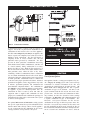
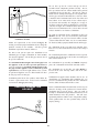
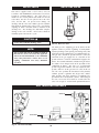
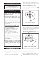
the vent manufacturer's instructions, shall be provided as a
drain line from the tee. The drain tubing must have a trap
provided by a 4 inches (10.2 cm) diameter circular trap
loop in the drain tubing. Prime the trap loop by pouring a
small quantity of water into the drain hose before assembly
to the vent. Secure the trap loop in position with nylon
wire ties. Use caution not to collapse or restrict the
condensate drain line with the nylon wire ties. The
condensate drain must be routed to the condensate
neutralization system or a suitable drain for disposal of
condensate that may occur in the Category IV vent
system. Refer to the condensate drain installation
instructions as supplied by the manufacturer of the vent
material. Ensure that the drain from the condensate tee is
not exposed to freezing temperatures. See “Freeze
Protection” for more information.
Do not terminate the vent in a window well, stairwell,
alcove, courtyard or other recessed area. The vent can not
terminate below grade. The bottom of the vent terminal
shall be located at least 12 inches (30 cm) above grade and
above normal snow levels.
To avoid a blocked flue condition, keep the vent cap clear
of snow, ice, leaves, debris, etc.
Flue gases from this appliance may contain large amounts
of water vapor that will form a white plume in winter.
Plume could obstruct a window view.
MASONRY CHIMNEY
INSTALLATIONS
Flue gas condensate can freeze on exterior surfaces or on
the vent cap. Frozen condensate on the vent cap can result
in a blocked flue condition. Flue gas condensate can cause
discoloration of exterior building surfaces. Adjacent brick
or masonry surfaces should be protected with a rust
resistant sheet metal plate.
A standard masonry chimney must NOT be used to vent
the products of combustion from the flue of a Category IV,
positive pressure appliance. If a masonry chimney is to
be used, the chimney MUST use a sealed, metallic,
corrosion resistant liner system to vent flue products
from this high efficiency appliance. Sealed, metallic,
corrosion resistant liner systems (single wall, doublewall, or flexible or rigid metallic liners) must be rated
for use with a high efficiency, Category IV, positive
pressure vent system. Corrosion resistant chimney liner
systems are typically made from a high grade of corrosion
resistant stainless steel such as AL29-4C. The corrosion
resistant liner must be properly sized and fully sealed
throughout the entire length if the flue is contained within
the masonry chimney. Both the top and the bottom of the
masonry chimney must be capped and sealed to provide a
dead air space around the sealed corrosion resistant
metallic liner. Consult with local code officials to
determine code requirements or the advisability of
using a masonry chimney with a sealed corrosion
resistant liner system.
The manufacturer shall NOT be held liable for any
personal injury or property damage due to ice formation or
the dislodging of ice from the vent system or the vent
termination.
Drain Tee Installation
WIRE TIE
4" Ø
CIRCULAR TRAP
CAUTION:
Venting of a high efficiency Category IV
appliance into a masonry chimney without a sealed
stainless steel liner can result in operational and
safety problems. Any breaks, leaks or damage to
the masonry flue/tile will allow spillage of the
positive pressure flue products from the chimney.
These flue products can easily escape into an
occupied living space causing a health hazard. If
there is any doubt about the condition of a masonry
chimney, or its acceptability for use after insertion
of a corrosion resistant liner system, consult with
local code officials.
TO SUITABLE DRAIN
FIG. 12 Drain Tee Installed In Category IV Venting
A drain tee MUST be installed in the Category IV vent
pipe to collect and dispose of any condensate that may
occur in the vent system. The drain tee should be installed
at the point where the flue turns vertical for a roof top
termination or as one of the first fitting in a horizontal flue
that will terminate on a sidewall. Ensure that horizontal
portions of the vent are properly sloped to allow
condensate to be evacuated at the drain tee. See the typical
vent installation drawings. Plastic drain tubing, sized per
11
VERTICAL VENTING
TERMINATIONS
10' OR LESS
Follow all General Category IV Vent Termination
Clearances.
2' MIN
2' MIN
3' MIN
10' OR LESS
2' MIN
3' MIN
RIDGE
CHIMNEY WALL OR
CHIMNEY
PARAPET
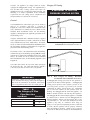
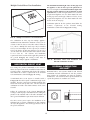
FIG. 15 Vent Termination from Flat Roof 10' or Less
from Parapet Wall
CHIMNEY
10' OR MORE
FIG. 13 Vent Termination from Peaked Roof - 10' or
Less From Ridge
3' MIN
MORE THAN 10'
10'
RIDGE
2' MIN
WALL OR
PARAPET
3' MIN
NOTE: NO HEIGHT
ABOVE PARAPET
REQUIRED WHEN
DISTANCE FOR
WALLS OR PARAPETS
IS MORE THAN 10'>
CHIMNEY
FIG. 16 Vent Termination from Flat Roof More Than
10' from Parapet Wall
CHIMNEY
FIG. 14 Vent Termination from Peaked Roof More
Than 10' From Ridge
The vent terminal should be vertical and exhaust outside
the building at least 2 feet (0.61 m) above the highest point
of the roof within a 10 foot (3.05 m) radius of the
termination.
The vertical termination must be a minimum of 3 feet
(0.91 m) above the point of exit.
A vertical termination less than 10 feet (3.05 m) from a
parapet wall must be a minimum of 2 feet (0.61 m) higher
than the parapet wall.
SIDEWALL VENTING
TERMINATIONS
This venting system uses the appliance's internal
combustion air blower to force the flue products out of a
horizontally-terminated flue. This blower generates a
positive pressure in the flue. Combustion air is drawn from
the equipment room (see Combustion and Ventilation Air
Requirements) unless the appliance is equipped with an
optional Direct Vent or DirectAire vent system.
12
The opening through the wall for installation of the
sidewall vent cap must provide an air space clearance of 2
inches (5.1 cm) around the flue pipe. The diameter of the
opening for installation of the sidewall cap will be 4 inches
(10.2 cm) larger (minimum) than the nominal diameter of
the installed vent pipe to the sidewall cap.
The sidewall cap is installed from the outside and mounted
to the wall with four screws or wall anchors. Seal under the
screw heads with caulking. Install the screen assembly
using the stainless steel screws provided in the kit. Install
the Category IV vent pipe from the appliance to the vent
cap. The installed vent pipe must protrude at least 2 inches
(5.1 cm) into the screen area beyond the thimble portion of
the sidewall cap assembly. See detailed instructions
packed with the sidewall vent kit.
FIG. 17 Sidewall Venting Installation
Follow all requirements in the General Category IV
Venting sections for venting flue products to the outdoors.
See the Combustion and Ventilation Air Requirements
section to ensure that adequate combustion and ventilation
air is supplied to the equipment room. All other general
installation requirements must be followed.
The connection from the appliance flue outlet to the
sidewall vent cap MUST be made with listed type
Category IV vent materials and accessories. The installer
must supply suitable vent pipe material. The sidewall vent
cap is available from the appliance manufacturer as a vent
kit.
LOCATION OF A SIDEWALL VENT
TERMINATION
Follow all General Category IV Vent Termination
Clearances.
FIG. 18 Sidewall Vent Cap
3' MIN.
TABLE — E
Sidewall Vent Cap Kits
Input Btu/hr
Flue Size
Sidewall
Vent Cap Kit
1,500,000
8”
SVK3028
1,700,000
8”
SVK3028
2,000,000
10”
SVK3029
4' MIN.
10' MIN.
FIG. 19 Sidewall Venting Installation with Clearances
From Vent Cap
The vent cap shall terminate at least 3 feet (0.91 m) above
any forced air inlet within 10 feet (3.05 m).
The vent shall terminate at least 4 feet (1.22 m) below,
4 feet (1.22 m) horizontally from or 1 foot (0.30 m) above
and 2 feet (0.60 m) horizontally from any door, window or
gravity air inlet to the building.
The sidewall vent cap kit includes the wall penetration
assembly and the discharge screen assembly. All required
Category IV vent pipe and fittings must be purchased
locally. The installed sidewall vent cap assembly may be
painted to match the exterior décor.
13
The sidewall vent termination must be at least 8 feet
(2.4 m) horizontally from any combustion air intake
located above the sidewall termination cap.
The Direct Vent and Intelli-Vent Systems require the
installation of an additional pipe to supply combustion air
from outdoors directly to the appliance.
Do not terminate the vent in a window well, stairwell,
alcove, courtyard or other recessed area. The vent can not
terminate below grade.
In cold climates, the use of type “B” double wall vent pipe
or an insulated single wall pipe for combustion air is
recommended to help prevent moisture in the cool
incoming air from condensing and leaking from the inlet
pipe.
The vent shall not terminate directly above a public
walkway due to the normal formation of water vapor in the
combustion process. Horizontal terminations must not be
located over areas of pedestrian or vehicular traffic.
The vent system shall terminate at least 1 foot (0.30 m)
above grade, above normal snow levels and at least 7 feet
(2.13 m) above grade when located adjacent to public
walkways.
Termination point for the flue products must follow the
clearance requirements in the Vertical or Horizontal Vent
Termination sections of the Category IV Venting.
CAUTION:
The vent terminal shall not be installed closer than 3 feet
(0.91m) from an inside corner of an L-shaped structure.
Appliances that are shut down or will not operate
may experience freezing due to convective airflow
in the air inlet pipe connected to the appliance.
The vent cap should have a minimum clearance of 4 feet
(1.22 m) horizontally from and in no case above or below,
unless a 4-foot (1.22 m) horizontal distance is maintained
from electric meters, gas meters, regulators and relief
equipment.
TABLE — F
Direct Vent and DirectAire Flue
and Air Inlet Pipe Sizes
Flue gas condensate can freeze on exterior walls or on the
vent cap. Frozen condensate on the vent cap can result in
a blocked flue condition. Some discoloration to exterior
building surfaces can be expected. Adjacent brick or
masonry surfaces should be protected with a rust resistant
sheet metal plate.
The sidewall vent system MUST use the sidewall vent cap
kit provided by the appliance manufacturer for installation
on a sidewall termination.
The sidewall vent cap MUST be purchased as a kit from
the appliance manufacturer to ensure proper operation.
Locally purchased or fabricated sidewall vent caps should
not be used
DIRECT VENT AND
DIRECTAIRE VENT SYSTEMS
Direct Vent and DirectAire Vent Systems are installed with
a Category IV flue and a separate combustion air pipe to
the outdoors. The Direct Vent System terminates both the
flue and combustion air inlet in the same pressure zone.
The DirectAire Vent System terminates the flue and
combustion air inlet in different pressure zones. The flue
outlet and combustion air intake may terminate with either
a sidewall or a rooftop termination.
Follow all requirements in the General Category IV
Venting sections for proper installation and of venting of
flue products vertically or horizontally to the outdoors. All
other general installation requirements must be followed.
Air Inlet
Pipe Size
Input Btu/hr
Flue Size
1,500,000
8”
6”
1,700,000
8”
7”*
2,000,000
10”
8”
*Piping from the appliance to the air inlet cap may be
either 7" or 8". An 8" diameter sidewall air inlet cap is
provided in the venting kit.
Length of Air Inlet Pipe
The maximum total length of the sidewall or vertical
rooftop combustion air inlet pipe as installed from the
appliance to the air inlet cap must not exceed 50
equivalent feet (15.2 m) in length. Subtract 5 feet
(1.52 m) of equivalent length for each 90° elbow installed
in the air inlet pipe system. Subtract 2 1/2 feet (0.7 m) of
equivalent length for each 45° elbow installed in the air
inlet pipe system.
Do not exceed limits for the combustion air inlet piping
lengths.
Air Inlet Pipe Materials
The air inlet pipe(s) must be sealed. Choose acceptable
combustion air inlet pipe materials from those specified in
this section.
14
Select air inlet pipe material from the following specified
materials:
material used. The PVC, CPVC, ABS, Dryer Vent or Flex
Duct air inlet pipe should use a silicone sealant to ensure a
proper seal at the appliance connection and the air inlet cap
connection. Dryer vent or flex duct should use a screw
type clamp to seal the vent to the appliance air inlet and the
air inlet cap. Proper sealing of the air inlet pipe ensures
that combustion air will be free of contaminants and
supplied in proper volume.
PVC, CPVC or ABS (6", 7"or 8" I.D.)*
Dryer Vent or Sealed Flexible Duct (not recommended for
roof top air inlet)
Galvanized steel vent pipe with joints and seams sealed as
specified below.
Type "B" double wall vent with joints and seams sealed as
specified below
When a sidewall or vertical roof top combustion air supply
system is disconnected for any reason, the air inlet pipe
must be resealed to ensure that combustion air will be free
of contaminants and supplied in proper volume.
* Plastic pipe may require an adapter (not provided) to
transition between the air inlet connection on the appliance
and the plastic air inlet pipe.
DANGER:
WARNING:
Failure to properly seal all joints and seams as
required in the air inlet piping may result in flue gas
recirculation, spillage of flue products and carbon
monoxide emissions causing severe personal injury
or death.
Using vent or air intake materials other than those
specified, failure to properly seal all seams and
joints or failure to follow vent pipe manufacturer's
instructions can result in personal injury, death or
property damage. Mixing of venting materials will
void the warranty and certification of the
appliance.
Combined Combustion Air Inlet Points
The air inlet pipes from multiple appliances can be
combined to a single common connection if the common
air inlet pipe has a cross sectional area equal to or larger
than the total area of all air inlet pipes connected to the
common air inlet pipe. [Example: two 8" (20.3 cm) air inlet
pipes (50.3 in2 (324.5 cm2) area each) have a total area of
100.6 in2 (645.2 cm2) requires a 12 inches (30.5 cm) (113.1
in2 area) (729.7 cm2) common air inlet pipe.] The air inlet
point for multiple boiler air inlets must be provided with an
exterior opening which has a free area equal to or greater
than the total area of all air inlet pipes connected to the
common air inlet. This exterior opening for combustion air
must connect directly to the outdoors. The total length of
the combined air inlet pipe must not exceed a maximum of
50 (15.2 m) equivalent feet. You must deduct the restriction
in area provided by any screens, grills or louvers installed
in the common air inlet point. These are common on the
sidewall air inlet openings and some rooftop terminations.
Screens, grills or louvers installed in the common air inlet
can reduce the free area of the opening from 25% to 75%
based on the materials used.
NOTE:
The use of double wall vent or insulated material
for the combustion air inlet pipe is recommended in
cold climates to prevent the condensation of
airborne moisture in the incoming combustion air.
Sealing of Type "B" double wall vent material or
galvanized vent pipe material used for air inlet pipe on
a sidewall or vertical roof top Combustion Air Supply
System.
a. Seal all joints and seams of the air inlet pipe using
either Aluminum Foil Duct Tape meeting UL Standard
723 or 181A-P or a high quality UL Listed silicon
sealant such as those manufactured by Dow Corning or
General Electric.
b. Do not install seams of vent pipe on the bottom of
horizontal runs.
VERTICAL DIRECT
VENT SYSTEMS
c. Secure all joints with a minimum of three sheet metal
screws or pop rivets. Apply aluminum foil duct tape or
silicone sealant to all screws or rivets installed in the
vent pipe.
A Vertical Direct Vent System is installed with a Category
IV flue and a separate combustion air pipe to the outdoors.
The Direct Vent system terminates both the flue and air
inlet in the same pressure zone. The flue outlet and
combustion air intake must both terminate on the rooftop.
d. Ensure that the air inlet pipes are properly supported.
The PVC, CPVC or ABS air inlet pipe should be cleaned
and sealed with the pipe manufacturers recommended
solvents and standard commercial pipe cement for the
15
3'
12"
FIG. 20 Vertical Direct Vent Installation with Rooftop
Combustion Air Inlet
Follow all requirements in the General Category IV
Venting sections for proper installation and of venting flue
products vertically to the outdoors. All other general
installation requirements must be followed.
The Direct Vent system requires the installation of an
additional pipe to supply combustion air from outdoors
directly to the appliance. The air inlet pipe must use one of
the specified materials.
The maximum installed length of the air inlet pipe from
the appliance to the air inlet cap is 50 equivalent feet
(15.2 m) in length. The maximum installed length of the
flue pipe from the appliance to the termination cap is 50
equivalent feet (15.2 m) in length. Subtract 5 feet (1.52 m)
of equivalent length for each 90° elbow installed in either
the flue pipe or the air inlet pipe.
Termination point for the flue products must follow the
clearance requirements in the Vertical Vent Termination
sections of the Category IV Venting.
VERTICAL COMBUSTION
AIR INLET
The air inlet cap for the vertical roof top air inlet is
assembled from components purchased locally. The air
inlet cap consist of two 90° elbows installed at the point of
termination for the air inlet pipe. The first 90° elbow is
installed on the rooftop at the highest vertical point of the
air inlet pipe and turned horizontal, the second 90° elbow
is installed on the horizontal outlet of the first elbow and
turned down. A 90° elbow and a 90° street elbow may be
used to make this assembly. If a straight piece of pipe is
used between the two elbows, it should not exceed 6 inches
(152 mm) in length. The termination elbow on the air inlet
must be located a minimum of 12" (0.30 m) above the roof
or above normal levels of snow accumulation.
The point of termination for the combustion air inlet cap
MUST be at least 3 feet (0.91 m) below the point of flue
gas termination (vent cap) if it is located within a 10 foot
(3.05 m) radius of the flue outlet. Use care to ensure that the
90° elbow assembly is properly installed on the air inlet pipe.
The combustion air inlet cap must not be installed closer
than 10 feet (3.05 m) from an inside corner of an L-shaped
structure.
The termination point of the combustion air inlet cap must
be installed at least one foot (0.30 m) above the rooftop and
above normal snow levels.
The combustion air cap assembly used MUST adequately
protect the combustion air inlet from wind and weather.
The combustion air cap and flue gas outlet MUST be
located on the same roof top surface and in the same
pressure zone.
Combustion air supplied from outdoors must be free of
contaminants (See Combustion and Ventilation Air). To
prevent recirculation of flue products in to the combustion
air inlet, follow all instructions in this section.
Incorrect installation and/or location of the air inlet cap can
allow the discharge of flue products to be drawn into the
combustion process on the heater. This can result in
incomplete combustion and potentially hazardous levels of
carbon monoxide in the flue products. This will cause
operational problems with the heater and possible spillage
of flue products that can cause personal injury, death or
property damage.
FIG. 21 Air Inlet Cap for Rooftop Termination
16
Multiple Vertical Direct Vent Installations
The maximum installed length of the air inlet pipe from
the appliance to the air inlet cap is 50 equivalent feet
(15.2 m) in length. The maximum installed length of the
flue pipe from the appliance to the termination cap is 50
equivalent feet (15.2 m) in length. Subtract 5 feet (1.52 m)
of equivalent length for each 90° elbow installed in either
the flue pipe or the air inlet pipe. Subtract 2 1/2 feet (0.7 m)
of equivalent length for each 45° elbow installed in either
the flue or the air inlet pipe.
Termination point for the flue products must follow the
clearance requirements in the Sidewall Venting
Termination sections of the Category IV Venting.
FIG. 22 Multiple Vertical Direct Vent Installations
The combustion air inlet caps for multiple appliance
installations must maintain the minimum 3 foot (0.91 m)
clearance below the closest vertical flue outlet if within 10
feet (3.05 m). Multiple flue outlet caps may be installed
side by side and multiple air inlet caps may be installed
side by side but the air inlet must always be at least 3 feet
(0.91 m) below the closest flue outlet if the outlet is within
10 feet (3.05 m). All clearance and installation
requirements in this section and the applicable portions of
the general Category IV venting section must be
maintained on multiple appliance installations.
FIG. 23
Horizontal Direct Vent Installation with
Sidewall Combustion Air Inlet
HORIZONTAL DIRECT VENT
SIDEWALL COMBUSTION
AIR INLET
For venting flue products horizontally to the outdoors,
follow all requirements in the installation instructions for
sidewall venting. Termination point for the flue products
must follow the clearance requirements in the Sidewall
Vent Termination section of Category IV Venting.
Horizontal Direct Vent systems installed with sidewall
terminations for both combustion air and flue products
must purchase the termination caps from the appliance
manufacturer. The sidewall air inlet cap and sidewall vent
cap for flue products are available as a vent kit.
A Horizontal Direct Vent System is installed with a
Category IV flue and a separate combustion air pipe to the
outdoors. The Direct Vent system terminates both the flue
and air inlet in the same pressure zone. The flue outlet and
combustion air intake must both terminate on the same
sidewall.
Follow all requirements in the General Category IV
Venting sections for proper installation and of venting flue
products to the outdoors with a sidewall termination. All
other general installation requirements must be followed.
The Direct Vent system requires the installation of an
additional pipe to supply combustion air from outdoors
directly to the appliance. The air inlet pipe must use one of
the specified materials.
FIG. 24 Sidewall Vent Cap
17
The part numbers for the required sidewall air inlet cap kit
are listed by unit size. The manufacturer, in accordance
with CSA/CGA requirements, must furnish the sidewall air
inlet cap. Each kit includes the special combustion air inlet
cap for installation on an exterior sidewall. The sidewall
air inlet cap supplied in the kit is sized to provide
combustion air for a single appliance only.
The sidewall combustion air inlet cap MUST NOT be
installed above the sidewall flue outlet if it is located within
a 10 foot (3.05 m) radius of the flue outlet.
TABLE — G
Horizontal Direct Vent Kits
The sidewall combustion air inlet cap must not be installed
closer than 10 feet (3.05 m) from an inside corner of an
L-shaped structure.
Input
Btu/hr
Flue
Cap Air Inlet
Size Cap Size
Sidewall Air
Inlet Flue
Cap Kit
1,500,000
8”
6”
HDK3021
1,700,000
8”
8”*
HDK3022
2,000,000
10”
8”
HDK3023
*Piping from the appliance to the air inlet cap may be
either 7" or 8" connecting to an 8" sidewall cap
provided in the kit.
Location of a Sidewall Air Inlet Cap
Incorrect installation and/or location of the air inlet cap can
allow the discharge of flue products to be drawn into the
combustion process on the heater. This can result in
incomplete combustion and potentially hazardous levels of
carbon monoxide in the flue products. This will cause
operational problems with the heater and possible spillage
of flue products that can cause personal injury, death or
property damage
horizontally and 12 inches (0.30 m) below the point of flue
gas termination (vent cap) if it is located within a 10 foot
(3.05 m) radius of the flue outlet.
The sidewall combustion air cap assembly used MUST
adequately protect the combustion air inlet from wind and
weather.
The sidewall combustion air inlet cap and flue gas outlet
MUST be located on the same sidewall surface and in the
same pressure zone.
Combustion air supplied from outdoors must be free of
contaminants (See Combustion and Ventilation Air). To
prevent recirculation of flue products in to the combustion
air inlet, follow all instructions in this section.
Multiple Horizontal Direct Vent Installations
FLUE OUTLETS
3' HORIZONTALLY
AIR INLET CAP
1' BELOW FLUE
FIG. 26 Multiple Horizontal Direct Vent Caps Installed
on a Sidewall
FIG. 25 Air Inlet Cap for Sidewall Termination
The termination point of the sidewall air inlet must be
installed a minimum of 12 inches (0.30 m) above ground
level and above normal levels of snow accumulation.
The point of termination for the sidewall combustion air
inlet cap MUST be located a minimum of 3 feet (0.91 m)
The combustion air inlet caps for multiple appliance
installations must maintain the same minimum clearance
from the closest vent cap installed within a 10 foot radius
of the point of flue gas termination as specified in single
appliance installations. Multiple flue outlet caps may be
installed side by side and multiple air inlet caps may be
installed side by side but, the minimum clearance of a 3
feet (0.91 m) horizontal radius and 12 inches (0.30 m)
below the closest flue outlet to the air inlet cap must be
maintained. All clearance and installation requirements in
this section and the applicable portions of the general
Category IV venting section must be maintained on
multiple appliance installations.
18
DIRECTAIRE VENT SYSTEMS
VERTICAL DIRECTAIRE WITH
SIDEWALL COMBUSTION AIR
A DirectAire vent system is a Category IV flue installed
with a separate combustion air pipe to the outdoors. The
DirectAire vent system terminates the flue and the
combustion air inlet pipe in different pressure zones. The
DirectAire vent system may terminate the flue and
combustion air in any one of three configurations. These
are: (1) the flue on the roof top and combustion air intake
on the sidewall; (2) the flue on the sidewall and
combustion air from the rooftop; (3) the flue on the
sidewall and the combustion air on a sidewall other than
the sidewall where the flue is located. All appliances are
shipped from the factory equipped for Category IV
venting system. The optional DirectAire vent systems
require the installation of specific venting materials that are
purchased locally. Sidewall termination caps for flue
products and combustion air must be purchased from the
manufacturer. The sidewall caps for combustion air and
flue products are available as vent kits. The following is a
detailed explanation of the installation requirements for
each venting system, components used and part numbers of
vent kits for each model.
FIG. 27 Vertical DirectAire Installation with Sidewall
Combustion Air Inlet
DirectAire vent systems are installed with a Category IV
flue and a separate combustion air pipe to the outdoors.
The Vertical DirectAire vent system terminates the flue at
the rooftop and air inlet at the sidewall. The flue outlet and
combustion air intake terminate in different pressure zones.
Follow all requirements in the General Category IV
Venting sections for proper installation and of venting flue
products to the outdoors with either a rooftop or a sidewall
termination. All other general installation requirements
must be followed.
Follow all requirements in the General Category IV
Venting sections for proper installation and of venting flue
products vertically to the outdoors. All other general
installation requirements must be followed.
The DirectAire vent system requires the installation of an
additional pipe to supply combustion air from outdoors
directly to the appliance. The air inlet pipe must use one of
the specified materials.
The DirectAire vent system requires the installation of an
additional pipe to supply combustion air from outdoors
directly to the appliance.
Combined Air Inlet Points
Termination point for the flue products must follow the
clearance requirements in the Vertical Vent Termination
section of the Category IV Venting.
The air inlet pipes from multiple appliances installed with
a DirectAire vent system can be combined to a single
common connection based on the cross sectional area of
the common pipe as defined in the Direct-Vent basic
information section.
CAUTION:
Maximum Length of a DirectAire Vent System
Appliances that are shut down or will not
operate may experience freezing due to
convective airflow in the air inlet pipe connected
to the appliance.
The maximum installed length of the air inlet pipe from
the appliance to the air inlet cap is 50 equivalent feet
(15.2 m) in length. The maximum installed length of the
flue pipe from the appliance to the termination cap is 50
equivalent feet (15.2 m) in length. Subtract 5 feet (1.52 m)
of equivalent length for each 90° elbow installed in either
the flue pipe or the air inlet pipe. Subtract 2 1/2 feet (0.7 m)
of equivalent length for each 45° elbow installed in either
the flue pipe or the air inlet pipe.
19
SIDEWALL COMBUSTION
AIR INLET
Combustion air supplied from outdoors must be free of
contaminants (See Combustion and Ventilation Air). To
prevent recirculation of flue products in to the combustion
air inlet, follow all instructions in this section.
Incorrect installation and/or location of the air inlet cap can
allow the discharge of flue products to be drawn into the
combustion process on the heater. This can result in
incomplete combustion and potentially hazardous levels of
carbon monoxide in the flue products. This will cause
operational problems with the heater and possible spillage
of flue products that can cause personal injury, death or
property damage.
HORIZONTAL DIRECTAIRE WITH
VERTICAL COMBUSTION AIR
FIG. 28 Air Inlet Cap for Sidewall Termination
The air inlet cap for the sidewall air inlet must be
purchased from the appliance manufacturer.
DirectAire vent systems are installed with a Category IV
flue and a separate combustion air pipe to the outdoors.
The Horizontal DirectAire system terminates the flue at the
sidewall and air inlet at the rooftop. The flue outlet and
combustion air intake terminate in different pressure zones.
The part numbers for the required sidewall air inlet cap kit
are listed by unit size. The appliance manufacturer, in
accordance with CSA/CGA requirements, must furnish the
sidewall air inlet cap. Each kit includes the special
combustion air inlet cap for installation on an exterior
sidewall.
TABLE — H
Sidewall Air Inlet Cap Kits
Input
Btu/hr
Flue
Size
Air Inlet
Pipe
Size
Sidewall
Air Inlet
Cap Kit
1,500,000
8”
6”
SAK3000
1,700,000
8”
7”*
SAK3001
2,000,000
10”
8”
SAK3001
*Piping from the appliance to the air inlet cap may be
either 7" or 8" connecting to an 8" sidewall cap
provided in the kit.
FIG. 29
Horizontal DirectAire Installation with
Rooftop Combustion Air Inlet
Follow all requirements in the General Category IV
Venting sections for proper installation and of venting flue
products horizontally to the outdoors. All other general
installation requirements must be followed.
Location of a Sidewall Air Inlet Cap
Installation, location and clearance requirements for the
sidewall air inlet cap in an DirectAire vent application are
the same as the installation, location and clearance
requirements for the sidewall air inlet cap in the Horizontal
Direct Vent section of the venting instructions.
The sidewall combustion air inlet cap and the rooftop flue
gas outlet are located in different pressure zones in a
DirectAire system.
The DirectAire vent system requires the installation of an
additional pipe to supply combustion air from outdoors
directly to the appliance.
In cold climates, the use of type “B” double wall vent pipe
or an insulated single wall pipe is recommended to help
prevent moisture in the cool incoming air from condensing
and leaking from the inlet pipe.
Termination point for the flue products must follow the
clearance requirements in the Horizontal Sidewall Vent
Termination section of the Category IV Venting.
20
be located a minimum of 12 inches (0.30 m) above the roof
or above normal levels of snow accumulation.
CAUTION:
Appliances that are shut down or will not operate
may experience freezing due to convective airflow
in the air inlet pipe connected to the appliance.
Location of a Rooftop Air Inlet Cap
Incorrect installation and/or location of the air inlet cap can
allow the discharge of flue products to be drawn into the
combustion process on the heater. This can result in
incomplete combustion and potentially hazardous levels of
carbon monoxide in the flue products. This will cause
operational problems with the heater and possible spillage
of flue products that can cause personal injury, death or
property damage
The flue and air inlet duct sizes for a Horizontal DirectAire
Installation with Rooftop Combustion Air Inlet are listed
by unit size. The sidewall vent cap must be purchased from
the appliance manufacturer as a vent kit.
TABLE — I
Sidewall Vent Cap Kits
Input
Btu/hr
Flue
Size
Air Inlet
Pipe
Size
Sidewall
Vent
Cap Kit
1,500,000
8”
6”
SVK3028
1,700,000
8”
7”*
SVK3028
2,000,000
10”
8”
SVK3029
Installation, location and clearance requirements for the
rooftop air inlet cap in an DirectAire application are the
same as the installation, location and clearance
requirements for the rooftop air inlet cap in the Vertical
Direct Vent section of the venting instructions.
The rooftop combustion air inlet cap and the sidewall flue
gas outlet are located in different pressure zones in a
DirectAire vent system.
*Piping from the appliance to the air inlet cap may be
either 7" or 8" connecting to an 8" sidewall cap
provided in the kit.
Combustion air supplied from outdoors must be free of
contaminants (See Combustion and Ventilation Air). To
prevent recirculation of flue products in to the combustion
air inlet, follow all instructions in this section and related
Direct Vent sections.
VERTICAL COMBUSTION
AIR INLET
HORIZONTAL DIRECTAIRE WITH
SIDEWALL COMBUSTION AIR
DirectAire systems are installed with a Category IV flue
and a separate combustion air pipe to the outdoors. The
Horizontal DirectAire system terminates the flue at the
sidewall and the combustion air on a sidewall other than
the sidewall where the flue is located. The sidewall flue
outlet and sidewall combustion air intake must terminate in
different pressure zones.
FIG. 30 Air Inlet Cap for Rooftop Termination
The air inlet cap for the vertical roof top air inlet is
assembled from components purchased locally. The air
inlet cap consist of two 90° elbows installed at the point of
termination for the air inlet pipe. The first 90° elbow is
installed on the rooftop at the highest vertical point of the
air inlet pipe and turned horizontal, the second 90° elbow
is installed on the horizontal outlet of the first elbow and
turned down. A 90° elbow and a 90° street elbow may be
used to make this assembly. If a straight piece of pipe is
used between the two elbows, it should not exceed 6 inches
(152 mm) in length. The termination elbow on the air inlet must
FIG. 31
21
Horizontal DirectAire Installation with
Sidewall Combustion Air Inlet in a Different
Pressure Zone
Follow all requirements in the General Category IV
Venting sections for proper installation and of venting flue
products horizontally to the outdoors. All other general
installation requirements must be followed.
The DirectAire System requires the installation of an
additional pipe to supply combustion air from outdoors
directly to the appliance.
accordance with CSA/CGA requirements, must furnish
both the sidewall air inlet and flue cap. Each kit includes
the both the special combustion air inlet cap and the
sidewall flue cap for installation on an exterior sidewall.
The sidewall air inlet cap supplied in the kit is sized to
provide combustion air for a single appliance only.
TABLE — J
Sidewall Air Inlet & Flue Cap Kits
In cold climates, the use of type “B” double wall vent pipe
or an insulated single wall pipe is recommended to help
prevent moisture in the cool incoming air from condensing
and leaking from the inlet pipe.
Input
Btu/hr
Termination point for the flue products must follow the
clearance requirements in the Horizontal Sidewall Vent
Termination section of the Category IV Venting.
1,500,000
8”
6”
HDK3021
1,700,000
8”
10”
8”*
8”
HDK3022
2,000,000
CAUTION:
Appliances that are shut down or will not
operate may experience freezing due to
convective airflow in the air inlet pipe connected
to the appliance.
The flue and air inlet duct sizes for a Horizontal DirectAire
Installation with Sidewall Combustion Air Inlet are listed
by unit size.
Sidewall Air
Flue Cap Air Inlet Inlet & Flue
Size Cap Size
Cap Kit
HDK3023
*Piping from the appliance to the air inlet cap may be
either 7" or 8" connecting to an 8" sidewall cap
provided in the kit.
Location of a Sidewall Air Inlet Cap
Installation, location and clearance requirements for the
sidewall air inlet cap in an DirectAire vent application are
the same as the installation, location and clearance
requirements for the sidewall air inlet cap in the Horizontal
Direct Vent section of the venting instructions.
SIDEWALL COMBUSTION
AIR INLET
DirectAire systems installed with sidewall terminations for
both combustion air and flue products must purchase the
termination caps from the appliance manufacturer. The
sidewall air inlet cap and sidewall vent cap for flue
products are available as a vent kit.
FIG. 33 Air Inlet Cap for Sidewall Termination
The sidewall combustion air inlet cap and the rooftop flue
gas outlet are located in different pressure zones in a
DirectAire vent system.
FIG. 32 Sidewall Vent Cap
The part numbers for the required sidewall air inlet and flue
cap kit are listed by unit size. The manufacturer, in
Combustion air supplied from outdoors must be free of
contaminants (See Combustion and Ventilation Air). To
prevent recirculation of flue products in to the combustion
air inlet, follow all instructions in this and related sections.
Incorrect installation and/or location of the air inlet cap can
allow the discharge of flue products to be drawn into the
combustion process on the heater. This can result in
22
incomplete combustion and potentially hazardous levels of
carbon monoxide in the flue products. This will cause
operational problems with the heater and possible spillage
of flue products that can cause personal injury, death or
property damage.
TABLE — L
Manifold Gas Pressure
Manifold Pressure
Settings at Full Fire
Nat. Gas
LPG
Input Btu/hr
GAS SUPPLY
1,500,000 - 2,000,000
3.5”w.c.
3.5”w.c.
Verify that the appliance is supplied with type gas specified
on rating plate. This appliance is orificed for operation up
to 4000 feet altitude. Consult factory for installations above
4000 feet elevation. An appliance supplied for operation at
altitude will be clearly marked to indicate suitability for
high altitude operation.
1. The appliance must be disconnected from the gas
supply piping system during any pressure testing of that
system at a test pressure in excess of 2 PSIG (3.5 kPa).
INLET GAS PRESSURE: Measured at the inlet
pressure tap on the appliance gas manifold. The
pressure tap is located upstream of the redundant gas
valve and down stream of the field installed gas cock.
2. The appliance must be isolated from the gas supply
piping system by closing a manual shutoff valve during
any pressure testing of the gas supply piping system at
test pressures equal to or less than 2 PSIG (3.5 kPa).
GAS PRESSURE TEST
3. The appliance and its gas connection must be leak
tested before placing it in operation.
TABLE — K
Inlet Gas Pressure
Nat. Gas
LPG
GAS CONNECTION
Max. (Inches
Water Column)
10.5”w.c.
13.0”w.c.
Min. (Inches
Water Column)
1. Safe operation of unit requires properly sized gas
supply piping. See gas line sizing data.
4.0”w.c.
4.0”w.c.
2. Gas pipe size may be larger than appliance connection.
Maximum inlet gas pressure must not exceed the value
specified. Minimum value listed is for the purposes of
input adjustment.
MANIFOLD PRESSURE: Manifold pressure is a
differential pressure measurement made between the
pressure taps at the gas orifice and the pressure in the
transition chamber where the gas is supplied to the inlet of
the combustion air blower. All manifold gas pressures are
noted at full firing rate. The controls on this appliance may
fire the burner from 25% up to 100% of rated input, based
on system demand. Manifold gas pressure will be reduced
as burner input is reduced. All reference gas pressure
measurements must be made at 100% of rated burner input.
The gas manifold pressure is pre-set at the factory by the
ratio gas valve. Adjustment of manifold pressure is not
normally required for proper operation. The adjustment
point on the ratio gas valve is set at the factory and sealed.
Do not attempt to adjust the settings on the ratio gas
valve. Improper adjustment of the ratio gas valve may
cause incomplete combustion or non-warrantable burner
damage.
3. Installation of a union at the appliance gas line
connection is required for ease of service and removal
of the gas train.
4. Install a manual main gas shutoff valve, outside of the
appliance gas connection and before the gas valve,
when local codes require.
5. A trap (drip leg) MUST be provided in the inlet of the
gas connection to the appliance.
6. The diaphragm gas valve has a bleed port that may
require venting to atmosphere, outside the building,
when required by local codes.
7. Optional gas controls may require routing of bleeds and
vents to the atmosphere, outside the building when
required by local codes.
TABLE — M
Fittings to Equivalent Straight Pipe
Diameter Pipe (inches)
3/4”
1”
1 1/4” 1 1/2”
2”
3”
4”
5”
Equivalent Length of Straight Pipe (feet)
2’
23
2’
3’
4’
5’
10’
14’
20’
TABLE — N
Recommended Gas Pipe Size
Single Appliance Installations
Distance from Meter
BTU
INPUT
0 - 50 ft.
101 ft. - 200 ft.
51 ft. - 100 ft.
201 ft. - 300 ft.
301 ft. - 500 ft.
1,500,000
2”
2 1/2”
3”
3”
3 1/2”
1,700,000
2 1/2”
2 1/2”
3”
3”
3 1/2”
2,000,000
2 1/2”
3”
3”
3 1/2”
4”
For each elbow or tee, add equivalent straight pipe to total length from table below.
TABLE — O
Gas Piping Size Chart
Multiple Appliance Installations
Nominal
Iron Pipe
Size,
Inches
10
20
30
40
50
60
70
80
90
100
125
150
175
200
3/4
1
1 1/4
1 1/2
2
2 1/2
3
4
369
697
1,400
2,150
4,100
6,460
11,200
23,500
256
477
974
1,500
2,820
4,460
7,900
16,100
205
384
789
1,210
2,260
3,610
6,400
13,100
174
328
677
1,020
1,950
3,100
5,400
11,100
155
292
595
923
1,720
2,720
4,870
10,000
141
267
543
830
1,560
2,460
4,410
9,000
128
246
502
769
1,440
2,310
4,000
8,300
121
256
472
707
1,330
2,100
3,800
7,690
113
210
441
666
1,250
2,000
3,540
7,380
106
200
410
636
1,180
1,900
3,300
6,870
95
179
369
564
1,100
1,700
3,000
6,150
86
164
333
513
974
1,540
2,720
5,640
79
149
308
472
871
1,400
2,500
5,130
74
138
287
441
820
1,300
2,340
4,720
Length of Pipe in Straight Feet
Maximum Capacity of Pipe in Thousands of Btu's per hour for gas pressures of 14 Inches Water Column (0.5 PSIG) or
less and a pressure drop of 0.5 Inch Water Column (Based on NAT GAS, 1025 Btu's per Cubic Foot of Gas and 0.60
Specific Gravity)
GAS PIPING
All gas connections must be made with pipe joint
compound resistant to the action of liquefied petroleum and
natural gas. All piping must comply with local codes and
ordinances. Tubing installations must comply with
approved standards and practices.
Install Piping to Control
1. The gas line should be a separate line direct from the
meter unless the existing gas line is of sufficient
capacity. Verify pipe size with your gas supplier.
2. Use new, properly threaded black iron pipe free from
chips. If tubing is used, make sure the ends are square,
deburred and clean. All tubing bends must be smooth
and without deformation.
Avoid flexible gas
connections. Internal diameter of flexible gas lines
may not provide appliance with proper volume of gas.
FIG. 34 Gas Line Connection with Sediment Trap and
Manual Main Gas Shut-off Valve
3. Install a manual main gas shutoff valve at the units gas
inlet, outside of the appliance and before the gas valve.
Install a union at the appliance gas line connection for
ease of service and removal of the gas train.
24
4. Run pipe or tubing to the units gas inlet. If tubing is
used, obtain a tube to pipe coupling to connect the
tubing to the units gas inlet.
CHECKING GAS
SUPPLY PRESSURE
5. Install a sediment trap in the supply line to the units gas
inlet. (See Fig. 34)
6. Remove seal over gas inlet to the appliance
7. Apply a moderate amount of good quality pipe
compound (DO NOT use Teflon tape) to pipe only,
leaving two end threads bare.
8. Connect gas pipe to inlet of appliance. Use wrench to
support gas manifold on the appliance.
9. For LP gas, consult your LP gas supplier for expert
installation.
GAS MANIFOLD
PRESSURE ADJUSTMENT
FIG. 35 Gas Supply Pressure Measurement
The manifold gas pressure on the Power-Fin appliance is
not field adjustable. The ratio gas valve has been factory
set with an internal bias adjustment to ensure a 1:1 air/gas
ratio on operation. The adjustment point on the valve
actuator has been sealed. Tampering or breaking this
adjustment seal will void the warranty on the gas valve
assembly and the burner. A Power-Fin supplied with a
properly sized gas line, properly sized meter and a
minimum of 4 inches water column of gas supply pressure
while firing at full rate will ensure full burner input. The
manifold pressure supplied to the burner is a differential
pressure. This pressure is the result of the difference in two
gas pressure measurements. A differential manifold gas
pressure measurement should not be made until you have
measured the gas supply pressure. Gas supply pressure
must be a minimum of 4 inches water column with all
appliances on the gas line firing at full rate before a
manifold pressure measurement is made. Use the
following procedure to check gas supply pressure with a
manometer connected to the inlet pressure tap on the gas
line connection at the rear of the appliance.
1. Turn the main power switch to “OFF” position.
2. Shut off gas supply at the manual gas cock in the gas
piping to the appliance. If fuel supply is LP gas, shut
off gas supply at the tank.
3. Remove the 1/8" hex plug from the gas pressure test
port located on the inlet gas supply connection at the
rear of the appliance. Install a fitting in the inlet
pressure tapping suitable to connect to a manometer or
magnahelic gauge. Range of scale should be 14" w.c. or
greater to check inlet pressure.
4. Turn on gas supply at the field installed manual gas
cock, turn on LP gas at tank if required.
5. Turn the power switch to “ON” position.
6. Adjust the temperature setpoint on the Diagnostic
Information Center to call for heat.
7. Observe the gas supply pressure as the burner fires at
100% of rated input. Percent of burner input will be
displayed in the Diagnostic Information Center.
8. Ensure inlet pressure is within specified range.
Minimum and Maximum gas supply pressures are
specified in Gas Supply section of this manual.
9.
25
If gas pressure is out of range, contact the gas utility,
gas supplier, qualified installer or service agency to
determine necessary steps to provide proper gas
pressure to the control.
10. If gas supply pressure is within normal range, proceed
to remove gas manometer and replace pressure tap
fittings in the gas piping to the appliance.
IMPORTANT:
Upon completion of any testing on the gas system,
leak test all gas connections with a soap solution
while the main burner is firing. Immediately repair
any leak found in the gas train or related
components. Do Not operate an appliance with a
leak in the gas train, valves or related gas piping.
11. Turn the power switch to “OFF” position.
12. Shut off gas supply at the manual gas cock in the gas
piping to the appliance. If fuel supply is LP gas, shut
off gas supply at the tank.
13. Remove the manometer and related fittings from gas
pressure test port at the inlet gas supply connection to
the appliance. Replace 1/8" plug in gas pressure test
port and tighten.
CHECKING MANIFOLD GAS
PRESSURE
16. Adjust the temperature setpoint in the Diagnostic
Information Center to the desired water temperature
so the appliance will call for heat.
There is a pressure test tree located in the top chamber of
the appliance. This pressure test point can be accessed by
removing the large access panel on the front of the
appliance. The pressure test tree is mounted on the front
edge of the combustion air blower. It consists of an angle
support and four test cocks. There is one cock for positive
air and one for negative air, one cock for positive gas and
one for negative gas. Manifold pressure measurement will
utilize both the positive and negative test points for gas.
17. Check burner performance by cycling the system
while you observe burner response. The burner
should ignite promptly. Flame pattern should be
stable, see “Maintenance-Normal Flame Pattern.”
Turn system off and allow burner to cool, then cycle
burner again to ensure proper ignition and flame
characteristics.
1. Remove the large front access panel. Locate the
pressure test tree on the front edge of the combustion
air blower. The positive and negative gas pressure
terminals will be used to check differential gas pressure
from the gas manifold and the air box. Each gas
pressure connection point will have a small manual
cock to attach a hose.
14. Turn on gas supply at the manual valve, turn on LP
gas at tank if required.
15. Turn the power switch to “ON” position.
2. Connect a hose from the positive gas and the negative
gas to each of the two sides of a manometer. This will
allow the two pressure points to be measured at the
same time. Open the two gas pressure test point cocks.
PRESSURE
TEST TREE
GAS VALVE
(TOP VIEW)
3.5" W.C.= Pgas
FIG. 36 Manifold Gas Pressure Measurement
26
3. Set the Diagnostic Information Center to a setpoint
which will fire the burner at 100% of rated input.
WATER CONNECTIONS
4. As the appliance comes on and fires, record the inches
of water column of displacement on both sides of the
manometer. The sum of these two readings as they are
effected by the two gas pressures is the differential
manifold pressure.
5. The differential manifold gas pressure should be 3.5
inches of water column (+0.1" w.c.) when the burner is
firing at 100% of rated input.
6. If the differential manifold pressure is not 3.5 inches
water column (+0.1" w.c.), recheck the gas supply
pressure and adjust to ensure a supply pressure between
4.0 and 10.5 inches water column natural gas (13.0" w.c
for propane) while the appliance is firing at 100% of
rated input.
7. This is a reference pressure only and is not field
adjustable, An appliance supplied with a minimum of
4 inches water column of gas supply pressure will
operate at the correct manifold pressure as the burner
input varies with temperature demand.
8. Close the two gas pressure test cocks on the pressure
test tree and remove the hoses to the manometer.
FIG. 37 Water Connections
Inlet and Outlet Connections
9. Replace the large front access panel.
For ease of service, install unions on inlet and outlet of the
appliance. The connection to the appliance marked "Inlet"
on the header should be used for return from the system.
The connection on the header marked "Outlet" is to be
connected to the supply side of the system. Minimum water
pipe connections to this appliance are 2-1/2 inches
(63.5 mm) pipe. See the piping requirements in the heating
boiler or water heater section of this manual for multiple
appliance installations.
IMPORTANT:
Upon completion of any testing on the gas system,
leak test all gas connections with a soap solution
while the main burner is firing. Immediately repair
any leak found in the gas train or related
components. Do Not operate an appliance with a
leak in the gas train, valves or related gas piping.
27
HEAT EXCHANGER
formation on the heat exchanger. An appliance allowed to
sustain operation at water temperatures lower than the
specified minimum temperature may not provide enough
heat from the burner to maintain water temperatures in the
heat exchanger above the 140°F (60°C) dew point of flue
products. Operation of the appliance at a temperature
below the specified minimum setpoint will result in
non-warrantable operational problems from the condensate
formation on the primary heat exchanger
CAUTION:
An appliance allowed to operate at return
temperatures below the specified minimum setting
may experience problems with the operating
controls, safety switches, obstruction of the flue
gas passages on the heat exchanger, incomplete
combustion and possible flue gas spillage.
Sustained operation at lower than specified water
temperatures may cause hazardous conditions that
may result in personal injury or non-warrantable
damage to the appliance.
FIG. 38 Heat Exchanger
This appliance uses a finned copper tube heat exchanger to
maximize the heat transfer process. The heat exchanger is
mounted in the inner jacket on the front side of the
appliance. The heat exchanger is composed of two
circular, glass lined, and cast iron headers with 24 vertical
finned copper tubes. A series of "V" shaped baffles are
installed between the individual tubes to control the
movement of the flue products over the finned copper
surface and increase heat transfer. Water enters the heat
exchanger and makes four passes over the area exposed to
direct heat from the burner. A circulating pump MUST be
installed to ensure proper water flow over the heat transfer
surfaces during burner operation. Water temperatures in
the heat exchanger are determined by water flow.
Initial Set-up of Maximum Water Flow
On initial start-up of the Power-Fin, the maximum water
flow to the heat exchanger must be checked and manually
limited with a valve or bypass before normal operation
begins.
MINIMUM WATER TEMPERATURES
A minimum return water temperature of 140°F (60°C) has
been established to control condensate formation based on
the Btu/hr output at rated burner input. Maintaining inlet
water temperatures to the appliance equal to or higher than
the specified minimum temperature ensures proper
operation of the appliance and prevents condensate
A boiler installed above radiation level must be provided
with a low water cutoff device either as part of the unit or
at the time of installation.
WATER FLOW SWITCH
A water flow switch is factory installed in the outlet piping
on all heating boilers, hot water supply boilers and water
heaters. The flow switch is wired in series with the 24 VAC
safety control circuit. This wiring connection installs the
flow switch in the 24 VAC safety circuit to prove water
flow before main burner ignition. The flow switch
requires a minimum flow of 26 GPM to make the flow
switch and start burner operation. A water flow switch
meets most code requirements for a low-water cut off
device on boilers requiring forced circulation for operation.
A fault alarm LED for Low Water will be indicated in the
Diagnostic Information Center on a low water condition as
sensed by the flow switch.
LOW WATER CUTOFF
(IF EQUIPPED)
If this boiler is installed above radiation level, a low water
cut-off device must be installed at the time of boiler
installation. Electronic or float type low water cut-offs are
available as a factory supplied option on all models. Low
water cut-offs should be inspected every six months,
including flushing of float types. A fault alarm LED for
Low Water will be indicated in the Diagnostic Information
Center on a low water condition as sensed by a low water
cutoff.
28
RELIEF VALVE
RATIO GAS VALVE
This unit is supplied with a relief valve(s) sized in
accordance with ASME Boiler and Pressure Vessel Code,
Section IV ("Heating Boilers"). The relief valve(s) is
installed in the vertical position and mounted in the hot
water outlet. No valve is to be placed between the relief
valve, and the unit. To prevent water damage, the
discharge from the relief valve shall be piped to a suitable
floor drain for disposal when relief occurs. No reducing
couplings or other restrictions shall be installed in the
discharge line. The discharge line shall allow complete
drainage of the valve and line. Relief valves should be
manually operated at least once a year.
CAUTION:
Avoid contact with hot discharge water.
FIG. 40 Ratio Gas Valve
The main gas valve supplying gas to the burner on this
appliance utilizes a pressure regulating electro-hydraulic
actuator providing a slow opening, fast closing safety shut
off and air/gas ratio control for the gas combustion process.
This gas valve controls the pressure difference across the
restriction in the gas supply line as a function of the
pressure difference across the combustion air supply to the
burner. The actuator maintains a constant air to gas ratio as
the volume of air changes based on the operation of the
combustion air blower. The valve is a 1:1 differential
pressure air/gas ratio controller. The valve adjusts the same
pressure difference on the gas side as it senses on the air
side. The valve performs the functions of safety shutoff,
constant pressure regulation and air/gas ratio control.
Slow opening and safety shutoff is accomplished by
operation of an electro-hydraulic cylinder. Full closing of
the valve seat occurs in less than 0.8 seconds when the
valve is de-energized. A visual stroke position indicator is
NOTE:
The gas train and controls assembly provided on
this unit have been tested under the applicable
American National Standard to meet minimum
safety and performance criteria such as safe
lighting, combustion and safety shutdown
operation.
GAS TRAIN AND CONTROLS
ORIFICE
GAS INLET
REDUNDANT
GAS VALVE
Fig. 39 Gas Train Assembly
29
RATIO
VALVE
provided on the valve assembly to indicate the position of
the valve seat. Operation of the gas valve in combination
with the combustion air blower allows the burner input rate
to vary from 25% to 100% based on temperature demand.
There is no need for an additional upstream constant gas
pressure regulator internally to the appliance as long as the
gas supply is maintained within the specified minimum and
maximum pressures.
connections from components requiring an external vent
line are provided on the component. These vent line
connection points may be accessed by removing the top
jacket panels. Local codes may require the routing of these
bleeds and vents to the atmosphere, outside the building.
Proper routing of vent lines to the atmosphere from the
factory supplied termination points is the responsibility of
the installing contractor.
The manifold pressure is preset at the factory and
adjustment is not usually required if gas supply pressure is
maintained within the specified range. If the manifold
pressure is to be measured, follow the “Gas Manifold
Pressure Measurement Procedure” for proper
measurement.
ELECTRICAL CONNECTIONS
ELECTRICAL
JUNCTION BOX
There are no serviceable parts on the ratio gas valve
actuator.
CONTROL
DIAPHRAGM GAS VALVE
PUMP
FIG. 42
Pump
Electric Power Connections - Controls and
FIG. 41 Diaphragm Gas Valve
A diaphragm type gas valve is also provided in the gas
train. As the second valve seat in the gas train, it supplies
a redundant safety shutoff valve seat in the gas supply to
the burner to ensure safe operation in the remote event of a
gas valve failure. The diaphragm gas valve is energized
with 24 VAC power at the same time the ratio gas valve is
powered in the operational sequence to ignite the burner.
Venting of Gas Valves and Pressure Switches
The diaphragm type gas valve and optional gas pressure
switches are provided with threaded termination points to
be vented to the atmosphere, outside the building, if
required by local codes. The gas pressure regulation
function is provided by the ratio gas valve which does not
require installation of a vent line. The diaphragm gas valve
and optional gas pressure switches are installed in the
upper chamber of the appliance. Threaded vent line
A 120 VAC, 15 Amp, 1 ph, 60 Hz circuit is required for
operation of the appliance controls. The combustion air
blower motor operates on 230 VAC, 3 ph, 60 Hz. This
three phase voltage is generated by the variable frequency
drive (VFD) and supplied directly to the blower motor.
NOTE: No 230 VAC electrical service is required for
operation of the combustion air blower.
The appliance, when installed, must be electrically
grounded in accordance with the requirements of the
authority having jurisdiction or in the absence of such
requirements, with the latest edition of the National
Electrical Code ANSI/NFPA No. 70. When the unit is
installed in Canada, it must conform to the CAE C22.1,
Canadian Electrical Code, Part 1 and/or local Electrical
Codes.
30
1. All wiring between the appliance and field installed
devices shall be made with type T wire [63oF (35oC)
rise].
JACKET ASSEMBLY
Inner Jacket - The inner jacket assembly is constructed
from a special corrosion resistant stainless steel. Screws
and fasteners that penetrate the inner jacket chamber are
stainless steel. The stainless steel screws are identified by a
sealing washer mounted on each screw. Do not mix
stainless steel and standard plated fasteners when
disassembling and reassembling the inner jacket sheet
metal components. Standard plated fasteners may be
damaged by the flue product condensate when used on
the inner jacket assemblies.
2. Line voltage wire exterior to the appliance must be
enclosed in approved conduit or approved metal clad
cable.
3. The circulating pump must run continuously when
appliance is being fired.
4. To avoid serious damage, DO NOT energize the
appliance until the system is full of water. Ensure that
all air is removed from the heat exchanger and piping
before beginning initial operation. Serious damage
may result if the appliance is operated without proper
flow.
Outer Jacket - The outer jacket assembly is constructed
from steel, galvanized on both sides. The galvanized
surface is specially prepared and phosphate coated to allow
application of a multiple coat enamel paint process. This
coating process ensures a long life from the jacket
assembly.
5. Provide the appliance with proper overload protection.
TABLE — P
AMP Draw Data
1,500,000 through 2,000,000
Btu/hr Models
Pump
FLA*
Approximate
Total Amps @
120 VAC
Btu/hr
Input
Blower &
Controls
1,500,000
6.7
8.8
15.5
1,700,000
6.7
8.8
15.5
2,000,000
6.7
8.8
15.5
* Standard Pump Supplied with Water Heaters Only
ACCESS TO COMPONENTS AND CONTROLS
FIG. 43 Front Control Panel Access Drawing
31
SLIDE
FORWARD
DISPLAY AND
INDICATING LEDs
FIG. 44 Internal Control Panel Component Access Drawing
TRANSFORMER
ELECTRONIC TEMPERATURE
CONTROL CIRCUIT BOARD
LOW WATER CUTOFF
(OPTIONAL)
RESET
IGNITION
MODULE
FIG. 45 Transformer, Circuit Boards and Relay Locations
LOW WATER CUTOFF
TEST SWITCH
OPTIONAL LIGHT
AND SWITCHES
LOW WATER CUTOFF
RESET
LOW WATER CUTOFF MANUAL/
AUTO RESET SELECTION
ALARM SILENCE SWITCH
TRANSFORMER
ALARM LIGHT (OPTIONAL)
LOW WATER CUTOFF
FIG. 46 Component and Auxiliary Controls Connections
32
A component, transformer and relay mounting control
panel is located along the right front control panel, along
the right side of the exterior jacket panel. This panel
contains a 75 VA transformer to drop 120 VAC to 24 VAC
for internal control operation, an optional electronic low
water cut-off, VFD, switching relays (gas valve relay,
pump relay, louver relay and VFD power relay), main
control circuit board, and ignition module.
When removing the variable frequency drive from the
appliance, disconnect the power wires to the combustion
air blower at the terminals on the variable frequency drive.
Do not disconnect the power wires at the blower motor.
Note the marking of the wires for proper reinstallation of
the three phase power wires to the VFD. Both the wires
and the VFD terminals are marked for proper location of
wire terminals. Incorrect installation of the wires may
reverse rotation of the blower motor resulting in major
operational problems or non-warrantable component
failures.
VARIABLE FREQUENCY DRIVE
CAUTION:
The voltage output from the variable frequency
drive to the combustion air blower is 230 volt 3
phase. Avoid contact with high voltage wiring.
LOW AIR PRESSURE SWITCH
FIG. 47 Variable Frequency Drive
This appliance uses a variable frequency drive to control
operation of the combustion air blower motor. The variable
frequency drive is supplied with 120 VAC power. The
blower motor operates on 230 VAC 3 phase power. This
three phase voltage is generated by the variable frequency
drive (VFD) and supplied directly to the blower motor.
The variable frequency drive receives a signal from the
temperature controller based on water temperature to vary
the frequency of the voltage supplied to the blower motor
from 15 Hz up to 60 Hz. This varies the output of the
combustion air blower from 25% up to 100% of capacity
corresponding to the same variation in burner input. The
output from the temperature controller to the variable
frequency drive ensures that combustion air and gas are
always supplied in the proper ratio for clean combustion.
The variable frequency drive is driven to 100% during the
pre-purge portion of the start-up sequence. The variable
frequency drive is then provided a signal to operate at 50%
for initial burner ignition. After main burner ignition is
established, the temperature controller will use the variable
frequency drive to vary the blower speed based on desired
water temperature setpoint, the variation in actual water
temperature from the desired setpoint and the various
operating characteristics programmed into the control's
software.
FIG. 48 Low Air Pressure Switch Location
A differential air pressure switch is used to prove operation
of the combustion air blower. The pressure switch sensing
points are installed across the point of pressure drop as the
air moves into the inlet of the burner. This switch measures
pressure drop points similar to those used by the ratio gas
valve to adjust manifold gas pressure. Correct differential
pressure across the sensing points of the pressure switch
proves operation of the combustion air blower to the
control. A fault alarm LED for Low Air will be indicated
in the Diagnostic Information Center and the appliance will
shut down operation when the differential pressure switch
detects a sustained low air condition.
33
HIGH GAS PRESSURE SWITCH/
LOW GAS PRESSURE SWITCH
Information Center. The display and LED's for the
Diagnostic Information Center is mounted on the front
control panel of the appliance.
(OPTIONAL)
High and/or low gas pressure switches are available as an
option on this appliance. The high gas pressure switch is
used to monitor the maximum gas supply pressure supplied
to the gas train. If gas pressure exceeds the maximum
setting of the pressure switch, the appliance will shut down
and a gas pressure fault will be indicated by a fault alarm
LED in the Diagnostic Information Center. The low gas
pressure switch is used to monitor the minimum gas supply
pressure supplied to the gas train. If gas pressure falls
below the minimum setting of the pressure switch, the
appliance will shut down and a gas pressure fault will be
indicated by a fault alarm LED in the Digital Display. The
Gas Pressure LED will illuminate in the Diagnostic
Information Center for either a high or low gas pressure
problem.
ELECTRONIC TEMPERATURE
CONTROL
FIG. 49
Module
Electronic Temperature Control
The Temperature Control Module serves as the operating
temperature control to regulate the amount of heat added to
the water system for both heating boilers and potable water
heaters. Software programmed into the controller will
determine the proper operating profile for your specific
application.
The Electronic Temperature Control provides on/off
control of the gas supply to the burner, operation of a VFD
to control a variable speed combustion air blower, interface
with the ignition control system, control of water
temperature setpoints, and monitoring of all safety
functions. The operation and status of these and all related
functions are displayed on the Diagnostic Information
Center.
The Electronic Temperature Control and related
components are mounted on a slide out panel mounted
behind the upper right jacket panel. The slide out panel is
hinged to expose the circuit boards and other components
for viewing and service. All connections from the
appliance safety and operating controls to the Electronic
Temperature Control are accomplished with multiple
wiring harnesses. Each wiring harness is connected by
unique multiple pin terminations to ensure proper
connection of all components. Multiple termination points
are located on the printed circuit board for the Electronic
Temperature Control. Use caution when connecting or
disconnecting wires at the plug in terminals to prevent
damage to the printed circuit board.
Display
Electronic Temperature Control - The temperature
controller for this appliance is based on an electronic
controller platform with software customized for operation
of the Lochinvar Power-Fin. All of the appliances internal
safety, operating and ignition controls interface with the
electronic controller. Local communication, programming,
display of operational sequence LED's, display of fault
indicating LED's and a digital display of the appliance
temperature functions are accessible through a Diagnostic
FIG. 50
34
Electronic Temperature Control Module
Circuit Board and Wire Terminals
The Electronic Temperature Control may have default
values for the control points specified at the time the
appliance is tested at the factory. Job site specific values
may be programmed into the control at the time the
appliance is commissioned for start-up.
DOWN: When pressed, this key decreases the value of any
currently displayed setpoints or allows scrolling through
non-numeric changeable parameters such as those of the
pump and controlling sensor selections.
DATA POINTS VISIBLE FROM
THE DIAGNOSTIC
INFORMATION CENTER
DIAGNOSTIC INFORMATION
CENTER
The following data points can be readily displayed by
pressing the select key until the corresponding LED is
illuminate. There are up to ten LED's that can be selected
to indicate data that can be shown in the digital display.
The following data points indicate operation or temperature
functions that are not user adjustable.
Inlet Temperature: When the inlet temperature LED is
illuminated, the display shows the water temperature at the
inlet sensor. On water heaters, the sensor may be located
in the tank.
Outlet Temperature: When the outlet temperature LED is
illuminated, the display shows the water temperature at the
outlet sensor.
Water Temperature Differential: When the water
temperature differential LED is illuminated, the display
shows the difference in temperature between the inlet and
outlet sensors.
FIG. 51 External Diagnostic Information Center
Display Panel (Standard)
Percent Modulation: When the percent modulation LED
is illuminated, the display shows the percent modulation of
the appliance. Note: The display will only show a percent
modulation when the controller is receiving a gas valve
"ON" input. If the gas valve is not on, the percent
modulation will always be 0% .
The Diagnostic Information Center provides a
communication interface with the Electronic Temperature
Control via a digital display screen. The digital display
screen has four keys mounted below the display to allow
adjustment of the display and settings. The keys are: Enter,
Select, Up Arrow Key and Down Arrow Key.
O. A. Temperature: When the outdoor air temperature
LED is illuminated, the display shows the temperature at
the outdoor air sensor. Note: Optional feature available on
heating boilers only.
SELECT: When pressed, this key is used to scroll to any
one of up to 10 LED's that serve to identify the type of
information being displayed in the display. At a minimum,
6 selectable LED's will be accessible via the select key. 4
additional LED's may also be selectable on displays of
units equipped with an optional outdoor air reset feature.
The select key must be pressed and released to advance
from one illuminated LED to the next LED in succession.
CHANGEABLE DATA POINTS
VISIBLE FROM THE DIAGNOSTIC
INFORMATION CENTER
ENTER: When pressed, this key is used to permanently
store changed settings into the controller's memory.
The following data point may be selected for viewing and
adjusted by the user to meet specific operational
requirements.
UP: When pressed, this key increases the value of any
currently displayed setpoints or allows scrolling through
non-numeric changeable parameters such as those of the
pump and controlling sensor selections.
Setpoint Temperature: This is the user-entered setpoint
of a water heater or boiler without any adjustment from the
optional outdoor air reset function.
35
Setpoint Differential: On water heaters and boilers, this is
the number of degrees that the water temperature must fall
below the setpoint temperature before a call for heat
initiates. On boilers, this is also the number of degrees that
the water temperature must rise above the setpoint
temperature before a call for heat ends.
Burner On: This LED indicates that the gas valve is
turned on and modulation may now occur. When
illuminated, the ignition module is providing power to the
gas valve.
Ignition Status: This LED indicates the various flash
codes that reflect the actual status of the ignition module.
See the Diagnostic Information Center Display information
in the Ignition Module section for a complete description of
the flash codes.
Outdoor Air Maximum Reset: (optional feature) When
provided, this is the highest temperature that the boiler
setpoint will be allowed to rise to when the outdoor
temperature reaches the minimum temperature. NOTE:
This adjustment is only available when the control is
equipped with the optional outdoor reset feature.
FAULT STATUS LED’S
Outdoor Air Maximum Temperature: (optional feature)
When provided, this is the highest outdoor air temperature
that will be used to reset the boiler. Typically, this would
be 60°F, which would mean that the actual setpoint would
begin to increase, when the outdoor air temperature falls
below this setting. NOTE: This adjustment is only
available when the control is equipped with the optional
outdoor reset feature.
Four Fault Status LED's are located on the Diagnostic
Information Center and serve to indicate operational
problems.
Gas Pressure: This LED indicates the status of an
optional low and/or high gas pressure switch. When
illuminated, either low or high gas condition(s) exist(s).
Hi-Limit: This LED indicates that the water temperature
has exceeded the maximum temperature setting of the high
water temperature limit control.
Outdoor Air Minimum Temperature: (optional feature)
When provided, this is the lowest outdoor air temperature
that will be used to reset the boiler. Typically, this would
be -10°F, which would mean that the actual setpoint would
be equal to the Maximum Reset Temperature when the
outdoor air temperature falls below this setting. NOTE:
This adjustment is only available when the control is
equipped with the optional outdoor reset feature.
Low Water: This LED indicates the status of a low water
cutoff, flow switch or both when provided. When
illuminated, it indicates problems with water level, flow or
both.
Motor Drive: This LED indicates the status of the variable
frequency drive used to control blower speed. When
illuminated, it indicates that the VFD is experiencing a
fault condition and should be checked.
STATUS LED’S
The Diagnostic Information Center has a series of LED's
that detail the operational mode of the appliance or in the
event of a control sensed failure, indicate an active fault.
The fault LED's indicate the reason for a control sensed
shut down of the appliance.
POWER-UP DEFAULT DISPLAY
OF THE DIAGNOSTIC
INFORMATION CENTER
OPERATIONAL STATUS LED’S
Upon power up, the display will always default to showing
the designated controlling sensor's temperature (of either
the inlet or outlet sensor). This display can be temporarily
changed to continuously show other non-changeable items
by merely pressing the SELECT key until the desired
item's LED is illuminated and its' respective information is
shown in the display and no additional keys are pressed.
Outdoor air temperature may only be selected for
temporary display. After 5 seconds of displaying outdoor
air temperature the display will revert back to the power up
default display. Only Inlet Water Temperature, Outlet
Water Temperature, Water Temperature Differential or
Percent Modulation displays can be selected as temporary
default displays.
Call For Heat: This LED indicates when the controller is
currently calling for heat. When illuminated, the ignition
enable relay is also energized.
Low Air: This LED indicates the status of the air pressure
switch when a call for heat is present. When continuously
illuminated, a low air, blocked flue, failed louver switch or
other air problem may exist. NOTE: It is normal for a low
air condition to exist for a brief period during initial
startup.
Purge: This LED indicates the operation of the ignition
module in the pre-purge mode.
Trial for Ignition: This LED indicates that the hot surface
igniter is turned on and the blower speed needs to be
reduced for normal ignition. When illuminated, the
ignition module is providing power to the hot surface
igniter.
Power interruptions of more than a few seconds will result
in the loss of any temporary display. Long power
interruptions will reset the microprocessor and result in the
display showing the power up default display.
36
FIG. 53 Diagnostic Information Center Display Panel
(with Outdoor Air Reset Function)
FIG. 52 Diagnostic Information Center Display Panel
TEMPERATURE ADJUSTMENT
PROCEDURE
OUTDOOR RESET
FUNCTION SELECTIONS
(1) Press the SELECT key until the desired adjustable
item's LED is illuminated and its' current setting is
displayed.
(OPTIONAL ON HEATING BOILERS ONLY)
Failure to press the enter key within 5 seconds after
changing the display value will result in the display
reverting back to its' default power up display mode and
any new setting being lost.
As an option, the Electronic Temperature Controller may
be equipped with an outdoor reset function. This function
uses a sensor to measure the outdoor temperature and
automatically adjust the boiler setpoint temperature to
compensate for colder outdoor temperatures. Outdoor Air
Maximum Reset, Outdoor Air Maximum Temperature
and Outdoor Air Minimum Temperature are changeable
points from the Diagnostic Information Center. These
additional values required by the Electronic Temperature
controller to properly operate the reset function must be
entered by the user before the boiler is placed into service.
Default values will be programmed into the Diagnostic
Information Center at the factory. The operating
parameters for the reset function are:
Pressing the select key at any time during the adjustment
process will advance the display to the next illuminated
LED's value and result in the loss of any settings not
previously entered with the enter key.
Outdoor Air Maximum Reset: This is the highest
temperature that the boiler setpoint will be allowed to rise
to when the outdoor temperature reaches the minimum
temperature.
If at anytime, during the adjustment process there is no key
activity for more than 5 seconds the display will revert
back to the power up default mode and all information not
previously entered by the enter key will be lost. Each press
of an up or down key within the 5 second time out period
will reset the timer to 5 seconds.
Outdoor Air Maximum Temperature:
This is the
highest outdoor air temperature that will be used to reset
the boiler. Typically, this would be 60°F, which would
mean that the actual setpoint would begin to increase, when
the outdoor air temperature falls below this setting.
The control may be adjusted any time regardless of call for
heat status. When pressing the enter key to enter any new
setpoints, the controller will immediately begin controlling
based on the new setpoint.
Outdoor Air Minimum Temperature: This is the lowest
outdoor air temperature that will be used to reset the boiler.
Typically, this would be -10°F, which would mean that the
actual setpoint would be equal to the Maximum Reset
Temperature when the outdoor air temperature falls below
this setting.
(2) Within 5 seconds of releasing the select key, press
either an UP or DOWN key to increase or decrease
the displayed setpoint value.
(3) Within 5 seconds of releasing either the up or down
key, press the ENTER key to permanently store the
new setpoint into the controller's memory.
Outdoor Air Temperature: This is the actual outdoor air
temperature that will be used to reset the boiler.
37
NOTE:
Outdoor Air Reset function not available on a
water heater application.
These functions are shown in the screens of the Diagnostic
Information Center. Where noted, these settings are
changeable from the Diagnostic Information Center to
configure boiler operation to the building heat load and
weather conditions in a specific geographic area.
USER LOCK OUT PROCEDURE
The controller has a method to discourage the casual or
otherwise inadvertent changing of established settings by
an unauthorized person.
(1) Press and hold both UP and DOWN keys for more
than 5 seconds to toggle the control between unlocked
and locked adjustment modes.
(2) If currently unlocked, the display will show "Loc" to
indicate that control had been set to the locked mode.
(3) If currently locked, the display will show "UnL" to
indicate that the control has been set to the unlocked
mode.
When unlocked, basic setpoint adjustments are possible.
When locked, all of the temperature setpoints will be
viewable, but can't be changed. Any attempt to use either
the up or down key to change a setpoint setting while the
control is locked will result in the display showing "Loc"
for as long as the key is depressed. Upon releasing either
key, the display will immediately revert back to showing
the changeable temperature's current setting. This
indicates that the display is in a locked mode and must be
unlocked before adjustments are made to the controller.
Continuous pressing and holding both the UP and DOWN
keys for an extended period of time will result in the
display toggling back and forth between the "UnL" and
"Loc" modes every 5 seconds until either one or both of the
keys are released. The final mode will then have been
permanently stored into memory and will be displayed for
5 seconds before the display reverts back to the power up
default display mode.
When the value is permanently stored in memory, any
power outages long enough to cause the controller to reset,
will result in the controller maintaining its' current lockout
status. The controller can be toggled between locked and
unlocked any time it is in any default display mode. If the
controller is in the limited access mode, it must first be
returned to a display default mode prior to toggling lockout
condition. The factory default will typically be the
unlocked mode.
LIMITED ACCESS MODE
The limited access mode allows the user to make
configuration changes to the controller or display after the
appliance leaves the factory. It is also intended to keep
certain critical operating parameters from being
inadvertently changed while making basic adjustments.
LIMITED ACCESS FEATURES
Limited access features are features or settings that may
significantly affect the operation of the controller and
display of information if they are set incorrectly. These
features include:
Pump Modes: This feature allows the selection of both
continuous or intermittent pump operation and the
selection of multiple run times after the call for heat.
Intermittent pump operation may select pump delay run
times of 30, 60, 90 seconds after the setpoint is satisfied or
continuous On. Note: Even though the display may show
this feature, it is not active unless the intermittent pump
option is ordered from the factory and all additional
control components required for this option are installed
on the appliance.
Controlling Sensor: This feature allows the user to
designate either the Inlet (Return) sensor or the Outlet
(Supply) sensor to be used by the controller as the
controlling sensor. The selection would be "In S" (Inlet
Sensor) or "Ou S" (Outlet Sensor).
°F or °C Temp Units: This feature allows the user to
select between degrees Celsius and degrees Fahrenheit.
The selection would display temperatures in either °F or °C
as selected.
Outdoor Air Reset: This feature allows the user to enable
or disable the O. A. Reset function of the controller. The
selection would be either "OA E" (outdoor air enabled) or
"OA d" (outdoor air disabled). Access to and adjustment of
the O. A. settings would only be possible when O. A. Reset
function is enabled. When disabled, the 4 LED's associated
with the O. A. Reset function are not available via the
SELECT key. NOTE: Only boilers may be equipped with
the optional outdoor air reset feature.
LIMITED ACCESS FEATURE
SETTING PROCEDURE
In order to gain access to the limited access features of the
controller, the user must press and hold both the ENTER
and SELECT keys simultaneously for more than 5 seconds.
This may be done at any time the controller is powered up,
regardless of the controller's mode or whether the basic
adjustment temperatures are locked out. Continued
pressing and holding of the keys will toggle the display
between limited access mode and basic display/adjustment
modes.
When the limited access feature is opened and no other
keys are pressed for 60 seconds, the display will revert
back to the power up default display mode. As long as
adjustments are being made (keys being pressed) the
limited access feature may be kept active. This should
provide adequate time to make necessary adjustments
38
without having to unnecessarily re-enter the limited access
mode before completing controller and display settings.
The following are the feature settings that can be changed
with the limited access feature:
key while “OLoc” is in the display will show the current
outdoor air lockout setting. When the outdoor air
temperature is greater than the outdoor air lockout setting
and the outdoor air reset is enabled, the appliance will turn
OFF. When the outdoor air temperature falls 2°F below the
outdoor air lockout setting, the appliance will operate
normally. Pressing and holding an UP or DOWN key
while the outdoor air lockout setting is being displayed will
cause the setting to increase or decrease. Pressing ENTER
once after changing the outdoor air lockout setting will
store the new setting into the controller’s memory and the
display will again show “OLoc”. Press the SELECT key to
advance to the next feature.
Pump Modes: When the limited access mode is first
entered, "PU" will be indicated in the display. Pressing an
UP or DOWN key while "PU" is in the display will result
in the current pump setting being displayed. Press the UP
or DOWN key to scroll through all available pump settings
(On, 30, 60 or 90). Repeated pressing and releasing of a
single key will slowly step the display through all available
settings. Pressing ENTER once after the desired pump
setting has been made will enter the new setting into the
controller's memory and return the display to showing
"PU". Pressing the SELECT key at anytime prior to
pressing the ENTER key will cancel any changes and
return the display to "PU". Press the SELECT key to
advance to the next feature.
Mode Cancellation: Pressing ENTER once while either
"PU", "SEnS", "F or C" "OA r" or “OLoc” is being
displayed will return the display to the power up default
display mode. Upon exiting the limited access mode, the
controller and display will begin controlling temperature
and displaying data based on the settings stored in memory.
Controlling Sensor: Pressing the SELECT key while
"PU" is displayed will change the display to "SEnS".
Pressing an UP or DOWN key while "SEnS" is in the
display will result in the current controlling sensor being
displayed. Additional presses of the UP or DOWN keys
will toggle the display between "In S" where the inlet
sensor controls operation and "Ou S" where the outlet
sensor controls operation. Pressing ENTER once after the
desired controlling sensor selection has been made will
enter that sensors selection into the controller's memory as
the controlling sensor and the display will show "SEnS ".
Pressing the SELECT key at anytime prior to pressing the
ENTER key will cancel any changes and return the display
to "SEnS". Press the SELECT key to advance to the next
feature.
ERROR DISPLAYS
The digital display in the Diagnostic Information Center
may indicate an error display if there is a failure of the inlet
sensor, outlet sensor or the outdoor air sensor. If the failure
of a sensor is indicated, first carefully check all wiring and
connections to the sensor. If defective, the sensor must be
replaced with an OEM sensor from the manufacturer.
TABLE — Q
Error Displays
"F or C" Temp Units: Pressing the SELECT key while
"SEnS" is displayed will change the display to "F or C".
Pressing an UP or DOWN key while "F or C" is in the
display will result in the display showing the current
temperature unit. Additional presses of the UP or DOWN
keys will toggle the display between °F and °C. Pressing
ENTER once after the desired unit has been selected will
store the new unit into the controller's memory and the
display again show "F or C". Pressing the SELECT key at
anytime prior to pressing ENTER key will cancel any
changes and return the display to "F or C". Press the
SELECT key to advance to the next feature.
Display
Description
InSF
indicates inlet sensor failure
OuSF
indicates outlet sensor failure
OASF
indicates outdoor air sensor failure
HIGH WATER TEMPERATURE
LIMIT CONTROL
Outdoor Air Reset: Pressing the SELECT key while "F or
C" is being displayed will change the display to "OA r".
Pressing an UP or DOWN key while "OA r" is in the
display will switch the display between "OA E" where
outdoor air option is enabled and "OA d" where outdoor air
option is disabled. Pressing ENTER once after enabling or
disabling the desired outdoor air feature will store the new
choice into the controller's memory and the display will
again show "OA r" or press the SELECT key to advance to
the next feature.
MANUAL
RESET
Pressing the SELECT key while “OA r” is displayed will
change the display to “OLoc”. Pressing an UP or DOWN
FIG. 54 High Water Temperature Limit Control
39
A Manual Reset High Limit control is located on the inside
of the left front control panel, behind the display. The
setting of this control knob limits maximum discharge
water temperature. A red reset button, located beside the
knob, must be pushed whenever water temperature has
exceeded the setpoint of manual reset limit. The
temperature of the water in the heat exchanger must drop a
minimum of 15°F (8.3°C) below the setting of the manual
reset high limit control before the reset function can be
activated. A status fault LED for High Limit will be
illuminated in the Diagnostic Information Center when
water temperature exceeds the High Water Temperature
Limit Control Setpoint .
WARNING:
Use a level to ensure that the condensate trap is level
on its base. Failure to keep the condensate trap level
can result in the spillage of flue products from the
condensate trap.
Condensate Trap Installation
Install the condensate trap mounting base on the rear
of the appliance in the lower left-hand corner as
depicted in FIG. 55 on page 41. Use the pre-drilled
holes on the appliance to secure the mounting base to
the appliance.
3.
Secure the condensate trap to the base using the two
(2) nuts supplied with the kit. The trap should be
oriented so that the barb connections are pointing
toward the appliance (FIG. 55).
4.
Use a level to ensure that the condensate trap is level
on its base. Failure to keep the condensate trap level
can result in the spillage of flue products from the
condensate trap.
5.
Locate the two hoses exiting the back of the appliance.
Attach the larger hose on the appliance to the lower
barb connection on the condensate trap. Secure the
hose to the barb with a field supplied hose clamp
(FIG. 55).
6.
Attach the smaller hose on the unit to the upper barb
connection on the condensate trap. Secure the hose to
the barb with a field supplied hose clamp (FIG. 55).
7.
If spillage is still occurring, shut the appliance off.
Remove the four (4) screws securing the top cover to
the condensate trap and remove the cover (FIG. 55).
12. A 1/2" pipe connection is supplied on the condensate
trap. Connect a suitable pipe or tube to this connection
(see FIG. 55).
CONDENSATE TRAP
2.
9.
11. Replace the top cover on the condensate trap. Reinstall the four (4) screws removed in Step 9 to secure
the top cover.
The high limit control will not reset until the water
temperature has dropped below the setpoint of the
high limit.
Locate the condensate trap kit shipped loose with the
appliance. The kit includes a sheet metal mounting
base, two (2) nuts and the condensate trap.
Place the appliance in operation. While the appliance
is firing, check the 1/2" connection on the condensate
trap for flue gas spillage. If spillage is detected, check
the routing of the hoses from the appliance to the
condensate trap and verify that the trap is level.
10. Locate the plastic ball inside the float tube. The ball
prevents flue gas spillage from the condensate trap
when there is not enough liquid in the trap to raise it
and drain. Verify there is nothing under the ball
causing it to not seat properly.
NOTE:
1.
8.
Failure to follow this warning could result in product
damage or improper operation, personal injury, or
death.
NOTE:
Use materials approved by the authority having
jurisdiction. In the absence of other authority, PVC
and CPVC pipe must comply with ASTM D1785 or
D2845. Cement and primer must comply with
ASME D2564 or F493. For Canada use CSA or
ULC certified PVC or CPVC pipe, fittings, and
cement.
13. Slope the condensate line down and away from the
appliance into a drain or condensate neutralizing filter.
Do not expose the condensate line to freezing
temperatures.
NOTE:
The condensate line must remain unobstructed,
allowing free flow of condensate. If condensate is
allowed to freeze in the line or if the line is
obstructed in any other manner, the blocked drain
safety switch will prevent the appliance from firing.
Route the 2-pin wiring harness from the condensate
trap to the matching connector on the lower back of the
appliance as shown in FIG. 55. This is the blocked
drain safety switch. This switch will shut the
appliance off if the condensate trap becomes too full of
liquid.
40
Service Parts
This appliance uses a proven electronic ignition control
module and a hot surface igniter. The electronic ignition
module is not repairable. Any modification or repairs will
invalidate the warranty and may create hazardous
conditions that result in property damage, personal injury,
fire, explosion and/or toxic gases. A faulty hot surface
igniter or ignition module MUST be replaced with a new
OEM unit only. An OEM specification igniter and ignition
control module for this specific unit are available from
your local distributor. DO NOT use general purpose field
replacement ignition modules or igniters. Each appliance
has one ignition module and one hot surface igniter.
FIG. 55 Install Condensate Trap
HOT SURFACE
IGNITION SYSTEM
IGNITION CONTROL MODULE
DIAGNOSTIC STATUS CODES
FIG. 57 Hot Surface Igniter
Ignition Module Lockout Functions
The ignition module may lockout in either a hard lockout
condition requiring pushing of the reset button to recycle
the control or a soft lockout condition which may recycle
in a fixed time period to check for correction of the fault
condition. A typical hard lockout fault is a flame failure
condition. Pushing the reset button for the ignition control
is the only way to reset an ignition module that is in a hard
lockout condition. The reset button is located on the inside
front control panel. The reset button is active after the post
purge cycle when there is a hard lockout condition as
indicated by the Ignition Module Status LED. Turning
main power "OFF" and then "ON" or cycling the
thermostat will not reset a hard lockout condition. Wait
five seconds after turning on main power before pushing
the reset button when the ignition module is in a hard
lockout. The ignition module will go into a soft lockout in
conditions of low air, low voltage or low hot surface igniter
current. A soft lockout condition will operate the
combustion air blower for the post purge cycle and then the
FIG. 56 Hot Surface Ignition Control Module
This appliance uses a proven hot surface ignition control
system. The operation of the electronic control module for
the hot surface igniter proves the presence of an ignition
source much like a proven standing pilot before the gas
valves are energized. The ignition control module starts
and proves the operation of the combustion air blower,
proves the presence of the proper ignition temperatures
from the hot surface igniter, energizes the main gas valves,
proves the presence of main burner flame, provides for soft
lockouts on control sensed faults, provides a hard lockout
on flame failure and controls the pre and post purge timings
of the combustion air blower. An ignition status LED is
provided on the front Diagnostic Information Center to
display the flash codes for ignition module failure modes.
41
ignition module will pause for a fixed time period. The
timed length of the pause is based on the type of fault
sensed by the control module. At the end of this timed
pause, the ignition module will attempt a new trial for
ignition sequence. If the soft lockout fault condition has
subsided or has been corrected at the end of the timed
pause, main burner ignition should be achieved with the
resumption of the normal trial for ignition sequence. If the
control sensed fault is not corrected, the ignition module
will continue in the soft lockout condition. If the electronic
thermostat opens during the soft lockout period, the
ignition module will exit soft lockout and wait for a new
call for heat from the thermostat. A soft lockout condition
may also be reset by manually cycling the electronic
thermostat or turning the main power switch "OFF" and
then "ON" after the control sensed fault has been corrected.
D. C. MICROAMP METER
IGNITION
MODULE
FIG. 58 Flame Current Measurement with the HSI
Module
Diagnostic Status Indication
The Diagnostic Information Center has an Ignition Module
Status LED that indicates the status of the ignition safety
circuits. The flashing operation of this LED indicates the
diagnostic status of the ignition control module. The
following listing gives the flashing diagnostic status codes
as signaled by the ignition module.
TABLE — S
Ignition and Control Timings
Proven Pilot Hot Surface Ignition System
Pre-purge
- 15 Seconds
Hot Surface Igniter Heat-up Time
- 25 - 35 Seconds
Main Burner Flame Establishing Period
- 4 Seconds
Failure Response Time
- 0.8 Seconds at < 0.5 μA flame current
Post-purge
- 30 Seconds
TABLE — R
Ignition Module Status LED Diagnostic Codes
Code
Sequence
Condition
Constant ON
System OK, no faults present.
Constant OFF
Possible control fault, check power; LED
may be defective, do not replace control if
all
operational sequences function
properly - see Trouble Shooting Guide.
One Flash
Two Flashes
Three Flashes
Four Flashes
Low Air, check air pressure switch and
hoses to pressure sensing points, blower
start-up/ proving blower, venting and
sealing of pressurized chamber.
Blocked Drain, check condensate drain and
ball float in trap for obstructions.
Note: Brief flashing normal on blower
start-up.
BURNER
Flame without call for heat, check for a gas
valve stuck in the open position, air,
venting, burners and the combustion
process. Blower will remain on.
Lockout due to flame failure, push reset
button on inner control panel after
correcting ignition problem. Initial heater
start-up without properly bleeding air
from the gas line may require multiple
reset functions to achieve proper ignition.
Igniter failure, igniter will not maintain
minimum 2.9 amp current draw caused by
low voltage, bad wiring/continuity, high
resistance or igniter failure.
Five Flashes
Power supply problem, check for low
supply voltage or transformer output less
than 18VAC.
Six Flashes
Replace ignition module, internal fault.
FIG. 59 Burner Assembly
42
This appliance uses a single cylindrical burner installed
vertically into the cavity located in the center of the
primary heat exchanger. There is a unique burner for each
one of the three models. Burners may NOT be changed
between different Btu/hr input models. The burner
consists of a round mounting flange welded to a mixing
tube. The top side of the mixing tube provides the
transition which mounts the discharge from the combustion
air blower into the burner. The bottom side of the mixing
tube is attached to a stainless steel perforated sleeve. This
stainless steel sleeve is covered with a loose fitting, woven
alloy material that forms the burner port surface. The
woven burner port material is called Alcromesh which is a
unique alloy of iron, chrome, aluminum and several rare
earth metals. This alloy is designed to operate stress free
as a burner port surface. The Alcromesh burner port
surface can sustain operation from a blue flame down to
infrared conditions as the burner input varies. Internally,
the burner has a cone and distribution baffles to balance the
air/gas mixture over the surface of the burner. The burner
mounting flange provides a flame view port and the
mounting point for the Hot Surface Igniter. The hot surface
igniter is removable from the burner mounting flange
without removing the burner assembly from the heat
exchanger.
This appliance uses a sealed air blower to provide
combustion air for the burner and operate the Category IV
venting system. The blower assembly consists of a sealed
housing and blower wheel constructed from cast
aluminum. The blower is operated by a fully enclosed
230 VAC, 3 Phase electric motor. This motor has a 1/2 HP
rating on the 1,500,000, 1,700,000 and 2,000,000 Btu/hr
models. The blower housing and motor assembly is fully
sealed and CAN NOT be field serviced.
ORIFICE
MOUNTING
TRANSITON
CHAMBER
INSPECTION
PORT
FIG. 61 Combustion Air Blower and Transition
Chamber Assembly Drawing
A sealed transition chamber is mounted on the inlet to the
combustion air blower. This chamber contains the gas
orifice and a sensing point for operation of the ratio gas
valve. Inside the transition chamber, at the inlet to the
combustion air blower there is a filter to prevent particulate
matter and small foreign objects from entering the blower
and burner. This filter should be checked and cleaned on a
six month interval or more often in a contaminated
environment. An inspection port is provided on the side of
the transition chamber to allow access to the internal filter
for inspection and cleaning.
If cleaning is required,
remove the filter through the inspection port and clean with
soapy water or compressed air.
NOTE:
An index mark is provided on the burner flange
to ensure proper orientation when removing and
reinstalling the burner. A properly indexed
burner will ensure correct location of the
combustion air blower and adequate clearances
from other components in the top jacket
chamber.
The burner is designed to operate from 100% of rated input
down to 25% of rated input in normal operation. Burner
operation at input rates above 25% may include some slight
infrared visible on the tips of the woven burner port
material. This is normal burner operation.
COMBUSTION AIR BLOWER
FIG. 62 Cleaning the Internal Combustion Air Blower
Inlet Filter
FIG. 60 Combustion Air Blower
43
LIGHTING INSTRUCTIONS
FOR YOUR SAFETY,
READ BEFORE OPERATING
4. This appliance is equipped with an ignition device,
which
automatically
lights
the
burner.
5. DO NOT try to light the burner by hand.
6. Turn the main manual gas cock handle clockwise
to the "OFF" position.
WARNING:
If you do not follow these instructions exactly, a fire or
explosion may result causing property damage,
personal injury or loss of life.
A. This appliance does not have a pilot. It is
equipped with an ignition device which
automatically lights the burner. Do not try to light
the burner by hand.
B. BEFORE OPERATING, smell around the
appliance area for gas. Be sure to smell next to the
floor because some gas is heavier than air and will
settle to the floor.
TURN TO OFF POSITION
WHAT TO DO IF YOU SMELL GAS
FIG. 63 Picture of Gas Cock with handle in "Off" position
•Do not try to light any appliance.
•Do not touch any electric switch; do not use
any phone in your building.
•Immediately call your gas supplier from a
neighbors phone.
•Follow the gas supplier's instructions.
•If you cannot reach your gas supplier, call
the fire department.
7. Wait five (5) minutes to clear out any gas. If you smell
gas, STOP Follow "B" in the safety information. If
you don't smell gas, go on to the next step.
8. Turn the main
counterclockwise
manual gas cock
to the "ON" position.
handle
C. Use only your hand to turn the gas control handle.
Never use tools. If the handle will not turn by hand,
don't try to repair it, call a qualified service
technician. Force or attempted repair may result in a
fire or explosion.
D. Do not use this appliance if any part has been under
water. Immediately call a qualified service technician
to inspect the boiler. The possible damage to a
flooded appliance can be extensive and present
numerous safety hazards. Any appliance that has
been under water must be replaced.
TURN TO ON POSITION
LIGHTING INSTRUCTIONS
1. STOP - Read the safety information.
2. Set the Setpoint Temperature function of the Diagnostic
Information Center to the lowest setting.
3. Turn Off all electrical power to the appliance.
FIG. 64
position
9.
Picture of Gas Cock with handle in "ON"
Turn on all electric power to the appliance.
10. Set the Temperature Setpoint function of the
Diagnostic Information Center to the desired setting.
44
11. If the appliance will not operate, follow the
instructions "To Turn Off Gas To Appliance" and call
your service technician or gas supplier.
SEQUENCE OF OPERATION
1.
The power switch is placed in the "ON" position.
2.
120 VAC Power supplied to the control junction box
and to the external circulating pump (if installed in a
primary/secondary boiler system or as a water heater).
3.
120 VAC Power supplied to the control Transformer,
Ignition Module and Electronic Temperature
Controller.
4.
120 VAC is supplied to the VFD.
5.
24 VAC is supplied to all low voltage controls.
WARNING:
6.
Should overheating occur or the gas fail to shut
off, turn off the manual gas control valve to the
appliance.
Water flow from the circulating pump is proven by a
Flow Switch.
7.
Diagnostic Information Center Setpoint Temperature
(Operating Temperature) is set to call for heat.
8.
Electronic Temperature Controller initiates a start-up
sequence by checking the Temperature Sensors and
input signals from the safety controls.
9.
Electronic Temperature Controller enables the Ignition
Module.
TO TURN OFF GAS
TO APPLIANCE
1.
Set the Setpoint Temperature function of the
Diagnostic Information Center to the lowest setting.
2.
Turn off all electric power to the appliance if service is
to be performed.
3.
Turn the main manual gas cock handle clockwise
to the "OFF" position.
IGNITION SYSTEM CHECKOUT
1.
Set power switch to "OFF" position.
2.
Turn off gas supply to appliance.
3.
Set the Setpoint Temperature function of the
Diagnostic Information Center and high limit controls
to the highest setting
4.
Set power switch to "ON" position.
11. Electronic Temperature Controller drives the Variable
Frequency Drive.
5.
Ensure that the circulating pump is operating and
safety switches prove.
12. The Variable Frequency Drive supplies the
Combustion Air Blower with 230 VAC 3Ø power.
6.
The igniter will cycle on trial for ignition.
13. Combustion Air Blower starts operation and drives to
100% speed for prepurge.
7.
The ignition module will lock out and indicate a flame
failure through the appropriate flash code in the
Ignition Module Status LED.
8.
Readjust Setpoint Temperature of the Digital Display
and high limit to normal settings.
9.
Turn on gas supply.
10. Ignition Module enables the Variable Frequency Drive
via a relay.
14. Blower makes the low air switch contacts to enable the
Ignition Module.
15. Blower cycles down to 50% speed and the Ignition
Module initiates the heat-up sequence of the Hot
Surface Igniter.
16. Hot Surface Igniter proves 1800°F Ignition
Temperature by current draw through the Ignition
Module.
10. Push the reset button on the internal control housing,
beside the ignition module to reset ignition module.
17. The Ignition Module supplies 24 VAC to the Variable
Ratio Gas Valve Relay and the Redundant Gas Valve.
11. If ignition system fails to operate properly, repair work
must be performed by a qualified serviceman or
installer.
18. Operation of the Igniter, Gas Valves and Safety
Switches are proven to the Electronic Temperature
Controller.
45
19. Variable Ratio Gas Valve senses the pressure from the
Combustion Air Blower and supplies gas to the orifice
and into the Blower inlet to pre-mix.
MAINTENANCE
Listed below are items that must be checked to
ensure safe reliable operations. Verify proper
operation after servicing.
20. The Gas/Air mixture is forced into the Burner and out
of the Burner Ports under pressure.
21. Hot Surface Igniter lights the Gas/Air mixture and
then serves as a flame sensor to prove Main Burner
Flame by rectification.
CAUTION:
Label all wires prior to disconnection when
servicing controls. Wiring errors can cause
improper and dangerous operation.
22. Burner is now in a soft start firing at 50% of rated
input.
23. Electronic Temperature Controller signals the Variable
Frequency Drive to adjust blower speed based on
desired water Setpoint Temperature.
24. Burner input rate is variable down to 25% of rate or up
to 100% of rate as required to satisfy the Setpoint
Temperature programmed into the Diagnostic
Information Center.
Heat Transfer Process
25. Burner Input will decrease as water temperature
reaches the Setpoint temperature.
1. EXAMINE THE VENTING SYSTEM at least once a
year. Check more often in first year to determine
inspection interval. Check all joints and pipe
connections for tightness, corrosion or deterioration.
Flush the condensate drain hose with water to clean.
Clean screens in the venting air intake system as
required. Have the entire system, including the venting
system, periodically inspected by a qualified service
agency.
2. VISUALLY CHECK MAIN BURNER FLAMES at
each start up after long shutdown periods or at least
every six months. A burner viewport is located on the
burner mounting flange.
26. Burner Input may stabilize at a fixed rate where
demand equals input.
WARNING:
The area around the burner viewport is hot and
direct contact could result in burns.
27. Burner Input will decrease rate when water
temperature exceeds temperature Setpoint and
demand.
28. Heated products of combustion pass over the Heat
Exchanger transferring heat to the water.
29. Rate of flue product movement is controlled by “V”
Baffles on the heat exchanger to maximize heat
transfer.
30. Flue products pass into the flue collector and are
exhausted from the unit.
End of Sequence
31. Setpoint temperature is satisfied.
32. Power to the gas valves is turned off.
33. Combustion Air Blower ramps up to 100% speed and
runs for a 30 second post purge timing and turns off.
34. Electronic Temperature Controller is now in a standby
mode waiting for the next "Call for Heat".
FIG. 65 Flame Pattern Illustration
46
a. Normal Flame: A normal flame at 100% of burner
input is blue, with slight yellow tips, a well defined
flame and no flame lifting.
Use extreme care when operating an appliance for
temporary heat during new construction. Airborne
contaminants such as dust, dirt, concrete dust or dry
wall dust can be drawn into the burner with the
combustion air and block the burner port area. An
external combustion air filter is provided with the
appliance. The combustion air filter is for Temporary
Use Only and MUST be removed when the appliance
is placed in normal service. An additional filter is
located inside the transition chamber, at the inlet to the
combustion air blower, to also prevent particulate
matter and small foreign objects from entering the
blower and burner. This internal filter should be
checked and cleaned on a six month interval or more
often in a contaminated environment. See the
Combustion Air Blower section of this manual for
cleaning instructions. The burner of an appliance used
for temporary heat without a combustion air filter
installed will probably require a thorough cleaning
before the unit is placed into normal service.
b. Yellow Tip: Yellow tipping can be caused by blockage
or partial obstruction of air flow to the burner.
c. Yellow Flames: Yellow flames can be caused by
blockage of primary air flow to the burner or excessive
gas input. This condition MUST be corrected
immediately.
d. Lifting Flames: Lifting flames can be caused by over
firing the burner, excessive primary air or high draft.
If improper flame is observed, examine the venting system,
ensure proper gas supply and adequate supply of
combustion and ventilation air.
3. FLUE GAS PASSAGEWAYS CLEANING
PROCEDURES: Any sign of soot around the inner
jacket, outer jacket, flue pipe connections, burner or in
the areas between the fins on the copper heat exchanger
indicates a need for cleaning. The following cleaning
procedure must only be performed by a qualified
serviceman or installer. Proper service is required to
maintain safe operation. Properly installed and
adjusted units seldom need flue cleaning.
BURNER REMOVAL
AND CLEANING
All gaskets/sealant on disassembled components or
jacket panels must be replaced with new
gaskets/sealant on re-assembly. Gasket and sealant
kits are available from your distributor.
NOTE:
Access to the burner will require the following steps:
All gaskets/sealant on disassembled components or
jacket panels must be replaced with new
gaskets/sealant on re-assembly. Gasket and sealant
kits are available from your distributor.
1.
Turn off main electrical power to the appliance.
2.
Turn off main manual gas shutoff to the appliance.
3.
Remove the front outer control panel covers. Slide out
the inner control panel to increase service clearances
and carefully remove the multi-pin wiring connectors
on the back of the control panel. Remove the screws
along the front and rear edge of the top outer jacket
panel to remove the jacket top. Remove the control
panel to allow access to the components in the top of
the appliance.
4.
Disconnect the gas supply connection to the internal
gas train at the field installed union.
5.
Remove the air inlet pipe connection to the
boiler/water heater.
6.
Remove the insulation blanket on top of the heat
exchanger. Note: Take care not to tear insulation
blanket on removal.
7.
Disconnect the power wires to the gas valves, flow
switch, VFD and pressure switches (if equipped).
Multiple pin connectors are used at all of these
components for ease of service.
CAUTION:
When a Category IV vent system is disconnected
for any reason, the flue must be reassembled and
resealed according to the vent manufacturer's
instructions.
4. BURNER MAINTENANCE
The burner should be removed for inspection and
cleaning on an annual basis. An appliance installed in a
dust or dirt contaminated environment may require
cleaning of the burner on a 3 to 6 month schedule or
more often, based on severity of the contamination.
The fan assisted combustion process may force
airborne dust and dirt contaminants, contained in the
combustion air, into the burner. With sustained
operation, non-combustible contaminants may reduce
burner port area, reduce burner input or cause
non-warrantable damage to the burner.
47
8.
Remove the sensing tubes from the air ratio gas valve
to the combustion air blower.
9.
Remove the 6 nuts holding the blower assembly to the
blower and remove the blower assembly.
5. CHANGING THE HOT SURFACE IGNITER
1. Turn off main electrical power to the appliance.
2. Turn off main manual gas shutoff to the appliance.
3. Carefully pull back the insulation flaps to expose the
burner mounting flange.
10. Disconnect the power wires to the hot surface igniter.
11. Remove the hot surface igniter. The hot surface igniter
is fragile. Use care to prevent impact damage to the
silicon carbide igniter surface when removing the
igniter.
4. Locate the Hot Surface Igniter.
5. Disconnect the two power leads to the hot surface
igniter.
12. Remove the 8 nuts holding the burner to the heat
exchanger.
6. Loosen and remove the two wing nuts that mount
the igniter.
13. The burner can now be lifted vertically out of the heat
exchanger cavity.
7. Lift the igniter vertically out of the burner mounting
flange. Use care, do not hit or break the silicon
carbide igniter. Do not contaminate the igniter by
handling with oily or dirty hands.
14. Use care to prevent damage to the woven burner port
surface on removal.
NOTE:
8. Check the replacement igniter for cracks or damage
before installing.
When the combustion air blower is removed for
any reason, the inlet to the burner must be covered
to prevent foreign objects from falling into the
burner. A foreign object such as a nut, bolt, wire or
other metallic items will cause a rapid nonwarrantable failure of the burner on operation.
9. Ensure that the fiber gasket used to seal the base of
the igniter to the burner flange is reinstalled to seal
the base of the replacement igniter.
10. Carefully insert the igniter into the mounting point
on the burner flange and position on the mounting
studs.
NOTE:
11. Reinstall the 2 wing nuts and tighten by hand only.
Over tightening the wing nuts may break the
ceramic mounting flange.
Use care when removing and handling the burner.
Sharp objects or impact may damage or tear the
woven burner flame surface.
12. Ensure that the igniter gasket is properly installed
and seals the point of contact between the igniter
and burner mounting flange.
Burner Cleaning Procedure
Remove any visible dust or dirt blockage from the surface
of the burner with a vacuum. Compressed air may also be
blown across the burner surface to clean the "pores" of the
woven burner port material.
13. Reconnect the power leads to the igniter.
14. Replace the insulation blanket flaps.
The burner may best be cleaned by immersing the burner
port area in a solution of dishwashing detergent and hot
water. Do not use chlorine based solvents or cleaning
agents on the burner. Allow the burner to remain in the
solution for a short period of time to remove dust, dirt and
oil or grease laden contaminants. Rinse the burner
thoroughly with clean water to remove any residue from
the detergent cleaner. The burner should be air dried
quickly after removal from the cleaning solution and
rinsing to prevent any oxidation or rusting of the ferrous
components in the burner port material.
15. Turn on main gas supply.
16. Turn on main power.
17. Test fire the appliance to ensure proper operation.
48
bristle brush. Use a vacuum to remove loose soot
from surfaces and inner chamber.
6. HEAT EXCHANGER INSPECTION
10. The heat exchanger can be removed by
disconnecting all water piping to the heat
exchanger, removing the screws holding the heat
exchanger to the top of the inner jacket and sliding
the heat exchanger towards the front of the
appliance. Once the heat exchanger is removed, a
garden hose can be used to wash the tubes to ensure
that all soot is removed from the heat exchanger
surfaces. NOTE: Do not wet the insulation blankets
on the inside of the outer jacket panels.
11. Ensure that any soot present on the burner is
removed. See Burner Cleaning Procedure.
12. Carefully reinstall the heat exchanger and “V”
baffles if removed from the appliance.
13. Reinstall inner jacket panels, burner, manifolds,
wires and hoses. Use new gasket material to ensure
a proper air seal.
14. Reassemble all gas and water piping. Test for gas
leaks.
HEAT
EXCHANGER
15. Reassemble outer jacket panels.
FIG. 66 Location of Heat Exchanger Inside of Jacket
16. Cycle unit and check for proper operation.
NOTE:
7. LUBRICATION
All gaskets or sealant on disassembled
components or jacket panels must be replaced
with new gaskets or sealant on re-assembly.
Gasket and sealant kits are available from your
distributor.
Combustion Air Blower: Each combustion air blower
should be checked every 6 months. Clean internal
filter as required when installed in a dust or dirt
contaminated location. See Combustion Air Blower in
the component section for cleaning procedure. The
motor and bearings on the combustion air blower are
sealed and permanently lubricated requiring no
addition of oil or lubricants.
1. Turn off all power to the appliance.
2. Turn off main gas to appliance.
Water Circulating Pump (If equipped): Inspect pump
every 6 months and oil as necessary. Use SAE 30
non-detergent oil or lubricant specified by pump
manufacturer.
3. Remove the front outer jacket door.
4. Remove the front, upper inner jacket door.
5. Check the heat exchanger surface for soot. If soot
is present, heat exchanger must be cleaned and
problem corrected.
8. COMBUSTION AND VENTILATION AIR
Check frequently to be sure the flow of combustion and
ventilation air to the boiler is not obstructed.
Combustion and ventilation air must be provided to the
mechanical room with openings sized per the
requirements of the National Fuel Gas Code when the
appliance is installed with a standard Category IV vent
system. The optional Direct-Vent and DirectAire use a
separate combustion air pipe to bring in combustion air
from the outdoors directly to the appliance. Ensure that
the external construction air filter is NOT used for
continuous service after the construction phase.
6. Remove front, lower inner jacket door if heat
exchanger cleaning is required.
7. Remove burner as described in Burner Maintenance
procedure.
8. Check "V" baffles on the exchanger. Remove and
clean if necessary.
9. Remove soot from heat exchanger with a stiff
49
9. CONTROL CIRCUIT VOLTAGE
11. COMBUSTION AIR MEASUREMENT
This appliance uses a transformer to supply a low
voltage control circuit. The voltage on the secondary
side should be 24 to 28 VAC when measured with a
voltmeter. A secondary voltage of 18 VAC or less
supplied to 24 VAC components may cause operational
problems.
This appliance uses a variable speed combustion air
blower to operate the combustion process and venting
system. A single combustion air blower is used to
supply combustion air to the burner. The discharge air
from the blower is factory pre-set and is not field
adjustable. The blower and transition are mounted on
the top of the burner. The blower is enclosed inside of
the top chamber.
10. CONDENSATE TRAP
1.
Inspect the condensate line, condensate fittings,
and condensate trap on an annual basis.
2.
Remove the four (4) screws securing the top cover
to the condensate trap and remove the cover
(reference FIG. 55 on page 41).
3.
Remove any sediment in the trap.
4.
Locate the plastic ball in the float tube (FIG. 55).
The ball prevents flue gas spillage from the
condensate trap when there is not enough liquid in
the trap to raise it and drain. Verify that there is
nothing under the ball causing it to not seat
properly.
5.
Replace the top cover on the condensate trap.
There is a pressure test tree located in the top chamber
of the appliance. This pressure test point tree can be
accessed by removing the front access panel. The
pressure test tree is mounted on the front edge of the
combustion air blower. It consists of an angle support
and four labeled test cocks. There is one cock for
positive air and one for negative air, one cock for
positive gas and one for negative gas. Differential air
pressure measurement at the combustion air blower
will utilize both the positive air and negative air test
points.
1.
Remove the front access panel. Locate the
pressure test tree on the front edge of the
combustion air blower. The positive and negative
air pressure terminals will be used to check
differential air pressure from the blower discharge
to the burner inlet. Each air pressure connection
point will have a small manual cock to attach a
hose.
2.
Connect a hose from the positive air and the
negative air to each of the two sides of a
manometer. This will allow the two pressure
points to be measured at the same time. Open the
two air pressure test point cocks.
ORIFICE
AIR BOX
(FRONT VIEW)
PRESSURE
TEST TREE
BLOWER
GAS
GAS
AIR
GAS
3.5" W.C. = Pair
GAS
GAS VALVE
(TOP VIEW)
AIR
AIR
BURNER
GAS
MANIFOLD AIR PRESSURE
FIG. 67 Differential Air Pressure Sensing Hoses
50
3.
Set the Command Display to a setpoint which
will fire the burner at 100% of rated input.
4.
As the appliance comes on and fires, record the
inches of water column of displacement on both
sides of the manometer. The sum of these two
readings as they are effected by the two air
pressures is the differential air pressure.
5.
rooms or where temperatures may drop to the freezing
point or lower. If freeze protection is not provided for the
system, a low ambient temperature alarm is recommended
for the mechanical room. Damage to the appliance by
freezing is non-warrantable.
1. Pump Operation - MOST IMPORTANT - This
appliance is designed for continuous pump operation
when the burners are firing. The circulating pump
MUST run continuously when the power switch is in
the "ON" position. As an optional feature, an
intermittent pump control system can be provided. The
intermittent pump option allows the circulating pump
to be cycled on at each call for heat and cycled off when
the Setpoint is satisfied. The intermittent pump will
operate for a timed period after the burner cycles off to
remove residual heat from the combustion chamber
area. A boiler equipped with the intermittent pump
option will energize the pump relay when the inlet or
outlet temperatures sensor is less than 40°F (4.4°C).
The pump relay will remain energized until the
controller senses a temperature greater than 45°F
(7.3°C) to help prevent freezing.
The differential air pressure should be 3.5 inches
of water column (+/- 0.1" w.c.) when the burner is
firing at 100% of rated input.
6. If the differential air pressure is not 3.5 inches water
column (+/- 0.1" w.c.), review the installation.
Check for proper installation of the venting
system. Review the venting requirements in this
manual for the specific venting system installed
with this appliance. Correct as required. Ensure
that an adequate supply of combustion air is
supplied to the appliance. If a separate pipe is
used to supply combustion air, ensure that it is
installed per the combustion air pipe requirements
contained in the venting section of this manual.
Correct as required. Check the air inlet screen to
the combustion air blower. Clean as required.
Check the burner for dirt or contamination and
clean as required. Recheck for correct differential
air pressure after correcting an installation related
problem or after cleaning an obstructed
component.
Ensure that a combustion air
differential of 3.5 inches water column
(+/- 0.1" w.c.) is present while the appliance is
firing at 100% of rated input.
7.
8.
2. Location - Heating boilers, hot water supply boilers or
water heaters must be located in a room having a
temperature safely above freezing [32°F(0°C)].
3. Caution - A mechanical room operating under a
negative pressure may experience a down draft in the
flue of an appliance that is not firing. The cold outside
air may be pulled down the flue and freeze a heat
exchanger. This condition must be corrected to provide
adequate freeze protection.
This is a reference pressure only and is not field
adjustable. An appliance supplied with an
unrestricted supply of combustion air from a
correctly sized combustion air opening or separate
direct vent combustion air pipe will operate at the
correct air pressure differential as the burner input
varies with temperature demand.
4. A motor driven damper may be installed in the air inlet to
prevent cold air movement in cold climates. The damper
MUST be interlocked with boiler/water heater controls to
open and prove on a call for heat.
5. Freeze protection for a heating boiler or hot water
supply boiler using an indirect coil can be provided by
using hydronic system antifreeze. Follow the
manufacturers instructions. DO NOT use undiluted or
automotive type antifreeze.
Close the two air pressure test cocks on the
pressure test tree and remove the hoses to the
manometer.
9. Replace the front access panel.
6. Shut-down and Draining - If for any reason, the unit is
to be shut off, the following precautionary measures
must be taken:
COMBUSTIBLE MATERIALS
CAUTION:
(a) Shut off gas supply
Keep appliance area clear and free from
combustible materials, gasoline and other
flammable vapors and liquids.
(b) Shut off water supply.
(c) Shut off electrical supply
(d) Drain the unit completely. Remove both caps
from the two drains located on the rear of the
appliance. Open the relief valve to allow air into
the system so the water will drain out. Ensure that
the pump and connecting piping are fully drained.
FREEZE PROTECTION
Installations are not recommended in areas where the
danger of freezing exists. Proper freeze protection must be
provided for appliances installed in unheated mechanical
51
FREEZE PROTECTION FOR A
HEATING BOILER SYSTEM
(IF REQUIRED)
1. Use only properly diluted inhibited glycol antifreeze
designed for hydronic systems. Inhibited propylene
glycol is recommended for systems where incidental
contact with drinking water or any potable water is
possible.
CAUTION:
DO NOT use undiluted or automotive type
antifreeze.
2. A solution of 50% antifreeze will provide maximum
protection of approximately -30°F.
3. Follow the instructions from the antifreeze
manufacturer. Quantity of antifreeze required is based
on total system volume including expansion tank
volume.
4. Glycol is denser than water and changes the viscosity
of the system. The addition of glycol will decrease heat
transfer and increase frictional loss in the boiler and
related piping. An increased flow rate through the
boiler heat exchanger may be required to achieve
proper heat transfer rates in a glycol system. Reduced
flow in a boiler due to a high percentage of glycol in the
system may result in boiler noise or flashing to steam.
5. Local codes may require a back flow preventer or
actual disconnect from city water supply when
antifreeze is added to the system.
HEATING BOILER
INSTALLATIONS
PIPING OF THE BOILER SYSTEM
The drawings in this section show typical boiler piping
installations. Before beginning the installation, consult
local codes for specific plumbing requirements. The
installation should provide unions and valves at the inlet
and outlet of the boiler so it can be isolated for service. An
air separation device must be supplied in the installation
piping to eliminate trapped air in the system. Locate a
system air vent at the highest point in the system. The
system must also have a properly sized expansion tank
installed. Typically, an air charged diaphragm-type
expansion tank is used. The expansion tank must be
installed close to the boiler and on the suction side of the
system pump to ensure proper operation. Caution: This
boiler system should not be operated at less than
12 PSIG. Hot water piping must be supported by suitable
hangers or floor stands, NOT by the boiler. Copper pipe
systems will be subject to considerable expansion and
contraction. Rigid pipe hangers could allow the pipe to
slide in the hanger resulting in noise transmitted into the
system. Padding is recommended on rigid hangers
installed with a copper system. The boiler pressure relief
valve must be piped to suitable floor drain. See the relief
valve section in the Installation and Service Manual.
CAUTION:
A leak in a boiler “system” will cause the
“system” to intake fresh water constantly, which
will cause the tubes to accumulate a lime/scale
build up. This will cause a Non-Warrantable
Failure.
WATER TREATMENT
In hard water areas, water treatment should be used to
reduce the introduction of minerals to the system. Minerals
in the water can collect in the heat exchanger tubes and
cause noise on operation. Excessive build up of minerals
in the heat exchanger can cause a non-warrantable failure.
WARNING:
Do not attempt to fire this appliance without
completely filling the heat exchangers and all
related system piping. Ensure that all air is
properly bled from the system before firing.
Failure to properly fill the boiler and related
piping before firing may result in personal
injury or non-warrantable property damage.
WATER CONNECTIONS
HEATING BOILERS ONLY
All boilers have 2-1/2 inch copper pipe inlet and outlet
connections. Installed piping to and from the boiler must be a
minimum of 2-1/2 inch diameter. Caution: Field installed
reducing bushings must not be used. Any reduction in pipe
size may decrease flow resulting in high water temperatures,
boiler noise, flashing to steam and non-warrantable heat
exchanger damage.
The boiler may be installed with either a
primary/secondary piping system or with full system flow
provided to the boiler. It is important to guarantee that
adequate flow is provided to properly dissipate heat from
the boiler and also ensure that flow through the boiler does
not exceed the maximum recommended flow rate of
90 GPM for a boiler equipped with a copper heat
exchanger.
52
the burner fires. The pump will continue operate while the
burner is firing. The pump will run for a minimum 30
second period after the temperature setpoint is satisfied.
This timing is selectable from the Diagnostic Information
Center. This timing will remove of any residual heat from
the combustion chamber before turning the pump off. See
wiring diagram shipped with the unit.
BOILER CIRCULATOR
REQUIREMENTS
This is a low mass, high efficiency hot water boiler which
must have adequate flow for quiet, efficient operation.
Pump selection is critical to achieve proper operation. A
pump should be selected to achieve proper system design
water temperature rise. A system pump may provide full
flow through the boiler or a separate pump may be installed
in a secondary loop to the boiler Pipe diameter and length
are critical to ensure proper flow through the boiler. A heat
exchanger head-loss chart is provided to assist in proper
pump selection. Also provided is a System Temperature
Rise Chart. This table provides GPM and boiler head-loss
at various temperature rises for each model based on Btu/hr
input. Temperature rise is the difference in boiler inlet
temperature and boiler outlet temperature while the boiler
is firing at full rate. Example: The boiler inlet temperature
is 160°F (71.1°C) and the boiler outlet temperature is
180°F (82.2°C). This means that there is a 20°F (11.1°C)
temperature rise across the boiler. The boiler temperature
rise is visible in the Diagnostic Information Center as
water temperature differential on the boiler's front control
panel.
PUMP MAINTENANCE: Inspect pump every 6 months
and oil as necessary. Use SAE 30 non-detergent oil or
lubricant specified by pump manufacturer.
PRIMARY/SECONDARY
BOILER PIPING
CIRCULATOR PUMP
SPECIFICATIONS
1. Maximum operating pressure for pump must
exceed system operating pressure.
FIG. 68 Primary/Secondary Piping of a Single Boiler
2. Maximum water temperature should not exceed
nameplate rating.
This boiler is recommended for installation in a
primary/secondary piping system. This type of system
uses a separate boiler circulating pump to supply flow to
and from the boiler only. The secondary pump is sized
based on the head loss of the boiler and related pipe and
fittings in the secondary loop only.
3. Cast iron circulators may be used for closed loop
systems.
4. A properly sized expansion tank must be installed
near the boiler and on the suction side of the pump.
A properly sized primary system pump provides adequate
flow to carry the heated boiler water to radiation, air over
coils, etc. The fittings that connect the boiler to the primary
system should be installed a maximum of 12 inches
(0.30 m) (or 4 pipe diameters) apart to ensure connection at
a point of zero pressure drop in the primary system. There
should be a minimum of 10 pipe diameters of straight pipe
before and after the boiler secondary loop connections to
prevent turbulent flow at the secondary loop connections.
The secondary loop piping to and from the boiler must
have a fully ported ball valve installed in both the supply
and return side piping. The ball valves must be fully ported
having the same inside diameter as the installed piping.
The ball valve in the piping supplying water to the boiler
will only be used as a service valve. The ball valve
installed in the discharge from the boiler back to the
primary system will be used to adjust boiler flow and
temperature rise to ensure proper performance.
CIRCULATOR PUMP OPERATION
(HEATING BOILERS ONLY)
The boiler pump should run continuously when the boiler
is firing. Separate power supplies to the pump and boiler
controls can be provided or the two circuits (pump and
controls) can be combined for connection to one circuit,
properly sized for both.
INTERMITTENT PUMP OPERATION
(OPTIONAL)
An intermittent pump operation feature is available as an
option. When equipped with this option, the boiler's
circulating pump will cycle on at each call for heat, before
53
The boiler primary piping system must have a circulator
installed in the main system loop to carry the heated boiler
water to the point of use in the main system.
Multiple boilers may also be installed with a
primary/secondary manifold system. Multiple boilers
should be connected to the common manifold in reverse
return to assist in balancing flow to multiple boilers.
LOW TEMPERATURE
BYPASS REQUIREMENTS
To prevent condensation problems, a boiler MUST NOT be
operated (other than for brief periods during initial system
startup) with an inlet water temperature of less than 140°F
(60°C). If normal system return temperatures are less than
the required 140°F (60°C) boiler inlet requirement, a
method of low return water temperature protection MUST
BE provided to protect the boiler.
For Example: Night Setback of the secondary loop water
temperature, Night Shutdown and Weekend Shutdown of
the entire boiler / heating system, and Indoor / Outdoor Air
Reset of the secondary loop water temperature. If any of
these Building Management System control functions are
being utilized on the hydronic heating system, some type of
low return water protection MUST BE provided.
If the boiler heating system will be used on a Water Source
Heat Pump System, Radiant Floor Heating System, Snow
Melting Heating System, etc., some type of low return
water protection must be provided.
FIG. 69 Primary/Secondary Piping of Multiple Boilers
Condensation can cause operational problems, bad
combustion, sooting, flue gas spillage and reduced service
life of the vent system and related components.
The installer must ensure that the boiler has adequate flow
without excessive temperature rise. Low system flow can
result in overheating of the boiler water which can cause
short burner cycles, system noise, relief valve discharge
and in extreme cases, a knocking flash to steam. These
conditions indicate the need to increase boiler flow to and
from the boiler. This is generally accomplished by either
increasing the size of the boiler pump or by increasing the
diameter of the piping that connects the boiler to the
primary system. A larger diameter pipe reduces head loss
and increases flow.
CAUTION:
MIXING VALVE
At no time should the system pressure be less than
12 PSIG.
MINIMUM BOILER WATER
TEMPERATURES
FIG. 70 Boiler with Low Temperature Bypass Piping Using a Thermostatic Mixing Valve Required for M9
Modulation Units
Inlet water temperatures below the specified minimum of
140°F (60°C) can excessively cool the products of
combustion resulting in condensation on the heat
exchanger. Condensation on the heat exchanger can cause
operational problems, bad combustion, sooting, flue gas
spillage and reduced service life of the related components.
See “Low Temperature Bypass Requirements” for boiler
system applications below the minimum specified
temperature.
To prevent the system return water temperature below
140°F (60°C) from entering the boiler inlet, a quick acting
self contained mixing valve, set at 140°F (60°C) or an
electric actuated mixing valve with a sensor located on the
boiler inlet pipe must be provided. To prevent manual reset
high limit problems, mixing valve minimum flow stops or
a valve leak-through should be evaluated. The installation
of this mixing valve in the piping system as shown in
FIG. 69 should not restrict or vary the water flow through
54
the boiler. Constant water flow through the boiler must be
provided at all times when the boiler is operating.
TABLE — T
Maximum Flow for Heating Boiler
The boiler's operating temperature sensor can be remote
mounted in a bulbwell installed in the system water flow to
control boiler operation at a low temperature range. The
lowest temperature setpoint available from the Digital
Temperature Control is 60°F (15.6°C).
CAUTION:
The maximum flow rate through the
boiler with a copper heat exchanger
must not exceed the following:
Model
CAUTION:
1,500,000 - 2,000,000 Btu/hr
A boiler allowed to operate at setpoint
temperatures below the specified minimum
settings may experience operational problems
with the operating controls and safety switches,
obstruction of the flue gas passages on the heat
exchanger, incomplete combustion and possible
flue gas spillage. Operation at lower than
specified water temperatures may cause
hazardous conditions that result in nonwarrantable damage to the appliance.
Maximum Flow
90 GPM
If higher flow rates are required through the boiler, an
optional Cupro-Nickel heat exchanger is available.
Consult the factory for specific application requirements.
THREE WAY VALVES IN SYSTEM
The installation of a three way valve on this boiler is not
generally recommended because most piping methods
allow the three way valve to vary flow to the boiler. This
boiler is a low mass, high efficiency unit which requires a
constant water flow rate for proper operation. Low
flow rates can result in overheating of the boiler water
which can cause short burner cycles, system noise, relief
valve discharge and in extreme cases, a knocking flash to
steam. These conditions can cause operational problems
and non-warrantable failures of the boiler.
FIG. 71 Boiler Piping with Full System Flow
RADIANT FLOOR AND
SNOW MELT HEATING SYSTEMS
The heat exchanger is capable of operating within the
design flow rates for boiler applications. In high flow
applications, a bypass may be required to divert a portion
of the flow in the main system loop to the boiler . Erosion
of the finned copper tubes may occur if the flow rate
exceeds the maximum allowable flow rate through the
boiler. Maximum flow is 90 GPM. Flow rate can be
determined by measuring the temperature rise through the
boiler when it is firing at full rate input.
This type of heating boiler application operates in a low
temperature range which requires a boiler bypass as
described under Low Temperature Bypass Requirements.
A non-metallic rubber or plastic tubing installed in a
radiant (in floor) system must have an oxygen barrier to
prevent oxygen from entering the system through the walls
of the installed tubing. Excessive oxygen absorption into
the system will result in an accelerated rate of corrosion
causing a sludge buildup. This excessive corrosion will
also damage the boiler and system components. Sludge
formed as the result of excessive oxygen in the system can
restrict water flow resulting in a premature boiler failure.
Any boiler damage due to excessive oxygenation is
non-warrantable.
55
BOILER BYPASS REQUIREMENTS
TABLE — U
Boiler Temperature Rise at
Maximum Flow
Temperature Rise at Full Rate Fire
and 90 GPM Maximum Flow
Btu/hr Input
FIG. 72 Boiler Bypass Piping for High Flow Systems
The installer must ensure that the boiler is supplied with
adequate flow without excessive temperature rise. It is
recommended that this boiler be installed with a bypass in
the piping if the maximum recommended flow rate is
exceeded. The bypass will help to ensure that the boiler
can be supplied with adequate water flow. Flow rates
exceeding the maximum recommended flow will result in
erosion of the boiler tubes. A typical bypass with a valve
as shown in FIG. 72 will allow control of boiler flow.
56
Temperature Rise
1,500,000
29°F (16.1°C)
1,700,000
33°F (18.3°C)
2,000,000
39°F (21.7°C)
SYSTEM TEMPERATURE RISE CHART
TABLE — V
Temperature Rise and Head Loss Based on Boiler Output in BTU/hr
Btu/hr
Input
Output
30° ΔT
35° ΔT
40° ΔT
45° ΔT
50° ΔT
55° ΔT
60° ΔT
GPM Ft/hd
GPM Ft/hd
GPM Ft/hd
GPM Ft/hd
GPM Ft/hd
GPM Ft/hd
GPM Ft/hd
87.9
9.8
75.3
7.7
65.9
6.3
58.6
5.2
52.9
4.2
47.9
3.3
43.9
2.7
1,700,000 1,479,000 99.6*
14.1
85.4
10.2
74.7
7.9
66.4
6.5
59.8
5.3
54.3
4.6
49.8
3.9
2,000,000 1,740,000 117.2*
20.2 100.4* 14.9
87.9
11.9
78.1
9.2
70.3
7.2
63.9
6.4
58.6
5.2
1,500,000 1,305,000
* Cupro-Nickel Heat Exchanger Required at Flows Above 90 GPM
TEMPERATURE/PRESSURE GAUGE
This boiler is equipped with a dial type temperature/
pressure gauge. This gauge is factory installed in the outlet
side of the boiler piping. The gauge has one scale to read
system pressure and a separate scale to read water
temperature
in
degrees
Fahrenheit.
The
temperature/pressure gauge is provided to meet code
requirements. Water temperatures can be more accurately
monitored from the data provided in the digital display in
the Diagnostic Information Center.
3.
Ensure that the boiler drains and all vent system
condensate drains are properly routed to an acceptable
floor drain.
4.
Ensure that an optional vent condensate neutralization
system is properly installed if required by codes.
5.
Review the vent termination point for proper location
and clearances.
6.
Ensure that proper volumes of combustion and
ventilation air are provided to the mechanical room. If
a separate combustion air pipe is used, ensure that it is
properly sized, sealed and terminated.
7.
Review the water piping to the boiler to the system.
Ensure that there are no reductions in pipe diameter
that might reduce flow. Ensure that a properly sized
expansion tank is installed.
8.
Ensure that a properly sized pump is installed to
provide constant flow through the boiler while firing.
9.
If installed in a primary/secondary piping system,
ensure that properly sized secondary and primary
pumps are installed.
TYPICAL HEATING BOILER
INSTALLATIONS
General Plumbing Rules
1. Check all local codes.
2. For serviceability of boiler, always install unions.
3. Always pipe pressure relief valve to an open drain.
4. Locate system air vents at highest point of system.
5. Expansion tank must be installed near the boiler and on
the suction side of the system pump.
10. If installed with full system flow through the boiler,
ensure that system flow does not exceed maximum
recommended flow.
6. Support all water piping.
11. Check system pressure. Ensure a minimum of 12 PSI
and not more than the rated pressure of the relief valve.
PLACING THE BOILER
IN OPERATION
12. Review the installed gas piping from the meter to the
boiler. Ensure that the gas pipe, meter and any
regulators are adequately sized.
Pre-Start Check List
1.
Review the location of the boiler, clearances from
combustible surfaces and available service clearances.
2.
Review the installed Vent System. Ensure that all vent
components are Category IV material with adequate
clearance from combustibles.
13. Review the field wiring and electrical service for both
the boiler controls and pump. Ensure that the electrical
service(s) is adequately sized.
57
14. Review wiring to an energy management system and
wiring to any remote temperature sensors.
30. Ensure that inlet water temperature does not fall below
the specified minimum for the boiler.
Boiler Set-Up
31. Based on system demand, the boiler may run for an
extended period of time at a reduced rate of input to
maximize efficiency.
15. Ensure that the boiler and piping system are full of
water. Bleed all air from the boiler and related piping.
16. Check system for any water leaks.
32. As system demand is satisfied, the burner will cycle
off and the combustion air blower will run for a post
purge operation before the boiler shuts down.
17. Check system for installation of glycol or water
treatment.
INSTALLATION WITH A
CHILLED WATER SYSTEM
18. Turn on power to the boiler pump(s) and verify
operation.
Boiler Operational Checks
EXPANSION
TANK
HEATING AND
COOLING COIL
19. Turn the boiler main power switch to the "ON"
position.
GAS SUPPLY
PUMP
20. Verify operation of the Electronic Temperature
controller and Diagnostic Information Center.
WATER
SUPPLY
21. Program the adjustable points from the Diagnostic
Information Center.
CHILLER
22. Push the resets for low water level (if equipped), high
water temperature and flame failure.
FIG. 73 Installation with a Chilled Water System
23. Ensure that maximum flow to the boiler does not
exceed 90 GPM. Verify by checking temperature rise
while burner is firing at 100% of rated input.
24. Install a manometer on the gas supply to the boiler and
verify minimum gas supply pressure as the burner fires
at 100% of rated input.
25. Verify operation of safeties as necessary (low water
cut-off, high limit, gas pressure, etc.)
26. Verify that all adjustable points in the Diagnostic
Information Center are set as required.
Boiler Operation
Pipe refrigeration systems in parallel. Install duct coil
downstream at cooling coil. Where the hot water heating
boiler is connected to a heating coil located in the air
handling units which may be exposed to refrigeration air
circulation, the boiler piping system must be equipped with
flow control valves or other automatic means to prevent
gravity circulation of the boiler water during the cooling
cycle. The coil must be vented at the high point and hot
water from the boiler must enter the coil at this point. Due
to the fast heating capacity of the boiler, it is not necessary
to provide a ductstat to delay circulator operation. Also,
omit thermostat flow checks as the boiler is cold when
heating thermostat is satisfied. This provides greater
economy over maintaining standby heat.
27. Push the resets for low water level (if equipped), high
water temperature and flame failure.
28. Boiler should begin the start-up process for the
sequence of operation.
29. The boiler will fire at 25% of rated input on initial
start-up and adjust input as required to meet system
demand.
BOILER OPERATING
TEMPERATURE CONTROL
The operating temperature control for the boiler is the
Electronic Temperature Controller. It is located on the
inside of the control panel, behind the front access door.
Access to adjust the temperature Setpoint and other
owner/operator adjustable points is made through the
Diagnostic Information Center located on the right front
access door. The sensing element for the operator is placed
58
in a bulbwell installed in the inlet side of the heat
exchanger top header. The outlet sensor is located in a
bulbwell on the outlet side of the heat exchanger top
header. Carefully observe the discharge water temperature
on the initial cycles. The location of the temperature sensor
may generally require a lower temperature setpoint on the
operating control to achieve the desired discharge water
temperature from the boiler. The return/inlet sensing
element location allows a boiler to sustain longer burner on
cycles.
a remote on/off thermostat to these wires will allow the
unit to be switched on and off by making or breaking a
24 VAC control circuit.
The location of the operating sensor, inlet or outlet, is
selectable from the screen in the Diagnostic Information
Center .
The exact temperature setpoint is based on your system’s
requirements. Set the control setpoint(s) to the desired
operating water temperature. Observe the boiler discharge
temperature after each setpoint adjustment to ensure proper
operation.
The maximum temperature setpoint that can be
programmed into the standard Electronic Temperature
Controller from the Diagnostic Information Center on a
heating boiler is 220°F (104.4°C). The Manual Reset High
Limit control for a heating boiler is adjustable up to a fixed
maximum setting of 230°F (110°C). Higher maximum
temperature settings are available on special order, consult
factory.
FIG. 74A
Remote ON/OFF Wire Connection Located on the rear of the jacket
To connect an external controller to the unit, first locate the
pair of blue wires spliced together in the 6-pin connector on
the rear of the unit. Cut off the closed end splice while
leaving enough wire length to allow connection of external
control wires (see FIG. 74B). Once the splice is removed,
each wire can then be spliced to one of the two external
control wires. Ensure that all wiring used to connect the
switching contacts of the remote temperature controller to
the wires in the 6-pin connector are a minimum of 22 gauge
and have a maximum installed length of 300 feet (91.4m).
Connection to these wires with a set of dry switching
contacts or the contacts of the remote temperature control
will allow the boiler to be switched on and off based on the
remotely sensed temperature requirements. Set the boiler's
digital temperature control to a setpoint temperature
slightly higher than the setting of the remote temperature
control. This will ensure that the remote temperature
controller functions as the operating control for the boiler.
EMS OR REMOTE
THERMOSTAT CONNECTION
An EMS, remote thermostat or other remote temperature
control may be connected to the boiler. Follow the
manufacturers instructions supplied with the remote
temperature control for proper installation and adjustment.
A pair of wires is provided on the rear of the boiler to allow
easy connection of a remote device. These wires are
connected using a closed end splice at the factory to allow
standalone operation of the boiler. A pair of wires is
located in the 6-pin housing on the rear of the jacket (see
FIG. 74A). Connection of a set of dry switching contacts or
FIG. 74B Pin Connections Diagram
59
DOMESTIC
HOT WATER
SUPPLY BOILER
This section applies only to those appliances used to supply
domestic hot water, installed with a storage tank(s). A
circulating pump MUST be installed in piping assembly to the
storage tank and valves used to control water velocity through
the appliance. Proper water velocity is important for correct
operation of your water heater or hot water supply boiler.
WATER HEATERS
1,500,000 - 2,000,000 Btu/hr Models
DOMESTIC HOT WATER SUPPLY BOILERS
1,500,000 - 2,000,000 Btu/hr Models
WATER VELOCITY CONTROL
IMPORTANT - To ensure proper velocity through the
heat exchanger, it is necessary to regulate the
temperature rise across the heat exchanger from inlet to
outlet. This must be done on initial installation and
periodically rechecked. With the correct temperature
rise across the heat exchanger when the water heater is
firing at 100% of rated input, you may be assured of the
proper velocity in the tubes. This will yield long life and
economical operation from your water heater or hot
water supply boiler.
Excessive lime/scale build-up in the heat exchanger
tubes is a result of restricted flow and too little velocity
in the tubes. Excessive pitting or erosion in the tube is
caused by high water flow and too much velocity
through the tubes. Care should be taken to measure
temperature rise and maintain velocity as follows:
FIG. 75 Typical Water Heater Piping with Storage Tank
Initial Set-up of Maximum Water Flow
This section contains specific instructions for those
appliances used to supply domestic hot water. All
warnings, cautions, notes and instructions in the general
installation and service sections apply to these instructions.
Hot water supply boilers and water heaters are designed for
installation with a storage tank. The operation of the
circulating pump, proper sizing of the piping between the
tank and heater and the control of water velocity, as
explained in this section, are important for correct
operation of your water heater or hot water supply boiler.
On initial start-up of the Power-Fin the maximum water
flow through the heat exchanger must be manually set
before normal operation begins.
TABLE — W
Maximum Water Flow
CAUTION:
The maximum flow rate through a
Power-Fin water heater with a copper
heat exchanger must be set to provide
and not exceed the following flow:
Model
1,500,000 - 2,000,000 Btu/hr
60
Maximum Flow
90 GPM
If higher flow rates are required through the water heater,
an optional Cupro-Nickel heat exchanger is available.
Consult the factory for specific application requirements.
4. Check diameter and length of the piping between the
storage tank and water heater against the head capacity
of the circulating pump.
The heat exchanger is capable of operating within the
design flow rates required for the water heater, storage
tank(s) and connecting piping. Erosion of the finned
copper tubes may occur if the flow rate exceeds the
maximum allowable flow rate through the water heater.
The maximum flow through the water heater must be
adjusted. Maximum flow is 90 GPM. Flow rate can be
determined by measuring the temperature rise through the
water heater when it is firing at full rate input.
5. Be sure the pipes between the water heater or hot water
supply boiler and storage tank are not less than 2-1/2
inch (63.5 mm) diameter. To increase flow and
decrease temperature rise, increase the piping to 3 inch
(76.2 mm) diameter to decrease head loss in the piping
to the storage tank.
6. Common manifold piping for multiple unit installations
will require larger minimum pipe sizes and tank
circulating tappings to ensure proper flow.
TABLE — X
Temperature Rise At Full Rate Fire
and 90 GPM Flow
Btu/hr Input
If the temperature rise is too low, the water velocity is
too high. Adjust as follows:
1. Temperature rise can be increased by slowly closing the
field-installed ball valve in the outlet piping from the
water heater to the storage tank to achieve the proper
temperature rise.
Temperature Rise
1,500,000
29°F (16.1°C)
1,700,000
33°F (18.3°C)
2,000,000
39°F (21.7°C)
2. Sustained high water velocity and low temperature rise
may result in pitting or erosion of the copper tubes in
the heat exchanger. This is a non-warrantable failure.
Temperature rise must be properly adjusted to achieve
the specified flow rate.
1. The pump must run continuously when the burner is
firing.
2. With the pump running and the burner in the water
heater or hot water supply boiler in the off cycle, the
Inlet Water Temperature and Outlet Water Temperature
readings on the Diagnostic Information Center should
read approximately the same temperatures. Water
Temperature Differential on the Diagnostic Information
Center should read zero.
3. Once temperature rise has been properly set, turn
power on to allow normal operation.
CAUTION:
Temperature rise can not be adjusted when the
burner is firing at less than 100% of rated input.
3. Turn the water heater or hot water supply boiler on and
allow time for the temperature to stabilize. Check the
water temperature differential (rise) in the Diagnostic
Information Center when the burner is firing at 100%
or rated input.
WATER CHEMISTRY
4. Compare the water temperature differential (rise) in the
Diagnostic Information Center with the required
temperature rise. Should adjustment be needed,
proceed as follows:
NOTE:
Water temperature rise and maximum flow
data is based on heating potable water with a
hardness of 5 to 25 grains per gallon and total
dissolved solids not exceeding 350 ppm.
If the temperature rise is too high, the water velocity is
too low. Adjust as follows:
The required temperature rise and the standard circulating
pump are sized based on the heating of potable water with
a hardness of 5 to 25 grains per gallon and a total dissolved
solids not exceeding 350 ppm. Consult the manufacturer
when heating potable water exceeding these specifications.
Heating of high hardness and/or high total dissolved solids
water may require a larger circulating pump, an optional
cupro-nickel heat exchanger and a revised temperature rise
specification based on the water chemistry of the water to
1. Check for restrictions in the outlet of the water heater
or hot water supply boiler.
2. Be sure all valves are open between the water heater or
hot water supply boiler and the storage tank. Ensure
that all ball valves are fully ported.
3. Check the pump to be sure it is running properly and
that the pump motor is running in the proper direction.
61
be heated. Water with a hardness of less than 5 grains per
gallon will usually have a low pH which can be aggressive
and corrosive causing non-warrantable damage to the
heater, pump and associated piping. Corrosion due to
water chemistry generally shows up first in the hot water
system because heated water increases the rate of corrosive
chemical reactions.
MULTIPLE WATER
HEATER INSTALLATIONS
MULTIPLE STORAGE
TANK INSTALLATIONS
FIG. 77
Multiple Water Heater Piping with a Single
Storage Tank
FIG. 76 Single Water Heater Piping with Two Storage
Tanks
FIG. 78 Multiple Water Heater Piping with a Multiple
Storage Tanks
62
proper operation. As shipped from the factory, the
operating sensor is installed in a bulbwell mounted in the
inlet piping to the water heater. When the pump cycles off
in normal operation, this sensor location may not
adequately sense a quick drop in temperature from a draw
of hot water from the storage tank. Placing the sensor in
the tapping provided on the storage tank will improve
temperature response and prevent short cycles of operation
when a water heater is equipped with the optional
intermittent pump feature.
TABLE — Y
Common Water Manifold Size for
Multiple Water Heater or Hot
Water Supply Boiler Installations
Pipe sizing chart provides minimum pipe size
for common manifold piping to ensure
adequate flow.
Number of Water
Heaters
Common
Manifold Size (Min.)
1
2 1/2”
2
4”
3
4”
4
5”
5
6”
6
6”
The standard circulating pump on this water heater is sized
based on installation of a single storage tank and heater in
close proximity. If the number of fittings and straight pipe
exceeds the specified maximum equivalent number of
straight feet for a specified diameter of pipe,
non-warrantable operational problems may be experienced.
1,500,000-2,000,000 Btu/hr Models
3/4 HP, 120 VAC, 8.8 Amp
The standard pump selection is based on the following pipe
and fittings from the water heater to the storage tank:
PUMP OPERATION
1. The water heater or hot water supply boiler must have
properly sized circulating pump. This pump is sized to
circulate water between the heater and storage tank
only.
6 - 90° elbows
2 - ball valves
2 - unions
1 - cold water tee
Not more than 45 feet of straight pipe.
2. The pump is sized to the heater input and water
chemistry specifications noted in “Water Chemistry."
For every elbow and tee in excess of those shown above,
DEDUCT 6.5 FEET from maximum allowable straight
pipe in heater to tank circulating loop.
3. The diameter and length of the piping installed between
the storage tank(s) and water heater must be properly
sized based on the capacity of the circulating pump.
TABLE — Z
Minimum Pump Performance
4. The pump must run continuously when the water heater
or hot water supply boiler is energized. This is the
standard operating system for a water heater or hot
water supply boiler.
Based on heating potable water with a
hardness of 5 to 25 grains per gallon and
total dissolved solids not exceeding
350 ppm. See “Water Chemistry.”
An intermittent pump control function with an all bronze
pump is installed as standard equipment on all water heater
systems. The pump will operate only while there is a "Call
for Heat" and for a timed period after the water temperature
setpoint is satisfied to remove any residual heat from the
combustion chamber.
Btu/hr Input
GPM
Ft. Hd.
1,500,000 - 2,000,000
90
15
When installing multiple water heaters and/or multiple
storage tanks, the diameter of the inter-connecting pipe and
all fittings must be increased. An increase in pipe diameter
will decrease head loss in the system piping and ensure
proper flow. Proper pipe size between the heater and
storage tank MUST be maintained to ensure that the
standard pump supplied on the water heater will maintain
desired flow.
5. Lubricate pump to manufacturers recommendations.
Pump damage due to inadequate lubrication is
non-warrantable.
6. The operating temperature sensor for a water heater or
hot water supply boiler is installed in inlet piping to the
water heater or hot water supply boiler.
The operating sensor must be installed in the tapping
provided in the lower 25% of the storage tank to achieve
63
HEAT EXCHANGER
This is a highly sophisticated heat exchanger designed to
carry water in such a way that it generates a scouring action
which keeps all interior surfaces free from build-up of
impurities. The straight-line, four pass design of the tubes
sends water into the headers at a properly rated velocity.
The configuration of the headers, in turn, creates a high
degree of turbulence which is sufficient to keep all
contaminants in suspension. This "scouring action"
provides greater cost savings for owners. Tubes are always
able to transfer heat at peak efficiency. Every surface
within this water containing section is of a non-ferrous
material, providing clear, clean, rust-free hot water.
Straight copper tubes-finned on the outside for maximum
heat transfer and glass lined, cast iron, one piece, cored
headers make up an entirely rust-proof unit. On all models,
header inspection plugs in the heat exchanger can be
removed for field inspection and cleaning of copper tubes.
The heat exchanger may be removed from the unit.
THERMOSTAT SETTINGS
1. Electronic Temperature Controller is adjusted to a
low test setting when shipped from the factory.
2. Using the Diagnostic Information Center, adjust the
temperature setpoint to the lowest settings which
will satisfy hot water demands and prevent a risk of
scald injury.
THERMOSTAT ADJUSTMENT
PROCEDURE
If at anytime, during the adjustment process there is no key
activity for more than 5 seconds the display will revert
back to the power up default mode and all information not
previously entered by the enter key will be lost. Each press
of an up or down key within the 5 second time out period
will reset the timer to 5 seconds.
The control may be adjusted any time regardless of call for
heat status. When pressing the enter key to enter any new
setpoints, the controller will immediately begin controlling
based on the new setpoint.
MINIMUM WATER TEMPERATURES
(Domestic Hot Water Use)
Domestic Water Temperatures:
This high efficiency water heater/hot water supply boiler
should be operated at a temperature setting high enough to
prevent condensing of the products of combustion on the
unit's heat exchanger or in the attached venting system.
Use extreme caution when storing water at elevated
temperatures. A water temperature setting maintained
above the dew point of the products of gas combustion
should prevent condensate formation and ensure proper
performance of the venting system. The manufacturer
recommends the use of a properly sized thermostatic
mixing valve to supply domestic hot water at temperatures
less than 140°F (60°C). Storing the water at a higher
temperature and thermostatically mixing the water will
increase the available quantity of mixed hot water, greatly
reducing the possibility of condensate formation on the
heat exchanger or in the venting system and help prevent
the growth of water born bacteria.
NOTE:
(1) Press the SELECT key until the desired adjustable
item's LED is illuminated and its' current setting is
displayed.
(2) Within 5 seconds of releasing the SELECT key, press
either an UP or DOWN key to increase or decrease the
displayed setpoint value.
(3) Within 5 seconds of releasing either the up or down
key, press the ENTER key to permanently store the
new setpoint into the controller's memory.
Failure to press the enter key within 5 seconds after
changing the display value will result in the display
reverting back to its' default power up display mode and
any new setting being lost.
Adequate care MUST be taken to prevent a
potential scald injury when storing water at
elevated temperatures for domestic use.
Inlet water temperatures below the specified minimum
recommendations can excessively cool the products of
combustion resulting in condensation on the heat
exchanger Condensation on the heat exchanger can cause
operational problems, bad combustion, sooting, flue gas
spillage and reduced service life of the related components.
Pressing the select key at any time during the adjustment
process will advance the display to the next illuminated
LED's value and result in the loss of any settings not
previously entered with the enter key.
64
CAUTION:
CAUTION:
An appliance allowed to operate at return
temperatures below the specified minimum
setting may experience problems with the
operating controls, safety switches, obstruction
of the flue gas passages on the heat exchanger,
incomplete combustion and possible flue gas
spillage. Sustained operation at lower than
specified water temperatures may cause
hazardous conditions that may result in
personal injury or non-warrantable damage to
the appliance.
Hotter water increases the risk of scald injury.
Location of Cold Water Supply Piping Connections
Incorrect piping of the cold water supply to the system may
result in excessive low temperature operation causing
condensate formation on the primary heat exchanger and
operational problems. The cold water supply piping must
be installed in the discharge piping from the heater to the
storage tank. This allows the cold water to be tempered in
the storage tank before entering the heater. See typical
installation drawings provided with the unit for correct
piping. Higher water temperatures reduce the volume of
condensate formed.
The maximum temperature setpoint that can be
programmed into the Electronic Temperature
Controller from the Diagnostic Information Center for
water heater operation is 200°F (93°C). The control is
factory pre-set at approximately 120°F (48.9°C).
Facilities with small children or invalids may require
120°F (48.9°C) or lower temperature setting to reduce
risk of scald injury. Some states may require a lower
temperature setting. Check with your gas supplier for
local requirements governing the temperature setting.
Remember, no water heating system will provide exact
temperature at all times. Allow a few days of operation
at this setting to determine the correct temperature
setting consistent with your needs.
CAUTION:
Setting the temperature selector to higher
settings provides hotter water, which increases
the risk of scald injury.
WARNING:
SHOULD OVERHEATING OCCUR OR THE
GAS SUPPLY FAIL TO SHUT OFF, DO NOT
TURN OFF OR DISCONNECT THE
ELECTRICAL SUPPLY TO THE PUMP.
INSTEAD, SHUT OFF THE GAS SUPPLY AT
A LOCATION EXTERNAL TO THE
APPLIANCE.
NOTE:
(1) This water heater, when set at the lower
temperature setting, is not capable of producing
hot water of sufficient temperature for
sanitizing purposes. (2) Higher stored water
temperature increases the ability of the water
heater to supply desired quantities of hot water,
however remember-
Water temperature over 125ºF (52.8°C) can cause
severe burns instantly or death from scalds.
Children, disabled and elderly are at highest risk of
being scalded.
See instruction manual before setting temperature at
heating appliance.
Feel water before bathing or showering.
If this appliance is used to produce water that could
scald if too hot, such as domestic hot water use, adjust
the outlet control (limit) or use temperature limiting
valves to obtain a maximum water temperature of
125ºF (52.8ºC).
FIG. 79
65
HIGH WATER TEMPERATURE
LIMIT CONTROL
OPTIONAL RELIEF VALVE
This water heater or hot water supply boiler is normally
supplied with a temperature and pressure relief valve sized
in accordance with applicable codes. Units may be
supplied with an optional pressure only relief valve. When
a water heater or hot water supply boiler equipped with this
optional relief valve and is piped to a separate storage
vessel, the storage vessel must have a properly installed
temperature and pressure relief valve which complies with
local codes.
THERMAL EXPANSION
MANUAL RESET
A relief valve that discharges periodically may be due to
thermal expansion in a closed system. A water heater or
hot water supply boiler installed in a closed system, such as
one with a backflow preventer or check valve installed in
the cold water supply, shall be provided with means to
control expansion. Contact the water supplier or local
plumbing inspector on how to correct this situation. Do not
plug or cap the relief valve discharge
CATHODIC PROTECTION
FIG. 80
High Water Temperature Limit Control
A Manual Reset High Limit control is located on the inside
of the right front control panel, behind the display. The
setting of this control knob limits maximum discharge
water temperature. The water heater or hot water supply
boiler temperature limit control is adjustable up to a fixed
maximum setting of 200°F (93°C). A red reset button,
located beside the knob, must be pushed whenever water
temperature has exceeded the setpoint of the manual reset
limit. The temperature of the water in the heat exchanger
must drop a minimum of 15°F (8.3°C) below the setting of
the manual reset high limit control before the reset function
can be activated. A red indicating light is illuminated when
the water temperature exceeds the setting of the high limit
control. Additional switches, alarm indicating lights and
optional low water cut-off control switches are located on
a panel above the control housing. A status fault LED for
High Limit will be illuminated in the Diagnostic
Information Center when water temperature exceeds the
High Water Temperature Limit Control Setpoint .
Hydrogen gas can be produced in a hot water system that
has not been used for a long period of time (generally two
weeks or more). Hydrogen gas is extremely flammable. To
prevent the possibility of injury under these conditions, we
recommend the hot water faucet be open for several
minutes at the kitchen sink before you use any electrical
appliance which is connected to the hot water system. If
hydrogen is present, there will be an unusual sound such as
air escaping through the pipe as the hot water begins to
flow. There should be no smoking or open flames near the
faucet at the time it is open.
NOTE:
The high limit control will not reset until the
water temperature has dropped below the
setpoint of the high limit.
66
ELECTRICAL
JUNCTION BOX
COMBUSTION
AIR INLET
WATER
INLET
GAS
SUPPLY
WATER
OUTLET
FLUE
OUTLET
DRAINS
Fig. 81 Component Location Drawing - Front
Fig. 82 Component Location Drawing - Rear
RATIO
GAS VALVE
DIAPHRAGM
VALVE
TRANSITION
CHAMBER
COMBUSTION
AIR BLOWER
VFD
CONTROL
PANEL
BLOWER
MOTOR
Fig. 83 Component Location Drawing - Top
67
Wiring Diagram
1,500,000, 1,700,000 and 2,000,000 Btu/hr Models
LOW VOLTAGE
TRANSFORMER
75 or 100VA
68
Wiring Diagram
(continued)
1,500,000, 1,700,000 and 2,000,000 Btu/hr Models
69
Ladder Diagram
1,500,000, 1,700,000 and 2,000,000 Btu/hr Models
70
Ladder Diagram
(continued)
1,500,000, 1,700,000 and 2,000,000 Btu/hr Models
71
CP-5M-10/05-Printed in U.S.A.