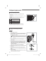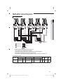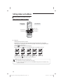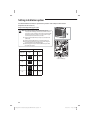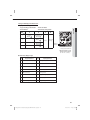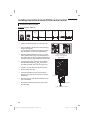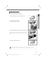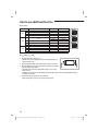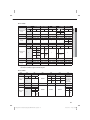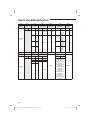
1
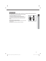
mqtvGhqWZ]qjq\ptluki]_TW\WXZhTWWUGGGZY YWX[TXYTX^GGG㝘㤸GXXa\[a\] AJ036JCJ5** Air Conditioner installation manual imagine the possibilities Thank you for purchasing this Samsung product. EN ES FR DB68-05013A-00 mqtvGhqWZ]qjq\ptluki]_TW\WXZhTWWUGGGZZ YWX[TXYTX^GGG㝘㤸GXXa\[a\] Contents Safety precautions .................................................................................................................................................................................................................................2 Accessories ................................................................................................................................................................................................................................................4 Deciding on where to install the air conditioner .....................................................................................................................................................................4 Space requirement for outdoor unit .............................................................................................................................................................................................6 Indoor/outdoor unit installation drawings ................................................................................................................................................................................8 Refrigerant piping work ......................................................................................................................................................................................................................9 Charging additional refrigerant.................................................................................................................................................................................................... 12 Pump down operation ..................................................................................................................................................................................................................... 12 Method for connecting wires ........................................................................................................................................................................................................ 12 Setting indoor unit address ........................................................................................................................................................................................................... 15 Setting installation option............................................................................................................................................................................................................... 22 Installing transmitter and sub PCB for central control ....................................................................................................................................................... 24 How to use additional function .................................................................................................................................................................................................... 26 Test run and final check .................................................................................................................................................................................................................... 29 Troubleshooting .................................................................................................................................................................................................................................. 30 Safety precautions (Carefully follow the precautions listed below because they are essential to guarantee the safety of the equipment.) WARNING • Always disconnect the air conditioner from the power supply before servicing it or accessing its internal components. • Verify that installation and testing operations are performed by qualified personnel. • Verify that the air conditioner is not installed in an easily accessible area. GENERAL INFORMATION X Carefully read the content of this manual before installing the air conditioner and store the manual in a safe place in order to be able to use it as reference after installation. X For maximum safety, installers should always carefully read the following warnings. X Store the operation and installation manual in a safe location and remember to hand it over to the new owner if the air conditioner is sold or transferred. X This manual explains how to install an indoor unit with a split system with two SAMSUNG units. The use of other types of units with different control systems may damage the units and invalidate the warranty. The manufacturer shall not be responsible for damages arising from the use of non compliant units. X The manufacturer shall not be responsible for damage originating from unauthorized changes or the improper connection of electric and hydraulic lines. Failure to comply with these instructions or to comply with the requirements set forth in the “Operating limits” table, included in the manual, shall immediately invalidate the warranty. X The air conditioner should be used only for the applications for which it has been designed: the indoor unit is not suitable to be installed in areas used for laundry. X Do not use the units if damaged. If problems occur, switch the unit off and disconnect it from the power supply. X In order to prevent electric shocks, fires or injuries, always stop the unit, disable the protection switch and contact SAMSUNG’s technical support if the unit produces smoke, if the power cable is hot or damaged or if the unit is very noisy. X Always remember to inspect the unit, electric connections, refrigerant tubes and protections regularly. These operations should be performed by qualified personnel only. X The unit contains moving parts, which should always be kept out of the reach of children. 2 mqtvGhqWZ]qjq\ptluki]_TW\WXZhTWWUGGGY YWX[TXYTX^GGG㝘㤸GXXa\[a[Y Safety precautions GENERAL INFORMATION ENGLISH X Do not attempt to repair, move, alter or reinstall the unit. If performed by unauthorized personnel, these operations may cause electric shocks or fires. X Do not place containers with liquids or other objects on the unit. X All the materials used for the manufacture and packaging of the air conditioner are recyclable. X The packing material and exhaust batteries of the remote control(optional) must be disposed of in accordance with current laws. X The air conditioner contains a refrigerant that has to be disposed of as special waste. At the end of its life cycle, the air conditioner must be disposed of in authorized centers or returned to the retailer so that it can be disposed of correctly and safely. X This appliance is not intended for use by persons(including children) with reduced physical, sensory or mental capabilities, or lack of experience and knowledge, unless they have been given supervision or instruction concerning use of the appliance by a person responsible for their safety ; Young children should be supervised to ensure that they do not play with the appliance. INSTALLING THE UNIT IMPORTANT: When installing the unit, always remember to connect first the refrigerant tubes, then the electrical lines. Always disassemble the electric lines before the refrigerant tubes. X Upon receipt, inspect the product to verify that it has not been damaged during transport. If the product appears damaged, DO NOT INSTALL it and immediately report the damage to the carrier or retailer (if the installer or the authorized technician has collected the material from the retailer.) X After completing the installation, always carry out a functional test and provide the instructions on how to operate the air conditioner to the user. X Do not use the air conditioner in environments with hazardous substances or close to equipment that release free flames to avoid the occurrence of fires, explosions or injuries. X To prevent injury when accidentally touching the indoor unit fan, install the indoor unit at least 2.5m(8.2ft) above the floor. X The air conditioner should be used only for the applications for which it has been designed: the indoor unit is not suitable to be installed in areas used for laundry. X Our units must be installed in compliance with the spaces indicated in the installation manual to ensure either accessibility from both sides or ability to perform routine maintenance and repairs. The units’ components must be accessible and that can be disassembled in conditions of complete safety either for people or things. For this reason, where it is not observed as indicated into the Installation Manual, the cost necessary to reach and repair the unit (in safety, as required by current regulations in force) with slings, trucks, scaffolding or any other means of elevation won’t be considered in-warranty and charged to end user. POWER SUPPLY LINE, FUSE OR CIRCUIT BREAKER X Always make sure that the power supply is compliant with current safety standards. Always install the air conditioner in compliance with current local safety standards. X Always verify that a suitable grounding connection is available. X Verify that the voltage and frequency of the power supply comply with the specifications and that the installed power is sufficient to ensure the operation of any other domestic appliance connected to the same electric lines. X Always verify that the cut-off and protection switches are suitably dimensioned. X Verify that the air conditioner is connected to the power supply in accordance with the instructions provided in the wiring diagram included in the manual. X Always verify that electric connections (cable entry, section of leads, protections…) are compliant with the electric specifications and with the instructions provided in the wiring scheme. Always verify that all connections comply with the standards applicable to the installation of air conditioners. 3 mqtvGhqWZ]qjq\ptluki]_TW\WXZhTWWUGGGZ YWX[TXYTX^GGG㝘㤸GXXa\[a[Y Accessories The following accessories are supplied with the air conditioner. Accessories in the outdoor unit case 3-wire Power Cable (option) 2-wire Assembly Cable (option) Drain Plug Installation Manual Rubber Leg Flare Nuts, 15.88 mm(5/8 inch) outer pipe diameter Flare Nuts, 9.52 mm(3/8 inch) outer pipe diameter Tube connector (Pipe 12.70 mm(1/2 inch); Bolt 9.52 mm(3/8 inch)) Tube connector (Pipe 12.70 mm(1/2 inch); Bolt 15.88 mm(5/8 inch)) Energy Label 86*RYHUQPHQW )HGHUDOODZSURKLELWVUHPRYDORIWKLVODEHOEHIRUHFRQVXPHUSXUFKDVH 6DPVXQJ(OHFWURQLFV&R/WG 0RGHO$--&-&+ +HDWLQJ&DSDFLW\%WXK &RROLQJ&DSDFLW\%WXK +HDW3XPS &RROLQJDQG+HDWLQJ 6SOLW6\VWHP &RROLQJ (IILFLHQF\5DWLQJ6((5 /HDVW(IILFLHQW 0RVW(IILFLHQW 5DQJHRI6LPLODU0RGHOV 6HDVRQDO(QHUJ\(IILFLHQF\5DWLR +HDWLQJ (IILFLHQF\5DWLQJ+63) 7KLVV\VWHP¶V HIILFLHQF\UDWLQJVGHSHQG RQWKHFRLO\RXUFRQWUDFWRU LQVWDOOVZLWKWKLVXQLW7KH KHDWLQJHIILFLHQF\UDWLQJ YDULHVVOLJKWO\LQGLIIHUHQW JHRJUDSKLFUHJLRQV$VN \RXUFRQWUDFWRUIRUGHWDLOV /HDVW(IILFLHQW 0RVW(IILFLHQW )RUHQHUJ\FRVWLQIRYLVLW SURGXFWLQIRHQHUJ\JRY 5DQJHRI6LPLODU0RGHOV +HDWLQJ6HDVRQDO3HUIRUPDQFH)DFWRU ※ Attach Energy Label to the outdoor unit properly when installing. 䭭 The 3-wire power cable and the 2-wire assembly cable are optional. If these cables are not supplied, use the standard cable approved by IEC standard. Please, check “Method for connecting wires” section. Deciding on where to install the air conditioner When deciding on the location of the air conditioner with the owner, the following restrictions must be taken into account. General Do NOT install the air conditioner in a location where it will come into contact with the following elements : ◆ Combustible gases ◆ Saline air ◆ Machine oil ◆ Sulphide gas ◆ Special environmental conditions ◆ The air conditioner should be used only for the applications for which it has been designed : the indoor unit is not suitable to be installed in areas used for laundry. If you must install the unit in such conditions, first consult your dealer. Outdoor Unit ◆ The outdoor unit must NEVER be placed on its side or upside down, as the compressor lubrication oil will run into the cooling circuit and seriously damage the unit. ◆ Choose a location that is dry and sunny, but not exposed to direct sunlight or strong winds. ◆ Do not block any passageways or thoroughfares. ◆ Choose a location where the noise of the air conditioner when running and the discharged air do not disturb any neighbours. 4 mqtvGhqWZ]qjq\ptluki]_TW\WXZhTWWUGGG[ YWX[TXYTX^GGG㝘㤸GXXa\[a[Y Outdoor uniV Sea breeze ENGLISH ◆ Choose a position that enables the piping and cables to be easily connected to the indoor unit and the recommended length will be respected. ◆ Install the outdoor unit on a flat, stable surface that can support its weight and does not generate any unnecessary noise and vibration. ◆ Position the outdoor unit so that the air flow is directed towards the outside, as indicated by the arrows on the top of the unit. ◆ Maintain sufficient clearance around the outdoor unit, as indicated in page 8. ◆ Make sure that the water dripping from the drain hose runs away correctly and safely. ◆ When installing the outdoor unit near seashore, make sure it is not directly exposed to sea breeze. If you can not find a adequate place without direct see breeze, protection wall should be constructed. ◆ Install the outdoor unit in a place (such as near buildings etc.) where it can be prevented from sea breeze which can damage the outdoor unit. Outdoor unit Sea breeze Sea Sea ◆ If you cannot avoid installing the outdoor unit by the seashore, construct a protection wall around to block the sea breeze. Protection wall Outdoor unit Sea breeze Sea Protection wall should be constructed with a solid material such as concrete to block the sea breeze and the height and the width of the wall should be 1.5 times larger than the size of the outdoor unit. Also, secure over 700 mm(27.5 inch) between the protection wall and the outdoor unit for exhausted air to ventilate. ◆ Install the outdoor unit in a place where water can drain smoothly. ※ If you cannot find a place satisfying above conditions, please contact manufacturer. Make sure to clean the sea water and the dust on the outdoor unit heat exchanger and spread corrosion inhibitor on heat exchanger. (At least one time per one year.) ◆ You have just purchased a Free Joint Multi air conditioner and it has been installed by your installation specialist. ◆ This device must be installed according to the national electrical rules. ◆ Max input power & current is measured according to IEC standard and input power & current is measured according to ISO standard. ◆ More than 2 indoor units should be installed when you use Free Joint Multi air conditioner. ◆ Our units must be installed in compliance with the spaces indicated in the installation manual to ensure either accessibility from both sides or ability to perform routine maintenance and repairs. The units’ components must be accessible and that can be disassembled in conditions of complete safety either for people or things. For this reason, where it is not observed as indicated into the Installation Manual, the cost necessary to reach and repair the unit (in safety, as required by current regulations in force) with slings, trucks, scaffolding or any other means of elevation won’t be considered in-warranty and charged to end user. ◆ With an outdoor unit having net weight upper than 60 kg(132 lbs), we suggest do not install it suspended on wall, but considering floor standing one. ◆ When the outdoor unit is installed near seashore or in a place where sulfuric acid gas may leak, corrosion may occur in outdoor unit and cause product malfunction. 5 mqtvGhqWZ]qjq\ptluki]_TW\WXZhTWWUGGG\ YWX[TXYTX^GGG㝘㤸GXXa\[a[Z Space requirement for outdoor unit A When installing 1 outdoor unit ※ When the air outlet is towards the wall 2000(80) or more 600(24) or more ※ The upper part of the outdoor unit and the air outlet is towards the wall 300(12) or more 1500(60) or more 600(24) or more ※ When 3 sides of the outdoor unit are blocked by the wall 300(12) or more 300(12) or more 1500(60) or more 300(12) or more ※ When the air outlet is opposite the wall 1500(60) or more 300(12) or more Unit : mm (inch) ※ The upper part of the outdoor unit and the air outlet is opposite the wall ※ When front and rear side of the outdoor unit is towards the wall 1500(60) or more When installing more than 1 outdoor unit ※ When the air outlet is towards the wall 6 mqtvGhqWZ]qjq\ptluki]_TW\WXZhTWWUGGG] YWX[TXYTX^GGG㝘㤸GXXa\[a[Z When installing more than 1 outdoor unit 600(24) or more 600(24) or more 600(24) or more ※ When 3 sides of the outdoor unit are blocked by the wall 600(24) or more 600(24) or more 1500(60) or more 300(12) or more 300(12) or more ENGLISH 300(12) or more Unit : mm (inch) ※ When front and rear side of the outdoor unit is towards the wall 1500(60) or more 600(24) or more 3000(120) or more 3000(120) or more 300(12) or more ※ When front and rear side of the outdoor unit is towards the wall Fixing the unit in position 1. Position the outdoor unit so that the air flow is directed towards the outside, as indicated by the arrows on the top of the unit. 2. Attach the outdoor unit to the appropriate support using anchor bolts. ◆ The earthing wire for the telephone line cannot be used to earth the air conditioner. 3. If the outdoor unit is exposed to strong winds, install shield plates around the outdoor unit, so that the fan can operate correctly. 360 mm(14.17 inch) The outdoor unit must be installed on a rigid and stable base to avoid any increase in the noise level and vibration, particularly if the outdoor unit is to be installed close to a neighbour. If it is to be installed in a location exposed to strong winds or at a height, the unit must be fixed to an appropriate support (wall or ground). 620 mm(24.40 inch) Rubber leg 䭭 Certainly fix up its rubber leg in order to prevent its vibration and noise. 7 mqtvGhqWZ]qjq\ptluki]_TW\WXZhTWWUGGG^ YWX[TXYTX^GGG㝘㤸GXXa\[a[Z A Indoor/outdoor unit installation drawings ◆ Piping outside diameter Indoor unit Outdoor unit Power supply ø, V, Hz **007/009/ 012/018/024** AJ036JCJ5** 1, 208-230, 60 Outside diameter Liquid Gas Unit **007/009/012** 3/8" 1/4" **018** **024** 1/2" 5/8" (h) (H) A B C D E Main power switch ◆ Piping length and the height Dimension Composition 1 Room max length 25 m(82 ft) A, B, C, D, E 5 Room total max length 80 m(262 ft) A+B+C+D+E Max height between Max height between indoor unit & outdoor unit indoor units 15 m(49 ft) 7.5 m(25 ft) (H) (h) Make at least one round : It will reduce noise and vibration ※ The appearance of the unit may be different from the diagram depending on the model. 8 mqtvGhqWZ]qjq\ptluki]_TW\WXZhTWWUGGG_ YWX[TXYTX^GGG㝘㤸GXXa\[a[Z A Refrigerant piping work Installing drain hose 1. Insert the drain plug into the drain hole on the underside of the outdoor unit. 2. Connect the drain hose to the drain plug. 3. Ensure that condensation draining is adequate. ENGLISH While heating, ice may accumulate. During the process of defrosting, check if condensation draining is adequate. For adequate draining, do the following : Drain hole $RAINHOLE Cutting/extending the piping 1. Make sure that you have the required tools available (pipe cutter, reamer,flaring tool and pipe holder). 2. If you wish to shorten the piping, cut it using a pipe cutter, taking care to ensure that the cut edge remains at a 90° angle with the side of the pipe,and referring to the illustrations below for examples of edges cut correctlyand incorrectly. Oblique Rough Burr 3. To prevent any gas from leaking out, remove all burrs at the cut end of the pipe, using a reamer. 4. Slide a flare nut on to the pipe and modify the flare. Outer Diameter (D) Thickness Depth (A) ø6.35 mm(1/4") 0.8 mm(0.03") 1.3 mm(0.05") ø9.52 mm(3/8") 0.8 mm(0.03") 1.8 mm(0.07") ø12.70 mm(1/2") 0.8 mm(0.03") 2.0 mm(0.08") ø15.88 mm(5/8") 0.8 mm(0.03") 2.2 mm(0.09") 5. Check that the flaring is correct, referring to the illustrations below for examples of incorrect flaring. Correct Inclined Damaged Surface Cracked Uneven Thickness 6. Align the pipes to be connected and tighten the flare nuts first manually and then with a torque wrench, applying the following torque. Outer Diameter (D) Thickness ø6.35 mm(1/4") ø9.52 mm(3/8") ø12.70 mm(1/2") ø15.88 mm(5/8") 0.8 mm(0.03") 0.8 mm(0.03") 0.8 mm(0.03") 0.8 mm(0.03") Torque N·m 14~18 34~42 49~61 68~82 ft·lb(kgf·cm) 10.1~13.0 (140~180) 25.3~31.1 (350~430) 36.2~44.8 (500~620) 49.9~60.0 (690~830) 7. For further details on how to connect up to the outdoor unit and purge the circuit, refer to page 10. 䭭 In case welding the pipe, the gas nitrogen must be blown into the parts. 9 mqtvGhqWZ]qjq\ptluki]_TW\WXZhTWWUGGG` YWX[TXYTX^GGG㝘㤸GXXa\[a[[ A Refrigerant piping work Connecting refrigerant pipe Follow different orders depending on the capacity of indoor units. **007/009/012** ◆ Install pipes between indoor and outdoor units orderly as [A→B →C→D→E]. OUTDOOR UNIT A unit B unit **018/024** ◆ Install pipes between indoor and outdoor units orderly as [ C→D→E]. Port A B C D E C unit D unit Indoor unit E unit **007/009/012** **007/009/012**1) **018** **024**2) 1) Use tube connector (pipe 12.70 mm(1/2"), bolt 9.52 mm(3/8")) 2) Use tube connector (pipe 12.70 mm(1/2"), bolt 15.88 mm(5/8")) Purging air and checking gas leakage Purging air 1 Check the piping connections. 2 Connect the charging hose of low pressure side of manifold gauge to the packed valve having a service port (5/8” Packed valve) as shown at the figure (Value stem: 1/2” - 20UNF). WARNING ◆ Make the electrical connection and leave the system into “stand by mode”. Do not turn on the system! This is necessary for better vacuum operation (full OPEN position of Electronic Expansion Valve - EEV -). 3 Open the valve of the low pressure side of manifold gauge counter clockwise. 4 Purge the air from the system using vacuum pump for about 30 minutes. - Close the valve of the low pressure side of manifold gauge clockwise. - Make sure that pressure gauge show -0.1MPa(-76cmHg) after about 30 minutes. This procedure is very important in order to avoid gas leak. - Turn off the vacuum pump. - Remove the hose of the low pressure side of manifold gauge. Vacuum Pump Valve stem 5 Set valve cork of both liquid side and gas side of packed valve to the open position. 6 Mount the valve stem nuts and the service port cap to the valve, and tighten them at the torque of 183 kgf•cm(18 N•m) with a torque wrench. 7 Check for gas leakage. - At this time, especially check for gas leakage from the 3-way valve’s stem nuts, and from the service port cap. Stem cap Service port 10 mqtvGhqWZ]qjq\ptluki]_TW\WXZhTWWUGGGXW YWX[TXYTX^GGG㝘㤸GXXa\[a[[ Checking gas leakage LEAK TEST WITH NITROGEN (before opening valves) In order to detect basic refrigerant leaks, before recreating the vacuum and recirculating the R-410A, it’s responsible of installer to pressurize the whole system with nitrogen (using a cylinder with pressure reducer) at a pressure above 30 bar (gauge). ENGLISH Before completing the installation (insulation of the cables, hose and piping and fixing of the indoor unit to the installation plate), you must check that there are no gas leaks. LEAK TEST WITH R-410A (after opening valves) Before opening valves, discharge all the nitrogen into the system and create vacuum according to page 10. After opening valves, check leaks using a leak detector for refrigerant. 11 mqtvGhqWZ]qjq\ptluki]_TW\WXZhTWWUGGGXX YWX[TXYTX^GGG㝘㤸GXXa\[a[\ Charging additional refrigerant If you install the excessive length of pipe, add additional refrigerant as 20 g(0.04 lbs) per unit meter ; refer to the table below. Refer to the Service Manual for more details on this operation. Total connecting pipe length (L) Adding refrigerant LTd40 m(131 ft) LT>40 m(131 ft) Chargeless (LT- 40 m(131 ft) )x 20 g(0.04 lbs) Pump down operation PUMP DOWN (before disconnecing the refrigerant connections for unit repair, removal or disposal) Pump-down is an operation intended to collect all the system refrigerant in the outdoor unit. This operation must be carried out before disconnecting the refrigerant pipe in order to avoid refrigerant loss to the atmosphere. 1. Shut off all the liquid valve with the Allen wrench. 2. Turn the system on in cooling with fan operating at high velocity. (Compressor will immediately start, provided 3 minutes have elapsed since the last stop). 3. After 2 minutes of operation, shut off the suction valves with the allen wrench. 4. Turn the system off and switch mains supply off. 5. Disconnect pipes. After disconnection, protect valves and tubing ends from dust. 6. Compressor damage may occur if run at a negative suction pressure. ※ The designs and shape are subject to change according to the model. Method for connecting wires Selecting wires size B D d1 E F L d2 t Nominal Nominal dimensions dimensions Standard Standard Standard Standard for screw dimension Allowance dimension Allowance dimension Allowance Min. Min. Max. dimension Allowance Min. for cable [mm(inch)] [mm2(inch2)] [mm(inch)] [mm(inch)] [mm(inch)] [mm(inch)] [mm(inch)] [mm(inch)] [mm(inch)] [mm(inch)] 0.75~1.5 ±0.2 4(0.15) 6.6(0.25) (0.0011~0.002) (±0.007) 3.4(0.13) +0.3(+0.011) ±0.2 4.1 6 16 1.7(0.06) 4.3(0.16) -0.2(-0.007) (±0.007) (0.16) (0.24) (0.62) ±0.2 (±0.007) 4(0.15) 8.5(0.33) ±0.2 4(0.15) 9.5(0.37) (±0.007) 5.6(0.22) +0.3(+0.011) ±0.2 6 5 20 3.4(0.13) 4.3(0.16) -0.2(-0.007) (±0.007) (0.24) (0.19) (0.78) ±0.2 0.9 (±0.007) (0.035) 4(0.006) 0.7 (0.02) 12 mqtvGhqWZ]qjq\ptluki]_TW\WXZhTWWUGGGXY YWX[TXYTX^GGG㝘㤸GXXa\[a[\ Method for connecting wires A Connecting wires A-unit ) //) C-unit ) //) D-unit ) //) E-unit //) ) ENGLISH //) B-unit ) Indoor unit Assembly cable ) ) Earth terminal % & % ) ) Earth terminal ) ) Earth terminal & % ) ) Earth terminal ) ) Earth terminal & ) ) Earth terminal ) ) % Earth terminal ) ) % & Earth terminal ) ) Earth terminal & ) ) Earth terminal Outdoor unit $ % / / / / / / / / / / Power cable to indoor units ) ) ) ) % & Communication cable to indoor units ' ! Cable Type : A " Cable Type : B # Cable Type : C / / Main Power Supply cable Earth terminal $ Specification for circuit breaker and power supply cord 䭭 䭭 䭭 䭭 Power supply cord is not supplied with air conditioner. Select the power supply cord in accordance with relevant local and national regulations. Wire size must comply with the applicable local and national code. Specifications for local wiring power supply cord and branch wiring are in compliance with local cord. The specification for cables : Model Main Power Supply Cable Indoor Power Supply Cable Specification 3G, 4.0 mm2 AJ036JCJ5CH/ (0.0062 inch2) or AA more, H07RN-F Communication Cable Type Specification Type Specification Type A 3G, 1.0 mm2 (0.0015 inch2) or more, H07RN-F B 2G, 0.75 mm2 (0.0011 inch2) or more, H07RN-F C FUSE MCCB Type GL 25 A Frame : 35 A Trip : 25 A 25 A 䭭 Connect the power cable to the auxiliary circuit breaker. If every pole fails to connect to the power supply, it must be incorporated in a wire with a contact opening of ≥0.12inch. 13 mqtvGhqWZ]qjq\ptluki]_TW\WXZhTWWUGGGXZ YWX[TXYTX^GGG㝘㤸GXXa\[a[\ Tightening power terminal 䭭 䭭 䭭 䭭 Connect the cables to the terminal board using the compressed ring terminal. Use rated cables only. Connect the cables with driver and wrench that can apply the rated torque to the screws. Make sure that appropriate tightening torque is applied for cable connection. If the terminal is loose, arc heat may occur and cause fire and if the terminal is connected too firmly, terminal may get damaged. Screw M4 Tighten Torque 12.0~18.0 kgf · cm 1.2~1.8 N · m (0.87~1.3 ft · lb) Position L1, L2, F1, F2 Method for connecting wires Checking correct earthing If the power distribution circuit does not have an earth or the earth does not comply with specifications, an earthing electrode must be installed. The corresponding accessories are not supplied with the air conditioner. Select an earthing electrode that complies with the specifications given in the illustration opposite. 2. Determine a suitable location for the earthing electrode : ◆ In damp hard soil rather than loose sandy or gravel soil that has a higher earthing resistance. ◆ Away from underground structures or facilities, such as gas pipes, water pipes, telephone lines and underground cables. ◆ At least two meters away from a lightening conductor earthing electrode and its cable. 䭭 The earthing wire for the telephone line cannot be used to earth the air conditioner. 3. Dig a hole of the size indicated in the illustration opposite, drive the earthing electrode into position and cover the top of the electrode with the excavated soil. 4. Install a green/yellow insulated earthing wire (Φ1.6 mm(0.06 inch), section 2 mm2(0.003 inch2) or greater) : Carbon plastic Steel core PVC-insulated green /yellow wire, 2mm² x 3.5m(11.5ft) To earthing screw 50 cm(1.6 ft) 30 cm (1 ft) 1. ◆ If the earthing wire is too short, connect an extension lead, soldering the connection and wrapping it with insulating tape (Do not bury the soldered connection.) ◆ Secure the earthing wire in position with staples. If the earthing electrode is installed in an area of heavy traffic, its wire must be connected securely.j 5. Carefully check the installation, by measuring the earthing resistance with an earthing resistance tester. If the resistance is above the required level(Example:100Ω), drive the earthing electrode deeper into the ground or increase the number of earthing electrodes. 6. Connect the earthing wire to the earthing screw on the air conditioner. 14 mqtvGhqWZ]qjq\ptluki]_TW\WXZhTWWUGGGX[ YWX[TXYTX^GGG㝘㤸GXXa\[a[] A Setting indoor unit address Setting indoor unit address automatically ENGLISH " to appear on the display of ◆ Switch the system on and wait for code " the external unit (this requires approximately 60 seconds **). "displays, press once the red button (K1) shown on ◆ As soon as code " the figure on the side of the page : WARNING ◆ ◆ Position DIP switch 1 to ON. If the quantity of indoor units connected is lower than maximum connectable to outdoor unit, the rotary switch SW01 has to be positioned to select a number equal to indoor units’ quantity you connected. ◆ After the operations described above have been performed, the system starts in Cooling or Heating mode, depending on the external ambient temperature. After a few minutes (from a minimum of 3 to 5 minutes for the internal unit), the system stops automatically, completing the self-test and addressing procedure. " " appears on the display of the external unit. " (that confirms the correct execution ◆ 20 seconds after the display of " of the procedure), the following codes (if four internal units are connected) display in sequence on the display of the external unit: Display 1 Display 2 Display 1 Display 2 K1 DIP Switch Rotary Switch <Display of the external unit> ※ During the initial 60 seconds, display 1 shows in sequence : 00 ¤ 01¤02 ¤...15¤ 00... Description The outdoor unit is communicating correctly with the indoor unit connected to refrigerant pipe A. The outdoor unit is communicating correctly with the indoor unit connected to refrigerant pipe B. The outdoor unit is communicating correctly with the indoor unit connected to refrigerant pipe C. The outdoor unit is communicating correctly with the indoor unit connected to refrigerant pipe D. The outdoor unit is communicating correctly with the indoor unit connected to refrigerant pipe E. At this point it is possible to start the internal units in the desired mode "doesn’t display, the procedure has failed and it is therefore 䭭 If " necessary to read ALL the operator’s manual before repeating the operating described in steps 1-2-3-4. 15 mqtvGhqWZ]qjq\ptluki]_TW\WXZhTWWUGGGX\ YWX[TXYTX^GGG㝘㤸GXXa\[a[] A Setting indoor unit address Setting indoor unit address manually Step 1 Review all the following elements in the installation: ◆ Installation site strength ◆ Piping connection tightness to detect any gas leakage ◆ Connection wiring ◆ Heat-resistant insulation of the piping ◆ Drainage ◆ Earthing wire connection Step 2 IMPORTANT! Before selecting switch, turn off the system power supply Rotary Switch DIP Switch Display 2 Display 1 K1, K2, K3, K4 WARNING ◆ When setting the indoor unit address manually, position DIP switch 1 to OFF. ◆ Adjust the rotary switch to the number of the connected indoor unit. Step 3 Follow of indication reported into table below for indoor unit addressing 䭭 Refer to page 17 for indoor unit address setting. Step 4 Turn on the system power supply and waiting for 60 seconds after estabilishing communication between outdoor and indoor units. During this phase, the left display of outdoor unit display PCB “DIS01” will count from 00--01--02 to 15. Estabilished communication the left display will count sequentially: 00--communication with indoor unit A; 01--communication with indoor unit B; 02--communication with indoor unit C; 03--communication with indoor unit D; 04--communication with indoor unit E; ※ In case of Manual address mode,you can do pipe check operation for check whether you connect the pipes correctly or not. But you need set indoor address switch yourselves. 16 mqtvGhqWZ]qjq\ptluki]_TW\WXZhTWWUGGGX] YWX[TXYTX^GGG㝘㤸GXXa\[a[] ROTARY SWITCH “SW02” POSITION ACCORDING TO REFRIGERANT CIRCUIT CONNECTED ( 0=A; 1=B; 2=C; 3=D; 4=E ) A unit Att. "B" Att. "C" Att. "D" Att. "E" ENGLISH Indoor Unit SW02 Att. "A" OUTDOOR UNIT B unit C unit D unit E unit TYPE PICTURE MODEL TO SET ADDRESSING MANUALLY BY ROTARY SWITCH “SW02” SW SLIM DUCT AJ009JNLD** AJ012JNLD** AJ018JNLD** 17 mqtvGhqWZ]qjq\ptluki]_TW\WXZhTWWUGGGX^ YWX[TXYTX^GGG㝘㤸GXXa\[a[^ A Setting indoor unit address Setting indoor unit address manually Setting option (AJ**JNND**/AJ**JNAD**) Entering mode for setting option Option setting mode Mode change High Temp Button High Fan Button Low Temp Button Low Fan Button X Setting option 1. Remove batteries from the remote controller. 2. Insert batteries and enter the option setting mode while pressing High Temp button and Low Temp button. 3. Each time you press Low Fan button, 7-seg on left side is increased by “1” and each time you press High Fan button, 7-seg on right side is increased by “1”. button to move to the next setteing page. 4. You press 5. After setting option, press button to check whether the option code you input is correct or not. ¤ ¤ ¤ ¤ ¤ ¤ ¤ ¤ 6. Press operation button ¤ with the direction of remote control for set. • SEG1, SEG7, SEG13, SEG19 are not set as page option. • Set the SEG1, SEG7 as ON status and SEG13, SEG19 as OFF status. EX) Set the each option separately since you cannot set the ADDRESS setting and indoor unit installation setting option at the same time. 18 mqtvGhqWZ]qjq\ptluki]_TW\WXZhTWWUGGGX_ YWX[TXYTX^GGG㝘㤸GXXa\[a[_ The procedure of setting option Operation Indication ENGLISH * Step 1 1. Remove the batteries from the remote controller. 2. Insert batteries while pressing High Temp Button and Low Temp Button. * Step 2 1. Press Low Fan button to enter SEG2 value. 2. Press High Fan button to enter SEG3 value. * Step 3 Press Mode button to be change to Cool mode in the ON status. 1. Press Low Fan button to enter SEG4 value. 2. Press High Fan button to enter SEG5 value. * Step 4 Press Mode button to be changed to DRY mode in the ON status. 1. Press Low Fan button to enter SEG6. 2. Press High Fan button to enter SEG8. * Step 5 Press Mode button to be changed to FAN mode in the ON status. 1. Press Low Fan button to enter SEG9 value. 2. Press High Fan button to enter SEG10 value. * Step 6 Press Mode button to be changed to HEAT mode in the ON status. 1. Press Low Fan button to enter SEG11 value. 2. Press High Fan button to enter SEG12value * Step 7 Press Mode button to be changed to AUTO mode in the OFF status. 1. Press Fan button to enter SEG14 value. 2. Press High Fan button to enter SEG15 value. * Step 8 Press Mode button to be changed to Cool mode in the OFF status. 1. Press Low Fan button to enter SEG16 value. 2. Press High Fan button to enter SEG17 value. * Step 9 Press Mode button to be changed to DRY mode in the OFF status. 1. Press Low Fan button to enter SEG18 value. 2. Press High Fan button to enter SEG20 value. * Step 10 Press Mode button to be changed to FAN mode in OFF status 1. Press Low Fan button to enter SEG21 value. 2. Press High Fan button to enter SEG22 value. * Step 11 Press Mode button to be changed to HEAT mode in the OFF status 1. Press Low Fan button to enter SEG23 value. 2. Press High Fan button to enter SEG24 value. * Step 12 Press Mode button to check whether the option code you entered is correct or not. Press operation button to enter option. 19 mqtvGhqWZ]qjq\ptluki]_TW\WXZhTWWUGGGX` YWX[TXYTX^GGG㝘㤸GXXa\[a[_ A Setting indoor unit address Setting indoor unit address manually Setting an indoor unit address (MAIN/RMC) 1. Check whether power is supplied or not. - When the indoor unit is not plugged in, there should be additional power Indoor Unit supply in the indoor unit. 1(L) 2. The panel (display ) should be connected to an indoor unit to receive option. 2(N) 3. Before installing the indoor unit, assign an address to the indoor unit according to the air conditioning system plan. 4. Assign an indoor unit address by wireless remote controller. - The initial setting status of indoor unit ADDRESS (MAIN/RMC) is "0A0000-100000-200000-300000" - There is no need to assign extra ADDRESS for 1:1 installation between indoor unit and outdoor unit. F2 F1 Option No. : 0AXXXX-1XXXXX-2XXXXX-3XXXXX Option Explanation SEG1 PAGE SEG2 SEG3 MODE Setting Main address SEG4 SEG5 SEG6 100-digit of indoor 10-digit of indoor unit address unit A single digit of indoor unit Remote Controller Display Indication Details Indication Details Indication Details Indication Details Indication Details Indication Details 0 Indication and Details 0 A Option SEG7 SEG8 Explanation PAGE No Main address Main address 1 setting mode SEG9 Setting RMC address 0~9 100-digit SEG10 0~9 10-digit SEG11 Group channel(*16) 0~9 A single digit SEG12 Group address Remote Controller Display Indication Details Indication Details Indication and Details Indication Details Indication Details Indication Details Indication Details 0 No RMC address 1 RMC address setting mode 1 RMC1 1~F RMC2 1~F ※ You must set RMC address setting mode when using the centralized control . 20 mqtvGhqWZ]qjq\ptluki]_TW\WXZhTWWUGGGYW YWX[TXYTX^GGG㝘㤸GXXa\[a[` ENGLISH • When “A”~”F” is entered to SEG4~6, the indoor unit MAIN ADDRESS is not changed. • If you set the SEG 3 as 0, the indoor unit will maintain the previous MAIN ADDRESS even if you input the option value of SEG4~6. • If you set the SEG 9 as 0, the indoor unit will maintain previous RMC ADDRESS even if you input the option value of SEG11~12. 5. The MAIN address is for commnication between the indoor unit and the outdoor unit. Therefore, you must set it to operate the air conditioner properly. 21 mqtvGhqWZ]qjq\ptluki]_TW\WXZhTWWUGGGYX YWX[TXYTX^GGG㝘㤸GXXa\[a[` A Setting installation option It could take maximum 60 minutes to operate for the protection of the compressor if the outdoor temperature is below -5 °C(23 °F). Ampere Limit Setting & Changing Procedure ◆ Do not adjust the “Ampere Limit Switch(DIP Switch)”, if it’s not necessary : before modifying it, evaluate the total number of electric and electronics loads consumption and use “Ampere limits switch(DIP Switch)” just as emergency solution or in case the system is anyway oversized compared to real thermal load needed. ◆ “Ampere Limit Switch(DIP Switch)” is initially set to the default value (table below). ◆ “Ampere Limit Switch(DIP Switch)” is on the PCB of outdoor unit. ◆ Contact the authorized service technician or dealer for setting and changing the “Ampere Limit Switch(DIP Switch)”. ◆ Before changing the “Ampere Limit Switch(DIP Switch)”, turn off the main power of the system. WARNING Ampere AJ036JCJ5** Switch Selection Switch 23A 3 4 On On 2)) 20A DIP Switch <Outdoor PCB Display> On Off Off On Off Off 2)) 18A 2)) 16A 2)) 22 mqtvGhqWZ]qjq\ptluki]_TW\WXZhTWWUGGGYY YWX[TXYTX^GGG㝘㤸GXXa\[a[` Settings of PCB Display of the Outdoor unit ◆ Key Options of PCB Display - K1 : pipe checking operation button - K3 : Reset button K1 K2 1 Pipe Checking Operation (Display: ) Heat Mode Try run (Display: ) 2 - Refrigerant Charging ) (Display: 3 - Cool Mode Try run (Display: ) - Pump down ) (Display: Push 4 K3 K4 Reset View mode change ENGLISH Key - K2 : Function button - K4 : View mode change button Display 1 Display 2 K1 K2 K3 K4 ※ Heat and Cool Mode Try run functions are just For Service Technician <Display of the external unit> ※ During the initial 60 seconds, display 1 shows in sequence: 00→ 01→02 →...15→ 00... ◆ K4 View mode Display changes Push Display Explanation Push Display Explanation 0 Present Compressor Frequency 8 Discharge temperature 1 Target Compressor Frequency 9 OLP temperature 2 EEV0 current step 10 Condenser temperature 3 EEV1 current step 11 Outdoor temperature 4 EEV2 current step 12 Running current 5 EEV3 current step 13 Target Discharge temperature 6 EEV4 current step 14 Total capacity of the indoor units 7 Fan RPM (H: high, L: low, Blank: off) 15 Safety Control (just For Service Technician) 23 mqtvGhqWZ]qjq\ptluki]_TW\WXZhTWWUGGGYZ YWX[TXYTX^GGG㝘㤸GXXa\[a\W Installing transmitter and sub PCB for central control A Transmitter installation (optional) Accessories (Transmitter : MIM-B13B) Transmitter MAIN 485 DC Power Cable DC Power Cable Communication Transmitter SUB Communication (12V) (5V) Cable Cable Cable Tie Case R2 R1 R2 R1 R1 R2 1. Turn the power off and take off the cover of the outdoor units. 2. Fix the case with bolts to the side of the control box referring to the figure on the right side. In case of FJM outdoor unit, there is not enough space to fix all parts of transmitter. So you may use transmitter main PCB. 3. Attach the transmitter main PCB to the case, then connect F1/ F2 lines, R1/R2 lines which are upper controller communication cables and DC 12V power cables to the interface module referring to the figure on this page. (Upper controller power should be off.) 4. You must check the position of dip switch on the transmitter's main PCB and the main PCB of AJ***JNLD** indoor units. For AJ***JNND**/AJ***JNAD** indoor units, refer to page 26~28. 5. Assemble a cover of the outdoor unit and turn the power on. 6. Check the communication status. 7. If you install a transmitter to the outdoor unit, every indoor unit which is connected to the outdoor unit can be controlled simultaneously. 8. 9. Fix the case with hinges (Control Box in the outdoor unit) Outdoor unit PCB DC12V supply Each outdoor unit connected to the same centralized controller has its own transmitter. R1 R2 Transmitter MAIN PCB When using the centralized controller, refer to page 26~28 for indoor unit setting. ) ) ) ) Terminal block in the outdoor unit 24 mqtvGhqWZ]qjq\ptluki]_TW\WXZhTWWUGGGY[ YWX[TXYTX^GGG㝘㤸GXXa\[a\Y Sub PCB installation (optional) ENGLISH If indoor unit is AJ***JNAD**, install sub PCB. (Wired remote controller, central remote controller etc.) 1. Turn the power off and remove the cover panel of the indoor unit. 2. Attach the Sub PCB to the Case Sub PCB. 3. Install the Case Sub PCB to the indoor unit. /1 )) Case Sub PCB Sub PCB 4. Find the PCB wire, and connect the wire to the Sub PCB as seen in the picture. /1 )) 5. Connect the wire(remote controller, central remote controller etc) to the Sub PCB. /1 )) 6. Reattach the Cover PCB and the front panel. • The Sub PCB is installed for control by the wired remote controller and central controller. 25 mqtvGhqWZ]qjq\ptluki]_TW\WXZhTWWUGGGY\ YWX[TXYTX^GGG㝘㤸GXXa\[a\[ A to use additional function How ◆ AJ***JNLD** No. SW05 SW06 SW07 K1 K2 K3 K4 Function External room sesor Centralized controller Drain Pump K5 Indoor Temperature Compensation for Heating Mode K6 K7 K8 K9 K10 K11 K12 Filter Time Hot Water Coil External Control External Control Output On Disuse Disuse Disuse +2 °C(35.6 °F) +5 °C(41° F) 1,000h Disuse Disuse Thermal ON K1 K2 K3 K4 Off Use Use Use +5 °C(41 ° F) +2 °C(35.6 °F) 2,000h Use Use Operation ON SW05 K5 K6 K7 K8 SW06 K9 K10 K11 K12 SW07 ◆ AJ***JNND**/AJ***JNAD** 1. Check whether power is supplied or not. - When the indoor unit is not plugged in, there should be additional power supply in the indoor unit. 2. The panel (display) should be connected to an indoor unit to receive option. Indoor Unit 1(L) 2(N) F2 F1 3. Before installing the indoor unit, assign an option to the indoor unit according to the airconditioning system plan. - The default setting of an indoor unit installation option is “02000-100000200000-300000”. - Individual control of a remote controller(SEG20) is the function that controls an indoor unit individually when there is more than one indoor unit. 4. Set the indoor unit option by wireless remote controller. - When entering address option, connect remote controller receiver. 26 mqtvGhqWZ]qjq\ptluki]_TW\WXZhTWWUGGGY] YWX[TXYTX^GGG㝘㤸GXXa\[a\[ ◆ AJ***JNAD** Option Explanation 0 Indication and Details 2 Option Explanation Disuse On/Off 1 control Off 2 control Window 3 On/Off control1) SEG20 0 Thermo ON 1 Operation ON 0 ENGLISH SEG1 SEG2 SEG3 SEG4 SEG5 SEG6 PAGE MODE Central control Indication Details Indication Details Indication Details Indication Details Indication Details Indication Details Indication and 0 Disuse Details 0 2 0 0 0 1 Use Option SEG7 SEG8 SEG9 SEG10 SEG11 SEG12 Explanation PAGE Master/Slave Indication Details Indication Details Indication Details Indication Details Indication Details Indication Details Indication and 0 Slave Details 1 0 0 0 0 1 Master Option SEG13 SEG14 SEG15 SEG16 SEG17 SEG18 Buzzer Explanation PAGE External control External control output Indication Details Indication Details Indication Details Indication Details Indication Details Indication Details Use 0 0 1 Disuse SEG19 SEG21 SEG22 SEG23 SEG24 PAGE Indication and Indication Details Indication Details Indication Details Indication Details Indication Details Indication Details Details 3 0 0 0 0 0 ▶ If you input a number other than 0~4 of the individual control of the indoor unit(SEG20), the indoor is set as "indoor 1". 1) The window on/off function applies to the following unit ◆ AJ***JNND** Option SEG1 SEG2 Explanation PAGE MODE SEG3 Indication Details Indication Details Indication and Details RESERVED 0 2 Option Explanation SEG7 SEG8 PAGE Use of drain pump Indication Details Indication Details 0 Disuse Indication and 1 Use Details 1 Use+3 2 minute delay SEG4 Use of external temperature sensor Indication Details 0 Disuse 1 Use SEG5 Use of central control Indication 0 Details Disuse 1 Use SEG9 SEG10 SEG11 RESERVED RESERVED RESERVED SEG6 RPM setting compensation 0 Not used 1 High ceiling mode 2 High ceiling kit 3 Low noise operation mode SEG12 Master/Slave Indication Details 0 Slave 1 Master 27 mqtvGhqWZ]qjq\ptluki]_TW\WXZhTWWUGGGY^ YWX[TXYTX^GGG㝘㤸GXXa\[a\[ How to use additional function Option Explanation Indication and Details Option SEG13 SEG16 SEG17 PAGE SEG14 SEG15 Use of external Setting the output of control external control Indication Details Indication Details Indication Details S-Plasma ion Buzzer control 0 Disuse 1 ON/OFF Control 2 OFF Control 3 WINDOW Control 0 Thermo on 0 Details Disuse Indication 0 1 2 1 Operation on 1 Use SEG19 SEG22 3 Indoor 4 2 5 °C (41 °F) Details Mixed operation control 1/Use buzzer Mixed operation control 2/ Disuse of buzzer Mixed operation control 2/Use buzzer Mixed operation control 2/ Disuse of buzzer SEG23 2 1000 Hour 6 2000 Hour SEG24 Motion detect sensor RESERVED 4 2 3 SEG20 SEG21 Individual control of Heating setting Explanation PAGE remote controller compensation Indication Details Indication Details Indication Details 0 or 1 Indoor 1 0 Disuse 2 Indoor 2 1 2 °C (35.6 °F) 3 Indoor 3 Indication and Details Indication SEG18 Number of hours using filter Indication Details Indication Details 0. No use (Factory Setting) 1. Standard Mode/Auto Set OFF 30 Min. 2. Standard Mode/Auto Set OFF 60 Min. 3. Standard Mode/Auto Set OFF 120 Min. 4. Standard Mode/Auto Set OFF 180 Min. 5. Premium Mode/Auto Set OFF 30 Min. 6. Premium Mode/Auto Set OFF 60 Min. 7. Premium Mode/Auto Set OFF 120 Min. 8.Premium Mode/Auto Set OFF 180 Min. RESERVED 28 mqtvGhqWZ]qjq\ptluki]_TW\WXZhTWWUGGGY_ YWX[TXYTX^GGG㝘㤸GXXa\[a\\ Test run and final check Test Run ENGLISH 1. Please do cool mode try-run or heat mode try-run. ◆ Cool mode try-run : Push the [K2] button three times. ◆ Heat mode try-run : Push the [K2] button once. 2. After 12 minutes of stationary condition check each indoor unit air treatment. ◆ Cooling mode (indoor unit check) ¤ Inlet air temp. - Outlet air temp : From 10°K to 12°K (indicative delta T) ◆ Heating mode (indoor unit check) ¤ Outlet air temp. - Inlet air temp : From 11°K to 14°K (indicative delta T) 䭭 In heating mode, the indoor fan motor can remain off to avoid cold air blown into conditioned space. Final Check and Explaining operation to the owner Before leaving the premises on which you have installed the air conditioner, you should explain the following operations to the owner, making reference to appropriate pages in the owner's instruction booklet. 1. How to start and stop the air conditioner. 2. How to select the operating mode and adjust the temperature and fan settings. 3. How to adjust the air flow direction. 4. How to set the timers. 5. How to remove and clean the filters. 䭭 Once the owner is happy with the basic operations, hand over the owner's instruction booklet and this installation manual for storage in a handy and safe place. 29 mqtvGhqWZ]qjq\ptluki]_TW\WXZhTWWUGGGY` YWX[TXYTX^GGG㝘㤸GXXa\[a\\ Troubleshooting A The table below give indication about self diagnostic routine. Some of error code requires activities exclusively for Authorise Service Center. ◆ The error indicated on the PCB display of outdoor unit DISPLAY EXPLANATION (The error indicated on the PCB display of outdoor unit) REMARK Communiaction error(indoor unable to receive data) Check electrical connection and setting Outdoor unit communication error(Abnormal data from indoor unit over 60 packet) Check electrical connection and setting Indoor unit room temperature sensor error (Open/Short) Indoor unit heat exchanger in temperature sensor error (Open/Short) Indoor unit heat exchanger out temperature sensor error (Open/Short) Indoor unit sensor error-Evaporator pipe in sensor - Self diagnosis Indoor unit sensor error-Evaporator pipe out sensor - Self diagnosis Indoor Unit FAN Error More than two indoor units cool and heat simultaneously Indoor Unit EEPROM Error Indoor Unit EEPROM Option Error EVA-MID BREAK AWAY EVA-IN BREAK AWAY EVA-OUT BREAK AWAY Failure of pipe check operation Check piping connection and setting No pipe check operation check - occasion : try to operation after the installation through auto addressing mode without pipe check operation. Check setting The number of Indoor unit mismatched Check electrical connection and setting Communication error between the outdoor and indoor unit Check electrical connection and setting Outdoor communication error between main micom and inverter micom Outdoor communication error beween main micom and hub micom Outside temperature sensor error(Short/Open) - Error level: over 4.9V(-50 °C(-58 °F)) under 0.4V(93 °C(199 °F)) Condenser temperature sensor error(Short/Open) - Error level: over 4.9V(-50 °C(-58 °F)) under 0.4V(93 °C(199 °F)) Outdoor unit sensor error - Condenser out sensor(Short/Open) - Self diagnosis Compressor Discharge temperature sensor error Compressor discharge sensor detached - Self diagnosis Compressor OLP sensor error (Short/Open) - Error condition : outdoor temperature under -20°C - Error level : over 4.95V(-30 °C(-22 °F)) under 0.5V(151 °C(304 °F)) EvaIn1 Sensor Short/Open EvaIn2 Sensor Short/Open EvaIn3 Sensor Short/Open EvaIn4 Sensor Short/Open EvaIn5 Sensor Short/Open 30 mqtvGhqWZ]qjq\ptluki]_TW\WXZhTWWUGGGZW YWX[TXYTX^GGG㝘㤸GXXa\[a\\ EXPLANATION (The error indicated on the PCB display of outdoor unit) ENGLISH DISPLAY REMARK EvaOut1 Sensor Short/Open EvaOut2 Sensor Short/Open EvaOut3 Sensor Short/Open EvaOut4 Sensor Short/Open EvaOut5 Sensor Short/Open Outdoor unit freezing(Compressor stop) Outdoor unit overload - Safety control(Compressor stop) Outdoor unit high discharge temperature - Safety control (Compressor stop) check pipe length, indoor unit filter, refrigerant leakage/charge and service port check pipe length, refrigerant leakage/charge check pipe length, refrigerant leakage/charge Outdoor unit EEV open (Stopped indoor unit’s) -Self diagnosis Outdoor unit EEV open (operating indoor unit’s) -Self diagnosis High temperature(over 30 °C(86 °F)) of outdoor as heating mode Low temperature(under -10 °C(14 °F)) of outdoor as cooling mode Outdoor Fan Error Communication cable mismatched between indoor and outdoor unit Check electrical connection Inverter compressor starting failure (5 times) Compressor trip by input current control mode (PFC over current) Compressor trip by OLP temperature control mode Over current Compressor Vlimit Error DC link Voltage error (under 150V, over 410V) Abnormal compressor running (Compressor Rotation Error) Current sensor error DC link Voltage sensor error Outdoor unit EEPROM Error OTP Error Inverter micom zero-crossing error Over voltage Error 31 mqtvGhqWZ]qjq\ptluki]_TW\WXZhTWWUGGGZX YWX[TXYTX^GGG㝘㤸GXXa\[a\]