1
㨰䛙GiGkptluWZ_W^hOXPUGGGZ_
YWXZTWZTW]GGG㝘㤸GXWaW\aYY
Duct Type Series
BIG duct : AM✴✴✴FNHDCH✴
Air Conditioner
installation manual
This manual is made with 100% recycled paper.
imagine the possibilities
Thank you for purchasing this Samsung product.
To receive more complete service, please
register your product at
www.samsung.com/register
EN ES FR PT DB68-03807A(1)
㨰䛙GiGkptluWZ_W^hOXPUGGGZ`
YWXZTWZTW]GGG㝘㤸GXWaW\aYZ
Contents
Safety Precautions . . . . . . . . . . . . . . . . . . . . . . . . . . . . . . . . . . . . . . . . . . . . . . . . . . . . . . . . . . . . . . . . . . . . . . . . . . . . . . . . . . . . . . . . . . . . . . . . . . . . . . . 3
Accessories . . . . . . . . . . . . . . . . . . . . . . . . . . . . . . . . . . . . . . . . . . . . . . . . . . . . . . . . . . . . . . . . . . . . . . . . . . . . . . . . . . . . . . . . . . . . . . . . . . . . . . . . . . . . . . 5
Selecting the Installation Location . . . . . . . . . . . . . . . . . . . . . . . . . . . . . . . . . . . . . . . . . . . . . . . . . . . . . . . . . . . . . . . . . . . . . . . . . . . . . . . . . . . . . . . 6
Indoor Unit Installation . . . . . . . . . . . . . . . . . . . . . . . . . . . . . . . . . . . . . . . . . . . . . . . . . . . . . . . . . . . . . . . . . . . . . . . . . . . . . . . . . . . . . . . . . . . . . . . . . . 9
Purging the Unit . . . . . . . . . . . . . . . . . . . . . . . . . . . . . . . . . . . . . . . . . . . . . . . . . . . . . . . . . . . . . . . . . . . . . . . . . . . . . . . . . . . . . . . . . . . . . . . . . . . . . . . . 10
Connecting the Refrigerant Pipe . . . . . . . . . . . . . . . . . . . . . . . . . . . . . . . . . . . . . . . . . . . . . . . . . . . . . . . . . . . . . . . . . . . . . . . . . . . . . . . . . . . . . . . . 10
Cutting/Flaring the Pipes . . . . . . . . . . . . . . . . . . . . . . . . . . . . . . . . . . . . . . . . . . . . . . . . . . . . . . . . . . . . . . . . . . . . . . . . . . . . . . . . . . . . . . . . . . . . . . . . 11
Performing leak test & insulation . . . . . . . . . . . . . . . . . . . . . . . . . . . . . . . . . . . . . . . . . . . . . . . . . . . . . . . . . . . . . . . . . . . . . . . . . . . . . . . . . . . . . . . . 12
Drain pipe and drain hose installation . . . . . . . . . . . . . . . . . . . . . . . . . . . . . . . . . . . . . . . . . . . . . . . . . . . . . . . . . . . . . . . . . . . . . . . . . . . . . . . . . . . 15
Wiring work . . . . . . . . . . . . . . . . . . . . . . . . . . . . . . . . . . . . . . . . . . . . . . . . . . . . . . . . . . . . . . . . . . . . . . . . . . . . . . . . . . . . . . . . . . . . . . . . . . . . . . . . . . . . 19
Setting an indoor unit address and installation option . . . . . . . . . . . . . . . . . . . . . . . . . . . . . . . . . . . . . . . . . . . . . . . . . . . . . . . . . . . . . . . . . . . 23
Final Checks and User Tips . . . . . . . . . . . . . . . . . . . . . . . . . . . . . . . . . . . . . . . . . . . . . . . . . . . . . . . . . . . . . . . . . . . . . . . . . . . . . . . . . . . . . . . . . . . . . . 34
Troubleshooting . . . . . . . . . . . . . . . . . . . . . . . . . . . . . . . . . . . . . . . . . . . . . . . . . . . . . . . . . . . . . . . . . . . . . . . . . . . . . . . . . . . . . . . . . . . . . . . . . . . . . . . . 35
Option table . . . . . . . . . . . . . . . . . . . . . . . . . . . . . . . . . . . . . . . . . . . . . . . . . . . . . . . . . . . . . . . . . . . . . . . . . . . . . . . . . . . . . . . . . . . . . . . . . . . . . . . . . . . . 37
2
㨰䛙GiGkptluWZ_W^hOXPUGGGY
YWXZTWZTW]GGG㝘㤸GXWaW\aW]
Safety Precautions
The following safety precautions must be taken when using your air conditioner.
ENGLISH
WARNING
• Risk of electric shock can cause injury or death. • Disconnect all remote electric power
supplies before servicing, installing or cleaning.
• Installation must be done by the manufacturer or service agent or a similar qualified
person in order to avoid a hazard.
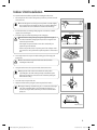
Installing the unit
fThe unit should not be installed by the user. Ask the dealer or authorized company to install the units.
fIf the unit is installed improperly, water leakage, electric shock or fire may result.
fMount with the lowest moving parts at least 2.5m (8.2 ft) above the floor or grade level. (If applicable)
fThe manufacturer does not assume responsibility for accidents or injury caused by an incorrectly installed air conditioner.
If you are unsure about installation, contact an installation specialist.
fWhen installing the built-in type air conditioner, keep all electrical cables such as the power cable and the connection
cord in pipe, ducts, cable channels e.t.c to protect them against liquids, outside impacts and so on. The air conditioner
should be used only for the applications for which it has been designed: the indoor unit is not suitable to be installed in
areas used for laundry.
fThis appliance is not accessible to the general public. This appliance should be installed according to the provided
installation instruction.
fWhen installing the air conditioner in a small room, the measure not to exceed the dangerous density is needed.
- When refrigerant leaks and exceeds the dangerous density, suffocation may occur.
fIf any gas or impurities except R410A refrigerant come into the refrigerant pipe, serious problem may occur and it may
cause injury.
fUse only rated accessories and install the air conditioner with rated equipments.
- If you dont’t use the rated accessories, the air conditioner may drop from its place, water may leak or electric shock or
fire may occur.
fVentilate your room when refrigerant gas leaks during installation.
- Toxic gas may generate when refrigerant gas contacts with heat.
fOur units must be installed in compliance with the spaces indicated in the installation manual to ensure either
accessibility from both sides or ability to perform routine maintenance and repairs. The units’ components must be
accessible and that can be disassembled in conditions of complete safety either for people or things.
For this reason, where it is not observed as indicated into the Installation Manual, the cost necessary to reach and repair
the unit (in safety, as required by current regulations in force) with slings, trucks, scaffolding or any other means of
elevation won’t be considered in-warranty and charged to end user.
3
㨰䛙GiGkptluWZ_W^hOXPUGGGZ
YWXZTWZTW]GGG㝘㤸GXWaW\aW]
Safety precautions
Power supply line or circuit breaker
fIf the power cable of this air conditioner is damaged, it must be replaced by service agent or similarly qualified persons in
order to avoid a hazard.
fThe unit must be plugged into an independent circuit if applicable or connect the power cable to the auxiliary circuit
breaker. An all pole disconnection from the power supply must be incorporated in the fixed wiring with a contact
opening of >3mm (0.12 inch).
fThe air conditioner must be installed in accordance with national wiring regulations and safety regulations wherever
applicable.
fThe electric work must be done by service agent or similarly qualified persons according to national wiring regulations
and use only rated cable.
- If the capacity of the power cable is insufficient or electric work is not properly completed, electric shock or fire may
occur.
fInstall the cables with supplied cables firmly. Fix them securely so that external force is not exerted to the terminal board.
- If the connection or fixing is incomplete, heat generation, electric shock or fire may occur.
fConnect the power cable between the indoor and outdoor unit properly so that the electrical component box cover is
not get loosen and attach the cover securely.
- If the the cover is attached incompletely, heat generation, electric shock or fire of the terminal board may occur.
CAUTION
• Make sure that you earth the cables.
- Do not connect the earth wire to the gas pipe, water pipe, lighting rod or telephone wire. If earthing is not
complete, electric shock or fire may occur.
• Install the circuit breaker.
- If the circuit breaker is not installed, electric shock or fire may occur.
• Make sure that the condensed water dripping from the drain hose runs out properly and safely.
• Install the power cable and communication cable of the indoor and outdoor unit at least 1m (3.28 ft) away from
the electric appliance.
• Install the indoor unit away from lighting apparatus using the ballast.
- If you use the wireless remote control, reception error may occur due to the ballast of the lighting apparatus.
• Do not install the air conditioner in following places.
- Place where there is mineral oil or arsenic acid. Resin parts flame and the accessories may drop or water may
leak. The capacity of the heat exchanger may reduce or the air conditioner may be out of order.
- The place where corrosive gas such as sulfurous acid gas generates from the vent pipe or air outlet. The copper
pipe or connection pipe may corrode and refrigerant may leak.
- The place where there is a machine that generates electromagnetic waves. The air conditioner may not
operate normally due to control system.
- The place where there is a danger of existing combustible gas, carbon fiber or flammable dust. The place
where thinner or gasoline is handled. Gas may leak and it may cause fire.
4
㨰䛙GiGkptluWZ_W^hOXPUGGG[
YWXZTWZTW]GGG㝘㤸GXWaW\aW]
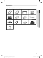
Accessories
The following accessories are supplied with the indoor unit.
The type and quantity may differ depending on the specifications.
Installation manual
Pattern sheet
Insulation cover pipe in
Insulation cover pipe out
Insulation pipe(A)
Insulation pipe(B)
Cable tie
Flexible hose
Clamp hose
Washer
Rubber
ENGLISH
User's manual
Sleeve
5
㨰䛙GiGkptluWZ_W^hOXPUGGG\
YWXZTWZTW]GGG㝘㤸GXWaW\aW^
Selecting the Installation Location
Indoor Unit
fThere must be no obstacles near the air inlet and outlet.
fInstall the indoor unit on a ceiling that can support its weight.
fMaintain sufficient clearance around the indoor unit.
fMake sure that the water dripping from the drain hose runs away correctly and safely.
fThe indoor unit must be installed in this way, that they are out of public access. (Not touchable by the users)
fAfter connecting a chamber, insulate the connection part between the indoor unit and the chamber with t10mm(3/8") or
thicker insulation. Otherwise, there can be air leak or dew from the connection part.
fRigid wall without vibration.
fWhere it is not exposed to direct sunshine.
fWhere the air filter can be removed and cleaned easily.
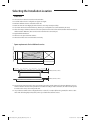
Unit Depth(D)+50mm (1.97 inch)
Space requirements for installation & service
Unit Width(W)
“A”=W+100mm(3.94 inch)
“B”=500mm(19.69 inch)
20mm(0.79 inch) or more
20mm(0.79 inch) or more
fYou must have 20mm(0.79 inch) or more space between the ceiling and the bottom of indoor unit. Otherwise, the noise
from the vibration of indoor unit may bother the user. When the ceiling is under construction, the hole for check-up must
be made to take service, clean and repair the unit.
fIt is possible to install the unit at an height of between 2.2(7.22 ft) ~ 2.5m(8.20 ft) from the ground, if the unit has a duct
with a well defined lenght[300mm(0.98 ft) or more], to avoid fan motor blower contact.
6
㨰䛙GiGkptluWZ_W^hOXPUGGG]
YWXZTWZTW]GGG㝘㤸GXWaW\aW^
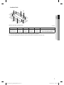
Insulation Guide
D
B
Back
Back
ENGLISH
Front
Front
A
C
Thickness: more than 10mm(0.39inch)
mm(inch)
Indoor Unit
A
B
C
D
Front/Back
1240x470x1040
(48.8x18.5x40.9)
400x190
(15.7x7.5)
1240x1040
(48.8x40.9)
470x1040
(18.5x40.9)
470x1040
(18.5x40.9)
Insulate the front and back side in proper
size at the same time when insulating the
suction duct and discharge duct.
fInsulate the end of the pipe and some curved area by using separate insulator.
fInsulate the discharge and suction part at the same time when you insulate connection duct.
7
㨰䛙GiGkptluWZ_W^hOXPUGGG^
YWXZTWZTW]GGG㝘㤸GXWaW\aW^
Selecting the Installation Location
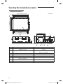
Drawing of the indoor unit
1306(51.42) Suspension position
1188(46.77) Air inlet duct flange
140X8=1120(44.09)
1040(40.94)
914 Suspension position
Unit : mm(inch)
34
470(18.50)
209(8.23) (7.87) (3.66)
236(9.29)
385(15.16)
29(1.14) 100X2=200 93 22(0.87)
660(25.98)
647(25.47)
598(23.54)
OD Ø32
35
140X8=1120(44.09)
1188(46.77) Air outlet duct flange
1240(48.82)
Discharge side
Suction side
No.
Name
Description
Liquid pipe connection
ø9.52(3/8")
Gas pipe connection
AM076✴✴✴ : ø19.05(3/4")
AM096✴✴✴ : ø22.22(7/8")
Drain pipe connection
VP25[OD ø32(1.26"), ID ø25(0.98")]
Drain pipe connection (Option drain pump)
VP25[OD ø32(1.26"), ID ø25(0.98")]
Power supply/Communication connection
Air discharge grille flange
Air suction flange
Hook
ø9.52(3/8") or M10
8
㨰䛙GiGkptluWZ_W^hOXPUGGG_
YWXZTWZTW]GGG㝘㤸GXWaW\aW`
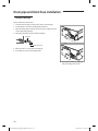
Indoor Unit Installation
It is recommended to install theY-joint before installing the indoor unit.
1. Place the pattern sheet on the ceiling at the spot where you want to install
the indoor unit.
ENGLISH
NOTE
• Since the diagram is made of paper, it may shrink or stretch slightly
due to temperature or humidity. For this reason, before drilling the
holes maintain the correct dimensions between the markings.
2. Insert bolt anchors, use existing ceiling supports or construct a suitable
support as shown in figure.
3. Install the suspension bolts depending on the ceiling type.
CAUTION
• Ensure that the ceiling is strong enough to support the weight of
the indoor unit. Before hanging the unit, test the strength of each
attached suspension bolt.
• If the length of suspension bolt is more than 1.5m(4.92ft), it is
required to prevent vibration.
• If this is not possible, create an opening on the false ceiling in order
to be able to use it to perform the required operations on the indoor
unit.
Concrete
Insert
Hole in anchor
Hole in plug
Suspension bolt(Φ9.52(3/8") or M10)
Ceiling support
4. Screw eight nuts to the suspension bolts making space for hanging the
indoor unit.
CAUTION
• You must install the suspension bolts more than four when
installing the indoor unit.
5. Hang the indoor unit to the suspension bolts between two nuts.
NOTE
• Piping must be laid and connected inside the ceiling when
suspending the unit. If the ceiling is already constructed, lay the
piping into position for connection to the unit before placing the
unit inside the ceiling.
6. Screw the nuts to suspend the unit.
7. Adjust level of the unit by using measurement plate for all 4 sides.
NOTE
• For proper drainage of condensate, give a 1° slant to the left or right
side of the unit which will be connected with the drain hose, as
shown in the figure. Make a tilt when you wish to install the drain
pump, too.
Rubber
1°
Drain hose port
9
㨰䛙GiGkptluWZ_W^hOXPUGGG`
YWXZTWZTW]GGG㝘㤸GXWaW\aW`
Purging the Unit
On delivery, the indoor unit is loaded with inert gas. All this gas must therefore be purged before connecting the assembly
piping. To purge the inert gas, proceed as follows.
Unscrew the pinch pipe at the end of each refrigerant pipe.
Wet cloth
Result : All inert gas escapes from the indoor unit.
NOTE
• To prevent dirt or foreign objects from getting into the pipes
during installation, do NOT remove the pinch pipe completely until
you are ready to connect the piping.
Liquid refrigerant
port
Gas refrigerant port
Welding flame
Connecting the Refrigerant Pipe
There are two refrigerant pipes of differing diameters:
Refrigerant oil
fA smaller one for the liquid refrigerant
fA larger one for the gas refrigerant
fThe inside of copper pipe must be clean & has no dust.
The connection procedure for the refrigerant pipes varies according to the exit
position of the pipes from the indoor unit, as seen when facing the indoor in
the “A” side.
Torque wrench
fLiquid refrigerant port
Flare nut
fGas refrigerant port
fDrain hose port
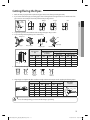
1. Remove the pinch pipe on the pipes and connect the assembly pipes to each
pipe, tightening the nuts, first manually and then with a torque wrench, a
spanner applying the following torque.
Outer diameter
mm
inch
6.35
1/4
9.52
3/8
12.7
1/2
15.88
5/8
19.05
3/4
Spanner
Union
Torque
N•m
14 ~ 18
34 ~ 42
49 ~ 61
68 ~ 82
100 ~ 120
Ibf•ft
10.3 ~ 13.3
25.1 ~ 31.0
36.1 ~ 45.0
50.2 ~ 60.5
73.8 ~ 88.5
• Must apply refrigerant oil on the flaring area to prevent a leak.
A
❋ The designs and shape are subject to
change according to the model.
NOTE
2. Be sure that there must be no crack or kink on the bended area.
10
㨰䛙GiGkptluWZ_W^hOXPUGGGXW
YWXZTWZTW]GGG㝘㤸GXWaW\aXW
Cutting/Flaring the Pipes
1. Make sure that you prepared the required tools. (pipe cutter, reamer, flaring tool and pipe holder)
2. If you want to shorten the pipe, cut it using a pipe cutter ensuring that the cut edge remains at 90° with the side of the
pipe. There are some examples of correctly and incorrectly cut edges below.
90°
Oblique
Rough
Burr
ENGLISH
Pipe
cutter
Pipe
3. To prevent a gas leak, remove all burrs at the cut edge of the pipe using a reamer.
4. Carry out flaring work using flaring tool as shown below.
A
Flaring tool
York
Die
Die
Clutch type
Wing nut type
Copper pipe
Copper pipe
Flare nut
Depth of flaring part [A]
Pipe diameter
[D]
Pipe
Flare
Using conventional flaring tool
Using flaring tool
for R-410A
Clutch type
Wing nut type
mm
inch
mm
inch
mm
inch
mm
inch
6.35
1/4
0~0.5
0~0.02
1.0~1.5
0.04~0.06
1.5~2.0
0.06~0.08
9.52
3/8
0~0.5
0~0.02
1.0~1.5
0.04~0.06
1.5~2.0
0.06~0.08
12.7
1/2
0~0.5
0~0.02
1.0~1.5
0.04~0.06
1.5~2.0
0.06~0.08
15.88
5/8
0~0.5
0~0.02
1.0~1.5
0.04~0.06
1.5~2.0
0.06~0.08
5. Check if you flared the pipe correctly. There are some examples of incorrectly flared pipes below.
Correct
Inclined
Damaged
Surface
Cracked
Uneven
Thickness
6. Align the pipes and tighten the flare nuts first manually and then with a torque wrench, applying the following torque.
Flare dimension
mm
inch
N•m
lbf.ft
mm
inch
6.35
1/4
14~18
10.3~13.3
8.7~9.1
0.34~0.36
9.52
3/8
34~42
25.1~31.0 12.8~13.2 0.50~0.52
12.7
1/2
49~61
36.1~45.0 16.2~16.6 0.64~0.65
68~82
50.2~60.5 19.3~19.7 0.76~0.78
15.88
5/8
19.05
3/4
Flare shape
mm(inch)
45° ±2°
Torque
90° ±2°
Outer diameter
R 0.4~0.8
(0.016~0.032)
100~120 73.8~88.5 23.6~24.0 0.93~0.94
• In case of needing brazing, you must work with Nitrogen gas blowing.
CAUTION
11
㨰䛙GiGkptluWZ_W^hOXPUGGGXX
YWXZTWZTW]GGG㝘㤸GXWaW\aXW
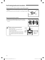
Performing leak test & insulation
Leak test
LEAK TEST WITH NITROGEN (before opening valves)
In order to detect basic refrigerant leaks, before recreating the vacuum and
recirculating the R-410A, it’s responsible of installer to pressurize the whole system
with nitrogen (using a pressure regulator) at a pressure above 4.1MPa(594.7 psig)
(gauge).
Leak check
LEAK TEST WITH R-410A (after opening valves)
Before opening valves, discharge all the nitrogen into the system and create
vacuum. After opening valves check leaks using a leak detector for refrigerant
R-410A.
• Discharge all the nitrogen to create a vacuum and charge the system.
CAUTION
Insulation
Once you have checked that there are no leaks in the system, you can insulate the piping and hose.
1. To avoid condensation problems, place T13.0 (1/2") or thicker Acrylonitrile
Butadien Rubber separately around each refrigerant pipe.
No gap
• Always make the seam of pipes face upwards.
NOTE
2. Wind insulating tape around the pipes and drain hose avoiding to compress
the insulation too much.
3. Finish wrapping insulating tape around the rest of the pipes leading to the
outdoor unit.
4. The pipes and electrical cables connecting the indoor unit with the outdoor
unit must be fixed to the wall with suitable ducts.
CAUTION
NBR
(T13.0 (1/2") or thicker)
Insulation cover pipe
Insulation pipe
Indoor unit
• All refrigerant connection must be accessible, in order to permit
either unit maintenance or removing it completely.
Be sure to overlap the
insulation
CAUTION
• Must fit tightly against
body without any gap.
12
㨰䛙GiGkptluWZ_W^hOXPUGGGXY
YWXZTWZTW]GGG㝘㤸GXWaW\aXX
5. Select the insulation of the refrigerant pipe.
fInsulate the gas side and liquid side pipe referring to the thickness according to the pipe size.
fIndoor temperature of 30°C(86˚F) and humidity of 85% is the standard condition. If install in a high humidity condition,
use one grade thicker insulator by referring to the table below.
If installing in an unfavorable conditions,use thicker one.
fInsulation’s heat-resistance temperature should be more than 120°C(248˚F).
ENGLISH
Insulation Type (Cooling, Heating)
Pipe
Outer diameter
General
[30°C(86°F), 85%]
High humidity
[30°C(86°F), over 85%]
Remarks
EPDM, NBR
Liquid
pipe
Gas pipe
mm
inch
mm
inch
mm
inch
6.35~9.52
1/4~3/8
9
3/8
9
3/8
12.7~50.80
1/2~2
13
1/2
13
1/2
6.35
1/4
13
1/2
19
3/4
9.52~25.4
3/8~1
19
3/4
25
1
28.58~44.45
1 1/8~1 3/4
19
3/4
32
1 1/4
50.8
2
25
1
38
1 1/2
Heating resisting temperature
over 120°C(248°F)
fWhen installing insulation in places and conditions below, use the same insulation that is used for high humidity
conditions.
<Geological condition>
- High humidity places such as shoreline, hot spring, near lake or river, and ridge (when the part of the building is
covered by earth and sand.)
<Operation purpose condition>
- Restaurant ceiling, sauna, swimming pool etc.
<Building construction condition>
- The ceiling frequently exposed to moisture and cooling is not covered.
e.g. The pipe installed at a corridor of a dormitory and studio or near an exit that opens and closes frequently.
- The place where the pipe is installed is highly humid due to the lack of ventilation system.
13
㨰䛙GiGkptluWZ_W^hOXPUGGGXZ
YWXZTWZTW]GGG㝘㤸GXWaW\aXX
Performing leak test & insulation
Refrigerant pipe before EEV kit and MCU or without EEV kit and MCU
fYou can contact the gas side and liquid side pipes but the pipes should not be
pressed.
fWhen contacting the gas side and gas side pipe, use 1 grade thicker insulation. Insulation
Insulation
Liquid
pipe
Gas pipe
Refrigerant pipe after EEV kit and MCU
fInstall the gas side and liquid side pipes, leave 10mm(0.39") of space.
fWhen contacting the gas side and liquid side pipe, use 1 grade thicker
insulation.
10mm(0.39") 10mm(0.39") 10mm(0.39")
Gas pipe
CAUTION
• Install the insulation not to get wider and use the
adhesives on the connection part of it to prevent
moisture from entering.
• Wind the refrigerant pipe with insulation tape if it is
exposed to outside sunlight.
• Install the refrigerant pipe respecting that the insulation
does not get thinner on the bent part or hanger of pipe.
• Add the additional insulation if the insulation plate gets
thinner.
Additional
insulation
Liquid pipe
Hanger
a
a×3
Refrigerant pipe
insulation
14
㨰䛙GiGkptluWZ_W^hOXPUGGGX[
YWXZTWZTW]GGG㝘㤸GXWaW\aXX
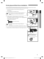
Drain pipe and drain hose installation
Care must be taken when installing the drain hose for the indoor unit to ensure that any condensate water is correctly
drained outside. The drain hose can be installed to the right or left side of the base pan.
NOTE
ENGLISH
1. Unscrew the 4 tapped screws to remove the cover of the drain hose
connection port.
2. Insert the flexible hose to the drain hose port.
• Fix the flexible hose to the indoor unit with the supplied cable
clamp securely. (Use the screwdriver to fix the flexible hose
securely.)
Drain hose connection port
3. Install the drain hose so that its length can be as short as possible.
Internal diameter of the drain hose should be the same or slightly bigger than
the external diameter of the drain hose port.
• Inner diameter of the drain hose
32mm(1.26")(inner diameter)
Cable Clamp
NOTE
• Give a slightly slant to the drain hose for proper drainage of
condensate.
• Fix the flexible hose to the PVC with the supplied cable tie securely.
4. Wrap the drain hose with the insulation drain as shown in figure and secure it.
Indoor
Unit
Cable Tie
Cable hose
Flexible hose
Insulation
CAUTION
• Must fit tightly against
body without any gap.
No gap
15
㨰䛙GiGkptluWZ_W^hOXPUGGGX\
YWXZTWZTW]GGG㝘㤸GXWaW\aXX
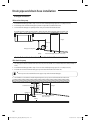
Drain pipe and drain hose installation
Drain pipe Connection
Without the drain pump
1. Install horizontal drain pipe with a slope of 1/100 or more and fix it by hanger space of 1.0~1.5m(3.29~4.92').
2. Install U-trap at the end of the drain pipe to prevent a nasty smell to reach the indoor unit.
3. Do not install the drain pipe to upward position. It may cause water flow back to the unit.
1~1.5m(3.29~4.92')
Hanger
H≥50mm(1.97")
1/2H
Drain pipe cleaning hole
Ceiling
Horizontal drain pipe more than 1/100 slope
With the drain pump
1. The drain pipe should be installed within 330mm(12.99") from the flexible hose and then lift down 20mm(0.79inch) or
more.
2. Install horizontal drain pipe with a slope of 1/100 or more and fix it by hanger space of 1.0~1.5m(3.29~4.92').
3. Install the air vent in the horizontal drain pipe to prevent water flow back to the indoor unit.
• You may not need to install it if there were proper slope in the horizontal drain pipe.
NOTE
4. The flexible hose should not be installed upward position, it may cause water flow back to the indoor unit.
Air vent
300mm(11.81") or less
Flexible hose
200mm
(7.87")or
more
20mm
(0.79")or
more
Within
330mm(12.99")
1~1.5m(3.29~4.92')
Hanger
Horizontal drainpipe more
than 1/100 slope
Ceiling
16
㨰䛙GiGkptluWZ_W^hOXPUGGGX]
YWXZTWZTW]GGG㝘㤸GXWaW\aXY
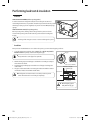
Centralized Drainage
Without the drain pump
1. Install horizontal drain pipe with a slope of 1/100 or more and fix it by hanger space of 1.0~1.5m(3.29~4.92').
2. Install U-trap at the end of the drain pipe to prevent a nasty smell to reach the indoor unit.
100mm(3.94") or more
ENGLISH
Horizontal drainpipe more than 1/100 slope
Ceiling
With the drain pump
1. Install main air vent at the front of the farthest indoor unit from the main drain when installed indoor units are more than 3.
2. You may need to install individual air vent to prevent water flow back at the top of each indoor unit drain pipe.
1~1.5m
(3.29~4.92')
Hanger
Main air vent
Individual
air vent
330mm
(12.99") or less
Main drainpipe
Centralized horizontal drain pipe
(more than 1/100 slope)
17
㨰䛙GiGkptluWZ_W^hOXPUGGGX^
YWXZTWZTW]GGG㝘㤸GXWaW\aXY
Drain pipe and drain hose installation
Testing the drainage
Prepare a little water about 2 liters.
1. Pour water into the drain pan in the indoor unit as shown in figure.
2. Confirm that the water flows out through the drain hose.
3. When the drain pump is installed, operate the unit as cooling mode and
check a drain pump pumping.
4. Check drain water drops at the end of the drain pipe.
Drainpipe
Drain pan
Drain water drops
5. Make sure there is no water leak at the drainage.
6. Reassemble the cover of water supply intake.
❋ The designs and shape are subject to
change according to the model.
18
㨰䛙GiGkptluWZ_W^hOXPUGGGX_
YWXZTWZTW]GGG㝘㤸GXWaW\aXY
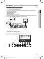
Wiring work
Power and communication cable connection
ENGLISH
1. Before wiring work, you must turn off all power source.
2. Indoor unit power should be supplied through the breaker ( ELCB or MCCB+ELB ) separated by the outdoor power.
ELCB: Earth Leakage Circuit Breaker
MCCB: Molded Case Circuit Breaker
ELB: Earth Leakage Breaker
3. The power cable should use only copper wires.
4. Connect the power cable{1(L), 2(N)} among the units within maximum length and communication cable(F1, F2) each.
5. Connect F3, F4(for communication) when installing the wired remote control.
Outdoor Unit
Wired Remote
Control
208-230V~
0&&%
(/%
or
(/&%
Indoor Unit 1
Indoor Unit 2
Indoor Unit 3
❋ ELCB : Essential Installation
Connecting power for optional product
fWhen installing optional product, make sure to follow below current capacity.
❋ Optional product is not supplied by manufacturer.
T/B
1(L)
2(N)
Vc
Vc
Vw
Vw
HOT
COIL
POWER : L
POWER : N
OPTION
VENTILATOR
AC, Below 2A
AC, Below 2A
19
㨰䛙GiGkptluWZ_W^hOXPUGGGX`
YWXZTWZTW]GGG㝘㤸GXWaW\aXZ
Wiring work
Selecting compressed ring terminal
Silver solder
mm(inch)
Norminal dimensions for cable [mm2(inch2)]
1.5 (0.002")
Norminal dimensions for screw [mm(inch)]
4 (0.15")
Standard dimension [mm(inch)]
B
4 (0.15")
4 (0.006")
4 (0.15")
4 (0.15")
6.6 (0.25") 8.0 (0.31") 6.6 (0.25") 8.5 (0.33")
Allowance [mm(inch)]
±0.2 (±0.007")
9.5 (0.37")
±0.2 (±0.007")
±0.2 (±0.007")
Standard dimension [mm(inch)]
3.4 (0.13")
4.2 (0.16")
5.6 (0.22")
Allowance [mm(inch)]
+0.3 (+0.011")
-0.2 (-0.007")
+0.3 (+0.011")
-0.2 (-0.007")
+0.3 (+0.011")
-0.2 (-0.007")
D
d1
4 (0.15")
2.5 (0.003")
Standard dimension [mm(inch)]
1.7 (0.06")
2.3 (0.09")
3.4 (0.13")
Allowance [mm(inch)]
±0.2 (±0.007")
±0.2 (±0.007")
±0.2 (±0.007")
Min. [mm(inch)]
4.1 (3/16")
6 (1/4")
6 (1/4")
E
F
Min. [mm(inch)]
6 (1/4")
6 (1/4")
6 (1/4")
L
Max. [mm(inch)]
16 (5/8")
17.5 (3/4")
20 (3/4")
Standard dimension [mm(inch)]
4.3 (0.16")
4.3 (0.16")
4.3 (0.16")
Allowance [mm(inch)]
+0.2 (+0.007")
0 (0")
+0.2 (+0.007")
0 (0")
+0.2 (+0.007")
0 (0")
Min. [mm(inch)]
0.7 (0.02")
0.8 (0.03")
0.9 (0.035")
d2
t
Specification of electronic wire
Power supply
MCCB
ELB
Power cable
Earth cable
Communication cable
Max : 242V
Min : 198V
XA
XA, 30 mA
0.1 s
2.5 mm2
(0.004 inch2)
2.5 mm2
(0.004 inch2)
0.75(0.0011 inch2)~
1.5 mm2(0.0023 inch2)
❋ Run transmission wiring between the indoor and outdoor units through a conduit to protect against external forces, and
feed the conduit through the wall together with refrigerant piping.
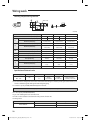
fDecide the capacity of ELCB(or MCCB+ELB) by below formula.
The capacity of ELCB(or MCCB+ELB) X[A] = 1.25 X 1.1 X ∑Ai
❋
❋
❋
❋
X : The capacity of ELCB(or MCCB+ELB).
∑Ai : Sum of Rating currents of each indoor unit.
Refer to each installation manual about the rating current of indoor unit.
Rating current
Unit
AM✴FNHDCH✴
Model
Rating current
✴✴076✴✴
3.8A
✴✴096✴✴
5.9A
20
㨰䛙GiGkptluWZ_W^hOXPUGGGYW
YWXZTWZTW]GGG㝘㤸GXWaW\aXZ
fDecide the power cable specification and maximum length within 10% power drop among indoor units.
n
Coef×35.6×LK×iK
∑(
) < 10% of input voltage[V]
1000×AK
k=1
• coef : 1.55
• LK : Distance among each indoor unit[m], AK : Power cable specification[mm2(inch2)], iK : Running current of each unit[A]
ENGLISH
Example of Installation
fTotal power cable length L = 100m(328 ft), Running current of each units 1[A]
fTotal 10 indoor units were installed.
9[A]
10[A]
1[A]
ELCB
Or MCCB+
ELB
Indoor unit 1
0[m]
10[m](32.8 ft)
Indoor unit 2
Indoor unit 10
20[m](65.62 ft)
100[m](328 ft)
fApply following equation.
n
Coef×35.6×LK×iK
∑(
) < 10% of input voltage[V]
1000×AK
k=1
❋ Calculation
• Installing with 1 sort wire.
2.5[mm2](0.004 inch2)
2.5[mm2](0.004 inch2)
-2.2[V]
220[V]
············ 2.5[mm2](0.004 inch2) ············
-2.0[V]
-(2.2+2.0+1.8+1.5+1.3+1.1+0.9+0.7+0.4+0.2)=-11.2[V]
208.8[V](Within 198V~242V)
it's okay
• Installing with 2 different sort wire.
4.0[mm2](0.006inch2)
-1.4[V]
220[V]
4.0[mm2](0.006inch2)
············ 2.5[mm2](0.004 inch2) ············
-1.2[V]
-(1.4+1.2+1.8+1.5+1.3+1.1+0.9+0.7+0.4+0.2)=-10.5[V]
209.5[V](Within 198V~242V)
it's okay
21
㨰䛙GiGkptluWZ_W^hOXPUGGGYX
YWXZTWZTW]GGG㝘㤸GXWaW\aXZ
Wiring work
CAUTION
•
•
•
•
•
•
•
•
•
•
•
•
•
•
•
•
•
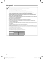
Select the power cable in accordance with relevant local and national regulations.
Wire size must comply with local and national code.
For the power cable, use the grade of H07RN-F or H05RN-F materials.
You should connect the power cable into the power cable terminal and fasten it with a clamp.
The unbalanced power must be maintained within 10% of supply rating among whole indoor units.
If the power is unbalanced greatly, it may shorten the life of the condenser. If the unbalanced power is exceeded
over 10% of supply rating, the indoor unit is protected, stopped and the error mode indicates.
To protect the product from water and possible shock, you should keep the power cable and the connection
cord of the indoor and outdoor units in the iron pipe.
Connect the power cable to the auxiliary circuit breaker. An all pole disconnection from the power supply must
be incorporated in the fixed wiring(≥3mm(1/8")).
You must keep the cable in a protection tube.
Keep distances of 50mm(2") or more between power cable and communication cable.
Maximum length of power cables are decided within 10% of power drop. If it exceeds, you must consider
another power supplying method.
The circuit breaker(ELCB or MCCB+ELB) should be considered more capacity if many indoor units are connected
from one breaker.
Use round pressure terminal for connections to the power terminal block.
For wiring, use the designated power cable and connect it firmly, then secure to prevent outside pressure being
exerted on the terminal board.
Use an appropriate screwdriver for tightening the terminal screws. A screwdriver with a small head will strip the
head and make proper tightening impossible.
Over-tightening the terminal screws may break them.
See the table below for tightening torque for the terminal screws.
M3.5
M4
Tightening torque
N•m
lbf•ft
0.8~1.0
0.59~0.74
1.2~1.5
0.89~1.1
22
㨰䛙GiGkptluWZ_W^hOXPUGGGYY
YWXZTWZTW]GGG㝘㤸GXWaW\aXZ
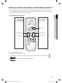
Setting an indoor unit address and installation option
fSet the indoor unit address and installation option with remote controller option. Set the each option separately since
you cannot set the ADDRESS setting and indoor unit installation setting option at the same time. You need to set twice
when setting indoor unit address and installation option.
Entering mode for
option setting
ENGLISH
The procedure of option setting
Option setting mode
Mode change
High Temp Button
High Fan Button
Low Temp Button
Low Fan Button
Step 1. Entering mode to set option
1. Remove batteries from the remote controller.
2. Insert batteries and enter the option setting mode while pressing High Temp button and Low Temp button.
3.
Check if you have entered the option setting status.
23
㨰䛙GiGkptluWZ_W^hOXPUGGGYZ
YWXZTWZTW]GGG㝘㤸GXWaW\aXZ
Setting an indoor unit address and installation option
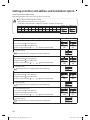
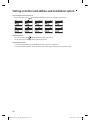
Step 2. The procedure of option setting
After entering the option setting status, select the option as listed below.
CAUTION
Option setting is available from SEG1 to SEG 24
• SEG1, SEG7, SEG13, SEG19 are not set as page option.
• Set the SEG2~SEG6, SEG8~SEG12 as ON status and SEG14~18, SEG20~24 as OFF status.
SEG1 SEG2 SEG3 SEG4 SEG5 SEG6 SEG7 SEG8 SEG9 SEG10 SEG11 SEG12
0
X
X
X
X
X
1
X
X
X
X
X
SEG13 SEG14 SEG15 SEG16 SEG17 SEG18 SEG19 SEG20 SEG21 SEG22 SEG23 SEG24
2
X
X
X
X
X
3
X
X
X
X
X
On(SEG1~12) Off(SEG13~24)
Option setting
1. Setting SEG2, SEG3 option
Press Low Fan button( ) to enter SEG2 value.
Press High Fan button( ) to enter SEG3 value.
Each time you press the button, p p … p will be selected in rotation.
Status
SEG2
SEG3
SEG4
SEG5
SEG6
SEG8
SEG9
SEG10
2. Setting Cool mode
Press Mode button to be changed to Cool mode in the ON status.
3. Setting SEG4, SEG5 option
Press Low Fan button( ) to enter SEG4 value.
Press High Fan button( ) to enter SEG5 value.
Each time you press the button, p p … p will be selected in rotation.
4. Setting Dry mode
Press Mode button to be changed to DRY mode in the ON status.
5. Setting SEG6, SEG8 option
Press Low Fan button( ) to enter SEG6 value.
Press High Fan button( ) to enter SEG8 value.
Each time you press the button, p p … p will be selected in rotation.
6. Setting Fan mode
Press Mode button to be changed to FAN mode in the ON status.
7. Setting SEG9, SEG10 option
Press Low Fan button( ) to enter SEG9 value.
Press High Fan button( ) to enter SEG10 value.
Each time you press the button, p p … p will be selected in rotation.
8. Setting Heat mode
Press Mode button to be changed to HEAT mode in the ON status.
24
㨰䛙GiGkptluWZ_W^hOXPUGGGY[
YWXZTWZTW]GGG㝘㤸GXWaW\aX\
Option setting
9. Setting SEG11, SEG12 option
Press Low Fan button( ) to enter SEG11 value.
Press High Fan button( ) to enter SEG12 value.
Each time you press the button, p p … p will be selected in rotation.
Status
SEG12
SEG14
SEG15
SEG16
SEG17
SEG18
SEG20
SEG21
SEG22
SEG23
SEG24
ENGLISH
SEG11
10. Setting Auto mode
Press Mode button to be changed to AUTO mode in the OFF status.
11. Setting SEG14, SEG15 option
Press Low Fan button( ) to enter SEG14 value.
Press High Fan button( ) to enter SEG15 value.
Each time you press the button, p p … p will be selected in rotation.
12. Setting Cool mode
Press Mode button to be change to Cool mode in the OFF status.
13. Setting SEG16, SEG17 option
Press Low Fan button( ) to enter SEG16 value.
Press High Fan button( ) to enter SEG17 value.
Each time you press the button, p p … p will be selected in rotation.
14. Setting Dry mode
Press Mode button to be change to Dry mode in the OFF status.
15. Setting SEG18, SEG20 option
Press Low Fan button( ) to enter SEG18 value.
Press High Fan button( ) to enter SEG20 value.
Each time you press the button, p p … p will be selected in rotation.
16. Setting Fan mode
Press Mode button to be change to Fan mode in the OFF status.
17. Setting SEG21, SEG22 option
Press Low Fan button( ) to enter SEG21 value.
Press High Fan button( ) to enter SEG22 value.
Each time you press the button, p p … p will be selected in rotation.
18. Setting Heat mode
Press Mode button to be change to HEAT mode in the OFF status.
19. Setting SEG23, SEG24 mode
Press Low Fan button( ) to enter SEG23 value.
Press High Fan button( ) to enter SEG24 value.
Each time you press the button, p p … p will be selected in rotation.
25
㨰䛙GiGkptluWZ_W^hOXPUGGGY\
YWXZTWZTW]GGG㝘㤸GXWaW\aX_
Setting an indoor unit address and installation option
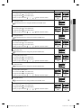
Step 3. Check the option you have set
After setting option, press
button to check whether the option code you input is correct or not.
¤
¤
¤
¤
¤
¤
¤
¤
¤
Step 4. Input option
Press the operation button
with the direction of remote control for set.
For the correct option setting, you must input the option twice.
Step 5. Check operation
1) Reset the indoor unit by pressing the RESET button of indoor unit or outdoor unit.
2) Take the batteries out of the remote controller and insert them again and then press the operation button.
26
㨰䛙GiGkptluWZ_W^hOXPUGGGY]
YWXZTWZTW]GGG㝘㤸GXWaW\aX_
Setting an indoor unit address (MAIN/RMC)
1. Check whether power is supplied or not.
- When the indoor unit is not plugged in, there should be additional
power supply in the indoor unit.
2. The panel(display) should be connected to an indoor unit to receive
option.
3. Before installing the indoor unit, assign an address to the indoor unit
according to the air conditioning system plan.
4. Assign an indoor unit address by wireless remote controller.
- The initial setting status of indoor unit ADDRESS(MAIN/RMC) is
“0A0000-100000-200000-300000”.
Indoor Unit
1(L)
2(N)
ENGLISH
F2
F1
Option No. : 0AXXXX-1XXXXX-2XXXXX-3XXXXX
Option
SEG1
Explanation
SEG2
PAGE
MODE
SEG3
SEG4
SEG5
SEG6
100-digit of indoor unit
Setting Main address
10-digit of indoor unit
address
The unit digit of an
indoor unit
Remote
Controller
Display
Indication
Details
Indication
Details
Indication
Details
No Main
address
Main
address
1
setting
mode
SEG9
Indication
Details
Indication
Details
Indication
Details
0~9
100
-digit
0~9
10-digit
0~9
A unit digit
0
Indication
and Details
0
A
Option
SEG7
SEG8
Explanation
PAGE
SEG10
Setting RMC address
SEG11
SEG12
Group channel(*16)
Group address
Remote
Controller
Display
Indication
Details
-
Indication
0
Indication
and Details
1
1
CAUTION
Details
No RMC
address
RMC
address
setting
mode
-
Indication
Details
Indication
Details
RMC1
0~F
RMC2
0~F
• When “A”~”F” is entered to SEG5~6, the indoor unit MAIN ADDRESS is not changed.
• If you set the SEG 3 as 0, the indoor unit will maintain the previous MAIN ADDRESS even if you input the option
value of SEG5~6.
• If you set the SEG 9 as 0, the indoor unit will maintain previous RMC ADDRESS even if you input the option value
of SEG11~12.
• You cannot set SEG11 and SEG12 as F value at the same time.
27
㨰䛙GiGkptluWZ_W^hOXPUGGGY^
YWXZTWZTW]GGG㝘㤸GXWaW\aX`
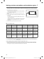
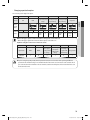
Setting an indoor unit address and installation option
Setting an indoor unit installation option (suitable for the condition of each installation location)
1. Check whether power is supplied or not.
- When the indoor unit is not plugged in, there should be additional
power supply in the indoor unit.
2. The panel(display) should be connected to an indoor unit to receive
option.
3. Set the installation option according to the installation condition of an
air conditioner.
- The default setting of an indoor unit installation option is “020010100000- 200000-300000”.
- Individual control of a remote controller(SEG20) is the function that
controls an indoor unit individually when there is more than one
indoor unit.
4. Set the indoor unit option by wireless remote controller.
Indoor Unit
1(L)
2(N)
F2
F1
■ 02 series installation option
SEG1
SEG2
SEG3
SEG4
SEG5
SEG6
0
1
-
External room
temperature sensor
Central control
FAN RPM
compensation
SEG7
SEG8
SEG9
SEG10
SEG11
SEG12
1
Drain pump
Hot water heater
-
EEV Step when
heating stops
Master / Slave
SEG13
SEG14
SEG15
SEG16
SEG17
SEG18
2
External control
External control
output
S-Plasma ion
Buzzer
Number of hours
using filter
SEG19
SEG20
SE21
SEG22
SEG23
SEG24
3
Individual control of
a remote controller
Heating setting
compensation
EEV Step of stopped
unit during oil
return/defrost mode
Motion detect
sensor
-
f1WAY/2WAY/4WAY MODEL : Drain pump(SEG8) will be set to ‘USE + 3minute delay’ even if the drain pump is set to 0.
f1WAY/2WAY/4WAY, DUCT MODEL : Number of hours using filter(SEG18) will be set to ‘1000hour’ even if the SEG18 is set
to exept for 2 or 6.
fWhen setting the option other than above SEG values, the option will be set as “0”.
fSEG5 central control option is basically set as 1(Use), so you don’t need to set the central control option additionally.
However, if the central control is not connected but it doesn’t indicate an error message, you need to set the central
control option as 0 (Disuse) to exclude the indoor unit from the central control.
28
㨰䛙GiGkptluWZ_W^hOXPUGGGY_
YWXZTWZTW]GGG㝘㤸GXWaW\aX`
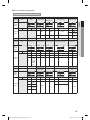
■ 02 series installation option(Detailed)
Option No. : 02XXXX-1XXXXX-2XXXXX-3XXXXX
Option
SEG1
SEG2
SEG3
Explanation
PAGE
MODE
Use of robot cleaning
SEG4
Use of external room
temperature sensor
SEG5
SEG6
Use of central control
FAN RPM compensation
ENGLISH
Remote
Controller
Display
Indication
Indication and
Details
Details
Indication
0
Details
Indication
Details
Indication
Details
Indication
Details
0
Disuse
0
Disuse
0
Disuse
1
Use
1
Use
1
Use
2
Option
SEG7
SEG8
Explanation
PAGE
Use of drain pump
SEG9
SEG10
Indication
0
1
2
SEG11
Use of hot water heater Use of electronic heater
EEV Step when heating stops
Details
Disuse
RPM
compensation
High ceiling
KIT
SEG12
Master / Slave
Remote
Controller
Display
Indication
Details
Indication and
Details
1
Option
SEG13
Explanation
PAGE
Indication
0
1
Details Indication Details Indication Details
Disuse
0
Disuse
0
Disuse
Use
1
Use
1
Use
When an
indoor unit
stops, drain
2
pump will
operate for
3min
SEG14
SEG15
SEG16
Setting the output of
Use of external control
S-Plasma ion
external control
Indication
Details
Indication
0
Default value
0
1
Noise decreasing setting
1
SEG17
Buzzer control
Details
slave
master
SEG18
Number of hours using
filter
Remote
Controller
Display
Indication
Details
Indication
0
1
Indication and
Details
2
2
3
Details Indication Details Indication
Disuse
0
Thermo on
0
ON/OFF
control
OFF control
Operation
Window ON/
1
1
on
OFF control
Details
Disuse
Use
Indication
0
Details
Use buzzer
1
Disuse buzzer
Indication Details
2
1000 Hour
6
2000 Hour
29
㨰䛙GiGkptluWZ_W^hOXPUGGGY`
YWXZTWZTW]GGG㝘㤸GXWaW\aYW
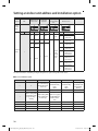
Setting an indoor unit address and installation option
Option
SEG19
SEG20
SEG21
Explanation
PAGE
Individual control of a
remote controller
Heating setting
compensation
SEG22
EEV Step of stopped unit
during oil return/defrost
mode
SEG23
SEG24
Motion detect sensor
-
Remote
Controller
Display
Indication
Details
Indication
Details
Indication
Details
Indication
Details
0 or 1
channel 1
0
Disuse
0
Default
value
2
channel 2
1
2°C(35.6°F)
3
channel 3
Indication
0
1
2
3
4
Indication and
Details
3
1
2
4
5°C(41°F)
channel 4
Oil return
or Noise
decreasing
in defrost
mode
5
6
7
8
Details
Disuse
Turn out in 30min.
without motion
Turn out in 60min.
without motion
Turn out in 120min.
without motion
Turn out in 180min.
without motion
Turn out in 30min.
without motion or
*advanced function
Turn out in 60min.
without motion or
*advanced function
Turn out in 120min.
without motion or
*advanced function
Turn out in 180min.
without motion or
*advanced function
❋ Advanced function: Controlling cooling/heating current or power saving with motion detect.
■ 05 series installation option
SEG1
SEG2
0
5
SEG7
SEG8
1
SEG13
SEG3
SEG4
SEG9
SEG10
Compensation
(When setting SEG3)
(When setting SEG3) option for Long pipe
Standard for mode
Time required for or height difference
change Cooling →
mode change
between indoor
Heating
units
SEG14
SEG5
SEG6
(When setting SEG3) (When setting SEG3) (When setting SEG3)
Use of Auto Change
Standard heating
Standard cooling
Standard for mode
Over for HR only in
temp.
temp.
change Heating →
Auto mode
Offset
Offset
Cooling
SEG15
SEG16
SEG11
SEG12
-
-
SEG17
SEG18
2
-
-
-
-
-
SEG19
SEG20
SEG21
SEG22
SEG23
SEG24
3
-
-
-
-
-
30
㨰䛙GiGkptluWZ_W^hOXPUGGGZW
YWXZTWZTW]GGG㝘㤸GXWaW\aYW
■ 05 series installation option(Detailed)
Option No. : 05XXXX-1XXXXX-2XXXXX-3XXXXX
Option
SEG1
SEG2
Explanation
PAGE
MODE
SEG3
SEG5
(When setting SEG3)
Standard cooling temp. Offset
SEG6
(When setting SEG3)
Standard for mode change
Heating → Cooling
Remote
Controller
Display
Indication
Details
Indication
Details
Indication
0
Indication and
Details
0
5
Use Auto
Change Over
for HR only
1
Option
Explanation
SEG7
PAGE
SEG8
(When setting SEG3)
Standard for mode
changing Cooling →
Heating mode
Details
Follow
product
option
Indication
Details
Indication
Details
Indication
Details
0
0
0
0
0
1
1
2
3
4
5
6
7
0.5
1
1.5
2
2.5
3
3.5
1
2
3
4
5
6
7
0.5
1
1.5
2
2.5
3
3.5
1
2
3
4
5
6
7
1.5
2
2.5
3
3.5
4
4.5
SEG9
SEG10
SEG11
ENGLISH
SEG4
(When setting SEG3)
Use of Auto Change Over
for HR only in Auto mode Standard heating temp.
Offset
SEG12
(When setting SEG3) Compensation option
for Long pipe or height
Time required for mode diffference between
change
indoor units
Remote
Controller
Display
Indication
Indication and
Details
Details
Indication
Details
Indication
Details
Indication
0
0
1
0
5 min.
1
2
1.5
2
1
2
7 min.
9 min.
3
2.5
3
11 min.
4
5
6
3
3.5
4
4
5
6
13 min.
15 min.
20 min.
7
4.5
7
30 min.
1
1
2
Details
Use default
value
1) Height
difference1)
is more than
30m or
2) Distance2)
is longer than
110m
1) Height
difference1) is
15~30m or
2) Distance2) is
50~110m
1)
Height difference : The difference of the height between the corresponding indoor uint and the indoor unit installed at the
lowest place.
For example, When the indoor unit is installed 40m(131.23 ft) higher than the indoor unit installed at the
lowest place, select the option "1".
2)
Distance : The difference between the pipe length of the indoor unit istalled at farthest place from an outdoor unit and the
pipe length of the corresponding indoor unit from an outdoor unit.
For example, when the farthest pipe length is 100m(328 ft) and the corresponding indoor unit is 40m(131.23 ft)
away from an outdoor unit, select the option "2". (100m(328 ft) - 40m(131.23 ft) = 60m(196.85 ft))
31
㨰䛙GiGkptluWZ_W^hOXPUGGGZX
YWXZTWZTW]GGG㝘㤸GXWaW\aYX
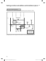
Setting an indoor unit address and installation option
SEG 3, 4, 5, 6, 8, 9 additional information
Heating Thermo On
Heating Thermo Off
Cooling Thermo On
Cooling Thermo Off
When the SEG 3 is set as "1" and follow Auto Change Over for HR only operation, it will operate as follows.
Standard temp. for
Heating → Cooling
Temp.
c
b
Standard temp. for
Cooling
B
C
Ts
A
Set temp. for
Auto mode
D
a
Standard temp. for
Heating
d
Standard temp.
for Cooling →
Heating
A : Set with SEG4(˚C)
B : Set with SEG5(˚C)
C : Set with SEG6(˚C)
D : Set with SEG8(˚C)
Cooling/Heating mode can be changed when Thermo Off status is maintained during the time with SEG9.
32
㨰䛙GiGkptluWZ_W^hOXPUGGGZY
YWXZTWZTW]GGG㝘㤸GXWaW\aYX
Changing a particular option
You can change each digit of set option.
Option
SEG1
SEG2
Explanation
PAGE
MODE
SEG3
SEG4
SEG5
SEG6
The option mode you want The tens’ digit of an option The unit digit of an option
to change
SEG you will change
SEG you will change
Changed value
ENGLISH
Remote
Controller
Display
Indication
Indication and
Details
NOTE
Details
0
Details
Indication
Details
Indication
Details
Indication
Details
Option
mode
1~6
Tens’ digit
of SEG
0~9
Unit digit
of SEG
0~9
D
Indication
The
changed
value
Details
0~F
• When changing a digit of an indoor unit address setting option, set the SEG3 as ‘A’.
• When changing a digit of indoor unit installation option, set the SEG3 as ‘2’.
Ex) When setting the ‘buzzer control’ into disuse status.
Option
CAUTION
Indication
SEG1
SEG2
SEG3
Explanation
PAGE
MODE
The option
mode you want
to change
Indication
0
D
2
SEG4
SEG5
SEG6
The tens’ digit
The unit digit of
of an option
an option SEG Changed value
SEG you will
you will change
change
1
7
1
• If you are using heat pump model, mixed operation mode (two or more indoor units operating in different
operation mode simultaneously) is not available when the indoor units are connected to same outdoor unit. If
you set the master indoor unit with a remote controller, outdoor unit will operate in the mode which was set in
the master indoor unit.
33
㨰䛙GiGkptluWZ_W^hOXPUGGGZZ
YWXZTWZTW]GGG㝘㤸GXWaW\aYX
Final Checks and User Tips
To complete the installation, perform the following checks and tests to ensure that the air conditioner operates correctly.
1. Check the followings.
fStrength of the installation site
fTightness of pipe connection to detect a gas leak
fElectric wiring connections
fHeat-resistant insulation of the pipe
fDrainage
fEarth conductor connection
fCorrect operation (follow the steps below)
After finishing the installation of the air conditioner, you should explain the following to the user. Refer to appropriate pages
in the User’s Manual.
1. How to start and stop the air conditioner
2. How to select the modes and functions
3. How to adjust the temperature and fan speed
4. How to adjust the airflow direction
5. How to set the timers
6. How to clean and replace the filters
NOTE
• When you complete the installation successfully, hand over the User’s Manual and this Installation Manual to the
user for storage in a handy and safe place.
34
㨰䛙GiGkptluWZ_W^hOXPUGGGZ[
YWXZTWZTW]GGG㝘㤸GXWaW\aYY
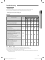
Troubleshooting
Detection of errors
ENGLISH
fIf an error occurs during the operation, an LED flickers and the operation is stopped except the LED.
fIf you re-operate the air conditioner, it operates normally at first, then detect an error again.
LED Display on the receiver & display unit
LED Display
LED Display
Abnormal conditions
Error
code
Error on indoor temperature sensor (Short or Open)
E121
1. Error on Eva-in sensor (Short or Open)
2. Error on Eva-out sensor (Short or Open)
3. Discharge sensor error (Short or Open)
E122
E123
E126
Indoor fan error
E154
1. Error on outdoor temperature sensor (Short or Open)
2. Error on cond sensor
3. Error on discharge sensor
Other outdoor unit sensor error that is not on the above list
E221
E237
E251
1. When there is no communication between the
indoor∙outdoor units for 2 minutes
2. Communication error received from the outdoor unit
3. 3 miniute tracking error on outdoor unit
4. Communication error after tracking due to unmatching
number of installed units
5. Error due to repeated communication address
6. Communication address not confirmed
Other outdoor unit communication error that is not on the
above list
E101
Self diagnosis error display
1. Error due to opened EEV (2nd detection)
2. Error due to closed EEV (2nd detection)
3. Eva in sensor is detached
4. Eva out sensor is detached
5. Thermal fuse error (Open)
E102
E202
E201
E108
E109
E151
E152
E128
E129
E198
● On
Flickering
Off
fIf you turn off the air conditioner when the LED is flickering, the LED is also turned off.
fIf you re-operate the air conditioner, it operates normally at first, then detect an error again.
fWhen E108 error occurs, change the address and reset the system.
Ex.) When address of the indoor unit #1 and #2 are set as 5, address of the indoor unit #1 will become 5 and indoor unit
#2 will display E108, A002.
35
㨰䛙GiGkptluWZ_W^hOXPUGGGZ\
YWXZTWZTW]GGG㝘㤸GXWaW\aYY
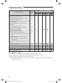
Troubleshooting
LED Display
Abnormal conditions
Error
code
1. COND mid sensor is detached
2. Refrigerant leakage (2nd detection)
3. Abnomally high temperature on Cond (2nd detection)
4. Low pressure s/w (2nd detection)
5. Abnomally high temperature on discharged air on outdoor
unit (2nd detection)
6. Indoor operation stop due to unconfirmed error on
outdoor unit
7. Error due to reverse phase detection
8. Comp stop due to freeze detection (6th detection)
9. High pressure sensor is detached
10. Low pressure sensor is detached
11. Outdoor unit copression ration error
12. Outdoor sump down_1 prevetion control
13. Compressor down due to low pressure sensor prevention
control_1
14. Simultaneous opening of cooling/heating MCU SOL
valve (1st detection)
15. Simultaneous opening of cooling/heating MCU SOL
valve (2nd detection)
Other outdoor unit self-diagnosis error that is not on the
above list
E241
E554
E450
E451
E416
Flowating s/w (2nd detection)
E153
EEPROM error
E162
EEPROM option error
E163
Error due to incompatible indoor unit
E164
E559
E425
E403
E301
E306
E428
E413
E410
E180
E181
● On
Flickering
Off
fIf you turn off the air conditioner when the LED is flickering, the LED is also turned off.
fIf you re-operate the air conditioner, it operates normally at first, then detect an error again.
fWhen E108 error occurs, change the address and reset the system.
Ex.) When address of the indoor unit #1 and #2 are set as 5, address of the indoor unit #1 will become 5 and indoor unit
#2 will display E108, A002.
36
㨰䛙GiGkptluWZ_W^hOXPUGGGZ]
YWXZTWZTW]GGG㝘㤸GXWaW\aYY
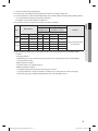
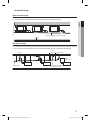
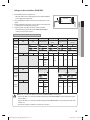
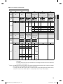
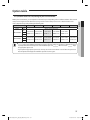
Option table
E.S.P(External Static Pressure)setting for phase control motor
Static Pressure(mmAq)
Model
Step
AM076FNHDCH
MID
5
10
15
20
25
28
ENGLISH
With its phase control motor, you can adjust the indoor unit fan speed depending on the installation condition. If the external
static pressure is high so that the duct becomes longer or if the external static pressure is low so that the duct becomes
shorter, adjust the fan speed by referring the following table.
Option code for indoor unit
HI
011054-195097- 011054-1950C7- 011054-1950E8- 011054-19544D- 011054-19549F20DCDC-331110 20DCDC-331110 20DCDC-331110 20DCDC-331110 20DCDC-331110
-
LOW
HI
AM096FNHDCH
MID
011054-195407- 011054-195429- 011054-19545B- 011054-19549E- 011054-1955D1- 011054-1955F3231C1C-331110 231C1C-331110 231C1C-331110 231C1C-331110 231C1C-331110 231C1C-331110
LOW
•
NOTE
represents E.S.P(External Static Pressure)range of factory setting. You don’t have to adjust the fan speed
. When it is out of
, input
separately if the external static pressure of the installation place is in
the appropriate option code.
• If you input the inappropriate option code, error may occur or the air conditioner is out of order. The option code
must be inputted correctly by the installation specialist or service agent.
37
㨰䛙GiGkptluWZ_W^hOXPUGGGZ^
YWXZTWZTW]GGG㝘㤸GXWaW\aYY