1
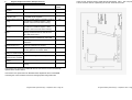
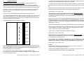
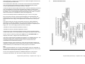
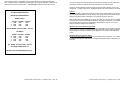
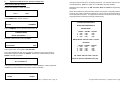
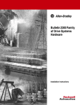
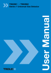
Codax
™
Codax Installation & Service Manual
(Instructions for Cabled & Cable-less Installation/Mode)
Installing Engineer will need to refer to the Codax
Owner-Operator Manual for full set-up and operating instructions
Programmable Systems Design – September 2004 - Page 1
Introduction
Programmable Systems Design – September 2004 - Page 2
Codax™
is a customer access control system for use by retailers in a retail
environment and in many other situations where access needs to be controlled. Codax
has endless applications and is suitable for use where coins, token or cards have
traditionally been used for access and making retail sales.
NOTES
Codax Ultra, Codax Retro and Codax Customised Systems
Codax is often manufactured and or programmed to have specific features for specific
clients, therefore some functions and operations may not be available or may be
operated slightly differently within the system software of your chosen
system/installation. Check with your installer. Text prompts will always guide you
through the system menus.
Codax™
is designed and manufactured by Programmable Systems Design
Limited, Bristol, England BS48 1JJ.
www.psdcodax.com
Codax software copyright, when you purchase each single Codax system you are
granted a single licence to operate the one version of the operating system supplied
with the hardware. No permission is granted to make copies of this software. Software
changes or upgrades are supplied within a replaceable EPROM microchip, again a
single licence is granted with each original EPROM produced by PSD. Copying of
software from theses EPROM’s is not authorised. Do not purchase or operate illegal
versions of Codax software.
© 2004 Programmable Systems Design Ltd – All Rights Reserved
.
Index to Installation and Service Manual
Programmable Systems Design – September 2004 - Page 26
Programmable Systems Design – September 2004 - Page 3
The cover plate has a foam rubber strip on three sides only - make sure that the side
without the strip is at the bottom to allow water to drain out freely.
Contents:
Page
Important Safety Instructions
System Overview
Installation Guidance
Fault Codes
System Cold Start & Access Terminal Configuration
Engineer Diagnostics
Engineer Service and Repair Guide
Engineer Replacement parts
Utilising an Existing Card Reader Housing
5
6
8
13
14
19
20
22
24
Codax Access Unit – Cut-out & fixing holes
Allow 15mm clearance all around the mounting cut-out for fitting the front cover.
Allow for 80mm clearance rear of panel projection.
Allow 40mm minimum clearance at bottom for cable exit and cable glands.
A = 4 holes 4.2 diam
A
A
90
122
A
A
130
140
1.
Important Safety Information
Programmable Systems Design – September 2004 - Page 4
Programmable Systems Design – September 2004 - Page 25
9
Utilising Existing Card Reader Housing/Box
In most cases, it is possible to mount the Codax Access Unit into the OEM card
reader box by utilising our standard mounting bracket and cover plate. The below
mounting instructions will allow easy access to the Codax Access Unit for servicing.
With some card reader units it is better for the customer if the existing face of the
box is turned to face the car wash and the Codax Access Unit is installed on the
clear side of the box.
Prior to installing or operating this equipment, please read this Important Safety
Information carefully,
•
Codax must only be installed or serviced by a competent person who has sufficient
electrical and product service knowledge. End users/owners must not attempt any
service operations or remove any covers.
•
The only end user serviceable components are replacement ticket rolls and
replacement printer ribbons (refer to end user instruction manual).
•
The person responsible for installing or commissioning Codax must ensure that the
Operating Manuals are presented to the owner/operator of the system.
•
The components of the system, ticket issue terminal and machine access terminal
must only be powered by a Codax 24 volt DC power supply. The Codax
communication cables, the Codax system or any component of the Codax system
must not be powered, connected too, or installed in such a way that voltage from
any external source is allowed or could be allowed to pass through the system.
Failure to carefully follow these instructions, may lead to fatal accidents from
electric shock and damage to the Codax system.
Decide on the best location for the Access Unit to be positioned. Consideration must
be given to components already mounted within the box, accessibility for service of
all components. Ensure the display should is easily visible to the client using the
wash/machine.
•
The CE certificate applying to Codax relates to Codax as a standalone system. It
is the responsibility of the installer and or equipment manufacturer to ensure that
the integrity of Codax or the equipment, especially the electrical integrity, is not
affected or compromised in any way.
Provide an accurate cut-out and mounting holes according to the drawing shown
over the page.
•
CE Compliance: Codax and its original components are manufactured to observe
the EC EMC legislation and safety standards. Programmable Systems Design Ltd
cannot guarantee that the product/system will continue to observe these
regulations when installed onto other equipment and or used with non-original
equipment and/or cabling, this is the responsibility of the installer and/or equipment
manufacturer.
•
The Codax power supply units must be installed in a dry environment and only
connected to an electrical supply that has been installed by a qualified electrician.
•
The Codax Ticket Issue Terminal is designed to be installed and operated indoors.
Do not allow fluids to enter or to be splashed onto it.
•
Codax is not designed to be installed or operated in hazardous areas.
If there is a need to cover an existing aperture (position of existing coin mechanism
etc) then a standard universal mounting plate is available. This plate has the
necessary cut-outs ready for the Access Unit mounting bracket. We also have
available a range of OEM card reader housing/box, replacement front plates. We
can also quote to supply any type when reasonable quantities are required.
If difficulty is encountered when fitting the Access Unit to the existing OEM card
reader housing/box or if this is for a new installation consideration should be given to
utilising a Codax Access Unit Housing and Bi-directional Pedestal.
Mounting the Access Unit
The unit should be mounted at a height appropriate for entering the code and
reading the display.
The unit should be mounted vertically (not at an angle). This allows water to drain
freely from the face of the unit, avoids rain getting into the unit if the cover is
removed for maintenance purposes, and this also avoids possible overheating
problems if the overhead sun is allowed to shine through the display window at right
angles.
The cable glands on the unit should be facing down to avoid the ingress of water
and should be double sealed with silicon rubber after assembly and wiring is
complete.
The plastic enclosure box of the Access unit is mounted onto the mounting bracket
using the 4 plastite self- tapping screws supplied.
Make sure that the mounting bracket is properly earthed. Use an earth strap if the
surface on which it is mounted is not metal or not already earthed. The mounting
bracket is fixed using the screws and tower nuts supplied. The tower nuts are
tightened in place and then ready to accept the four hexagon headed screws which
hold the cover plate.
Programmable Systems Design – September 2004 - Page 24
Programmable Systems Design – September 2004 - Page 5
2.
System Overview
The PSD Codax system generally consists of items from the following component list
and will depend on the clients purchase order instructions. Always check customer
instructions and packing note to determine the components required:
Note:
There are two basic methods to install a Codax system. They are Cabled (Codax Ultra)
or Cable-less (Codax Retro). Cabled mode requires the installation of a
communications cable between the Machine/service Codax Access Terminal and a
Codax Distribution Unit. Please refer to Codax sales information to identify the features
available according to the desired installation mode. In cable-less mode certain
features and functions will not be available.
1
2
3
4
5
6
7
(CTT)
(CTTS)
(DU)
(PS)
(CAT)
(PSA)
(INK)
Codax Genuine Paper Rolls
Codax Ticket Rolls &
Ribbons
Pack consisting of 20 yellow paper rolls and 4 genuine
Epsom printer ribbons.
Caution:
Always ensure that Codax yellow paper is used. Codax yellow tickets will help
your customers’ to easily identify their Access Ticket; thus preventing
problems/queuing at the machine/service.
Use of low grade paper rolls will cause paper dust to damage your printer unit
Codax Ticket Terminal
Codax Ticket Terminal Slave Unit (Optional)
CTT Distribution Unit & Power supply (Cabled installations)
CTT Power Supply Unit (Cable-less installations)
Codax Access Terminal (one unit per machine/service)
CAT Power supply (Optional for certain machine types)
CAT Interface & Installation kit (Machine specific)
(Includes standard Access Terminal mounting plate).
8
9
Machine specific, card reader replacement front plate (Optional)
Point of Sale Link Kits
Optional, Customer Machine Interface Unit
10
(APT)
Codax Access Unit Housing & Bi-directional pedestal.
(Items 5, 6 & 7 can be pre-mounted within this unit)
The Codax Ticket Terminal (CTT) is normally situated on the kiosk sales desk
convenient for the operator/sales person. Adequate space should be allowed behind to
allow cable access and for opening of the rear cover.
The Codax Distribution and Power Supply Unit (CDU) (only required for cabled
installations) is designed to be wall mounted using the brackets supplied. The unit
should not be covered as overheating could occur . The unit requires 240 Volt AC
electric supply fused at 5 amps; it also receives the cable connections from the Codax
Ticket Terminal, Point of Sale Terminal and the Access Terminal/s, hence when
positioning the unit consideration should be given to this. This unit provides a 24-volt
power supply to the CTT. A Standard 5 metre connection lead is supplied for
connecting this unit to the Codax Ticket Terminal
The Codax Power Supply Unit (only required for cable-less installations) provides a 24volt DC power supply to the CTT, it should therefore be located in a suitable and
convenient location close to the CTT. A Standard 5 metre connection lead is supplied
for connecting this unit to the Codax Ticket Terminal.
The Codax Access Terminal (CAT) is fitted at the machine/car wash where the token
mechanism/card reader would normally be. If it is to be installed onto an existing
machine, it can mounted onto a replacement front panel for the existing card
reader/machine front. Refer to section 9 for suggested mounting instructions.
For cabled installations, the CAT is linked to the Distribution Unit at the sales point via a
4-core screened cable. Specification details of this cable are given later.
Programmable Systems Design – September 2004 - Page 6
Programmable Systems Design – September 2004 - Page 23
8
Engineer Replacement Parts & Repair Services
Codax Access Terminal Housing and Bi-directional Pedestal. (APT). This unit provides
a smart and clear method of presenting the Access Terminal to the user.
Part Description
Notes
Repair service
Available
Ticket Issue Unit.
Complete
Excludes Memory Module Board.
Yes
Access Unit Complete
Excludes Memory EPROM
Yes
Ultra Power Supply &
Distribution Unit
Used for Cabled Installation. Can also be used
for unstable electric supplies.
Yes
Machine Interface Module Interface module used for connecting Codax to
- 6 way
the machine’s controller/computer. State
machine make and model when ordering
Yes
Machine Interface Module Interface module used for connecting Codax to
- 16 way
the machine’s controller/computer. State
machine’s make and model when ordering.
Yes
Ticket Issue Unit Memory Need to quote existing software version when
Board
ordering. Remember this unit has all of the
site’s data stored onto it.
No
Access Unit EPROM
Need to quote existing software version when
ordering, machine manufacturer and model.
No
Power Supply Unit Retro
Power supply for Ticket Issue Unit, cable-less
installations.
No
Power Supply Unit for
Machine Access Unit
Used for cable-less installations when 24v
supply not available from machine.
No
Printer Assembly
Printer and paper cutter supplied complete with
mounting plate and connection leads.
No
Keypad Assembly & Text Complete assembly for on-site replacement.
Display for Ticket Terminal
No
Keypad & Text Display for Complete assembly for on-site replacement.
Machine Access Terminal
No
Codax Access Terminal
Housing
Codax Pedestal
Replacement Housing and Front Plate
No
Bi-directional Pedestal for Access Terminal
Housing
No
Units returned for repair with an EPROM will have the software version automatically
updated to the current version.
Units returned for repair without an EPROM will be dispatched with a new EPROM
containing the current software version and the appropriate charge will made.
Programmable Systems Design – September 2004 - Page 22
Programmable Systems Design – September 2004 - Page 7
3.
Installation Guidance
The Ticket Issue Terminal keypad is replaced as an assembly consisting of the keypad
membrane, the text display and the lid of the Ticket Terminal.
Distribution and Power Supply Unit Installation (Cabled installations only)
The Distribution Unit can be mounted horizontally or on a wall using the brackets
supplied. If wall mounting is desired, the brackets can be found screwed to the sides of
the unit; the brackets have to be turned around to allow access to the mounting holes.
The cable connector cover is held in place by 2 nylon thumb screws, once these are
removed the cover can be hinged back to reveal the connectors and the cable
anchoring bracket.
Remove the cable anchoring bracket by unscrewing the pillars securing it.
The cables can be attached to the bracket and wired to the appropriate connector plugs
away from the Distribution Unit. The cables should be attached to the bracket using
cable ties. The cable ends should protrude from the bracket through a corresponding
hole that is adjacent to the plug socket.
The diagram below shows the connectors functions.
POS
CTT
CAT 1
Lift the lid of the unit and remove the memory module cover plate by removing the three
white plastic screws. Remove the nut and washer securing the earth wire to the Codax
lid.
Unplug the keypad and display ribbon cables from the circuit board. Close the Codax
lid and remove the two lid hinge screws. Lift the Keypad Assembly clear.
Reassembly is in the reverse order.
Removing and or replacing the Codax Access Terminal ‘Keypad Assembly’.
Should the Keypad become damaged or faulty, it is possible to replace the Keypad as
an ‘Assembly’, consisting of the plastic cover, keypad membrane, the speaker and
connection cables.
Remove the four security screws from the Keypad facia plate (note some equipment
manufactures may mount the Access Terminal using a different method). Using a
crosshead screwdriver, push in and turn the four screws holding the Access Terminal
into the mounting box. Lift the Access Unit slightly forward and remove the three/four
cable plugs from the unit.
Remove the crosshead screw securing the stainless steel cover and remove the cover.
Remove the four crosshead screws and washers securing the main circuit board to the
Keypad Assembly and carefully unplug the two ribbon cable plugs from the circuit
board. Unsolder the two wires from the speaker.
Inspect, check and replace the keypad Assembly as necessary.
Reassembly is in the reverse order.
CAT 2
CAT 3
CAT 4
The Distribution and Power Supply Unit can support up to 4 Access Terminals. If less
than 4 Terminals are to be connected, any of the Access Terminal sockets can be used.
Please contact PSD if you have a requirement for more than 4 connections/Access
Terminals as expansion kits are available.
Do not connect the communications cable as yet (cabled installation mode).
The yellow LED’s confirm that a 24-volt supply is available for each component (each
outlet is independently fused).
Programmable Systems Design – September 2004 - Page 8
Removing and or replacing the Codax Access Terminal ‘Memory EPROM’.
Remove the Access Terminal from its housing as described in above section; remove
the stainless steel cover as described.
The replaceable memory EPROM is identifiable as the largest EPROM on the circuit
board and has a white label fixed to it with black text displaying ‘PSD’ followed by the
software version reference. Carefully remove the EPROM from the circuit board.
Reassembly is in the reverse order.
Caution
When refitting or replacing the EPROM, great care must be taken to ensure the
connector legs are not misaligned or damaged.
Ensure that the EPROM is installed with the correct orientation; the indent one end of
the EPROM must align with the indent on the EPROM socket.
Programmable Systems Design – September 2004 - Page 21
7.
Engineer Service Repair Procedures
Important Safety Reminders:
Always make safe the Codax system and machine by disconnecting the electric
supply and locking the supply off prior to commencing any service work. These
instructions are for service engineers who have sufficient knowledge and
electrical systems training to carry out service work on electrical equipment.
To avoid damage to the electrical components and circuit boards from static
electricity, always make use of Engineers, Earth Bracelet.
On reassembly of any part of the Codax system take care not to trap wires or
cable ribbons.
On completion of service work always carryout a full test of the system’s
settings/configuration.
The Red LED’s flash during communications between components of the system, the
CTT Red LED flashes continuously. A continuous illuminated Red LED indicates a
fault.
Power Supply Unit Installation – (cable-less installations)
This unit should be mounted in a convenient location so that the 24-volt power lead can
be plugged into the CTT.
Machine Access Terminal Installation
If a token mechanism is being replaced with the Codax system the process of removing
the token mechanism and its associated wiring is not covered by these instructions. It is
assumed that the token box is prepared ready to accept the replacement front panel.
Prior to fixing the front panel on to the box the Access Terminal should be partially
mounted onto the front panel as follows :-
Replacing the ‘Printer Assembly’ within the Codax Ticket Issue Unit
The Codax printer is supplied as an exchangeable module. Do not attempt to remove
the printer unit from its mounting plate.
1.
Push rear mounting bracket through front panel from front and secure using four
M4 x 10mm stud spacer, M4 shake-proof washer and M4 nut.
Lift the Codax lid and remove the Paper Roll and Printer Ribbon Cartridge.
2.
Remove Access Terminal rear cover by pressing and turning each of the four
locking screws 1/4 turn anti-clockwise. Place the front assembly safely to one side.
3.
Secure Access Terminal rear cover to rear mounting bracket using four M3 x
12mm pan head screw, M3 shake-proof washer and 8 x M3 nut (4 nuts are used to
space the rear cover off the rear mounting bracket by approx. 2mm). Ensure cable
access glands are at the bottom.
4.
Position and secure replacement token box front panel to token box.
5.
Feed the carwash control cable (and the communications/power cable, if cable
option) through the glands and connect to the CAT connectors (supplied with the
CAT) as shown in the interconnection circuit diagram. Plug in the Access Terminal
front panel assembly and refit to the rear cover. Correct fitting of the cable within
the cable gland will ensure a moisture tight joint.
6.
Position and secure using four M4 x 6mm security screws the front cover tray, it
should be noted that the cover tray has sealing rubber on 3 sides. The side free
from sealing rubber is the bottom edge.
Remove the three white plastic screws holding down the Memory Module Board Cover
Plate (this is the small plate at front of the unit with PSD badge). Remove the two
castle nuts that the plastic screws are screwed into. [Always take care not to drop the
screws or washers into the circuit boards within the unit]
Remove the four crosshead screws and washer, which are located at the back of the
printer mounting plate where the paper roll sits.
Now with care, partially lift up the printer mounting plate and with care remove the three
plug connectors from the main circuit board.
The Printer Assembly can now be removed from the unit.
Reassembly is in the reverse order.
Remember: it is possible to continue to operate Codax with the Printer in the ‘Off
Mode’, refer to the Codax Owner & Operator Manual
Removing and or replacing the Codax Ticket Issue Terminal ‘Memory Module
Board’.
Lift the Codax lid and remove Memory Board cover. Remove the three white plastic
screws holding down the Memory Module Board Cover Plate (this is the small pate at
front of the unit with PSD badge). Removing this cover will expose the Memory Board
complete with the EPROM. Carefully remove the Memory Board, replace and or check
as necessary.
Reassembly is in the reverse order.
Removing and or replacing the Codax Ticket Issue Terminal ‘Keypad Assembly’.
Programmable Systems Design – September 2004 - Page 20
The cables emerging from the Access Terminal can now be wired to the machine
interface unit or machine connection point (refer to machine specific circuit drawing).
For cabled installations now connect the two ends of the communications cable as per
the interconnection circuit drawing.
When the communications/power cable/s has been terminated at the Distribution and
Power Supply Unit, the anchor bracket can be secured back into the Distribution Unit
and the cables plugged into their correct locations.
Programmable Systems Design – September 2004 - Page 9
When replacing the connector cover ensure that no cables are trapped and secure the
cover using the nylon thumbscrews.
6.
Engineer Fault Diagnostics
The communications cable used to connect the Access Terminal and the Distribution
Unit to the junction boxes should be individually screened twisted pairs (2 pairs)
7/0.25mm (Farnell Electronics Company; stock No. 148-539).
If armoured cable has been installed each end of the armoured cable linking the Access
Unit to the Distribution Unit should be terminated using suitable connection boxes.
Ensure that outer armoured sheath is clamped securely and that the connection boxes
are earthed. (It is not recommended that an armoured/ heavy duty cable is connected
direct to the Access Unit or Distribution Unit & Power Supply Unit).
The armoured cable specification is BS5308 part 2 type 2 0.5mm 4 core (quad).
Plug in the cable to the rear of the ticket terminal leading from the Distribution and
Power Supply Unit or Codax Power Supply Unit (cable-less). Turn on the power. The
Distribution and Power Supply Unit is supplied with a detachable 240v mains power
lead.
The Ticket Terminal and Access Terminal will now power up; cabled installations.
(Remember for cable-less installations the Access Terminal will receive its 24 volt
power supply from a separate source, normally from the machine or a separate power
supply unit – turn on this supply to power the Access Terminal).
‘Cold Start’ the Ticket Terminal as explained in section 5
‘Cold Start’ the Access Terminal as explained in section 5
Configure the Access Terminal as explained in section 5 using the machine specific
‘access codes’ (refer to our machine specific circuit diagram for details of these codes)
Access codes are entered by pressing the "STAR“ key until "ACCESS CODE =" is
displayed, then enter a 4-digit access code followed by "E".
The Codax Access terminal is supplied from the factory in an ‘installers test mode’. This
allows basic testing of the machine/car wash interface to be accomplished by
confirming that the basic programme functions can be communicated to the
machine/service from the Access Terminal.
Programme tests can now be carried out to check the communications between the
individual car wash/machine and the Codax access terminal. Entering a valid program
number followed by "E" should initiate the correct program on the machine.
Note:
If error codes are displayed on the Access Terminal display refer to the explanation of
error messages (section 9) and or configure the Access Terminal set-up codes that are
identified on the machine specific wiring connection diagram.
Once a correct programme operation is established between the Codax Access
Terminal and the machine, exit ‘test mode’ by entering access code "2369E".
Programmable Systems Design – September 2004 - Page 10
Programmable Systems Design – September 2004 - Page 19
The example ‘system configuration printout’ below shows that the Brush Wash has
been configured with 3 programmes (cabled) and the Jet Wash has been configured as
cable-less, therefore the JET WASH – PROGRAMME BASE number is shown as 4.
Carryout a check of the Codax system and machine by issuing Access Tickets and
entering the code from ticket at the relevant machine’s Access Terminal.
Using the ‘Owner/Operator Instruction Manual’ the end-user software can now be
configured. Trading name, prices, message lines and off-peak functions can be edited.
PSD CODAX [2v - - ]
SYSTEM CONFIGURATION
INITIALISED PERIPHERALS
BRUSH WASH
1
2
3
NORM - PROMO - O/PEAK
0.00
0.00
0.00
0.00
0.00
0.00
0.00
0.00
0.00
BRUSH WASH SET-UP CODE = 123-456
JET WASH
1
2
3
4
NORM - PROMO - O/PEAK
0.00
0.00
0.00
0.00
0.00
0.00
0.00
0.00
0.00
0.00
0.00
0.00
Caution
As already stated, in cable-less mode the Codax Access Terminal will not be powered
from the Codax Distribution & Power Supply Unit, always take care to follow the circuit
diagram instructions when installing the 24 volt power supply to the CAT.
With Codax Ultra Plus installations involving more than one service type it is possible to
configure each service individually as cabled or cable-less as required. For example
the car wash service could be configured as cabled and the vacuum and or tyre
inflators could be configured as cable-less.
Machine Access Terminal Set-up Codes
Access Terminal set-up codes are required for configuration of the Access Terminal;
these codes are specific to the particular machine/service Codax is being operated with.
Please refer to our machine specific circuit diagram for the Access Terminal set-up
codes.
Off-peak Sales Promotion Feature
Refer to ‘End User Manual’ for details of ‘OFF-PEAK set-up procedure’. For cable-less
installations the Off-peak data must be configured exactly the same at both the CTT
and CAT.
JET WASH SET-UP CODE = 654-321
JET WASH PROG BASE = 4
VALID AT SITE OF PURCASE ONLY [00]
Programmable Systems Design – September 2004 - Page 18
Programmable Systems Design – September 2004 - Page 11
Now enter access code "2364E" and enter the 6-digit set-up printed found on the
system configuration print-out.
SET-UP CODE =
The access terminal will now configure itself up to the correct number of programs.
While it is doing this PLEASE WAIT will be displayed.
PLEASE WAIT
If the ticket terminal supports more than one machine, the program base number will
have to be set on the second and subsequent machines. This is done by entering
access code "2360 E” (same procedure as above) and entering the program base
number followed by “E”. The programme base number for each machine is printed on
the system configuration printout (see sample printout next page).
The system is now configured and ready for testing.
To use the Off-peak sales facility the Access Terminal must be configured with
the same data entered at the Ticket Terminal refer to the set-up instructions with
the Codax Owner/Operator Manual
Programmable Systems Design – September 2004 - Page 12
Programmable Systems Design – September 2004 - Page 17
Access Terminal Set-up Procedure (cabled installation)
4.
Ensure normal display is shown.
The Access Terminal is able to monitor the status of the machine/service it is connected
to and report fault messages. The fault codes are detailed below.
ENTER YOUR CODE
Press ‘STAR’ key for approximately 5 seconds until the display changes to:
ACCESS CODE =
Machine Access Terminal & Ticket Issue Terminal Fault Codes
When a fault is detected it is displayed at the Ticket Issue Terminal and a Fault Ticket
will be printed. Clients should be encouraged to keep these tickets and hand them to
the visiting service engineer.
Note:
For cable-less installations only error codes 1 & 2 are appropriate, fault codes are only displayed at
the Codax Access Terminal. Press the “STAR” key to clear the display of the message.
Fault Code Categories:
Type 1 - These error codes are relayed to the kiosk to inform the operator of the fault
condition.
Enter access code "2364E"
SET-UP CODE =
Enter the 6-digit set-up code printed on the system configuration print-out.
The access terminal will now configure itself and display the configuration.
Type 2 - These errors can occur occasionally in normal operation due to the noisy
electrical environment. If the fault persists check all Codax wiring leading to the kiosk. If
there is no obvious fault make a note of the error code and inform PSD.
Note: Fault codes are only shown at the Access Unit or printed at the Ticket Issue Unit
whilst they are current, the message will normally disappear if the fault automatically
rectifies or is intermittent.
Press the, “STAR" key to step through the display until the normal display (ENTER
YOUR CODE =) is shown.
Fault No. 0
This indicates an Access Terminal system error. Take a note of the fault
message on the Access Terminal display and contact PSD.
PLC N0. = ?
Fault No. 1
This indicates that there is a problem with the ‘machine/car wash code
accepted’ or ‘busy signals’. (1)
Fault No. 2
This indicates that the ‘machine/car wash present signal’ is not valid or has
disappeared. (1)
Fault No. 3b
Kiosk link Break error. (2)
Fault No. 3p
Kiosk link Poll error. (2)
Access Terminal Set-up Procedure (cable-less installations)
Fault No. 3a
Kiosk link Acknowledge error. (2)
Ensure normal display is shown.
Fault No. 3r
Kiosk link Reply error. (2)
Fault No. 3t
Kiosk link Try's error. Check Access Terminal is set up for correct machine
number. (2)
Fault No. 4
Keypad error. Not strictly a fault, this code is generated if the Access Code
has been incorrectly entered 4 times in succession. (1)
Fault No. 5
This indicates a problem with the cables linking the Distribution Unit to
Access terminals. Check all wiring. (2)
PROG. BASE = ?
M/C PROGS. = ?
The system is now configured and ready for testing.
ENTER YOUR CODE =
Press ‘STAR’ key for approximately 5 seconds until the display changes to:
the
ACCESS CODE =
Programmable Systems Design – September 2004 - Page 16
Programmable Systems Design – September 2004 - Page 13
5.
System Cold Start & Access Terminal Configuration
Use option buttons ‘A’ or ‘D’ to set the required mode. You have the choice to set each
machine differently. (Note: this option is not available in all Codax models)
Ticket Terminal Set-up Procedure
Repeat the last 2 steps above for AIR, JET, VAC, AUX1 and AUX2 as requested by
the system.
Ensure normal display is visible as follows:
PSD CODAX
CTTv - -
When all information has been entered a printout of the system configuration will be
produced. The printout contains a 6-digit set-up code for each of the machine/service
connected within the system. The appropriate code has to be entered into the keypad
at the appropriate machine (see example printout below).
10:49
Press ADMIN display should change to:
PSD CODAX [2v - - ]
SYSTEM CONFIGURATION
ADMIN MENU
SET-UP
COMMAND
A
B
C
D
Select COMMAND menu by pressing option button ‘D’
COMMAND MENU
INITIALISED PERIPHERALS
BRUSH WASH
1
2
3
ENTER PASSWORD = - - - - Enter the command menu passcode 32923.
NORM - PROMO - O/PEAK
0.00
0.00
0.00
0.00
0.00
0.00
0.00
0.00
0.00
BRUSH WASH SET-UP CODE = 123-456
JET WASH
COMMAND MENU
COLD START
EXIT
A
B
C
D
Select option button ‘A’ to initiate a COLD START.
The system defaults are reset and you are then prompted to type in the number of
Brush Wash programs followed by ‘ENTER’. If there isn't a Brush Wash just press
ENTER to accept 0 programs.
BRUSH WASH PROGS (1 – 10)
1
2
3
4
NORM - PROMO - O/PEAK
0.00
0.00
0.00
0.00
0.00
0.00
0.00
0.00
0.00
0.00
0.00
0.00
JET WASH SET-UP CODE = 654-321
VALID AT SITE OF PURCASE ONLY [00]
No. OF PROGS = 0
The system now prompts you to choose Ultra (cabled installation) or Retro (cable-less
installation) for this machine/service that the Codax is controlling.
BRUSH WASH
ULTRA
RETRO
Programmable Systems Design – September 2004 - Page 14
Programmable Systems Design – September 2004 - Page 15