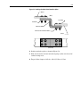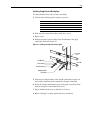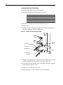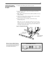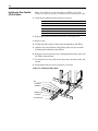
1
Bulletin 2300 Family
of Drive Systems
Hardware
Installation Instructions
Important User Information
Solid state equipment has operational characteristics differing from those of
electromechanical equipment. Safety Guidelines for the Application,
Installation and Maintenance of Solid State Controls (Publication SGI-1.1
available from your local Rockwell Automation sales office or online at
www.rockwellautomation.com/literature) describes some important differences
between solid state equipment and hard-wired electromechanical devices.
Because of this difference, and also because of the wide variety of uses for solid
state equipment, all persons responsible for applying this equipment must
satisfy themselves that each intended application of this equipment is
acceptable.
In no event will Rockwell Automation, Inc. be responsible or liable for indirect
or consequential damages resulting from the use or application of this
equipment.
The examples and diagrams in this manual are included solely for illustrative
purposes. Because of the many variables and requirements associated with any
particular installation, Rockwell Automation, Inc. cannot assume responsibility
or liability for actual use based on the examples and diagrams.
No patent liability is assumed by Rockwell Automation, Inc. with respect to use
of information, circuits, equipment, or software described in this manual.
Reproduction of the contents of this manual, in whole or in part, without
written permission of Rockwell Automation, Inc. is prohibited.
Throughout this manual, when necessary we use notes to make you aware of
safety considerations.
!
WARNING: Identifies information about practices or
circumstances that can cause an explosion in a hazardous
environment, which may lead to personal injury or death, property
damage, or economic loss.
Important: Identifies information that is critical for successful application and
understanding of the product.
!
ATTENTION: Identifies information about practices or
circumstances that can lead to personal injury or death, property
damage, or economic loss. Attentions help you:
• identify a hazard
• avoid the hazard
• recognize the consequences
Shock Hazard labels may be located on or inside the equipment
(e.g., drive or motor) to alert people that dangerous voltage may be
present.
Burn Hazard labels may be located on or inside the equipment
(e.g., drive or motor) to alert people that surfaces may be at
dangerous temperatures.
1336 FORCE, 1395, drove Tools, NRU, RGU, PLC-5 and CENTERLINE are registered trademarks of Rockwell Automation, Inc.
DriveExplorer, DriveExecutive, and SCANport are trademarks of Rockwell Automation, Inc.
PLC is a registered trademark of Rockwell Automation, Inc.
Table of Contents
Important User Information . . . . . . . . . . . . . . . . . . . . . . . . . . . . . . . . . . . . . . . . . . . . . . . 1-2
Summary of
Changes
Preface
Overview
Who Should Use This Manual . . . . . . . . . . . . . . . . . . . . . . . . . . . . . . . . . . . . . . . . . . . . .
Purpose of This Manual . . . . . . . . . . . . . . . . . . . . . . . . . . . . . . . . . . . . . . . . . . . . . . . . . .
How To Use This Manual . . . . . . . . . . . . . . . . . . . . . . . . . . . . . . . . . . . . . . . . . . . . . . . . .
Safety Precautions . . . . . . . . . . . . . . . . . . . . . . . . . . . . . . . . . . . . . . . . . . . . . . . . . . . . . . .
Contents of this Manual . . . . . . . . . . . . . . . . . . . . . . . . . . . . . . . . . . . . . . . . . . . . . . . . . .
Related Documentation . . . . . . . . . . . . . . . . . . . . . . . . . . . . . . . . . . . . . . . . . . . . . . . . . . .
Common Conventions Used
In This Manual . . . . . . . . . . . . . . . . . . . . . . . . . . . . . . . . . . . . . . . . . . . . . . . . . . . . . . . . .
Receiving Your Drive System . . . . . . . . . . . . . . . . . . . . . . . . . . . . . . . . . . . . . . . . . . . . . .
Rockwell Automation Support . . . . . . . . . . . . . . . . . . . . . . . . . . . . . . . . . . . . . . . . . . . . .
Chapter 1
P-1
P-1
P-1
P-2
P-3
P-4
P-5
P-5
P-6
Installing MCC Sections
Introduction . . . . . . . . . . . . . . . . . . . . . . . . . . . . . . . . . . . . . . . . . . . . . . . . . . . . . . . . . . . . 1-1
Before You Begin . . . . . . . . . . . . . . . . . . . . . . . . . . . . . . . . . . . . . . . . . . . . . . . . . . . . . . . 1-1
Preparing the System for Bus Splice Installation . . . . . . . . . . . . . . . . . . . . . . . . . . . . . . . 1-1
Preparing the Inside of an MCC: Panel-Mounted Units . . . . . . . . . . . . . . . . . . . . . . . . . 1-9
Putting the MCC Sections in Place . . . . . . . . . . . . . . . . . . . . . . . . . . . . . . . . . . . . . . . . . 1-10
Bolting Together Newly-Joined MCC Sections . . . . . . . . . . . . . . . . . . . . . . . . . . . . . . . 1-10
Splicing the Busbars Together. . . . . . . . . . . . . . . . . . . . . . . . . . . . . . . . . . . . . . . . . . . . . 1-12
Completing an MCC After Bus Splice Installation. . . . . . . . . . . . . . . . . . . . . . . . . . . . . 1-12
Chapter 2
Removing and Installing Bucket Units
Introduction . . . . . . . . . . . . . . . . . . . . . . . . . . . . . . . . . . . . . . . . . . . . . . . . . . . . . . . . . . . .
Before You Begin . . . . . . . . . . . . . . . . . . . . . . . . . . . . . . . . . . . . . . . . . . . . . . . . . . . . . . .
Removal Procedure . . . . . . . . . . . . . . . . . . . . . . . . . . . . . . . . . . . . . . . . . . . . . . . . . . . . . .
Installation Procedure . . . . . . . . . . . . . . . . . . . . . . . . . . . . . . . . . . . . . . . . . . . . . . . . . . . .
Chapter 3
Removing and Installing Roll-Out Chassis Units
Introduction . . . . . . . . . . . . . . . . . . . . . . . . . . . . . . . . . . . . . . . . . . . . . . . . . . . . . . . . . . . .
Before You Begin . . . . . . . . . . . . . . . . . . . . . . . . . . . . . . . . . . . . . . . . . . . . . . . . . . . . . . .
Removal Procedure . . . . . . . . . . . . . . . . . . . . . . . . . . . . . . . . . . . . . . . . . . . . . . . . . . . . . .
Installation Procedure . . . . . . . . . . . . . . . . . . . . . . . . . . . . . . . . . . . . . . . . . . . . . . . . . . . .
Chapter 4
2-1
2-1
2-2
2-5
3-1
3-1
3-2
3-5
Removing and Installing MCC Doors
Introduction . . . . . . . . . . . . . . . . . . . . . . . . . . . . . . . . . . . . . . . . . . . . . . . . . . . . . . . . . . . .
Before You Begin . . . . . . . . . . . . . . . . . . . . . . . . . . . . . . . . . . . . . . . . . . . . . . . . . . . . . . .
Removing an MCC Door . . . . . . . . . . . . . . . . . . . . . . . . . . . . . . . . . . . . . . . . . . . . . . . . .
Installing an MCC Door . . . . . . . . . . . . . . . . . . . . . . . . . . . . . . . . . . . . . . . . . . . . . . . . . .
4-1
4-1
4-1
4-2
2
Chapter 5
Installing Busbar Splices
Introduction . . . . . . . . . . . . . . . . . . . . . . . . . . . . . . . . . . . . . . . . . . . . . . . . . . . . . . . . . . . . 5-1
Before You Begin. . . . . . . . . . . . . . . . . . . . . . . . . . . . . . . . . . . . . . . . . . . . . . . . . . . . . . . . 5-1
Splicing Power Busbars . . . . . . . . . . . . . . . . . . . . . . . . . . . . . . . . . . . . . . . . . . . . . . . . . . . 5-2
Splicing Control Busbars . . . . . . . . . . . . . . . . . . . . . . . . . . . . . . . . . . . . . . . . . . . . . . . . . 5-12
Installing the Equipment Grounding Conductor (PE)
Bus Splice . . . . . . . . . . . . . . . . . . . . . . . . . . . . . . . . . . . . . . . . . . . . . . . . . . . . . . . . . . . . 5-15
Installing the Zero Potential (TE) Bus Splice . . . . . . . . . . . . . . . . . . . . . . . . . . . . . . . . . 5-16
Chapter 6
Installing Top Hat Assemblies and
Cutting Holes for Cable Entry/Exit
Introduction . . . . . . . . . . . . . . . . . . . . . . . . . . . . . . . . . . . . . . . . . . . . . . . . . . . . . . . . . . . . 6-1
Installing a Top Hat Assembly. . . . . . . . . . . . . . . . . . . . . . . . . . . . . . . . . . . . . . . . . . . . . . 6-1
Appendix A
Busbar Splice Kit Catalog Numbers
Introduction . . . . . . . . . . . . . . . . . . . . . . . . . . . . . . . . . . . . . . . . . . . . . . . . . . . . . . . . . . . . A-1
Understanding Catalog Numbers. . . . . . . . . . . . . . . . . . . . . . . . . . . . . . . . . . . . . . . . . . . . A-1
Busbar Splice Kit Catalog Numbers . . . . . . . . . . . . . . . . . . . . . . . . . . . . . . . . . . . . . . . . . A-2
Index
Summary of Changes
Changes made to this manual, since the last release, include:
1
For this updated information:
See:
Revised torque values on bus clamps
5-5, 5-6, 5-9 and
5-11
Publication 20D-UM002C-EN-P - November 2003
2
Notes:
Publication 20D-UM002C-EN-P - November 2003
Preface
Overview
Please read this preface to familiarize yourself with this manual. This
preface covers the following topics:
• who should use this manual
• the purpose of this manual safety precautions
• contents of this manual
• related documentation conventions used in this manual
• drive system receiving
• Rockwell Automation support
Who Should Use This
Manual
This manual is intended for those who are responsible for installing
Rockwell Automation drive systems.
!
ATTENTION: If you do not have a basic understanding of the
drive system, as designed, or of any product(s) used in the
system, contact your local Rockwell Automation representative
for information on available training courses before starting the
system.
Purpose of This Manual
This manual provides installation instructions for Rockwell Automation’s
Bulletin 2300 family of drive systems. The provided procedures are for
those tasks that need to be done at the customer site before system startup.
How To Use This Manual
When using this manual to install your drive system, you will begin and
complete the installation in Chapter 1 of this manual. Chapter 1 will refer
you to other chapters that address specific unit configuration instructions
and busbar splice installation instructions. When you are referred to another
chapter–go to that chapter, perform the required procedure(s), and then
return to Chapter 1.
Note: You can also refer to the appropriate chapter of this manual
whenever you need to:
• remove/install bucket units
• remove/install roll-out chassis units
• remove/install an MCC door
p-2
Safety Precautions
The following general precautions apply when installing, servicing, or
operating Bulletin 2300 drive system lineups:
!
ATTENTION: Only those familiar with the drive
system, the products used in the system, and the
associated machinery should plan or implement the
installation, startup, and future maintenance of the
system. Failure to comply can result in personal injury
and/or equipment damage.
ATTENTION: Verify that all sources of AC and DC
power are deenergized and locked out or tagged out in
accordance with the requirements of ANSI/NFPA 70E,
Part II.
ATTENTION: The system may contain stored energy
devices. To avoid the hazard of electrical shock, verify
that all voltage on capacitors has been discharged before
attempting to service, repair, or remove a drive system
or its components. You should only attempt the
procedures in this manual if you are qualified to do so
and are familiar with solid-state control equipment and
the safety procedures in ANSI/NFPA 70E.
ATTENTION: An incorrectly applied or incorrectly
installed drive system can result in component damage
and/or a reduction in product life. Wiring or application
errors–such as undersizing the motor, incorrect or
inadequate AC supply, and excessive ambient
temperatures–can result in the malfunction of the drive
equipment.
ATTENTION: This drive system contains parts and
assemblies that are sensitive to ESD (electrostatic
discharge). Static control precautions are required when
installing, testing, or repairing this assembly.
Component damage can result if ESD control procedures
are not followed. If you are not familiar with static
control procedures, refer to Allen-Bradley publication
8000-4.5.2, Guarding Against Electrostatic Damage, or
another adequate handbook on ESD protection.
p-3
Contents of this Manual
Chapter
Title
Contents
Preface
Purpose, background, and scope of this manual.
1
Installing MCC Sections
Procedures for installing CENTERLINE™ MCC cabinet sections.
2
Removing and Installing Bucket Units
Procedures for removing and installing bucket units.
3
Removing and Installing Roll-Out Chassis Units
Procedures for removing and installing roll-out chassis units.
4
Removing and Installing MCC Doors
Procedures for removing and installing a door on an MCC cabinet.
5
Installing Busbar Splices
Procedures for installing power, control, PE, and TE bus splices.
6
Installing Top Hat Assemblies and
Cutting Holes for Cable Entry/Exit
Procedures for installing top hat assemblies and cutting holes in MCCs.
A
Busbar Splice Kit Catalog Numbers
A list of busbar splice kits with catalog numbers.
p-4
Related Documentation
The following documents include information that may be helpful when
installing or services components in your drive system. To obtain a copy of
any of the Rockwell Automation publications, contact your local Rockwell
Automation office or distributor.
For
Read This Document
Document Number
Information on the 1336 FORCE™ drives
1336T User Manual – AC Drives
1336 FORCE-5.12
Information on the 1336 PLUS™ drives
1336S User Manual – .05-600HP
1336 PLUS-5.0
Information on low-kVA 1395™ drives
1395 Installation Manual – Digital DC Drive
1395-5.40
Information on medium-kVA 1395 drives
1395 Installation Manual – Digital DC Drive in Motor 1395-5.60
Control Center
Information on high-kVA 1395 drives
1395 Installation Manual – Digital DC Drive in
Bulletin 2361 Motor Control Center
2361-5.01
PLC-5™ information
PLC-5 Controllers Brochure
1785-1.2
Additional information on joining and splicing together MCCs
Instructions – Joining and Splicing Vertical Sections 2100-5.1
Details on receiving, handling, and storing MCCs
Instructions – Receiving, Handling, and Storing
Motor Control Centers
2100-5.5
Information on 2364E non-regenerative front-end units (NRU™)
NRU User Manual
2364E-5.01
Information on 2364F regenerative front-end units (RGU™)
RGU User Manual
2364F-5.01
A description of DriveTools™ software
DriveTools Software Brochure
9303-1.0
Articles on wire sizes and types for grounding electrical
equipment
National Electrical Code (NFPA 70)
Published by NFPA of
Boston, MA; ANSI/NFPA70
Articles on safety procedures
Standard for Electrical Safety Requirements for the NFPA 70E
Employee Workplace
Instruction for handling, installing, operating, and maintaining
motor control centers
Instructions for the Handling, Installation, Operation, NEMA ICS 2.3
and Maintenance of Motor Control Centers
A complete listing of current Allen-Bradley documentation,
including ordering instructions. Also indicates whether the
documents are available on CD-ROM or in multi-languages
Allen-Bradley Publication Index
SD499
A glossary of industrial automation terms and abbreviations
Allen-Bradley Industrial Automation Glossary
AG-7.1
p-5
Common Conventions Used The following conventions are used throughout this manual:
In This Manual
• Bulleted lists such as this provide information, not procedural steps.
• Numbered lists provide sequential steps or hierarchical information.
• When we refer you to another section/document, that name appears in
italics.
• The exclamation point inside a triangle followed by the word
“ATTENTION” indicates circumstances that can lead to personal
injury, death, property damage, or economic loss.
Receiving Your Drive
System
You, the customer, are responsible for thoroughly inspecting the equipment
before accepting the shipment from the freight company. Check the item(s)
that you receive against your purchase order. If any items are obviously
damaged, do not accept the delivery until the freight agent has noted the
damage on the freight bill. Should you discover any concealed damage
during unpacking, you are responsible for notifying the freight agent. In
such a case, leave the shipping container intact and request that the freight
agent make a visual inspection of the equipment.
p-6
Rockwell Automation
Support
Rockwell Automation offers support services worldwide, with Sales/
Support Offices, authorized distributors, and authorized Systems Integrators
located throughout the United States, plus Rockwell Automation
representatives in every major country in the world.
Local Product Support
Please contact your local Rockwell Automation representative for:
• sales and order support
• product technical training
• warranty support
• support service agreements
Technical Product Assistance
If you need to contact us for technical assistance, please review the product
information in the appropriate product manual first. Then call your local
Rockwell Automation representative. For the quickest possible response,
we recommend that you have the catalog numbers of your products
available when you call.
Chapter
1
Installing MCC Sections
Introduction
This chapter provides procedures for installing CENTERLINE Bulletin
2100 motor control center sections.
Before You Begin
Before you begin installation, be sure you have the following:
• The MCC sections containing the drive system
• Tool(s) you will need to:
– remove and tighten screws:
slotted screw
slotted/phillips screw
#10 thread-forming hexhead screw (0.312” across flats)
¼” thread-forming screw (0.375” across flats)
– remove and tighten bolts:
¼” bolt (0.438” across flats)
½” bolt (0.750” across flats)
– secure screws with nuts:
¼”-20 nut (0.438” across flats)
Preparing the System for
Bus Splice Installation
Follow these procedures to prepare the MCC sections for installation:
Important: Physical restrictions at your installation site may not allow the
following sequences to be followed exactly as stated.
Unpacking the MCC Sections
1. Remove the MCCs from their packaging.
Important: Be sure to handle the MCCs according to the instructions
provided in CENTERLINE Motor Control Centers (AB
Publication 2100-5.5).
2. Remove all splice kits and labels from wireways, blank unit spaces, and
other external packaging.
Note: A label on the outside of a compartment designates the location of splice kits
located within a horizontal wireway or blank unit space.
Note: Keep track of splice kits. Misplaced splice kits may not have immediate
replacements available.
1-2
Preparing the Outside of an MCC
For each MCC that is to be joined to an adjacent MCC, do the following:
1. Remove the MCC’s lower wireway cover, if presently attached, by
unfastening 2 screws. See Figure 1.1.
Figure 1.1 Removing an MCC’s Lower Wireway Cover
Lower Wireway
Cover
Front View
1-3
2. Remove the four end-cover plates, if present, from the sides of MCCs
that will be joined to other MCCs. Unfasten the 4 screws that secure
each plate. This will expose joining holes. See
Figure 1.2.
Figure 1.2 Removing the End Covers and Power Bus Plate
Side View (R.H.)
Upper
End Covers
Power Bus
Plate
Lower
End Covers
3. Remove the power-bus plates, if present, from the sides of MCCs that
will be adjacent to other MCCs. To remove a power bus plate, unfasten
10 screws. Refer to Figure 1.2.
1-4
4. Remove all screws and plastic plugs from joining holes. Refer to Figure
1.3 for hole locations.
Figure 1.3 Location of Joining Holes
Side View (R.H.)
Joining Hole
Joining Hole
Joining Hole
Joining Hole
Joining Hole
Joining Hole
Joining Hole
1-5
Preparing the Inside of an MCC
For each MCC that is to be joined to an adjacent MCC, do the following:
If the MCC contains a:
Typical Units
Go to:
Roll-out chassis unit
2362 (D-G frame units),
2364F (K-N codes)
Preparing the Inside of an MCC:
Roll-Out Chassis Units (see page 1-6)
Bucket units
2362 (A-C frame units)
Preparing the Inside of an MCC:
Bucket Units (see page 1-7)
Panel-mounted unit
2361 units, 2364E units,
2364F (J-code units)
Preparing the Inside of an MCC:
Panel-Mounted Units (see page 1-9)
1-6
Preparing the Inside of an MCC: Roll-Out Chassis Units
1.
If the MCC contains a:
Then:
A 2362 (D-G frame) or 2364F
(K-N code) roll out chassis unit.
Follow the procedures in Chapter 3 to remove
the roll-out chassis from the MCC.
2. Remove the horizontal bus access cover, if not already removed, to
expose the bus ends for splicing. Each horizontal bus access cover is
secured with two screws. Reference Figure 1.4.
Figure 1.4 Removing the Horizontal Bus Access Cover in an MCC that Contains a
Roll-Out Chassis Unit
Hole s
Holes
N otch
Notch
No tch
Notch
Horizontal Bus
Access Cover
3. Pull all bottom-entry cables, if present, through the conduit(s) to a spot
where you can reach them after you have put the MCCs in place.
1-7
Preparing the Inside of an MCC: Bucket Units
1.
If the MCC will be spliced on:
Then:
Right side
Loosen 3 screwlatches to open the vertical
wireway door on the right side. See Figure 1.5.
Left side
Follow the procedures in Chapter 2 to remove
any buckets blocking access to the horizontal
bus and joining holes.
Figure 1.5 Removing the Vertical Wireway Door
Vertical
Wireway Door
Left
Side
Right
Side
1-8
2. Remove the splice-opening cover on the joining side of the MCC. Refer
to Figure 1.6.
Figure 1.6 Removing the Splice-Opening Cover
Splice Opening
Cover
3. Pull all bottom-entry cables, if present, through the conduits to a spot
where you can reach them after you have put the MCCs in place.
1-9
Preparing the Inside of an
MCC: Panel-Mounted Units
1. Remove the horizontal bus access cover from the joining side of the
MCC, as indicated in Figure 1.7.
Figure 1.7 Removing the Horizontal Bus Access Cover from an MCC Containing a
Panel-Mounted Unit
Horizontal Bus
Access Cover
2. Pull all bottom-entry cables, if present, through the conduit(s) to a spot
where you can reach them after you have put the MCCs in place.
1-10
Putting the MCC Sections in Use the following procedure to put the MCC sections in place:
Place
1. Move the MCC sections into place according to the instructions provided
in CENTERLINE Motor Control Centers (AB Publication 2100-5.5).
2. Level the MCCs.
3. Fasten the MCCs to the floor.
Note: Each MCC has two holes for securing the MCC to the floor with
1/2” bolts. These two holes are located in the center front and center
rear of each MCC bottom.
Follow this procedure for bolting together newly-joined MCC sections:
Bolting Together
Newly-Joined MCC Sections Important: Use the hardware furnished with the power bus splice kits.
1. Verify that the following hardware is present for each pair of sections to
be bolted together:
2. At every hole labeled “A” on Figure 1.8, pass a thread-forming screw
from inside the left-hand section and engage the screw with the
respective hole in the right-hand section.
3. At the hole labeled “B” on Figure 1.8, pass the 1/4-20 x 5/8” hex-head
screw from inside the left-hand section through the respective hole in the
right-hand section and secure with the flat washer and steel nut.
1-11
Figure 1.8 Labeled Locations of Joining Holes
Side View (L.H.)
A
Side View (R.H.)
A
A
A
A
B
A
Back
A
B
A
A
A
A
A
Back
1-12
Splicing the Busbars
Together
After all MCC sections have been bolted together, do the following:
!
ATTENTION: This drive contains ESD (Electrostatic
Discharge) sensitive parts and assemblies. Status control
precautions are required when installing, testing, or repairing this
assembly. Component damage can result if ESD control
procedures are not followed. If you are not familiar with static
control procedures, refer to Allen-Bradley publication
8000-4.5.2, Guarding Against Electrostatic Damage, or any other
applicable ESD protection handbook.
1. Install busbar splices according to the procedures in Chapter 5.
2. Inspect the interior for dust and dirt. Vacuum as needed.
Important: Do not clean using compressed air because it contains moisture
and may blow debris into the control equipment.
3. Verify that no tools or hardware have been dropped inside the MCCs.
Completing an MCC After
Bus Splice Installation
Follow this procedure for each MCC that you have joined to an adjacent
MCC.
Table 1.A Completing the Inside of an MCC
If the MCC contains a:
Typical Units
Go to:
Roll-out chassis unit
2362 (D-G frame units),
2364F (K-N codes)
Completing the Inside of an MCC:
Roll-Out Chassis Units (see page 1-13)
Bucket units
2362 (A-C frame units)
Preparing the Inside of an MCC:
Bucket Units (see page 1-13)
Panel-mounted unit
2361 units, 2364E units,
2364F (J-code units)
Preparing the Inside of an MCC:
Panel-Mounted Units (see page 1-13)
1-13
Completing the Inside of an MCC: Roll-Out Chassis Units
1. Install the horizontal bus access cover. Each horizontal bus access cover
is secured with two screws (see Figure 1.4).
2.
If the MCC contains a:
Then:
A 2362 (D or E-frame) or 2364F
(K or L-code) roll out chassis unit.
1.Follow the procedures in Chapter 3 to install
the roll-out chassis from the MCC.
2.Go to Completing the Output of an MCC
(page 1-14).
A 2362 (F or G-frame) or 2364F
(M or N-code) roll-out chassis unit.
Go to Completing the Outside of an MCC
(page 1-14).
Completing the Inside of an MCC: Bucket Units
1. Install the splice-opening cover on the joining side of the MCC (see
Figure 1.6).
2.
If the MCC will be spliced on:
Then:
Right side
1.Close the vertical wireway door and secure the
door by tightening the 3 screwlatches (Figure
1.5).
2.Go to Completing the Outside of an MCC.
Left side
1.Follow the procedures in Chapter 2 to remove
any buckets that were removed.
2.Go to Completing the Outside of an MCC
(page 1-14).
Completing the Inside of an MCC: Panel-Mounted Units
1. Install the horizontal bus access cover (see Figure 1.7).
2. Go to Completing the Outside of an MCC.
1-14
Completing the Outside of an MCC
For all MCCs that were just joined to adjacent MCCs, do the following:
1. Position the MCC’s lower wireway cover.
2. Fasten the two screws that secure the lower wireway cover to the MCC
(see Figure 1.1).
Chapter
2
Removing and Installing Bucket Units
Introduction
This chapter provides procedures for removing and installing bucket units.
Before You Begin
Before you begin installation, be sure you have the following:
• Tool(s) you will need to:
– disconnect and connect wires
– loosen and tighten slotted screwlatches that secure the bucket to the
MCC
2-2
Removal Procedure
Follow the procedure below to remove bucket units from an MCC:
!
ATTENTION: To avoid the hazard of electrical shock, verify
that all voltages on the system bus network have been discharged
before attempting to service the system.
1. Open the door of the MCC.
Note: Removal of the door is not necessary.
2.
If:
Then:
You want to remove the door
Follow the door removal procedure in
Chapter 4.
If:
Then:
The unit to be removed is less than 2
space factors
Disengage the screwlatches at the front of the
bucket unit – one at the top and one at the
bottom. See Figure 2.1.
Otherwise
Disengage the screwlatches at the front of the
bucket unit – two at the top and one at the
bottom. See Figure 2.1.
3.
Figure 2.1 Screwlatch Locations
Screwlatch
Screwlatch
2-3
4. Disconnect all wires that connect the module to stationary devices in the
MCC.
Important: If any of these wires remain intact, you will not be able to freely
remove the module from the MCC.
!
ATTENTION: The 2362 A-frame bucket weighs
approximately 45 pounds (21 kg); the B-frame bucket weighs
approximately 90 pounds (41 kg); and the
C-frame bucket weighs approximately 140 pounds
(64 kg). Failure to take precautions when moving a bucket may
result in personal injury and/or damage to equipment.
ATTENTION: Do not force the bucket when removing it from
the MCC. If you cannot easily remove the bucket, verify that all
necessary wires have been disconnected.
ATTENTION: After the bucket has been removed from the
MCC, secure the bucket so that it will not tip over or fall, causing
personal injury and/or equipment damage.
5. Disconnect customer wiring at the bottom of the bucket and slide the
wiring into the vertical wireway.
2-4
6. Pull the bucket forward to unplug from the vertical bus, holding the
upper right-hand latch assembly and the lower left-hand tab handle. See
Figure 2.2.
Figure 2.2 Bucket Connections
Top View of Enclosure
Back
Vertical Bus
Vertical Ground
Vertical Wireway
L1
L2
L3
PE
Front
Top View of Bucket
Note: Figure 2.2 shows the configuration for a common-AC-bus system.
For a common-DC-bus system, the middle vertical bus and clip (L2)
shown above are not present.
2-5
Installation Procedure
Follow the procedure below to install a bucket unit into an MCC:
ATTENTION: To avoid the hazard of electrical shock, verify
that all voltages on the system bus network have been discharged
before attempting to service the system.
!
ATTENTION: The 2362 A-frame bucket weighs
approximately 45 pounds (21 kg); the B-frame bucket weighs
approximately 90 pounds (41 kg); and the
C-frame bucket weighs approximately 140 pounds
(64 kg). Failure to take precautions when moving a bucket may
result in personal injury and/or damage to equipment.
1. Open the door of the MCC.
2. Verify that the bucket and vertical bus are either DC or AC (both the
bucket and vertical bus should have L1, L2, and L3; or L1 and L3 only).
See Figure 2.3.
Figure 2.3 Valid Bucket Connections
DC Vertical Bus
3-Phase AC Vertical Bus
Yes
Yes
L1
L2
L1
L3
Bucket
No
L3
Bucket
No
3. Push the bucket backward to plug into the vertical bus, holding the upper
right-hand latch assembly and the lower left-hand tab handle (Figure 2.2
shows how the bucket will plug into the vertical power and ground
buses).
2-6
4. Connect customer wiring at the bottom of the bucket, as appropriate.
5. Connect all wires that connect the module to stationary devices in the
MCC.
6.
If:
Then
The unit to be removed is less than 2
space factors
Engage the screwlatches at the front of the
bucket unit – one at the top and one at the
bottom. See Figure 2.1.
Otherwise
Engage the screwlatches at the front of the
bucket unit – two at the top and one at the
bottom. See Figure 2.1.
7. If the door has been removed, follow the door installation procedure
found in Chapter 4.
Chapter
3
Removing and Installing Roll-Out Chassis Units
Introduction
This chapter provides the necessary steps to remove and install
roll-out chassis units.
Before You Begin
Before you begin installation, be sure you have the following:
• Tool(s) you will need to:
– disconnect and connect wires
– remove and tighten screws:
#10 thread-forming hexhead screw (0.312” across flats)
¼” thread-forming screw (0.375” across flats)
– remove and tighten bolts:
3/8” bolt (0.563” across flats)–for D/F-frame 2362 units
and K-code 2364F units
M10 bolt (17 mm across flats)–for G-frame 2362 units
and M/N-code 2364F units
• A means to remove the roll-out chassis unit
3-2
Removing and Installing Roll-Out Chassis Units
Removal Procedure
Follow the procedure below to remove roll-out chassis units from an MCC.
ATTENTION: To avoid the hazard of electrical shock, verify
that all voltages on the system bus network have been discharged
before attempting to service the system.
!
1. Open door of MCC.
2. Remove two screws to detach the lower wireway cover, if presently
attached. Refer to Figure 3.1.
Figure 3.1 Removing the Lower Wireway Cover
Example of Typical
Shipping Brace
Lower Wireway
Cover
(TYP)
3. Remove shipping brace (if present).
4. Remove a total of four screws to detach both of the lower reinforcing
angles as shown in Figure 3.2 (used in D, E, F-frame 2362 units and in K
and L-code 2364F units).
Removing and Installing Roll-Out Chassis Units
3-3
5. If the sealing angle (shown in Figure 3.2) obstructs the roll-out chassis
from rolling out, remove the sealing angle.
6. For G-frame 2362 units and M or N-code 2364F units, remove the lower
brace, which is shown in Figure 3.2.
7. Remove both of the lower mounting angles, as shown in
Figure 3.2, by unfastening four screws each (used in D, E, and
F-frame 2362 units, and in K and L-code 2364F units).
Figure 3.2 Typical Mounting Hardware By Unit
E-frame 2362, F-frame 2362
or L-code 2364F
D-frame 2362 or
K-code 2364F
G-frame 2362, M-code 2364F,
or N-code 2364F
Upper
Mounting
Bracket
Upper
Mounting
Bracket
Mounting
Angle (Typ. 2)
Reinforcing
Angle (Typ. 2)
Lower
Brace
Sealing
Angle
3-Dimensional View
Mounting
Angle
Reinforcing
Angle
3-4
Removing and Installing Roll-Out Chassis Units
8.
If the module size is:
Do this:
D, F, or G-frame 2362 units or
K, M, or N-code 2364F units
Remove a total of two bolts to unfasten the
chassis unit from the upper brackets. Refer to
Figure 3.2.
E-frame 2362 units or
L-code 2364F units
Remove a total of four screws to unfasten the
chassis unit from the upper brackets. Refer to
Figure 3.2.
9. Disconnect all wires that connect the chassis unit to stationary devices in
the MCC.
Important: If any of these wires remain intact, you will not be able to freely
remove the chassis unit from the MCC.
!
ATTENTION: 2362 chassis units have the following
approximate weights: D-frame, 260 lbs (119 kg);
E-frame, 440 lbs (200 kg); F-frame 675 lbs (306 kg); and
G-frame 1000 lbs (455 kg). 2364F chassis units have the
following approximate weights: K-code, 260 lbs (119 kg);
L-code, 440 lb (200 kg); M-code, 1000 lbs
(455 kg); and N-code, 1000 lbs (455 kg). Failure to take
precautions when moving a chassis unit may result in personal
injury and/or damage to equipment.
ATTENTION: Do not force the chassis unit when removing it
from the MCC. If you cannot easily remove the chassis unit,
verify that all necessary wires have been disconnected.
ATTENTION: After the chassis unit has been removed from
the MCC, secure the chassis unit so that it will neither tip over
nor fall, causing personal injury and/or equipment damage.
10.Carefully remove the chassis unit from the MCC according to your
company’s handling instructions.
Removing and Installing Roll-Out Chassis Units
Installation Procedure
3-5
Follow the procedures below to install a roll-out chassis unit into its MCC.
!
ATTENTION: To avoid the hazard of electrical shock, verify
that all voltages on the system bus network have been discharged
before attempting to service the system.
ATTENTION: 2362 chassis units have the following
approximate weights: D-frame, 260 lbs (119 kg);
E-frame, 440 lbs (200 kg); F-frame 675 lbs (306 kg); and
G-frame 1000 lbs (455 kg). 2364F chassis units have the
following approximate weights: K-code, 260 lbs (119 kg);
L-code, 440 lb (200 kg); M-code, 1000 lbs
(455 kg); and N-code, 1000 lbs (455 kg). Failure to take
precautions when moving a chassis unit may result in personal
injury and/or damage to equipment.
1. Reposition the chassis unit into the MCC according to your company’s
handling instructions.
2. Connect all wires that you disconnected between the chassis unit and
devices in the MCC.
3.
If the module size is:
Do this:
D, F, or G-frame 2362 units or
K, M, or N-code 2364F units
Replace the two bolts to fasten the chassis unit
to the upper brackets. See Figure 3.2.
E-frame 2362 units or
L-code 2364F units
Replace the four screws to fasten the chassis
unit to the upper brackets. See Figure 3.2.
3-6
Removing and Installing Roll-Out Chassis Units
4. Fasten four screws to attach the lower mounting angles
(see Figure 3.2).
5. For G-frame 2362 units and M or N-code 2364F units, fasten the two
screws to attach the lower brace
6. If the sealing angle has been removed, fasten the two screws to attach the
sealing angle (see Figure 3.2).
7. Install four screws to attach both of the lower reinforcing angles.
8. Fasten two screws to attach the lower wireway cover (shown in Figure
3.2).
Chapter
4
Removing and Installing MCC Doors
Introduction
This chapter provides the necessary steps to remove and install MCC doors.
Before You Begin
Before you begin your installation, be sure you have the following:
• Tool(s) you will need to:
– remove a door hinge (i.e. - standard screwdriver)
– disconnect door-mounted devices
Removing an MCC Door
!
ATTENTION: The system may contain stored energy devices.
To avoid the hazard of electrical shock, verify that all voltage on
capacitors has been discharged before attempting to service,
repair, or remove a drive system or its components. You should
only attempt the procedures in this manual if you are qualified to
do so and are familiar with solid-state control equipment and the
safety procedures in publication NFPA 70E.
Follow this procedure to remove an MCC door:
1. Open door completely.
2. Disconnect door-mounted devices, as appropriate.
Important: Before disconnecting, be sure to note the assembly/wiring of
devices and re-label wire labels if they cannot be easily read.
3. Remove hinge pins by sliding them up out of the hinge. You can use a
screwdriver to make pin removal easier.
4. Swing door carefully to a nearly closed position.
5. Lift door up and off.
4-2
Installing an MCC Door
Follow this procedure to install an MCC door:
1. With door in a nearly-closed position, place door onto hinges in its
proper orientation.
2. Carefully open door completely.
3. Replace hinge pins by sliding them into hinges.
4. Connect door-mounted devices per your notes.
Chapter
5
Installing Busbar Splices
Introduction
This chapter provides the necessary steps to install power, control,
equipment grounding conductor (PE), and zero potential (TE) bus splices.
Before You Begin
Before you begin your installation:
1. Verify that MCCs have been joined together as specified by instructions
provided in Chapter 1.
2. Be sure you have the following:
• One PE / TE (equipment grounding conductor / zero potential) bus splice
kit for every two sections just joined.
• One control bus splice kit, if both sections have a control bus, for every
two sections just joined.
• One power bus splice kit for every two sections just joined.
• Tool(s) you will need to:
– tighten screws:
1/4” thread-forming screw (0.375” across flats)
– torque bolts:
1/4” bolt (0.438” across flats)
– secure screws and nuts:
1/4” nut (0.438” across flats)
3/8” nut (0.563” across flats)
5-2
Splicing Power Busbars
Follow the procedures contained in this section to splice the two halves of
each power bus in every pair of MCCs that you have joined together.
Note: A common-DC-bus system will have 2 separate power busses; and a
common-AC-bus system will have 3 separate power busses.
The following table will help you to determine the type of power bus splice
that needs to be installed. This table addresses the various bus
configurations available in a 20-inch-deep MCC, the standard depth used by
Rockwell Automation Drive Systems.
If:
Then:
Both ends of the power bus to be joined
are at a depth of either 11.92 inches
(303 mm) or 16.92 inches (430 mm):
1. Reference Figure 5.1(a).
2. Go to Installing Straight Power Bus Splices.
One end of the power bus to be joined is at 1. Reference Figure 5.1(b).
a depth of 11.92 inches (303 mm); the
2. Go to Installing Straight Power Bus Splices.
other 16.92 inches (430 mm):
5-3
Figure 5.1 Top Views of Various Power Bus Splice Configurations!
a. Both Ends of the Power Bus at the Same Depth
Front
Front
b. One End of the Power Bus at a Depth of 11.92 inches (303 mm); the Other, 16.92 inches (430 mm)
Front
Front
! All views show a dual busbar configuration. In a single busbar configuration, only a single splice is used.
Installing Straight Power Bus Splices
If each power bus consists of:
Then go to:
A single bar
Installing Straight Power Bus Splices: Single Bar
Two bars
Installing Straight Power Bus Splices: Dual Bar
5-4
Installing Straight Power Bus Splices: Single Bar
1. Verify that the following splice hardware is present:
Description
Common DC
Bus Quantity
Common AC
Bus Quantity
8-hole, straight busbar splice
2
3
Bus clamps!
8
12
Flat washer
16
24
Nut/conical-spring washer
16
24
! For each busbar end with built-in clamps, decrease the required quantity by 2.
!
ATTENTION: Verify that the busbar splices are of the same
thickness as the busbars to be spliced.
For lineups containing common bus F-frame 2362 units, any
G-frame 2362 units, or M/N-code 2364F units, the bus splices
should be sized to match the overall bus rating of the lineup. See
Figure 1.15 for an example.
Figure 5.2 Splicing with G-Frame 2362 Units or M/N-Code 2364F Units–Example
G-frame
Unit
Other Unit on
the Common Bus
Select the appropriate clamps for each connection
according to the table below.
Clamp Length
1.75”
2.00”
2.25”
Use When Splicing
800A (0.13”) or 1200A (0.25”) bus
1600A (0.5”) bus
2000A (0.63”) or 3000A (0.75”) bus
Bus Section
Rated 800-3000A
Bus Splice
Rated 800A
Bus Section
Rated 800A
In this example, the overall bus is rated for 800A.
5-5
2. Verify that contact surfaces are free of dirt/debris. Deburr edges as
necessary.
3. Insert the bus clamps, from the backside, through the holes at the ends of
the busses to be joined. Refer to Figure 5.3.
Note: Bus clamps will only fit into the busbar holes in the vertical
orientation.
Figure 5.3 Installing a Straight Power Bus Splice, Single Bar
Power Bus
Bus Clamp
(Back)
Flat Washer
Splice Bar
One-Piece Nut and Conical Washer
(Front View)
4. Slide one busbar splice over the ends of the bus clamps as shown in
Figure 5.3.
5. Slide one flat washer and one nut/conical-spring washer over the end of
each bus-clamp screw.
6. Torque all bus clamps to 38 lb-ft ± 2 lb-ft (52 N-m ± 3 N-m).
5-6
Installing Straight Power Bus Splices: Dual Bar
For each power bus in the system, follow this procedure:
1. Verify that the following splice hardware is present:
Description
Common DC
Bus Quantity
Common AC
Bus Quantity
8-hole, straight busbar splice
4
6
Bus clamps!
8
12
Flat washer
16
24
Nut/conical-spring washer
16
24
! For each busbar end with built-in clamps, decrease the required quantity by 2.
!
ATTENTION: Verify that the busbar splices are of the same
thickness as the busbars to be spliced.
For lineups containing common bus F-frame 2362 units, any
G-frame 2362 units, or M/N-code 2364F units, the bus splices
should be sized to match the overall bus rating of the lineup. See
Figure 1.15 for an example.
2. Verify that contact surfaces are free of dirt/debris. Deburr edges as
necessary.
3.
If:
Then:
Either bus has a built-in
bus clamp
1. Insert the bus clamps, from the backside,
through the holes at the ends of the busses without
built-in bus clamps. See Figure 5.3(a).
2. Slide two busbar splices over the ends of the
bus clamps on the front-side of the bus.
Neither bus has a built-in
bus clamp
1. Position one busbar splice behind the bus as
shown in Figure 5.3(b).
2. Insert the bus clamps, from the backside,
through the busbar splice and bus.
3. Slide the second busbar splice over the ends of
the bus clamps.
4. Slide one flat washer and one nut/conical-spring washer over the end of
each bus-clamp screw.
5. Torque all bus clamps to 38 lb-ft ± 2 lb-ft (52 N-m ± 3 N-m).
5-7
Figure 5.4 Installing a Straight Power Bus Splice with Dual Bars
a. When a Power Bus has a Built-In Bus Clamp
Built-In Bus Clamp
Power Bus
Bus Clamp
(Back)
Flat Washer
Splice Bars
One-Piece Nut and Conical Washer
(Front View)
b. When Neither Power Bus has a Built-In Bus Clamp
Power Bus
Bus Clamp
(Back)
Flat Washer
Splice Bars
One-Piece Nut and Conical Washer
(Front View)
5-8
Installing Offset Power Bus Splices
If each power bus consists of:
Then go to:
A single bar
Installing Offset Power Bus Splices: Single Bar
Two bars
Installing Offset Power Bus Splices: Dual Bar
Installing Offset Power Bus Splices: Single Bar
For each power bus in the system, follow this procedure:
1. Verify that the following splice hardware is present:
Description
Common DC
Bus Quantity
Common AC
Bus Quantity
8-hole, offset busbar splice
2
3
Bus clamps!
8
12
Flat washer
16
24
Nut/conical-spring washer
16
24
! For each busbar end with built-in clamps, decrease the required quantity by 2.
2.
!
ATTENTION: Verify that the busbar splices are of the same
thickness as the busbars to be spliced.
For lineups containing common bus F-frame 2362 units, any
G-frame 2362 units, or M/N-code 2364F units, the bus splices
should be sized to match the overall bus rating of the lineup. See
Figure 5.2 for an example.
3. Verify that contact surfaces are free of dirt/debris. Deburr edges as
necessary.
4. Insert the bus clamps as indicated in Figure 5.5.
5-9
Figure 5.5 Installing a Single Bar Offset Power Bus Splice
Busbar
(Back)
Bus Clamp
Flat Washer
Splice Bar
One-Piece Nut and Conical Washer
Busbar
(Front View)
5. Position one busbar splice as shown in Figure 5.5.
6. Slide one flat washer and one nut/conical-spring washer over the end of
each bus-clamp screw.
7. Torque all bus clamps to 38 lb-ft ± 2 lb-ft (52 N-m ± 3 N-m).
5-10
Installing Offset Power Bus Splices: Dual Bar
For each power bus in the system, follow this procedure:
1. Verify that the following splice hardware is present:
Description
Common DC
Bus Quantity
Common AC
Bus Quantity
8-hole, offset busbar splice
4
6
Bus clamps!
8
12
Flat washer
16
24
Nut/conical-spring washer
16
24
! For each busbar end with built-in clamps, decrease the required quantity by 2.
!
ATTENTION: Verify that the busbar splices are of the same
thickness as the busbars to be spliced.
2. Verify that contact surfaces are free of dirt/debris. Deburr edges as
necessary.
3. Insert the bus clamps as indicated in Figure 5.6.
5-11
Figure 5.6 Installing a Dual Bar Offset Power Bus Splice
Busbar
(Back)
Bus Clamp
Flat Washer
Splice Bars
One-Piece Nut and Conical Washer
Busbar
(Front View)
4. Position one busbar splice as shown in Figure 5.6.
5. Slide one flat washer and one nut/conical-spring washer over the end of
each bus-clamp screw.
6. Torque all bus clamps to 38 lb-ft ± 2 lb-ft (52 N-m ± 3 N-m).
5-12
Splicing Control Busbars
Follow the procedures contained in this section to join the two halves of
both control busses in ever pair of MCCs that needs to be spliced together.
The following table will help you to determine the type of control bus splice
that needs to be installed. This table addresses the various bus
configurations available in a 20-inch-deep MCC, the most popular depth
used by Rockwell Automation Drive Systems.
If:
Then go to:
Both ends of the control bus to be joined are at a
depth of either 11.92 inches (303 mm) or
16.92 inches (430 mm):
Installing Straight Control Bus Splices
One end of the control bus to be joined is at a depth Installing Offset Control Bus Splices
of 11.92 inches (303 mm); the other,
16.92 inches (430 mm):
5-13
Installing Straight Control Bus Splices
Use this procedure if bus ends are at the same depth:
1. Verify that the following splice hardware is present:
Description
Quantity
2-hole, straight busbar splice
2
1/4-20 x 3/4” hex-head screw
4
Flat washer
4
Lockwasher
4
2. Slide one lock washer and one flat washer onto a screw.
3. Repeat 2 once.
4. Position one busbar splice in front of the discontinuity in the upper
control bus. Reference Figure 5.7.
Figure 5.7 Installing a Straight Control Bus Splice
Threaded
Insert
L1
Flat Washer
Lock washer
Hex-Head Screw
120 V AC
N
Straight Control
Bus Splice
5. Align the two elongated hoes of the straight control busbar splice over
the two holes bordering the discontinuity in the upper control bus.
6. Fasten the straight control busbar splice to the upper control bus, from
the front, using the same two hex head screws.
7. Torque both hex head screws to 108 lb-in (12.2 N-m).
8. Repeat 2 through 7 to splice together the lower control bus.
5-14
Installing Offset Control Bus Splices
Use this procedure if bus ends are offset in depth:
1. Verify that the following splice hardware is present:
Description
Quantity
2-hole, offset busbar splice
2
1/4-20 x 3/4” hex-head screw
4
Flat washer
4
Lockwasher
4
2. Slide one lock washer and one flat washer onto one screw.
3. Repeat 2 once.
4. Position one offset control busbar splice in front of the discontinuity in
the upper control bus. Reference Figure 5.8.
Figure 5.8 Installing an Offset Control Bus Splice
Threaded
Insert
Flat Washer
Lock washer
L1
Hex-Head Screw
120 V AC
Straight Control
Bus Splice
N
5. Align the two elongated holes of the offset control busbar splice over the
two holes bordering the discontinuity in the upper control bus.
6. Fasten the offset control busbar splice to the upper control bus, from the
front, using the same two screws.
7. Torque screws to 108 lb-in (12.2 N-m)
8. Repeat 2 through 7 to splice together the lower control bus.
5-15
Installing the Equipment
Grounding Conductor (PE)
Bus Splice
1. Verify that the following splice hardware is present:
Description
Quantity
1/4” x 1” busbar splice
2
1/4-20 x 3/4” thread-forming screw
4
2. Position one busbar splice in front the discontinuity in the PE bus.
Reference Figure 5.9.
3. Note: When you look into the front of an MCC, the PE bus is located
behind the TE bus.
4. Align the two elongated holes of the busbar splice over the two holes
bordering the discontinuity in the PE bus.
5. Fasten the busbar splice to the PE bus, from the front, using
thread-forming screws.
Note: If the system has a 3000 Amp-rated power bus, repeat steps 2
through 4 to install a second busbar splice. The two splices should be
installed such that one splice spans the upper half of the PE bus; the
second splice spans the lower half.
Figure 5.9 Installing the PE Bus Splice
TE/PE Bus Splice
Thread-Forming Screw
5
2
6*
PE
(Used with 800-2000A
rated power bus)
TE
Note: If the system has a 3000A rated power bus,
repeat steps 2 through 4 to install a second busbar
splice. The two splices should be installed such that
one splice spans the upper half of the PE bus; and
the second splice spans the lower half.
PE (Used with 3000A rated Power Bus)
Splices
5-16
Installing the Zero Potential
(TE) Bus Splice
Note: If the MCCs to be joined do not have a TE bus, discard the
hardware for splicing together the TE bus and disregard this procedure.
1. Verify that the following splice hardware is present:
Description
Quantity
1/4” x 1” busbar splice
1
1/4” x 1” hex-head screw
2
Flat washer
4
Lockwasher
2
1/4” nut
2
2. Slip one flat washer onto one hex-head screw. See Figure 5.10.
3. Repeat 2 once.
4. Position the busbar splice in front of the discontinuity in the TE bus.
5. Align the two elongated holes of the busbar splice over the two holes
bordering the discontinuity in the TE bus.
6. Slide the same two hex-head screws through both the busbar splice and
the TE bus, from the front.
7. To each hex-head screw, slide on one flat washer, one lock washer, and
one nut.
8. Torque both hex-head screws to 108 lb-in (12.2 N-m).
Figure 5.10 Installing the TE Bus Splice
Nut
Lock washer
Flat Washer
5
6*
2
TE/PE Bus Splice
Flat Washer
Hex-Head Screw
Chapter
6
Installing Top Hat Assemblies and
Cutting Holes for Cable Entry/Exit
Introduction
This chapter provides the necessary steps for installing top hat assemblies
onto Bulletin 2300 enclosures and the necessary steps for properly cutting
holes in Bulletin 2300 enclosures for cable entry or exit.
Installing a Top Hat
Assembly
Before you begin your installation, be sure to have the following:
• All the items of the top hat assembly to be installed
• Tool(s) you will need to:
– cut holes into MCC enclosures
– loosen, tighten, and torque #10-32 screws
Note: The longer screws in the kit will be used to fasten the bottom plate
of the assembly to the top of the MCC.
!
ATTENTION: Remove all power sources to the motor control
center before installing the top hat assembly. Contact with
energized parts can cause injury or death.
1. Remove the top plate from the MCC (this will be used as the top plate for
the top hat assembly).
2. Attach the back plate to the side frames (items shown in
Figure 6.1). Torque to 32 lb-in (3.6 N-m).
3. Place the bottom plate onto the MCC.
4. Place the assembly onto the bottom plate and secure to the MCC with the
longer screws in the kit. Torque to 32 lb-in (3.6 N-m).
5. Attach the left side plate, right side plate, and front plate to the assembly.
Torque to 32 lb-in (3.6 N-m).
6. Follow the instructions on page 6-3 to cut entry holes into the top plate.
7. Attach the top plate to the assembly. Torque to 32 lb-in
(3.6 N-m).
6-2
Figure 6.1 Top Hat Assembly
Top Plate
(From MCC)
Side Frames
Back
Plate
Right Side
Plate
Left Side
Plate
Front
Plate
Bottom
Plate
6-3
Cutting Holes for Cable Entry/Exit
Before you begin your installation, be sure to have the following:
• Appropriate product documentation
• Tool(s) you will need to:
– cut holes into MCC enclosures
– loosen, tighten, and torque #10-32 screws
1. Determine where to punch holes for cable entry/exit.
Important: Figure 6.1 shows the typical clearance available for cable entry/
exit in the MCC. For top hat assemblies, the top plate may be
cut anywhere within the 1.25 inch border.
Figure 6.2 Cutting Holes in a Top Plate–Clearance Area
1.25 inches
(31.75mm)
1.25 inches
(31.75mm)
See below for
25-inch deep section.
Area Available for
Cable Entry/Exit
Do not cut top plate
in grayed area.
6.5 inches
(165 mm)
Note: Custom MCC sections may not include
a wireway tray, or may include a wireway tray
less than 6.5 inches deep. Check your MCC
section for the appropriate clearance.
Notes for 25-inch Deep Section
Bumpback Area (5” deep)
Top plate is only
20” deep.
6.25 inches
(159 mm)
6-4
2. Remove the top plate from the MCC.
3. Punch the desired holes into the top plate. Remove all debris from the
top plate.
4. Secure the top plate to the MCC. Torque to 32 lb-in (3.6 N-m).
Appendix
A
Busbar Splice Kit Catalog Numbers
Introduction
This appendix provides a description of busbar splice kit catalog numbers.
Understanding Catalog
Numbers
Each character of the catalog number identifies a specific type of size of a
particular busbar splice kit The first four numbers represent the family of
products (for example, 2300). The remaining characters represent a specific
version.
Determining Catalog Numbers
To help you to understand, we will provide an example of how to determine
a catalog number for a Bulletin 2300 busbar splice kit.
The beginning portion of the catalog number for all 2300 busbar splice kits
is 2300H (H is for a hardware kit). The remaining portion of the catalog
number represents the particular type of kit.
The catalog number is organized as follows:
2300
H
-
SK
Busbar Type
- Busbar Splice Shape
Power Bus Current Rating
For example, a catalog number on the following page for
2300H-SKA-Z16 would mean:
• a common-AC power bus system
• a power bus rating of 1600 Amps
• an offset splice is needed
A-2
Busbar Splice Kit Catalog
Numbers
Power Bus Splice Kit Catalog Numbers
If:
Then select the appropriate kit from:
You are splicing directly to a common
AC bus F-frame, any G-frame 2362
unit, or any M or N-code 2364F unit
Table B
Otherwise
Table A
Table A.A Power Bus Splice Kits
Power Bus
Power Bus
Rating
(Amps)
AC Common Bus
Straight Splice Kit
DC Common Bus
Offset Splice Kit
Straight Splice Kit
Offset Splice Kit
2300H-SKD-L08
2300H-SKD-Z08
2300H-SKD-L16
2300H-SKD-Z16
2300H-SKD-L30
2300H-SKD-Z30
800
2300H-SKA-L08
2300H-SKA-Z08
1200
2300H-SKA-L12
2300H-SKA-Z12
1600
2300H-SKA-L16
2300H-SKA-Z16
2000
2300H-SKA-L20
2300H-SKA-Z20
3000
2300H-SKA-L30
2300H-SKA-Z30
Table A.B Special Power Bus Splice Kits For Splicing to a Common AC Bus
F-Frame 2362 Unit, Any G-Frame 2362 Unit, or Any M or N-Code 2364F Unit
Power Bus
Power Bus
Rating
AC Common Bus
DC Common Bus
(Amps)
Straight Splice Kit
Offset Splice Kit
Straight Splice Kit
Offset Splice Kit
800-3000
2300H-SKA-L30S
2300H-SKA-Z30
2300H-SKD-L30S
2300H-SKD-Z30
Control Bus Splice Kit Catalog Numbers
Table A.C Control Bus Splice Kits
Power Bus Rating
Control Bus
(Amps)
800-3000
Straight Splice Kit
Offset Splice Kit
2300H-SKC-L
2300H-SKC-Z
PE/TE Bus Splice Kit Catalog Numbers
Table A.D PE/TE Bus Splice Kits
Power Bus Rating (Amps)
800-3000
PE/TE Bus Splice Kit
2300H-SKG-30
Index
A
A-frame bucket weight, 2362 2-3, 2-5
doors, MCC
installing 4-2
removal 4-1
drive system, receiving P-5
B
B-frame bucket weight, 2362 2-3, 2-5
bucket units
completing inside 1-13
connections 2-4
installation procedure 2-5
preparing inside 1-7
removal procedure 2-2
weights 2-3, 2-5
bus access cover, removing
panel-mounted units 1-9
roll-out chassis units 1-6
busbars
splicing 1-12
E
E-frame chassis weight, 2362 3-4, 3-5
end covers, removing 1-3
equipment grounding conductor (PE) 5-15
F
F-frame chassis weight, 2362 3-4, 3-5
G
G-frame chassis weight, 2362 3-4, 3-5
offset control busbar 5-14
offset power busbar, dual
bar 5-10
offset power busbar, single 5-8
PE (equipment grounding
conductor)
H
horizontal bus access cover
installing
panel-mounted unit 1-13
roll-out chassis unit 1-13
removing
panel-mounted unit 1-9
roll-out chassis unit 1-6
5-15
power busbar 5-2
straight control busbar
5-13
straight power busbar,
dual bar 5-6
straight power busbar,
single bar 5-4
TE (zero potential conductor) 5-16
J
joining holes, location 1-4
K
K-code chassis weight, 2364F 3-4, 3-5
L
C
catalog numbers
table of numbers A-2
understanding numbers A-1
C-frame bucket weight, 2362 2-3, 2-5
conventions, manual P-5
L-code chassis weight, 2364F 3-4, 3-5
lower reinforcing angles
installing 3-5
lower wireway cover
installing 1-14
removing 1-2, 3-2
cutting holes for cable entry/exit 6-3
M
D
D-frame chassis weight, 2362 3-4, 3-5
M-code chassis weight, 2364F 3-4, 3-5
Index-2
Motor Control Center (MCC) installation
bolting sections together 1-10
completing inside 1-12
completing outside 1-14
preparation, inside 1-5
preparation, outside 1-2
putting sections in place 1-10
sections, unpacking 1-1
tools required for 1-1, 2-1, 3-1
N
N-code chassis weight, 2364F 3-4, 3-5
P
panel mounted units
preparing inside 1-9
panel-mounted units
completing inside 1-13
U
upper brackets
securing chassis to 3-5
W
weight
A-frame bucket, 2362 2-3, 2-5
B-frame bucket, 2362 2-3, 2-5
C-frame bucket, 2362 2-3, 2-5
D-frame chassis, 2362 3-4, 3-5
E-frame chassis, 2362 3-4, 3-5
F-frame chassis, 2362 3-4, 3-5
G-frame chassis, 2362 3-4, 3-5
K-code chassis, 2364F 3-4, 3-5
L-code chassis, 2364F 3-4, 3-5
M-code chassis, 2364F 3-4, 3-5
N-code chassis, 2364F 3-4, 3-5
wireway cover, removing 1-2, 3-2
PE (equipment grounding conductor) 5-15
power bus plate, removing 1-3
power bus splice configurations 5-3
precautions, safety P-2
R
reference publications P-4
reinforcing angles
installing 3-5
roll-out chassis units
completing inside 1-13
installing 3-5
preparing inside 1-5
weights 3-4, 3-5
S
safety precautions P-2
screwlatch locations 2-2
splice opening cover
installing 1-13
removing 1-8
support services P-6
T
TE (zero potential conductor) 5-16
top hat assembly, installing 6-1
Z
zero potential conductor (TE) 5-16
Publication 2300-5.1 – November 2004
Supersedes 2300-5.1 dated March 1999
P/N 342290
Copyright © 2004 Rockwell Automation, Inc. All rights reserved. Printed in USA.