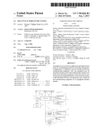
1
Service Repair Guide Classic Series 2003-2010 Common Operating Concerns •Heat pump not turning on, no power/Unit not heating pool water.........................................P6 •Water is leaking from heat pump…………………………………….P7 •Ice build up…………………….……P8 •Time expectations for heating your pool………………………………P8 •Fireman’s switch………………….P9 October 2011 Aqua Comfort Technologies, LLC 2 Identify Heat Pump Code Common Error Codes Flo/FL3- low/no water flow …………………………………………………………P10/P11 FS- defrost cycle………………………………………P8 HP/HP3- high refrigerant pressure…………………………………………...P12/P13 LP/LP3- low refrigerant pressure …………………………………………………………P14-P16 Dpo- defrost sensor open……………………….P17 Dpc- defrost sensor closed……………………..P17 Po- temperature sensor open…………………P18 Pc- temperature sensor closed…………….…P18 PLE/CSE- Eepron memory data loss…………………………………………………………P19 SPI- defective controller…………………………..P19 October 2011 Aqua Comfort Technologies, LLC 3 Problem Solving No display, have power. Control board(Automation)…..…….P20 2. Transformer………………………………….P21 3. Contactor……………………………….......P.22 Fan not running/compressor running 1. Fan capacitor………………………………..P23 2. Fan relay………………………………………P24 3. Fan motor………………………………..P25/26 Fan running/compressor not running/no heat 1. Compressor capacitor…………………..P27 2. Compressor……………………………..P28/29 1. October 2011 Aqua Comfort Technologies, LLC 4 Problem Solving Unit shakes/ makes terrible noise Fan blade………………………………………P30 2. Fan motor………………………………..P25/26 1. 1. Water leak/Rattling Noise when heat pump is off Water header assembly…………………P31 • Parts Lists…………………………………..32-35 October 2011 Aqua Comfort Technologies, LLC 5 Concerns Answered Unit not turning on. When the heat pump doesn’t have a display and will not turn on, the breaker and fuses outside of the heat pump are the most likely cause of the issue. If there is power going into the unit then please turn to page 21 to continue with diagnosing the problem. October 2011 Heat Pump not heating When a new heat pump is installed, the most common service call is the “not heating call.” This is due to lack of run time in most cases, when the heat pump starts up in the beginning of the season it needs time to heat the pool when the weather is cool, if the time clock is prohibiting run time then the pool will not heat. Aqua Comfort Technologies, LLC 6 Concerns Answered Water is leaking from Heat Pump. A very common concern on a new heat pump install is that there is water leaking from the unit. In a majority of calls that water is leaking out of the heat pump, condensation is the cause and there are 2 very easy methods to prove water is not leaking out of the pool. 1) take a chlorine test strip and stick it the water leaking out of the heat pump, no chlorine, no leak. 2) turn the heat pump off and leave the filter running, if the water dries up, then it was condensation. Remember that even when the heat pump is off water still runs through the heat exchanger. Do you have an older heat pump with a leak, see page 31. October 2011 Aqua Comfort Technologies, LLC 7 Concerned Answered Ice build up/FS code At 55 degrees or lower it is possible to see significant ice build up on a heat pump. The machine is designed to keep running (possibly for a couple of hours) so that the heat pump is spending more time heating your pool. When the heat pump reaches its limit of ice build up, it will kick into defrost mode to melt the ice, its around a 10 minute process, then it will start heating the pool again. FS is a code that will blink on the control panel during this process. October 2011 Heating Expectations Every pool is unique, size, shape, location, time of year and size of heat pump are all factors which will affect how fast a pool heat pump will heat the water. For example a 20’ by 40’pool in NJ will take approximately 2-4 days to go from 60 degree water to 85 degrees depending on the outside weather in early May. Remember that a heat pump is designed to provide warm water every day of the week at a low cost, use the pool every day of the summer and get the most value out of the investment. Aqua Comfort Technologies, LLC 8 Concerns Answered Fireman’s switch On Aqua Comfort heat pumps there is no need for a fireman’s switch. There are several safety controls that prevent the heat pump from ever over heating. 1) there is a flow switch that will disengage the compressor when no water is running though, 2) there is a high pressure switch that will turn the heat pump off if refrigerant pressure exceed capacity and 3) the compressor will shut off on thermal overload if the first two safety measures were not effective. If there is a permit issue please contact your sales representative or our main office for assistance. October 2011 Aqua Comfort Technologies, LLC 9 Common Error Codes and Repairs Flo- This code will appear on a heat pump every time the filter is shut off. The heat pump is letting you know that it is not running because no water is going through the system. If the filter pump is running and this code is flashing then the first thing to do is make sure that the filter was recently cleaned/back washed so that proper water flow is reaching the heat pump. Next make sure no by-pass is allowing water to flow around the heat pump’s plumbing, most by-passes consist of 3-way valves and adjusting them to the correct position will allow the heat pump to run properly. Finally, if a heat pump is getting the water flow it needs then it is time to adjust the flow switch or replace it. A FL3 code is letting you know that something is wrong with the flow switch. Continued page 11. October 2011 Aqua Comfort Technologies, LLC 10 Flow Switch 100-210 Replace The flow switch can be found attached to the water manifold. To replace it , turn breaker off, remove the two white/black wires from the top and unthread from the water header assembly. Adjust The flow switch can be adjusted by turning the black dial you see in the middle of it, right to increase PSI needed to activate it or Left to lower the PSI. There is a lock in the back of the switch that needs to be slid up in order to adjust pressure. October 2011 Aqua Comfort Technologies, LLC 11 HP – high refrigerant pressure. - This code is most commonly mistaken as high water pressure but actually refers to the refrigerant pressure inside the heat pump. Poor water flow can sometimes trigger a HP code, this means that the heat pump is creating heat but there is not enough water going though the machine to carry the heat out into the pool. Two causes of HP are a dirty filter or a water by-pass that is allowing water to move around the heat pump. HP can also be a result of a low ground installation. If a pool is installed where the water level in the pool is higher then the plumbing on the heat pump, pressure will constantly be applied to the flow switch and the heat pump will try and run, after 3 tries it will cut off on HP3 until reset manually. An adjustment to the flow switch as described on page 13 will resolve this problem. If none of the above describes your HP situation then the next step will be to replace the high pressure switch. Continued page 13. October 2011 Aqua Comfort Technologies, LLC 12 High Pressure Switch 100-207 - R22 100-207A – 410A Replacing the High Pressure Switch On this model heat pump the pressure switches are screwed onto a schrader valve. When removing the old switch some refrigerant will escape, be sure to complete the removal as fast as possible to prevent too much refrigerant from releasing and freezing your hands. After installing the new HP switch use a soapy water spray to test the switch for any leaks. Wiring- Follow the wires from the switch into the control box, disconnect the old wires from the control box and replace with the new ones. October 2011 Aqua Comfort Technologies, LLC 13 LP- low refrigerant pressure.- This means that the heat pump has shut down because the LP switch circuit has been opened. Weather related LP codes are most common in the beginning and end of a swim season when the temperature is in the 40 degree range and the temperature of the pool water is below 60 degrees. In this case the heat pump needs warmer temperatures to operate. Another cause of low pressure can be a dirty evaporator coil, if you cannot see into you machine through the coil around the side and back, it should be cleaned with a garden hose. October 2011 Aqua Comfort Technologies, LLC 14 LP- continued. First, reset the machine, if the code immediately appears after it turns on, check the refrigerant to confirm it hasn’t leaked out. If there isn’t any pressure in the machine it will need to be leak tested, if there is water coming out of the schrader valve then please contact our main office. If there is refrigerant in the machine, or it does try and turn on then the next step will be to confirm that the fan motor/capacitor/relay are functional, if for any reason the fan doesn’t come on and the compressor does, one of those three components are the cause of the LP3 lockout. October 2011 Aqua Comfort Technologies, LLC 15 Low Pressure Switch 100-207 - R22 100-207A – 410A Replacing the Low Pressure Switch On this model heat pump the pressure switches are screwed onto a schrader valve. When removing the old switch some refrigerant will escape, be sure to complete the removal as fast as possible to prevent too much refrigerant from releasing and freezing your hands. After installing the new LP switch use a soapy water spray to test the switch for any leaks. Wiring- Follow the wires from the switch into the control box, disconnect the old wires from the control board and replace with the new ones. October 2011 Aqua Comfort Technologies, LLC 16 Defrost Sensor 100-202D Do/DC error codes the defrost sensor has either a closed or open circuit, the only way to fix this error is to replace the defrost sensor Replacing the defrost sensor – First locate the defrost sensor on the suction line in the front bottom section of the heat pump. It is covered by a black insulation tape that will need to be removed so that the clamp underneath can be loosened to remove and install the new sensor. The wiring can be followed back into the control box where the wires connect to the control board. October 2011 Aqua Comfort Technologies, LLC 17 Temperature Sensor 100-202D Po/Pc error codes the temperature sensor has either a closed or open circuit, the only way to fix this error is to replace the temperature sensor Replacing the temperature sensor – in all models the temp sensor is located in a dry well screwed into the water header assembly. To remove the sensor, peal back the black foam/tape and cut the zip tie. The wiring can be followed back into the control box where it connects to the control board. Note: if your sensor has a copper tip and is corroded make sure that the temperature well is dry, if there is water inside it, there a possibility that it is leaking and needs to be replaced. October 2011 Aqua Comfort Technologies, LLC 18 PLE/CSE – eepron memory data loss. SPI – defective controller. PLE/CSE – eepron memory data loss If the PLE or CSE error message appears, hold down the hand key until the error message disappears( approx 4 seconds ). The control will be reinitiated to factory default. Re-enter the Pool/Spa set points October 2011 SPI – defective controller Remove power and re-start, If error is still present, replace control Aqua Comfort Technologies, LLC 19 Control Board 100-202A Viconics Control Board Built-to-Last Control Board Replace- On both control boards, remove the screws that hold the board to the control box and screw the replacement board in place. Then remove the wires on the old board one at a time and connect them to the new board to insure the wires are correctly attached. The primary difference between the two boards is that the Viconics board has the fan relay attached to the back, if you are substituting it with a Built-to Last make sure that there is a fan relay kit with the board. Automation – On the Viconics control board the pool temperature must be set to OFF and the spa to 104 degrees. The red wire at the top of the board must be cut and the low voltage wires must be connected to terminals 18 and 19. On the Built-to-Last control board the low voltage wires need to be connected to the terminals P/S. October 2011 Aqua Comfort Technologies, LLC 20 Transformer 100-223 Replace First remove the white, blue and yellow wires that attach to the control board. Then use your volt meter to test voltage from the transformer. The readings should be as follows: White- Blue= 12V White- Yellow= 12V Blue- Yellow= 24V If you have voltage reading that are a little higher than above your transformer is still working properly. If there is any reading that equals zero than the transformer needs to be replaced. To replace leave the yellow, white and blue wires disconnected, follow the black and orange wires to the contactor and disconnect them. Unscrew the transformer from the header plate and install the new part, reinstalling the wires at the same connection points that the previous wires were disconnected. October 2011 Aqua Comfort Technologies, LLC 21 Contactor 13P004A03 The contactor is commonly associated with compressor and not heating issues. If a heat pump seems to be fully functional but the pool is not heating check all wire connections on the contactor, if there are burnt wires or terminals on the contactor, repair the wires and replace the contactor. No visible damage, open the front of the contact to look for signs of damage. Turn the machine on and let it run, check to see if the contactor is pulling in after the time delay(1-5minutes). October 2011 There are many wires on a contactor , when changing it out it is best to remove one at a time and connect them to the new piece so that they don’t get mixed up. Then remove the old contactor from the control box and mount the new contactor. Aqua Comfort Technologies, LLC 22 Fan Capacitor 16P002D06 The fan capacitor is the first part to check when the fan motor is not running properly. The fan capacitor pictured to the right has 10 micro fahrens and 370 volts. When replacing a capacitor always check to make sure that the specifications match. Safety When removing an old capacitor it is important to ground the voltage after the breaker has been turned off. This can be accomplished by removing the fan wires from the top and touching a screw driver across the top and to the back of the control box. Once the voltage has leaked then you can either test for micro fahrens with a MFD tester or replace the capacitor. October 2011 Aqua Comfort Technologies, LLC 23 Fan Relay 100-234 After checking the fan capacitor, the fan relay is the next step in resolving any fan issues that could be affecting the heat pump. A fan relay can cause a fan motor to run all of the time, not run at all or run in reverse. If the fan is running non stop or in reverse, the fan relay will definitely need to be replaced. If the fan will not run, remove the white wire from the relay and attach it to the bottom left of the contactor. Turn the machine on and if the fan runs, the relay needs to be replaced, if the fan still isn’t running, the motor will need to be replaced. October 2011 Aqua Comfort Technologies, LLC 24 Fan Motor 100-200 ½ horse 300-200 ¼ horse If the fan motor is not running or runs for a short period of time then shuts down and the capacitor and fan relay were checked, the motor will need to be replaced. First unscrew the fan grate that the fan motor is mounted to, then gently flip the grate towards the front of the heat pump. Set the grate down on the edge of top cover, use a crescent wrench to loosen the hex bolt on the golden hub slide the fan blade off. Next remove the black and white wires from the relay/contactor or control board, the two brown wires from the capacitor and the green wire from the back of the control box. The wires need to be pulled through the back of the control box and through the plastic mould where the fan is located. (Next Page) October 2011 Aqua Comfort Technologies, LLC 25 Fan Motor (Continued) After the wires have been pulled through, take the fan motor/grate assembly and place it on the ground. Remove the four hex nuts that hold the fan motor to the grate. Place the new motor on the grate and attach the hex nuts, do not over tighten. Place the grate back on the top of the heat pump and run the wires back to the control box. October 2011 Aqua Comfort Technologies, LLC 26 Compressor Capacitor See Parts List The compressor capacitor is the first part to check when your compressor is not running properly. The compressor capacitor pictured to the right has 50 micro fahrens and 370 volts. When replacing a capacitor always check to make sure that the specifications match. Safety When removing an old capacitor it is important to ground the voltage after the breaker has been turned off. This can be accomplished by removing the compressor wires from the top and touching a screw driver across the top and to the back of the control box. Once the voltage has leaked then you can either test for micro fahrens with a MFD tester or replace the capacitor. October 2011 Aqua Comfort Technologies, LLC 27 Checking a Compressor for Grounded Winding With the power to the heater turned off remove the cap from the compressor terminals and disconnect the wires. Then use a screw driver to scrape some of the paint off the side of the compressor which will expose a shiny steel wall. This will offer the best grounding surface. Using a continuity meter test each of the compressor terminals S,R and C separately to the grounding point. If the meter rings out to ground then the compressor is grounded. October 2011 Aqua Comfort Technologies, LLC 28 How to Test the Windings on a Compressor Turn the power off and remove the cap from the compressor and remove the wires from the compressor. 2. Use an ohm meter, by placing the leads on S and R, record the ohm reading. Repeat the process for R and C, C and S. Record the findings. 3. Example of a recording. (R+C)+(S+C)=(R+S) .4 + 1.6 = 2 The result of adding (R+C) to (S+C) should always equal (R+S). If it shows correct ohms across (R+S) but show open across (R+C) or(S+C) it is An additional indicator will be that the compressor will be very possible the internal hot to the touch. The compressor will need time to cool down overload has tripped. and the overload switch will have to close before the compressor 1. will work.(you can not manually close the switch) If a test results in an open winding (OL) the compressor will not turn on. October 2011 Aqua Comfort Technologies, LLC 29 Replacing a Fan Blade 100-201 or 400-003 There are two common reasons that a fan blade might need to be replaced. 1) The heat pump shakes, meaning that the fan blade is unbalanced or it is hitting against the shroud. 2) The golden hub that attaches the blade to the shaft of the fan has come loose causing a loud screeching noise. How to Replace First unscrew the fan grate that the fan motor is mounted to, then gently flip the grate towards the front of the heat pump. Set the grate down on the edge of top cover, use a crescent wrench to loosen the hex bolt on the golden hub. Slide the fan blade off and replace with the new blade. Make sure the new blade is secure to prevent any damage to the inside of the heat pump. October 2011 Aqua Comfort Technologies, LLC 30 This part is found in the back of the heat pump, it makes the connection between the outside water supply/return and the heat exchanger. There are 2 reasons that this part could need to be replaced, 1) manifold is cracked and leaking due to freeze damage or 2) the check valve inside has been damaged and is making a loud rattling sound. Water Manifold See Page 35 for Sizing To replace disconnect the unions on the outside of the heat pump, then remove the clamps on the pressure hoses leading to the heat exchanger. Unthread flow switch and remove temperature sensor. After everything is disconnected the best way to get the old manifold out of the machine is to cut it out with a rope saw, if your going to use a reciprocating saw be very careful not to hit the aluminum coil. When installing the new manifold some assembly (inside the heat pump) is required, place the large piece of the manifold in first then continue with the smaller attachments, you will need pipe cleaner and cement. October 2011 Aqua Comfort Technologies, LLC 31 Parts List 100-001B 100-001C 100-002B 100-002C 100-003B 100-003C 100-004 100-046 100-100S 100-100SJ 100-103 100-109 100-109A 100-110 100-116 100-117 100-118 100-127 100-133 100-200 100-201 100-202A 100-202C 100-202D 100-203 October 2011 Cabinet Base 100-B Black Cabinet Base 100-C Cobblestone Cabinet Top, 200-B Black Cabinet Top 200-C Cobblestone Cabinet Front 300-B Black Cabinet Front 300-C Cobblestone BF106F - Coil Guard 225112 - Fan Guard 24" (mdl. 100/110/125) HLM068T1LP6 Scoll Compressor R-22 (AC125) HLH068T1LP6 Scroll Compressor R-410A (AC150) Titanium Condensor,Specify 125/150 model GT62571 - Expansion Valve R-22 (100/110/125) ERZE-8-GA, Expansion Valve R410A (75-150) 5320-1703 - Strainer R-22 CD-338-2 - Shrader Valve Body CD2245B - Shrader Valve Cap CD4450B - Shrader Valve Core Copper Drier, R410a (75-150) # 92133 Compressor Wire set F48W40D56 - 1/2 HP Fan Motor (100/110/125/150) 61221201 -24" Fan Blade (100/110/125/150) Built to Last -Control Board Built to Last -Control Board, H/C Hybrid Interchangable temp. sensor, B.T.L. / Viconics Compressor capacitor - 50MFD, 440VAC Trane 673, (125) Aqua Comfort Technologies, LLC 32 Parts List Continued 700-203 16P002D06 13P004A03 100-206 100-206A 100-207 100-207A 100-210 100-223 100-228 100-231 100-232 100-233 A 100-233 B 100-234 100-500 100-501 200-100S 200-100SJ 200-103 200-203 200-204 300-100S 300-100SJ 300-103 300-200 October 2011 Compressor capacitor - 80MFD, 370VAC SCROLL 68 (150) Fan capacitor 10MFD, 370VAC, 1/2 h.p. (100/110/125/150) Contactor 2 pole, 40 Amp, 24v (75/100/110/125150) HS200-61-0001 - High Pressure Switch, R22 HS200-61-0005- High Press. Switch, R410A HS200-61-0002 - Low Pressure Switch, R22 HS200-61-0006 - Low Press. Switch, R410A 3903 - Water Pressure Switch Transformer 12/24v Reversing Valve Heat Cool Transformer, 24V 1/2 Copper Check Valve MS-8 (H/C) Interchangable temperature sensor for AM7825 H/C Heat/Cool Switch and Cover Fan Relay Heat/Cool Copper Reversing Valve Assy Heat/Cool Copper TXV Assy HRM051U1LP6 Scroll Compressor, R22 (95/110) HRH051U1LP6 Scroll Compressor, R410A (125) Titanium Condensor (110) Comp. Capacitor Trane: 55MFD, 370VAC (110) Comp. Capacitor 051 Scroll: 70MFD, 370VAC (125) HRM038U1LP6 Scroll Comp., R22 (100) HRHO38U1LP6 Scroll Comp., 410A (110) Titanium Condensor (100) 1/4 H.P. Fan Motor (55) Aqua Comfort Technologies, LLC 33 Parts List Continued 300-202 300-203 300-204 400-001C 400-002C 400-003C 400-103 400-002 400-003 400-100S 400-100SJ 600-005 600-200 600-259A 600-259B 600-261A 600-261B 600-261C 600-261D 600-265A 600-265B 600-265C 600-265D RDPKIT October 2011 Comp. Capacitor 038 Scroll: 60MFD, 370VAC (110) Capacitor Comp., 45MFD, 370VAC (mdl. 55/75/100) Capacitor Fan- 5MFD, 370VAC (mdl. 55/75 only) Cabinet Top (55) 100-C Cobblestone Cabinet Base (55) 200-C Cobblestone Cabinet Front (55) 300-C Cobblestone Titanium Condensor (55) 20" Fan Guard (mdl. 55) 20" Fan Blade (mdl. 55) HRM031U1LP6 Scroll Comp.,, R22 (55) HRH031U1LP6 Scroll Comp., R410A (75) 990180-000 - Drywell Assy, 5/16 Plastic 457-020 - PVC S-40 Union, 2" SXS (BUNA) Plumbing Kit - 55 CuNi, inlet and outlet Plumbing Kit - 55 Ti,inlet and outlet Plumbing Kit - 125 Plumbing Kit - 110 Plumbing Kit - 100 Plumbing Kit - Old Style 95/125 cross over manifold Conversion Kit 125, CuNi to Titanium (pvc & copper) Conversion Kit 110, CuNi to Titanium (pvc & copper) Conversion Kit 100, CuNi to Titanium (pvc & copper) Conversion Kit 55, CuNi to Titanium (pvc & copper) Dealer Part Kit Aqua Comfort Technologies, LLC 34 Dealer Part Kit RDPKIT (20) (2) (4) (2) (6) (4) (2) (6) (4) 100-202D 100-234 13P004A03 100-200 16P002D06 100-202A 100-210 100-201 600-261A October 2011 Interchangable temp. sensor Fan Relay 2 POLE CONTACTOR 24 VAC-40A F48W40D56 - 1/2 HP Fan Motor CAPACITOR 10 MFD 370 V (Fan capacitor) Built to Last -Control Board 3903 - Water Pressure Switch 61221201 -24" Fan Blade Plumbing Kit - 125 Aqua Comfort Technologies, LLC 35 Please Contact Technical Sales and Service Support Aqua Comfort 520 Highway 17 South, Unit F Surfside Beach, SC 29575 (P) 1-888-475-7443 (F) 1-866-264-0887 [email protected]