1
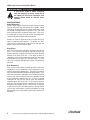
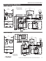
Delfield ™ ® 6000XL & 6100XL Series Reach Ins Service, Installation and Care Manual Please read this manual completely before attempting to install or operate this equipment! Notify carrier of damage! Inspect all components immediately. See page 2. Refrigerators and Freezers ATION M R O F ANT IN T R O P USE IM E R O F E NS! O I T C READ B U STR N I E S E E TH V A S E S PLEA March 2011 6000XL Series Service and Installation Manual Contents Serial Number Information......................................................... 2 Receiving & Inspecting Equipment............................................ 2 Specifications.............................................................................. 3 Installation................................................................................... 4 Door Reversal Procedures.......................................................... 5 Leg & Caster Installation............................................................. 5 Operation..................................................................................... 6 Maintenance.............................................................................7-8 Wiring Diagrams....................................................................9-13 Serial Number Information The serial number of all self-contained 6000XL Series refrigerators and freezers is located above the door under the shroud. Always have the serial number of your unit available when calling for parts or service. A complete list of authorized Delfield parts depots is available at www.delfield.com. This manual covers standard units only. If you have a custom unit, consult the customer service department at the number listed below. Refrigeration Package Diagram................................................14 Replacement Parts...............................................................15-16 Standard Labor Guidelines.......................................................17 Standard Warranties............................................................18-19 ©2011 The Delfield Company. All rights reserved. Reproduction without written permission is prohibited. “Delfield” is a registered trademark of The Delfield Company. Receiving And Inspecting The Equipment Even though most equipment is shipped crated, care should be taken during unloading so the equipment is not damaged while being moved into the building. 1. Visually inspect the exterior of the package and skid or container. Any damage should be noted and reported to the delivering carrier immediately. 2. If damaged, open and inspect the contents with the carrier. 3. In the event that the exterior is not damaged, yet upon opening, there is concealed damage to the equipment notify the carrier. Notification should be made verbally as well as in written form. 4. Request an inspection by the shipping company of the damaged equipment. This should be done within 10 days from receipt of the equipment. 5. Be certain to check the compressor compartment housing and visually inspect the refrigeration package. Be sure lines are secure and base is still intact. 6. Freight carriers can supply the necessary damage forms upon request. 7. Retain all crating material until an inspection has been made or waived. NOTE: Upon powering unit, there could be up to a 10 minute delay before unit begins to cool. Delfield ™ 2 For customer service, call (800) 733-8829, (800) 733-8821, Fax (888) 779-2040, www.delfield.com ® 6000XL Series Service and Installation Manual Specifications Voltage Amps Storage Capacity FT3 Shelf Capacity FT2 H.P. BTU/HR Evap. Temp R-404A Charge Oz. Shipping Weight Nema Plug 6025XL-SH,S 115 6.0 20.0 15.1 1/4 2092 20˚F 12.5 274lbs/124kg 5-15p 6025XL-G,GH 115 6.0 20.0 15.1 1/4 2092 20˚F 12.5 338lbs/153kg 5-15p 6051XL-SH,S 115 8.0 43.5 33.2 1/3 2488 20˚F 12.5 454lbs/206kg 5-15p 6051XL-G,GH 115 8.0 43.5 33.2 1/3 2488 20˚F 12.5 548lbs/249kg 5-15p 6076XL-SH,S 115 16.0 66.5 48.3 1/4, 1/3 2092/2488 20˚F 12.5/12.5 622lbs/282kg 5-20p 6076XL-G,GH 115 16.0 66.5 48.3 1/4, 1/3 2092/2488 20˚F 12.5/12.5 774lbs/351kg 5-20p 6125XL-S,SH 115 9.0 20.0 15.1 1/2 2092 -20˚F 12.5 274lbs/124kg 5-15p 6151XL-S,SH 115 12.0 43.5 33.2 3/4 1923 -20˚F 12.5 454lbs/206kg 5-15p 6176XL-S,SH 120/208230 20.0 66.5 48.3 1/2, 3/4 1516/1923 -20˚F 12.5/12.5 622lbs/282kg 14-20P Voltage Amps Storage Capacity FT3 Shelf Capacity FT2 Required BTU/HR Evap. Temp Shipping Weight 6025XLR-SH,S 115 5.0 20.0 15.1 2092 20˚F 274lbs/124kg 6025XLR-G,GH 115 5.0 20.0 15.1 2092 20˚F 338lbs/153kg 6051XLR-SH,S 115 5.0 43.5 33.2 2488 20˚F 454lbs/206kg 6051XLR-G,GH 115 5.0 43.5 33.2 2488 20˚F 548lbs/249kg 6076XLR-SH,S 115 5.0 66.5 48.3 2092/2488 20˚F 622lbs/282kg 6076XLR-G,GH 115 5.0 66.5 48.3 2092/2488 20˚F 774lbs/351kg 6125XLR-S,SH 115 5.0 20.0 15.1 2092 -20˚F 274lbs/124kg 6151XLR-S,SH 115 5.0 43.5 33.2 1923 -20˚F 454lbs/206kg 6176XLR-S,SH 115 5.0 66.5 48.3 1516/1923 -20˚F 622lbs/282kg Model Model Delfield ™ ® For customer service, call (800) 733-8829, (800) 733-8821, Fax (888) 779-2040, www.delfield.com 3 6000XL Series Service and Installation Manual Installation Location Units represented in this manual are intended for indoor use only. Be sure the location chosen has a floor strong enough to support the total weight of the cabinet and contents. A fully loaded 6000XL series can weigh as much as 1500 pounds. Reinforce the floor as necessary to provide for maximum loading. For the most efficient refrigeration, be sure to provide good air circulation inside and out. Inside cabinet: Do not pack refrigerator so full that air cannot circulate. The refrigerated air is discharged at the top rear of the unit. It is important to allow for proper air flow from the top rear to the bottom of the unit. Obstructions to this air flow can cause evaporator coil freeze ups and loss of temperature or overflow of water from the evaporator drain pan. The rear of the unit has molded ribs and the shelves have a rear turn up on them to prevent this. However, bags and other items can still be located to the far rear of the cabinet. There is also a return air diffuser along the top front of the cabinet interior, this also requires proper air circulation. Prevent obstruction by locating large boxes and tall stacks of product to the bottom of the cabinet. Stabilizing Some models are supplied on casters for your convenience, ease of cleaning underneath and for mobility. It is very important, however, that the cabinet be installed in a stable condition with the front wheels locked while in use. Should it become necessary to lay the unit on its side or back for any reason, allow at least 24 hours before start-up so as to allow compressor oil to flow back to the sump. Failure to meet this requirement can cause compressor failure and unit damage. Unit repairs will not be subject to standard unit warranties due to improper installation procedures. Electrical connection Refer to the amperage data on page 3, the serial tag, your local code or the National Electrical Code to be sure the unit is connected to the proper power source. A protected circuit of the correct voltage and amperage must be run for connection of the line cord, or permanent connection to the unit. The thermostat must be turned to OFF and the unit disconnected from the power source whenever performing service, maintenance functions or cleaning the refrigerated area. Outside cabinet: Be sure that the unit has access to ample air. Avoid hot corners and locations near stoves and ovens. It is recommended that the unit be installed no closer than 2” from any wall with at least 12” of clear space above the unit. Avoid exposing glass door units to direct sunlight. Direct sunlight through the glass doors will make the ABS liner fade and become brittle and will greatly reduce refrigeration efficiency. Leveling A level cabinet looks better and will perform better because the doors will line up with the frames properly, the cabinet will not be subject to undue strain and the contents of the cabinet will not move around on the shelves. Use a level to make sure the unit is level from front to back and side to side. Units supplied with legs will have adjustable bullet feet to make the necessary adjustments. If the unit is supplied with casters, no adjustments are available. Ensure the floor where the unit is to be located is level. Delfield ™ 4 For customer service, call (800) 733-8829, (800) 733-8821, Fax (888) 779-2040, www.delfield.com ® 6000XL Series Service and Installation Manual Door Reversal Procedures Standard Edge-Mount Hinge Only for Models Ordered With Re-Hinging Option 1. Open door 90˚ and lift door straight up and off hinges. 2. Remove the metal screw covers on each door-side hinge section by sliding it down and off. 3. Remove two outer screws that mount each hinge to door, loosen the center screw, rotate hinge 180˚, reinstall outer screws and retighten center screw. 4. Remove two screws that mount lock on top of door, turn door up-side-down and remount lock to top of door. 5. Use a 3/16” drill to drill holes in cabinet face frame at the marked hinge locations on the new hinge side. 6. Remove the cabinet hinge screw covers by gently prying them out with a small screwdriver. 7. Remove all three screws from each hinge and mount them to the opposite side of the door opening. 8. Remove the plastic cam from the hinges by pulling straight up, then rotating the cam 180˚ and pushing back into the hinge. 9. Remount the door and check for proper closure and gasket seal. Adjust hinges as needed. Once adjustment is verified, remove the door, reinstall all hinge screw covers and set the door back in place. 10. If plugs are needed to plug old screw holes in cabinet face frame, please contact Delfield Parts Department at (800) 733-8821, extension 12801. 1. Open door 90˚ and lift door straight up and off hinges. 2. Remove the metal screw covers on each door-side hinge section by sliding it down and off. 3. Remove two outer screws that mount each hinge to door, loosen the center screw, rotate hinge 180˚, reinstall outer screws and retighten center screw. 4. Remove two screws that mount lock on top of door, turn door up-side-down and remount lock to top of door. 5. Pry the plugs out of the hinge mounting holes on the side opposite the current hinge locations and set them aside. 6. Remove the cabinet hinge screw covers by gently prying them out with a small screwdriver. 7. Remove all three screws from each hinge and mount them to the opposite side of the door opening. Press the plugs removed in step 5 into the screw holes from the original hinge locations. 8. Remove the plastic cam from the hinges by pulling straight up, then rotating the cam 180˚ and pushing back into the hinge. 9. Remount the door and check for proper closure and gasket seal. Adjust hinges as needed. Once adjustment is verified, remove the door, reinstall all hinge screw covers and set the door back in place. 10. If additional plugs are needed due to loss or damage, please contact Delfield Parts Department at (800) 733-8821, extension 12801. Leg & Caster Installation WARNING Some cabinets may weigh over 1000 lbs (450 kg). Use a lifting device capable of supporting the unit when removing skid or installing legs or casters. To install the legs, or casters refer to Figure 1 and proceed as follows: 1. Remove unit from skid. 2. Raise unit to access leg/caster mounting bolts on bottom of unit. 3. Remove the bolts from the cabinet and use them to attach the legs or casters. All single-section units require that the swivel casters be mounted on the front and rigid casters be mounted on the rear. Delfield ™ Figure 1. Leg or Caster Installation ® For customer service, call (800) 733-8829, (800) 733-8821, Fax (888) 779-2040, www.delfield.com 5 6000XL Series Service and Installation Manual Operation Electronic Temperature Control Operation: The electronic temperature control constantly monitors box temperature as well as evaporator coil temperature to maintain consistent product temperatures. The control also sends temperature readings to the digital temperature display. The control circuits continually self-check and if an error occurs, the digital display will switch from temperature read-out to error read-out, i.e. E 1. Even when an error is displayed, the refrigeration and controls system should continue to function, however not at optimal performance. Whenever the display has an error read-out, Delfield Service should be contacted. At initial start-up or anytime power is disconnected, then reconnected to the unit, the control will delay all operations for a short time (up to 10 minutes.) While in this delay period, the control initializes the control parameters and confirms that the temperature sensors and circuits are operational. The digital temperature display will not display temperature OR errors until the self-check is complete and the control has switched on the evaporator fan motor, compressor and condenser fan motor. IMPORTANT NOTE REGARDING FREEZERS: After initializing, the control will immediately enter a DEFROST mode and the display will read DEF. The compressor and condenser fan as well as the evaporator fan will remain off until initialization defrost is complete. This initial defrost cycle may take up to 15 minutes to complete, at which time the freezing cycle will begin. The display will continue to read DEF for an additional 30 minutes before displaying temperature. Refrigerator: The control is located in the control box in the top of the refrigerator behind the removable louvered panel on the left side. It is factory set at mid-range to maintain about 38˚F (3˚C) box temperature. To adjust for colder temperatures, turn the knob clockwise. For warmer temperatures, turn the knob counter-clockwise. Turn the knob fully counter-clockwise to turn the refrigeration system off. Never turn the knob more than 1 dial number and always allow 8 hours for temperature stabilization before making any additional adjustments. Freezer: The control is located in the control box in the top of the refrigerator behind the removable louvered panel on the left side. It is factory set at mid-range to maintain about -3˚F (-18˚C) box temperature. To adjust for colder temperatures, turn the knob clockwise. For warmer temperatures, turn the knob counter-clockwise. Turn the knob fully counter-clockwise to turn the refrigeration system off. Never turn the knob more than 1 dial number and always allow 8 hours for temperature stabilization before making any additional adjustments. Energy Saver Switch The energy saver switch is a rocker switch located next to the thermostat knob that controls the amount of heat applied to the door perimeter. The normal operating position for this switch is the ON position, providing the least heat. If excessive condensation is observed on the door opening, press the energy saver switch to the OFF position, to increase the amount of heat (red portion of the rocker switch will be visible). Refrigeration & Defrost Cycle Refrigerator: Whenever the refrigerator is plugged in, and the control has completed initializing, the evaporator fans will run continuously and the digital temperature will display box temperature in degrees F. The temperature control will cycle the compressor and condenser fan motor to maintain box temperature at the control setting. Refrigerator Defrost The temperature control also monitors the evaporator temperature and will turn off the compressor and condenser fan motor when needed to allow accumulated frost on the evaporator to clear. During this defrost cycle, the digital temperature display will read dEF. After the defrost cycle is complete, the temperature control will return to a normal cooling cycle, but the display will continue to read dEF until the evaporator returns to normal cooling temperatures (up to 30 minutes). Freezer: Whenever the freezer is plugged in, and the control has completed initializing including the initial defrost cycle (also see Electronic Temperature Control Operation, on this page), the evaporator fans will run continuously. After evaporator coil has reached operational temperature, the digital temperature will display box temperature in degrees F. The temperature control will cycle the compressor and condenser fan motor to maintain box temperature at the control setting. Freezer Automatic Defrost The control also monitors compressor total running time and will enter a defrost cycle after total compressor running time is greater than 4-hours since the last defrost cycle OR if evaporator coil temperature drops below -34˚F (indicating excessive frost on the coil). Freezer Manual Defrost If a manual defrost is desired, simply unplug the unit for several seconds, then plug unit back in. This will cause the control to re-initialize and then enter a defrost cycle. When the control enters the defrost mode, it switches off the evaporator fan motor, compressor and condenser fan motor, and switches on the defrost heater to warm the evaporator coil. Thereby melting all frost accumulated during the previous refrigeration cycle. The digital temperature display will now read dEF. The control will continue the defrost cycle for a MINIMUM of 8 minutes and a MAXIMUM of 30 minutes depending on the amount of frost accumulated on the evaporator coil. After the defrost cycle is complete, the control returns to a normal refrigeration cycle, however the evaporator fan motor will not switch on for 2 minutes AFTER the compressor and condenser fan motor have begun operating. The digital temperature display will continue to read dEF until the evaporator has returned to normal freezing temperatures (up to 30 minutes). Delfield ™ 6 For customer service, call (800) 733-8829, (800) 733-8821, Fax (888) 779-2040, www.delfield.com ® 6000XL Series Service and Installation Manual Maintenance The thermostat must be turned to OFF and the unit disconnected from the power source whenever performing service, maintenance functions or cleaning the refrigerated area. Refrigerators and Freezers The interior and exterior can be cleaned using soap and warm water. If this isn’t sufficient, try ammonia and water or a nonabrasive liquid cleaner. When cleaning the exterior, always rub with the “grain” of the stainless steel to avoid marring the finish. Do not use an abrasive cleaner because it will scratch the stainless steel and plastic and can damage the breaker strips and gaskets. Cleaning the Condenser Coil The condenser coil requires regular cleaning, recommended is every 90 days. In some instances though you may find that there is a large amount of debris and dust or grease accumulated prior to the 90 day time frame. In these cases the condenser coil should be cleaned every 30 days. If the build up on the coil consists of only light dust and debris the condenser coil can be cleaned with a simple brush, heavier dust build up may require a vacuum or even compressed air to blow through the condenser coil. If heavy grease is present there are de-greasing agents available for refrigeration use and specifically for the condenser coils. The condenser coil may require a spray with the de-greasing agent and then blown through with compressed air. Failure to maintain a clean condenser coil can initially cause high temperatures and excessive run times, continuous operation with dirty or clogged condenser coils can result in compressor failures. Neglecting the condenser coil cleaning procedures will void any warranties associated with the compressor or cost to replace the compressor. Never use a high pressure water wash for this cleaning procedure as water can damage the electrical components located near or at the condenser coil. Stainless Steel Care and Cleaning To prevent discoloration or rust on stainless steel several important steps need to be taken. First, we need to understand the properties of stainless steel. Stainless steel contains 70-80% iron which will rust. It also contains 12-30% chromium which forms an invisible passive film over the steels surface which acts as a shield against corrosion. As long as the protective layer is intact, the metal is still stainless. If the film is broken or contaminated, outside elements can begin to breakdown the steel and begin to form rust of discoloration. Proper cleaning of stainless steel requires soft cloths or plastic scouring pads. NEVER USE STEEL PADS, WIRE BRUSHES OR SCRAPERS! Cleaning solutions need to be alkaline based or non-chloride cleaners. Any cleaner containing chlorides will damage the protective film of the stainless steel. Chlorides are also commonly found in hard water, salts, and household and industrial cleaners. If cleaners containing chlorides are used be sure to rinse repeatedly and dry thoroughly upon completion. Routine cleaning of stainless steel can be done with soap and water. Extreme stains or grease should be cleaned with a nonabrasive cleaner and plastic scrub pad. It is always good to rub with the grain of the steel. There are also stainless steel cleaners available which can restore and preserve the finish of the steels protective layer. Early signs of stainless steel breakdown can consist of small pits and cracks. If this has begun, clean thoroughly and start to apply stainless steel cleaners in attempt to restore the passivity of the steel. Never use an acid based cleaning solution! Many food products have an acidic content which can deteriorate the finish. Be sure to clean the stainless steel surfaces of ALL food products. Common items include, tomatoes, peppers and other vegetables. In order to maintain proper refrigeration performance, the condenser fins must be cleaned of dust, dirt and grease regularly. It is recommended that this be done at least every three months. If conditions are such that the condenser is totally blocked in three months, the frequency of cleaning should be increased. Clean the condenser with a vacuum cleaner or stiff brush. If extremely dirty, a commercially available condenser cleaner may be required. Delfield ™ ® For customer service, call (800) 733-8829, (800) 733-8821, Fax (888) 779-2040, www.delfield.com 7 6000XL Series Service and Installation Manual Maintenance, continued If your freezer seems to vibrate excessively when the compressor is running, loosen (but do not remove) the bolts on the compressor. Semi hermetic models should be loosened before operating. BASIC MAINTENANCE Gasket Maintenance Gaskets require regular cleaning to prevent mold and mildew build up and also to keep the elasticity of the gasket. Gasket cleaning can be done with the use of warm soapy water. Avoid full strength cleaning products on gaskets as this can cause them to become brittle and prevent proper seals. Also, never use sharp tools or knives to scrape or clean the gasket which could possibly tear the gasket and rip the bellows. Gaskets can easily be replaced and do not require the use of tools or authorized service persons. The gaskets are “Dart” style and can be pulled out of the grove in the door and new gaskets can be “pressed” back into place. Doors/Hinges Over time and with heavy use doors the hinges may become loose. If it is noticed that the door is beginning to sag, it may become necessary to tighten the screws that mount the hinge brackets to the frame of the unit. If the doors are loose or sagging this can cause the hinge to pull out of the frame which may damage both the doors and the door hinges. In some cases this can require qualified service agents or maintenance personnel. Drain Maintenance Each unit has a drain located inside the unit which removes the condensation from the evaporator coil and evaporates it at an external condensate evaporator pan. Each drain can become loose or disconnected from moving or bumping the drain. If you notice excessive water accumulation on the inside of the unit be sure the drain tube is connected from the evaporator housing to the condensate evaporator drain pan. If water is collected underneath the unit you may want to check the condensate evaporator drain tube to be sure it is still located inside the drain pan. The leveling of the unit is important as the units are designed to drain properly when on a level surface, if your floor is not level this can also cause drain problems. Be sure all drain lines are free of obstructions, typically food product is found blocking drain lines causing water to back up and overflow the drain pans. Delfield ™ 8 For customer service, call (800) 733-8829, (800) 733-8821, Fax (888) 779-2040, www.delfield.com ® 6000XL Series Service and Installation Manual Wiring Diagrams: Refrigerators 6025XL-S, 6025XL-SH L1 NOTES: 1) USE COPPER CONDUCTORS ONLY 2) THIS UNIT MUST BE GROUNDED 3) UNIT SHOWN WITH COMPRESSOR RUNNING AND DOORS CLOSED N LINE VOLTAGE 115/60/1 SEE NAMEPLATE FOR MAXIMUM FUSE SIZE EVAPORATOR HOUSING EVAP FAN MOTOR M PLUG CONTROL CIRCUIT N 5 C COMPRESSOR RELAY BLUE M 1 INCANDESCENT LIGHT COMPRESSOR W WITH BLUE STRIPES W 1.1,2,3 2.1,2,3 3.1,2,3 M ENERGY SAVER SWITCH WIRE NUT W CONTROL BOX CONDENSER FAN MOTOR CABINET AIR SENSOR EVAP COIL SENSOR LED DISPLAY (IF USED) W EVAP COIL SENSOR L 3 CABINET AIR SENSOR TEMPERATURE CONTROL W SPLICE BLK BLK POWER BOX W START RELAY BLK M 10 EVAPORATOR FAN MOTOR 12 RED C L L H N F 1 2 3 4 5 6 TEMPERATURE CONTROL BLK M N RU ING ND DOOR FRAME HEATER WI ENERGY SAVER SWITCH START CAPACITOR 11 BLK CONDENSER FAN RT G STA INDIN 13 W COMPRESSOR GROUND 14 MOTOR PROTECTOR 1.1,2,3 2.1,2,3 3.1,2,3 DOOR SWITCH INCANDESCENT LIGHT BLK BLK W LED DISPLAY (IF USED) DOOR HINGE SWITCH COMPRESSOR FRAME HEATERS 6025XL-G, 6025XL-GH BLK L1 FLUORESCENT LIGHT BALLAST N LINE VOLTAGE 115/60/1 SEE NAMEPLATE FOR MAXIMUM FUSE SIZE M PLUG N FLUORESCENT LAMP ASSEMBLY 5 W C COMPRESSOR RELAY EVAP FAN MOTOR BLK M 1 BLUE W EVAP COIL SENSOR CONTROL CIRCUIT EVAPORATOR HOUSING CABINET AIR SENSOR L BLUE FLUORESCENT LAMP TEMPERATURE CONTROL 3 RED FLUORESCENT LAMP SWITCH COMPRESSOR 1.1,2,3 2.1,2,3 3.1,2,3 BLK W CONDENSER FAN MOTOR CABINET AIR SENSOR EVAP COIL SENSOR LED DISPLAY (IF USED) M ENERGY SAVER SWITCH W WITH BLUE STRIPES WIRE NUT W CONTROL BOX W SPLICE BLK BLK M POWER BOX W EVAPORATOR FAN MOTOR START RELAY BLK 10 START CAPACITOR 11 BLK 12 C L L H N F 1 2 3 4 5 6 TEMPERATURE CONTROL M FLUORESCENT LAMP BALLAST FLUORESCENT LAMP SWITCH RT G STA INDIN 13 W 14 COMPRESSOR GROUND MOTOR PROTECTOR 1.1,2,3 2.1,2,3 3.1,2,3 FLUORESCENT LAMP Delfield ™ CONDENSER FAN N RU ING D DOOR FRAME HEATER WIN ENERGY SAVER SWITCH BLK NOTES: 1) USE COPPER CONDUCTORS ONLY 2) THIS UNIT MUST BE GROUNDED 3) UNIT SHOWN WITH COMPRESSOR RUNNING AND DOORS CLOSED BLK W LED DISPLAY (IF USED) COMPRESSOR FRAME HEATERS ® For customer service, call (800) 733-8829, (800) 733-8821, Fax (888) 779-2040, www.delfield.com 9 6000XL Series Service and Installation Manual Wiring Diagrams: Refrigerators 6051XL-S, 6051XL-SH 6051XL-G, 6051XL-GH Delfield ™ 10 For customer service, call (800) 733-8829, (800) 733-8821, Fax (888) 779-2040, www.delfield.com ® 6000XL Series Service and Installation Manual Wiring Diagrams: Refrigerators 6076XL-S, 6076XL-SH 6076XL-G, 6076XL-GH Delfield ™ ® For customer service, call (800) 733-8829, (800) 733-8821, Fax (888) 779-2040, www.delfield.com 11 6000XL Series Service and Installation Manual Wiring Diagrams: Freezers 6125XL-S, 6125XL-SH L1 N LINE VOLTAGE 115/60/1 SEE NAMEPLATE FOR MAXIMUM FUSE SIZE NOTES: 1) USE COPPER CONDUCTORS ONLY 2) THIS UNIT MUST BE GROUNDED 3) UNIT SHOWN WITH COMPRESSOR RUNNING AND DOORS CLOSED EVAPORATOR HOUSING EVAP FAN MOTOR Y N CONTROL CIRCUIT PLUG 5 M DEFROST HEATER EVAP COIL SENSOR BLUE F 6 FAN RELAY CABINET AIR SENSOR L 3 HIGH TEMP LIMIT SWITCH M TEMPERATURE CONTROL EVAPORATOR FAN INCANDESCENT LIGHT H 4 HEATER RELAY DEFROST HEATER C M W WITH BLUE STRIPES W CONTROL BOX 1 COMPRESSOR RELAY ENERGY SAVER SWITCH COMPRESSOR WIRE NUT W P 1.1,2,3 2.1,2,3 3.1,2,3 W M LED DISPLAY (IF USED) W SPLICE BLK CONDENSOR FAN EVAP COIL SENSOR CABINET AIR SENSOR POWER BOX GREY BLK START CAPACITOR W 10 BLK W RED ENERGY SAVER SWITCH C L L H N F 1 2 3 4 5 6 TEMPERATURE CONTROL BLK DOOR FRAME HEATER W 13 14 WINDING PROTECTOR CONDENSER FAN M 1.1,2,3 2.1,2,3 3.1,2,3 DOOR SWITCH 11 12 RUN WINDIN G INCANDESCENT LIGHT START G WINDIN BLK DOOR HINGE SWITCH BLK LED DISPLAY (IF USED) W COMPRESSOR FRAME HEATERS 6125XL-G, 6125XL-GH L1 N LINE VOLTAGE 115/60/1 SEE NAMEPLATE FOR MAXIMUM FUSE SIZE EVAPORATOR HOUSING EVAP FAN MOTOR BLK FLUORESCENT LIGHT BALLAST HIGH TEMP LIMIT SWITCH M TEMPERATURE CONTROL N F FAN RELAY Y FLUORESCENT LAMP 5 6 DEFROST HEATER BLUE M FLUORESCENT LAMP ASSEMBLY BLK EVAPORATOR FAN PLUG EVAP COIL SENSOR CONTROL CIRCUIT BLUE CABINET AIR SENSOR L 3 RED FLUORESCENT LAMP SWITCH W H HEATER RELAY 4 C COMPRESSOR RELAY DEFROST HEATER W M 1 CONTROL BOX COMPRESSOR 1.1,2,3 2.1,2,3 3.1,2,3 W ENERGY SAVER SWITCH W WITH BLUE STRIPES WIRE NUT W P M LED DISPLAY (IF USED) W CABINET AIR SENSOR EVAP COIL SENSOR CONDENSOR FAN SPLICE BLK BLK GREY POWER BOX BLK START CAPACITOR W 10 BLK W ENERGY SAVER SWITCH DOOR FRAME HEATER FLUORESCENT LAMP BALLAST C L L H N F 1 2 3 4 5 6 TEMPERATURE CONTROL 14 M START NG WINDI BLK BLK W LED DISPLAY (IF USED) FRAME HEATERS 12 WINDING PROTECTOR CONDENSER FAN RUN WINDI NG FLUORESCENT LAMP NOTES: 1) USE COPPER CONDUCTORS ONLY 2) THIS UNIT MUST BE GROUNDED 3) UNIT SHOWN WITH COMPRESSOR RUNNING AND DOORS CLOSED 13 12 W 1.1,2,3 2.1,2,3 3.1,2,3 FLUORESCENT LAMP SWITCH 11 For customer service, call (800) 733-8829, (800) 733-8821, Fax (888) 779-2040, www.delfield.com COMPRESSOR Delfield ™ ® 6000XL Series Service and Installation Manual Wiring Diagrams: Freezers 6151XL-S, 6151XL-SH L1 N LINE VOLTAGE 115/60/1 SEE NAMEPLATE FOR MAXIMUM FUSE SIZE NOTES: 1) USE COPPER CONDUCTORS ONLY 2) THIS UNIT MUST BE GROUNDED 3) UNIT SHOWN WITH COMPRESSOR RUNNING AND DOORS CLOSED EVAPORATOR HOUSING EVAP FAN MOTOR Y N BLUE F FAN RELAY PLUG 5 M 6 DEFROST HEATER EVAP COIL SENSOR CONTROL CIRCUIT 3 CABINET AIR SENSOR L HIGH TEMP LIMIT SWITCH M TEMPERATURE CONTROL EVAPORATOR FAN INCANDESCENT LIGHT H HEATER RELAY 4 DEFROST HEATER C COMPRESSOR RELAY M CONTROL BOX 1 COMPRESSOR W ENERGY SAVER SWITCH W WITH BLUE STRIPES WIRE NUT W P 1.1,2,3 2.1,2,3 3.1,2,3 W M SPLICE BLK CONDENSOR FAN W CABINET AIR SENSOR EVAP COIL SENSOR LED DISPLAY (IF USED) W POWER BOX GREY BLK MOTOR PROTECTOR MAIN WINDING C BLK RUN CAPACITOR W RED ENERGY SAVER SWITCH BLK DOOR FRAME HEATERS C L L H N F 1 2 3 4 5 6 TEMPERATURE CONTROL W S INCANDESCENT LIGHT DOOR HINGE SWITCHES BLK DOOR FRAME HEATERS W LED DISPLAY (IF USED) BLK 2 4 1 START WINDING CONDENSER FAN 1.1,2,3 2.1,2,3 3.1,2,3 DOOR SWITCHES R M 5 1 1 2 2 N N L L START CAPACITOR COMPRESSOR 6176XL-S, 6176XL-SH Delfield ™ ® For customer service, call (800) 733-8829, (800) 733-8821, Fax (888) 779-2040, www.delfield.com 13 6000XL Series Service and Installation Manual Refrigeration Package Diagram 17 16 4 7 15 18 5 12 6 14 11 9 1 3 8 21 13 9 14 11 7 1 15 16 4 5 6 17 21 19 20 3 2 18 Delfield ™ 14 For customer service, call (800) 733-8829, (800) 733-8821, Fax (888) 779-2040, www.delfield.com ® 6000XL Series Service and Installation Manual Refrigeration Package - Replacement Parts Refrigerator - 1 section & 3 section left package Item Number Part Number 1 2 (kit) 3 4 5 6 7 8 9 11 12 13 14 15 15 16 16 17 17 18 3516437 2194782KT 2190154 2184181 2162715 3517390 3516588 3516205 3516427 127-C33-0036 2162717 3516432 2160019 3526999 220V/50Hz Part# 2194988KT 2162719 2192720 3527013 3516444 117U6002 2194787 117U5015 3516322 1702795 3516041 Freezer- 1 section & 3 section left package Description Coil, evaporator Control, ETC1, Kit Switch, energy saver Cord, power Motor, fan, evaporator Fan blade, evaporator Valve, refrigerant, TXV Clip, TXV bulb mounting Coil, condenser Shroud, condenser fan Motor, fan, condenser, 9W Fan blade, condenser Guard, condenser fan Compressor Compressor, 50Hz - NL7CUX Relay & overload, compressor 50Hz Relay and overload, Danfoss p/n Capacitor, compressor start, 280MFD 50Hz Capacitor, start, 80MFD, Danfoss p/n Filter-drier, refrigerant Condensate pan Solenoid valve, used on remote units Refrigerator - 2 section & 3 section right package Item Number Part Number 1 2 (kit) 3 4 5 6 7 8 9 11 12 13 14 15 15 16 16 17 17 18 3516437 2194782KT 2190154 2184181 2162715 3517390 3516588 3516205 3516427 127-C33-0030 2162716 3516433 2160019 3527000 220V/50Hz Part# 2194988KT 2192719 2162721 3527012 3516438 117U6003 2194788 117U5015 3516322 1702795 3516041 Delfield ™ Item Number 1 2 (kit) 3 4 5 6 7 8 9 11 12 13 14 15 15 16 16 17 17 18 19 20 21 Part Number 3516436 2194783KT 2194959 2184181 2162715 3517390 3516588 3516205 3516427 127-C33-0036 2162717 3516432 2160019 3527001 220V/50Hz Part# 2194964KT 2194183 2162719 2162720 3527011 3516441 117U6019 2194789 117U5017 3516322 2194785 9321629 2194953 1702795 3516041 2194967 Description Coil, evaporator Control, ETC1, Kit Switch, energy saver Cord, power Motor, fan, evaporator Fan blade, evaporator Valve, refrigerant, TXV Clip, TXV bulb mounting Coil, condenser Shroud, condenser fan Motor, fan, condenser, 9W Fan blade, condenser Guard, condenser fan Compressor Compressor, 50 Hz - NL8.4CLX danfoss Relay & overload, compressor 50Hz Relay and overload, Danfoss p/n Capacitor, compressor start, 240MFD 50Hz Capacitor, start, 80MFD, Danfoss p/n Filter-drier, refrigerant Heater, defrost Clip, defrost heater mounting Switch, defrost safety, high limit Condensate pan Solenoid valve, used on remote units Freezer- 2 section & 3 section right package Description Coil, evaporator Control, ETC1, Kit Switch, energy saver Cord, power Motor, fan, evaporator Fan blade, evaporator Valve, refrigerant, TXV Clip, TXV bulb mounting Coil, condenser Shroud, condenser fan Motor, fan, condenser, 16W Fan blade, condenser Guard, condenser fan Compressor, Kit Compressor, 50Hz - SC15CLX.2 danfoss Relay & overload, compressor 50Hz Relay and overload, Danfoss p/n Capacitor, compressor start, 320MFD 50Hz Capacitor, start, 80MFD, Danfoss p/n Filter-drier, refrigerant Condensate pan Solenoid valve, used on remote units Item Number 1 2 (kit) 3 4 5 6 7 8 9 11 12 13 14 15 15 16 16 17 18 19 20 21 Part Number 3516436 2194783KT 2194959 2184181 2162715 3517390 3516588 3516205 3516427 127-C33-0030 2162716 3516433 2160019 3527002 220V/50Hz Part# 2194964KT 2194183 2162719 2162721 3527010 3516442 117U6013 117U5012 3516322 2194785 9321629 2194953 1702795 3516041 2194967 Description Coil, evaporator Control, ETC1, Kit Switch, energy saver Cord, power Motor, fan, evaporator Fan blade, evaporator Valve, refrigerant, TXV Clip, TXV bulb mounting Coil, condenser Shroud, condenser fan Motor, fan, condenser, 16W Fan blade, condenser Guard, condenser fan Compressor, Kit Compressor, 50Hz - Sc18CLX.2, danfoss Relay and capacitor, compressor start, 125MFD 50Hz Relay, Danfoss p/n 50Hz Capacitor, start, 125MFD, Danfoss p/n Filter-drier, refrigerant Heater, defrost Clip, defrost heater mounting Switch, defrost safety, high limit Condensate pan Solenoid valve, used on remote units ® For customer service, call (800) 733-8829, (800) 733-8821, Fax (888) 779-2040, www.delfield.com 15 6000XL Series Service and Installation Manual Replacement Parts Miscellaneous Replacement Parts Part Number 2194791 3235514 3234778 3234779 2194792 3239590 3234791 3978270 3978277 3978278 Description Cable Casters, rigid, One section only Casters, swivel, w/o brake, Two & Three section Casters, swivel, with brake Display Door lock Legs Shelf, One Section, Three Section Shelf LH, Two Section, Three Section Shelf RH, Two Section, Three Section 5066440 3516204A Switch, rocker, door, SPDT-D8 Vacuum breaker Stainless Steel Door Replacement Parts Part Number Description 2194005 Bulb, incandescent, 40W 2194145 Bulb, socket 000-AB9-013K Full Door, s/s, hinged left, edge mount hinges 000-AB9-013J Full Door, s/s, hinged right, edge mount hinges 000-AB9-013P Half Door, s/s, bottom left, edge mount hinges 000-AB9-013R Half Door, s/s, bottom right, edge mount hinges 000-AB9-013M Half Door, s/s, top left, edge mount hinges 000-AB9-013N Half Door, s/s, top right, edge mount hinges 3234617KT Hinge, 1-5/16" offset with adjustable housing 1702796 Gasket, full door. s/s 1702797 Gasket, half door, s/s Glass Door Replacement Parts Part Number Description 2194786 Ballast 2194290 Bulb, fluorescent, 18” coated, F15T8 000-AB9-013U Full door, glass, hinged left, edge mount hinges 000-AB9-013T Full door, glass, hinged right, edge mount hinges 000-AB9-013Y Half door, glass, bottom left, edge mount hinges 000-AB9-013Z Half door, glass, bottom right, edge mount hinges 000-AB9-013W Half door, glass, top left, edge mount hinges 000-AB9-013X Half door, glass, top right, edge mount hinges 3234617KT Hinge, 1-5/16" Offset with adjustable housing 1701901 Gasket, full door, glass 1701902 Gasket, half door, glass 2194289 Lampholder Delfield ™ 16 For customer service, call (800) 733-8829, (800) 733-8821, Fax (888) 779-2040, www.delfield.com ® 6000XL Series Service and Installation Manual Standard Labor Guidelines To Repair Or Replace Parts On Delfield Equipment Advice and recommendations given by Delfield Service Technicians do not constitute or guarantee any special coverage. •A maximum of 1-hour is allowed to diagnose a defective component. •A maximum of 1-hour is allowed for retrieval of parts not in stock. •A maximum travel distance of 100 miles round trip and 2-hours will be reimbursed. •Overtime, installation/start-up, normal control adjustments, general maintenance, glass breakage, freight damage, and/or correcting and end-user installation error will not be reimbursed under warranty unless pre-approved with a Service Work Authorization from Delfield. You must submit the number with the service claim. LABOR OF 1-HOUR IS ALLOWED TO REPLACE: •Thermostat •Evaporator/Condenser Fan Motor and Blade •Hi-limit/Thermal Protector Switch •Compressor Start Components and Overload Protector •Condensate Element • • • • • Door Jamb Switch Solenoid Coil Fan Delay/Defrost Termination Switch Door Hinges, Locks, and Gaskets Thermometer LABOR OF 2 HOURS TO REPLACE: •Defrost Element • Solenoid Valve •Locate/Repair Leak LABOR OF 3 HOURS TO REPLACE: •Condenser or Evaporator Coil •Expansion Valve LABOR OF 4 HOURS TO REPLACE •Compressor This includes recovery of refrigerant and leak check. $55.00 maximum reimbursement for refrigerant recovery (includes recovery machine, pump, torch, oil, flux, minor fittings, solder, brazing rod, nitrogen, or similar fees.) REFRIGERANTS •R404A A maximum of $15.00/lb. or $1.00/oz. will be reimbursed. Delfield ™ ® For customer service, call (800) 733-8829, (800) 733-8821, Fax (888) 779-2040, www.delfield.com 17 6000XL Series Service and Installation Manual Manufacturers Limited Lifetime Warranty-ABS Liner Delfield warrants to the original purchaser-user, subject to the limitations and exclusions set forth below, that the ABS interior of the Delfield models identified above will be free of manufactured defects for as long as the equipment is owned by the original purchaser-user and is in operation. What is covered. The interior liner of the 6000XL Series refrigerators are covered against manufactured defects under normal use. For purposes of this Warranty, interior liner is defined as the portion of the interior liner which is made of ABS material. This warranty applies only to products sold and installed after March 1, 2000 in the United States, Canada, Puerto Rico, and Mexico. For purposes of this warranty, lifetime is defined as the expected usable life for the equipment of 12 years. Delfield’s Obligation Limited strictly to shipping OEM replacement parts or repair kits for any covered ABS interior. A Delfield authorized service dealer and Delfield’s Service Department must confirm the liner defect has occurred under normal conditions and is not due to misuse as defined below. All decisions regarding the ABS interior shall be made by Delfield’s Service Department and shall be binding upon the parties. No labor or service charges or allowances are covered by this warranty. Warranty service must be performed by a Delfield approved authorized service agent. User Responsibility The product must be installed, cleaned and maintained as described in the Service and Installation manual which is furnished with the product. Only approved replacement parts may be used. Failure to adhere to the requirements of this paragraph may void warranty coverage. Exclusions This warranty does not cover labor, service, charges for travel time, mileage, or premium charges. This warranty also does not include defects resulting from: • Operation of the product beyond the specification set forth in the Service and Installation Manual. • Failure to clean and maintain the product as described in the Service and Installation Manual. • Installation of the product in a manner other than as set forth in the Service and Installation. • Use of installation of replacement parts not approved by Delfield; or • The introduction hot items directly onto the ABS liner. This warranty is in lieu of all other warranties or guarantees of any kind, express or implied, except Delfield’s One Year Parts and One year Labor Warranty. ANY IMPLIED WARRANTIES OR MERCHANTABILITY OR FITNESS FOR A PARTICULAR PURPOSE ARE HEREBY DISCLAIMED AND EXCLUDED. IN NO EVENT SHALL DELFIELD BE LIABLE FOR INCIDENTAL OR CONSEQUENTIAL DAMAGES OF ANY KIND OR NATURE, OR FOR ANY DEFECT RESULTING IN WHOLE OR IN PART FROM MISUSE, ALTERATION, IMPROPER INSTALLATION OR INADEQUATE MAINTENANCE OF THE PRODUCT OR ANY PART THEREOF. No part or assembly which has been subject to accident, alteration or misuse, or which has not been installed or serviced in accordance with the Operation Manual furnished with the product, or which is from equipment on which the serial number has been altered or removed, shall be covered by this warranty. Procedures All claims for replacement parts or repair kits must be made through a Delfield Parts Depot or an authorized Delfield dealer. The defective part invoice must be returned to Delfield within 15 days after the date of service to be eligible for warranty coverage. All claims must include the model number, serial number, an original date of installation and customer identification. Use of parts other than original Delfield replacement parts will not be covered. Delfield ™ 18 For customer service, call (800) 733-8829, (800) 733-8821, Fax (888) 779-2040, www.delfield.com ® 6000XL Series Service and Installation Manual Standard One Year Warranty (One Year Parts And Labor.) The Delfield Company (“Delfield”) warrants to the Original Purchaser of the Delfield product (herein called the “Unit”) that such Unit, and all parts thereof, will be free from defects in material and workmanship under normal use and service for a period of one (1) year from the date of shipment of the Unit to the Original Purchaser or, if the Original Purchaser returns the warranty card completely filled out including the date of installation within thirty (30) days of receipt of the Unit, one (1) year from the date of installation. During this one year warranty period, Delfield will repair or replace any defective part or portion there of returned to Delfield by the Original Purchaser which Delfield determines was defective due to faulty material or workmanship. The Original purchaser will pay all labor, crating, freight and related costs incurred in the removal of the Unit of defective component and shipment to Delfield, except that during a period of either ninety (90) days from the date of shipment of the Unit to the Original Purchaser or, if the Original Purchaser returns the warranty card completely filled out including the date of installation within thirty (30) days of receipt of the Unit, ninety (90) days from the date of installation Delfield will pay all related labor costs. Delfield will pay the return costs if the Unit or part thereof was defective. The term “Original Purchaser” as used herein means that person, firm, association, or corporation for whom the Unit was originally installed. This warranty does not apply to any Unit or part thereof that has been subjected to misuse, neglect, alteration, or accident, such as accidental damage to the exterior finish, operated contrary to the recommendations specified by Delfield; or repaired or altered by anyone other than Delfield in any way so as to, in Delfield’s sole judgement, affect its quality or efficiency. This warranty does not apply to any Unit that has been moved from the location where it was originally installed. This warranty also does not cover the refrigerator drier or the light bulbs used in the Unit. The warranty is subject to the user’s normal maintenance and care responsibility as set forth in the Service and Installation Manual, such as cleaning the condenser coil, and is in lieu of all other obligations of Delfield. Delfield neither assumes, nor authorizes any other person to assume for Delfield, any other liability in connection with Delfield’s products. Removal or defacement of the original Serial Number or Model Number from any Unit shall be deemed to release Delfield from all obligations hereunder or any other obligations, express or implied. Parts furnished by suppliers to Delfield are guaranteed by Delfield only to the extent of the original manufacturer’s express warranty to Delfield. Failure of the Original Purchaser to receive such manufacturer’s express warranty to Delfield. Failure of the Original Purchaser to receive such manufacturers warranty shall in no way create any warranty, expressed or implied, or any other obligation or liability on Delfield’s part in respect thereof. IF THE CUSTOMER IS USING A PART THAT RESULTS IN A VOIDED WARRANTY AND A DELFIELD AUTHORIZED REPRESENTATIVE TRAVELS TO THE INSTALLATION ADDRESS TO PERFORM WARRANTY SERVICE, THE SERVICE REPRESENTATIVE WILL ADVISE CUSTOMER THE WARRANTY IS VOID. SUCH SERVICE CALLS WILL BE BILLED TO CUSTOMER AT THE AUTHORIZED SERVICE CENTER’S THEN APPLICABLE TIME AND MATERIALS RATES. CONSIDER: CUSTOMER MAY INITIATE A SERVICE AGREEMENT WITHOUT PARTS COVERAGE. If shipment of a replacement part is requested prior to the arrival in the Delfield factory of the part claimed to be defective, the Original Purchaser must accept delivery of the replacement part of a C.O.D. Delfield ™ basis, with credit being issued after the part has been received and inspected at Delfield’s plant and determined by Delfield to be within this warranty. Under no condition does this warranty give the Original Purchaser the right to replace the defective Unit with a complete Unit of the same manufacturer or of another make. Unless authorized by Delfield in writing, this warranty does not permit the replacement of any part, including the motor-compressor, to be made with the part of another make or manufacturer. No claims can be made under this warranty for spoilage of any products for any reason, including system failure. The installation contractor shall be responsible for building access, entrance and field conditions to insure sufficient clearance to allow any hood(s), vent(s), or Unit(s) if necessary, to be brought into the building. Delfield will not be responsible for structural changes or damages incurred during installation of the Unit or any exhaust system. Delfield shall not be liable in any manner for any default or delay in performance hereunder caused by or resulting from any contingency beyond Delfield’s control, including, but not limited to, war, governmental restrictions or restraints, strike, lockouts, injunctions, fire, flood, acts of nature, short or reduced supply of raw materials, or discontinuance of the parts by the original part manufacturer. Except as provided in any Additional Four Year Protection Plan, if applicable, and the Service Labor Contract, if applicable, the foregoing is exclusive and in lieu of all other warranties, whether written or oral, express or implied. This warranty supersedes and excludes any prior oral or written representations or warranties. Delfield expressly disclaims any implied warranties of merchantability, fitness for a particular purpose of compliance with any law, treaty, rule or regulation relating to the discharge of substances into the environment. The sole and exclusive remedies of any person relating to the Unit, and the full liability of Delfield for any breach of this warranty, will be as provided in this warranty. Other than this Delfield Standard One Year Limited Warranty, any applicable Delfield Additional Four Year Protection Plan or applicable Delfield Service Labor Contract, the Original Purchaser agrees and acknowledges that no other warranties are offered or provided in connection with or for the unit or any other part thereof. In no event will Delfield be liable for special, incidental or consequential damages, or for damages in the nature of penalties. IF DURING THE WARRANTY PERIOD, CUSTOMER USES A PART FOR THIS DELFIELD EQUIPMENT OTHER THAN AN UNMODIFIED NEW OR RECYCLED PART PURCHASED DIRECTLY FROM DELFIELD OR ANY OF ITS AUTHORIZED SERVICE CENTERS AND/OR THE PART BEING USED IS MODIFIED FROM ITS ORIGINAL CONFIGURATION, THIS WARRANTY WILL BE VOID. FURTHER, DELFIELD AND ITS AFFILIATES WILL NOT BE LIABLE FOR ANY CLAIMS DAMAGES OR EXPENSES INCURRED BY THE CUSTOMER WHICH ARISE DIRECTLY OR INDIRECTLY, IN WHOLE OR IN PART, DUE TO THE INSTALLATION OF ANY MODIFIED PART AND/OR PART RECEIVED FROM AN UNAUTHORIZED SERVICE CENTER. If the warranty becomes void, Customer may purchase from Delfield, if available, a Service Agreement or service at the then current time and materials rate. For more information on Delfield warranty’s log on and check out the service section of our web site at www.delfield.com. ® For customer service, call (800) 733-8829, (800) 733-8821, Fax (888) 779-2040, www.delfield.com 19 Delfield ™ Mt. Pleasant, MI ® Covington, TN Thank you for choosing Delfield! Help is a phone call away. Help our team of professional, courteous customer service reps by having your model number and serial number available at the time of your call (800) 733-8829. Model:_______________________ S/N: _______________________ Installation Date:_______________ For a list of Delfield’s authorized parts depots, visit our website at www.delfield.com. Delfield ™ ® 980 S. Isabella Rd., Mt. Pleasant, MI 48858, U.S.A. • (989) 773-7981 or (800) 733-8829 • Fax (989) 773-3210 • www.delfield.com Delfield reserves the right to make changes in design or specifications without prior notice. ©2010 The Delfield Company. All rights reserved. Printed in the U.S.A. DM6000XL 03/11 9294254