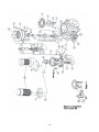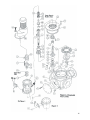
1
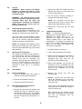
SERVICE MANUAL
MOYNO®
Pipeliner
TABLE OF CONTENTS
1-1. INTRODUCTION
1-2. GENERAL
1-3. NAMEPLATE DATA
1-4. Cutter Rotation
1-5. Model Number
1-6. Body Designation
1-7. Series Designation
1-8. Shearplate Hole Size
1-9. Drive Designation
1-10. Horsepower Designation
1-11. Style Designation
2-1. INSTALLATION
2-2. GENERAL
2-3. LIFTING PROCEDURE
2-4. SOLIDS REJECTION
2-5. PIPING AND VALVES
2-6. Piping
2-7. Valves
3-1. OPERATION
3-2. INITIAL CHECK
3-3. START-UP
3-4. SHUTDOWN
4-1. MAINTENANCE
4-2. GENERAL
4-3. SHEARPLATE-HEADSTOCK
INSPECTION
4-4. MECHANICAL SEAL
INSPECTION
Page
4-5. DISASSEMBLY
1
4-6. Disconnect Pipeliner
1
4-7. Motor/Housing Assembly
1
1
1
2
2
2
2
2
2
2
2
2
2
2
3
3
3
3
3
3
4
4
4
4
Removal
4-8. Cutterhead Disassembly
4-9. Drain Seal Chamber Oil
4-10. Seal Disassembly
4-11. Bearing Disassembly
4-12. CLEANING
4-13. INSPECTION
4-14. Bearings
4-15. Rotor Shaft and Headstock
Hub
4-16. Mechanical Seal
4-17. Headstock and Shearplate
4-18. Rings and Seals
4-19. REASSEMBLY
4-20. Lubrication During
Reassembly
4-21. Bearing Reassembly
4-22. Seal Reassembly
4-23. Spring Housing Reassembly
4-24. Fill Seal Chamber with Oil
4-25. Cutterhead Reassembly
4-26. Motor/Body Casting Assembly
4-27. Reconnect Pipeliner
4-28. STORAGE
4-29. SHEARPLATE VARIATIONS
4-30. STANDARD HARDWARE
4-31. PARTS LIST
Page
4
4
4
4
5
5
5
6
6
6
6
6
6
6
6
6
7
8
8
8
8
9
9
9
9
10
12
Section: Moyno Pipeliner
Page:
1
Date:
September 1998
Service Manual
Moyno® Pipeliner
Series 201, 301 and 401
1-1.
Introduction
1-2.
General
®
The Moyno Pipeliner is a rugged, industrialduty solids reduction unit that disintegrates
and grinds solids entrained in waste. The
Pipeliner prevents clogging of equipment and
permits the use of smaller diameter piping by
discharging more homogeneous liquids with
an effectively reduced particle size.
be used for reference when ordering spare
parts. To simplify this procedure, the model
number for your Pipeliner should be recorded
on the nameplate drawing on the front cover
of this manual. Please carefully file this
manual for future reference.
The cutting action of the Pipeliner consists of
a single shaft rotating a headstock,
containing tungsten carbide tipped cutting
edges running against a hardened tool steel
shearplate. The shearplate has a number of
holes in which to allow fluid to pass through.
Anything that goes through the Pipeliner must
go through these holes. As string and other
debris pass through the holes, the rotating
cutting edge of the headstock severs them.
Solids in the conveying liquid enter the unit’s
body chamber through a flanged inlet and
flow upward into the cutterhead assembly.
The macerated solids are then discharged
from the Pipeliner through a flanged outlet.
Tin cans, large pieces of metal and stones
will be screened from passing and can be
cleaned from the body casting.
1-4.
Cutter Rotation
As you stand facing the unit, the
shaft/headstock should be rotating from right
to left. You can check rotation by viewing the
shaft through the cover plate opening in the
bearing housing. Units supplied prior to May,
1995 do not have cover plates. Instead they
have pipe plug holes for viewing.
Note:
With its simple, rugged design, the Moyno
Pipeliner operates efficiently, requires less
maintenance than other solids reduction units
and can be serviced quickly using ordinary
tools. Its solids reduction capabilities offer
improved pumping to a variety of sewage,
waste and process industry applications.
1-3.
Do not attempt to verify rotation by
the fan on the motor.
The Moyno Pipeliner is not to be run in
reverse rotation.
1-5.
Nameplate Data
The Pipeliner nameplate, located on the body
casting, contains important operation and
service information. This information includes
the Pipeliner model and serial numbers (See
Figure 1-1).
The Pipeliner model and serial numbers must
1
Model Number
The Pipeliner model number consists of five
component parts: body designation, series
designation, shearplate hole size, drive
designation, horsepower rating and style
designation. A typical model number might be
P315G50A, as shown on the nameplate in
Figure 1-1.
1-6.
Body Designation
The body designation consists of one letter.
The letter “P” designates a Pipeliner body
type.
1-7.
Series Designation
The series designation consists of one
numeral that specifies grinder’s series. There
are three Pipeliner series designations:
2 - Series 201
3 - Series 301
4 - Series 401
1-8.
1-11.
Style Designation
If the model number of your Pipeliner is
followed by the letter “A”, you have received a
new style model. The new style consists of a
different bearing housing which includes a
D112 flange, for drive mounting, and coupling
inspection ports.
2-1.
Installation
2-2.
General
Moyno Pipeliners are lubricated and tested at
the factory before shipment and require
minimum pre-startup service.
Shearplate Hole Size
The shearplate hole size consists of a twodigit number that indicates the size of the
holes, expressed in millimeters. There are
five shearplate hole sizes:
06 - 6mm
08 - 8mm
10 - 10mm
15 - 15mm (nominal)
20 - 20mm (nominal)
Accessibility to the grinder and adequate
clearance should be a prime consideration in
any installation. Enough space should
surround the unit so the Pipeliner
maintenance can be performed easily.
The motor should be installed with flexible
conduit long enough to allow the motor to be
raised ten inches arid then lowered to the
floor. This will enable maintenance to be
performed without disconnecting wires.
The 15mm and 20mm (nominal) shearplates
have several diameter holes in them. The
multiple holes are necessary to ensure the
headstock remains dynamically balanced
through a full rotation. See chart below for
actual hole sizes.
The Moyno Pipeliner can only be mounted
vertically in the upright position. It is not
suited for submerged service.
2-3.
Model
P215
P315
P320
P415
P420
1-9.
Actual Hole Sizes
7,11,14mm
11, 15, 18mm
11, 17, 22mm
16, 18, 20, 24mm
12, 15, 16, 24, 28mm
1. Wrap a nylon lifting sling around the
Pipeliner bearing housing just below the
motor.
Drive Designation
The drive designation indicates the type of
drive system used to power the conditioning
unit. There are two drive designations:
2. If your Pipeliner is equipped with two side
blocks on the top of the bearing housing,
two special lifting brackets can be
attached for lifting see (Figure 2-1).
(Lifting brackets are optional; see Pages
12 and 13.)
D - Direct Drive
G - Gear Drive
1-10.
Horsepower Designation
The horsepower designation consists of a
two-or three-digit number that indicates the
horsepower rating of the motor used to drive
the conditioning unit. There are five
horsepower designations:
30 - 3
50 - 5
75 - 7 ½
100 - 10
150 - 15
Lifting Procedure
CAUTION:
Do not attempt to lift the
Pipeliner using the motor or gearmotor
lifting lugs. These lugs are for the
motor/gearmotor only. Lift the Pipeliner
by one of the following methods:
3. Remove the motor/gearmotor and attach
two lifting eye bolts (see Figure 2-2).
Lifting weights for each unit is listed below:
Model
201
301
401
Horsepower
Horsepower
Horsepower
Horsepower
Horsepower
2
LBS.
355
550
1300
2-7.
Valves
Valves that do not tend to clog should be
used to isolate the Pipeliner during service
procedures.
3-1.
Operation
3-2.
Initial Check
Before operating the Pipeliner check the
following items to ensure each piece of
equipment is installed correctly:
•
•
Figure 2-1. Typical lifting method using lifting
brackets.
•
3-3.
Figure 2-2. Typical lifting method using eye bolts.
2.4
Piping and Valves
2-6.
Piping
Suction piping should be as short as possible.
Normally, the suction line should be the same
size as the Pipeliner suction. Long sweep 90°
or 45° elbows should be used instead of
standard elbows.
Start-Up
CAUTION: Dry operation is harmful to the
Pipeliner! Never allow the Pipeliner to
operate without liquid for more than one
minute, as dry operation will cause
premature wear and possible damage to
the shearplate and headstock. The
shearplate and headstock are lubricated
by the liquid flowing through the unit.
1. Open the inlet and outlet valves to the
Pipeliner to start the flow of liquid to the
unit. Allow sufficient liquid to flow into the
unit to fill its body casting.
Solids Rejection
CAUTION: Objects that cannot be ground
could possibly damage the Pipeliner. Take
precautions to ensure that such items are
not fed into the unit.
2-5.
Electrical connections
Inlet and outlet valves (both valves should
be open)
Headstock rotation (the coupling should
rotate from right to left when viewed
through the coupling cover plate opening
in the bearing housing)
2. Start the Pipeliner.
3. Start the pump.
3
3-4.
Shutdown
It is necessary to have a sufficient velocity of
fluid in the system at all times in order to keep
particles in suspension and to ensure a free
flow in the discharge lines. If the system is to
be shut down for an extended period of time,
it is advisable to flush the piping with clean
water prior to shutdown.
4-1.
Maintenance
Note: In this section, the first reference to
each Pipeliner part will be followed by a
number in parentheses ( ). These numbers
identify the Pipeliner parts and hardware
items in the exploded views (Figures 4-1 and
4-2).
4-2.
General
WARNING: When servicing the Moyno
Pipeliner, be certain the power is off and
locked out. Serious injury can result from
accidental startup.
3. Remove the bolts, flat washers and lock
washers that attach the conversion ring
(2) to the body casting (1).
4. Lift the housing assembly vertically to
separate it from the body casting.
WARNING: The clean-out ports on either
side of the Pipeliner’s body casting are for
removing debris from the sump and
inspecting the shearplate and headstock
ONLY! They are not access ports for
Pipeliner maintenance.
4-3.
NOTE: The conversion ring has jack
screw holes which may be used to help
separate the assembly from the body.
5. Remove the O-ring (22) from the body
casting.
Shearplate-Headstock Inspection
Inspect the shearplate and headstock every
1,000 operating hours. If these parts are
damaged or excessively worn, replace them.
4-8.
The wear surface of the shearplate is raised
above the surface that fits in the conversion
ring. You can continue using the shearplate
as long as you have a raised surface.
NOTE: The shearplate and headstock can be
inspected by removing the cover plates (14)
and cover plate gaskets/O-ring (15) from the
body casting (1).
4-4.
1. Complete Sections 4-6 and 4-7.
Mechanical Seal Inspection
The Pipeliner’s mechanical seal operates in
an oil bath which cools and lubricates the
seal. The level and color of this oil should be
checked every time the shearplate and
headstock are inspected (see Section 4.3). If
the oil is heavily tainted or the level is
extremely low, the mechanical seal should be
inspected to make sure it is functioning
properly.
4-5.
Disassembly
4-6.
Disconnect Pipeliner
1. Flush the Pipeliner with clean water to
eliminate as much debris as possible.
2. Tip the housing assembly onto its side.
3. Remove the cap screws and lock washers
that hold the headstock (25) to the
headstock hub (26) and pull the
headstock off the headstock hub.
4. Remove the headstock cap (27) from the
headstock hub by unscrewing the cap
screws and removing the lock washers
that hold the headstock cap to the
headstock hub.
5. Remove the O-ring
headstock hub.
(32)
from
the
6. 201/301 - Remove the set screws that
attach the shearplate to the conversion
ring and pull the shearplate from the
conversion ring.
2. Open the circuit breaker and tag it.
3. Close the inlet and outlet valves.
4-7.
Cutterhead Disassembly
NOTE:
To replace the shearplate and
headstock only, complete Steps 1, 2, 3 and 6.
Reassemble in reverse order (6, 3, 2, 1).
Whenever the cutters are replaced, you
should complete Step 4 and inspect for
contamination. If pumpage has entered the
spline area, complete disassembly through
Step 10. If not, replace the headstock cap
and continue reassembly.
Motor/Housing Assembly Removal
1. Complete Section 4-6.
If worn, remove the shearplate key (34) by
unscrewing the set screw that attaches it
to the conversion ring.
2. Remove the bolts and lock washers that
attached the motor or gearmotor (36) to
the bearing housing (3) or motor adapter
(37). Lift the drive vertically, separating it
from the bearing housing, and place it on
the floor.
401 - Remove the four shoulder screws
attaching the shearplate to the conversion
ring. Pull the shearplate from the
conversion ring.
4
housing liner away from the conversion
ring. Remove the O-ring (20).
7. Remove the headstock hub by unscrewing
the cap screws and lock washers that hold
the headstock hub to the spring housing
5. Remove the stationary portion of the
mechanical seal (12) from the seal
housing liner.
(28).
8. Slide the headstock hub off the spline.
Remove the O-ring (31) from the spring
housing.
4-11.
9. 201/301 - Remove the set screws from
one of the two holes in the special nut (33)
and unthread the special nut from the rotor
shaft (4).
2. Remove the spacer (10) from the rotor
shaft then remove the O-ring (18) from the
spacer.
401 - Remove the cap screw that holds
the locking tab (34) to the special nut (33).
Remove the locking tab, then unthread the
special nut from the rotor shaft (4).
3. Remove the coupling half (23) from the
rotor shaft by first removing the coupling
cover plate (40) from the bearing housing.
Through the opening, loosen the
coupling’s set screws (J) and pull the
coupling half off the rotor shaft. Remove
the shaft key and store it with the coupling
half.
NOTE: It will be necessary to hold the
rotor shaft with the headstock hub while
unthreading the special nut. Partially
thread two cap screws in the headstock
hub to function as fulcrum points for a
lever.
4. Remove the bearing and seal cap (8) by
first unscrewing the cap screws, flat
washers and lock washers that attach the
cap to the bearing housing. Rethread two
cap screws into jacking holes in the cap
and tighten evenly until the cap can be
removed. Remove the O-ring (41) from the
bearing housing bore.
10. Remove the springs (29) from the spring
housing and pull the spring housing from
the rotor shaft (4).
4-9.
Drain Seal Chamber Oil
1 Complete Sections 4-6 and 4-7.
2. 201/301 - remove the pipe plug (B) from
the bearing housing (3).
5. Place the bearing and seal cap in a vise.
Using a punch and hammer, gently tap on
the inside surface of the rollers until the
bearing (5) comes from the cap. Remove
the lip seal (17) from the cap.
401 - remove the oil level stick (42) from
the bearing housing (3).
3. Tip the housing assembly on its side and
allow the oil to drain through the drain
hole.
4-10.
Bearing Disassembly (201/301)
1. Remove the bolts, flat washers and lock
washers that attach the conversion ring (2)
to the bearing housing (3) and remove the
conversion ring. Remove the O-ring (21).
6. Gently tap the rotor shaft (4) through the
bearing housing from the coupling end of
the housing and out through the end of the
housing that attaches to the conversion
ring.
Seal Disassembly
1. Complete Sections 4-7 through 4-9.
2. Pull the rotating portion of the mechanical
seal, (12) complete with seal sleeve (11),
off the rotor shaft. Loosen the set screws
that hold the rotary portion of the seal on
the sleeve and slide it off the sleeve.
7. Remove the lip seal (16) from the bearing
housing.
8. Remove the bearing spacer (7). Remove
the snap ring (9) from the rotor shaft.
Press the ball bearing (6) from the rotor
shaft. Place the rotor shaft in a vise. Using
a hammer and punch, tap the inner race of
the roller bearing until it comes off the
rotor shaft.
3. Remove the O-rings (30 and 19) from the
seal sleeve (11).
4. Remove the cap screws and lock washers
that attach the seal housing liner (13) to
the conversion ring (2) and pull the seal
5
4-11.
Bearing Disassembly (401)
1. Remove the coupling half (23) from the
rotor shaft by first removing the coupling
cover plate (46) from the bearing housing.
Through the opening, loosen the
coupling’s set screws (J) and pull the
coupling half off the rotor shaft. Remove
the shaft key (I) and store it with the
coupling half.
2.
Pay particular attention to the splines of the
rotor shaft. Replace as necessary.
Remove the bearing cap (8) by first
unscrewing the cap screws, flat washers
and lock washers that attach the cap to
the bearing housing. Rethread two cap
screws into jacking holes in the cap and
tighten evenly until the cap and gasket
(45) can be removed.
3.
Place the bearing cap in a vise and
remove the lip seal (17).
4.
Remove the bearing and seal cap (9) by
first removing the cap screws and
washers. Place the bearing and seal cap
in a vise and remove the lip seal (10).
5.
Place the bearing housing assembly into a
vise. From the coupling end of the shaft,
press the rotor shaft/bearing assembly
from the bearing housing.
6.
Push the outer race of the roller bearing
(6) from the bearing housing.
4-16.
Mechanical Seal
Inspect the contact faces on the mechanical
seal (12) for damage. Replace if there is any
doubt concerning serviceability.
4-17.
Headstock and Shearplate
Examine the cutting edge on the headstock
(25) and the shearplate (24) for damage and
excessive wear. Replace as necessary.
4-18.
O-Rings and Seals
It is good practice to always replace all O-rings
and lip seals whenever the Pipeliner is
disassembled.
4-19.
Reassembly
The Moyno Pipeliner is reassembled in
reverse order of disassembly.
1.
4-20.
7. Unthread the bearing lock nut (16) by first
bending back the tab on the lock washer
(18).
Lubrication During Reassembly
1. Bearings and Seal (201/301). Pack the
roller bearing (5) prior to reassembly into
the bearing housing (3). The ball bearing
(6) is pre-lubricated and sealed and does
not
need
additional
lubrication.
Mechanical seal lubricating oil should be
poured through the oil level stick hole
after the Moyno Pipeliner is completely
reassembled.
Bearings and Seal (401). Pack both the
roller and ball bearings with grease prior
to reassembling them in the bearing
housing. The mechanical seal lubricating
oil should be poured through the hole
provided for the oil level stick.
8.
4-12.
Press both bearings (5 and 6) and bearing
spacers (7 and 48) from the rotor shaft
(4).
9. Press the lip seal (41) from the outer
bearing spacer (48).
Cleaning
Clean all parts in a suitable cleaning solvent,
being careful to observe all safety precautions
regarding the use of the solvent.
4-13.
Inspection
4-14.
Bearings
After cleaning, rotate the bearings (5 and 6)
slowly, feeling for smoothness and even
action. Check for cracks, galling, pitting, burrs,
overheating, etc. Replace bearings if there is
any doubt concerning complete serviceability.
4-15.
During
the
reassembly
process,
cleanliness is important. To avoid
premature failure, all components must be
handled with care and kept clean.
Note: The minimum oil level
indicated on the oil level stick.
2.
Rotor Shaft and Headstock Hub
Inspect the rotor shaft (4) and headstock hub
(26) for scoring, burrs, cracks, excessive
wear, etc.
6
is
Approved Lubricants:
CAUTION: Do not mix different brands
of lubricants.
Area to
Lubricate
Approved Lubricant
or Equivalent
Bearings
Dubois ACG2
(Dubois Chemical Co.)
Mechanical
Seal
Mobil D.T.E. 24
(Mobil Chemical Co.)
4-21.
Bearing Reassembly (201/301)
1. Press new lip seals (16 and 17) in the
bearing housing (3) and bearing and seal
cap (8). The lips on the seals should be
facing outward, away from the bearings.
2.
Press new lip seals (10 and 17) in the
bearing and seal cap (9) and the bearing
cap (8). The lips at both seals should be
facing outward, away from the bearings.
3.
Press the ball bearing (5) against the
shoulder on the rotor shaft. Install the
inner bearing spacer.
4.
Pack a liberal amount of grease between
the ball of the bearing. Install the outer
bearing spacer.
5.
Press the inner race/roller assembly of the
roller bearing (5) against the inner bearing
spacer.
6.
Place the lock washer (18) on top of the
roller bearing then thread the bearing lock
nut (16) onto the rotor shaft and tighten it.
Bend one of the lock washer tabs up into
one of the slots in the lock nut.
7. Pack the roller bearing and bearing spacer
with approximately one cup of grease.
7.
8. Install the bearing and seal cap. Make
sure the four holes in the cap line up with
the holes in the bearing housing and that
the cap slides evenly into place.
Pack a liberal amount of grease between
the
rollers.
You
should
apply
approximately one cup of grease between
the two bearings.
8.
Press the rotor shaft/bearing assembly
into the bearing housing until the outer
bearing spacer rests against the shoulder
in the housing.
9.
Push the outer race of the roller bearing
down into position around the roller
assembly.
2. Press the ball bearing (6) against the
shoulder on the rotor shaft (4) and attach
the snap ring (9) to fix the bearing’s
location on the rotor shaft.
3. Press the inner ring of the roller bearing
(5) against its shoulder on the rotor shaft.
4. Gently tap or press the rotor shaft into the
bearing housing through the end of the
housing that attaches to the conversion
ring (2). Install the bearing spacer (7) on
the rotor shaft.
5. Press the outer race of the roller bearing
into the bearing and seal cap.
6. Push O-ring (41) into bearing housing bore
until it bottoms out against the bearing.
CAUTION: It is important that the bearing
and seal cap be installed evenly in the
bearing housing to prevent scoring on the
ball bearing’s inner ring surface.
9. Attach the bearing and seal cap to the
bearing housing using four cap screws,
flat washers and lock washers. Tighten
the screws evenly.
10.
10. Install a new gasket (45) then the bearing
cap (8) and evenly tighten the cap screws
and washers.
Verify that the rotor shaft rotates freely in
the bearing housing and there is no shaft
end movement.
11. Install the bearing and seal cap, then
evenly tighten the cap screws and
washers.
11. Place O-ring (21) in the groove and attach
the conversion ring to the bearing housing
using eight hex head bolts, flat washers
and lock washers.
4-21.
12. Verify that the rotor shaft rotates freely in
the bearing housing and there is no shaft
end movement.
Bearing Reassembly (401)
1.
Press a new lip seal (41) in the outer
bearing spacer.
13. Place the O-ring (21) in its groove and
attach the conversion ring to the bearing
housing using eight bolts, flat washers
and lock washers.
7
4-22.
Seal Reassembly
1. Place a new O-ring (20) in the seal
housing liner and attach it to the
conversion ring with four cap screws.
Tighten all screws evenly.
2.
housing (28) using cap screws and lock
washers.
4-24.
201, 301 - Install new O-rings (18 and 19)
in the spacer (10) and slide it onto the
rotor shaft.
Fill Seal Chamber With Oil
1. 201/301 - Install the pipe plug (B) in the
bearing housing (3).
Fill the seal chamber with oil to the level
indicated on the oil level stick (35).
401 - Install a new O-ring (17) into the seal
sleeve
3.
4.
5.
401 - Fill the seal chamber with oil to the
level indicated on the oil level stick (42).
Install a new O-ring in the stationary
portion of the mechanical seal and gently
push it into the seal housing liner.
2.
Place the rotating portion of the seal on
the seal sleeve against the shoulder.
Tighten the set screws. Gently slide this
assembly onto the rotor shaft until the seal
faces contact.
4-25.
Place O-ring (30) in groove in the seal
sleeve.
Cutterhead Reassembly
1. 201/301 - Attach the shearplate key (34)
to the conversion ring using a set screw.
Place the shearplate (24) into position on
the conversion ring (2) so the slot aligns
with the shearplate key.
NOTE: Mechanical seal compression is
set when the special nut is tightened on
the rotor shaft.
4-23.
Attach the shearplate to the conversion
ring by tightening the four set screws.
Spring Housing Reassembly
1. Install the spring housing (28) on the rotor
shaft. Grease the springs (29) and install
them in the spring housing.
2.
Thread the special nut (33) onto the rotor
shaft.
3.
201/301 - Install the set screw in the
special nut through one of the tapped
holes so that the set screw rests in one of
the valleys of the spline. Use a small
amount of Loctite on the set screw
threads.
401 - Attach the shearplate to the
conversion ring by tightening the four
shoulder screws and lock washers.
401 - Place the locking tab (34) in the
valley at the spline and against the special
nut, then fasten it in place with a cap
screw.
NOTE: It will be necessary to hold the
rotor shaft with the headstock hub while
tightening the special nut. Use the lever
technique described in Section 4-8.9.
4.
Place O-ring (31) in groove in the spring
housing.
5.
Grease the splines of the rotor shaft (4)
and place the headstock hub (26) on the
shaft.
6.
Attach the headstock hub to the spring
Check for oil leaks while the rotor shaft is
stationary. Hand rotate the shaft, checking
for oil leaks and for free shaft movement.
There should be no leakage.
4-26.
8
2.
Attach the headstock (25) to the
headstock hub using cap screws and lock
washers. Use a small amount of Loctite
on the cap screw threads.
3.
Check for free rotation of the headstock.
4.
Place a new O-ring (32) into the groove on
the headstock hub.
5.
Attach the headstock cap (27) to the
headstock hub using socket cap screws
and lock washers.
Motor/Body Casting Assembly
1. Clean the inside diameters and top face of
the body casting (1).
2.
Install a new O-ring (22) in the body
casting.
3.
Install the bearing housing assembly in
the body casting, making sure that the
dowel pin hole in the conversion ring (2)
aligns with the dowel pin in the body
casting.
4-27.
4-28.
4.
Secure in position using bolts, flat
washers and lock washers.
5.
Reinstall and connect the Pipeliner
motor using bolts and lock washers.
to ensure the headstock remains
dynamically balanced through a full
rotation. See chart below for actual
hole sizes.
Reconnect Pipeliner
1. Connect the power source.
2.
Open the inlet and outlet valves to the
Pipeliner to start the flow of conveying
liquid to the unit. Allow sufficient liquid
to flow into the unit to fill its body
casting.
3.
Start the Pipeliner.
4.
Start the pump.
Model
P215
P315
P320
P415
P420
Storage
Storage of one year or less will not damage
the Pipeliner. However, to ensure the best
possible protection, the following is advised:
1.
Store the Pipeliner inside (33°F to
155°F) in a vertical position and cover
to protect it from dust. Do not allow
moisture to collect around the Pipeliner.
2.
If possible, store the Moyno Pipeliner in
its original shipping container.
3.
Coat the surface of the shearplate and
headstock with a rust inhibitor.
4.
Extended storage may cause grease to
separate. A small amount of oil may
leak from the greased areas and from
around the mechanical seal. The
grease will homogenize to its original
consistency when the unit is started, but
the
lubricant
levels
should
be
maintained.
4-29.
Shearplate Variations
Shearplates identified on the parts
listing have a standard hole size of 15
mm. Other sizes may be ordered by
selecting the standard shearplate part
number and changing the last two digits
as follows:
06 - 6mm
08 - 8mm
10 - 10mm
15 - 15mm (nominal)
20 - 20mm (nominal)
The 15mm and 20mm (nominal)
shearplates have several diameter
holes in them. The multiple holes are
necessary
9
Actual Hole Sizes
7,11,14mm
11,15,18mm
11,17, 22mm
16, 18, 20, 24mm
12, 15, 16, 24, 28mm
4-30. Standard Hardware - 201/301
Ref. No.
A
B
C
D
E
F
G
H
I
J
K
L
M
N
O
(201 Only)
O
(301 Only)
P
(201 Only)
P
(301 Only)
Q
R
Description
.50-13 UNC X 2" Hex Head Cap Screw
.50 Lock Washer
.50-13 UNC Hex Nut
.125 BSP Plug
M8 X 30 Long Hex Head Cap Screw
M8 Flat Washer
M8 Lock Washer
M6 X 25 Long Hex Head Cap Screw
M6 Flat Washer
M6 Lock Washer
M5 X l2 Socket Head Screw
M5 Lock Washer
M8 X 40 Long Hex Head Cap Screw
M8 Flat Washer
MB Lock Washer
MB X 30 Long Hex Head Cap Screw
M8 Flat Washer
M8 Lock Washer
M10 X 40 Long Hex Head Cap Screw
M10 Flat Washer
M10 Lock Washer
Shaft Key 10 X 8 X 40 Long
M8 X 16 Long Socket Set Screw - Cup Pt.
M5 X 12 Socket Head Screw
M5 Lock Washer
M8 X 25 Socket Head Screw
M8 Lock Washer
M8 X 35 Socket Head Screw
M8 Lock Washer
M6 X 10 Long Socket Set Screw - Cone Pt.
M6 X 6 Long Socket Set Screw - Cone Pt.
M6 X 10 Long Socket Set Screw - Cone Pt.
M5 X 12 Socket Head Screw
Part Number
6191550321
6230010431
6140050051
4220219001
6191724300
6230722070
6230714080
6191714250
6230722060
6230704060
6191804120
6230704050
6191724400
4220213008
6230714080
6191724300
6230722070
6230714080
6191734400
6230722080
6230714100
6111030400
4220355000
6191804120
6230704050
6191824250
6230714080
6191824350
6230714080
6061232100
6061232060
6061232100
6191804120
Qty.
4
4
4
1
8
8
8
4
4
4
4
4
8
8
8
16
16
16
4
4
4
1
4
3
3
3
3
3
3
1
4
4
1
M6 X 12 Socket Head Screw
6191814120
1
M12 X 30 Hex Head Bolt
.50-13 UNC X .75 Socket Head Cap Screws
6191744300
6191480123
4
4
10
Standard Hardware - 401
Ref. No.
A
C
D
E
F
G
H
I
J
K
L
M
N
O
P
Q
R
S
Description
.50-13 UNC X 2” Hex Head Cap Screw
.50 Lock Washer
M8 X 30 Long Hex Head Cap Screw
M8 Flat Washer
M8 Lock Washer
M6 X 20 Long Socket Head Screw
M6 Lock Washer
M12 X 30 Hex Head Bolt
M12 X 50 Long Hex Head Cap Screw
M12 Flat Washer
M12 Lock Washer
M8 X 40 Long Hex Head Cap Screw
M8 Flat Washer
M8 Lock Washer
M8 X 25 Long Socket Head Screw
M8 Lock Washer
Shaft Key 10 X 8 X 45 Long
M8 X 16 Long Socket Set Screw - Cup Pt.
M5 X 16 Long Socket Head Screw
M5 Lock Washer
M8 X 20 Long Socket Head Screw
M8 Lock Washer
M10 X 35 Long Socket Head Screw
M10 Lock Washer
M5 X 12 Long Socket Head Screw
M5 Lock Washer
.75-10 UNC X 2.25 Hex Hd. Cap Screw
.75
Flat Washer
.75
Lock Washer
M6 X 12 Lg. CSK. Socket Set Screw
.75 BSP Hex Head Pipe Plug
M8 X 16 Socket Shoulder Screw
1” BSP Pipe Plug
11
Part Number
6191550321
6230010431
6191724300
6230722070
6230714080
6191814200
6230704060
6191744300
6191740501
6230720091
6230700121
6191724400
6230722070
6230714080
6191824250
6230714080
4220292000
4220355000
6191804160
6230704050
6191824200
6230714080
6191834350
6230714100
6191804120
6230704050
6191580361
6230030071
6230010431
4220303000
4220499075
4220254000
4220499100
Qty.
4
4
8
8
8
4
4
4
6
6
6
8
8
8
4
4
1
4
4
4
6
6
6
6
3
3
16
16
16
1
1
4
2
4-31.
Ref. No.
1
2
3
4
5
6
7
8
9
10
11
12
13
14
15
16
17
18
19
20
21
22
23
24
25
26
27
28
29
30
31
32
33
34
35
36
37
38
39
40
41
Parts List - 201/301
Description
201
301
Body Casting
(1) MP2021
MP3021
Conversion Ring
(1) MP2031
MP3031
Bearing Housing
(1)MP2051
MP2051
Rotor Shaft
(1) MP2261
MP2261
Roller Bearing
(1) MP2291
MP2291
BalI Bearing
(1) MP2311
MP2311
Bearing Kit (See Note A) (1) KMP291
KMP291
Bearing Spacer
(1) MP2331
MP2331
Bearing and Seal Cap
(1) MP2341
MP2341
Snap Ring
(1) MP2085
MP2085
Spacer
(1) MP2541
MP2541
Seal Sleeve
(1) MP2531
MP2531
Mechanical Seal
(1) MP248Q MP248Q
Seal Housing Liner
(1) MP2432
MP2432
Cover Plate
(2) MP2171
MP2171
Cover Plate Gasket
(2) MP279F MP279F
Lip Seal
(1) MP2621
MP2621
Lip Seal
(1) MP2611
MP2611
O-Ring
(1) MP2111
MP2111
O-Ring Kit (See Note B)
(1) KMP21F KMP31F
O-Ring
(1) MP2112
MP2112
O-Ring
(1) MP2113
MP2113
O-Ring
(1) MP2114
MP2114
O-Ring
(1) MP2115
MP3115
Coupling
(1)
See Note C
Shearplate (15mm nominal)(1) MP2615
MP3615
Headstock
(1) MP2222
MP3221
Headstock Hub
(1) MP2345
MP2345
Headstock Cap
(1) MP4355
MP4355
Spring Housing
(1) MP2365
MP2365
Spring, Stainless Steel
(*) MP2375
MP2375
O-Ring
(1) MP2116
MP2116
O-Ring
(1) MP2117
MP2117
O-Ring
(1) MP2118
MP2118
Special Nut
(1) MP2435
MP2435
Shearplate Key
(1) MP2445
MP3445
Oil Level Stick
(1) MP2001
MP2001
Gearmotor
(1)
**
**
Adapter Plate
(1)
See Note D
Lifting Bracket
(2) MP4441
MP4441
Coupling Cover Plate
(2) MP4437
MP4437
Coupling Plate Gasket
(2) MP4438
MP4438
O-Ring
(1) MP2119
MP2119
12
Note A: Bearing kit includes items 5, 6,
16 and 17.
Note B: O-ring kit includes items 18, 19,
20, 21, 22, 30, 31, 32 and 41.
*Three springs are required for the
201 model; four are required for the 301.
**Gearmotors are standard vertical
mount, D-flange design. See nameplate
for details.
Note C:
Eurodrive
CoupIing
1
Model
P/N
RF60...
MP2060
RF77...
MP3075G
RF70...
MP3065
RF80...
MP4011G
RF67...
MP2065
RF87...
MP4011G
(1)
Look on the gearmotor name tag for
model number.
Note D:
Catalog #
MP2815
MP3815
Description
Adapts 213 - 215TC
motor to the D112M
flange of Pipeliner.
Adapts 254 - 256TC
motor to the D112M
flange of Pipeliner.
Parts List - 401
No.
Description
1
BodyCasting
(1)
2
Conversion ring
(1)
3
Bearing Housing
(1)
4
Rotor Shaft
(1)
5
Ball Bearing
(1)
6
Roller Bearing
(1)
Bearing Kit (See Note A)
(1)
7
Inner Bearing Spacer
(1)
8
Bearing Cap
(1)
9
Bearing & Seal Cap
(1)
10
Lip Seal
(1)
11
Seal Sleeve
(1)
12
Mechanical Seal
(1)
13
Seal Housing Liner
(1)
14
Blanking Flange
(2)
15
O-Ring
(2)
16
Bearing Lock Nut
(1)
17
Lip Seal
(1)
18
Bearing Lock Washer
(1)
O-Ring Kit (See Note B)
(1)
19
O-Ring
(1)
20
O-Ring
(1)
21
O-Ring
(1)
22
O-Ring
(1)
23
Coupling
(1)
24
Shearplate (15mm nominal) (1)
25
Headstock
(1)
26
Headstock Hub
(1)
27
Headstock Cap
(1)
28
Spring Housing
(1)
29
Spring, Stainless Steel
(8)
30
O-Ring
(1)
31
O-Ring
(1)
32
O-Ring
(1)
33
Special Nut
(1)
34
Lock Tab
(1)
36
Gearmotor
(1)
38
Lifting Bracket
(2)
40
Spring Pin
(1)
41
Lip Seal
(1)
42
Oil Level Stick
(1)
46
Coupling Cover Plate
(2)
Coupling Cover Plate Gasket (2)
47
48
Outer Bearing Spacer
(1)
401
MP4021
MP4031
MP4051
MP4261
MP4291
MP4311
KMP492
MP4331
MP4341
MP4129
MP479Q
MP4541
MP488Q
MP4432
MP4128
MP4531
MP4621
MP4611
MP4130
KMP491
MP4112
MP4113
MP4114
MP4115
See Note C
MP4615
MP4221
MP4345
MP4355
MP4365
MP2375
MP4116
MP4117
MP4118
MP4119
MP4120
*
MP4441
MP4126
MP4440
MP2001
MP4437
MP4438
MP4439
13
Note A:
Bearing kit includes items 5, 6, 10, 16, 17
and18.
Note B:
O-ring kit includes items 15 (two O-rings),
19, 20, 21, 22, 30, 31 and 32.
Note: All items designated with a letter
are standard hardware items.
Moyno does not supply these items.
The items can be obtained locally.
*Gearmotors are standard vertical mount,
D-flange design. See nameplate for
details.
14
15
®
©
Moyno is a registered trademark of Moyno, Inc.
1998 Moyno, Inc.
Moyno, Inc. is a Unit of Robbins & Myers, Inc.