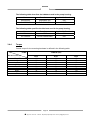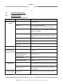
1
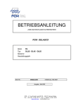
INSTRUCTION
MANUAL
TO BE KEPT FOR FUTURE REFERENCE
PCM - DELASCO
Series
DL
Type
DL35 - DL45 - DL55
Serial No.
Year of manufacture
Document No.:
NIDEDL505A
Date approved : January 2000
Date issued : January 2000
PCM POMPES-17 RUE ERNEST LAVAL-BP 35-92173 VANVES CEDEX France TEL: (33) 01 41 08 15 15
FAX: (33) 01 41 08 15 00 - TELEX: 634129 – Internet : http:/www.pcmpompes.com Email : [email protected]
DECLARATION OF INCORPORATION
We hereby state that the sub-assembly referred to in the technical specifications sheet
cannot be put into service until the machine in which it is to be incorporated is
declared compliant with the provisions of Council Directive 89/392/CEE of the Machine
Directive 91/368/CEE modified 93/44/CEE and 93/68/CEE, and with the national
legislation expressing it.
The sub-assembly is compliant with the EN 292 harmonised norms.
Vanves, 23/04/1996
For: Company name and position
Innovation Manager
B. LAFONT
!: (33) 01 41 08 15 15 - Internet : http:/www.pcmpompes.com
Email : [email protected]
Thank you for selecting a pump from the PCM range
6 PRODUCT LINES
PCM MOINEAU
The widest range of industrial progressive cavity pumps.
PCM PRECI-POMPE
Electro-mechanical diaphragm and plunger dosing pumps.
PCM MOINEAU OILFIELD
Progressive cavity pumps for oil extraction.
PCM DELASCO
The most complete range of peristaltic pumps.
PCM DOSYS
Precision pumpheads and continuous mixers.
PCM EQUIPMENT
Lobe pumps and rotary piston pumps,
Pipeliner-grinders.
PCM markets its products throughout the world via a distribution network
consisting mainly of subsidiaries and agents. All are approved by PCM, and
are able to provide Service and Assistance.
!: (33) 01 41 08 15 15 – Internet : http:/www.pcmpompes.com
Email : [email protected]
CONTENTS
0. INTRODUCTION
0.1
General
1
0.2
Limits of Guarantee
2
1. SPECIFICATIONS AND INSTALLATION
1.1
Operating Principle
3
1.2
1.2.1
1.2.2
Specifications
Build Specifications
Operating Specifications
4
4
9
1.3
1.3.1
1.3.2
1.3.3
Equipment Installation
Installation Precautions
Pipework Connection
Motor Connection
10
10
13
13
2. OPERATION
2.1
2.1.1
2.1.2
Commissioning
Before Start-Up
Start-Up
15
15
15
2.2
2.2.1
2.2.2
2.2.3
Normal Operating Procedure
Start-Up Procedure
General Operating Precautions
Shutdown Procedure
15
15
16
16
2.3
Operating Procedure in the Event of an Incident
16
2.4
Automatic Control
16
!: (33) 01 41 08 15 15 – Internet : http:/www.pcmpompes.com
Email : [email protected]
3. MAINTENANCE
3.1
List of Spare Parts
17
3.2
Handling Equipment and Procedure
20
3.3
Storage Conditions
20
3.4
3.4.1
3.4.2
3.4.3
3.4.4
Preventive Maintenance
Periodic Inspection
Cleaning
Lubrication
Torque
20
21
21
21
22
3.5
3.5.1
3.5.2
3.5.3
Corrective Maintenance
Troubleshooting
Disassembly
Reassembly
23
23
24
26
3.6
Equipment Storage when not in Use
29
3.7
Accessories
29
4. APPENDICES
PCM standard painting procedure
Technical Description
Accessories (optional)
Automatic System (optional)
!: (33) 01 41 08 15 15 – Internet : http:/www.pcmpompes.com
Email : [email protected]
0. INTRODUCTION
0.1
General
The pump you have just acquired was manufactured and inspected with the utmost care.
The purpose of this instruction manual is to help you maintain the correct operating
conditions for your pump.
Identification Plate
This plate, located on the back of the pump stator, gives the following information:
a)
Serial Number
b)
Pump part number, which breaks down according to the following examples:
- Most common Part Number
DL55PA4P
DL55 specifies pump model and type
P specifies lining type
A specifies drive assembly type
4P specifies outlet type
Note:
The coding of equipment delivered is clearly set out in this form in the
technical description in Section 4: Appendices
c)
Maximum pump capacity at maximum pressure
d)
Maximum pressure allowed by the pump
e)
Customer reference
This information is essential for all spare part orders (contact our Customer Service
Department).
Pump characteristics (capacity, pressure, speed of rotation,
construction, etc.) must not be changed without the written agreement
of our Customer Service Department.
Page 1
!: (33) 01 41 08 15 15 – Internet : http:/www.pcmpompes.com
Email : [email protected]
0.2
Limits of Guarantee
Before performing any maintenance operations on the pump,
check that all necessary precautions have been taken: upstream
and downstream valves closed, pipes cleaned and purged,
electrical power supply disconnected and all usual measures
concerning the safety of personnel to be taken according to the
texts in force.
On receiving the pump, examine it immediately to check that no signs of damage are
apparent. If the pump is visibly damaged, indicate clearly on the carrier's documents that
the merchandise was received damaged, with a brief description of the type of damage
observed. Send a registered letter with acknowledgement of receipt to the carrier within
48 hours, and a copy to our Customer Service Department if you have accepted the
damaged equipment.
Storage and handling conditions are explained in Section 3, paragraphs 3.2 and 3.3.
To avoid all risk of damage or accidents (in particular when the products being conveyed
are hazardous), it is essential that you do not use the equipment for an application other
than the one provided for in our technical description (see Section 4 - Appendices).
To maintain the original properties of the pump, it is essential to use parts manufactured
by PCM POMPES.
Page 2
!: (33) 01 41 08 15 15 – Internet : http:/www.pcmpompes.com
Email : [email protected]
1. SPECIFICATIONS AND INSTALLATION
1.1
Operating Principle
ROLLER
PUMP
HOUSING
HOSE
FLANGE
INSERT
COVER
DEFLECTOR
ROTOR
Page 3
!: (33) 01 41 08 15 15 – Internet : http:/www.pcmpompes.com
Email : [email protected]
The principle of peristaltic pumping is based on the ability of a hose made of a flexible
material (elastomer type) to deform and then return to its initial shape.
A drive causes the rotor equipped with a roller to rotate. The hose is compressed by the
roller, and closes occlusively. Behind the roller, the return of the hose to its initial shape
creates a vacuum, which exerts suction on the product. The volume of product between
two rollers is transferred inside the hose from the suction part of the pump to the
discharge part. Under the pressure of the second roller, the product is discharged in the
pipework.
The capacity obtained varies according to hose diameter, and the rotational speed of the
rotor.
Direction of Rotation
The pump's symmetric construction makes it fully reversible by simply changing the
direction of rotation. Maximum pump performance characteristics and specifications are
obtained in both directions.
1.2
Specifications
1.2.1
Build Specifications
Defined in the table below:
Hose
NR or EPDM or NBR
Pump housing
Cast iron FGL 250
Pump cover
Cast iron FGL 250
Rotor
Cast iron FGL 250
Roller
Cast iron FGL 250 + Composite
Polypropylene
or stainless steel 304L (Z2CN18-10)
Insert
Food-grade construction: Stainless
steel 316L (Z2CND17-12)
Flange
Steel A33
Deflector
Steel E24
NOTE: Unless otherwise stated our pumps are protected with a protective paint; the
procedure and application instructions for which are defined in the PCM
standard painting procedure specification sheet 1 (See Section 4,
Appendices). For other types of coating or specific requirements, the
relevant procedure should be requested when ordering the equipment or
from our Customer Service Department.
Page 4
!: (33) 01 41 08 15 15 – Internet : http:/www.pcmpompes.com
Email : [email protected]
TYPE OF FITTING
According to French standard NF E 29-203 Threaded tip according to standard SMS1145
PN20 DN32
DN 38
PN20 DN40
DN 51
PN20 DN50
DN 63.5
PUMP
DL35
DL45
DL55
General Dimensions
Bearing pump (bare shaft)
A
C
B
H
J
L
K
S
G
F
R
E
D
M
4 x Ø 18
20
360
360
H2
960
1000
PUMP
DL35
DL45
DL55
A
214
222
253
B
312
310
491
C
117
127
152
D
70
70
100
E
40f7
40f7
50f7
F
732
810
965
770
G
490
490
565
H
H
FLANGE
SMS
303
387
444
333
421
487
H2
J
K
M
R
S
480
88.9
98.4
120.6
4xM14
4xM14
4xM16
20
20
45
352
477
600
314
252
265
Mass
(Kg)
VACUUM NOT VALID WHEN PUMP DL55 HAS SMS TYPE FOOD INSERT
Page 5
!: (33) 01 41 08 15 15 – Internet : http:/www.pcmpompes.com
Email : [email protected]
190
287
515
Monobloc Pump DL35
GEAR MOTOR
VARIABLE SPEED GEAR
B3
B2
Ø H1
B1
490
Z
Z1
Ø H1
20
265
GEAR MOTOR
Motor
power
in kW
0.37
Ø H1
145
VARIABLE SPEED GEAR
0.55/0.75 1.1/1.5 2.2/3
145
197
197
4
Motor
power
in kW
2,2
3
4
221
Ø H1
197
197
221
B2
701
701
B3
B1
Mass
en Kg
505
204
555
208
573
214
623
221
659
231
863
Z1
245
245
305
Z
831
831
919
Mass
en Kg
263
268
303
Page 6
!: (33) 01 41 08 15 15 – Internet : http:/www.pcmpompes.com
Email : [email protected]
Monobloc Pump DL45
GEAR MOTOR
VARIABLE SPEED GEAR
B3
B2
Ø H1
B1
490
Z
Z1
Ø H1
20
265
GEAR MOTOR
Motor
power
in kW
ØH1
VARIABLE SPEED GAER
0.75
1.1/1.5
2.2/3
4
5.5
145
197
197
221
221
Motor
power
in kW
ØH1
B2
2.2
4
5.5
197
221
221
699
B3
B1
Mass
en Kg
553
305
571
311
621
318
657
328
702
333
861
906
Z1
245
305
305
Z
831
919
919
Mass
en Kg
360
400
410
Monobloc Pump DL55
Page 7
!: (33) 01 41 08 15 15 – Internet : http:/www.pcmpompes.com
Email : [email protected]
GEAR MOTOR
VARIABLE SPEED GEAR
B3
B1
Z1
Ø H1
565
Z
Ø H1
20
245
GEAR MOTOR
VARIABLE SPEED GEAR
Motor
power
in kW
0,75
1,1/1,5
2,2/3
4
5,5
7,5
Motor
power
in kW
4
7,5
9,2
Ø H1
145
197
197
221
221
275
Ø H1
221
275
275
B3
928
1018
1078
789
Z1
305
380
380
Z
997
1105
1105
560
Mass
en Kg
605
680
690
B1
Mass
en Kg
620
507
639
515
689
523
724
532
769
538
Page 8
!: (33) 01 41 08 15 15 – Internet : http:/www.pcmpompes.com
Email : [email protected]
1.2.2
Operating Specifications
Pump characteristics (capacity, pressure, speed of rotation,
construction, etc.) must not be changed without the written agreement of
our Customer Service Department.
The specifications are indicated on the technical description of the equipment supplied.
The A-weighted equivalent acoustic pressure level of PCM pumps is less than 70 dB(A)
IMPORTANT
Maximum operating temperature is defined below according to pipe material.
Hose material
Continuous service of at
least 8 h per day
Intermittent service:
10 to 20 min sequence
Occasional service
Instantaneous temperature point
Natural rubber
5 to 80°C
90°C
100°C
EPDM
5 to 110°C
120°C
150°C
NBR
5 to 90°C
100°C
110°C
Capacity/Pressure Curves
Pumping conditions:
_ Base: water at 20°C
_ Discharge pressure at 5 bars
_Suction pressure at 0 bar
r.p.m.
0
m3/h
10
20
30
40
50
60
r.p.m.
70
80
90
100
110
120
0
6
12
5
10
4
8
3
m3/h
10
20
30
40
50
60
6
2
4
1
2
0
0
DL35
DL45
r.p.m.
0
10
20
30
40
50
60
70
80
90
100
20
16
m3/h 12
8
4
0
DL55
Page 9
!: (33) 01 41 08 15 15 – Internet : http:/www.pcmpompes.com
Email : [email protected]
70
80
90
100
110
1.3 Equipment Installation
Before installation, check that the hose is correctly installed in the pump
by looking at either the discharge or suction insert.
1.3.1
Installation Precautions
The pump must be secured to a horizontal support via its mounting holes. It is important to
leave enough space around the pump for access to allow maintenance and adjustment.
Do not install the pump in a location where the ambient temperature is likely to be below 5°C or above 60°C. For an outdoor installation, it is advisable to provide shelter above the
equipment, and protection from freezing.
We also advise the installation of a pressure relief valve or pressure-sensitive switch at
the discharge to protect the pump. PCM has a wide range of accessories available:
pulsation damper, vacuum system (DL55 only), hose burst detector, etc.
Recommended Accessories
Pulsations
dampener
To use
Vaccum
system
DL55
Valve and
pressure relief
valve or pressure
– sensitive
switch
Return to tank or
drain
Hose burst detector
Page 10
!: (33) 01 41 08 15 15 – Internet : http:/www.pcmpompes.com
Email : [email protected]
From tank
Valve and Pressure Relief Valve (or Pressure-Sensitive Switch)
When a valve is installed in the pump discharge pipe, it is essential to install a pressure
relief valve or pressure-sensitive switch to protect the pump and the installation.
Connected on a branch circuit off the discharge circuit, as close as possible to the pump
after the pulsation damper and before the valve, it acts in the event of accidental
overpressure to return the fluid to the tank or send it to the drain, or to stop the pump
(pressure-sensitive switch).
Pulsation Dampener
Peristaltic pumps deliver a pulsed flow. Undesirable effects can therefore occur during
operation (hammer blow, significant head loss, probe measurement problems). To reduce
such pulses to acceptable levels, it may be necessary to install a pulsation damper at the
pump discharge, to damp these variations by about 95%.
Because pulse-related spurious forces are directly proportional to pipe length, and
inversely proportional to pipe diameter, this accessory is essential for installations with
large pipe length, or complex installations. To linearise the flow rate on low head loss
pipework, installation of a pressure relief valve after the pulsation damper is necessary.
Placed at the suction, it can also improve the pump's suction capacity in the event of
significant head loss.
Vacuum System (DL55 only)
The vacuum system is used to increase the pump's suction capacity. It helps the hose to
recover its cylindrical shape more quickly. An increased flow rate is observed, to approach
the nominal capacity.
Hose Burst Detection
Hose burst detection is used to control automatic pump shutdown when the hose has
burst. This option limits contamination of the pumped product by pump oil.
Tips for Optimum Pump Operation
Fig.1
Except for very thick (i.e. viscous or concentrated) products, the suction end of the pump
must be located above the product to be pumped (9 mC.E. maximum).
Fig.1
N.B.:
At the suction end, use the same pipe size as the size of the pump orifice. At the
discharge end, oversize the internal diameter of the connection piece to minimise head
loss.
Page 11
!: (33) 01 41 08 15 15 – Internet : http:/www.pcmpompes.com
Email : [email protected]
Fig.2
It is preferable to have the discharge above and open to the atmosphere.
Fig.3
Rise above the highest point or injection point so that the remaining pipework length is
running downhill.
Fig.2
Fig.4
Fig.3
Place the pump as close as possible to the tank to be fed.
L
Fig.4
Fig.5
To prevent any possible vibration, it is preferable to use a reinforced hose fitting at the
pump outlet, or to provide a pulsation damper.
Fig.5
Fig.6
If a valve is present on the circuit, it is ESSENTIAL to install a pressure relief valve or
pressure-sensitive switch.
Fig.6
N.B:
Without protection on the circuit, a valve at the discharge is often the cause of handling
errors leading to pump pipe or pipework rupture.
Page 12
!: (33) 01 41 08 15 15 – Internet : http:/www.pcmpompes.com
Email : [email protected]
Fig.7
The standard pump version is factory-assembled with the outlet orifices on the right (Cassembly). The pump outlets can be directed every 90°. To do this, change the position of
the stator with respect to the gearmotor flange, or with respect to the bearing, according to
bare shaft pump version (three possible positions).
Fig.7
N.B.:
1.3.2
At the discharge, provide the most direct pipework route possible, avoiding T-joints and
elbows. Elbows favour head loss in a circuit. The following recommendations apply:
• Use large radius bends,
• Place the first bend more than 2 m from the pump fitting,
• Replace T-joints with Y-shaped fittings
Pipework Connection
Pump connections are defined in the table below:
TYPE OF FITTING
Flange according to French standard
Threaded tip according to standard
NF 29-203
SMS 1145
PN20 DN32
DN 38
PN20 DN40
DN 51
PN20 DN50
DN 63.5
PUMP
DL35
DL45
DL55
Warning!
1.3.3
Do not use seals containing asbestos to connect flanges
Motor Connection
Warning! Before carrying out any connection, ensure that the electrical
power supply matches the characteristics shown on the motor
identification plate. A connection diagram is shown on the motor terminal
box.
Single-phase motor
Connection of a single-phase 220 V/50 Hz motor.
W1
L2
W1
V1
U1
L1
V1
L2
U1
L1
Page 13
!: (33) 01 41 08 15 15 – Internet : http:/www.pcmpompes.com
Email : [email protected]
Three-phase motor
220 V to 240 V triangular connection:
V2
W1
L3
V2
W1
L2
U2
V1
L2
U2
V1
L3
W2
U1
L1
W2
U1
L1
380 V to 460 V star connection:
V2
W1
L3
V2
W1
L2
U2
V1
L2
U2
V1
L3
W2
U1
L1
W2
U1
L1
Warning! All our pumps are supplied with a star assembly. Remember to
connect the pump to earth.
For thermal protection, the setting value is the current indicated on the motor.
After making all connections (single-phase or three-phase), start the pump (at low speed if
possible) using a variable frequency drive or variable speed mechanism if present, and check
that the direction of rotation corresponds to the arrow affixed to the motor.
Note:
The standard pump version is factory-assembled with outlet orifices on the right
(C-assembly), and suction at the bottom.
Page 14
!: (33) 01 41 08 15 15 – Internet : http:/www.pcmpompes.com
Email : [email protected]
2. OPERATION
2.1
Commissioning
• Fill the pump housing with the required amount of lubricant, which is always
supplied with the equipment (see Para. 3.4.3).
• Remember to replace the reducing gear filler cap with the venting end cap
supplied.
• When connecting pipework to the pump, remember to remove protective plates
from the pump fitting inserts or flanges.
2.1.1
Before Start-up
Check the following:
− Pump and reducing gear filled with lubricant,
− Direction of rotation corresponds to desired direction of product circulation,
− Product to be pumped is present in tank,
− All valves installed on pipework are open,
− Temperature of product to be pumped.
2.1.2
Start-Up
Switch the pump on.
During the first few minutes of operation, check the following:
− The liquid being pumped reaches the end of the discharge pipe,
− No abnormal noise,
− Fittings are watertight,
− Parameters to be checked:
. Flow rate,
. Pressure,
. Viscosity of product
. Temperature.
These should correspond to the pump design parameters given in the technical description
(see Section 4: Appendices). If not, consult PCM Customer Service.
2.2
Normal Operating Procedure
2.2.1
Start-Up Procedure
Before each start-up, check the following:
− Presence of product,
− Valves on pipework are open,
− Switch pump on.
Page 15
!: (33) 01 41 08 15 15 – Internet : http:/www.pcmpompes.com
Email : [email protected]
2.2.2
General Operating Precautions
Ensure that:
- The pump is receiving a constant supply of the product, and power.
2.2.3
Shutdown Procedure
This shutdown procedure depends on the type of product being pumped. Refer to the specific
characteristics on the technical description, Section 4: Appendices.
The shutdown procedure is thus specified in the process operating diagram.
Nonetheless, the minimum procedure is to switch off the pump, then close the suction and
discharge valves.
Warning! For a product prone to settling, the pump must be cleaned before
re-starting, to prevent pump rupture. It can be cleaned by reversing the
rotation direction of the pump.
2.3
Operating Procedure in the Event of an Incident
In the event of operating irregularities, such as:
− Pump does not start,
− Pump does not prime itself,
− Flow rate too low or irregular,
− Pump stops,
− Pump is not delivering,
− Pump is abnormally noisy.
Proceed as follows:
− Shut down the pump according to the shutdown procedure given in Para. 2.2.3.
− Hydraulically isolate the pump (suction, discharge).
− See Para. 3.5: Troubleshooting.
2.4
Automatic Control
It is advisable to use devices that automatically enable or disable pump operation.
For example, valves with open-position electrical contact, minimum level reading, pipe burst
detector, pressure-sensitive switch, vacuum switch, etc.
Page 16
!: (33) 01 41 08 15 15 – Internet : http:/www.pcmpompes.com
Email : [email protected]
3. MAINTENANCE
3.1
List of Spare Parts
A list of spare parts for your pump is available from our Customer Service Department. Please
give the Serial Number of your equipment.
Pump Diagram for Monobloc or Bearing Assembly
5
4
3
2
60
101
6
51
37
17
42
31
18
40
10
12 + 11
97 + 7
21
50
52
95
8+7
98 + 99
103
22
20
38A + 39A
53
100
23
23A
105 + 104
48
47
46
Page 17
!: (33) 01 41 08 15 15 – Internet : http:/www.pcmpompes.com
Email : [email protected]
63
19
Food insert
65 + 67
66
68
Bearing DL55
1
72
71
26
25 x 2
29
70
73
74
28
Page 18
!: (33) 01 41 08 15 15 – Internet : http:/www.pcmpompes.com
Email : [email protected]
30 x 2
Bearing DL35 - DL45
75
74
73
26
71
70
25
72
9
30
29
28
1
Page 19
!: (33) 01 41 08 15 15 – Internet : http:/www.pcmpompes.com
Email : [email protected]
3.2
Handling Equipment and Procedure
The baseplate (Item 23) is designed to allow the equipment to be lifted using a manual or
electric pallet truck. This lifting equipment must comply with the European machine directive
and should be able to handle the load mentioned in Para. 1.2.1.
To do this, place the forks under the baseplate (Item 23) and lift the whole unit to a minimum
height during the movement.
Forks:
minimum length
= 1140 mm
total minimum width = 520 mm
3.3
Storage conditions
A) In PCM standard packaging
Pumps and pump parts must be stored in their original packaging, in a stable position,
protected from impact and in a dry location.
B) After Unpacking
. Protect the equipment from impact,
. Protect the equipment from dust using a plastic sheet,
. Close the cover to make it airtight.
C) In Packaging according to S.E.I. 4c
Every six months:
. Open the cover and replace the moisture-absorbent sachets,
. Check machined surfaces, and lubricate if necessary,
. Close the cover to make it airtight.
Every month:
. Turn the pump through four or five revolutions using the fan or bearing shaft.
3.4
Preventive Maintenance
All servicing must be carried out by trained, qualified personnel in accordance with the
instructions given in the present manual.
Failure to observe this rule releases PCM from all liability.
Before carrying out any servicing on the pump, check that all necessary precautions have been
taken: upstream and downstream valves closed, pipework cleaned
and purged, electrical power supply disconnected and disabled. All
usual measures concerning safety of personnel must be
implemented in accordance with the texts in force.
Page 20
!: (33) 01 41 08 15 15 – Internet : http:/www.pcmpompes.com
Email : [email protected]
3.4.1
Periodic Inspection (for eight-hour day use, five days per week)
- Watertightness of pump housing hose at suction and discharge, once a week,
- Watertightness of cover on pump housing, once a month,
- Watertightness of motor drive on pump housing, once a month,
- Tightness of cover mounting screws, once a month,
- Lubricant level in pump and pump drive, once a month,
- Secure floor mounting, once a year,
- Motor current, and cleanliness of drive ventilation louvers.
- Condition of power supply electrical installation, once a year.
3.4.2
Cleaning
External cleaning
Remove any dirt that could damage the paint and corrode the pump.
Internal cleaning
Cleaning procedures and frequency depend on the specific application of the pump, and the
product being pumped. In any case, the minimum procedure is described below.
With the pump running, feed in the cleaning product that is compatible with the pumped
product and pump materials at the suction end. To clean out the inside of the pump hose more
thoroughly, use a foam ball (ask our Customer Service for the Part Number).
Cleaning time is defined according to the process using the pump. When this time has
expired, shut down the pump according to Para. 2.2.3.
3.4.3
Lubrication (see Diagram, Page 17)
The pump and motor drive are supplied without oil. Before putting the pump into service,
remove the cap (Item 50) and fill the motor reducing gear then the pump housing using the
required amount of lubricant, always supplied on delivery.
You are advised to check the lubricant level in the pump regularly.
To do this, check to see if the lubrication level is visible through the indicator (Item 63). If not,
top up as required by removing the cap (Item 50).
Quantity of lubricant:
DL35
1.8 litres
DL45
4.5 litres
DL55
6.25 litres
Do not use lubricants other than those supplied by us, because other lubricants may damage
elastomer parts.
Quantity of lubricant in the bearing:
DL35
0.17 to 0.27 Kg
DL45
0.17 to 0.27 Kg
DL55
0.64 to 1 Kg
Page 21
!: (33) 01 41 08 15 15 – Internet : http:/www.pcmpompes.com
Email : [email protected]
The following table describes the lubricant used in the pump housing.
Name
DELASCOIL
Manufacturer
POLAROIL S.A.
Applicable Standard
ISO
GLYCERINE
ELF ATOCHEM
CODEX
The following table specifies the lubricant used in the pump bearing.
3.4.4
Name
AVIATION N°10
Manufacturer
ELF
Applicable Standard
ISO
UPTON 400
FUCHS LUBRIFIANT
ISO
Torque
Overall torque for the mounting hardware is defined in the following table:
PUMP
Hardware Item No.
103 - 105
12
17
38A
46 - 48
8
95-97
98
72
TORQUE (mN)
DL35
DL45
DL55
173
173
76
16
34
173
76
5
6.5
173
173
173
16
34
173
76
5
6.5
173
173
173
44
34
173
173
5
22
Page 22
!: (33) 01 41 08 15 15 – Internet : http:/www.pcmpompes.com
Email : [email protected]
3.5
Corrective maintenance
3.5.1
Troubleshooting
See troubleshooting table below.
Symptom
Causes
Solution
Pump does not prime a) Air intake at suction
itself, or does so with
difficulty
b) Poor condition of suction
pipework
a) Check for watertight connection between pump and
connection piece.
b) Particularly concerns flexible pipes (hoses) subject to
pinching or internal separation.
Provide reinforced hoses, resistant to pressure loss.
c) Blockage
c) Clean suction connection piece, possibly by simply
reversing the direction of pump rotation. Ensure filter or
strainer is not clogged.
d) Inadequate pump rating
d) Viscosity and/or concentration of dry matter require a
higher passage diameter and reduced pump rotation
speed.
e) Suction head loss
e) Reduce suction height, or modify pipework routing.
f) Pump was out of service and f) Remove hose from pump during long shutdown
immobile for a long period
periods.
Pump drainage
g) Excessive suction height
(9 m max.)
g) Equip pump with stator vacuum system (DL55 only).
a) Faulty seal
a) Proceed as described above
Suction is operative, a) Blocked pipework
but pump does not
discharge the product
b) Pressure too high:
inappropriate discharge
connection piece
c) Discharge circuit creates too
much head loss
Leakage at pump
outlet orifice
a) Apply a cleaning cycle, possibly by reversing direction
of rotation.
b) Diameter at least equal to the pump outlet orifice
(refer to Para. 1.3).
c) Rearrange the installation to eliminate elbows and Tjoints.
d) Viscosity and/or
concentration too high
d) Pump undersized, and/or pump rotational speed is
too high.
a) Faulty seal
a) Check the pump/connection piece connection. Avoid
having an elbow in immediate proximity to pump outlet.
b) Undersized discharge
connection piece
b) Refer to, and strictly observe, our installation
recommendations concerning minimum diameter for
each pump type.
Vibration in discharge a) Pumping circuit creating
connection piece hammer blows
a) Provide a reinforced hose connecting the pump to the
connection piece. Possibly use a pulsation damper.
Page 23
!: (33) 01 41 08 15 15 – Internet : http:/www.pcmpompes.com
Email : [email protected]
3.5.2
Disassembly (see Diagrams, Pages 17, 18 and 19)
Before carrying out any servicing on the pump, check that all necessary
precautions have been taken: upstream and downstream valves closed,
pipework cleaned and purged, electrical power supply disconnected and
disabled, and all usual measures concerning safety of personnel to be
implemented in accordance with the texts in force.
N.B.: Pump fitted with power connections:
- The insert (Item 37) and the counterflange (Item 51) are replaced by the entire foodgrade fitting (Item 68).
- The pins (Item 53) are replaced by screws (Item 65).
- The seals (Item 58) are replaced by seals (Item 66).
3.5.2.1
Removal of Pump Hose (Item 3)
− Completely drain all the pipework of the installation, then disconnect it from the pump by
removing the nuts (Item 52).
− Place a container under the end cap (Item 19) and drain the pump by loosening the valve
(Item 60) and the drain cap (Item 19).
REMINDER:
The disposal of used oil must comply with the legislation in force.
− Use two pins (Item 53) or two screws (M14 - DL35/DL45) (M16 - DL55) in order to remove
the inserts (Item 37).
− Tighten the pins (Item 53) or the screws (M16) in the tapped holes of the flange (Item 51)
and remove the inserts (Item 37).
− Remove the collars (Item 100), the sleeves (Item 6) then the seals (Item 101).
− Remove the hose (Item 3) by running the pump.
3.5.2.2
Removal of Cover (Item 5)
− Remove the hose (Item 3) (see Para. 3.5.2.1).
− Shut down the pump drive.
N.B:
• To prevent unnecessary removal of the cover (Item 5), it is advisable to remove the side
closing plate (Item 22) by extracting the screws (Item 98), because this plate (Item 22)
makes it possible to see the inside of the pump so that it can be cleaned.
• If the cover (Item 5) has the hose burst detector option, it is best to disconnect this unit by
unscrewing it.
− Attach a hoisting ring (M10 - DL35) (M8 - DL45/DL55) then pass a strap secured to a lifting
system through the hoisting ring. This system will support the cover (Item 5) when the
mounting screws (Item 38A) are removed.
− Remove the mounting screws (Item 38A).
− Lift the cover (Item 5).
− Clean the inside of the pump housing and remove any dirt.
Page 24
!: (33) 01 41 08 15 15 – Internet : http:/www.pcmpompes.com
Email : [email protected]
3.5.2.3
Removal of Rotor (Item 21) Assembly
− Remove the hose (Item 3) (see Para. 3.5.2.1).
− Remove the cover (Item 5) (see Para. 3.5.2.2).
− Remove the screw (Item 12), then remove along with washer (Item 10).
Note:
At this stage of disassembly, take the necessary precautions for rotor
assembly handling by holding it using a sling with block and tackle.
− Pull the rotor (Item 21) assembly by sliding it along the drive shaft or bearing shaft. Remove
the whole assembly, carefully laying it flat on a clean work bench where it is stable and
sheltered from impact.
3.5.2.4
Removal of Rollers (Item 4)
− Remove the rotor (Item 21) assembly (see Para. 3.5.2.3).
− Remove the deflectors (Item 31) by removing the pins (Items 46, 47, and 48).
− Loosen the nuts (Item 17), and remove.
− Extract the roller axles (Item 18), and set aside.
− Remove the rollers (Item 4) from the rotor (Item 21).
3.5.2.5
Removal of Motor Drive or Bearing from Pump Housing
Note:
For a bearing pump, the motor drive must first be disconnected from the
bearing, and placed down beside the pump.
− Remove the rotor (Item 21) assembly (see Para. 3.5.2.3).
− Loosen the nuts (Item 97), taking care to hold the bearing or motor drive (using a sling, for
example) to prevent it from falling when loosened.
− Remove the bearing or motor drive, and place on a work bench.
3.5.2.6
Removal of Bearing
− Remove the bearing from the pump housing (see Para. 3.5.2.5).
Loosen the screws (Item 72) and extract.
Remove the bearing cover (Item 74) with seal.
Loosen the lock nut (Item 28) and remove.
Remove the shaft (Item 29) with roller bearing (Item 26) and clean it.
Empty the inside of the bearing case (Item 1) of all remaining grease.
−
−
−
−
−
Page 25
!: (33) 01 41 08 15 15 – Internet : http:/www.pcmpompes.com
Email : [email protected]
3.5.3
Reassembly (see Diagrams, Pages 17, 18 and 19)
3.5.3.1
Reinstallation of Pump Hose (Item 3)
− Lubricate the outside of the hose (Item 3) (see Para. 3.4.3).
− Tighten the pins (Item 53) completely in the sleeve (Item 6).
− Insert the hose (Item 3) in the sleeve (Item 6) with flat seal (Item 101).
6
101
3
3 mm
53 x 4
− Tighten the counterflange (Item 51) to the end of the threading on the insert (Item 37).
− Place the insert (Item 37) in the hose, with the smooth holes of the counterflange (Item 51)
facing the pins (Item 53), then tighten everything with the nuts (Item 52), to push the
counterflange (Item 51) against the priming plate (Item 6). When tightening, the hose (Item
3) must be held, to prevent it from sliding back into the sleeve (Item 6) (3 mm maximum
dimension).
51
3
101
6
37
52
53 x 4
− Insert the hose (Item 3) in the pump housing (Item 2) so as to position the pins (Item 53)
off-centre, and the tapped holes of the counterflange (Item 51) horizontally. This operation
is carried out with the pump running.
− Shut down the pump when the hose (Item 3) has come out the other end of the pump
housing (Item 2).
6
52 x 4
51
58
37
2
100
53 x 4
Page 26
!: (33) 01 41 08 15 15 – Internet : http:/www.pcmpompes.com
Email : [email protected]
− Tighten the collar (Item 100) in order to keep the sleeve (Item 6) on the pump housing (Item
2).
At the other end of the Pump Hose (Item 3).
− Put the seal (Item 101) and the sleeve (Item 6) with the pins (Item 53).
− Install the insert (Item 37) with counterflange (Item 51) (off-centre assembly and horizontal
tapped holes)
− Tighten the assembly with the nuts (Item 52) in order to push the counterflange (Item 51)
against the sleeve (Item 6)
− Tighten the collar (Item 100) in order to keep the sleeve (Item 6) on the pump housing (Item
2).
− Remove the nuts (Item 52) and connect the pump thus ready for installation using it with
the nuts (Item 52) and seals (Item 58).
3.5.3.2
Reinstallation of Bearing
− Install the roller bearings (Items 70 and 26) on the shaft (Item 29), to be equipped with keys
−
−
−
−
−
−
3.5.3.3
(Item 30) (DL 55) (or Item 29 and Item 30) (DL35/DL45).Coat the roller bearings (Items 70
and 26) with grease.
Place the lock nut (Item 28) on the shaft (Item 29) and tighten it.
Place the shaft (Item 29) assembly in the bearing case (Item 1).
Fill the bearing case (Item 1) with grease (see Para. 3.4.3).
Install the bearing cover (Item 74) with seal.
Insert and tighten the mounting screws (Item 72).(for torque, see Para. 3.4.4).
Reinstall the entire bearing on the pump housing (Item 2) (see Para. 3.5.3.3).
Reinstallation of Bearing or Motor Drive on Pump Housing
− Engage the bearing or motor drive on the pump housing (Item 2) using a block and tackle
or similar equipment.
− Tighten the nuts (Item 97) (for torque, see Para. 3.4.4) with the pins (Item 95).
Warning!
The pins (Item 95) are always assembled with Loctite 270 thread locking
compound.
− Install the rotor (Item 21) assembly (see Para. 3.5.3.5).
Note:
In the case of a bearing pump, the motor drive must then be connected to the
pump.
Page 27
!: (33) 01 41 08 15 15 – Internet : http:/www.pcmpompes.com
Email : [email protected]
3.5.3.4
Reinstallation of Rollers (Item 4)
− Place the rollers (Item 4) on the rotor (Item 21) and slide the roller axles (Item 18).
− Install the nuts (Item 17) and tighten (for torque, see Para. 3.4.4).
− Install the deflectors (Item 31) with the screws (Item 46) and tighten the nuts (Item 48) (for
torque, see Para. 3.4.4).
Warning!
3.5.3.5
The nut (Item 48) and screw (Item 46) are mounted with Loctite 243 thread
locking compound.
Reinstallation of Rotor (Item 21) Assembly
Note:
At this stage of assembly, take the necessary precautions for rotor assembly
handling by holding it during the following operations using a sling with block
and tackle.
− Slide the rotor (Item 21) assembly along the drive shaft or bearing shaft, indexing it using
the key (Item 30) (or Item 9) (DL35 / DL45).
− Place the washer (Item 10), followed by the screw (Item 12) coated in thread locking
compound (Loctite 243) and tighten (for torque, see Para. 3.4.4).
− Install the cover (Item 5) (see Para. 3.5.3.6).
− Install the pump hose (Item 3) (see Para. 3.5.3.1).
3.5.3.6
Reinstallation of Cover (Item 5)
− Attach a hoisting ring (M10 - DL35) (M8 - DL45/DL55) to the cover (Item 5) then pass a
strap secured to a lifting system through the hoisting ring.
Note:
At this stage of assembly, take the necessary precautions for cover handling
by holding it during the following operations using a sling with block and
tackle.
− Bring the cover (Item 5) towards the pump housing (Item 2).
− Insert the mounting screws (Item 38A) and tighten them (for torque, see Para. 3.4.4).
− Mount the closing plate (Item 22) and tighten with the mounting screws (Item 98) (for
torque, see Para. 3.4.4).
Warning!
Ensure that the various options (pressure relief valve (Item 60), end cap (Item
19), level indicator (Item 63) or pipe burst detector), are secured to the cover
(Item 5).
− Install the pump hose (see Para. 3.5.3.1).
− Fill the pump with lubricant (see Para. 3.4.3).
Page 28
!: (33) 01 41 08 15 15 – Internet : http:/www.pcmpompes.com
Email : [email protected]
3.6
Equipment Storage when not in Use
Apply the following procedure:
− Release pressure at the suction and discharge.
− Drain the pipework and the pump.
− Clean the pipework and the pump using a cleaning product that is compatible with the
pumped product and pump materials.
− Run the pump for more effective cleaning.
− Switch off the pump.
− Isolate the pump from the rest of the circuit
3.7
Accessories
See specific instructions in Section 4: Appendices.
Page 29
!: (33) 01 41 08 15 15 – Internet : http:/www.pcmpompes.com
Email : [email protected]
4. APPENDICES
" PCM standard painting procedure (See next page)
" Technical Specifications
" Accessories (Optional)
" Automatic Control (Optional)
Page 30
!: (33) 01 41 08 15 15 – Internet : http:/www.pcmpompes.com
Email : [email protected]
PAINTING
SPECIFICATION
PCM
Established on : 05/01/2000
PROCESS : Standard
Application field :
I121F/d
By : FAVREAU
(21/03/96)
Sheet : 1/1
1 (a)
Standard specification used to protect the pumps.
SURFACE PREPARATION :
SAND BLASTING and DEGREASING.
1
COAT : PRIMARY (for protected parts before the storage like castings, base plates, stators, …).
COLOR : grey
RAL :
THICKNESS : 20 microns
REMARKS : PRODUCT USED : Mono-componante Vinyl : Wash primer
1
ref. PCM : 42911 902G.
COAT : PRIMARY (to protect no-coated parts after assembly).
COLOR : grey
RAL :
THICKNESS : 20 microns
REMARKS : PRODUCT USED : Mono-componante Vinyl : Wash primer
2
ref. PCM : 42911 902G.
COAT : TOP.
COLOR : Specification on internal order
RAL : 5019 or 9010
REMARKS : PRODUCT USED : Bi-componante Acrylic Vinyl Polyester
7 parts of HY for 1 part of HYA340
THICKNESS : 35 microns
ref PCM : 42930 5019 or 9010.
Minimum drying time at 23°C : 5h
TOTAL THICKNESS APPLIED : 55 microns.
Page 31
!: (33) 01 41 08 15 15 – Internet : http:/www.pcmpompes.com
Email : [email protected]
NOTES
Page 32
!: (33) 01 41 08 15 15 – Internet : http:/www.pcmpompes.com
Email : [email protected]