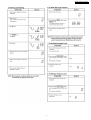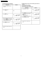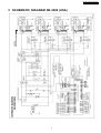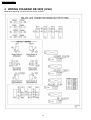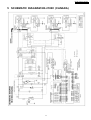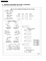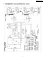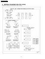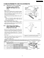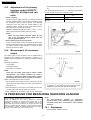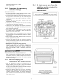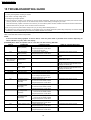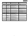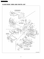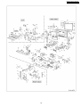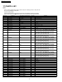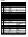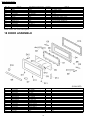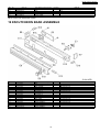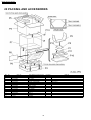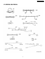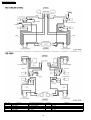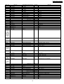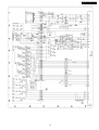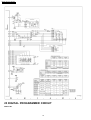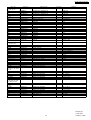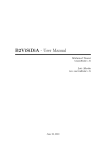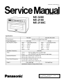
1
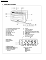
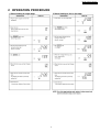
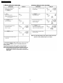
ORDER NO. MOD0108247C1
E10
Microwave Oven
NE-3280
NE-2180
NE-2180C
© 2001 Matsushita Electric Industrial Co., Ltd. All
rights reserved. Unauthorized copying and
distribution is a violation of law.
NE-3280 / NE-2180 / NE-2180C
CONTENTS
Page
Page
1 CONTROL PANEL
4
11 DISASSEMBLY AND PARTS REPLACEMENT
17
2 OPERATION PROCEDURE
5
12 COMPONENT TEST PROCEDURE
21
3 SCHEMATIC DIAGRAM NE-3280 (USA)
9
13 MEASUREMENTS AND ADJUSTMENTS
23
4 WIRING DIAGRAM NE-3280 (USA)
10
14 PROCEDURE FOR MEASURING RADIATION LEAKAGE
24
5 SCHEMATIC DIAGRAM NE-2180C (CANADA)
11
15 TROUBLESHOOTING GUIDE
26
6 WIRING DIAGRAM NE-2180C (CANADA)
12
16 EXPODED VIEW AND PARTS LIST
28
7 SCHEMATIC DIAGRAM NE-2180 (USA)
13
17 PARTS LIST
30
8 WIRING DIAGRAM NE-2180 (USA)
14
18 DOOR ASSEMBLE
34
9 DESCRIPTION OF OPERATING SEQUENCE
15
19 ESCUTCHEON BASE ASSEMBLE
35
20 PACKING AND ACCESSORIES
36
10 CAUTIONS TO BE OBSERVED WHEN TROUBLESHOOTING 16
2
NE-3280 / NE-2180 / NE-2180C
21 WIRING MATERIAL
37
22 DIGITAL PROGRAMMER CIRCUIT
40
23 DIGITAL PROGRAMMER CIRCUIT
3
42
NE-3280 / NE-2180 / NE-2180C
1 CONTROL PANEL
4
NE-3280 / NE-2180 / NE-2180C
2 OPERATION PROCEDURE
5
NE-3280 / NE-2180 / NE-2180C
6
NE-3280 / NE-2180 / NE-2180C
7
NE-3280 / NE-2180 / NE-2180C
8
NE-3280 / NE-2180 / NE-2180C
3 SCHEMATIC DIAGRAM NE-3280 (USA)
9
NE-3280 / NE-2180 / NE-2180C
4 WIRING DIAGRAM NE-3280 (USA)
NOTE: When replacing, check the lead wire colour as shown.
10
NE-3280 / NE-2180 / NE-2180C
5 SCHEMATIC DIAGRAM NE-2180C (CANADA)
11
NE-3280 / NE-2180 / NE-2180C
6 WIRING DIAGRAM NE-2180C (CANADA)
NOTE: When replacing, check the lead wire colour as shown.
12
NE-3280 / NE-2180 / NE-2180C
7 SCHEMATIC DIAGRAM NE-2180 (USA)
13
NE-3280 / NE-2180 / NE-2180C
8 WIRING DIAGRAM NE-2180 (USA)
NOTE: When replacing, check the lead wire colour as shown.
14
NE-3280 / NE-2180 / NE-2180C
9 DESCRIPTION OF OPERATING SEQUENCE
Variable power cooking control
shown in table.
The coil of power relays are energized intermittently by the
digital programmer circuit, when the oven is set at any power
selection except for High power position. The digital
programmer circuit controls the ON-OFF time of the power
relays contacts in order to vary the output power of the
microwave oven. The relation between indications on the
control panel and the output power of the microwave oven is as
NOTE:
9.1.
ON-OFF time of power relays are changed by digital
programmer circuit when remaining cooking time or
selected cooking time are within 8 minutes at MED,
LOW and Defrost cooking mode.
resulting in no microwave power.
Defrost control
NOTE:
When defrost power and defrosting time is selected and Start
pad is touched:
Defrost time selected is converted into seconds by the
DPC but display will show selected time in minutes and
seconds as programmed. The total number of seconds
is divided into 8 time periods. The remainder (seconds
not equally divisible by 8) are added to the last standing
time period.
1. The digital programmer circuit (DPC) divides the total
defrosting time into 8 equal periods, consisting of four
defrosting periods, each followed by a standing period.
(See figure)
2. During defrosting power periods, power relay ON-OFF time
is controlled at Low power mode by DPC.
3. During Standing periods, power relay is always open
15
NE-3280 / NE-2180 / NE-2180C
10 CAUTIONS TO BE OBSERVED WHEN
TROUBLESHOOTING
Unlike many other appliances, the microwave oven is highvoltage, high-current equipment. Though it is free from danger
in ordinary use, extreme care should be taken during repair.
10.3. When parts must be replaced,
remove the power plug from
the outlet.
CAUTION
Servicemen should remove their watches whenever working close to or
replacing the magnetron.
10.4. When the 15 Amp. (NE2180/NE-2180C) or 20 Amp.
(NE-3280) fuse is blown due to
the operation of interlock
monitor, replace the necessary
components according to the
following table.
10.1. Check the grounding
Do not operate on a 2-wire extension cord. The microwave
oven is designed to be used when grounded. It is imperative,
therefore, to make sure it is grounded properly before
beginning repair work.
10.2. Warning about the electric
charge in the high voltage
capacitor (
Figure).
For about 30 seconds after the oven is turned off, an electric
charge remains in the high voltage capacitor. When replacing
or checking parts, remove the power plug from the outlet and
short the terminal of the high voltage capacitor (terminal of lead
wire from diode) to chassis ground with and insulated handle
screwdriver or insulated jumper lead wire to discharge.
WARNING
There is high-voltage present, with high-current capabilities in the
circuits of the high voltage winding and filament winding of the high
voltage transformer. It is extremely dangerous to work on or near these
circuits with oven energized.
DO NOT measure the voltage in the high voltage circuit including
filament voltage of magnetron.
WARNING
Never touch any circuit wiring with your hand nor with an insulated tool
during operation.
10.5. Avoid inserting nails, wire, etc.
through any holes in the unit
during operation.
Never insert a wire, nail or any other metal object through the
lamp holes on the cavity or any other holes or gaps, because
such objects may work as an antenna and cause microwave
leakage.
16
NE-3280 / NE-2180 / NE-2180C
2. Make sure that all electrical connections are tight before
inserting the plug into the wall outlet.
10.6. Confirm after repair
1. After repair or replacement of parts, make sure that the
screws of the oven, etc. are neither loose nor missing.
3. Check for microwave energy leakage. (Refer to procedure
for measuring microwave energy leakage.)
11 DISASSEMBLY AND PARTS REPLACEMENT
CAUTION
Servicemen should remove their watches whenever working close to or
replacing the magnetron.
11.1. Magnetrons (Upper and
Lower)
Upper magnetrons (Right and Left)
1. Discharge electric charge remaining on the high voltage
capacitors.
2. Remove the entire rear panel by removing screws as shown
in figure.
3. Disconnect all lead wires from magnetron and thermal
cutout.
4. Remove the 4 screws holding magnetron.
5. Remove 2 screws holding thermal cutout.
6. Remove the mounting bracket from magnetron and install it
on the new magnetron.
Lower magnetrons (Right and Left)
1. Discharge electric charge remaining on the high voltage
capacitors.
2. Remove the entire rear panel by removing screws as shown
in figure.
3. Disconnect all lead wires from magnetron and thermal
cutout.
4. Remove the 4 screws holding magnetron.
5. Remove 2 screws holding thermal cutout.
6. Remove the air guide from magnetron and install it on the
new magnetron.
NOTE:
To prevent microwave leakage, tighten mounting
screws properly making sure there is no gap between
the waveguide and the magnetron.
CAUTION
When connecting 2 filament lead wires to the magnetron terminals, be
sure to connect the lead wires in the correct position. The lead wire
with blue connector should be connected to “FA terminal” and white
one should be connected to “F terminal”. (See Figure)
17
NE-3280 / NE-2180 / NE-2180C
NOTE:
Do not use a soldering iron or desoldering tool of
more than 30 watts on DPC contacts.
2. With all the terminal pins cleaned and separated from DPC
contacts, remove the defective transformer/power relays
and install new transformer/power relays making sure all
terminal pins are inserted completely. Resolder all terminal
contacts carefully.
11.4. Disassembly of door assembly
1. Detach the door spring ends from right and left door arms.
2. Remove the arm lever right and left by removing 2 screws
each on both sides.
3. Remove the sashes right and left by removing 1 screw each
on both sides.
4. By holding the door assembly, remove the right and left
sides door hinge pins. The door assembly is now free from
the oven.
5. Remove 3 screws holding the door A.
6. Remove the door C by using a flat screwdriver as figure.
7. Remove 4 screws holding door handle.
8. Separate door A and door E.
9. Remove the door arms by removing 1 pin each on both
sides.
11.2. Digital programmer circuit
board
1. Remove grounding screw for membrane switch and D.P.C.
ground.
2. Remove 2 screws holding control panel assembly to detach
it from main unit then remove connectors.
3. Remove 2 screws holding the D.P.C. board and remove the
board by freeing catch hooks.
NOTE:
Please use care in handling the power supply P.C.B.
and D.P.C. board to avoid damage.
11.3. Low voltage transformer
and/or power relays
NOTE:
Be sure to ground any static electric charge built up on
your body before handling the DPC.
1. Using solder wick or a desoldering tool and 30W soldering
iron, carefully remove all solder from the terminal pins of the
low voltage transformer and/or power relays.
18
NE-3280 / NE-2180 / NE-2180C
2. Remove 2 screws holding upper antenna assy by inserting
screwdriver through the opening on the antenna as shown
in figure.
11.6. Lower antenna (Right and
Left)
Lower antenna (Right and Left)
1. To remove the floor shelf, insert a screwdriver through the
openings on the right and left sides of the oven cavity and
carefully lift the floor shelf as shown in figure.
2. Remove 2 screws holding lower antenna assy by inserting
screwdriver through the opening on the antenna as shown
in figure.
11.5. Upper antenna (Right and Left)
Upper antenna (Right and Left)
1. Remove 8 plastic clips holding ceiling plate and exhaust
guides by using flat screwdriver or the like.
19
NE-3280 / NE-2180 / NE-2180C
Upper
Antenna
Motor
Lower
Antenna
Motor
PART NO.:
ANE61446030AP
(RATED: 120V)
PART NO.:
A6144-3280
(RATED: 120V)
11.9. Program, Beep and Program
Lock switches board.
(P.C.Board F assy)
1. Remove air filters.
2. Place the unit on its left side carefully.
3. Peel off panel B.
4. Remove 1 screw holding cover. (Figure)
5. Remove 2 screws holding switch assy.
6. Remove connector and remove 2 screws holding switch
board.
11.10. Voltage selection
(208V→
→230V)
1. Remove 1 screw holding voltage selection connector cover.
2. Plug the connector out from white (208V) socket and plug
the connector into the black (230V) socket.
11.7. Replacement of temperature
sensor (Thermal protector)
1. Cut 2 lead wires at the top of sensor terminals.
2. Remove 2 screws holding temp sensor and replace with
new one.
3. Solder the lead wires securely to the sensor terminals.
11.8. Replacement of antenna
motors (upper and lower)
1. The upper antenna motor may be removed by
disconnecting the lead wire connectors and removing its 2
mounting screws.
2. To remove the lower antenna motor, carefully place the unit
on its left side.
3. Remove the motor cover by removing 2 screws and follow
same procedure as for upper antenna.
CAUTION
There are two types of antenna motors. Therefore please replace with
correct one as showing below.
20
NE-3280 / NE-2180 / NE-2180C
12 COMPONENT TEST PROCEDURE
check continuity.
CAUTION
1. High voltage is present at the high voltage terminal of the high
voltage transformer during any cook cycle.
2. Normal (cold) resistance readings should be as follows:
· Secondary winding Approx. 40Ω — 100Ω
2. It is neither necessary nor advisable to attempt measurement of
the high voltage.
· Filament winding Approx. 0Ω
3. Before touching any oven components, or wiring, always unplug
the oven from its power source and discharge the high voltage
capacitor.
· Primary winding Approx. 0Ω — 3Ω
12.4. High voltage capacitor
12.1. Primary Interlock Switch
(SAFETY SWITCH A),
Secondary Interlock Switch
(SAFETY SWITCH B) and
Power Relay
1. Check continuity of capacitor with meter on highest OHM
scale.
2. A normal capacitor will show continuity for a short time, and
then indicate 9MΩ once the capacitor is charged.
3. A shorted capacitor will show continuous continuity.
4. An open capacitor will show constant 9MΩ.
5. Resistance between each terminal and chassis should be
infinite.
1. Unplug the power cable.
2. Unplug lead wire connectors to Power Relay (RY2-16) and
verify continuity of the power relay terminals.
12.5. Magnetron
3. Unplug lead wire connectors to Primary Interlock Switch
and Secondary Interlock Switch.
Continuity checks can only indicate an open filament or a
shorted magnetron. To diagnose for an openfilament or
shorted magnetron.
4. Test the continuity of switches with the door in both open
and closed positions with ohm meter (low scale). Normal
continuity readings should be as follows.
Door Opened
Primary
Interelock Ω (open)
Switch
Secondary
Interlock Ω (open)
Switch
Ω (open)
Power Relays
1. Isolate magnetron from the circuit by disconnecting the
leads.
Door Closed
0Ω (close)
2. A continuity check across magnetron filament terminals
should indicate one ohm or less.
0Ω (close)
3. A continuity check between each filament terminal and
magnetron case should read open.
0Ω (close)
12.2. Short/Monitor Switch (Both
Right and Left)
NO Terminals
NC Terminals
Door Opened
Ω (open)
0Ω (close)
Door Closed
0Ω (close)
Ω (open)
12.3. High voltage transformer
1. Remove connections from the transformer terminals and
21
NE-3280 / NE-2180 / NE-2180C
12.7. Membrane key board
(Membrane switch assembly)
Check continuity between switch terminals, by tapping an
appropriate pad on the key board. The contacts assignment of
the respective pads on the key board is as shown in digital
programmer circuit.
12.8. Protector diode
1. Isolate the protector diode assembly from the circuit by
disconnecting its leads.
2. With the ohmmeter set on the highest resistance scale,
measure the resistance across the protector diode
terminals. Reverse the meter leads and again observe the
resistance reading. A normal protector diode’s resistance
will be infinite in both directions. It is faulty if it shows
continuity in one or both directions.
12.9. Temp sensor (Thermal
protector)
A temp sensor is mounted on exhaust guide. Its purpose is to
automatically shut off the oven in case the cavity overheats for
any reason.
The thermal protector will operate at 257°F (125°C).
The device is connected to the DPC on touch control models.
When the thermal protector exceeds its temperature it will turn
off the power to oven cavity and display will go to reset mode.
The cooking program can be reset after cool-down.
THERMISTOR RESISTANCE VALUE
30K — 120K at 10°C — 30°C (50°F — 86°F)
12.6. Diode
1. Isolate the diode from the circuit by disconnecting the leads.
2. With the ohmmeter set on the highest resistance scale,
measure the resistance across the diode terminals.
Reverse the meter leads and again observe the resistance
reading. Meter with 6V, 9V or higher voltage batteries
should be used to check the front-to-back resistance of the
diode, otherwise an infinite resistance may be read in both
directions. A normal diode’s resistance will be infinite in one
direction and several hundred kΩ in the other direction.
22
NE-3280 / NE-2180 / NE-2180C
13 MEASUREMENTS AND ADJUSTMENTS
13.1. Adjustment of the secondary
interlock switch (SAFETY
SWITCH B) (Right and Left
side)
1. Switch operation
When the door is slightly opened, the secondary interlock
switch opens the main circuit. The movement of the door
from the closed position to the operation position (shown as
liter) of the switch when it opens the main circuit, must
maintain within following tolerances.
SECONDARY INTERLOCK SEITCH (liter) = 3 mm — 5 mm
(When secondary interlock switch opens the main circuit)
NOTE:
Make sure that primary interlock switch turns off
prior to the secondary interlock switch when the
door is gradually opened.
2. How to adjust secondary interlock switch
Loosen 2 screws which secure the secondary interlock
switch bracket to the bracket of the oven assembly and then
adjust the secondary interlock switch bracket by moving it to
either direction as shown in figure.
13.2. Adjustment of the Short
Switch (MONITOR SWITCH)
(Right and Left side)
1. When the door is slightly opened, the Short Switch opens
the main circuit and closes the contacts for short circuit. The
movement of door from its closed position to open position
at which the Short Switch contacts open the main circuit
(shown as liter) must maintain within 8 mm — 11 mm and
at which the switch contacts close the short circuit should
be 20mm — 35 mm.
2. How to adjust
Loosen the 2 screws holding the short switch to the short
switch bracket, and then adjust the safety switch A by
moving it to either direction as shown in figure.
23
NE-3280 / NE-2180 / NE-2180C
with the thermometer and note the temperature. (Record as
T2)
13.3. Adjustment of the primary
interlock switch (SAFETY
SWITCH A) (Right and Left
side)
The normal temperature rise (T2 — T1) at High power position
for each models is as shown in following table.
Model
NE-3280
NE-2180
NE-2180C
1. Switch operation
When the door is slightly opened, the contacts of primary
interlock switch opened to give digital programmer circuit
the information that the door is opend. The allowable
movement of the door from the closed position to the
operating position (shown as liter) of the switch when it
opens the circuit, is specified as follows;
PRIMARY INTERLOCK SWITCH (liter) = 1 mm — 3 mm
(When primary interlock switch opens the circuit)
Temperature Rise (1 liter — 1
Min.)
Min. 27.4°C
Min 18°C
NOTE:
Make sure that primary interlock switch turn off
prior to the secondary interlock switch when the
door is gradually opened.
2. How to adjust primary interlock switch
Loosen 2 screws which secure the primary interlock switch
bracket to the bracket of the oven assembly and then adjust
the primary interlock switch bracket by moving it to either
direction as shown in figure.
13.4. Measurement of microwave
output
The output power of the magnetron can be determined by
performing IEC standard test procedures. However, it is
possible to test the magnetron by following procedure outlined
below.
Necessary equipement:
· 1 litre beaker
· Glass thermometer
· Wrist watch or stopwatch
NOTE:
Check the line voltage under load to ensure it meets
specifications. Low voltage condition will cause a
reduction in magnetron output. Temperature readings
and heating time, should be as accurate as possible.
Output power performance test procedure.
1. Fill the beaker with exactly one litre of tap water. Stir the
water using the thermometer and note the temperature.
(Record as T1)
2. Place the beaker in the center of cook plate. Set the oven
for High power and heat for exactly one minute.
3. After completion of the heating cycle, stir the water again
14 PROCEDURE FOR MEASURING RADIATION LEAKAGE
NOTE:
WARNING
Check for radiation leakage after every servicing.
Should the leakage be more than 2 mW/square centimeter
(1mW/square centimeter for Canada) infrorm PASC, PSC, or PCI
immediately. Aftr repairing or replacing any radiation safety device,
keep a written record for future reference, as required by D.H.H.S. and
Health and Welfare Canada regulation. This requirement must be
strictly observed. In addition, the leakage reading must be recorded on
the service repair ticket while in the customer’s home.
The
U.S.government
standard
is
5mw/square
centimeter while in the customer’s home. 2mw/square
centimeter stated here is Panasonic’s own voluntary
standard.
14.1. Equipment
· Electromagnetic radiation monitor
24
NE-3280 / NE-2180 / NE-2180C
· Glass thermometer 212°F or 100°C
14.4. At least once a year, have the
radiation monitor checked for
calibration by its
manufacturer.
· 600cc glass beaker
14.2. Procedure for measuring
radiation leakage
Note before measuring
1. Do not exceed meter full scale deflection Leakage monitor
should initially be set to the highest scale.
2. To prevent false readings the test probe should be held by
the grip portion of the handle only and moved along the
shaded area shown in Figure right no faster than 1 inch/sec
(2.5cm/sec)
3. Leakage with the outer
5mw/square centimeter
panel
removed
less
than
4. Leakage for a fully assembled oven with door normally
closed less than 2mw/square centimeter
5. Leakage for a fully assembled oven [Before the interlock
switch (primary) is interrupted] while pulling the door less
than 2mw/square centimeter
1. Pour 275±15cc (9ozs ±1/2oz) of 20 ± 5°C (68 ± 9°F) water
in a beaker which is graduated to 600cc, and place the
beaker in the center of the oven.
2. Set the radiation monitor to 2450MHz and use it following
the manufactuer’s recommended test procedure to assure
correct results.
3. When measuring the leakage, always use the 2 inch (5cm)
spacer supplied with the probe.
4. Press the start button and with the magnetron oscillating,
measure the leakage by holding the probe perpendicular to
the surface being measured.
1. Measurement with the outer panel removed.
Whenever you replace the magnetron, measure for
radiation leakage before the outer panel is installed and
after all necessary components are replaced or adjusted.
Special care should be taken in measuring around the
magnetron.
WARNING
Avoid contacting any high voltage parts.
2. Measurements with a fully assembled oven.
After all components, including the outer panel are fully
assembled, measure for radiation leakage around the door
periphery, the door viewing window, the exhaust opening
and air inlet openings.
14.3. Record keeping and
notification after measurement
1. After any adjustment or repair to a microwave oven, a
leakage reading must be taken. Record this leakage
reading on the repair ticket even if it is zero.
A copy of this repair ticket and the microwave leakage
reading should be kept by repair facility.
2. Should the radiation leakage be more than 2mw/square
centimeter after determining that all parts are in good
condition, functioning properly, and genuine replacement
parts as listed in this manual have been used, immediately
notify PASC or PSC.
25
NE-3280 / NE-2180 / NE-2180C
15 TROUBLESHOOTING GUIDE
CAUTION
1. Check grounding before checking for trouble.
2. Be careful of the high voltage circuit.
3. Discharge high voltage capacitor.
4. When checking the continuity of the switches or the high voltage transformer, disconnect one lead wire from these parts and then check
continuity with the AC plug removed. To do otherwise may result in a false reading or damage to your meter.
When disconnecting a plastic connector from a terminal, you must hold the plastic connector instead of the lead wire and then disconnect it,
otherwise lead wire may be open or the connector cannot be removed.
5. Be sure to ground any static electric charge built up in your body, before handling the D.P.C.
6. A 208-230V AC is present at the shaded area ( ) of the power supply circuit board (Terminals of power relays and primary circuit of low voltage
transformer). When troubleshooting, be cautious of possible electrical shock hazard.
First of all operate the microwave oven following the correct operating procedures described on pages 4 of this service manual in
order to find the exact cause of any trouble.
NOTE:
If the unit shows faulty symptom as shown below, check the parts listed in possible cause column depending on
failure indication e.g. F81, F82 in the display.
[TROUBLE] Oven does not operate at all or oven does not start cooking. NE-3280
DISPLAY
F33
F34
CONDITIONS
Open temperature
sensor (exhaust)
Short temperature
sensor (exhaust)
F44
POSSIBLE CAUSE
1. Temperature sensor failure
2. Digital programmer circuit failure
3. Loose connector CN5
1. Temperature sensor failure
2. Digital programmer circuit failure
1. Shorted membrane switch
F01
(With continuous
beep sounds)
F03
Exhaust temperature
exceeds 120°C
1. Burning food in the oven due to over cook
Input voltage exceed
+ 12.5%
1. Increase in power source voltage
F04
Input voltage is less
than — 12.5%
1. Decrease in power source voltage
Memory failure
1.25A fuse blown
1.25A fuse is OK
1. Digital programmer circuit failure
1. Low-Voltage transformer failure
1. Thermal cutout failure
F05
No display
No display
TIMING OF FAILURE INDICATION
It is appeared when failure occured.
It is appeared when failure occured.
It is appeared 2 minutes after failure
occured.
It is appeared when exhaust temperature
exceeds above 120°C.
It is appeared when the unit is plugged in.
Note that it returns normal operation mode
by tapping the STOP pad.
It is appeared when the unit is plugged in.
Note that it returns normal operation mode
by tapping the STOP pad.
2. Low voltage transformer failure
F81
F82
F83
F84
F86
F87
F88
No voltage supply to
high voltage trans.
(lower/left)
No voltage supply to
high voltage trans.
(lower/right)
No voltage supply to
high voltage trans.
(upper/left)
No voltage supply to
high voltage trans.
(upper/right)
Shorted contacts of RY3
Shorted contacts of RY5
Shorted contacts of RY7
3. Digital programmer circuit failure
1. Relay failure RY-3 (A)
It is appeared when failure occured.
2. Loose connector CN256, CN257
3. Digital programmer circuit failure
1. Relay failure RY-5 (B)
It is appeared when failure occured.
2. Loose connector CN258, CN259
3. Digital programmer circuit failure
1. Relay failure RY-7 (C)
It is appeared when failure occured.
Loose connector CN260, CN261
2. Digital programmer circuit failure
1. Relay failure RY-9 (C)
It is appeared when failure occured.
Loose connector CN262, CN263
2. Digital programmer circuit failure
1. Relay failure RY-3 (A)
It is appeared when failure occured.
2. Digital programmer circuit failure
1. Relay failure RY-5 (B)
It is appeared when failure occured.
2. Digital programmer circuit failure
1. Relay failure RY-7 (C)
It is appeared when failure occured.
2. Digital programmer circuit failure
26
NE-3280 / NE-2180 / NE-2180C
DISPLAY
F89
CONDITIONS
Shorted contacts of RY9
POSSIBLE CAUSE
1. Relay failure RY-9 (D)
TIMING OF FAILURE INDICATION
It is appeared when failure occured.
2. Digital programmer circuit failure
[TROUBLE] Oven does not operate at all or oven does not start cooking. NE-2180, NE-2180C
DISPLAY
F33
F34
CONDITIONS
Open temperature
sensor (exhaust)
Short temperature
sensor (exhaust)
F44
POSSIBLE CAUSE
1. Temperature sensor failure
2. Digital programmer circuit failure
3. Loose connector CN5
1. Temperature sensor failure
2. Digital programmer circuit failure
1. Shorted membrane switch
F01
(With continuous
beep sounds)
F03
Exhaust temperature
exceeds 120°C
1. Burning food in the oven due to over cook
Input voltage exceed
+ 12.5%
1. Increase in power source voltage
F04
Input voltage is less
than — 12.5%
1. Decrease in power source voltage
Memory failure
1.25A fuse blown
1.25A fuse is OK
1. Digital programmer circuit failure
1. Low-Voltage transformer failure
1. Thermal cutout failure
F05
No display
No display
TIMING OF FAILURE INDICATION
It is appeared when failure occured.
It is appeared when failure occured.
It is appeared 2 minutes after failure
occured.
It is appeared when exhaust temperature
exceeds above 120°C.
It is appeared when the unit is plugged in.
Note that it returns normal operation mode
by tapping the STOP pad.
It is appeared when the unit is plugged in.
Note that it returns normal operation mode
by tapping the STOP pad.
2. Low voltage transformer failure
F81
F84
F86
F89
No voltage supply to
high voltage
transformer. (left)
No voltage supply to
high voltage
transformer. (right)
Shorted contacts of RY3
Shorted contacts of RY9
3. Digital programmer circuit failure
1. Relay failure RY-3 (A)
It is appeared when failure occured.
2. Loose connector CN256, CN257
3. Digital programmer circuit failure
1. Relay failure RY-9 (C)
It is appeared when failure occured.
2. Loose connector CN262, CN257
3. Digital programmer circuit failure
1. Relay failure RY-3 (A)
It is appeared when failure occured.
2. Digital programmer circuit failure
1. Relay failure RY-9 (D)
It is appeared when failure occured.
2. Digital programmer circuit failure
27
NE-3280 / NE-2180 / NE-2180C
16 EXPODED VIEW AND PARTS LIST
28
NE-3280 / NE-2180 / NE-2180C
29
NE-3280 / NE-2180 / NE-2180C
17 PARTS LIST
NOTE
When ordering replacement part(s), please use part number(s) shown in this parts list.
Do not use description of the part.
Importan safety notice:
Components identified by
mark have special characteristics important for safety.
When replacing any of these components, use only manufacturere’s specified parts.
Ref. No.
Part No.
1
ANE00068U0CP
1
A00063040AP
2
A00333A40AP
2
A00333570CP
3
A010T3030GP
4
A02393A80BP
5
A05243A40AP
5
A05243A60AP
5
A05243A60CP
6
ANE6595P40AP
6
ANE6230P30AP
7
ANE0911000DC
7
ANE0911000DC
8
ANE0911000DF
9
XYD4+EE12F
Part Name & Description
CAUTION LABEL
CAUTION LABEL
FUSE LABEL
FUSE LABEL
SHELF
CORD LABEL
NAME LABEL
NAME LABEL
NAME LABEL
FUSE
FUSE
CUSHION RUBBER B
CUSHION RUBBER B
CUSHION RUBBER B
SCREW
Pcs/Set
1
1
1
1
1
1
1
1
1
2
2
1
1
1
19
9
XYD4+EE12F
SCREW
18
9
XYD4+EE12F
SCREW
19
9
XYD4+EE12F
SCREW
19
9
XYD4+EE12F
SCREW
19
9
XYD4+EE12F
SCREW
19
9
XYD4+EE12F
SCREW
19
9
XYD4+EE12F
SCREW
19
9
XYD4+EE12F
SCREW
19
9
XYD4+EE12F
SCREW
19
9
XYD4+EE12F
SCREW
19
10
11
11
11
11
12
12
13
13
13
13
14
15
15
15
15
15
15
15
15
ANE0911000EG
ANE0911000EH
ANE0911000EH
ANE0911000EH
ANE0911000EH
ANE0911000MG
ANE0911000MG
ANE0917000EB
ANE0917000EB
ANE0917000EB
ANE0917000EB
ANE0921000CG
ANE000Z000AA
ANE000Z000AA
ANE000Z000AA
ANE000Z000AA
ANE000Z000AA
ANE000Z000AA
ANE000Z000AA
ANE000Z000AA
CUSHION
CUSHION
CUSHION
CUSHION
CUSHION
CUSHION
CUSHION
CUSHION
CUSHION
CUSHION
CUSHION
CUSHION
CUSHION
CUSHION
CUSHION
CUSHION
CUSHION
CUSHION
CUSHION
CUSHION
RUBBER
RUBBER
RUBBER
RUBBER
RUBBER
RUBBER
RUBBER
RUBBER
RUBBER
RUBBER
RUBBER
RUBBER
RUBBER
RUBBER
RUBBER
RUBBER
RUBBER
RUBBER
RUBBER
RUBBER
B
B
B
B
B
B
B
B
B
B
B
C
C
C
C
C
C
C
C
C
2
2
4
2
2
2
2
2
2
2
2
1
14
14
14
14
14
14
14
14
30
Remarks
NE-2180C
NE-3280,NE-2180
NE-3280,NE-2180
NE-2180C
NE-3280,NE-2180
NE-3280
NE-2180
NE-2180C
NE-2180(C)(15A)
NE-3280(20A)
NE-3280
NE-3280
NE-2180(C)(4X12) (FOR TERMINAL PLATE ANTENNA,
MOTOR COVER,SWITCH HOLDER,DIODE,
CAPACITOR BRACKET,ESCUTCHEON BASE,DPC EARTH)
NE-3280(FOR TERMINAL PLATE ANTENNA,
MOTOR COVER ,SWITCH HOLDER,DIODE,
CAPACITOR BRACKET,ESCUTCHEON BASE,DPC EARTH)
NE-2180(C)(4X12) (FOR TERMINAL PLATE ANTENNA,
MOTOR COVER,SWITCH HOLDER,DIODE,
CAPACITOR BRACKET,ESCUTCHEON BASE,DPC EARTH)
NE-2180(C)(4X12) (FOR TERMINAL PLATE ANTENNA,
MOTOR COVER,SWITCH HOLDER,DIODE,
CAPACITOR BRACKET,ESCUTCHEON BASE,DPC EARTH)
NE-2180(C)(4X12) (FOR TERMINAL PLATE ANTENNA,
MOTOR COVER,SWITCH HOLDER,DIODE,
CAPACITOR BRACKET,ESCUTCHEON BASE,DPC EARTH)
NE-2180(C)(4X12) (FOR TERMINAL PLATE ANTENNA,
MOTOR COVER,SWITCH HOLDER,DIODE,
CAPACITOR BRACKET,ESCUTCHEON BASE,DPC EARTH)
NE-2180(C)(4X12) (FOR TERMINAL PLATE ANTENNA,
MOTOR COVER,SWITCH HOLDER,DIODE,
CAPACITOR BRACKET,ESCUTCHEON BASE,DPC EARTH)
NE-2180(C)(4X12) (FOR TERMINAL PLATE ANTENNA,
MOTOR COVER,SWITCH HOLDER,DIODE,
CAPACITOR BRACKET,ESCUTCHEON BASE,DPC EARTH)
NE-2180(C)(4X12) (FOR TERMINAL PLATE ANTENNA,
MOTOR COVER,SWITCH HOLDER,DIODE,
CAPACITOR BRACKET,ESCUTCHEON BASE,DPC EARTH)
NE-2180(C)(4X12) (FOR TERMINAL PLATE ANTENNA,
MOTOR COVER,SWITCH HOLDER,DIODE,
CAPACITOR BRACKET,ESCUTCHEON BASE,DPC EARTH)
NE-2180(C)(4X12) (FOR TERMINAL PLATE ANTENNA,
MOTOR COVER,SWITCH HOLDER,DIODE,
CAPACITOR BRACKET,ESCUTCHEON BASE,DPC EARTH)
NE-2180(C)
NE-3280
NE-2180(C)
NE-2180(C)
NE-3280
NE-3280
NE-3280 / NE-2180 / NE-2180C
Ref. No.
Part No.
15
ANE000Z000AA
15
ANE000Z000AA
15
ANE000Z000AA
15
ANE000Z000AA
16
ANE0922000JE
17
ANE000Z000AB
17
ANE000Z000AB
17
ANE000Z000AB
18
ANE0924000AB
18
ANE0924000AB
19
A100A3560BP
20
A100Q3560GP
21
A10083030GP
21
A10083030GP
22
A10093030GP
23
A10133030GP
24
A10143030GP
25
A10203030GP
26
A10263030GP
27
A10283030GP
27
A10283030GP
28
A10503030GP
29
A10583560GP
30
A10593560GP
31
A10943030GP
31
A10943030GP
32
ANE11548U0AP
33
A11743060GP
34
A16163040AP
35
A200A3A40AP
36
A200P3030GP
37
A200Q3030GP
38
A20103030GP
39
A20113030GP
40
A20193030GP
40
A20193030GP
40
A20193030GP
40
A20193030GP
40
A20193030GP
40
A20193030GP
40
A20193030GP
40
A20193030GP
41
A202R3560GP
41
A202R3560GP
42
A22173030GP
43
A22183030GP
43
A22183030GP
44
A22193030GP
44
A22193030GP
45
ANE3008P00RN
45
ANE3008P00RN
46
XWNANE53GV
47
A30203030GP
47
A30203030GP
48
ANE3033-560
48
ANE3033-560
49
ANE3034-560
49
ANE3034-560
50
A31123050GP
50
A31123030GP
51
A31363030GP
51
A31363030GP
52
ANE3155-610
52
ANE3155-610
53
ANE3157-610
53
ANE3157-610
54
A31863A40BP
54
A31863A60BP
54
A31863A60CP
55
A32493030GP
55
A32493030GP
56
A32523030GP
56
A32523030GP
57
A33373030GP
Part Name & Description
CUSHION RUBBER C
CUSHION RUBBER C
CUSHION RUBBER C
CUSHION RUBBER C
CUSHION RUBBER C
CUSHION RUBBER C
CUSHION RUBBER C
CUSHION RUBBER C
CUSHION RUBBER C
CUSHION RUBBER C
BASE
BACK PANEL
RUBBER FOOT
RUBBER FOOT
CABINET BODY(U)
LEFT SIDE SASH
RIGHT SIDE SASH
SASH RUBBER B
LAMP COVER
ANTENNA MOTOR COVER
ANTENNA MOTOR COVER
SASH RUBBER A
BACK PANEL COVER A
BACK PANEL COVER B
RUBBER FOOT B
RUBBER FOOT B
BACK PANEL COVER
SPACER
PANEL B(U)
OVEN
ROLLER BRACKET A
ROLLER BRACKET B
CEILING PLATE B
CEILING PLATE
ANTENNA STOPPER
ANTENNA STOPPER
ANTENNA STOPPER
ANTENNA STOPPER
ANTENNA STOPPER
ANTENNA STOPPER
ANTENNA STOPPER
ANTENNA STOPPER
ANTENNA(U)
ANTENNA(U)
BARRIER SHEET A
BARRIER SHEET B
BARRIER SHEET B
BARRIER SHEET C
BARRIER SHEET C
HINGE PIN
HINGE PIN
SPACER
DOOR HOOK A
DOOR HOOK A
DOOR ROLLER PIN
DOOR ROLLER PIN
DOOR GUIDE ROLLER
DOOR GUIDE ROLLER
DOOR HOOK B
DOOR HOOK B
HOOK SPACER A
HOOK SPACER A
SPRING
SPRING
PACKING RUBBER
PACKING RUBBER
DOOR PANEL
DOOR PANEL
DOOR PANEL
DOOR SWITCH LEVER
DOOR SWITCH LEVER
DOOR ARM SPACER
DOOR ARM SPACER
DOOR ARM LEVER
31
Pcs/Set
14
14
14
14
1
2
2
2
2
2
1
1
2
2
1
1
1
1
1
2
2
1
1
1
2
2
1
1
1
1
1
1
2
1
8
8
8
8
8
8
8
8
4
4
1
2
2
1
2
2
2
1
2
2
2
2
2
2
2
2
2
2
2
2
2
2
1
1
1
2
2
2
2
2
Remarks
(NOTE)
LEFT
RIGHT
RIGHT
LEFT
NE-3280
NE-3280
NE-2180(C)
NE-3280
NE-2180(C)
NE-3280
NE-3280
NE-2180
NE-2180C
NE-3280 / NE-2180 / NE-2180C
Ref. No.
Part No.
57
A33373030GP
58
A400B3040AP
59
A400C3040AP
60
A402N3030GP
61
A40253030GP
61
A40253030GP
62
A40263030GP
63
A40313030GP
64
A40423040AP
64
A40423040AP
65
A40473560GP
66
A40923030GP
66
A40923030GP
67
A40963030GP
68
ANE42408U0AP
68
ANE42408U0AP
69
A490W3570AP
69
A490W3590AP
70
A490Y3570AP
70
A490Y3590AP
71
ANE50328U0AP
71
ANE50328U0AP
72
A622A3A40AP
72
A622A3A60AP
72
A622A3A40AP
72
A622A3A40AP
73
A600E3030GP
73
A600E3030BP
74
A600S3030GP
74
A600S3A40BP
75
A601L4000AP
76
A603M3560BP
76
A603M3580GP
77
A603Y3570AP
78
A60304080BP
79
ANE6040-730
80
A61143040AP
80
A61143040AP
81
A605Q3030GP
82
A605S3030GP
83
2M210-M1GL
83
2M244-M1GL
83
2M210-M1GL
83
2M210-M1GL
84
A60733030GP
85
A60903050GP
85
A63903330GP
86
A61073030GP
87
ANE6142-F60
Part Name & Description
DOOR ARM LEVER
AIR FILTER FLAME(U)
EXHAUST GUIDE B
EXHAUST GUIDE A
AIR GUIDE A
AIR GUIDE A
AIR GUIDE B
AIR GUIDE C
AIR GUIDE F
AIR GUIDE F
AIR GUIDE E
FILTER HANDLE
FILTER HANDLE
INSULATION SHEET
FILTER HANDLE B
FILTER HANDLE B
FAN MOTOR A
FAN MOTOR A
FAN MOTOR B
FAN MOTOR B
MAGNETRON BRACKET
MAGNETRON BRACKET
H.V.TRANSFORMER
H.V.TRANSFORMER
H.V.TRANSFORMER
H.V.TRANSFORMER
TERMINAL PLATE
TERMINAL PLATE
CAPACITOR BRACKET
CAPACITOR BRACKET
TEMP SENSOR
P.C. BOARD B(U)
P.C. BOARD B(U)
L.V.TRANSFORMER(U)
INCANDESCENT LAMP
OVEN LAMP SHEET
MOUNTING BRACKET
MOUNTING BRACKET
PUSH SWITCH
PC BOARD H(U)
MAGNETRON
MAGNETRON
MAGNETRON
MAGNETRON
OVEN LAMP COVER
H.V.CAPACITOR
H.V.CAPACITOR
PARTS BRACKET B
MICROSWITCH
2
2
1
1
2
2
1
1
2
2
1
2
2
1
2
2
1
1
1
1
2
2
4
2
4
4
1
1
2
2
1
1
1
1
1
2
1
1
1
1
4
4
4
4
1
4
4
1
2
87
A61423030GP
MICROSWITCH
2
88
88
89
89
90
91
92
92
93
93
93
93
94
95
96
97
98
98
99
100
101
101
A61424L0AG
A61424L0AG
A6144-3280
A6144-3280
A61446030AP
A61454000AP
A61454050AP
A61454050AP
A61453570CP
A61453570CP
A61453570CP
A61453570CP
A61524210AA
A61583030GP
A61583050GP
A61703030GP
A6202-3280
A62024000AP
A62303A60BP
A6231-F50
A62383030GP
A62383030GP
MICROSWITCH
MICROSWITCH
ANTENNA MOTOR
ANTENNA MOTOR
ANTENNA MOTOR
THERMAL CUTOUT
THERMAL CUTOUT
THERMAL CUTOUT
THERMAL CUTOUT
THERMAL CUTOUT
THERMAL CUTOUT
THERMAL CUTOUT
SOCKET
DOOR SWITCH A
DOOR SWITCH B
INSULATION SHEET B
DIODE,SI
DIODE,SI
FUSE
FUSE HOLDER
SPACER
SPACER
2
2
2
2
2
1
2
2
4
4
4
4
1
1
1
1
4
4
1
1
2
2
32
Pcs/Set
Remarks
NE-3280
NE-2180(C)
NE-3280
NE-2180(C)
NE-3280
NE-2180(C)
NE-3280
NE-3280
NE-2180(C)
NE-3280
NE-3280
NE-2180(C)
240V/20W
NE-2180(C)
NE-3280
NE-2180(C)
NE-2180(C)
NE-2180(C)(0.63MF,AC2700V)
NE-3280(1.0MF,AC2700V)
NE-2180(C)
V-15G-3C26(SECONDARY INTERLOCK SWITCH)
NE-3280(A20G7-3C108)
SECONDARY LATCH SWITCH
V-15G-3C26(PRIMARY INTERLOCK SWITCH)
V-15G-3C26(PRIMARY INTERLOCK SWITCH)
LOWER(2.5W)
LOWER(2.5W)
UPPER(2.5W)
FOR OVEN
FOR ANTENNA MOTOR
FOR ANTENNA MOTOR
FOR MAGNETRON
FOR MAGNETRON
FOR MAGNETRON
FOR MAGNETRON
RIGHT(MONITOR SWITCH)
LEFT(MONITOR SWITCH)
NE-3280
NE-2180(C)
NE-2180C(30A)
NE-2180C
NE-3280 / NE-2180 / NE-2180C
Ref. No.
Part No.
102
XYN5+C8BN
103
A64083040AP
103
A64083040AP
104
A65313030GP
105
ANE64086Q0AP
106
A65513030GP
106
A65513030GP
107
A65613030GP
108
A05103040AP
108
A05103570CP
109
A65953170GP
110
A66033040AP
111
A66263040AP
112
A692Y3570AP
112
A692Y3570CP
113
ANE01728U0CP
113
ANE01728U0CP
114
A83613030GP
115
A900C3A40AP
115
B900C3570AP
116
XTC4+10FC
117
XYN4+F18S
117
XYN4+F18S
118
XYN4+F12S
118
XYN4+F12S
119
ANE9080-730
119
ANE9080-730
119
ANE9080-730
119
ANE9080-730
119
ANE9080-730
120
ANE90828U0AP
120
ANE90828U0AP
121
ANE9082930AP
121
ANE9082930AP
121
ANE9082930AP
121
ANE9082930AP
121
ANE9082930AP
121
ANE9082930AP
122
A98363030GP
123
A02433560GP
124
XST4+6VS
124
XST4+6VS
124
XST4+6VS
124
XST4+6VS
124
XST4+6VS
124
XST4+6VS
125
XTC4+10BC
125
XTC4+10BC
125
XTC4+10BC
125
XTC4+10BC
125
XTC4+10BC
125
XTC4+10BC
126
XTC4+12BK
126
XTC4+12BK
127
XTEANE5+10B
127
XTEANE5+10B
128
XTWANE4+10RU
128
XTWANE4+10RU
128
XTWANE4+10RU
128
XTWANE4+10RU
129
A608E3560GP
130
ANE0962000ZE
131
A80163060GP
132
ANE0961000ZL
132
ANE0961000ZL
133
ANE0963000AS
134
A10493030GP
134
A10493030GP
135
A18593560GP
136
A91433040AP
136
A91433040AP
136
A91433040AP
137
XNW5EFN
137
XNW5EFN
Part Name & Description
SCREW
WASHER
WASHER
SWITCH HOLDER
WASHER
H.V.T.MOUNTING
H.V.T.MOUNTING
BUZZER CASE
CAUTION LABEL
CAUTION LABEL
FUSE B
OVEN LAMP BRACKET
THERMAL CUTOUT MOUNT
NOISE FILTER(U)
NOISE FILTER(U)
CAUTION LABEL
CAUTION LABEL
SWITCH SPACER
AC CORD W/PLUG(U)
AC CORD W/PLUG(U)
SCREW
SCREW
SCREW
SCREW
SCREW
CLIP(YELLOW)
CLIP(YELLOW)
CLIP(YELLOW)
CLIP(YELLOW)
CLIP(YELLOW)
CLIP(BLACK)
CLIP(BLACK)
CLIP
CLIP
CLIP
CLIP
CLIP
CLIP
CASE
TERMINAL LABEL
SCREW
SCREW
SCREW
SCREW
SCREW
SCREW
SCREW
SCREW
SCREW
SCREW
SCREW
SCREW
SCREW
SCREW
SCREW
SCREW
SCREW
SCREW
SCREW
SCREW
P.C. BOARD Q
CUSHION RUBBER D
CUSHION SPACER
CUSHION RUBBER D
CUSHION RUBBER D
CUSHION RUBBER D
CUSHION RUBBER
CUSHION RUBBER
SHELF SUPPORT
CLIP A
CLIP A
CLIP A
NUT
NUT
33
Pcs/Set
2
2
2
1
1
2
2
1
1
1
1
1
2
1
1
1
1
1
1
1
4
4
4
4
2
3
2
2
2
2
2
8
8
8
8
8
8
1
1
8
8
8
8
8
8
9
9
9
9
9
9
3
3
4
4
8
8
8
8
1
2
1
2
2
2
2
2
2
4
4
4
2
2
Remarks
NE-3280(5X8)FOR NOISE FILTER
NE-3280,NE-2180
NE-2180C
(1.25A)
NE-3280,NE-2180
NE-2180C
NE-3280
NE-2180(C)
4X10(FOR ESCUTCHEON BASE)
4X18(FOR DOOR HOOK B)
4X18(FOR DOOR HOOK B)
4X12(FOR DOOR SWITCH)
4X12(FOR DOOR SWITCH)
NE-2180(C)
NE-3280
NE-2180(C)
NE-2180(C)
NE-2180(C)
NE-3240,NE-2140
4X6(FOR ANTENNA)
4X6(FOR ANTENNA)
4X6(FOR ANTENNA)
4X6(FOR ANTENNA)
4X6(FOR ANTENNA)
4X6(FOR ANTENNA)
4X10(FOR CABINET BODY LAMP
4X10(FOR CABINET BODY LAMP
4X10(FOR CABINET BODY LAMP
4X10(FOR CABINET BODY LAMP
4X10(FOR CABINET BODY LAMP
4X10(FOR CABINET BODY LAMP
4X12(FOR BASE)
4X12(FOR BASE)
5X10(FOR ROLLER BRACKET)
5X10(FOR ROLLER BRACKET)
4X10(FOR LOWER MAGNETRON)
4X10(FOR LOWER MAGNETRON)
4X10(FOR LOWER MAGNETRON)
4X10(FOR LOWER MAGNETRON)
NE-3280
NE-2180(C)
NE-2180(C)
NE-2180(C)
FOR SHELF SUPPRT
FOR SHELF SUPPRT
COVER
COVER
COVER
COVER
COVER
COVER
SASH)
SASH)
SASH)
SASH)
SASH)
SASH)
NE-3280 / NE-2180 / NE-2180C
Ref. No.
Part No.
138
XWG5BV
138
XWG5BV
139
A90273A40AP
139
A90273040AP
140
A90353A40AP
140
A90353570CP
141
XTT4+8E
142
XYEANE5+C16T
142
XYEANE5+C16T
142
XYEANE5+C16T
142
XYEANE5+C16T
143
A30183030GP
143
A30183030GP
144
A04115020CQ
Part Name & Description
WASHER
WASHER
CORD BUSHING
CORD BUSHING
CORD BRACKET
CORD BRACKET
SCREW
SCREW
SCREW
SCREW
SCREW
DOOR KEY A
DOOR KEY A
CSA LABEL
Pcs/Set
2
2
1
1
1
1
1
8
8
8
8
2
2
1
Remarks
FOR SHELF SUPPRT
FOR SHELF SUPPRT
NE-3280
NE-2180(C)
NE-3280
NE-2180(C)
4X8(FOR BACK PANEL COVER)
5X16(FOR UPPER MAGNETRON)
5X16(FOR UPPER MAGNETRON)
5X16(FOR UPPER MAGNETRON)
5X16(FOR UPPER MAGNETRON)
NE-2180C
NOTE: Please order name label together.
18 DOOR ASSEMBLE
Ref. No.
Part No.
D1
A30033030GP
D2
A30043030GP
D2
A30043030GP
D3
A301A3030GP
D4
A302K3030GP
D5
ANE3009P00RN
D5
ANE3009P00RN
D6
ANE3036P00RN
D6
ANE3036P00RN
D7
A30703030GP
D8
A31343030GP
D9
A31463030GP
D10
A31473030GP
D11
XTC4+10BC
D11
XTC4+10BC
D11
XTC4+10BC
Part Name & Description
DOOR FRAME
DOOR ARM
DOOR ARM
DOOR A
DOOR E(U)
DOOR SPRING
DOOR SPRING
DOOR ARM PIN
DOOR ARM PIN
HANDLE PIECE A
HANDLE PIECE B
DOOR SCREEN B
HANDLE SHEET C
SCREW
SCREW
SCREW
34
Pcs/Set
1
2
2
1
1
2
2
2
2
1
1
1
1
3
3
3
Remarks
NOTE
4X10
4X10
4X10
NE-3280 / NE-2180 / NE-2180C
Ref. No.
Part No.
D12
XYEANE4+C16T
D12
XYEANE4+C16T
D13
A30853030GP
D14
ANE0245X00AP
D15
ANE01728U0CP
Part Name & Description
SCREW
SCREW
DOOR C
DHHS LABEL
CAUTION LABEL
Pcs/Set
4
4
1
1
1
Remarks
4X16
4X16
NE-3280,NE2180
NOTE: Please order DHHS label together.
19 ESCUTCHEON BASE ASSEMBLE
Ref. No.
Part No.
E1
A03613560GP
E2
A603L3590GP
E3
A63433030GP
E4
A64793570AP
E5
A800D3060GP
E6
A80013060GP
E7
A80023030GP
E8
A80063030GP
E9
A80163030GP
E10
A80343060GP
E11
A81263060GP
E12
A82873030GP
E13
A83423060GP
E14
ANE0911000AB
E15
ANE0961000ZE
E15
ANE0961000ZE
Part Name & Description
TIMER
D.P.CIRCUIT(U)
TIMER BRACKET
MEMBRANE SWITCH
TIMER KNOB
ESCUTCHEON A
ESCUTCHEON B
ESCUTCHEON D
ESCUTCHEON SPACER
ESCUTCHEON BASE
SMOKE PANEL
SPACER A
CUSHION RUBBER B
CUSHION RUBBER B
CUSHION RUBBER D
CUSHION RUBBER D
35
Pcs/Set
1
1
1
1
1
1
1
1
1
1
1
1
1
1
2
2
Remarks
RTL(W/COMPONENT)
NE-3280,NE-2180
NE-3280,NE-2180
NE-3280,NE-2180
NE-3280,NE-2180
NE-3280,NE-2180
NE-3280,NE-2180
NE-3280,NE-2180
NE-3280 / NE-2180 / NE-2180C
20 PACKING AND ACCESSORIES
Ref. No.
Part No.
P1
A00033A40AP
P1
A00033A60CP
P2
A00873040AP
P3
A01023570CP
P3
A01023590CP
P4
A01033030GP
P5
A01043030GP
P6
A01053030GP
P7
A01063040AP
P8
A01073030GP
P9
A01083030GP
P10
A01173030GP
P11
A012D3050GP
P12
A04203570AP
P13
HP-601W
Part Name & Description
INSTRUCTION BOOK
INSTRUCTION BOOK
MENU CARD
PACKING CASE,PAPER
PACKING CASE,PAPER
BOTTOM CASE
UPPER FILLER
LOWER FILLER
VINYL COVER
DOOR SHEET
TRAY PACKING
TRAY PACKING B
SHELF B
OPERATING GUIDE
FASTENER
36
Pcs/Set
1
1
1
1
1
1
1
1
1
1
1
1
1
1
4
Remarks
NE-3280,NE-2180
NE-2180C
NE-3280
NE-2180(C)
NE-3280 / NE-2180 / NE-2180C
21 WIRING MATERIAL
37
NE-3280 / NE-2180 / NE-2180C
Ref. No.
Part No.
W1
A030A3A40AP
W1
A030A3A60AP
W1
A030A3590CP
W2
A03603560GP
W3
A03623A40AP
Part Name & Description
LEAD WIRE HARNESS
LEAD WIRE HARNESS
LEAD WIRE HARNESS
LEAD WIRE
LEAD WIRE
38
Pcs/Set
1
1
1
1
1
Remarks
NE-3280
NE-2180
NE-2180C
NE-3280
NE-3280 / NE-2180 / NE-2180C
Ref. No.
Part No.
W3
A03623560GP
W4
A03633560GP
W5
A604Q3570AP
W6
A03653560GP
W7
A03693560GP
W8
A03703560GP
W9
A03723A60BP
W10
A604Q3590AP
W11
A50966520UP
W12
A606W3560GP
W13
A606V3580GP
W14
A606V3560GP
Ref. No.
Part No.
AEGHPUG3640
XYN3+F8S6
2SD2012
ERDS2TJ163T
C250
ECA1HHG222E
CN250
AEEMMD1FF09W
CN251
AEEMMD7FF11N
CN252
AEEMMD04907W
CN254
AEEMMD01F05W
D250,D251 MA196-(TA5)
,D252,D25
3,D254,D2
55,D256,D
257,D258,
D259,D260
,D261,D26
2,D263,D2
64,D265,D
267,D269,
D271,D273
IC250,IC2 AEICPS2505
51,IC252,
IC253
IC250,IC2 AEICPS2505
53
JPR250
ERDS2TJ163T
JPR250
ERDS2TJ622T
Q251
2SD637-PQRS
R250
ERDS2TJ332T
R251,R252 ERDS1TJ104T
,R253,R25
4,R255,R2
56,R257,R
258
R251,R252 ERDS1TJ104T
,R257,R25
8
R259,R260 ERF15ZXJ240
R261
ERDS2TJ684T
RY1
AEBG5B18P-1
RY2,RY3,R AEG5J1EM18B
Y9,RY11,R
Y14,RY16
RY2,RY3,R AEG5J1EM18B
Y5,RY7,RY
9,RY11,RY
12,RY13,R
Y14,RY15,
RY16
BZ
CN551
D551
Q551
R551
CN551
CN551
EFBRL37C20
AEEMMB00703R
MA196-(TA5)
2SD639-PQRS
ERDS2TJ681T
ERDS2TJ184T
ERDS2TJ103T
C1
C2,C3
C2,C3
CN1,CN3
CN9
D1
ECQU2A224MNA
ECKMNA472ME
A6169A20GN
A61663560BP
AEEMMD00703W
ERZC10DK621F
Part Name & Description
LEAD WIRE
LEAD WIRE
SURGE ABSORBER A
LEAD WIRE
LEAD WIRE
LEAD WIRE
LEAD WIRE
SURGE ABSORBER B
FERRITE CORE
PROTECTOR DIODE B
PROTECTOR DIODE
PROTECTOR DIODE
Pcs/Set
1
1
1
1
1
1
1
1
4
2
2
2
Remarks
NE-2180(C)
NE-2180
NE-2180
NE-2180
NE-2180C
NE-3280
NE-2180(C)
NE-3280
Part Name & Description
Pcs/Ser
Remarks
REF NO.76 P.C.BOARD B (U)
1
1
3X8
1
1
NE-2180(C)(16KΩ
Ω,1/4W,5%)
1
2200MF/50V
1
9PIN
1
11PIN
1
7PIN
1
5PIN
DIODE SI
20
IC
4
NE-3280
IC
2
NE-2180(C)
CARBON FILM RESISTOR
CARBON FILM RESISTOR
TRANSISTOR SI
CARBON FILM RESISTOR
CARBON FILM RESISTOR
1
1
1
1
8
NE-2180(C)(16KΩ
Ω,1/4W,5%)
NE-3280(6.2KΩ
Ω,1/4W,5%)
CARBON FILM RESISTOR
4
NE-2180(C)(100KΩ
Ω,1/2W,5%)
RESISTOR
CARBON FILM RESISTOR
POWER RELAY
POWER RELAY
2
1
1
7
24Ω
Ω,15W,5%
680KΩ
Ω,1/4W,5%
G5B-1-ER18(18V)
NE-2180(C)(G5J-1-TP-M-ER18)
POWER RELAY
11
3.3KΩ
Ω,1/4W,5%
NE-3280
NE-3280(G5J-1-TP-M-ER18)
REF NO.82 P.C.BOARD H(U)
BUZZER
1
3.7KHZ
CONNECTOR
1
3PIN
DIODE,SI
1
TRANSISTOR SI
1
CARBON FILM RESISTOR
1
680Ω
Ω,1/4W,5%
CARBON FILM RESISTOR
1
180KΩ
Ω,1/4W,5%
CARBON FILM RESISTOR
1
10KΩ
Ω,1/4W,5%
REF NO.112 NOISE FILTER (U)
POLYESTER CAOACITOR
1
NE-2180(C)(0.22MF 250V)
CERAMIC CAPACITOR
2
NE-2180(0.0047MF 250V)
CAPACITOR
2
NE-3280(0.022MF 250V)
TERMINAL BOARD
2
NE-3280
CONNECTOR
1
3PIN
VARISTOR
1
39
NE-3280 / NE-2180 / NE-2180C
Ref. No.
Part No.
D2,D3
ERZC10DK112R
F1,F2
A62316010BP
F1,F2
A6116-1740
F3
A62314000AP
F3
A62316010BP
L1
A621A3570CP
Part Name & Description
VARISTOR
FUSE HOLDER
TERMINAL BOARD
FUSE HOLDER
FUSE HOLDER
FILTER COIL
Pcs/Ser
2
4
2
1
4
1
Remarks
NE-3280
NE-3280,NE-2180
NE-2180C
22 DIGITAL PROGRAMMER CIRCUIT
SCHEMATIC DIAGRAM
40
NE-3280 / NE-2180 / NE-2180C
41
NE-3280 / NE-2180 / NE-2180C
23 DIGITAL PROGRAMMER CIRCUIT
PARTS LIST
42
NE-3280 / NE-2180 / NE-2180C
Ref. No.
C10,12,13,15,16,17
,19,22,26,29
C11
C14
C18
C20,C21,C23,C24,C2
7,C28
Part No.
AECF50F104Z
Description
CERAMIC CAPACITOR
Pcs/set
10
0.1MF/50V
ECA1HM221B
ECEA1CKA100B
ECEA1HKA2R2B
ECBT1E103ZF5
ELECTROLYTIC CAPACITOR,AL
ELECTROLYTIC CAPACITOR,AL
ELECTROLYTIC CAPACITOR,AL
CERAMIC CAPACITOR
1
1
1
6
220MF/50V
10MF/16V
2.2MF/50V
0.01MF/25V
C25
C30,C31,C32,C33
CN1
CN2
CN3
ECBT1H101KB5
ECBT1H681KB5
AEEMMF00F04W
AEEMMD1FF09W
AEEMMD7FF11N
CERAMIC CAPACITOR
CERAMIC CAPACITOR
CONNECTOR
CONNECTOR
CONNECTOR
1
4
1
1
1
0.0001MF/50V
680PF
4PIN
9PIN
11PIN
CN4
CN5
CN6
CN7
CN8
AEEMMF01F05W
AEEMMD07D07W
AEEMMF00703W
AEEMMF00703R
AEEMB04BP0K
CONNECTOR
CONNECTOR
CONNECTOR
CONNECTOR
CONNECTOR
1
1
1
1
1
5PIN
7PIN
3PIN
3PIN RED
4PIN
CN9
CX1
D10,D11,D13
D12,D18,D22,D23,D2
4
D14,D15,D16,D17,D1
9,D20,D21,D25
AEEM08FDZ0TN
EFOGC4194T4
AEDNERA1502
MA700A-(TA)
CONNECTOR
RESONATOR
DIODE,SI
DIODE,SI
1
1
3
5
4.19MHZ
1.0A
MA700A 0.03A
MA196-(TA5)
DIODE,SI
8
MA196 0.1A
DISP
SPACER
IC1
IC2
IC3
A64563030GP
A82843030GP
AEIC38121472
AEIC102977AN
AEICAT24C04N
FLUORESCENT TUBE
SPACER CUSHION
IC
IC
IC
1
2
1
1
1
CPR2406C
C4,C5
Q1
Q2
Q3,Q4,Q5,Q6
Q7
AEICU2004GR
2SD2012
2SA720PRTA
2SB1321A
UN421F
IC
TRANSISTOR,SI,2W
TRANSISTOR,SI,400MW
TRANSISTOR,SI,600MW
TRANSISTOR,SI,300MW
2
1
1
4
2
A2004G
3MHZ
200MHZ
200MHz
Q8
Q9
R10,R11
R12,17,20,21,22,24
,25,26,27,38,39,40
,46,47
R13
2SD1991A
UN4111-(TA)
ERDS2TJ151T
ERDS2TJ103T
TRANSISTOR,SI,400MW
TRANSISTOR,SI,300MW
CARBON FILM RESISTOR
CARBON FILM RESISTOR
2
1
2
14
150MHz
ERDS2TJ823T
CARBON FILM RESISTOR
1
82KΩ
Ω,1/4W,5%
R14
R15,16
R18,R68X4
R19
R23,R28,R29,R33,R3
5,R45,R48,R51,R56,
R57,R58,R59,R61
ERDS2TJ390T
ERDS2TJ152T
ERDS2TJ222T
ERDS2TJ220T
ERDS2TJ102T
CARBON
CARBON
CARBON
CARBON
CARBON
1
2
5
1
19
39Ω
Ω,1/4W,5%
1.5KΩ
Ω,1/4W,5%
2.2KΩ
Ω,1/4W,5%
22Ω
Ω,1/4W,5%
1.0KΩ
Ω,1/4W,5%
R32,R52,R53,R54,R5
5,R60
R34,R36
R37,R42
R41
ZD1
ERDS2TJ104T
CARBON FILM RESISTOR
6
100KΩ
Ω,1/4W,5%
ERDS2TJ333T
ERDS2TJ332T
ERDS2TJ472T
AEDZ4R7ES3T1
CARBON FILM RESISTOR
CARBON FILM RESISTOR
CARBON FILM RESISTOR
ZENER DIODE,SI
2
2
1
1
33KΩ
Ω,1/4W,5%
3.3KΩ
Ω,1/4W,5%
4.7KΩ
Ω,1/4W,5%
RD4.7ES3
ZD2
ZD3
AEDZ5R6ES2T1
AEDZ24ES3T1
ZENER DIODE,SI
ZENER DIODE,SI
1
1
RD5.6ES2
RD24ES3
FILM
FILM
FILM
FILM
FILM
RESISTOR
RESISTOR
RESISTOR
RESISTOR
RESISTOR
43
Remarks
M38121
SN102977AN/AN6752
AT24C04N
150Ω
Ω,1/4W,5%
10KΩ
Ω,1/4W,5%
WP-593 (F)
S-3A4 APR
Printed in Japan