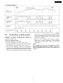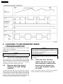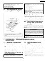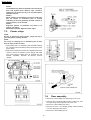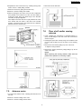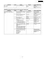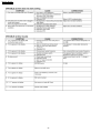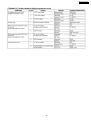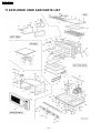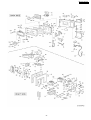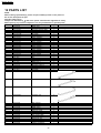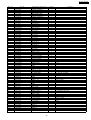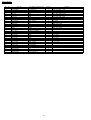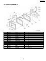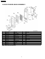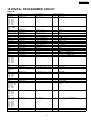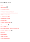
1
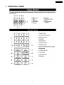
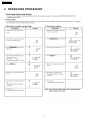
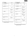
・CORDER NO. MOD0510275C2
Microwave Oven
NE-C1275
NE-C1475
© 2005 Matsushita Electric Industrial Co., Ltd. All
rights reserved. Unauthorized copying and
distribution is a violation of law.
NE-C1275 / NE-C1475
CONTENTS
Page
Page
1 CONTROL PANEL
3
10 TROUBLESHOOTING GUIDE
21
2 OPERATION PROCEDURE
4
11 EXPLODED VIEW AND PARTS LIST
26
3 SCHEMATIC DIAGRAM
9
12 PARTS LIST
28
4 WIRING DIAGRAM
10
13 DOOR ASSEMBLY
31
5 DESCRIPTION OF OPERATING SEQUENCE
11
14 ESCUTCHEON BASE ASSEMBLY
32
6 CAUTIONS TO BE OBSERVED WHEN TROUBLESHOOTING 14
15 PACKING AND ACCESSORIES
33
7 DISASSEMBLY AND PARTS REPLACEMENT PROCEDURE 15
16 WIRING MATERIAL
34
8 COMPONENT TEST PROCEDURE
18
17 DIGITAL PROGRAMMER CIRCUIT
35
9 MEASUREMENTS AND ADJUSTMENTS
20
18 DIGITAL PROGRAMMER CIRCUIT
37
2
NE-C1275 / NE-C1475
1 CONTROL PANEL
3
NE-C1275 / NE-C1475
2 OPERATION PROCEDURE
4
NE-C1275 / NE-C1475
5
NE-C1275 / NE-C1475
6
NE-C1275 / NE-C1475
7
NE-C1275 / NE-C1475
8
NE-C1275 / NE-C1475
3 SCHEMATIC DIAGRAM
9
NE-C1275 / NE-C1475
4 WIRING DIAGRAM
10
NE-C1275 / NE-C1475
5 DESCRIPTION OF OPERATING SEQUENCE
5.1.
Variable power cooking
control
output of the microwave oven is as shown in table.
NOTE 1:
The ON/OFF time ratio does not correspond with the
percentageof microwave power since approximately 2
seconds are required for heating of magnetron filament.
NOTE 2:
ON-OFF time of power relays are changed by digital
programmer circuit when remaining cooking time or
selected cooking time are within 1 minutes 30 seconds at
MED, LOW, SIMMER and Defrost cooking mode.
The coil of power relays are energized intermittently by the
digital programmer circuit, when the oven is set at any power
selection except for High power position. The digital
programmer circuit controls the ON-OFF time of power relays
contacts in order to vary the output power of the microwave
oven.
The relation between indictions on the control panel and the
11
NE-C1275 / NE-C1475
5.2.
power relays alternately again.
Convection cooking control
NOTE 1:
When convection is selected with temperature setting of
100-250°C, off period of both heaters is also programmed
while oven temperature is lower than selected
temperature, asshown in figure.
NOTE 2:
After convection process, if oven temperature is higher
than predetermind temperature, fan motor rotates for 5
minutes at maximum time to cool the electric components
and oven.
The digital programmer circuit controls the ON-OFF time of
upper and convection heater inorder to control the oven cavity
temperature, see table and figure.
1. The digital programmer circuit generatesthe power relays
control signals at a specific timing as shown in table.
2. When the oven reaches the selected temperature, the
digital programmer circuit senses the temperature through
oven temp sensor and stops supplying 12V DC to the
power relays resulting in turn off of uper and convection
heaters. After the heaters have been turned off, the oven
temperature will continue to increase a while then decrease
as shown in figure.
3. When the oven temperature drops below selected
temperature, the digital programmer circuit senses the oven
temperature and starts supplying 12V DC to the coils of
5.3.
predetermind temperature, fan motor rotates for 5 minutes
at maximum time to cool the electric components and
oven.
Grill cooking control
1. The digital programmer circuit generates the power relays
control signals at a specific timing as shown in figure.
2. When the oven temperature reaches the predetermined
temperature, the digital programmer circuit stops supplying
power relays control signas resulting in both upper to
turnoff.
3. When the oven temperature drops below the
predetermined temperature, the digital programmer circuit
generates power relays control signals again at the timing
predetrmined.
NOTE 1:
After grill process, if oven temperature is higher than
12
NE-C1275 / NE-C1475
5.4.
power relay 1, 3 contol signal so that microwave activity
continue at predetermined duty ratio as shown in figure.
The microwave activity continue to cycle until entire cooking
programme is completed.
Combination cooking control
Combination cooking is accomplished by operating the
microwave and heater mode alternately during one
combination cooking cycle.
There are 2 combination mode:
1. Grill combination (Grill + Microwave)
2. Convection combination (Convection + Microwave)
3. When the oven temperature drops below the selected
temperature, the digital programmer circuit generates
power relays contol signals again at the timing
predetermined.
1. The digital programmer circuit generates the power relays
control signals at a specific timing as shown in figure.
NOTE 1:
After combination process, if oven temperature is higher
than predetermind temperature, fan motor rotates for 5
minutes at maximum time to cool the electric components
and oven.
2. When the oven temperature reaches the predetermined
temperature, the digital programmer circuit stops supplying
power relays control signals resulting in heaters to turn off.
During this, digital programmer circuit continues supplying
13
NE-C1275 / NE-C1475
6 CAUTIONS TO BE OBSERVED WHEN
TROUBLESHOOTING
Unlike many other appliances, the microwave oven is a high
voltage, high current apparatus.
Although it is safe to operate, extreme care should be taken
during repair.
WARNING
There is high-voltage present, with high-current capabilities in the
circuits of the high voltage winding and filament winding of the high
voltage transformer. It is extremely dangerous to work on or near
these circuits with the oven energized.
DO NOT measure the voltage in the high voltage circuit including
filament voltage of magnetron.
CAUTION
Servicemen should remove their watches and rings whenever working
close to or replacing the magnetron.
6.1.
WARNING
Never touch any circuit wiring with your hand nor with an insulated tool
during operation.
Check the earthing/grounding
Do not operate on a 2 wire extension cord. The microwave
oven is designed to be used in a completely earthed/grounded
condition. It is imperative, therefore, to make sure it is properly
earthed/grounded before beginning repair work.
6.2.
6.3.
Warning about the electric
charge in the high voltage
capacitor.
If the door lock, the door
switch, the door seal or the
door develops a malfunction,
be sure not to operate the
oven until complete repairs
are made.
If the oven is operated with any of these parts in imperfect
condition, hazardous microwave leakage might occur.
For about 30 seconds after the oven is turned off, an electric
charge remains in the high voltage capacitor. When replacing
or checking parts, remove the power plug from the outlet and
short the terminal of the high voltage capacitor (terminal of lead
wire from diode) to chassis ground with and insulated handle
screwdriver or insulated jumper lead wire to discharge.
14
NE-C1275 / NE-C1475
WARNING
Never operate the oven until the following are confirmed:
(A) The door is tightly closed.
(B) There is no broken hinge or door arm.
(C) The door seal is not damagd.
(D) The door is not bent or warped.
(E) There is no other visible damage.
6.4.
Important Note
1. High voltage (above 250 volts) exists at following parts during
oven operation.
· Magnetron
· High Voltage Transformer
· High Voltage Diode
· High Voltage Capacitor
When parts must be replaced,
remove the power plug from
the outlet.
2. If the microwave oven is operated with incorrect installed door
hinge or magnetron, it can cause microwave leakage of over
5mW/square centimeter.
Hence it is absolutely necessary to check if magnetron and door
hinge are correctly and safety installed after repairs or
replacement.
6.5.
Confirm after repair
1. After repair or replacement of parts, make sure that the
screws of the oven, etc. are neither loose nor missing.
Microwave might leak if screws are not properly tightened.
2. Make sure that all electrical connections are tight before
inserting the plug into the wall outlet.
6.6.
Avoid inserting nails, wire, etc.
through holes in unit during
operation.
Never insert a wire, nail or any other metal object through the
lamp holes on the cavity or any other holes or gaps, because
such objects may work as an antenna and cause microwave
leakage.
CAUTION
MICROWAVE RADIATION
Personnel should not be exposed to the microwave energy which may
radiate from the magnetron or other microwave generating device if it
is improperly used or connected. All input and output microwave
connections waveguides, flanges, and gasket must be secure. Never
operate the device without a microwave energy absorbing load
attached. Never look into an open waveguide or antenna while the
device is energized.
CAUTION
High voltage parts may become uncovered when outer cabinet is
removed.
7 DISASSEMBLY AND PARTS REPLACEMENT
PROCEDURE
7.1.
Magnetron (Front and Back)
7.2.
1. Discharge the high voltage capacitors.
2. Remove 5 screws holding air guides.
Digital programmer circuit
(DPC)
1. Remove 1 screw holding grounding strip tab of membrane
switch.
3. Disconnect magnetron, lead wire connectors and grounding
lead.
4. Loosen wire harness and lift up air guide.
2. Remove 2 screws holding escutcheon base and slide the
escutcheon base upward slightly with door opened.
5. Remove 4 screws holding each magnetron.
3. Disconnect all connectors from DPC.
6. Remove 2 screws holding thermal cutout.
4. Remove 3 screws holding DPC.
NOTE:
To prevent microwave leakage, tighten mounting
screws making sure there is no gap between the
waveguide and the magnetron.
To replace membrane key board
1. Bend escutcheon A catch hooks straighten and separate
escutcheon A and base.
2. Push the upper part of key board (display window) from
back of escutcheon base and peel off membrane key
board.
CAUTION
When replacing the magnetron, be sure the antenna gasket is in
place.
15
NE-C1275 / NE-C1475
NOTE 1:
The membrane key board is attached to the escutcheon
base with double faced adhesive tape. Therefore,
applying hot air from A hair dryer is recommended for
smoother removal.
NOTE 2:
When installing new membrane key board, make sure
that the surface of escutcheon base is cleaned
sufficiently so that any problems (shorted contacts or
uneven surface) can be avoided.
NOTE 3:
Alignment position of membrane key board is as
follows (see figure);
Membrane key board: Right and lower edges
7.3.
Power relays
NOTE:
Be sure to ground any static electric charge built up on
your body before handling the DPC.
NOTE:
Do not use a soldering iron or desoldering tool of more
than 30 watts on DPC contacts.
1. Using solder wick or a desoldering tool and 30W soldering
iron, carefully remove all solder from the terminal pins of the
power relays.
2. With all the terminal pins cleaned and separated from DPC
contacts, remove the defective power relay(s) and install
new power relay(s) making sure all terminal pins are
inserted completely. Resolder all terminal contacts
carefully.
7.4.
Door assembly
1. Remove 2 screws holding the upper hinge to the oven.
2. Open the door and while pulling the door toward you, work
the upper hinge out through the hole in the oven.
3. Remove 4 screws holding the door C.
4. Remove the door C by carefully pulling outward starting
from the upper right hand corner.
5. Remove 2 screws holding door E.
16
NE-C1275 / NE-C1475
4. Disconnect motor lead wire.
6. Separate the door A from door E by carefully freeing catch
hooks on door A while pulling outward.
7. Remove the door key spring and the door key.
8. Remove 2 screws holding door handle.
9. When mounting the door to the oven, be sure to adjust the
door parallel to the bottom line of the oven face plate by
moving the upper hinge and lower hinge in the direction
necessary for proper alignment.
Also adjust so that the door has no play between the inner
door surface and oven frame. If the door is not mounted
properly, microwave energy may leak from the clearance
between the door and the oven.
7.6.
Floor shelf and/or moving
antenna
1. Insert a philips type screwdriver or equivalent approx. 2”
(5cm) in shaft length in the hole of left side oven wall as
shown in Figure.
2. Carefully lift up the floor shelf by using the screwdriver until
the floor shelf is lifted up over the level of oven opening
front.
3. Remove the floor shelf by lifting it up from oven front.
To replace moving antenna.
4. Remove the moving antenna by simply lifting it up off the
stirrer motor shaft.
NOTE:
When replacing the moving antenna, make sure the
plastic stirrer spacers are correctly in place.
7.5.
Antenna motor
1. To remove the antenna motor, carefully place the unit on its
left side.
2. Remove 2 screws holding motor cover.
3. Remove 2 screws holding antenna motor.
17
NE-C1275 / NE-C1475
7.7.
Convection Heater
1. Remove 10 screws holding back panel.
2. Disconnect heater and circulation fan motor lead wire
connector.
3. Remove a screw holding exhaust guide.
4. Remove 5 screws holding heater panel.
5. Slide up heater panel unit to release from oven cavity.
6. Remove 6 screws holding heater support and heater.
NOTE:
After oven has been used the internal surface of the
cavity may become permanently dark.
Please note this condition is normal and it does not
affect ovens performance.
7.8.
Upper Heater
1. Disconnect upper heater lead wire connector.
2. Remove 1 screw holding heater support.
3. Remove the heater by pulling it out.
8 COMPONENT TEST PROCEDURE
2. Normal (cold) resistance readings should be as follows:
Secondary winding - Approx. 80Ω ~ 120Ω
Filament winding - Approx. 0Ω
Primary winding (0V - 240V). Approx. 0Ω ~ 3Ω
CAUTION
1. High voltage is present at the high voltage terminal of the high
voltage transformer during any cook cycle.
2. It is neither necessary nor advisable to attempt measurement of
the high voltage.
3. Before touching any oven components, or wiring, always unplug
the oven from its power source and discharge the high voltage
capacitor.
8.1.
High voltage transformer
1. Remove connections from the transformer terminals and
check continuity.
18
NE-C1275 / NE-C1475
8.2.
High voltage capacitor
8.4.
1. Check continuity of capacitor with ohmmeter on highest
OHM scale.
Magnetron
Continuity checks can only indicate an open filament or a
shorted magnetron. To diagnose for an open filament or
shorted magnetron.
2. A normal capacitor will show continuity for a short time, and
then indicate 9MΩ once the capacitor is charged.
3. A shorted capacitor will show continuous continuity.
1. Isolate magnetron from the circuit by disconnecting the
leads.
4. An open capacitor will show constant 9MΩ.
(Due to internal 9MΩ resistor)
2. A continuity check across magnetron filament terminals
should indicate one ohm or less.
5. Resistance between each terminal and chassis should be
infinite.
3. A continuity check between each filament terminal and
magnetron case should read open.
8.3.
Diode
8.5.
1. Isolate the diode assembly from the circuit by disconnecting
the leads.
Membrane key board
(Membrane switch assembly)
Check continuity between switch terminals, by pressing an
appropriate pad on the key board.
The contacts assignment of the respective pads on the key
board is as shown in the schematic diagram of DPC.
2. With the ohmmeter set on the highest resistance scale,
measure the resistance across the diode terminals.
Reverse the meter leads and again observe the resistance
reading. A meter with 6V, 9V or higher voltage batteries
should be used to check the front-to-back resistance of the
diode, otherwise infinite resistance may be read in both
directions.
A normal diode’s resistance will be infinite in one direction
and several hundred KΩ in the other direction.
19
NE-C1275 / NE-C1475
8.6.
Protector diode
8.7.
1. Isolate the protector diode assembly from the circuit by
disconnecting its leads.
To test the oven temp sensor
thermistor
This sensor monitors the heat produced by the heater circuit
and maintains the oven temperature the user has selected.
Normal room temperature, especially in a kitchen can vary
anywhere from 10°C to 32°C. The reading across the oven
sensor thermistor should be within 100K ohm to 500K ohm
when reading in an area within the 10°C to 32°C room
temperature range.
If the resistance reading is out of the range stated here, the
sensor is defective and must be replaced with sensor unit.
2. With the ohmmeter set on the highest resistance scale,
measure the resistance across the protector diode
terminals.
Reverse the meter leads and again observe the resistance
reading.
A normal protector diode’s resistance will be infinite in both
directions.
It is faulty if it shows continuity in one or both directions.
NOTE 1:
When measuring resistance disconnect the 4-pin
connector (CN4) from the DPC otherwise a false reading
may be indicated.
NOTE 2:
If checking an oven sensor thermistor just after the
microwave oven has been operating, the sensor of course
won’t be room temperature. In this case the sensor must
be removed and allowed to cool down to the 50°F/10°C to
90°F/32°C range.
9 MEASUREMENTS AND ADJUSTMENTS
9.1.
Adjustment of Primary latch
switch, Secondary latch
switch and short switch
heating time, should be as accurate as possible.
Output power performance test procedure.
1. Fill the beaker with exactly one litre of tap water.
Stir the water using the thermometer and note the
temperature. (Record as T1)
1. When mounting Primary latch switch, Secondary latch
switch and short switch to door hook assembly, mount the
Primary latch switch, the Secondary latch switch and the
short switch to the door hook assembly as shown in Figure.
2. Place the beaker in the center of cook plate.
Set the oven for High power and heat for exactly one
minute.
3. After completion of the heating cycle, stir the water again
with the thermometer and note the temperature. (Record as
T2).
2. When mounting the door hook assembly to the oven
assembly, adjust the door hook assembly by moving it in
the direction of arrow in Figure so that the oven door will not
have any play in it. Check for play in the door by pulling the
door assembly. Make sure that the latch keys move
smoothly after adjustment is completed. Completely tighten
the screws holding the door hook assembly to the oven
assembly.
9.2.
The normal temperature rise (T2-T1), for these models should
be more than following chart indicated using the High power
selection with the oven operating at the specified line voltage.
Measurement of microwave
output
The output power of the magnetron can be determined by
performing IEC standard test procedures. However, it is
possible to test the magnetron by following procedure outlined
below.
Necessary equipment:
1 litre beaker
Glass thermometer
Wrist watch or stopwatch
NOTE:
Check the line voltage under load to ensure it meets
specifications. Low voltage condition will cause a
reduction in magnetron output. Temperature readings and
20
NE-C1275 / NE-C1475
TABLE (1 litre-1min. test)
RATED OUTPUT
1100W (IEC-705)
1300W (IEC-705)
TEMPERATURE RISE
Min 9.4°C
Min 11.1°C
10 TROUBLESHOOTING GUIDE
CAUTION
1. Check grounding before checking for trouble.
2. Be careful of the high voltage circuit.
3. Discharge high voltage capacitor.
4. When checking the continuity of the switches or the high voltage transformer, disconnect one lead wire from these parts and then check
continuity with the AC plug removed. To do otherwise may result in a false reading or damage to your meter.
5. Do not touch any parts of the circuitry on the digital programmer circuit, since static electric discharge may damage this control panel.
Always touch yourself to ground while working on this panel to discharge any static charge in your body.
6. A 230/240V AC is present at the shaded area of the digital programmer circuit (Terminals of power relays and switching power supply circuit).
When troubleshooting, be cautious of possible electrical shock hazard.
First of all operate the microwave oven following the correct operating procedures described in order to find the exact cause of any
trouble.
21
NE-C1275 / NE-C1475
22
NE-C1275 / NE-C1475
23
NE-C1275 / NE-C1475
24
NE-C1275 / NE-C1475
25
NE-C1275 / NE-C1475
11 EXPLODED VIEW AND PARTS LIST
26
NE-C1275 / NE-C1475
27
NE-C1275 / NE-C1475
12 PARTS LIST
NOTE:
When ordering replacement(s), please use part number(s) shown in this parts list.
Do not use description the part.
Important safety notice:
mark have special characteristics important for safety.
Components identified by
When replacing any of these components, use only manufacturer’s specified parts.
Ref. No.
Part No.
1
A100D3840AP
2
A00064080BP
3
ANE0072L20AP
3
ANE0072Z70GP
4
A010T3C50BP
5
ANE02396000BP
6
A400B3840AP
7
ANE0911000CC
8
ANE0911000DF
9
ANE0928000AS
10
ANE000Z000AA
11
ANE000Z000AD
12
ANE0922000EF
13
ANE0922000EH
14
ANE0922000FJ
15
ANE0922000JQ
16
ANE000Z000AB
17
ANE0924000AJ
18
ANE0926000CE
19
ANE0927000BK
20
A100A-3B40
21
A100L3230BP
22
A100Q3230BP
23
A1007-3280
24
A1008-3280
25
A10263030GP
26
ANE10288U0AP
27
A10473230BP
28
A1183-3810
29
A18073C50BP
Part Name & Description
CABINET BODY
CAUTION LABEL
OVEN LAMP CAUTION LABEL
OVEN LAMP CAUTION LABEL
SHELF
CORD LABEL
FILTOR
CUSHION RUBBER B
CUSHION RUBBER B
CUSHION RUBBER B
CUSHION RUBBER C
CUSHION RUBBER C
CUSHION RUBBER C
CUSHION RUBBER C
CUSHION RUBBER C
CUSHION RUBBER C
CUSHION RUBBER C
CUSHION RUBBER C
CUSHION RUBBER
CUSHION RUBBER
BASE
BACK PANEL COVER
BACK PANEL
RUBBER FOOT A
RUBBER FOOT
OVEN LAMP COVER (U)
ANTENNA MOTOR COVER
LOWER SASH
BACK PANEL
RAIL(RIGHT) NEW
29
A33013C50BPS
RAIL(RIGHT) OLD
2
30
A18083C50BP
RAIL(LEFT) NEW
2
30
A33023C50BPS
RAIL(LEFT) OLD
2
31
32
33
34
35
36
37
38
39
40
41
42
43
44
A18593C50BP
A200A3C50BP
A20194210AQ
A202J3230BP
A202K3230BP
A202L3881BP
A203M3230BP
A20853230BP
A22363230BP
A22373230BP
A22392020AP
A22413230BP
A22423230BP
A22433230BP
SHELF SUPPORT
OVEN CAVITY
ANTENNA STOPPER
ANTENNA SHAFT
ANTENNA (U)
REFLECTION PLATE
CIRCULATION FAN CASE
DOOR HOOK MOUNTING A
RIGHT HEATER PANEL
LEFT HEATER PANEL
CIRCULATION FAN
BACK HEATER PANEL
ADIABATIC MATERIAL A
ADIABATIC MATERIALB
4
1
4
1
1
4
1
1
1
1
1
1
1
1
28
Pcs/set
1
1
1
1
1
1
2
2
2
1
7
1
1
1
1
1
8
1
2
1
1
1
1
4
4
1
1
1
1
2
Remarks
NE-C1275BPQ
NE-C1275 / NE-C1475
Ref. No.
Part No.
45
A22583230BP
46
A22593230BP
47
A22603230BP
48
A22613230BP
49
A22773230BP
50
A22783230BP
51
A23793230BP
52
A23853230BP
53
A301L3230BP
54
A30203230GP
55
A3136-3470
56
A3137-3850
57
A3138-3470
58
ANE32398U0AP
59
ANE32628U0AP
60
A400A3230BP
61
A400E3230BP
62
A400K3230BP
63
A400T3230BP
64
A402A3230BP
65
A40213230BP
66
A40313230BP
67
A41573230BP
68
A41592020AP
69
A41613230BP
70
A41622020AP
71
A41632020AP
72
A41793230BP
73
A41806000BP
74
A42123230BP
75
A42563230BP
76
A441Y3230BP
77
XTWANE3+10EX
78
ANE6030Q50GN
79
A60373230BP
80
A605S3030GP
81
A605Y3880BP
82
A610A3230BP
83
A61413230BP
84
ANE61448V0AP
85
A61455850GP
86
A61523230BP
87
A61983230BP
88
A620X3230BP
89
A6202-3X2
90
J621B3C50BP
90
J621B3C60EU
91
A62193230BP
92
ANE6230P10GN
93
A62383230GP
94
A630G3C50BP
94
A630G3C60EU
96
A63023230BP
97
A631U3C50BP
98
A6408-2050
99
A64173230BP
100
A6437-1600
101
A64643230BP
102
A65533230BP
103
A6145-1E30
104
A65953170GP
105
A05423230BP
106
A692Y3C60EU
107
A901A3230BP
107
A901A3230GP
108
XWNANE65GV
109
A31454740AP
110
ANE9080-730
111
ANE9107A20GN
112
A97213230BP
113
A97223230BP
114
A97233230BP
115
A98243230BP
116
AESMTG35C60
Part Name & Description
ADIABATIC MATERIAL C
ADIABATIC MATERIAL D
ADIABATIC MATERIAL E
ADIABATIC MATERIAL F
LOWER HEATER PANEL
UPPER HEATER PANEL
ADIABATIC MATERIAL G
ADIABATIC MATERIAL H
HINGE
DOOR HOOK
HOOK SPACER A
HOOK SPACER B
HOOK SPACERC
LEVER SPRING A
LEVER SPRING B
FAN MOTOR
AIR GUIDE A
EXHAUST GUIDE
AIR GUIDE D
AIR GUIDE E
FAN CASE COVER
AIR GUIDE C
FAN BRACKET A
FAN
FAN SPACER A
FAN SPACER B
FAN SPACER C
HEATER FAN MOTOR
HEATER FAN MOTOR BRACKET
AIR GUIDE I
AIR GUIDE J
EXHAUST COVER
SCREW
INCANDESCENT LAMP
CAPACITOR BRACKET
PC BOARD H (U)
OVEN TEMP SENSOR
SAFETY SWITCH A
LATCH SWITCH A
ANTENNA MOTOR
THERMAL CUTOUT
SOCKET
MOTOR BRACKET
CHANGE-OVER SWITCH
DIODE.SI, 0.35A
H.V.TRANSFORMER
H.V.TRANSFORMER
INSULATION COVER
FUSE
SPACER
HEATER A (U)
HEATER A (U)
INSULATION COVER B
HEATER E
WASHER
HEATER SUPPORT A
GLASS PLATE
HEATER SUPPORT B
HEATER BRACKET
THERMAL CUTOUT B
FUSE B
CAUTION LABEL
NOISE FILTER
AC CORD W/PLDG
AC CORD W/PLDG
SPACER
DOOR SCREEN A
CLIP
CORD HOLDER
BRACKET A
BRACKET B
BRACKET C
GLASS PLATE BRACKET
TRIAC
29
Pcs/set
1
1
1
1
1
1
1
2
1
1
1
1
1
1
3
1
1
1
1
1
1
1
1
1
1
1
1
1
1
1
1
2
4
1
2
1
1
1
1
1
2
1
1
1
2
2
2
1
1
3
4
4
2
2
1
2
1
2
2
1
1
1
1
1
1
1
1
1
1
1
1
1
Remarks
(85W)
34W
3×10 THERMISTOR
(V-16G-3E6)
(V-15G-3C26)
(3W)
FOR MAGNETRON
(V-15G-1E5-M)
1.4kVA NE-C1275BPQ
1.4kVA NE-C1475EUG
16A
NE-C1275BPQ
NE-C1475EUG
for HVT
CIRCULATION FAN CASE
1.25A
NE-C1275 BPQ
NE-C1475 EUG
NE-C1457 EUG
CABINET
(YELLOW)
600V 30A
NE-C1275 / NE-C1475
Ref. No.
Part No.
117
MS212854KW91
117
MS212105KW91
118
XNG4EVSL
119
XNW5EFN
120
XST4+6VS
121
XTC4+10BC
122
XTC4+10FC
123
XTEA5+E10FJ
124
XTTANE4+B10S
125
XTT4+12BVKJ
126
XTWANE4+10RUJ
127
XUEANE32KP
128
XWA4BV
129
XWC4BPN
130
XWG4BV
131
XTEANE3+6BJ
132
A2387-3810
133
XYCA4+EE8J
134
XYC4+F16XN
135
XYD4+EE12FJ
136
XYE6+F20FJ
137
XYN4+J10FN
138
2M167B-M14J1
139
A41636000BP
140
A66623170GP
141
XSWA5+10UJ
142
A20343840AP
143
A62443230BP
144
ANE092E000BK
145
ANE90828U0AP
146
A40923030GP
147
ANE42408U0AP
Part Name & Description
H.V.CAPACITOR
H.V.CAPACITOR
NUT, COUNTER CLOCKWISE
NUT
SCREW
SCREW
SCREW
SCREW
SCREW
SCREW (BLACK)
SCREW
RING
WASHER
WASHER
WASHER
SCREW
ADIABATIC MATERIAL J
SCREW
SCREW
SCREW
SCREW
SCREW
MAGNETRON
FAN SPACER C
EARTH SPACER
SCREW
OVEN BRACKET
HEAT SINK
CUSHION RUBBER
CLIP
FILTOR HANDLE
FILTOR HANDLE B
30
Pcs/set
2
2
1
5
1
6
1
4
4
6
8
1
1
1
1
4
1
6
4
2
1
2
2
1
1
4
1
1
1
2
2
2
Remarks
NE-C1275 BPQ 0.85MF
NE-C1475 EUG 1.0MF
HEATER FAN MOTOR M4 SUS
SHELF SUPPORT SPACER
(4×6) LAMP GLASS PLATE
(4×10)CABINET BODY
(4×10)OVEN LAMP COVER
(5×10)H.V.TRANSFORMER
(4×10)CIRCULATIOH FAN CASE
(4×12)BASE
(4×10)MAGNETRON
HEATER FAN MOTOR
HEATER FAN MOTOR
OVEN LAMP COVER
HEATER FAN MOTOR
3×6 THERMAL CUTOUT
(4×8) CAPACITOR BRACKET FAN MOTOR DIODE WASHER
(4×16)HEATER SUPPORT
(4×12)EARTH
(6×20)EARTH
(4×10)TRIAC
NE-C1475 EUG
(5×10)HINGE
NE-C1275 / NE-C1475
13 DOOR ASSEMBLY
Ref. No.
Part No.
D1
A300A3230BP
D2
A300B3230BP
D3
A30013C50BP
D4
A301H-3850
D5
A302K3230BP
D6
A30183230BP
D7
A30193230BP
D8
ANE30218U0AP
D9
ANE30562Q0AP
D10
ANE3070P60AP
D11
A30853C50BP
D12
ANE3134P60AP
D13
A31463230BP
D14
A31473230BP
D15
XYN4+J30FN
D16
A32133230BP
D17
A32163230BP
D18
XTBANE4+12FKJ
D19
XYN4+F25FN
D20
A33343C50BP
D21
A31863C50BP
D21
A31863C60EU
Part Name & Description
DOOR B
UPPER HINGE
DOOR A (U)
DOOR KEY LEVER B
DOOR E (U)
DOOR KEY A
DOOR KEY B
DOOR KEY SPRING
HANDLE PIN
HANDLE PEICE A
DOOR C
HANDLE PIECE B
DOOR SCREEN B (U)
HANDLE PIECE C
SCREW
DOOR HANDLE SPACER
HANDLE SPACER
SCREW
SCREW
DOOR GASKET RUBBER
DOOR PANEL
DOOR PANEL
31
Pcs/Set
1
1
1
1
1
1
1
1
2
1
1
1
1
1
2
2
2
4
2
1
1
1
Remarks
W/DOOR SCREEN A
4×30
4×12 BLACK
4×25
NE-C1275 BPQ
NE-C1475 EUG
NE-C1275 / NE-C1475
14 ESCUTCHEON BASE ASSEMBLY
Ref. No.
Part No.
E1
A01573C50BP
E1
A01573C60EU
E2
ANE0962000AH
E3
A603L3C50BP
E3
A603L3C50EU
E4
A605Q3C50BP
E5
RP-SD016BCS0
E6
A83373C50BP
E7
XTW3+10BJ
E8
A64793C50BP
E9
A4898-3B40
E10
A800N-3B40
E11
A80343C50BP
E12
ANE0962000DE
E13
A80023C50BP
E14
A8032-3B40
E15
A8265-3B40
E16
A6408-3280
Part Name & Description
NAME LABEL
NAME LABEL
CUSHION RUBBER D
D.P.CIRCUIT (U)
D.P.CIRCUIT (U)
PC BOARD F (U)
SD MEMORY CARD
ESCUTCHEON SHEET
SCREW
MEMBRANE SWITCH
SCREW
ESCUTCHEON A
ESCUTCHEON BASE
CUSHION RUBBER D
ESCUTCHEON B
SD BRACKET
PUSH LOCK
WASHER
NOTE 1: Please order name label together.
32
Pcs/Set
1
1
2
1
1
1
1
1
8
1
1
1
1
1
1
1
1
1
Remarks
NE-C1275BPQ
NE-C1475EUG
NE-1275 BPQ RTL(W/COMPONENT)
NE-1475 EUG RTL(W/COMPONENT)
SD CARD SLOT
W/MEMORY WROTE
3×8
SD SLOT COVER
NOTE 1
SD SLOT COVER
NE-C1275 / NE-C1475
15 PACKING AND ACCESSORIES
Ref. No.
Part No.
P1
A00033C50BP
P1
A00033C60EU
P2
A01023C50BP
P2
A01023C60EU
P3
A01043840AP
P4
A01053840AP
P5
A01065130AP
P6
ANE0107580AP
P7
A01083C50BP
P8
A01173230BP
P9
A01453230BP
P10
A01173C50BP
P11
A04243C60EU
P12
A04203C50BP
P12
A04203C60EU
P13
A06023C50BPS
P14
A06033230GP
P15
A02843560BP
P16
A400B3840AP
P17
XYN4+C10V
P18
A06433C50BP
P19
ANE01072Q10AP
P20
XNG4V
Part Name & Description
INSTRUCTION BOOK
INSTRUCTION BOOK
PACKING CASE, PAPER
PACKING CASE, PAPER
UPPER FILLER
LOWER FILLER
VINYL COVER
DOOR SHEET
TRAY PACKING A
TRAY PACKING B
DOOR SHEET B
TRAY PACKING B
INSTRUCTION BOOK B
OPERATING GUIDE
OPERATING GUIDE
WIRE RACK SHELF (U)
CERAMIC INSULATING TRAY
NUMBER LABEL
FILTOR
SCREW
WIRE RACK FOOT
DOOR SHEET
NUT
33
Pcs/Set
1
1
1
1
1
1
1
1
1
1
1
1
1
1
1
1
1
1
2
4
8
1
4
Remarks
NE-C1275BPQ
NE-C1475EUG
NE-C1275BPQ
NE-C1475EUG
NE-C1475EUG
NE-C1275BPQ
NE-C1475EUG
FOR WIRE RACK 4×10 STAINLESS
M4 STAINLESS
NE-C1275 / NE-C1475
16 WIRING MATERIAL
Ref. No.
Part No.
W1
A030A3C50BP
W2
A03603C50BP
W3
A61393230BP
W4
A50966520UP
W5
A606V3230BP
W6
A606W3230BP
Part Name & Description
LEAD WIRE HARNESS
LEAD WIRE
INSULATION TUBE
FERRITE CORE
PROTECTOR DIODE A
PROTECTOR DIODE B
Pcs/Set
1
1
1
2
1
1
Remarks
Ref. No.
Part No.
Part Name & Description
REF.N0.80 P.C.BOARD H BUZZER PCB A605S3030GP
BZ
EFBRL37C20
BUZZER
CN551
K1KA03B00171
CONNECTOR
D551
MA2C19600E
DIODE.SI, 0.1A
Q551
2SD06390Q
TRANSISTOR, SI, 0.6W
R551
ERDS2TJ681T
CARBON FILM RESISTOR
R552
ERDS2TJ184T
CARBON FILM RESISTOR
R553
ERDS2TJ103T
CARBON FILM RESISTOR
REF.NO.106 NOISE FILTOR (U) A692Y3C60EU
C1
ECQU2A105MLA
POLYESTER CAPACITOR
C2, 3
ECQU2A472MLA
POLYESTER CAPACITOR
C4
ECQU2A684MLA
POLYESTER CAPACITOR
CN1
K1KA03A00299
CONNECTOR
F2
A62316000GP
FUSE HOLDER
F1
A62316010BP
FUSE HOLDER
L1
G0B901N00002
FILTOR COIL
R1
ERF15ZXJ240
RESISTOR
ZNR1
ERZV10D511CS
VARISTOR
ZNR2.3
ERZV10D112C1
VARISTOR
R2
ERDS1FJ244P
RESISTOR
Pcs/Set
Remarks
34
1
1
1
1
1
1
1
3.7KHZ
3 PIN RED AEEMMB00703R
MA196-(TA5)
2SD639-PQRS
680Ω, 1/4W 5%
180KΩ, 1/4W 5%
10KΩ, 1/4W 5%
1
2
1
1
2
2
1
1
1
2
1
l.0MF 250V
0.0047MF 250V
0.68MF 250V
3 PIN AEEMMD00703W
A621A-1810
24Ω, 15W, 5%
240KΩ, 1/2W, 5%
NE-C1275 / NE-C1475
17 DIGITAL PROGRAMMER CIRCUIT
SCHEMATIC DIAGRAM
35
NE-C1275 / NE-C1475
36
NE-C1275 / NE-C1475
18 DIGITAL PROGRAMMER CIRCUIT
PARTS LIST
Ref. No.
DISP110
D27, D220,
D222, D223,
D224, D225,
D226, D227,
D229, D230,
D231, D232,
D233, D311,
D312, D313
ZD10, ZD220,
ZD221, ZD222,
ZD223
D28
D26, D310
D40, D41, D42,
D43, D44, D45
R24, R26
R311
R316
R228, R229
R180, R181
Q313
C12
C26
C10
CX320
R28, R29
R25
CN6
CN5
CN3
Q180, Q213,
Q220, Q222,
Q223, Q224,
Q225, Q226,
Q227, Q228,
Q229, Q230,
Q231, Q232,
Q233
Q211, Q311
Q314
Q214, Q215,
Q212, Q310,
Q440
Q312
D180, D181,
D182, D183,
D184, D185,
D186, D187
IC10
IC310
IC380
R40, R41, R42,
R43, R44, R45,
R46, R47, R48,
R49, R398,
R399, R400,
R401, R402,
R403
R55, R111,
R112, R113,
R213, R214,
R220, R224,
R226, R251,
R319
R183, R216,
R221, R225,
R227, R234,
R236, R238,
R240, R242,
R244, R246,
R248, R250,
R252, R312,
R314, R317
R310, R318
R215
Part No.
A66173C50BP
B0AACK000004
Description
Display holder
Diode, Si 0.1A
Pcs/Set
1
16
B0BA01000049
Zenner Diode
5
MTZJ11BT77
B0EAEV000001
B0EAKR000018
B0JAAE000001
Diode Si, 0.5A
Diode Si, 1A
Diode, Si, 0.1A
1
2
6
ERA2210
ERA1506
RB721Q
ERDS1FJ563T
ERDS2TJ104T
ERDS2TJ122T
ERDS2TJ331T
ERDS2TJ471T
B1ACGF000004
ECEA1CKA220B
ECKN3A222KBP
EEUFC1C471B
EF0EC8004T4
ERG1SJ393E
ERX12SJ1R0E
K1KA03A00387
K1KA03AA0086
K1KA05A00237
B1ABCF000010
Carbon Film Resistor
Carbon Film Resistor
Carbon Film Resistor
Carbon Film Resistor
Carbon Film Resistor
Transistor, Si, 0.6W
Electric Capacitor, Al
Ceramic Capacitor
Electric Capacitor, Al
Resonator
Metal Oxcide Resistor
Metal Oxcide Resistor
Connector
Connector
Connector
Chip Transistor, Si, 0.2W
2
1
1
2
2
1
1
1
1
1
2
1
1
1
1
15
B1ADCF000001
B1CBGD000001
B1GBCFGN0001
Chip Transistor, Si, 0.2W
Chip Transistor, Si, 0.2W
Chip Transistor, Si, 0.3W
2
1
5
2SA1037AKT
2SK3018T106
AESC43ZKE
B1GDCFJJ0002
B3ABB0000239
Chip Transistor, Si, 0.3W
Chip LED
1
8
AESA14EKE
TLGV1022(T14MAT5, F)
C0CBCBD00043
C0EBE0000447
C3EBDC000063
D0GB101JA002
IC
IC
IC
Chip Resistor
1
1
1
16
PQ1L333M2SPQ
BD4928G, AEICBD4928G
BR24L02F-WE2
100Ω, 1/16W, 5%, AERJ3GSYJ101
D0GB102JA002
Chip Resistor
11
1K, 1/16W, 5%, AERJ3GSYJ102
D0GB103JA002
Chip Resistor
18
10K, 1/16W, 5%, AERJ3GSYJ103
D0GB104JA002
D0GB153JA002
Chip Resistor
Chip Resistor
2
1
37
Remarks
AESS133T-77
56K, 1/2W, 5%
100KΩ, 1/4W, 5%
1.2KΩ, 1/4W, 5%
330Ω, 1/4W, 5%
470Ω, 1/4W, 5%
KTA200-Y-AT/P
22MF/16V
0.0022MF/1KV
470MF/16V/FC
8000A
39KΩ, 1W, 5%
1Ω, 1/2W, 5%
Red 3 pin, AEEMMF00703R
White 3 pin, B03B-XASS-1-T(LF)(SN)
White 5 pin, AEEMMF01F05W
2SC2412KT146
100KΩ, 1/16W, 5%, AERJ3GSYJ104
15K, 1/16W, 5%, AERJ3GSYJ153
NE-C1275 / NE-C1475
R10, R182,
R313, R381
R27
R211, R233,
R235, R237,
R239, R241,
R243, R245,
R247, R249
R315
R110, R380
R212
R440
R441
C15, C16, C316,
C317, C398
C14, C27, C313,
C314, C319,
C380, C440
C40, C41, C42,
C43, C44, C381,
C382
C110, C111,
C112, C211,
C312, C318
IC1
DISP110
D10
IC26, IC27
IC230
C25
C230
R230
R231
R232
T25
CN1
CN2
CN11
CN7
CN9
RY9, RY10,
RY11, RY12
RY1, RY2, RY3,
RY4
RY5, RY6, RY7,
RY8
DISP110
IC25
D0GB222JA002
Chip Resistor
4
2.2K, 1/16W, 5%, AERJ3GSYJ222
D0GB223JA002
D0GB272JA002
Chip Resistor
Chip Resistor
1
10
22K, 1/16, 5%, AERJ3GSYJ223
2.7KΩ, 1/16W5%, AERJ3GSYJ272
D0GB333JA002
D0GB472JA002
D0GB751JA002
D1BB2201A001
D1BB8202A001
F1H1A105A019
Chip
Chip
Chip
Chip
Chip
Chip
Resistor
Resistor
Resistor
Resistor
Resistor
Capacitor
1
2
1
1
1
5
33K, 1/16W, 5%, AERJ3GSYJ333
4.7K, 1/16W, 5%, AERJ3GSYJ472
750Ω, 1/16W, 5%, AERJ3GSYJ751
2.2KΩ, 1/16W, 1%, AERJ3EKF2201
82KΩ, 1/16W1%, AERJ3EKF8202
1MF/10V, AECU1F105Z10
F1H1E104A030
Chip Capacitor
7
0.1MF/25V, AECU1F104Z25
F1H1H1010005
Chip Capacitor
7
0.0001MF/50V, AECU1C101J50
F1H1H103A220
Chip Capacitor
6
0.01MF/50V, AECU1F103Z50
MN101C66GDB1
A67523C50BP
B0JAMK000017
B3PAA0000387
B3PAC0000128
ECA2WHG220E
ECQU2A104MNA
ERG1SJ101P
ERQ12AJ201P
ERQ14AJ331P
ETS19AA2B1AC
K1KA03AA0134
K1KA03AA0135
K1KA05AA0134
K1KA08AA0201
K1MN10AA0040
K6B1AGA00119
LSI
Display sheet
Diode, Si, 1.5A
IC
Photo Coupler IC
Electric Capacitor, Al
MP Capacitor
Metal Oxcide Resistor
Fuse Resistor
Fuse Resistor
Switching Tranasformer
Connector
Connector
Connector
Connector
Connector
Relay
1
1
1
2
1
1
1
1
1
1
1
1
1
1
1
1
4
MEC/MN101C66G
K6B1AGA00140
Relay
4
G5G-1A
K6B1AGA00212
Relay
4
ALE73B12
L5AAAFD00029
MIP0255SPSCF
LCD Display
IC
1
1
CG2020-TTNC
MIP0255SPSCF
38
AESSRK19
AEICP25011HL
TLP665J(D4, S)
22MF/450V/105C
0.1MF, 250V
100Ω, 1W 5%
200Ω, 1/2W, 5%
330Ω, 1/4W, 5%
MACO
White 7(3) pin, B3(7.5)B-XASK-1-A(LF)(SN)
Red 7(3) pin, B3(7.5)B-XARK-1-A(LF)(SN)
White 13(5) pin, B5(7.5)B-XASK-1-A(LF)(SN)
White 8 pin, B08B-PASK-1(LF)(SN)
10FDZ-BT-M(S)(LF)(SN)
ALD112A04J
WP-596(F)
S-3C50BPQ
Printed in Japan