1
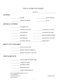
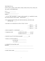
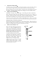
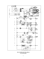
BOCK ENGINEERED PRODUCTS
OPERATION AND SERVICE MANUAL
FOR THE
FP-95
FOOD PROCESSING CENTRIFUGE
BEP
TEST & INSPECTION SHEET
SOLD TO _____________________________
MACHINE
_______________ MODEL
_______________ BOCK ORDER #
_______________ SERIAL NUMBER
_______________ DATE
MOTOR & CONTROLS
_______________ INVERTER S/N
_______________ MOTOR VOLTAGE
_______________ CONTROL VOLTAGE
_______________ MOTOR MFG
_______________ INCOMING POWER
_______________ MOTOR S/N
_______________MOTOR HORSEPOWER
_______________ MOTOR RPM
_______________ MOTOR PULLEY SIZE
_______________ MOTOR CODE NO.
_______________ DRIVE BELT
DRIVE UNIT AND BASKET
_______________ UNIT PULLEY SIZE
_______________ BASKET RPM (MAXIMUM)
_______________ BASKET WEIGHT CAPACITY
TESTING RESULTS
_______________ PROCEDURE NUMBER USED
_______________ STARTING AMPS
_______________ RUNNING AMPS
_______________ BRAKING TIME
_______________ INSPECTORS INITIALS
BOCK ENGINEERED PRODUCTS, INC
3600 SUMMIT ST.
TOLEDO, OHIO 43611
FORM Z-00860
REV B 3/30/99
2
TEST & INSPECTION SHEET
SOLD TO _____________________________
MACHINE
_______________ MODEL
_______________ BOCK ORDER #
_______________ SERIAL NUMBER
_______________ DATE
MOTOR & CONTROLS
_______________ INVERTER S/N
_______________ MOTOR VOLTAGE
_______________ CONTROL VOLTAGE
_______________ MOTOR MFG
_______________ INCOMING POWER
_______________ MOTOR S/N
_______________MOTOR HORSEPOWER
_______________ MOTOR RPM
_______________ MOTOR PULLEY SIZE
_______________ MOTOR CODE NO.
_______________ DRIVE BELT
DRIVE UNIT AND BASKET
_______________ UNIT PULLEY SIZE
_______________ BASKET RPM (MAXIMUM)
_______________ BASKET WEIGHT CAPACITY
TESTING RESULTS
_______________ PROCEDURE NUMBER USED
_______________ STARTING AMPS
_______________ RUNNING AMPS
_______________ BRAKING TIME
_______________ INSPECTORS INITIALS
BOCK ENGINEERED PRODUCTS, INC
3600 SUMMIT ST.
TOLEDO, OHIO 43611
FORM Z-00860
REV B 3/30/99
3
TEST RESULTS #4
205TX, 305TX, 605TX, 805TX, FP305, FP605, FP805, FP90, FP-95, FP900, GP100, & GP-130 CENTRIFUGES
S.O. #____________________
CUSTOMER ____________________
SERIAL # ____________________
1. CYCLE TEST MACHINE 15 TIMES WITH BASKET AT MAXIMUM LOAD;
INCLUSIVE SAFETY EVALUATION. CHECKED BY: _______
2. FILL BASKET WITH WATER AND CHECK FOR SEAM AND LID LEAKS.
CHECKED BY: _______
3. RECORD CYCLE TIME FOR 3 OF THE 15 TEST CYCLES.
_____MINS. & _____SEC.
_____MINS. & _____SEC.
_____MINS. & _____SEC.
4. WELD COSMETICS CHECKED BY: _______
5. VIBRATION TEST
CONTROL BOX-SIDE ________IN./SEC.
CONTROL BOX-TOP ________IN./SEC.
6. WEIGHT CAPACITY ETCHED ON BASKET. ____________LB.
7. SERIAL # OF FP90 BASKET(S) ___________________
# OF DOLLIES ___________________
# OF YOKES ___________________
8. COMMENTS ON MACHINE AND
OPTIONS:_______________________________________________________
_________________________________________________________________
9. INSPECTOR'S NAME: _______________________________
4
TEST RESULTS #4
205TX, 305TX, 605TX, 805TX, FP305, FP605, FP805, FP90, FP-95, FP900, GP100, & GP-130 CENTRIFUGES
S.O. #____________________
CUSTOMER ____________________
SERIAL # ____________________
1. CYCLE TEST MACHINE 15 TIMES WITH BASKET AT MAXIMUM LOAD;
INCLUSIVE SAFETY EVALUATION. CHECKED BY: _______
2. FILL BASKET WITH WATER AND CHECK FOR SEAM AND LID LEAKS.
CHECKED BY: _______
3. RECORD CYCLE TIME FOR 3 OF THE 15 TEST CYCLES.
_____MINS. & _____SEC.
_____MINS. & _____SEC.
_____MINS. & _____SEC.
4. WELD COSMETICS CHECKED BY: _______
5. VIBRATION TEST
CONTROL BOX-SIDE ________IN./SEC.
CONTROL BOX-TOP ________IN./SEC.
6. WEIGHT CAPACITY ETCHED ON BASKET. ____________LB.
7. SERIAL # OF FP90 BASKET(S) ___________________
# OF DOLLIES ___________________
# OF YOKES ___________________
8. COMMENTS ON MACHINE AND
OPTIONS:_______________________________________________________
_________________________________________________________________
9. INSPECTOR'S NAME: _______________________________
5
TABLE OF CONTENTS
THREE IMPORTANT POINTS ................................................................................................. 7
PREPARATION FOR USE AND INSTALLATION INSTRUCTIONS ................................... 8
I. UNPACKING INSTRUCTIONS: ........................................................................... 8
II. PREPARING YOUR MACHINE FOR INSTALLATION:.................................... 8
III. INSTALLATION: ................................................................................................ 8
MOUNTING PRECAUTIONS......................................................................... 9
IV. SAFETY SYSTEM TEST: ...................................................................................... 10
INTERCONNECTION DIAGRAM ........................................................................................... 11
SPECIFICATIONS ..................................................................................................................... 12
OPERATING INSTRUCTIONS................................................................................................. 13
A. DESCRIPTION OF CONTROLS : ......................................................................... 13
B. LOADING PRODUCT :.......................................................................................... 13
C. OPERATION:.......................................................................................................... 14
D. OPERATION ,OF SAFETIES:................................................................................ 14
SEQUENCE OF OPERATION .............................................. 15
I. STARTING SEQUENCE:....................................................................................... 15
II. STOPPING SEQUENCE:........................................................................................ 15
SERVICE MANUAL.............................................................. 16
SERVICE MANUAL TABLE OF CONTENTS ........................................................... 17
MAINTENANCE AND SERVICE NOTICE ................................................................ 24
TROUBLE SHOOTING GUIDE
MODEL FP-95 ............................................................................................................... 24
SCHEDULED MAINTENANCE PROGRAM
MODEL FP-95 ............................................................................................................... 27
I. WEEKLY LUBRICATION PROCEDURE ............................................................ 27
II. MONTHLY PROCEDURES................................................................................... 27
III. SEMIANNUAL PROCEDURES ............................................................................ 28
INVERTER INITIALIZATION PROCEDURE
TO PROGRAM ANY VARIABLE (G5 INVERTER) .................................................. 29
FOR FIRST TIME START UP (G5 INVERTER)......................................................... 29
TO ADJUST SPEED ONLY (G5 INVERTER) ............................................................ 31
CALCULATING FREQUENCY FOR A DESIRED SPEED: (G5 INVERTER)......... 31
TO PROGRAM ANY VARIABLE (ACS400 INVERTER) ......................................... 32
FOR FIRST TIME START UP (ACS400 INVERTER)................................................ 32
TO ADJUST SPEED ONLY (ACS400 INVERTER).................................................... 33
CALCULATING FREQUENCY FOR A DESIRED SPEED: (ACS400
INVERTER) ................................................................................................................... 33
GLOSSARY ................................................................................................................... 34
DIRECT DRIVE UNIT ASSEMBLY............................................................................ 35
SCHEMATIC DIAGRAM (G5 INVERTER)................................................................ 36
REMOTE PANEL WIRING DIAGRAM (G5 INVERTER)......................................... 37
SCHEMATIC DIAGRAM (ACS400 INVERTER)....................................................... 38
REMOTE PANEL WIRING DIAGRAM (ACS400 INVERTER)................................ 39
MACHINE PANEL WIRING DIAGRAM.................................................................... 40
MACHINE PANEL PIPING DIAGRAM...................................................................... 41
PARTS LIST .................................................................................................................. 42
RECOMMENDED SPARE PARTS .............................................................................. 45
WARRANTY INFORMATION ................................................ INSIDE REAR COVER
1/30/03 Ver. 2.42
6
THREE IMPORTANT POINTS
1.
REMOVE ALL SUPPORTS FROM (UNDER AND
AROUND) THE BASKET BEFORE STARTING THE
MACHINE. WHEN REPLACING THE BASKET INTO
THE MACHINE, SET IT GENTLY DOWN ON THE
SHAFT AND ROTATE THE BASKET UNTIL IT
DROPS AND SEATS ONTO THE BASKET BALL. AN
IMPROPERLY INSTALLED BASKET CAN RESULT
IN DAMAGE TO THE CENTER POST AND OR THE
BASKET BALL.
2.
DO NOT RESTRICT OR REDUCE DRAIN IN ANY
WAY. DO NOT CONNECT THE MACHINE ONTO
THE SAME DRAIN LINE AS OTHER EQUIPMENT.
FAILURE TO ADHERE TO THE FOREGOING MAY
RESULT IN A BACK WASH.
3.
IT IS ESSENTIAL TO MAINTAIN ALL SAFETY
SYSTEMS. FAILURE TO ADHERE TO THE SAFETY
MAINTENANCE STANDARDS MAY VOID THE
WARRANTY OF THIS MACHINE.
7
PREPARATION FOR USE AND INSTALLATION INSTRUCTIONS
MODEL FP-95
I.
II.
III.
UNPACKING INSTRUCTIONS:
A.
INSPECT your packaged machine for shipping damage. Look for holes or tears in
the packaging materials and any other outward signs of damage. REPORT ALL
DAMAGE TO THE TRANSPORTATION COMPANY IMMEDIATELY.
B.
Remove packaging from around your machine.
C.
OPEN THE LID of your centrifuge.
D.
REMOVE THE BASKET from your centrifuge.
E.
REMOVE the corrugated spacers from the interior of the machine.
F.
INSPECT the interior of your machine for any signs of damage.
G.
REINSTALL THE BASKET into your centrifuge.
PREPARING YOUR MACHINE FOR INSTALLATION:
A.
MOVE MACHINE on pallet to desired location.
B.
REMOVE MACHINE FROM PALLET by removing the bolts through the feet of
the machine and sliding the machine off the pallet.
C.
INSPECT the exterior of the machine for shipping damage. Look for dents or
scratches in lid, curb assembly, skirt, or control box. REPORT ALL DAMAGE
TO TRUCKING COMPANY IMMEDIATELY.
INSTALLATION:
A.
MOUNTING:
1. MARK HOLES on floor by moving the machine into place and marking the
hole locations through the holes in the legs. Make sure to allow adequate space
behind the machine for servicing the rear control panel.
2. DRILL MOUNTING HOLES. Use 2-1/2" X 1/2" lag bolts into lead anchors
into a concrete floor. (Mounting hardware is not included.)
3. BOLT machine into place. Do not tighten bolts.
4. LEVEL MACHINE. Use metal shims under legs if necessary.
5. TIGHTEN all mounting bolts.
8
MOUNTING PRECAUTIONS
B.
*
NEVER USE RESILIENT PADS UNDER LEGS.
*
MOUNT MACHINE ON LEVEL SURFACE.
*
CHECK BOLTS PERIODICALLY FOR TIGHTNESS.
INSTALLING THE DRAIN:
1. The drain should pitch at least one inch per foot for proper flow.
2. The drain's flow should not be restricted or reduced.
3. The drain should dump into an open sump or be vented to prevent water
backup.
C.
PNEUMATIC CONNECTION:
1. Connect the air supply (80-100 PSI) for the centrifuge to the regulator on the
side of the control box.
D.
ELECTRICAL CONNECTION:
1. INSPECT the data plate on the machine to confirm the required input voltage
and amperage.
2. DISCONNECT BOX: The centrifuge should be connected to its own electrical
disconnect box, which should be remotely mounted. DO NOT mount the
disconnect box on or next to the machine.
For proper fusing see
SPECIFICATIONS on page 9.
3. NATIONAL ELECTRICAL CODE:
All wiring, motor and circuit
disconnecting devices must be installed in conformance with the National
Electrical Code and applicable local codes.
4. CONNECTION OF CENTRIFUGE:
a. Wire the remote box to the machine panel per the wiring diagram. (Seven
control wires plus power & ground for the motor.) Motor wires must be
run in separate conduit.
b. Place the MAN AUTO switch in the MAN position. Turn on incoming
power.
c. Test the operation of your centrifuge by closing the lid and starting the
machine. Set the timer to 3 minutes. Pull the STOP button out, and push
the start button.
9
IV.
SAFETY SYSTEM TEST:
A.
Make sure that the back panel is securely fastened to the control box.
B.
START THE MACHINE:
1. Lighted START button must be lit.
2. Lid should be firmly locked and closed.
C.
PUSH BUTTON TO STOP THE MACHINE:
1. Machine should stop in 60 seconds.
2. "START" light should go out, the lid lock will release, and the lid will open
automatically. (See section 'K' of the service manual for adjustment
procedures).
D.
RE- START MACHINE:
1. Close lid and push start button. If the timer has timed out, the lid must open
then close to allow the machine to be restarted.
2. "START" light should be on.
3. The machine should re-start and run through its complete cycle. The machine
should stop within 60 seconds of the end of its cycle.
4. "START" light should go out after the machine has stopped.
5. Lid will unlock automatically at the end of the cycle.
6. The basket should not be spinning when the lid is opened.
E.
LID OPEN TEST:
1. With the lid open, attempt to start the machine by pushing the start button.
2. The machine should not start with the lid open.
3. "START" light should NOT be on.
IF THE SAFETY SYSTEM IS NOT WORKING PROPERLY, TAKE THE
CENTRIFUGE OUT OF SERVICE IMMEDIATELY.
CONSULT THE FACTORY AT (419) 726-2645 FOR ASSISTANCE WITH
CORRECTING ANY SAFETY ISSUES.
10
INTERCONNECTION DIAGRAM
REMOTE OPERATORS PANEL TO MACHINE CONTROL PANEL
11
SPECIFICATIONS
SPECIFICATIONS
MODEL FP95
BASKET CAPACITY
BASKET HEIGHT
BASKET DIAMETER
BASKET SPEED
"G" FORCE
TIMER RANGE
130 POUNDS
18 INCHES
30 INCHES
0 - 1200 RPM
600 @ 1200 RPM
0 - 10 MINUTES (SELECTABLE WITH
ANALOG TIMER) OR 0 - 90
MINUTES (PROGRAMMABLE WITH
DIGITAL TIMER)
DIRECT (INVERTER)
5 H.P.
DRIVE TYPE
MOTOR SIZE
ELECTRICAL SERVICE
208-240V / 60Hz / 3 PHASE
380-460V / 60Hz / 3 PHASE
20 AMP SERVICE
15 AMP SERVICE
PNEUMATIC SERVICE
80 - 100 PSI
DIMENSIONS
HEIGHT TO CURB TOP
OVERALL HEIGHT
DRAIN HEIGHT
DRAIN SIZE
FLOOR AREA REQUIRED
NET WEIGHT
SHIPPING WEIGHT
43 INCHES
49 INCHES
11.5 INCHES
2 INCH O.D.
37"W x 43"D
950 POUNDS
1150 POUNDS
12
OPERATING INSTRUCTIONS
A. Description of controls:
1. START BUTTON:
The start button is used to start the machine if all the safety circuits have been
satisfied and the MAN. AUTO switch is in the MAN position. It contains a green
light which turns on whenever the lid is locked.
2. MAN. AUTO SWITCH:
The MAN. AUTO switch is a two position switch which controls the method of
starting the machine. In the MAN. position the machine starts when the START
button is pushed. In the AUTO position the machine will start as the lid closes.
After the end of the machine cycle, the lid must be opened before another cycle can
be started. This is true in either position of the MAN. AUTO switch.
3. SPEED SELECTOR SWITCH:
The SPEED selector switch is a three position switch which controls the speed of
the centrifuge. The three speeds are programmed into the inverter. These speeds
may be changed by adjusting the parameters in the inverter. The three
programmed speeds are: 800 RPM, 1000 RPM, and 1200 RPM.
4. STOP SWITCH:
The STOP switch is a maintained push button switch which may be used to stop
the centrifuge in case of excessive vibration or other occurrence that requires
immediate stopping of the centrifuge. It must be pulled out in order to start the
machine.
5. TIMER:
The TIMER determines the amount of time that the centrifuge runs before it begins
to decelerate. A green light in the timer indicates that is energized. (If the machine
has a digital timer, it will count down to indicate that a run signal has been
received.) After the cycle is complete, the timer will remain in a timed out
condition until the lid is opened.
B. Loading Product:
1. Never load basket with more than the dry weight capacity or above the top.
2. Load evenly for a balanced load. Never allow anything to hang over the top of the basket.
3. Loads should remain several inches below the inside of the basket top. Do not load above
the holes in the basket.
13
C. Operation:
1. The machine is equipped with a timer with a range of 0 -10 minutes (longer times are
optional). The timer is located on the side of the machine. Locate the timer and turn the
knob. Set the small black hand to the desired length of cycle . If the digital timer is
installed, push the ‘SET’ button to display the setting, then use the arrow keys (▲) to
adjust the time. Push ‘ENT’ to accept the new time. NOTE: If the display reads ‘LOC’
when trying to change the time, then the keypad is locked. The timer must to be removed
from the panel to unlock the keypad.
2. Lift the lid and remove the basket from the machine. Load the basket evenly (no higher
than the perforated holes in the basket sides). Place the basket into the machine. Close the
lid completely and pull out the STOP button (if it is depressed). Press the green START
button.
3. The lid lock / run light (located in the start button) will turn on, the lid will lock and the
machine will run for the time set on the timer. Do not try to open the lid while the start
button is lit.
4. At the end of the cycle, the machine will stop and automatically open. After the basket has
been refilled with wet product and placed back into the machine, close the lid. If the MAN.
AUTO switch is in the AUTO position, the machine will start automatically. If the switch
is in the MAN. position, the START button must be pushed to start the machine.
D. Operation of Safeties:
1. The lid must be closed before the machine can be started. A proximity sensor senses the
closure of the lid. The sensor is located inside the control box. The lid must be firmly
closed for the sensor to allow the machine to operate.
2. The lid is latched or opened by means of two air cylinders controlled by a three way
solenoid valve. When the machine is off, the lid is held up for ease of loading, When the
machine is running, the lid is held down.
3. The lid solenoid is controlled by the inverter which runs the motor. When the motor is
running, a signal from the inverter keeps the solenoid valve energized to lock the lid.
When the rotation of the motor stops, the inverter de energizes the solenoid valve, allowing
the lid to open.
4. Failure of any safety switch or overload device will automatically cause the machine to
come to a stop. The failure must be corrected before the machine will restart.
IF ANY OF THESE SAFETIES ARE NOT WORKING CORRECTLY, THE
MACHINE SHOULD BE TAKEN OUT OF SERVICE IMMEDIATELY.
CALL (419) 726-2645 FOR ASSISTANCE.
14
SEQUENCE OF OPERATION
MODEL FP95
I.
II.
STARTING SEQUENCE:
A.
CLOSE THE LID: This activates the lid closed sensor which energizes the lid
closed relay, CR1.
B.
STARTING THE MACHINE (MAN. AUTO switch in the MAN. position) - The
depression of the start button energizes the START relay, CR2, for two seconds.
CR2 energizes the lid solenoid valve and the RUN relay, CR3. The green light in
the START switch will turn on. CR3 is held on through the lid closed relay, CR1.
CR3 also allows power to be applied to the TIMER, which provides a contact
closure to the inverter run terminals.
C.
STARTING THE MACHINE (MAN. AUTO switch in the AUTO position) - The
closing of the lid energizes the START relay, CR2, for two seconds. CR2
energizes the lid solenoid valve and the RUN relay, CR3. The green light in the
START switch will turn on. CR3 is held on through the lid closed relay, CR1.
CR3 also allows power to be applied to the TIMER, which provides a contact
closure to the inverter run terminals.
STOPPING SEQUENCE:
A.
Elapsed time, per the pre-set timer cycle, expires. (Or stop button is pushed.)
B.
(MAN. AUTO switch in the MAN. position) - The inverter begins to slow the
machine at a predetermined rate. After the machine stops (approximately 60
seconds) the 'motor running' contacts of the inverter will open, releasing CR2
which in turn releases the lid solenoid valve, opening the lid. The green light in the
START switch will turn off. When the lid opens, CR3 releases, resetting the timer.
After the lid is closed, the machine may be restarted.
C.
(MAN. AUTO switch in the AUTO position) - The inverter begins to slow the
machine at a predetermined rate. After the machine stops (approximately 60
seconds) the 'motor running' contacts of the inverter will open, releasing CR2
which in turn releases the lid solenoid valve, opening the lid. The green light in the
START switch will turn off. When the lid opens, CR3 releases, resetting the timer.
After the lid closes, CR2 energizes through the MAN. AUTO switch and restarts
the process.
15
FP-95
SERVICE MANUAL
BEP
16
INTRODUCTION
This manual provides specific step by step instructions to assist in repairing and replacing specific
parts of your machine. It is designed to be used in conjunction with other materials including parts
lists, parts manual, electrical diagrams, trouble shooting guide, preventive maintenance schedule
and the summary of safety information. Together, they provide adequate information to repair most
of the machine.
ALWAYS REMOVE POWER FROM THE MACHINE BEFORE PERFORMING ANY SERVICE
TABLE OF CONTENTS
REMOVE BASKET
A
REPLACE BASKET
B
REPLACE STAINLESS STEEL BALL CAP
C
REMOVE CURB
D
REPLACE CURB
E
REMOVE OR REPLACE CENTER UNIT, TRUNNION CAPS AND PULLEY
F
REPLACE TRUNNION FRAME ASSEMBLY
G
REMOVE OR REPLACE BELT GUARD OR BELTS
H
REPLACE MOTOR, MOTOR PULLEY AND MOTOR PULLEY HUB
I
REMOVE AND REINSTALL CONTROL PANEL COVER
J
REPLACE LID OPEN SOLENOID VALVE
K
ADJUST OR REPLACE LID CLOSED SENSOR
L
LUBRICATE AND ADJUST LID HINGE BRAKE
M
LUBRICATE AND ADJUST LID LOCK LEVER
N
REPLACE LID HINGE, LID CLOSED LEVER, LID HINGE FRAME, LID HINGE BRAKE
AND LID LOCK CAM
O
REPLACE TIMER
P
TIMER – SETTING & KEYPAD LOCK: (DIGITAL TIMER ONLY)
Q
REPLACE OTHER ELECTRICAL PARTS
R
17
A
REMOVING THE BASKET:
The basket is heavy (300# empty). You will require assistance to remove the basket. Do not
place your hand or fingers between the basket and curb sidewall. Do not drop the basket.
Raise the lid and secure it in the open position. The basket can be lifted straight up and out of
the machine. The FP-95 machine is supplied with a lifting yoke to assist in basket removal.
B
REPLACING THE BASKET:
CAUTION: The basket is heavy (300# empty). Use the lifting yoke and an overhead hoist.
Before replacing the basket inspect the (#3588) ball cap for any sign of wear. Replace it if
necessary. Inspect the corners of the hex ball. If they are rounded replace the it. If the hex
ball is found to be damaged or worn, inspect the inside of the center post of the basket.
Grease the top of the hex ball with a medium weight lithium grease. Failure to do so may
result in excessive vibration and/or excessive wear to the basket center post and to the hex ball.
Examine the drain to verify that it is not blocked.
Place the basket gently onto the basket ball. Do not drop the basket. Rotate the basket by
hand until it engages the hex ball and seats into position. If vibration occurs after replacing the
basket try it in another position on the ball. Six positions are possible.
C
REPLACING THE BALL CAP
Remove the basket following the instructions
in step "A". Remove the Phillips head screw
in the center of the ball cap. This screw
threads into the end of the shaft and secures
the ball cap to the shaft. Use a screw driver
under the edge of the ball cap to pry it off.
The ball cap snaps into and out of place.
To replace the ball cap, place it in the proper
position (the end of the shaft is square as is
the inside of the ball cap) and seat it into
place using a rubber mallet. Replace the
Phillips head screw and tighten to shaft.
Lightly grease the top of the hex ball with
medium weight lithium grease.
Gently
replace the basket into the machine following
the same procedure as step "B".
18
D
REMOVING THE CURB:
Remove the basket as described in step "A". Remove the three fasteners which secure the curb
to the skirt legs. They are located at the bottom inside of the curb. Lift off the curb. The curb
needs to be lifted straight up so to clear the drive ball and shaft. Note that the curb is mounted
on rubber gaskets located between the bottom surface and the top of the skirt legs. It may be
stuck. If so, simply rock until it is free. This is also a good opportunity to inspect and replace
the trunnion rubbers #2400-293 and the bumper rubbers #2400-444.
E
REPLACING THE CURB:
Inspect the (#3168) gaskets on the skirt leg tops. Replace them if necessary Lift the curb and
guide it so that the center curb hole clears the drive unit ball and shaft. Line up the three holes
in the curb bottom with the holes in the skirt legs. Replace the three fasteners. Be certain that
the washers and gaskets are on the fasteners. The gasket goes against the bottom of the curb.
Lower the lid and check the alignment between the curb and the lid. If the curb and lid are
misaligned, tighten the appropriate fastener to adjust the alignment. CAUTION: Do not over
tighten so that the curb bottom is bent. Replace the basket per step "B". When finished, check
the curb for leaks around the fastener holes.
F
REMOVAL AND REPLACEMENT OF CENTER DRIVE UNIT, TRUNNION CAPS
AND PULLEY
Remove the basket and curb per steps "A" and "D". Remove the two bumper rubber caps
#2400-444 (2 bolts per cap). Note that there is a lip on the underside of the bumper cap. This
lip orients toward the outside of the machine. Be sure when reassembling to position them in
the same orientation. To free the drive belt(s), loosen the four studs which are located on the
adjustable motor base. Then turn the adjusting bolt counterclockwise to remove tension from
the drive belt(s). Remove the drive belt(s) and lift the center drive unit straight up and out of
the skirt and set off to the side. (CAUTION: this unit weighs approximately 100 lbs.)
To change the pulley sheaves, remove the drive unit per paragraph above. Remove the
threaded fasteners holding the pulley hub to the sheave. Replace the sheave and reassemble.
To remove the pulley hub from the shaft, remove the set screw and pull the hub from the shaft.
Some force may be necessary to free the hub from the shaft. Do not lose the drive shaft key.
Replace the pulley hub and sheave in the same position as it was. Note that when the drive
unit is back in place, the drive unit pulley and the motor pulley must be in the same plane. Reinstall all of the drive unit mounting hardware and tighten. DOUBLE CHECK TO ASSURE
THE DRIVE BELT(S) ARE PROPERLY SEATED IN THE PULLEYS PRIOR TO
OPERATING THE MACHINE.
Test the movement of the drive unit. Stand at the front left of the machine and rock the drive
unit shaft away from and toward you. The top of the shaft should move approximately 3/8".
If it is too loose check the trunnion and bumper rubbers for wear.
19
G
REPLACING THE TRUNNION RING BUMPERS:
Remove the center drive unit per step "F" above. Remove the three trunnion caps #1034 in
order to free the trunnion frame assembly #2400-472 for removal. MARK THE TRUNNION
RING POSITION TO INSURE PROPER POSITIONING WHEN REASSEMBLING.
Remove the old bumpers from the trunnion ring and replace with new (#2400-293). Lift the
trunnion frame assembly into position in the skirt assembly being sure to properly seat the
trunnion bumpers on their hangers. Replace the three bumper caps noting that the lip on the
inside of the cap is toward the outside of the machine. Securely tighten the bolts holding the
caps.
H
REMOVAL OF BELT GUARD AND REPLACEMENT OF BELT(S):
To remove the belt guard cover, loosen the bolts and lift the cover off. Loosen the motor and
belt per step "F". Remove the belt guard by removing the four hex head bolts which are
located directly below the adjustable motor bracket. Remove the hex head bolt located on the
opposite side of the belt guard. Slide the belt guard straight back removing it from the
machine. Put the new belts on the center drive unit pulley first and then onto the motor pulley.
CHECK THAT THE BELTS ARE PROPERLY SEATED INTO THE CENTER DRIVE
UNIT AND MOTOR PULLEY GROOVES BEFORE OPERATING THE MACHINE. Do
not over tighten the belts. They should be as loose as possible without slipping. Allow 1/2" of
flex at mid point of the belt after tightening. Reinstall the belt guard and the belt guard cover.
I
REPLACING THE MOTOR OR MOTOR PULLEY:
Remove the belt guard from the motor mount per step "H". Remove the drive belt per step
"F". Disconnect the conduit from the junction box on the motor. Disconnect the wires from
the motor, marking each for easy reconnection. See the electrical diagram for details and wire
locations. If changing pulley only, simply remove the motor from the motor mount and turn
motor on its' side.
To replace the motor pulley or the pulley hub, loosen and remove the three cap screws. Insert
two of the cap screws into the tapped removal holes and tighten evenly until the pulley loosens
from the hub. Remove the pulley. To remove the pulley hub, loosen the set screw and slide
the hub from the shaft. Do not lose the shaft key. To reinstall the pulley hub, insert the key
into the shaft keyway and slide the hub onto the shaft. Position the hub on the shaft at the
same location as it was before removal. re-tighten the set screw. To reinstall the pulley, hand
start the three pulley mounting bolts and tighten evenly and progressively. Never allow the
pulley to be drawn into contact with the flange of the bushing. The gap between the pulley
and the flange should be 1/8" to 1/4".
If the motor is to be replaced, see the wiring diagram in the owners manual. Reinstall the belts
and belt guard reversing step "H" above.
NOTE: If the inverter that drives the motor is a model G5, it will need to be tuned to the
motor. Follow the instructions on Auto Tuning in the inverter initialization procedure, Step 7.
20
J
REMOVAL AND REPLACEMENT OF CONTROL PANEL COVER
TURN OFF ALL POWER TO THE MACHINE BEFORE REMOVING ANY COVER.
To remove the back panel, remove twelve hex head screws from the panel. If the panel sticks
to the box, lightly pry loose at the gasket. To replace the back cover panel, hand start all of the
screws and tighten evenly until the gasket compresses and seals.
K
REPLACEMENT OF THE LID OPEN SOLENOID VALVE
CAUTION - TURN OFF THE POWER AND THE AIR TO THE MACHINE. Remove
the control panel cover. Remove the air lines from the solenoid. Mark and remove the wires
from the terminal block. Remove the screws holding the solenoid mounting bracket to the
panel. Remove the solenoid from the bracket. Replace the old solenoid with the new. Be sure
to check that the voltage of the replacement solenoid is the same as that of the one being
removed. Replace the solenoid bracket. Re-install the air lines. Replace the wires onto the
terminal block. Make sure that the wires are installed to the same terminals from which they
were removed. See the wiring diagram if you are unsure of their placement.
Turn machine power on and test run through a cycle to verify that the lid lock solenoid and
sensor are in proper adjustment. LID ADJUST - Adjust the incoming air pressure so lid just
raises at end of cycle. Change pressure by lifting the locking ring on the top of the regulator,
turning slightly to adjust the pressure, and then pushing down on the ring to re-lock it.
Turn off the power and reinstall the control panel cover (per step "J" above).
L.
ADJUSTING OR REPLACING THE LID CLOSED SENSOR
Remove the control panel cover per step "J".
Mark and remove the wires from the sensor to the terminal block. Remove and
replace the sensor, leaving a space of about 3/32" between the sensor face and the
target (when the lid is closed). Replace the wires in the same terminal positions from
which they were removed.
Turn the power on to the machine and run a test cycle. If the sensor fails to operate, the
machine will not run. An indicator light at the cable end of the sensor will turn on when
the sensor is activated. After a successful test run, turn off the power and replace the
control panel cover.
M.
LUBRICATING AND ADJUSTING THE LID HINGE BRAKE (NON-PNEUMATIC
MACHINES ONLY)
1.
Lubrication (every 60 days):
Remove the control panel cover (part #2291SS) per Step "J". Use a medium weight
lithium grease on the 5/16" grease fitting located on the lid hinge brake (part #2399B).
2.
Lid Adjustment:
Open and close the lid. Stop at various distances above the machine curb. The lid
should maintain its' position and should not fall freely. It should be easily moved
open or closed from these locations.
If the lid is too loose, tighten the #2398 bolt on the lid hinge brake. Re-check the
movement and re-adjust if necessary.
If the lid is too tight, loosen the #2398 bolt and recheck.
21
N.
LUBRICATING AND ADJUSTING THE LID LOCK LEVER (NON-PNEUMATIC
MACHINES ONLY)
Remove the control panel cover (part # 2291SS) per step "J".
1.
Lubricating:
To lubricate the lid lock lever, apply medium weight lithium grease to the 5/16" grease
fitting located on the lid lock lever itself.
2.
Adjusting the lid lock lever:
Proper adjustment of the lid lock lever is verified if the lid cannot be opened more than
1/2" above the curb when the lid lock solenoid is actuated. If the lid can be opened more
than the allowed 1/2", loosen the lock nut on the # 2256-B bolt and adjust the # 2256-B
bolt until its' head is within the thickness of a nickel of the vertical surface of the lid lock
cam (# 2253-B). Re tighten the lock nut. This adjustment should still allow the lid lock
solenoid to freely activate.
If the lid lock lever cannot close completely, loosen the lock nut on the adjusting bolt and
adjust the bolt inward. Again, the gap between the head of the bolt and the vertical
surface of the lid lock lever should be approximately the width of a nickel.
Operate the lid lock lever several times to test the adjustment. If a gap of 1/2" or less
exists between the lid and the curb, the adjustment is correct. Reinstall the control panel
cover.
O.
REPLACING THE LID HINGE, LID SAFETY CAM, LID HINGE FRAME, LID HINGE
BRAKE AND THE LID LOCK CAM:
1.
Remove the control panel cover (# 2291-SS) per Step "J".
2.
Loosen the set screws on the lid safety cam and the lid lock cam. Slide the lid lock cam
toward the outside of the control panel box. Remove the square shaft key from the lid
hinge shaft #3208.
3.
Remove the lid hinge brake adjusting bolt #2398 and save.
4.
Remove the two hex socket head cap screws which hold the lid hinge frame to the lid
hinge shaft. CAUTION: Use a 3/16" dia. brass rod or other soft metal to drive the
screws clear out of the lid hinge and shaft. Using a hard metal rod will damage the
screws.
5.
Using a 1/2" dia. brass rod or other soft metal, slowly drive the lid hinge shaft through the
lid hinge frame and control panel box. Be sure that the lid hinge brake does not bind on
the shaft as the shaft is being driven outward.
6.
If only the lid lock cam or the lid safety cam are being replaced, drive the shaft out only
far enough to slip the old parts off for replacement with the new. If the shaft is being
replaced, remove it completely from the control panel box. Take care to note the
locations of the two nylon washers located between the lid frame and the control panel
box on both sides.
7.
Slide the new (or old) lid hinge shaft through the lid hinge frame and into the control
panel box. Be sure to replace the nylon washers between the control panel box and the lid
frame on both sides. A soft brass rod may be used to assist in pounding the shaft into
location. NOTE: There may be water proofing rubber washers (part # 2400-149G) glued
to each side of the control panel box. Be sure that these are not loose. Grease may be
used on the shaft to allow the it to slide more freely through these washers. If the rubber
22
washers are broken or loose, replace them and glue them to the control panel box with
contact cement.
8.
Replace the lid safety cam, lid hinge brake and the lid lock cam onto the shaft before
driving the lid hinge shaft through the opposite side of the control panel box. Be sure that
the nylon washers are in place as described in paragraph 7.
9.
Center the lid hinge shaft.
10. Install the square shaft key into the keyway on the lid hinge shaft. Slide the lid lock cam
over the key and lock in place using the set screw provided.
11. Close the lid and turn the hinge shaft so that the flat surface of the lid lock cam is vertical.
12. Reinstall or tighten the lid hinge brake bolt to lock the shaft in place (this prevents the
shaft from turning during the next assembly operation).
13. Recheck the location and position of the lid lock cam. Be sure it is in the correct location
and position.
14. Drill two 1/4" dia. (or "D" drill dia.) holes through the shaft using the holes in the lid
hinge frame as guides.
15. Install the hex socket head cap screws through the lid hinge frame and shaft and tighten
securely.
16. Readjust the lid hinge brake per paragraph "M.2", the lid lock lever per paragraph "N.2",
the lid closed and lid locked micro switches per paragraphs "L.1" and "L.2".
Test run the machine for several cycles to assure that all adjustments are correct.
17. Replace the control panel cover per paragraph "J".
P.
TIMER REPLACEMENT (OUTSIDE TIMER ON REMOTE ELECTRICAL
PANEL):
Turn the internal circuit breaker to the off position. Loosen the screw on the front face of the
timer. Lift the handle of the timer until it releases and can be pulled outward from the timer
case. Install the new timer and lock into place reversing the procedure for removing. The
plastic timer case does not normally need to be replaced, however it is recommended that the
internal connections be checked for evidence of arcing or corrosion. Replace the case if any is
observed.
Q.
TIMER – SETTING & KEYPAD LOCK: (DIGITAL TIMER ONLY)
SETTING: Press the SET button. Use the arrow key (▲) beneath each digit to set the desired
time. When finished, press the ENT key to store the time. If the display alternates between
the setting and ‘LOC’, the keypad must be unlocked. (See next step.)
KEYPAD LOCK: Remove the timer per the previous step. At the bottom rear of the timer
face is a 7 position DIP switch. Push position 4 ‘in’ at the top to lock the keypad. Push
position 4 ‘in’ at the bottom to unlock the keypad. Reinstall the timer and lock into place
reversing the procedure for removing.
R.
REPLACEMENT OF OTHER ELECTRICAL PARTS:
Turn off power to the machine. Mark and remove the wires leading to the part needing
replacement. Remove the old part and replace with the new. NOTE: always check the
voltage of the new part to be sure that it is the same as that of the old part. Reconnect the
marked wires to the new part. Be sure to connect them in the same locations on the new part
as they were on the old part. See the electrical wiring diagram for details.
23
Test run the machine and reinstall the control panel cover.
24
MAINTENANCE AND SERVICE NOTICE
ALL BOCK centrifuges are provided with safety interlocks to prevent the opening of the lid while
the basket is spinning. These safety features are designed to allow for extended service and
continued use. Their effectiveness, however, can be impaired by customer misuse of the centrifuge
or the failure of the owner to provide regular maintenance. This type of equipment is typically used
on a constant basis and preventive maintenance is required to prevent injury especially to the
unwary.
Proper lubrication and maintenance will provide excellent machine longevity.
A parts manual is included as part of this complete service manual. The parts are described in the
parts list. Please use this information to identify and describe the parts when ordering replacement
parts. In addition, when ordering, please provide the name plate data including model, serial
number and electrical specifications.
TROUBLE SHOOTING GUIDE
MODEL FP95
Problem and possible cause
1.
Potential correction
Machine fails to start
No power to machine
Main breaker off.
Internal circuit breaker off or tripped.
Lid not completely closed
Close lid - verify that the light on the
sensor is on and that CR1 is energized.
The lid closed proximity sensor must
sense a lid closed position for the machine
to start.
Motor doesn't start
Green timer light is on, (or timer is counting). STOP button is depressed.
No air supply to machine.
Defective pressure switch.
Defective timer.
Defective inverter.
Motor doesn't start
Green 'run' light is off.
Green timer light is off, (or timer not counting). Replace start relay.
See 'lid not closed' above.
Motor doesn't start
Green 'run' light is on.
Green timer light is off, (or timer not counting). Replace timer.
Replace run relay
See 'lid not locked' above.
25
2.
Machine keeps running/excessive stopping time
Drive belt loose
Tighten belt
Timer has failed.
Replace timer
Braking resistor(s) defective
Replace resistor(s)
3.
Excessive vibration
Motor mount rubber is worn
Motor hanger cap is loose
Replace motor mount rubbers.
Tighten the caps - The rubber must be
tight.
The lid falls freely when opened.
1.
2.
3.
The lid stays locked and the light stays
on but the machine has stopped.
No air supply to machine.
Defective solenoid valve.
Defective air cylinders.
Remove wire 35 from terminal 1
of TR-1. If the lid releases,
replace TR-1.
Replace CR-2
Defective inverter
Noise heard during acceleration or
deceleration.
1. The top or bottom drive unit bearing
is failing.
2. See next step.
Excessive noise or vibration
1.
2.
3.
4.
5.
6.
7.
8.
26
Something wrapped around the
drive shaft
Basket not fully engaged with the
hex. ball.
Worn drive shaft.
Replace the pulleys.
Replace the bumper and trunnion
rubbers.
Inspect the hex ball for wear.
Replace if worn.
Inspect the center post for wear.
Inspect the machine mounting
fasteners for tightness.
Excessive starting current.
1.
3.
4.
5.
Something wrapped around the
shaft.
Bad bearing in the drive unit or
motor.
The belt tension is too tight.
Shaft is worn.
Basket is overloaded.
1.
Curb drain has a restriction.
2.
Water on center drive unit.
27
SCHEDULED MAINTENANCE PROGRAM
MODEL FP95
***********************************************************************
*
Read thoroughly before operating your centrifuge.
*
Your Bock centrifuge requires scheduled maintenance.
*
Always disconnect power before working on any part of the centrifuge.
*
For your safety, never force the lid open.
*
Do not attempt to load or unload if the basket is spinning.
*
Always instruct end users on all operational and safety procedures prior to their
operation of the centrifuge.
*********************************************************************
I.
WEEKLY LUBRICATION PROCEDURE
A.
II.
After each 40 hours of usage, add approximately 5 ounces of grease to the grease
fitting located on the upper portion of the skirt between the drain and the machine
control panel. The recommended grease is BP Energrease LC-EP 2 or equivalent.
MONTHLY PROCEDURES
A.
Inspect the drive belt.
B.
Perform weekly procedures as described above.
C.
Inspect and test the SAFETY SYSTEM:
1.
VISUAL INSPECTION:
a.
Verify that the back panel is securely fastened to the control box.
b.
Verify that the mounting bolts are tight.
2.
START THE MACHINE:
a.
The lid should be closed and locked.
b.
The run light (in the start button) should be illuminated.
3.
STOP THE MACHINE:
a.
Depress the stop button.
b.
Machine should stop in approximately 60 seconds.
c.
The machine run light should turn off.
d.
The lid should open automatically after the machine has stopped.
28
4.
RESTART THE MACHINE:
a.
Close the lid and depress the start button.
b.
The machine should run a complete cycle and stop in approximately 60 seconds
after the completion of the cycle.
c.
The machine run light should be on during the entire cycle and should turn off after
the motor has stopped spinning.
d.
The lid should open automatically after the machine has stopped.
e.
The basket should be stopped when the lid opens.
5.
RESTART WITH LID OPEN TEST:
a.
Attempt to start the machine with the lid open.
b.
The machine should not start with the lid open. If the machine starts with the lid
open, immediately remove the machine from service.
c.
Start the machine with the lid closed.
d.
Stop the machine as in step 3. of the safety test above.
e.
After the machine has completely stopped, attempt to restart the machine with the
lid open by depressing the start button.
f.
The machine should not restart with the lid open. If the machine restarts with the
lid open, immediately remove the machine from service.
*********************************************************************
IF THE SAFETY SYSTEM IS NOT WORKING PROPERLY OR IF
ANY LABELS ARE MISSING OR ILLEGIBLE IMMEDIATELY
REMOVE THE MACHINE FROM SERVICE AND CALL THE
FACTORY AT (419) 726-2645.
*********************************************************************
III.
SEMIANNUAL PROCEDURES
A.
Remove the stainless steel CURB. (See step "D" of the Service Manual) Inspect
motor mounting rubbers. Replace mounting rubbers if the motor is loose.
B.
Perform weekly and monthly procedures as described above.
29
FP-95 G5 INVERTER INITIALIZATION PROCEDURE
(PROVIDED FOR REFERENCE ONLY)
NOTE: This manual contains information on two different styles of inverters. This
programming procedure is for the G5 inverter, and is performed at the factory prior
to machine testing. Info on the 400 inverter follows this procedure. Contact Bock
Before Making Any Changes to the Inverter Program.
TO PROGRAM ANY VARIABLE:
Press "MENU" key.
Use up or down arrows to locate desired menu.
Press "DATA/ENTER" to access desired menu.
Use up or down arrows to locate specific variable. The present value is displayed.
Press "DATA/ENTER" to access or change the desired variable.
Use Arrows to change to the new value.
Press "DATA/ENTER" to accept the new value.
Check for the words "Entry Accepted" to flash on the display.
Use ESC to back up one level at a time.
Press MENU to return to start.
When finished, press MENU then DATA/ENTER; the DRIVE and FWD lights will turn on. Push
the LOCAL/REMOTE switch to toggle between operation by the keypad or the machine.
FOR FIRST TIME START-UP:
1. Check out wiring.
2. Apply power to machine.
3. Press "MENU" key, then arrow to access the INITIALIZE menu.
4. Change the Init Parameter, A1-03 to 2220 (2-Wire Initial).
5. Change the Access Level, A1-01 to 4 (Advanced).
6. Verify that the control method, A1-02 = 2 (Open Loop Vector).
Use MENU to exit initialization. Access the Auto Tuning menu.
Remove the drive belt from the motor.
Auto tuning allows the inverter to automatically set the motor parameters, (E2), for each
particular motor. This procedure is also required if the motor is replaced.
Enter the parameters as required for auto tuning.
Rated Voltage
Rated Current
Rated Frequency
Rated Speed
Number of Poles
Select Motor 1/2
Tuning Ready?
Enter the motor nameplate voltage. (200, 230, 460)
Enter the motor nameplate current. (15.6, 13.6 6.8)
Enter the motor nameplate frequency. (50 or 60 Hz.)
Enter the motor nameplate speed. (1725, 1740, 1800)
4
1
'Press RUN Key' will be flashing.
30
If all the motor parameters have been entered, and the drive belt has been removed from the
machine, press the Run key. During tuning 'Tune Proceeding' will flash on the display. After
tuning is complete, (1-2 minutes), 'Tune Successful' will be displayed.
After auto tuning is completed, replace the drive belt(s) onto the machine.
Use MENU to exit auto tuning. Access the Programming menu.
Group b (Application), Function b1 (Sequence)
If using a potentiometer for speed adjustment, b1-01 = 1. (Reference Source - Terminals)
If using a selector switch for speed adjustment, b1-01 = 0. (Reference Source - Operator)
b1-02 = 1 (Run Source - Terminals)
Use ESC to back up one level.
Function b2 (DC Braking)
b2-01 = 0.5 Hz (DC Inj Start Freq)
b2-02 = 100% (DC Inj Current)
b2-04 = 8 Sec (DC Inj Time @ Stop)
Use ESC to back up two levels.
Group C (Tuning), Function C1 (Accel/Decel)
C1-01 = 60 Sec (Accel Time 1)
C1-02 = 60 Sec (Decel Time 1)
Use ESC to back up two levels.
NOTE: Only set d1-01, d1-02, d1-03 & d1-04 if using a selector switch to set speeds; not
if using a potentiometer. If using a potentiometer, these parameters are not used.
Group d (Reference), Function d1 (Preset Reference)
If using a three position selector switch:
d1-01 = 50 Hz (1000 RPM)
d1-02 = 40 Hz(800 RPM)
d1-03 = 60 Hz (1200 RPM)
If using a four position selector switch:
d1-01 = 40 Hz (800 RPM)
d1-02 = 30 Hz(600 RPM)
d1-03 = 50 Hz (1000 RPM)
d1-04 = 60 Hz(1200 RPM)
Use ESC to back up two levels.
Group E (Motor), Function E1 (V/F Pattern)
E1-09 = 0.0 Hz (Min Frequency)
Use ESC to back up two levels.
Group H (Terminal), Function H3 (Analog Inputs)
If using a potentiometer for speed adjustment, H3-05 (Term 16 Sel) = 0. (Aux Reference)
If using a selector switch for speed adjustment, H3-05 (Term 16 Sel) = 1F. (Not Used)
Use ESC to back up two levels.
Group L (Protection), Function L1 (Motor Overload)
L1-02 = 3.0 min (MOL time constant)
Use ESC to back up one level.
Function L3 (Stall Protection)
L3-04 = 0 (StallP Decel Sel)(Disabled - This allows the braking resistors to work
properly.)
Use ESC to back up two levels.
31
Group o (Operator), Function o1 (Monitor Select)
o1-01 = 5 (User Monitor Sel - Motor Speed)
Use ESC to back up one level.
Function o2 (Key Selections)
o2-08 = 1 (Elapsed Time Run - Running Time)
o2-03 = 1 (User Defaults). Will accept then change back to 'No Change'. This stores the
user defaults, so it must be the last parameter stored.
Push MENU
Push DATA/ENTER
TO ADJUST SPEED ONLY
Use the instructions TO PROGRAM ANY VARIABLE at the beginning of this procedure for
general instructions on programming the G5 inverter.
Press the MENU button.
Use arrows to access Group d (Reference), Function d1 (Preset Reference)
d1-02 is preset speed 1.
d1-01 is preset speed 2.
d1-03 is preset speed 3.
Push MENU
Push DATA/ENTER
TO CALCULATE FREQUENCY FOR A DESIRED SPEED
The output frequency of the inverter varies from 0 to 60Hz. This corresponds to speeds from zero
to 1200 RPM.
The formula DESIRED SPEED / MAXIMUM SPEED x 60 = DESIRED FREQUENCY provides
the required output frequency for any desired speed. For example, if 900 RPM is desired, the
formula becomes 900 / 1200 x 60 which equals 45Hz. This can be programmed into any of the
three preset speeds. (See previous step.)
32
INITIALIZATION ROUTINE
FOR MODELS.FP-90/95 WITH MODEL ACS400
ELECTRONIC VARIABLE SPEED CONTROL
50 or 60 Hz OPERATION
IMPORTANT -- BE SURE TO CHECK WIRING PER WIRING CHECK-OUT SHEET!!
IMPROPER WIRING CAN CAUSE DAMAGE TO ELECTRONIC DRIVE PANELS.
TO PROGRAM ANY VARIABLE:
Press "MENU" key.
Use up ▲ or down ▼ arrows to locate desired menu.
Press " ENTER" to access desired menu.
NOTE: The item that will be changed with the arrow keys will be underlined.
Use up or down arrows to locate specific variable. The present value is displayed.
Press " ENTER" to access or change the desired variable. The present value is underlined.
Use Arrows to change to the new value.
Press " ENTER" to accept the new value.
Use MENU to back up one level at a time, multiple times to exit.
When finished, press MENU until the display reads 0.0 Hz. Push the LOCAL/REMOTE switch to
toggle between operation by the keypad or the machine. The switch must be held while the display
scrolls through the options. Use LOCAL, KEEP RUN to run from the inverter.
FOR FIRST TIME START-UP:
1. Check out wiring.
2. Power up unit.
3. Press "MENU" key, then ▲ arrow to access FULL/SHORT menu. Push & hold ENTER until an
asterisk * appears on the right side of the display.
Use ▼ arrow to access Group 99 – START-UP DATA.
9902
9905
9906
9907
9908
9909
APPLIC MACRO
MOTOR NOM VOLT
MOTOR NOM CURR
MOTOR NOM FREQ
MOTOR NOM SPEED
MOTOR NOM POWER
Set to 1 (ABB standard)
Enter the motor nameplate voltage. (230, 460)
Enter the motor nameplate current. (13.6, 6.8)
Enter the motor nameplate frequency. (60 Hz.)
Enter the motor nameplate speed. (1725, 1745, 1800)
Enter the motor nameplate power. (5Hp)
9910
MOTOR COS PHI
Enter the motor nameplate power factor. (.83) or leave at
default value if not listed on motor nameplate.
Use MENU to back up 1 menu. Access Group 10 – COMMAND INPUTS.
1001
Ext 1 Commands 1 = DI 1
2 Wire start & stop.
Use MENU to back up 1 menu. Access Group 12 – CONSTANT SPEEDS.
1201
1202
1204
1206
Const speed sel
Const speed 1
Const speed 3
Const speed 5
10 = DI3,4,5
50 Hz (1000 RPM)
60 Hz (1200 RPM)
40 Hz (800 RPM)
Use MENU to back up 1 menu. Access Group 14 – RELAY OUTPUTS.
1401
1402
Relay output 1
Relay output 2
RUN
FAULT
33
Use MENU to back up 1 menu. Access Group 20 – LIMITS.
2005
Overvolt control
Disable
Use MENU to back up 1 menu. Access Group 21 – START/STOP.
2102
2104
Stop
StopDC Inj Time
Ramp
8 Seconds
Use MENU to back up 1 menu. Access Group 22 – ACCEL/DECEL.
2202
2203
acceler time 1
deceler time 1
60 Seconds
60 Seconds
Push MENU until the display reads 0.0 Hz
NOTE: SET TIMER FOR 3 MINUTES
TO ADJUST SPEED ONLY
Use the instructions TO PROGRAM ANY VARIABLE at the beginning of this procedure for
general instructions on programming the ACS400 inverter.
NOTE: Only set these parameters if using a selector switch to set speeds; not if using a
potentiometer. If using a potentiometer, the speed is varied with a 0 - 10 VDC signal into
terminal 2 of the inverter. The Group 12 parameters are not used with a potentiometer.
Press the MENU button.
Use arrows to access Group 12 (CONSTANT SPEEDS)
1202
Const speed 1
50 Hz (Speed 2 = 1000 RPM)
1204
Const speed 3
60 Hz (Speed 3 = 1200 RPM)
1206
Const speed 5
40 Hz (Speed 1 = 800 RPM)
Push MENU until the display reads 0.0 Hz.
TO CALCULATE FREQUENCY FOR A DESIRED SPEED
The output frequency of the inverter varies from 0 to 60Hz. This corresponds to speeds from zero
to 1200 RPM.
The formula DESIRED SPEED / MAXIMUM SPEED x 60 = DESIRED FREQUENCY provides
the required output frequency for any desired speed. For example, if 900 RPM is desired, the
formula becomes 900 / 1200 x 60 which equals 45Hz. This can be programmed into any of the
three preset speeds. (See previous step.)
34
GLOSSARY
Item
Part No.
Description
Actuator
K-321
Lever on micro switch.
Adjusting screw
2256-B
Bolt in the lid lock lever used to keep the lid
closed when the machine is in operation.
Ball cap
35880
Stainless steel cap on the top of the hex ball.
Basket
37230
Perforated stainless steel container inside the
machine in which the material to be centrifuged
is loaded.
Basket ball
31290
Cast iron hex shaped sleeve at top of the drive
unit shaft on which the basket rests.
Bumper cap
2400-263
Cap used to hold the drive unit in hangers.
Cam
2253-B
Used to lock the lid closed when the machine is
in operation. Located inside the control box and
keyed to the hinge shaft.
Center post
33080
The dome shaped part at the center of the basket.
The drive unit shaft extends into the center post
for the purpose of driving the basket
Curb
32460
The outer shell of the machine in which the
basket is housed.
Delay relay
24510
Solid state circuit used to allow voltage to be
applied for a certain amount of time.
The assembly of components used to keep the lid
locked while the machine is in operation.
Lid lock
assembly
Lid hinge brake
2399-B
A split bushing located on the lid hinge shaft
used to control the amount of friction on the lid
hinge. This controls the positioning of the lid
and keeps it from falling closed.
Proximity sensor
FP35-087
Device used to sense position of lid or lock.
Relay
26440
An electrical component having a coil and one or
more contacts which are used to switch power on
or off within an electrical circuit.
Solenoid
51290 or
37949
An electrical component used to actuate the lid
lock device.
Skirt
35790
The machine base. Supports the trunnion ring
and drive unit.
35
36
FP-95 SCHEMATIC DIAGRAM
(G5 INVERTER)
37
FP-95 REMOTE PANEL WIRING DIAGRAM
(G5 INVERTER)
38
FP-95 SCHEMATIC DIAGRAM
(ACS400 INVERTER)
39
FP-95 REMOTE PANEL WIRING DIAGRAM
(ACS400 INVERTER)
40
MACHINE PANEL WIRING DIAGRAM
41
FP-95 MACHINE PANEL PIPING DIAGRAM
42
PARTS LIST
MODEL FP-95 EVS DRIVE
BOCK PART #
B-69
FP35-071
FP35-087
10340
22020
2253-B
2254-1
22560
2286-B
2291 SS
23140
23680
23980
2399-B
2400-263
2400-285
2400-293
2400-337
2400-444
2400-472
24470
38098
24510
25180
25680
25690
26440
26450
26460
28130
2958A
29640
31290
31490
31680
DESCRIPTION
DRIVE BELT (2 REQUIRED)
LAMP
PROXIMITY SENSOR
TRUNNION RUBBER CAP
MOTOR HANGER PIN
LID LOCK CAM (3/4" BORE)
LID LOCK LEVER
ADJUSTING SCREW FOR 2254-1
LID SAFETY CAM (3/4" SHAFT)
MACHINE CONTROL PANEL BACK COVER
SNAP RING
GREASE FITTING (HGF-2, 1/4-28 THREAD)
ADJUSTING BOLT, LID HINGE BRAKE
LID HINGE BRAKE (3/4" SHAFT)
BUMPER RUBBER CAP
TENSION SPRING
TRUNNION RUBBER
MOTOR HANGER
BUMPER RUBBER
TRUNNION FRAME ASSEMBLY
ANALOG CYCLE TIMER (110 volts)
DIGITAL CYCLE TIMER (110 volts)
2 SECOND DELAY RELAY (120 volts)
CONTROL PANEL PLATE
COTTER PIN FOR THE 2569 CLEVIS PIN
CLEVIS PIN FOR THE LID SOLENOID
RELAY
RELAY SOCKET
RELAY HOLD DOWN CLIP
CONTROL RELAY
LID LOCK CAM (3/4" SHAFT)
LIGHTED EMERGENCY STOP BUTTON
BASKET BALL (W/STAINLESS STEEL CAP)
LID HINGE FRAME
GASKET (CURB TO SKIRT LEG)
43
32080
32090
3215-3
3215-4
3243-SS
32460
32650
32760
32960
33080
33180
33510
34140
34860
34950
34960
35790
35880
36040
36860
37230
37400
37730
37750
37760
37770
37780
37790
37800
37814
37815
37816
37817
37818
37819
37820
HINGE SHAFT (3/4" DIA. W/SQ. KEY, WASHERS AND
BOLTS)
LID SOLENOID LINK
5 HP MOTOR ASSY. 240v. (W / PULLEY AND HUB, 1 1/8"
SHAFT)
5 HP MOTOR ASSY. 460v. (W / PULLEY AND HUB, 1 1/8"
SHAFT)
BASKET DOLLY FOR BASKET
CURB ASSEMBLY
LID BUMPER ANGLE
LID BUMPER
BASKET LIFTING YOKE ASSEMBLY
CENTER POST
RETURN SPRING (LID SOLENOID)
MACHINE LID
LID SOLENOID
GAS SPRING BOX BRACKET
BALL STUD (FOR #3484)
RETAINING CLIP (FOR #3495)
SKIRT WELDMENT
BALL CAP, STAINLESS STEEL
AIR REGULATOR
LID HANDLE
STD. TOP BASKET ASSEMBLY (30" DIA. x 18" HIGH)
MOTOR BASE BRACKET
DIRECT DRIVE UNIT ASSEMBLY
TOP END PLATE
BOTTOM END PLATE
BOTTOM SEAL CAP
BEARING HOUSING
DIRECT DRIVE SHAFT
UNIT HOUSING
REMOTE ELECTRICAL PANEL SUBASSEMBLY (460V.)
REMOTE ENCLOSURE W/PANEL
REMOTE BACK PANEL
AC INVERTER (460 v.)
AC INVERTER (230 v.)
ISOLATION TRANSFORMER (LINE REACTOR) (460 v.)
ISOLATION TRANSFORMER (LINE REACTOR) (230 v.)
44
37823
37825
37827
37828
37829
37830
37831
37832
37834
37835
37836
37837
37838
37840
37841
37842
37843
37844
37845
37889
37890
37910
37911
37916
37917
37918
37923
37926
37927
37928
37929
37930
37949
5416
CIRCUIT BREAKER 20 A.
POTENTIOMETER (2K)
REMOTE ENCLOSURE (BRAKING RESISTOR)
BRAKE BACK PANEL
POTENTIOMETER (2.5 K)
LEGEND PLATE (0-100% SPEED)
RESET PUSH BUTTON
LEGEND PLATE (RESET)
SWIVEL ADAPTER (90 DEGREE)
SWIVEL ADAPTER (STRAIGHT)
LOWER BEARING CUP
LOWER BEARING CONE
PULLEY HUB (1 3/8" BORE)
LOWER SEAL
UPPER SEAL
UPPER BEARING CONE
UPPER BEARING CUP
GREASE HOSE (15")
GREASE FITTING BLOCK
MOTOR PULLEY (DOUBLE "V" BELT)
DRIVE UNIT PULLEY (DOUBLE "V" BELT)
BRAKING RESISTORS (460 v.)
BRAKING RESISTORS (230 v.)
TACHOMETER
TACHOMETER SENSOR
CHECK VALVE
LID STRUT (AIR CYLINDER)
MANUAL/AUTO SWITCH ASSEMBLY
RESET BUTTON ASSEMBLY
SPEED SELECTOR SWITCH ASSEMBLY
START SWITCH ASSEMBLY
STOP SWITCH ASSEMBLY
LID LOCK SOLENOID VALVE (115 V)
TERMINAL BLOCK
45
RECOMMENDED SPARE PARTS FOR FP-95
P/N
B-69
FP35-071
FP35-087
24470
38098
24510
28130
31290
37949
36040
37836
37837
37840
37841
37842
37843
37918
37923
37926
37927
37928
37929
37930
DESCRIPTION
QUANTITY
V-BELTS
LAMP
PROXIMITY SENSOR
ANALOG CYCLE TIMER
DIGITAL CYCLE TIMER
2 SECOND DELAY
CONTROL RELAY
BASKETBALL
LID SOLENOID
AIR REGULATOR
LOWER BEARING CUP
LOWER BEARING CONE
LOWER BEARING SEAL
UPPER BEARING SEAL
UPPER BEARING CONE
UPPER BEARING CUP
CHECK VALVE
LID STRUTS (AIR CYLINDERS)
MANUAL/AUTO SWITCH ASSY
RESET BUTTON ASSY
SPEED SELECTOR SWITCH ASSY
START SWITCH ASSY
STOP SWITCH ASSY
2
2
1
1
1
1
3
1
2
1
1
1
1
1
1
1
1
2
1
1
1
1
1
OPTIONAL PARTS
37817
37818
INVERTER (380-460 V OPERATION)
INVERTER (230 V OPERATION)
46
1
1