1
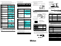
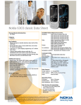
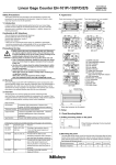
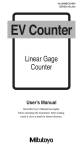
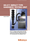
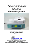
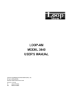
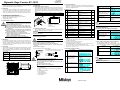
User’s Manual
No. 99MBC089A1
SERIES No. 542
Digimatic Gage Counter EC-101D
1. Safety Precautions
8.3 Setting parameters
8. Setup
To ensure operator safety, use the instrument in conformance with the
directions and specifications given in this manual.
8.1 Installation
8.1.1 Mounting counter on panel
After removing the fixing metals of the counter, insert the counter unit in
the panel from the front side and fix the counter from the rear side of the
panel using the fixing metals. Use the required number of washers
included with the EC-101D that are appropriate for the thickness of the
panel.
Panel thickness (mm) 1.0 to 1.3 1.4 to 1.7 1.8 to 2.5
2.5 to 3.2
Number of washers
0
1
2
3
2. Foreword
To obtain the highest performance and the longest service life from
your Counter, carefully read this User’s Manual thoroughly prior to
setup and operation. After reading this manual, keep it near the
Counter for quick reference. Be sure to follow the precautions below.
3. Conformance to EC Directives
This unit conforms to the following EC directives:
Standard: EN61326:1997+A1:1998 +A2:2001 +A3:2003
Immunity test requirement: Annex A
Emission limit: Class B
4. Precautions on Use
z Neither remove the cover nor disassemble this unit.
Doing so may expose personnel to electric shock or
result in damage or fire to this unit due to a short circuit
WARNING caused by metal chippings or dust.
z Note the warning labels on the top surface of this unit.
z This unit is a precision instrument. Do not bump or apply
excessive force to any part of this unit when setting it up
or operating it.
z Use this unit in an environment where the temperature is
between 0 and 40°C. Temperature variations should be
minimized so that there is no condensation.
z Avoid operating this unit in the following places:
• Where it will be exposed to cutting chips and oil, dirt,
dust, or significant vibrations.
• Where it will be exposed to direct sunlight.
• Near high-voltage/large current power equipment
Panel machining size
Thickness of panel that can be
mounted:
1 mm to 3.2 mm
8.1.2 Attaching rubber feet
When setting the counter on the desk, adhere the rubber feet included
with the counter to the bottom of the unit case.
CAUTION
Once the rubber feet have been adhered, the counter cannot be
mounted to the panel.
Be sure to disconnect the AC adapter plug before
connecting connectors.
If the Mitutoyo Digimatic Gage Counter (EC-101D) should prove
defective in workmanship or material, within one year from the date of
purchase, it will be repaired or replaced, at our option, free of charge
upon its prepaid return. For further information, contact your dealer or
local Mitutoyo sales office.
CAUTION
1) Connect the linear gage to the INPUT connector.
2) Connect the grounding wire to the grounding terminal.
3) Connect the cable to the OUT connector. The user must supply
the cable.
4) Connect the AC adapter.
6. Overview
The EC counter is a small counter conforming to the DIN size (96 × 48) that
allows for easy installation or incorporation. The EC counter features a
tolerance judgment or SDP output function. Gages with a Digimatic output
can be connected to.
Main features
Key function Presetting, zerosetting, tolerance limit setting
Tolerancing
3-stage tolerance limits
function
Output
Tolerancing output or Digimatic (switched by
function
parameter)
Input
Presetting hold (during tolerance mode)
function
<1>
<3>
How to install
the AC adapter
<9>
<5>
<6> <8> <7>
No.
Parameter Name
00
Parameter mode selection
To set parameters, select 1.
10
*1
11
User parameter clear
Initializes the user
parameters.
Count direction selection
12
Gage type setup
14
Startup mode
15
*1
16
mm/inch unit system display
selection
Not initialized by user
parameter clear.
(Inch = 1/25.4 mm)
Calculation with constant
17
Least significant digit blank
20
Digimatic output/tolerance
output switch
SDP equipment with
digimatic input wait
Key protect
Malfunction is prevented.
29
*5
35
Setting
0: Reference
1: Modification
(Settings other than 0 and 1 are
prohibited.)
1: Initialization
[Fn]
Initial
Setting
0
6
Press [Fn] to secure the
setting and move to the
next parameter number.
0
7
Repeat steps 3 and 4 for
required times.
Press [P.SET] while
holding down [Fn].
When the spindle is pushed in:
0: + count
1: − count
0: INC (LGS)
1: ABS (LGD, IDC, SD, etc.)
2: Multiple units connected *4
0: At startup “------” display
1: 0.000
0: mm
1: Inch 5/100,000 reads *2
2: Inch 1/10,000 reads *2
3: mm (when 1/100,000 inch gage
connected)
0: None
1: x2
2: x10
3: Arbitrary *3
0: Display all digits
1: Least significant digit blank
0: Tolerancing output
1: Digimatic output
0: No wait
1: 200 ms wait 2: 400 ms wait
0: Normal
1: Disable key input
0
8
1
The counter returns to the count
display mode to display a
counter value under the set
parameters.
0
Note
0
Unless parameter No. 00 is set to 1, no parameters can be
changed.
9. Setting Parameters
0
9.1 Turning on the AC adapter power supply
0
1
Procedure
1
0
0
2
*1. If this parameter is cleared, the preset value and tolerance limits are
cleared.
*2. When the inch type gage is connected, the minimum reading is the
resolution of the gage.
*3. For how to set the constant, refer to 10.
*4. The display speed can be changed.
When the Multi Unit is connected, set P. No. 12 = 2 and P. No. 29 =1.
Do not set the SELECT switch of the Multi Unit to “EX”.
*5. An error can occur when a special gage is connected. In such
cases, set P. No. 29 to 1 or 2.
Turn the counter on.
The counter enters the
count standby status.
Press [P.SET] to return to
the count display.
Key Operation/
Corresponding Display
[P.SET]
9.2 Zero setting, presetting, and error resetting
Use the [ZERO] or [P.SET] key to set the origin.
By presetting the [P.SET] key, the preset value can be changed (refer
to 9.4) and the origin (0 at factory setting) to the arbitrary value.
Procedure
Key Operation/
Corresponding Display
1) Parameter setting procedure
If an external DC power supply (option) is used,
connect the power cable as shown below.
+V
Approx. 8
Corresponding Display/Output
[P.SET]
Parameter list
1
Key Operation
Turn the counter on.
Corresponding Display/Output
The counter enters the count
standby status.
Press the [P.SET] key
while holding down the
[Fn] key to set the
parameter mode.
Displays the first parameter N o.
00. (The flashing digit can be
modified.)
−V
<4>
Key Operation
Press [P.SET] to set the
desired value.
1
Use the cord clamp to connect the AC adapter.
CAUTION
<2>
5
8.2 Connecting connectors
5. Warranty
7. Appearance
Set the counter parameters so they are appropriate for the gage to be
connected. Perform required settings such as switching between the
tolerance and Digimatic output.
Watch the following when using the EC-101D.
• Do not route the power cable and gage cable with other
power lines through the same piping.
• Use a shielded cable with a length of 3 m or less for the
OUTPUT cable.
• Be sure to ground the counter.
• Clamp all cables to the counter body.
<1> Tolerance limit indicator
<2> P. SET indicator
<3> UNIT indicator (flashes when the HOLD signal is input)
<4> Sign
<5> Gage input connector
<6> I/O connector
<7> AC adapter input
<8> Grounding terminal
<9> Cord clamp
2
Parameter No.
3
Press [P.SET] to set the
set value to 1.
[P.SET]
4
Press [Fn] to advance the
parameter number.
Press [Fn] twice.
Set value
The current setting parameter
11 will flash.
Kawasaki, Japan
2
Press [P.SET] or [ZERO]
When counter value is 1.000
[P.SET]
*If an error occurs, press the preset key to reset the error.
Note
z The preset count of the effective zero for the gage type (ABS) is 1
million times.
z After the error has been released, all of the decimal points flash for
approximately 8 seconds.
2) Tolerance judgment result
9.3 Setting preset value and tolerance limits
Always set the preset value and tolerance limits in this order.
flashing portions are indicated in gray in the following diagram.)
(The
1) Setting preset value and tolerance limits
Key Operation and Corresponding
Display/Output
1
Set the counter to the normal
count status.
Press [Fn] to enter the setup
[Fn] ON → OFF
mode.
2 The preset indicator flashes
and the preset value previously
set is shown.
[ZERO]
When [ZERO] is pressed, the
3
most significant digit will flash.
When tolerance limits have been set, the tolerance is judged in three steps
as shown in the table below.
Tolerance
Indicator
Measurement < Lower limit
Orange
Lower limit ≤ Measurement ≤ Upper limit Green
Upper limit < Measurement
Red
P.SET
Press [P.SET] ten times
Upper tolerance limit
−NG
GO
+NG
Surge absorbing diode
Output withstand voltage: 24 V max.
Output current: 20 mA max.
Output saturation voltage: 0.7 V max. Counter
TD62583 or
equivalent Output
Press [ON/OFF] to turn
the display off.
[ON/OFF]
(If the
Press [ON/OFF] again to
turn the display on. The
display at this time is as
follows according to the
gage type.
(ABS mode) When the
value is OFF.
(INC mode) Display value
such as ID
Press [ZERO] to move the
flashing digit.
Press [P.SET] five times
Press [Fn] to complete the
presetting of values.
[Fn]
After this, proceed to inputting
the lower tolerance limit.
7
When the tolerance indicator
lights orange, the displayed
value is the previously set
value.
Follow the procedures in 3 to 7
8
above to set the tolerance limit.
[Fn]
Press [Fn] to input the upper
tolerance limit.
When the tolerance indicator
lights red, the displayed value
is the previously set value.
[ON/OFF]
Description
Orange
1
2
Red
Press the [P.SET] key
while holding down the
[Fn] key.
3
Press [Fn] and then the
set constant is displayed.
4
Set the value following
the same procedure as
for presetting.
Press [Fn] to complete setting
and return to the count status.
5
Note
z Press [P.SET] to perform presetting.
z Setting tolerance values other than lower limit ≤ upper limit
results in an error. In this case, press [P.SET] to set the values
again.
Press [P.SET] while
holding down [Fn].
External device:
Reference circuit
Use an open-collector
output or relay output.
0.01 μF
<2>
P in
N o.
1
* When the arbitrary constant is set, the decimal point flashes.
11. Backup Memory Function
The following data is retained even if the power is turned off.
Parameters, preset value, Retained
tolerance limits
Counter value
Retained only during ABS mode
I/0
N am e
COM
2
3
4
O
O
O
5
6
I
I
Cause
Count standby status
at power on or
instantaneous power
interruption
Error10
Abnormal power
voltage
The counter value is 8
digits or more.
Abnormal gage
Error40
Tolerance output mode
<1>
Display
“-----” lights
Error30
12.3 Pin assignment
<9>
10 ms min.
14. Error Display
Operation: An input is valid when it is low.
OUT
10 ms min.
An input is active low: 1 = “H”, 0 = “L”
F*****
Applicable plug
MIL type connector
FAS-10-17 (YAMAICHI)
XG4M-1030-T (OMRON)
Error90
Error95
The counter value is 6
digits or more.
Tolerance limit setup
error
Key protection
Resetting Method
Press [P.SET].
The power supply needs to
be checked for an
instantaneous power
interruption.
Connect to the rated power
supply.
Change the present value
and press [P.SET].
Press [P.SET] and check
for correct gage
connection.
Change the preset value.
Press [P.SET] and input
tolerance limit again.
Set P. No. 35 to 0.
Note
1) During tolerance judgment mode
The display returns to the
counter value.
+NG
Use a surge absorbing diode or a relay with a built-in surge absorber
when using a relay to protect the output circuit.
<10>
Set value range: ±9.9999
*100 ms
PSET
Input current: I MAX 1 mA
Input voltage: H = 4 to 24 V
L = 1 V max.
Press [P.SET] twice to
set the set value to 2.
−NG
Note
+5 V
5 kΩ 5 kΩ
Key Operation/
Corresponding Display
The first parameter 00 is
displayed.
*100 ms
Attribute data
2) External preset HOLD
Counter
10. Setting Arbitrary Constant
Lower tolerance limit
* The time varies depending on the gage (the above value
shows a case of LGD).
COM
12.2 Input circuit
Press [P.SET] to change the
6
displayed value.
9
12.1 Output circuit
Operation: The transistor is turned on when the input is low.
(Open collector)
I/O Output
Follow the procedure below to turn the counter display on or off.
gage or I/O cable is connected, disconnect the AC adapter.)
Description
Key Operation/
Corresponding Display
1 Count status
Press [ZERO] twice
5
1) Tolerance output
9.4 ON/OFF
2
Press [P.SET] to change the
displayed value.
4 The most significant digit can
be set with a minus sign.
MSD: 0 → 9 → −0 → −9 → 0
13. Timing Chart
12. I/O Connector Terminal Function
F u n c tio n
In te rn a lly c o n n e c te d
to G N D
T o le ra n c e o u tp u t:
+NG
T h e c o rre s p o n d in g
GO
o u tp u t te rm in a l is lo w .
−N G
W h e n a n e rro r is
d is p la y e d
H O L D H O L D in p u t
P .S E T P re s e t in p u t (e rro r
c a n c e l)
N o c o n n e c tio n fo r
o th e r th a n a b o v e
O p tio n I/O
c a b le c o lo r
B ro w n /b la c k
B ro w n /re d
Y e llo w /b la c k
Y e llo w /re d
G re e n /b la c k
G re e n /re d
* The pin functions are different during the Digimatic output mode.
After setting the output mode, connect the cable.
* One end of the I/O cable is not bunched and requires processing by
users. Connect the F.G line to the grounding terminal of the
counter. Connect the F.G terminal (with green solderless terminal)
of the cable to the earth terminal of the counter.
z During tolerance output, ±NG is low.
z If an error occurs during parameters, preset values, or tolerance
limit settings, an error is displayed after the counter has returned to
the count status. However, the error is immediately output to the
external output device.
15. Specifications
Code No.
Model
Number of display
axes
Power supply
Power consumption
Operating
temperature
Storage temperature
External dimensions
(W × D × H)
Mass
542-007
EC-101D
One axis
+9 V to +12 V (400 mA max.)
4.8 VA
0 to 40°C (20 to 80% RH with no condensation)
−10 to 50°C (20 to 80% RH with no condensation)
96 × 84.6 × 48 mm
220 g
16. Standard Accessories
Order No.
−
−
526688
99MBC089J
Part Name
Washer (plain washer: nominal dia. 4)
Rubber feet
AC adapter (AD908N)
User’s Manual (this document)
Warranty card
Quantity
6
4
1
1
1
17. Optional Accessories (Separate Order)
Order No.
936937
965014
214938
C162-155
Part Name
Connecting cable for Digimatic mini processor (1 m)
Connecting cable for Digimatic mini processor (2 m)
PJ-2 (DC plug)
I/O cable (2 m)