1
2001 FORESTER SERVICE MANUAL
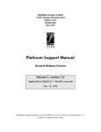
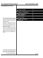
QUICK REFERENCE INDEX
TRANSMISSION SECTION
This service manual has been prepared
to provide SUBARU service personnel
with the necessary information and data
for the correct maintenance and repair of
SUBARU vehicles.
This manual includes the procedures for
maintenance, disassembling, reassembling, inspection and adjustment of components and diagnostics for guidance of
experienced mechanics.
Please peruse and utilize this manual
fully to ensure complete repair work for
satisfying our customers by keeping their
vehicle in optimum condition. When
replacement of parts during repair work is
needed, be sure to use SUBARU genuine parts.
All information, illustration and specifications contained in this manual are based
on the latest product information available at the time of publication approval.
FUJI HEAVY INDUSTRIES LTD.
G8050GE4
AUTOMATIC TRANSMISSION
(DIAGNOSTICS)
AT
1.
2.
3.
4.
5.
6.
7.
8.
9.
10.
11.
12.
13.
14.
15.
16.
Page
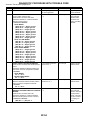
Basic Diagnostic Procedure ........................................................................2
Check List for Interview...............................................................................4
General Description.....................................................................................5
Electrical Components Location..................................................................8
Transmission Control Module (TCM) I/O Signal .......................................15
Subaru Select Monitor...............................................................................20
Read Diagnostic Trouble Code .................................................................22
Inspection Mode ........................................................................................24
Clear Memory Mode..................................................................................25
Power Indicator Light Display ...................................................................26
List of Diagnostic Trouble Code................................................................27
Diagnostic Procedure for Power Indicator Light .......................................28
Diagnostic Procedure for Select Monitor Communication ........................36
Diagnostic Procedure with Trouble Code .................................................42
Diagnostic Procedure for No-trouble Code.............................................107
Symptom Related Diagnostic..................................................................134
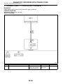
BASIC DIAGNOSTIC PROCEDURE
Automatic Transmission (Diagnostics)
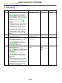
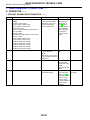
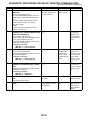
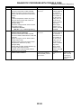
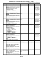
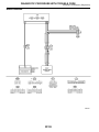
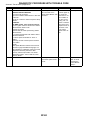
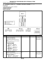
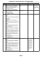
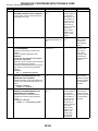
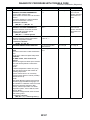
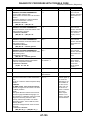
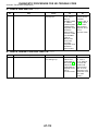
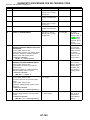
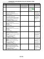
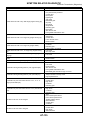
1. Basic Diagnostic Procedure
A: PROCEDURE
No.
1
2
3
4
S004501
S004501E45
Step
CHECK PRE-INSPECTION.
1) Ask the customer when and how the
trouble occurred using interview checklist.
<Ref. to AT-4, Check List for Interview.>
2) Before performing diagnosis, inspect the
following items which might influence the AT
problems.
쐌 General inspection <Ref. to AT-5,
INSPECTION, General Description.>
쐌 Oil leak
쐌 Stall speed test <Ref. to AT-13, Stall Test.>
쐌 Line pressure test <Ref. to AT-16, Line
Pressure Test.>
쐌 Transfer clutch pressure test <Ref. to
AT-18, Transfer Clutch Pressure Test.>
쐌 Time lag test <Ref. to AT-15, Time Lag
Test.>
쐌 Road test <Ref. to AT-12, Road Test.>
쐌 Inhibitor switch <Ref. to AT-28, Inhibitor
Switch.>
CHECK POWER INDICATOR LIGHT.
Turn ignition switch to ON.
CHECK POWER INDICATOR LIGHT.
1) Turn ignition switch to OFF.
2) Repair POWER indicator light circuit or
power supply and ground line circuit.
<Ref. to AT-28, Diagnostic Procedure for
Power Indicator Light.>
3) Turn ignition switch to ON.
CHECK INDICATION OF TROUBLE CODE.
Calling up trouble code.
Without SUBARU SELECT MONITOR
<Ref. to AT-22, WITHOUT SUBARU SELECT
MONITOR, OPERATION, Read Diagnostic
Trouble Code.>
With SUBARU SELECT MONITOR
<Ref. to AT-23, WITH SUBARU SELECT
MONITOR, OPERATION, Read Diagnostic
Trouble Code.>
NOTE:
If the communication function of the select
monitor cannot be executed normally, check
the communication circuit. <Ref. to AT-36,
COMMUNICATION FOR INITIALIZING
IMPOSSIBLE, Diagnostic Procedure for
Select Monitor Communication.>
Check
Is unit that might influence
the AT problem normal?
Yes
Go to step 2.
No
Repair or replace
each item.
Does not the POWER indicator light light up?
Is the POWER indicator
light flashing?
Go to step 3.
Go to step 4.
Go to step 4.
Go to step 5.
Is the trouble code displayed?
Go to step 6.
NOTE:
Record all trouble
codes.
Go to step 5.
AT-2
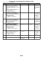
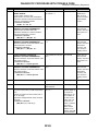
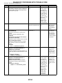
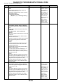
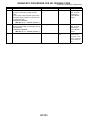
BASIC DIAGNOSTIC PROCEDURE
Automatic Transmission (Diagnostics)
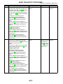
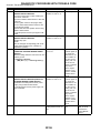
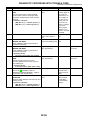
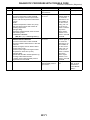
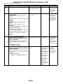
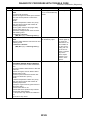
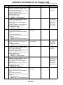
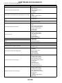
No.
5
6
Step
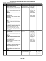
PERFORM THE GENERAL DIAGNOSTICS.
1) Inspect using “Diagnostic Procedure for
No-trouble Code”.<Ref. to AT-107, Diagnostic
Procedure for No-trouble Code.>
2) Inspect using “Symptom Related Diagnostic”. <Ref. to AT-134, Symptom Related Diagnostic.>
3) Perform the clear memory mode.
With SUBARU SELECT MONITOR
<Ref. to AT-25, WITH SUBARU SELECT
MONITOR, OPERATION, Clear Memory
Mode.>
Without SUBARU SELECT MONITOR
<Ref. to AT-25, WITHOUT SUBARU SELECT
MONITOR, OPERATION, Clear Memory
Mode.>
4) Perform the inspection mode. <Ref. to
AT-24, Inspection Mode.>
Calling up the trouble code.
Without SUBARU SELECT MONITOR
<Ref. to AT-22, WITHOUT SUBARU SELECT
MONITOR, OPERATION, Read Diagnostic
Trouble Code.>
With SUBARU SELECT MONITOR
<Ref. to AT-23, WITH SUBARU SELECT
MONITOR, OPERATION, Read Diagnostic
Trouble Code.>
PERFORM THE DIAGNOSIS.
1) Inspect using “Diagnostics Chart with
Trouble Code”.<Ref. to AT-42, Diagnostic Procedure with Trouble Code.>
NOTE:
For trouble code table, refer to “List of Diagnostic Trouble Code”.<Ref. to AT-27, List of
Diagnostic Trouble Code.>
2) Repair trouble cause.
3) Perform the clear memory mode.
With SUBARU SELECT MONITOR
<Ref. to AT-25, WITH SUBARU SELECT
MONITOR, OPERATION, Clear Memory
Mode.>
Without SUBARU SELECT MONITOR
<Ref. to AT-25, WITHOUT SUBARU SELECT
MONITOR, OPERATION, Clear Memory
Mode.>
4) Perform the inspection mode. <Ref. to
AT-24, Inspection Mode.>
5) Calling up the trouble code.
Without SUBARU SELECT MONITOR
<Ref. to AT-22, WITHOUT SUBARU SELECT
MONITOR, OPERATION, Read Diagnostic
Trouble Code.>
With SUBARU SELECT MONITOR
<Ref. to AT-23, WITH SUBARU SELECT
MONITOR, OPERATION, Read Diagnostic
Trouble Code.>
Check
Is the trouble code displayed?
Yes
Go to step 6.
Is the trouble code displayed?
Complete the
Inspect using
“Diagnostics Chart diagnosis.
with Diagnostic
Connector”. <Ref.
to AT-42, Diagnostic Procedure with
Trouble Code.>
AT-3
No
Complete the
diagnosis.
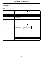
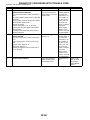
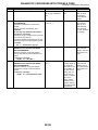
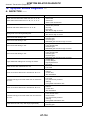
CHECK LIST FOR INTERVIEW
Automatic Transmission (Diagnostics)
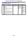
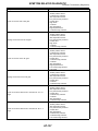
2. Check List for Interview
A: CHECK
S004502
S004502A04
Check the following items when problem has occurred.
NOTE:
Use copies of this page for interviewing customers.
Customer’s name
Data vehicle brought in
Data of repair
Trans. model
Odometer reading
Frequency
Weather
Place
Outdoor temperature
Vehicle speed
Malfunction indicator lamp (MIL)
Select lever position
Driving condition
POWER switch
HOLD switch
Symptoms
TRANSMISSION
VIN
km/h or mile
쏔
쏔
쏔
(
쏔
쏔
(
쏔
Continuous 쏔 Intermittent (
times a day)
Fine 쏔 Cloudy 쏔 Rainy 쏔 Snowy
Various/Others
)
Highway 쏔 Suburbs 쏔 Inner city 쏔 Uphill
Others
)
Hot 쏔 Warm 쏔 Cool 쏔 Cold
쏔 Rough road
km/h (MPH)
쏔 Continuously lit
쏔P 쏔R 쏔N 쏔D
쏔 Not affected
쏔 At racing
쏔 While decelerating
쏔
쏔
쏔
쏔
쏔
쏔
쏔
쏔
쏔
쏔
쏔
(
쏔 Not lit
쏔3 쏔2 쏔1
쏔 At starting
쏔 While accelerating
쏔 While turning (쏔 RH/쏔
LH)
ON 쏔 OFF
ON 쏔 OFF
No up-shift
No down-shift
No kick down
Vehicle does not move (쏔 Any position
Lock-up malfunction
Noise or vibration
Shift shock or slip
Select lever does not move
Others
)
AT-4
쏔 While idling
쏔 While cruising
쏔 Particular position)
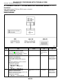
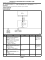
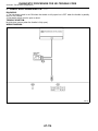
GENERAL DESCRIPTION
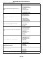
3. General Description
A: CAUTION
Automatic Transmission (Diagnostics)
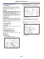
3. ATF LEVEL
S004001
S004001A1003
Make sure that ATF level is in the specification.
S004001A03
쐌 Supplemental Restraint System “Airbag”
Airbag system wiring harness is routed near the
transmission control module (TCM).
CAUTION:
쐌 All airbag system wiring harness and connectors are colored yellow. Do not use electrical test equipment on these circuit.
쐌 Be careful not to damage airbag system wiring harness when performing diagnostics and
servicing the TCM.
쐌 Measurement
When measuring voltage and resistance of the
ECM, TCM or each sensor, use a tapered pin with
a diameter of less than 0.64 mm (0.025 in) in order
to avoid poor contact. Do not insert the pin more
than 6.5 mm (0.256 in).
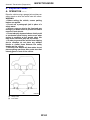
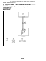
B: INSPECTION
1. BATTERY
B3M0173B
(A)
(B)
Upper level
Lower level
4. FRONT DIFFERENTIAL OIL LEVEL
S004001A1004
Make sure that front differential oil level is in the
specification.
S004001A10
S004001A1001
Measure battery voltage and specific gravity of
electrolyte.
Standard voltage: 12V or more
Specific gravity: Above 1.260
2. TRANSMISSION GROUND
S004001A1002
Make sure that the ground terminal bolt is tightened securely.
쐌 Chassis side
Tightening torque:
13 N·m (1.3 kgf-m, 9.4 ft-lb)
TR0373
AT-5
B3M0174B
(A)
(B)
Upper level
Lower level
Automatic Transmission (Diagnostics)
GENERAL DESCRIPTION
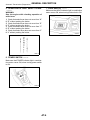
5. OPERATION OF SHIFT SELECT LEVER
7. HOLD SWITCH
S004001A1005
WARNING:
Stop the engine while checking operation of
select lever.
Make sure that HOLD indicator light in combination
meter comes ON, when turning hold switch to ON.
1) Check that select lever does not move from “N”
to “R” without pushing the button.
2) Check that select lever does not move from “R”
to “P” without pushing the button.
3) Check that select lever does not move from “P”
to “R” without pushing the button.
4) Check that select lever does not move from “3”
to “2” without pushing the button.
G3M0717
6. POWER SWITCH
S004001A1007
S004001A1006
Make sure that POWER indicator light in combination meter comes ON, when turning power switch
to ON.
S3M0449
AT-6
S3M0117
GENERAL DESCRIPTION
C: PREPARATION TOOL
1. SPECIAL TOOLS
Automatic Transmission (Diagnostics)
S004001A17
S004001A1701
ILLUSTRATION
TOOL NUMBER
DESCRIPTION
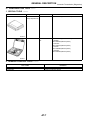
24082AA150
CARTRIDGE
(Newly adopted tool)
REMARKS
Troubleshooting for electrical systems.
B2M3876
22771AA030
SELECT MONITOR
KIT
Troubleshooting for electrical systems.
쐌 English:
22771AA030 (Without printer)
쐌 German:
22771AA070 (Without printer)
쐌 French:
22771AA080 (Without printer)
쐌 Spanish:
22771AA090 (Without printer)
B2M3877
2. GENERAL PURPOSE TOOLS
TOOL NAME
Circuit Tester
Oscilloscope
S004001A1702
REMARKS
Used for measuring resistance, voltage and ampere.
Used for measuring sensor.
AT-7
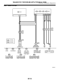
ELECTRICAL COMPONENTS LOCATION
Automatic Transmission (Diagnostics)
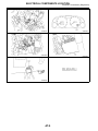
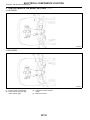
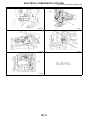
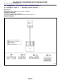
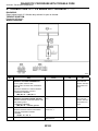
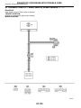
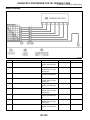
4. Electrical Components Location
A: LOCATION
S004507
S004507A13
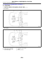
1. CONTROL MODULE FOR MODEL WITHOUT OBD
S004507A1304
쐌 LHD MODEL
S3M0134A
쐌 RHD MODEL
S3M0133A
(1) Engine control module (ECM)
(2) Power indicator light (AT diagnostic indicator light)
(3) Transmission control module
(TCM)
(4) Data link connector
AT-8
ELECTRICAL COMPONENTS LOCATION
Automatic Transmission (Diagnostics)
S2M0533C
S3M0590A
B3M1592B
B3M1652A
S2M0258C
AT-9
ELECTRICAL COMPONENTS LOCATION
Automatic Transmission (Diagnostics)
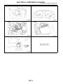
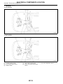
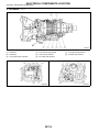
2. CONTROL MODULE FOR MODEL WITH OBD
S004507A1305
쐌 LHD MODEL
S3M0240A
쐌 RHD MODEL
S3M0241A
(1) Engine control module (ECM)
(2) Power indicator light (AT diagnostic indicator light)
(3) Transmission control module
(TCM)
(4) Data link connector
AT-10
ELECTRICAL COMPONENTS LOCATION
Automatic Transmission (Diagnostics)
B3M0183E
S3M0590A
B3M1592B
B3M1652A
S2M0258C
AT-11
ELECTRICAL COMPONENTS LOCATION
Automatic Transmission (Diagnostics)
3. SENSOR
S004507A1302
쐌 LHD MODEL
S3M0240C
쐌 RHD MODEL
S3M0241C
(1) Throttle position sensor
(2) Front vehicle speed sensor
(3) Inhibitor switch
(4) Rear vehicle speed sensor
(5) Torque converter torbine speed
sensor
AT-12
(6) ATF temperature sensor
ELECTRICAL COMPONENTS LOCATION
Automatic Transmission (Diagnostics)
S2M0262B
TR0387
TR0388
TR0390
TR0389
AT-13
ELECTRICAL COMPONENTS LOCATION
Automatic Transmission (Diagnostics)
4. SOLENOID
S004507A1303
B3M1186A
(1) Solenoid 1
(2) Solenoid 2
(3) Line pressure duty solenoid
(4) Low clutch timing solenoid
(5) Lock-up duty solenoid
(6) 2-4 brake duty solenoid
B2M2263D
AT-14
(7) 2-4 brake timing solenoid
(8) Transfer duty solenoid
B2M2264E
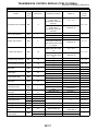
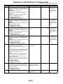
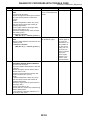
TRANSMISSION CONTROL MODULE (TCM) I/O SIGNAL
Automatic Transmission (Diagnostics)
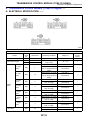
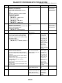
5. Transmission Control Module (TCM) I/O Signal
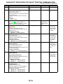
A: ELECTRICAL SPECIFICATION
S004506
S004506A08
TR0532
Check with ignition switch ON.
Content
Back-up power supply
Ignition power supply
“P” range
switch
Inhibitor
switch
Brake switch
Connector
No.
B56
B54
B54
B55
Terminal No.
Measuring conditions
Voltage (V)
1
23
24
Ignition switch OFF
10 — 16
Resistance
to body
(ohms)
—
Ignition switch ON (with
engine OFF)
10 — 16
—
1
“N” range
switch
B55
14
“R” range
switch
B55
3
“D” range
switch
B55
4
“3” range
switch
B55
5
“2” range
switch
B55
6
“1” range
switch
B55
7
B55
12
Select lever in “P” range
Select lever in any other
than “P” range (except “N”
range)
Select lever in “N” range
Select lever in any other
than “N” range (except “P”
range)
Select lever in “R” range
Select lever in any other
than “R” range
Select lever in “D” range
Select lever in any other
than “D” range
Select lever in “3” range
Select lever in any other
than “3” range
Select lever in “2” range
Select lever in any other
than “2” range
Select lever in “1” range
Select lever in any other
than “1” range
Brake pedal depressed.
Brake pedal released.
AT-15
Less than 1
More than 8
—
Less than 1
More than 8
—
Less than 1
More than 8
—
Less than 1
More than 8
—
Less than 1
More than 8
—
Less than 1
More than 8
—
Less than 1
More than 8
More than 10.5
Less than 1
—
—
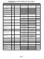
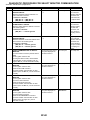
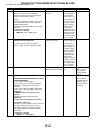
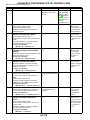
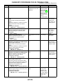
TRANSMISSION CONTROL MODULE (TCM) I/O SIGNAL
Automatic Transmission (Diagnostics)
Check with ignition switch ON.
Connector
No.
Terminal No.
Kick-down switch
B55
11
AT OIL TEMP warning light
B56
10
Throttle position sensor
B54
3
Throttle position sensor
power supply (with OBD
model)
B54
2
Content
ATF temperature sensor
B54
11
Rear vehicle speed sensor
B55
24
Front vehicle speed sensor
B55
18
Torque converter turbine
speed sensor
B55
8
Vehicle speed output signal
(Waveform)
B56
17
Engine speed signal
B55
17
Cruise set signal
B55
22
Torque control signal 1
B56
5
Torque control signal 2
B56
14
Torque control cut signal
Intake manifold pressure
signal (Non-turbo model)
Mass air flow signal (Turbo
model)
B55
10
B54
1
B54
1
Shift solenoid 1
B54
22
Shift solenoid 2
B54
5
Measuring conditions
Voltage (V)
Throttle fully open.
Throttle fully closed.
Light ON
Light OFF
Throttle fully closed.
Throttle fully open.
Less than 1
More than 6.5
Less than 1
More than 9
0.3 — 0.7
4.0 — 4.6
Ignition switch ON (With
engine OFF)
4.8 — 5.3
ATF temperature 20°C
1.6 — 2.0
(68°F)
ATF temperature 80°C
0.4 — 0.9
(176°F)
Vehicle stopped.
0
Vehicle speed at least 20
More than 1 (AC range)
km/h (12 MPH)
Vehicle stopped.
0
Vehicle speed at least 20
More than 1 (AC range)
km/h (12 MPH)
Engine idling after warm0
up. (D range)
Engine idling after warmMore than 1 (AC range)
up. (N range)
Vehicle speed at most 10
Less than 1←
km/h (6 MPH)
→More than 4
Ignition switch ON (with
More than 10.5
engine OFF)
Ignition switch ON (with
8 — 11
engine ON)
When cruise control is set
Less than 1
(SET lamp ON)
When cruise control is not
More than 6.5
set (SET lamp OFF)
Ignition switch ON (with
More than 4
engine ON)
Ignition switch ON (with
More than 4
engine ON)
Ignition switch ON
8
Engine idling after warm1.2 — 1.8
up.
Engine idling after warm0.5 — 1.2
up.
1st or 4th gear
More than 9
2nd or 3rd gear
Less than 1
1st or 2nd gear
More than 9
3rd or 4th gear
Less than 1
AT-16
Resistance
to body
(ohms)
—
—
—
—
2.1 k — 2.9
k
275 — 375
450 — 650
450 — 650
450 — 650
—
—
—
—
—
—
—
—
10 — 16
10 — 16
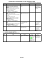
TRANSMISSION CONTROL MODULE (TCM) I/O SIGNAL
Automatic Transmission (Diagnostics)
Check with ignition switch ON.
Content
Line pressure duty solenoid
Connector
No.
B54
Terminal No.
9
Lock-up duty solenoid
B54
7
Transfer duty solenoid
B54
6
2-4 brake duty solenoid
B54
18
Measuring conditions
Ignition switch ON (with
engine OFF)
Throttle fully closed after
warm-up.
Ignition switch ON (with
engine OFF)
Throttle fully open after
warm-up.
When lock up occurs.
When lock up is released.
Fuse on FWD switch
Fuse removed from FWD
switch (with throttle fully
open and with select lever
in 1st gear).
Throttle fully closed (with
engine OFF) after warmup.
Throttle fully open (with
engine OFF) after warmup.
1st gear
3rd gear
2nd gear
4th gear
Hold switch ON
Hold switch OFF
Power switch ON
Power switch OFF
Light ON
Light OFF
Fuse removed
Fuse installed
Fused ON FWD switch
Fuse removed from FWD
switch
ABS switch ON
ABS switch OFF
—
—
2-4 brake timing solenoid
B54
16
Low clutch timing solenoid
B54
15
Hold switch
B55
16
Power switch
B55
23
Power indicator light
B56
11
FWD switch
B55
20
FWD indicator light
B56
2
ABS signal
B55
21
Sensor ground line 1
Sensor ground line 2
B54
B55
B56
B54
B54
B54
20
9
19
21
10
19
B56
21
Ignition switch ON
B56
15
6
—
—
System ground line
Sensor ground line 3
Sensor ground line 4
AT diagnosis signal (Waveform)
Data link signal (Subaru
Select Monitor)
AT-17
Voltage (V)
Resistance
to body
(ohms)
1.5 — 4.0
2.0 — 4.5
Less than 0.5
More than 8.5
Less than 0.5
More than 8.5
Less than 0.5
10 — 17
10 — 17
1.5 — 4.0
2.0 — 4.5
Less than 0.5
Less than 1
More than 9
Less than 1
More than 9
Less than 1
More than 8
Less than 1
More than 10
Less than 1
More than 9
6 — 9.1
Less than 1
Less than 1
10 — 16
10 — 16
—
—
—
—
—
—
—
—
—
More than 9
—
Less than 1
6.5 — 15
0
0
—
—
Less than 1
Less than 1
—
0
Less than 1
—
—
0
0
Less than 1 ←
→ More than 4
—
—
Less than 1
Less than 1
—
—
TRANSMISSION CONTROL MODULE (TCM) I/O SIGNAL
Automatic Transmission (Diagnostics)
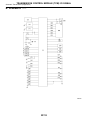
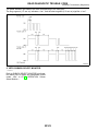
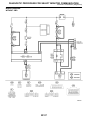
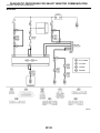
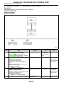
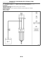
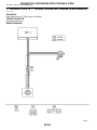
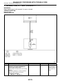
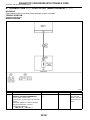
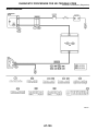
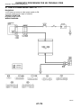
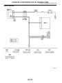
B: SCHEMATIC
S004506A21
S3M0620
AT-18
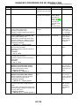
TRANSMISSION CONTROL MODULE (TCM) I/O SIGNAL
Automatic Transmission (Diagnostics)
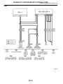
(1) Transmission control module
(2) Data link connector
(3) Cruise control module (Nonturbo model)
(4) ABS control module
(5) Ignition switch
(6) Brake switch
(7) Brake light
(8) Battery
(9) Combination meter (Speedometer circuit)
(10) ATF temperature warning light
(11) FWD indicator light
(12) POWER indicator light
(13) HOLD indicator light
(14) FWD switch
(15)
(16)
(17)
(18)
(19)
(20)
(21)
(22)
(23)
(24)
(25)
(26)
(27)
(28)
(29)
(30)
Kick-down switch
Power switch
Hold switch
“P” range switch
“R” range switch
“N” range switch
“D” range switch
“3” range switch
“2” range switch
“1” range switch
Throttle position sensor
Engine speed signal
Torque control cut signal
Torque control signal 2
Torque control signal 1
AT load signal
AT-19
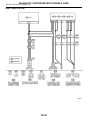
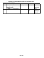
(31)
(32)
(33)
(34)
(35)
(36)
(37)
(38)
(39)
(40)
(41)
(42)
(43)
(44)
AT diagnostic signal (with OBD)
Engine control module
ATF temperature sensor
Torque converter turbine speed
sensor
Vehicle speed sensor 2 (Front)
Vehicle speed sensor 1 (Rear)
Shift solenoid 1
Shift solenoid 2
2-4 brake timing solenoid
Line pressure duty solenoid
2-4 brake duty solenoid
Lock-up duty solenoid
Low clutch timing solenoid
Transfer duty solenoid
SUBARU SELECT MONITOR
Automatic Transmission (Diagnostics)
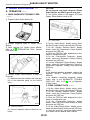
6. Subaru Select Monitor
A: OPERATION
CAUTION:
Do not connect scan tools except for Subaru
Select Monitor and OBD-II general scan tool.
S004503
S004503A16
5) Turn ignition switch to ON (engine OFF) and
Subaru Select Monitor switch to ON.
1. READ DIAGNOSTIC TROUBLE CODE
S004503A1601
1) Prepare Subaru Select Monitor kit.
S2M0288C
(A)
S2M0285
2) Connect diagnosis cable to Subaru Select
Monitor.
3) Insert cartridge into Subaru Select Monitor.
<Ref. to AT-7, PREPARATION TOOL, General
Description.>
S2M0286
4) Connect Subaru Select Monitor to data link
connector.
(1) Data link connector located in the lower portion of the instrument panel (on the driver’s
side).
Power switch
6) On the ⰆMain MenuⰇ display screen, select
the {Each System Check} and press the [YES] key.
7) On the ⰆSystem Selection MenuⰇ display
screen, select the {Transmission Control System}
and press the [YES] key.
8) Press the [YES] key after displayed the information of transmission type.
9) On the ⰆTransmission DiagnosisⰇ display
screen, select the {Diagnostic Code(s) Display}
and press the [YES] key.
10) On the ⰆDiagnostic Code(s) DisplayⰇ display
screen, select the {Latest Diagnostic Code(s)} or
{Memorized Diagnostic Code(s)} and press the
[YES] key.
NOTE:
쐌 For detailed operation procedure, refer to the
SUBARU SELECT MONITOR OPERATION
MANUAL.
쐌 For detailed concerning diagnostic trouble
codes, refer to the DIAGNOSTIC TROUBLE
CODE LIST. <Ref. to AT-27, List of Diagnostic
Trouble Code.>
2. READ CURRENT DATA
BR0033
(A)
Data link connector
(2) Connect diagnosis cable to data link connector.
S004503A1602
1) On the ⰆMain MenuⰇ display screen, select
the {Each System Check} and press the [YES] key.
2) On the ⰆSystem Selection MenuⰇ display
screen, select the {Transmission Control System}
and press the [YES] key.
3) Press the [YES] key after displayed the information of transmission type.
4) On the ⰆTransmission DiagnosisⰇ display
screen, select the {Current Data Display & Save}
and press the [YES] key.
5) On the ⰆData Display MenuⰇ display screen,
select the {Data Display} and press the [YES] key.
6) Using the scroll key, move the display screen
up or down until the desired data is shown.
AT-20
SUBARU SELECT MONITOR
Automatic Transmission (Diagnostics)
쐌 A list of the support data is shown in the following table.
Contents
Battery voltage
Rear vehicle speed sensor signal
Front vehicle speed sensor signal
Engine speed signal
Automatic transmission fluid temperature signal
Throttle position signal
Gear position
Line pressure control duty ratio
Lock up clutch control duty ratio
Transfer clutch control duty ratio
Power supply for throttle position sensor
Torque converter turbine speed signal
2-4 brake timing pressure control duty ratio
Intake manifold pressure sensor voltage
2 wheel drive switch signal
Stop lamp switch signal
Anti lock brake system signal
Cruise control system signal
Neutral/Parking range signal
Reverse range signal
Drive range signal
3rd range signal
2nd range signal
1st range signal
Shift control solenoid A
Shift control solenoid B
Torque control output signal #1
Torque control output signal #2
Torque control cut signal
2-4 brake timing control solenoid valve
Low clutch timing control solenoid valve
Automatic transmission diagnosis indicator lamp
Power mode switch signal
Hold mode switch signal
Kick down switch signal
Automatic transmission fluid temperature lamp
Display
Battery Voltage
Rear Wheel Speed
Front Wheel Speed
Engine Speed
ATF Temp.
Throttle Sensor Voltage
Gear Position
Line Pressure Duty Ratio
Lock Up Duty Ratio
Transfer Duty Ratio
Throttle Sensor Power
Turbine Revolution Speed
Brake Clutch Duty Ratio
Mani. Pressure Voltage
FWD Switch
Stop Light Switch
ABS Signal
Cruise Control Signal
N/P Range Signal
R Range Signal
D Range Signal
3rd Range Signal
2nd Range Signal
1st Range Signal
Shift Solenoid #1
Shift Solenoid #2
Torque Control Signal 1
Torque Control Signal 2
Torque Control Cut Sig.
2-4 Brake Timing Sol.
Low Clutch Timing Sol.
Diagnosis Lamp
Power Mode Switch
Hold Mode Switch
Kick Down Switch
ATF Temperature Lamp
Unit of measure
V
km/h or MPH
km/h or MPH
rpm
°C or °F
V
—
%
%
%
V
rpm
%
V
ON or OFF
ON or OFF
ON or OFF
ON or OFF
ON or OFF
ON or OFF
ON or OFF
ON or OFF
ON or OFF
ON or OFF
ON or OFF
ON or OFF
ON or OFF
ON or OFF
ON or OFF
ON or OFF
ON or OFF
ON or OFF
ON or OFF
ON or OFF
ON or OFF
ON or OFF
NOTE:
For detailed operation procedure, refer to the SUBARU SELECT MONITOR OPERATION MANUAL.
3. CLEAR MEMORY MODE
S004503A1603
1) On the ⰆMain MenuⰇ display screen, select
the {2. Each System Check} and press the [YES]
key.
2) On the ⰆSystem Selection MenuⰇ display
screen, select the {Transmission Control System}
and press the [YES] key.
3) Press the [YES] key after displayed the information of transmission type.
4) On the ⰆTransmission DiagnosisⰇ display
screen, select the {Clear Memory} and press the
[YES] key.
5) When the ‘Done’ and ‘Turn Ignition Switch OFF’
are shown on the display screen, turn the Subaru
Select Monitor and ignition switch to OFF.
NOTE:
For detailed operation procedure, refer to the
SUBARU SELECT MONITOR OPERATION
MANUAL.
AT-21
READ DIAGNOSTIC TROUBLE CODE
Automatic Transmission (Diagnostics)
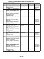
7. Read Diagnostic Trouble Code
A: OPERATION
S004508A16
1. WITHOUT SUBARU SELECT MONITOR
No.
2
Step
PERFORM READ DIAGNOSTIC TROUBLE
CODE.
1) Warm-up the engine.
2) Turn ignition switch to OFF.
3) Turn ignition switch to ON.
4) Start the engine.
5) Drive vehicle at speeds greater than 20
km/h (12 MPH).
6) Stop vehicle.
7) Brake pedal depressed and move select
lever to 1 range.
8) Turn ignition switch to OFF.
9) Turn ignition switch to ON.
10) Move select lever 2 range.
11) Move select lever 1 range.
12) Move select lever 2 range.
13) Move select lever 3 range.
14) Move select lever D range.
CHECK INDICATOR LIGHT.
3
CHECK INDICATOR LIGHT.
4
CHECK INDICATOR LIGHT.
1
S004508
S004508A1601
Check
Does indicator light blinks
at 4-Hz intervals? NOTE:
Blinks every 0.125 (1/8)
seconds (until ignition
switch is turned OFF).
Yes
No
Repair power sup- Go to step 2.
ply and ground
circuit.<Ref. to
AT-32, CHECK
POWER SUPPLY
AND GROUND
LINE, Diagnostic
Procedure for
Power Indicator
Light.>
AT system is norDoes indicator light blinks
mal.
at 2-Hz intervals?
NOTE:
Blinks every 0.25 (1/4) seconds (until ignition switch is
turned OFF).
Is trouble code outputted? Inspect problem
corresponding
with trouble code.
NOTE:
Record all trouble
codes.
Does indicator light
Repair power indiremains illuminated?
cator light circuit
<Ref. to AT-28,
Diagnostic Procedure for Power
Indicator Light.>,
or Inspect inhibitor
switch, wiring,
TCM, etc.
AT-22
Go to step 3.
Go to step 4.
Calling up trouble
code again.
READ DIAGNOSTIC TROUBLE CODE
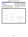
Automatic Transmission (Diagnostics)
The power indicator light flashes the code corresponding to the faulty part.
The long segment (1.2 sec on) indicates a “ten”, and the short segment (0.2 sec on) signifies a “one”.
B3M1199A
2. WITH SUBARU SELECT MONITOR
S004508A1602
Refer to SUBARU SELECT MONITOR for information about how to obtain and understand trouble
codes. <Ref. to AT-20, OPERATION, Subaru
Select Monitor.>
AT-23
Automatic Transmission (Diagnostics)
8. Inspection Mode
A: OPERATION
INSPECTION MODE
S004510
S004510A16
Raise the vehicle using a garage jack and place on
safety stands or drive the vehicle onto free rollers.
WARNING:
쐌 Before raising the vehicle, ensure parking
brakes are applied.
쐌 Do not use a pantograph jack in place of a
safety stand.
쐌 Secure a rope or wire to the front and rear
towing or tie-down hooks to prevent the lateral
runout of front wheels.
쐌 Do not abruptly depress/release clutch pedal
or accelerator pedal during works even when
engine is operating at low speeds since this
may cause vehicle to jump off free rollers.
쐌 In order to prevent the vehicle from slipping
due to vibration, do not place any wooden
blocks or similar items between the safety
stands and the vehicle.
쐌 Since the rear wheels will also rotate, do not
place anything near them. Also, make sure that
nobody goes in front of the vehicle.
B2M2969C
(A)
(B)
Safety stand
Free rollers
AT-24
CLEAR MEMORY MODE
9. Clear Memory Mode
A: OPERATION
S004513
S004513A16
1. WITHOUT SUBARU SELECT MONITOR
S004513A1602
Current trouble codes shown on the display are
cleared by turning the ignition switch OFF after
conducting on-board diagnostics operation. Previous trouble codes, however, cannot be cleared
since they are stored in the TCM memory which is
operating on the back-up power supply. These
trouble codes can be cleared by removing the
specified fuse (located under the light or left lower
position of the instrument panel).
CLEAR MEMORY:
Removal of No. 4 fuse (for at least one
minute)
쐌 The No. 4 fuse is located in the line to the
memory back-up power supply of the TCM.
Removal of this fuse clears the previous trouble
codes stored in the TCM memory.
쐌 Be sure to remove the No. 4 fuse for at least the
specified length of time. Otherwise, trouble codes
may not be cleared.
2. WITH SUBARU SELECT MONITOR
S004513A1601
Refer to SUBARU SELECT MONITOR for information about how to clear trouble codes.
<Ref. to AT-21, CLEAR MEMORY MODE,
OPERATION, Subaru Select Monitor.>
AT-25
Automatic Transmission (Diagnostics)
POWER INDICATOR LIGHT DISPLAY
Automatic Transmission (Diagnostics)
10. Power Indicator Light
Display
S004729
A: INSPECTION
S004729A10
When any on-board diagnostics item is
malfunctioning, the display on the power indicator
light blinks from the time the malfunction is
detected after starting the engine until the ignition
switch is turned OFF. The malfunctioning part or
unit can be determined by a trouble code during
on-board diagnostics operation. Problems which
occurred previously can also be identified through
the memory function. If the power indicator does
not show a problem (although a problem is
occurring), the problem can be determined by
checking the performance characteristics of each
sensor using the select monitor. Indicator signal is
as shown in the figure.
S3M0062F
AT-26
LIST OF DIAGNOSTIC TROUBLE CODE
Automatic Transmission (Diagnostics)
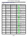
11. List of Diagnostic Trouble Code
A: LIST
S004511A12
Trouble code
11
S004511
Item
Engine speed signal
Content of diagnosis
Detects open or shorted input
signal circuit.
23
Mass air flow signal
(Turbo model)
Detects open or shorted input
signal circuit.
27
ATF temperature sensor
Detects open or shorted input
signal circuit.
31
Throttle position sensor
Detects open or shorted input
signal circuit.
33
Front vehicle speed
sensor
Detects open or shorted input
signal circuit.
36
Torque converter turbine speed sensor
Detects open or shorted input
signal circuit.
38
Torque control signal
Detects open or shorted input
signal circuit.
45
Intake manifold pressure
signal (Non-turbo
model)
Detects open or shorted input
signal circuit.
71
Shift solenoid 1
Detects open or shorted output signal circuit.
72
Shift solenoid 2
Detects open or shorted output signal circuit.
73
Low clutch timing solenoid
Detects open or shorted output signal circuit.
74
2-4 brake timing solenoid
Detects open or shorted output signal circuit.
75
Line pressure duty
solenoid
Detects open or shorted output signal circuit.
76
2-4 brake duty solenoid
Detects open or shorted output signal circuit.
77
Lock-up duty solenoid
Detects open or shorted output signal circuit.
79
Transfer duty solenoid
Detects open or shorted output signal circuit.
93
Rear vehicle speed
sensor
Detects open or shorted input
signal circuit.
AT-27
Index
<Ref. to AT-42, TROUBLE CODE 11 — ENGINE
SPEED SIGNAL —, Diagnostic Procedure with
Trouble Code.>
<Ref. to AT-44, TROUBLE CODE 23 — MASS
AIR FLOW SIGNAL —, Diagnostic Procedure
with Trouble Code.>
<Ref. to AT-46, TROUBLE CODE 27 — ATF
TEMPERATURE SENSOR —, Diagnostic Procedure with Trouble Code.>
<Ref. to AT-50, TROUBLE CODE 31 —
THROTTLE POSITION SENSOR —, Diagnostic
Procedure with Trouble Code.>
<Ref. to AT-58, TROUBLE CODE 33 — FRONT
VEHICLE SPEED SENSOR —, Diagnostic Procedure with Trouble Code.>
<Ref. to AT-64, TROUBLE CODE 36 —
TORQUE CONVERTER TURBINE SPEED SENSOR —, Diagnostic Procedure with Trouble
Code.>
<Ref. to AT-68, TROUBLE CODE 38 —
TORQUE CONTROL SIGNAL —, Diagnostic
Procedure with Trouble Code.>
<Ref. to AT-70, TROUBLE CODE 45 — INTAKE
MANIFOLD PRESSURE SIGNAL —, Diagnostic
Procedure with Trouble Code.>
<Ref. to AT-72, TROUBLE CODE 71 — SHIFT
SOLENOID 1 —, Diagnostic Procedure with
Trouble Code.>
<Ref. to AT-76, TROUBLE CODE 72 — SHIFT
SOLENOID 2 —, Diagnostic Procedure with
Trouble Code.>
<Ref. to AT-80, TROUBLE CODE 73 — LOW
CLUTCH TIMING SOLENOID —, Diagnostic
Procedure with Trouble Code.>
<Ref. to AT-84, TROUBLE CODE 74 — 2-4
BRAKE TIMING SOLENOID —, Diagnostic Procedure with Trouble Code.>
<Ref. to AT-88, TROUBLE CODE 75 — LINE
PRESSURE DUTY SOLENOID —, Diagnostic
Procedure with Trouble Code.>
<Ref. to AT-92, TROUBLE CODE 76 — 2-4
BRAKE DUTY SOLENOID —, Diagnostic Procedure with Trouble Code.>
<Ref. to AT-96, TROUBLE CODE 77 —
LOCK-UP DUTY SOLENOID —, Diagnostic Procedure with Trouble Code.>
<Ref. to AT-100, TROUBLE CODE 79 —
TRANSFER DUTY SOLENOID —, Diagnostic
Procedure with Trouble Code.>
<Ref. to AT-104, TROUBLE CODE 93 — REAR
VEHICLE SPEED SENSOR —, Diagnostic Procedure with Trouble Code.>
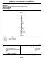
DIAGNOSTIC PROCEDURE FOR POWER INDICATOR LIGHT
Automatic Transmission (Diagnostics)
12. Diagnostic Procedure for Power Indicator Light
S004730
A: POWER INDICATOR LIGHT DOES NOT COME ON OR GO OFF
S004730G75
DIAGNOSIS:
The POWER Indicator light circuit is open or shorted.
TROUBLE SYMPTOM:
쐌 When ignition switch is turned to ON (engine OFF), POWER indicator light does not illuminate.
쐌 When on-board diagnostics is performed, POWER indicator light remains illuminated.
AT-28
DIAGNOSTIC PROCEDURE FOR POWER INDICATOR LIGHT
Automatic Transmission (Diagnostics)
WIRING DIAGRAM:
S3M0621
No.
1
Step
CHECK POWER INDICATOR LIGHT.
Turn ignition switch to ON (engine OFF).
Check
Does POWER indicator
light illuminate?
AT-29
Yes
Go to step 3.
No
Go to step 2.
DIAGNOSTIC PROCEDURE FOR POWER INDICATOR LIGHT
Automatic Transmission (Diagnostics)
No.
Step
CHECK POWER INDICATOR LIGHT.
1) Turn ignition switch to OFF.
2) Remove combination meter.
3) Remove POWER indicator light bulb from
combination meter.
CHECK POWER INDICATOR LIGHT.
Perform “Read Diagnostic Trouble Code”.
<Ref. to AT-22, WITHOUT SUBARU SELECT
MONITOR OPERATION, Read Diagnostic
Trouble Code.>
Check
Is POWER indicator light
bulb OK?
Yes
Go to step 4.
Does POWER indicator
light blink?
4
CHECK FUSE (No. 5).
Remove fuse (No. 5).
Is the fuse (No. 5) blown
out?
5
CHECK HARNESS CONNECTOR
BETWEEN COMBINATION METER AND
IGNITION RELAY.
1) Turn ignition switch to ON (engine OFF).
2) Measure voltage between combination
meter connector and chassis ground.
Connector & terminal
(i10) No. 2 (+) — Chassis ground (−):
CHECK COMBINATION METER.
Measure voltage between combination meter
connector and chassis ground.
Connector & terminal
(i12) No. 6 (+) — Chassis ground (−):
CHECK OPEN CIRCUIT OF HARNESS.
1) Turn ignition switch to OFF.
2) Disconnect TCM and combination meter
connector.
3) Measure resistance of harness between
combination meter.
Connector & terminal
(B56) No. 11 — (i12) No. 6:
CHECK INPUT SIGNAL FOR TCM.
1) Connect connector to TCM and combination meter.
2) Turn ignition switch to ON (engine OFF).
3) Measure voltage between TCM connector
and chassis ground.
Connector & terminal
(B56) No. 11 (+) — Chassis ground (−):
Is voltage more than 9 V?
A temporary poor Go to step 9.
contact of the
connector or harness may be the
cause. Repair
harness or connector in TCM,
inhibitor switch
and combination
meter.
Replace fuse (No. Go to step 5.
5). If replaced
fuse (No. 5) is
blown out easily,
repair short circuit
in harness
between fuse (No.
5) and combination meter.
Go to step 6.
Repair open or
short circuit in
harness between
combination meter
and battery.
CHECK SUBARU SELECT MONITOR.
Do you have SUBARU
SELECT MONITOR?
2
3
6
7
8
9
Is voltage less than 1 V?
Go to step 7.
Is the resistance less than
1 Ω?
Go to step 8.
Is the voltage less than 1
V?
Even if POWER
indicator lights up,
the circuit has
returned to a normal condition at
this time. A temporary poor contact of the connector or harness
may be the
cause. Repair
harness or connector in TCM.
Go to step 10.
AT-30
No
Replace POWER
indicator light
bulb.
Repair combination meter. <Ref.
to IDI-15, Combination Meter
Assembly.>
Repair open circuit in harness
between TCM and
combination
meter, and poor
contact in coupling connector.
Replace TCM.
<Ref. to AT-48,
Transmission
Control Module
(TCM).>
Go to step 11.
DIAGNOSTIC PROCEDURE FOR POWER INDICATOR LIGHT
Automatic Transmission (Diagnostics)
No.
10
11
Step
CHECK INHIBITOR SWITCH.
1) Connect Subaru Select Monitor to data link
connector.
2) Turn ignition switch to ON.
3) Subaru Select Monitor to ON.
4) Read data of range switch using Subaru
Select Monitor.
쐌 Range switch is indicated in ON ⇔ OFF.
CHECK SHORT CIRCUIT OF HARNESS.
1) Disconnect connector from TCM.
2) Remove combination meter.
3) Disconnect connector from combination
meter.
4) Measure resistance of harness connector
between TCM and chassis ground.
Connector & terminal/specified resistance
(B56) No. 11 (+) — Chassis ground (−):
Check
Yes
Go to step 11.
When each range is
selected, does LED of
Subaru Select Monitor light
up?
Is the resistance less than
1 MΩ?
AT-31
Replace TCM.
<Ref. to AT-48,
Transmission
Control Module
(TCM).>
No
Check inhibitor
switch circuit.
<Ref. to AT-122,
CHECK INHIBITOR SWITCH.,
Diagnostic Procedure for
No-trouble Code.>
Repair short circuit in harness
between combination meter connector and TCM
connector.
DIAGNOSTIC PROCEDURE FOR POWER INDICATOR LIGHT
Automatic Transmission (Diagnostics)
B: CHECK POWER SUPPLY AND GROUND LINE
S004730G86
WIRING DIAGRAM:
WITHOUT OBD MODEL
S3M0623
AT-32
DIAGNOSTIC PROCEDURE FOR POWER INDICATOR LIGHT
Automatic Transmission (Diagnostics)
WITH OBD MODEL
S3M0622
AT-33
DIAGNOSTIC PROCEDURE FOR POWER INDICATOR LIGHT
Automatic Transmission (Diagnostics)
No.
1
2
3
4
5
6
7
8
Step
CHECK IGNITION SWITCH.
Check
Is ignition switch ON?
Yes
Go to step 2.
CHECK GENERATOR.
1) Start the engine.
2) Idle the engine.
3) Measure voltage between generator and
chassis ground.
Terminal
Generator B terminal (+) — Chassis
ground (−):
CHECK BATTERY TERMINAL.
Turn ignition switch to OFF.
CHECK POWER SUPPLY OF TCM.
1) Disconnect connector from TCM.
2) Turn ignition switch to ON.
3) Measure voltage between TCM connector
and chassis ground.
Connector & terminal
(B56) No. 1 (+) — Chassis ground (−):
CHECK FUSE (NO. 4).
Remove fuse (No. 4).
Is the voltage between 10
and 15 V?
Go to step 3.
Is there poor contact at
battery terminal?
Is the voltage between 10
and 15 V?
Repair battery
terminal.
Go to step 6.
No
Turn ignition
switch ON.
Repair generator.
<Ref. to SC-12,
Generator.>
Go to step 4.
Go to step 5.
Replace fuse (No.
4). If replaced
fuse (No. 4) has
blown out easily,
repair short circuit
in harness
between fuse (No.
4) and TCM.
Is the voltage more than 10 Go to step 8.
V?
Repair open circuit in harness
between fuse (No.
4) and TCM, or
fuse (No. 4) and
battery, and poor
contact in coupling connector.
Go to step 7.
Replace fuse (No.
11). If replaced
fuse (No. 11) has
blown out easily,
repair short circuit
in harness
between fuse (No.
11) and TCM.
Go to step 9.
Repair open circuit in harness
between fuse (No.
11) and TCM, or
fuse (No. 11) and
battery, and poor
contact in coupling connector.
Repair open circuit in harness
between TCM and
transmission harness connector,
and poor contact
in coupling connector.
Is the fuse (No. 4) blown
out?
CHECK IGNITION POWER SUPPLY CIRCUIT.
1) Turn ignition switch to ON (engine OFF).
2) Measure ignition power supply voltage
between TCM connector and chassis ground.
Connector & terminal
(B54) No. 23 (+) — Chassis ground (–):
(B54) No. 24 (+) — Chassis ground (–):
CHECK FUSE (NO. 11).
Is the fuse (No. 11) blown
Remove fuse (No. 11).
out?
Is the resistance less than
CHECK HARNESS CONNECTOR
1 Ω?
BETWEEN TCM AND TRANSMISSION.
1) Turn ignition switch to OFF.
2) Disconnect connector from TCM and transmission.
3) Measure resistance of harness between
TCM and transmission connector.
Connector & terminal
(B56) No. 19 — (B11) No. 16
(B54) No. 21 — (B11) No. 16
AT-34
DIAGNOSTIC PROCEDURE FOR POWER INDICATOR LIGHT
Automatic Transmission (Diagnostics)
No.
9
10
Step
CHECK HARNESS CONNECTOR
BETWEEN TRANSMISSION AND TRANSMISSION GROUND.
Measure resistance of harness between
transmission and transmission ground.
Connector & terminal
(T4) No. 16 — Transmission ground:
CHECK POOR CONTACT IN CONNECTORS.
Check
Is the resistance less than
1 Ω?
Yes
Go to step 10.
No
Repair open circuit in harness
between transmission and transmission ground.
Is there poor contact in
control module power supply and ground line?
Repair connector.
Replace TCM.
<Ref. to AT-48,
Transmission
Control Module
(TCM).>
AT-35
DIAGNOSTIC PROCEDURE FOR SELECT MONITOR COMMUNICATION
Automatic Transmission (Diagnostics)
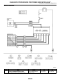
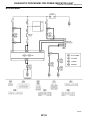
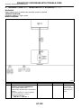
13. Diagnostic Procedure for Select Monitor Communication
A: COMMUNICATION FOR INITIALIZING IMPOSSIBLE
DIAGNOSIS:
쐌 Faulty harness connector
TROUBLE SYMPTOM:
쐌 Select monitor communication failure
AT-36
S004782E34
S004782
DIAGNOSTIC PROCEDURE FOR SELECT MONITOR COMMUNICATION
Automatic Transmission (Diagnostics)
WIRING DIAGRAM:
WITHOUT OBD
S3M0623
AT-37
DIAGNOSTIC PROCEDURE FOR SELECT MONITOR COMMUNICATION
Automatic Transmission (Diagnostics)
WITH OBD
S3M0622
AT-38
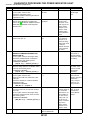
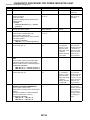
DIAGNOSTIC PROCEDURE FOR SELECT MONITOR COMMUNICATION
Automatic Transmission (Diagnostics)
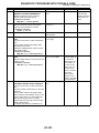
No.
1
2
3
4
5
6
7
8
Step
CHECK THE VEHICLE.
CHECK MAIN RELAY.
1) Turn ignition switch to OFF.
2) Remove main relay.
3) Connect battery to main relay terminals No.
2 (+) and No. 1 (−).
4) Measure resistance between main relay
terminal.
Terminal
No. 4 — No. 6
CHECK GROUND CIRCUIT OF ECM.
<Ref. to AT-50, TROUBLE CODE 31 —
THROTTLE POSITION SENSOR —, Diagnostic Procedure with Trouble Code.>
CHECK HARNESS BETWEEN ECM AND
MAIN RELAY.
1) Remove main relay connector.
2) Measure voltage between main relay and
chassis ground.
Connector & terminal
(B47) No. 1 — Chassis ground:
CHECK INPUT VOLTAGE TO ECM.
1) Install main relay.
2) Disconnect ECM connector.
3) Measure voltage between ECM connector
and chassis ground.
Connector & terminal
(B84) No. 5 (+) — Chassis ground (−):
CHECK INPUT VOLTAGE TO SUBARU
SELECT MONITOR.
1) Connect main relay connector.
2) Turn ignition switch to ON.
3) Measure voltage between data link connector and chassis ground.
Connector & terminal
(B40) No. 1 (+) — Chassis ground (−):
CHECK SUBARU SELECT MONITOR
GROUND CIRCUIT.
1) Turn ignition switch to OFF.
2) Disconnect ECM connector.
3) Measure resistance between data link connector and chassis ground.
Connector & terminal
(B40) No. 12 — Chassis ground:
(B40) No. 13 — Chassis ground:
CHECK HARNESS BETWEEN BATTERY
AND MAIN RELAY.
1) Connect ECM connector.
2) Measure resistance of harness between
data link connector and chassis ground.
Connector & terminal
(B40) No. 12 — Chassis ground:
(B40) No. 13 — Chassis ground:
Check
Yes
Is the target vehicle without Go to step 2.
OBD?
Is the resistance less than Go to step 3.
10 Ω?
No
Go to step 10.
Is there any trouble?
Repair ground
terminal and/or
ground circuit of
ECM.
Is the voltage more than 10 Go to step 5.
V?
Go to step 4.
Is the voltage more than 10 Go to step 6.
V?
Repair open or
short circuit in
harness between
ECM and main
relay connector,
then replace
ECM.
Repair harness
and connector
between data link
connector and
battery.
Is the voltage more than 10 Go to step 7.
V?
Replace main
relay.
Repair short circuit in harness
between battery
and main relay
connector.
Is the resistance more than Go to step 8.
1 MΩ?
Repair harness
and connector
between data link
connector and
ECM connector.
Is the resistance less than
1 Ω?
Replace ECM.
AT-39
Go to step 9.
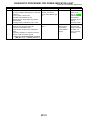
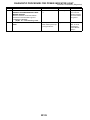
DIAGNOSTIC PROCEDURE FOR SELECT MONITOR COMMUNICATION
Automatic Transmission (Diagnostics)
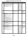
No.
Step
CHECK SUBARU SELECT MONITOR
GROUND CIRCUIT.
Measure resistance between data link connector and ECM connector.
Connector & terminal
(B40) No. 12 — (B84) No. 15:
(B40) No. 13 — (B84) No. 15:
CHECK SUBARU SELECT MONITOR
POWER SUPPLY CIRCUIT.
Measure voltage between data link connector
and chassis ground.
Connector & terminal
(B40) No. 1 — Chassis ground:
Check
Is the resistance less than
1 Ω?
11
CHECK SUBARU SELECT MONITOR
GROUND CIRCUIT.
Measure resistance of harness between data
link connector and chassis ground.
Connector & terminal
(B40) No. 12 — Chassis ground:
(B40) No. 13 — Chassis ground:
Is the resistance less than
1 Ω?
Go to step 12.
12
CHECK COMMUNICATION OF SELECT
MONITOR.
1) Connect ECM connector (Vehicle without
OBD)
2) Turn ignition switch to ON.
3) Using the select monitor, check whether
communication to other systems (such as
engine, ABS etc.) can be executed normally.
CHECK COMMUNICATION OF SELECT
MONITOR.
1) Turn ignition switch to OFF.
2) Disconnect TCM connector.
3) Check whether communication to other
systems (such as ABS etc.) can be executed
normally.
CHECK COMMUNICATION OF SELECT
MONITOR.
1) Turn ignition switch to OFF.
2) Connect TCM connector.
3) Disconnect ECM connector.
4) Check whether communication to other
systems (such as ABS etc.) can be executed
normally.
CHECK COMMUNICATION OF SELECT
MONITOR.
1) Turn ignition switch to OFF.
2) Connect ECM connector.
3) Disconnect ABSCM&H/U connector.
4) Check whether communication to other
systems (such as engine etc.) can be
executed normally.
Are the name and year of
the system displayed on
the select monitor?
9
10
13
14
15
Yes
Go to step 12.
No
Repair harness
and connector
between data link
connector and
ECM connector,
or replace ECM.
Is the voltage more than 10 Go to step 11.
V?
Go to step 17.
Repair harness
and connector
between battery
and data link
connector, and
poor contact in
coupling connector.
Repair open circuit in harness
between data link
connector and
ground terminal,
and poor contact
in coupling connector.
Go to step 13.
Are the name and year of
the system displayed on
the select monitor?
Go to step 19.
Go to step 14.
Are the name and year of
the system displayed on
the select monitor?
Inspect ECM.
Go to step 15.
Are the name and year of
the system displayed on
the select monitor?
Inspect
ABSCM&H/U.
Go to step 16.
AT-40
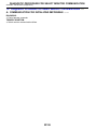
DIAGNOSTIC PROCEDURE FOR SELECT MONITOR COMMUNICATION
Automatic Transmission (Diagnostics)
No.
16
17
18
19
20
21
Step
CHECK COMMUNICATION OF SELECT
MONITOR.
1) Turn ignition switch to OFF.
2) Connect ABSCM&H/U module connector.
3) Disconnect cruise control module connector.
4) Check whether communication to other
systems (such as engine etc.) can be
executed normally.
NOTE:
If the vehicle is not equipped with cruise
control, Go to step 17.
CHECK HARNESS CONNECTOR
BETWEEN EACH CONTROL MODULE AND
DATA LINK CONNECTOR.
1) Turn ignition switch to OFF.
2) Disconnect TCM, ECM, ABSCM&H/U and
cruise control module connectors.
3) Measure resistance between data link connector and chassis ground.
Connector & terminal
(B40) No. 5 — Chassis ground:
(B40) No. 4 — Chassis ground:
CHECK OUTPUT SIGNAL FOR TCM.
1) Turn ignition switch to ON.
2) Measure voltage between data link connector and chassis ground.
Connector & terminal
(B40) No. 5 — Chassis ground:
(B40) No. 4 — Chassis ground:
Check
Are the name and year of
the system displayed on
the select monitor?
CHECK HARNESS/CONNECTOR
BETWEEN TCM AND DATA LINK CONNECTOR.
Measure resistance between TCM connector
and data link connector.
Connector & terminal
(B56) No. 6 — (B40) No. 5:
(B56) No. 15 — (B40) No. 4:
CHECK INSTALLATION OF TCM CONNECTOR.
Turn ignition switch to OFF.
CHECK POOR CONTACT IN CONNECTORS.
Yes
Inspect cruise
control module.
No
Go to step 17.
Is the resistance more than Go to step 18.
1M Ω?
Repair harness
and connector
between each
control module
and data link connector.
Is the voltage more than 1
V?
Repair harness
and connector
between each
control module
and data link connector.
Is the resistance less than
0.5 Ω?
Go to step 20.
A temporary poor
contact of the
connector or harness may be the
cause. Repair
harness or connector in the circuit.
Repair harness
and connector
between TCM and
data link connector.
Is TCM connector inserted
into TCM?
Go to step 21.
Insert TCM connector into TCM.
Is there poor contact in
control module and data
link connector?
Repair poor contact.
Replace TCM.
<Ref. to AT-48,
Transmission
Control Module
(TCM).>
AT-41
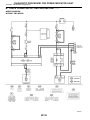
DIAGNOSTIC PROCEDURE WITH TROUBLE CODE
Automatic Transmission (Diagnostics)
14. Diagnostic Procedure with Trouble Code
S004509
A: TROUBLE CODE 11 — ENGINE SPEED SIGNAL —
S004509C39
DIAGNOSIS:
Engine speed input signal circuit is open or shorted.
TROUBLE SYMPTOM:
쐌 No lock-up (after engine warm-up).
쐌 POWER indicator light remains on when vehicle speed is “0”.
WIRING DIAGRAM:
S3M0624
AT-42
DIAGNOSTIC PROCEDURE WITH TROUBLE CODE
Automatic Transmission (Diagnostics)
No.
1
2
3
4
5
6
7
Step
CHECK HARNESS CONNECTOR
BETWEEN TCM AND ECM.
1) Turn ignition switch to OFF.
2) Disconnect connectors from TCM and
ECM.
3) Measure resistance of harness between
TCM and ECM connector.
Connector & terminal
SOHC model:
(B55) No. 17 — (B135) No. 30:
SOHC without OBD:
(B55) No. 17 — (B84) No. 6:
DOHC TURBO:
(B55) No. 17 — (B136) No. 9:
CHECK HARNESS CONNECTOR
BETWEEN TCM AND ECM.
Measure resistance of harness between TCM
connector and chassis ground.
Connector & terminal
(B55) No. 17 — Chassis ground:
PREPARE SUBARU SELECT MONITOR.
Check
Is the resistance less than
1 Ω?
Yes
Go to step 2.
No
Repair open circuit in harness
between TCM and
ECM connector.
Is the resistance more than Go to step 3.
1 MΩ?
Repair short circuit in harness
between TCM and
ECM connector.
Do you have a Subaru
Select Monitor?
Is the voltage more than
10.5 V?
Go to step 4.
Go to step 5.
Even if “POWER” Go to step 6.
indicator lights up,
the circuit has
returned to a normal condition at
this time. A temporary poor contact of the connector or harness
may be the
cause. Repair
harness or connector in the TCM
and ECM.
Even if “POWER” Go to step 6.
Is the revolution value the
CHECK INPUT SIGNAL FOR TCM USING
indicator lights up,
same as the tachometer
SUBARU SELECT MONITOR.
reading shown on the com- the circuit has
1) Connect connectors to TCM and ECM.
returned to a nor2) Connect Subaru Select Monitor to data link bination meter?
mal condition at
connector.
this time. A tem3) Start the engine, and turn Subaru Select
porary poor conMonitor switch to ON.
tact of the con4) Warm-up the engine until engine coolant
nector or harness
temperature is above 80°C (176°F).
may be the
5) Engine idling.
cause. Repair
6) Read data of engine speed using Subaru
harness or conSelect Monitor.
nector in the TCM
쐌 Display shows engine speed signal value
and ECM.
sent from ECM.
Repair poor con- Go to step 7.
CHECK POOR CONTACT.
Is there poor contact in
engine speed signal cirtact.
cuit?
Replace ECM.
Replace TCM.
CONFIRM TROUBLE CODE 11.
Replace ECM with a new
one. Does the trouble code <Ref. to AT-48,
Transmission
appear again, after the
memory has been cleared? Control Module
(TCM).>
CHECK INPUT SIGNAL FOR TCM.
1) Connect connectors to TCM and ECM.
2) Turn ignition switch to ON (engine OFF).
3) Measure voltage between TCM connector
and chassis ground.
Connector & terminal
(B55) No. 17 (+) — Chassis ground (−):
AT-43
DIAGNOSTIC PROCEDURE WITH TROUBLE CODE
Automatic Transmission (Diagnostics)
B: TROUBLE CODE 23 — MASS AIR FLOW SIGNAL —
S004509I01
DIAGNOSIS:
Input signal circuit of TCM from ECM is open or shorted.
TROUBLE SYMPTOM:
Excessive shift shock.
WIRING DIAGRAM:
S3M0625
No.
1
2
3
4
Step
CHECK ENGINE GROUND TERMINALS
AND GROUND CIRCUIT OF ECM
<Ref. to AT-50, TROUBLE CODE 31 THROTTLE POSITION SENSOR -, Diagnostic Procedure with Trouble Code.>
CHECK HARNESS CONNECTOR
BETWEEN TCM AND ECM.
1) Turn ignition switch to OFF.
2) Disconnect connectors from TCM and
ECM.
3) Measure resistance of harness between
TCM and ECM connector.
Connector & terminal
(B54) No. 1 — (B135) No. 28:
CHECK HARNESS CONNECTOR
BETWEEN TCM AND ECM.
Measure resistance of harness between TCM
connector and chassis ground.
Connector & terminal
(B54) No. 1 — Chassis ground:
PREPARE SUBARU SELECT MONITOR.
Check
Is there any trouble?
Yes
Repair ground
terminal and/or
ground circuit of
ECM.
No
Go to step 2.
Is the resistance less than
1 Ω?
Go to step 3.
Repair open circuit in harness
between TCM and
ECM connector.
Is the resistance more than Go to step 4.
1 MΩ?
Repair short circuit in harness
between TCM and
ECM connector.
Do you have a Subaru
Select Monitor?
Go to step 5.
AT-44
Go to step 6.
DIAGNOSTIC PROCEDURE WITH TROUBLE CODE
Automatic Transmission (Diagnostics)
No.
5
6
7
Step
CHECK INPUT SIGNAL FOR TCM.
1) Connect connectors to TCM and ECM.
2) Start the engine, and warm-up the transmission until ATF temperature is above 80°C
(176°F).
NOTE:
If ambient temperature is below 0°C (32°F),
drive the vehicle until the ATF reaches its
operating temperature.
3) Engine idling.
4) Measure voltage between TCM connector
and chassis ground.
Connector & terminal
(B54) No. 1 (+) — Chassis ground (−):
CHECK INPUT SIGNAL FOR TCM USING
SUBARU SELECT MONITOR.
1) Connect connectors to TCM and ECM.
2) Connect Subaru Select Monitor to data link
connector.
3) Start the engine, and turn Subaru Select
monitor switch to ON.
4) Warm-up the engine until engine coolant
temperature is above 80°C (176°F).
5) Engine idling.
6) Read data of intake manifold pressure signal using Subaru Select Monitor.
쐌 Display shows intake manifold pressure
signal value sent from ECM.
CHECK POOR CONTACT.
Check
Is the voltage between 0.4
and 1.8 V?
Is the value between 0.4
and 1.8 V?
Is there poor contact in
intake manifold pressure
signal circuit?
AT-45
Yes
Even if “POWER”
indicator lights up,
the circuit has
returned to a normal condition at
this time. A temporary poor contact of the connector or harness
may be the
cause. Repair
harness or connector in the TCM
and ECM.
Even if “POWER”
indicator lights up,
the circuit has
returned to a normal condition at
this time. A temporary poor contact of the connector or harness
may be the
cause. Repair
harness or connector in the TCM
and ECM.
Repair poor contact.
No
Go to step 7.
Go to step 7.
Replace TCM.
<Ref. to AT-48,
Transmission
Control Module
(TCM).>
DIAGNOSTIC PROCEDURE WITH TROUBLE CODE
Automatic Transmission (Diagnostics)
C: TROUBLE CODE 27 — ATF TEMPERATURE SENSOR —
S004509C76
DIAGNOSIS:
Input signal circuit of TCM to ATF temperature sensor is open or shorted.
TROUBLE SYMPTOM:
Excessive shift shock.
WIRING DIAGRAM:
S3M0626
AT-46
DIAGNOSTIC PROCEDURE WITH TROUBLE CODE
Automatic Transmission (Diagnostics)
No.
1
2
3
4
5
6
7
Step
CHECK HARNESS CONNECTOR
BETWEEN TCM AND ATF TEMPERATURE
SENSOR.
1) Turn ignition switch to OFF.
2) Disconnect connector from transmission
and TCM.
3) Measure resistance of harness between
TCM and transmission connector.
Connector & terminal
(B54) No. 20 — (B11) No. 12:
CHECK HARNESS CONNECTOR
BETWEEN TCM AND ATF TEMPERATURE
SENSOR.
Measure resistance of harness between TCM
and transmission connector.
Connector & terminal
(B54) No. 11 — (B11) No. 11:
CHECK HARNESS CONNECTOR
BETWEEN TCM AND ATF TEMPERATURE
SENSOR.
Measure resistance of harness between TCM
connector and chassis ground.
Connector & terminal
(B54) No. 20 — Chassis ground:
CHECK HARNESS CONNECTOR
BETWEEN TCM AND ATF TEMPERATURE
SENSOR.
Measure resistance of harness between TCM
connector and chassis ground.
Connector & terminal
(B54) No. 11 — Chassis ground:
CHECK ATF TEMPERATURE SENSOR.
1) Turn ignition switch to OFF.
2) Connect connectors to transmission and
TCM.
3) Turn ignition switch to ON and start engine.
4) Warm-up the transmission until ATF temperature reaches to 80°C (176°F).
NOTE:
If ambient temperature is below 0°C (32°F),
drive the vehicle until the ATF reaches its
operating temperature.
5) Disconnect connector from transmission.
6) Measure resistance between transmission
connector terminals.
Connector & terminal
(T4) No. 11 — No. 12:
CHECK ATF TEMPERATURE SENSOR.
1) Turn ignition switch to ON (engine OFF).
2) Measure resistance between transmission
connector terminals.
Connector & terminal
(T4) No. 11 — No. 12:
PREPARE SUBARU SELECT MONITOR.
Check
Is the resistance less than
1 Ω?
Yes
Go to step 2.
No
Repair open circuit in harness
between TCM and
transmission connector.
Is the resistance less than
1 Ω?
Go to step 3.
Repair open circuit in harness
between TCM and
transmission connector.
Is the resistance more than Go to step 4.
1 MΩ?
Repair short circuit in harness
between TCM and
transmission connector.
Is the resistance more than Go to step 5.
1 MΩ?
Repair short circuit in harness
between TCM and
transmission connector.
Is the resistance between
275 and 375 Ω?
Go to step 6.
Go to step 11.
Does the resistance value
increase while the ATF
temperature decreases?
Go to step 7.
Go to step 11.
Do you have a Subaru
Select Monitor?
Go to step 9.
Go to step 8.
AT-47
DIAGNOSTIC PROCEDURE WITH TROUBLE CODE
Automatic Transmission (Diagnostics)
No.
8
Step
CHECK INPUT SIGNAL FOR TCM.
1) Connect connector to transmission.
2) Warm-up the transmission until ATF temperature is about 80°C (176°F).
NOTE:
If ambient temperature is below 0°C (32°F),
drive the vehicle until the ATF reaches its
operating temperature.
3) Measure voltage between TCM connector
terminal.
Connector & terminal
(B54) No. 11 (+) — No. 20 (−):
9
CHECK INPUT SIGNAL FOR TCM USING
SUBARU SELECT MONITOR.
1) Connect connector to transmission.
2) Turn ignition switch to ON (engine OFF).
10
CHECK POOR CONTACT.
11
CHECK HARNESS CONNECTOR
BETWEEN TRANSMISSION AND ATF TEMPERATURE SENSOR.
1) Turn ignition switch to OFF.
2) Disconnect connector from transmission.
3) Remove transmission connector from
bracket.
4) Lift-up the vehicle and place safety stand.
CAUTION:
On AWD models, raise all wheels off
ground.
5) Drain automatic transmission fluid.
CAUTION:
Do not drain the automatic transmission
fluid until it cools down.
6) Remove oil pan, and disconnect connector
from ATF temperature sensor connector.
7) Measure resistance of harness between
ATF temperature sensor and transmission
connector.
Connector & terminal
(T4) No. 11 — (AT1) No. 2:
Check
Is the voltage between 0.4
and 0.9 V?
Yes
Even if “POWER”
indicator lights up,
the circuit has
returned to a normal condition at
this time. Temporary poor contact
of the connector
or harness may
be the case.
Repair harness or
contact in the ATF
temperature sensor and transmission connector.
Does the ATF temperature Even if “POWER”
gradually decrease?
indicator lights up,
the circuit has
returned to a normal condition at
this time. Temporary poor contact
of the connector
or harness may
be the case.
Repair harness or
contact in the ATF
temperature sensor and transmission connector.
Is there poor contact in ATF Repair poor contemperature sensor circuit? tact.
Is the resistance less than
1 Ω?
AT-48
Go to step 12.
No
Go to step 10.
Go to step 10.
Replace TCM.
<Ref. to AT-48,
Transmission
Control Module
(TCM).>
Repair open circuit in harness
between ATF temperature sensor
and transmission
connector.
DIAGNOSTIC PROCEDURE WITH TROUBLE CODE
Automatic Transmission (Diagnostics)
No.
12
13
14
Step
CHECK HARNESS CONNECTOR
BETWEEN TRANSMISSION AND ATF TEMPERATURE SENSOR.
Measure resistance of harness between ATF
temperature sensor and transmission connector.
Connector & terminal
(T4) No. 12 — (AT1) No. 1:
CHECK HARNESS CONNECTOR
BETWEEN TRANSMISSION AND ATF TEMPERATURE SENSOR.
Measure resistance of harness between
transmission connector and transmission
ground.
Connector & terminal
(T4) No. 11 — Transmission ground:
CHECK HARNESS CONNECTOR
BETWEEN TRANSMISSION AND ATF TEMPERATURE SENSOR.
Measure resistance of harness between
transmission connector and transmission
ground.
Connector & terminal
(T4) No. 12 — Transmission ground:
Check
Is the resistance less than
1 Ω?
Yes
Go to step 13.
No
Repair open circuit in harness
between ATF temperature sensor
and transmission
connector.
Is the resistance more than Go to step 14.
1 MΩ?
Repair short circuit in harness
between ATF temperature sensor
and transmission
connector.
Is the resistance more than Replace ATF tem1 MΩ?
perature sensor.
<Ref. to AT-41,
Shift Solenoids,
Duty Solenoids
and ATF Temperature Sensor.>
Repair short circuit in harness
between ATF temperature sensor
and transmission
connector.
AT-49
DIAGNOSTIC PROCEDURE WITH TROUBLE CODE
Automatic Transmission (Diagnostics)
D: TROUBLE CODE 31 — THROTTLE POSITION SENSOR —
S004509C94
DIAGNOSIS:
Input signal circuit of throttle position sensor is open or shorted.
TROUBLE SYMPTOM:
Shift point too high or too low; excessive shift shock; excessive tight corner “braking”.
WIRING DIAGRAM:
SOHC w/o OBD
S3M0627
AT-50
DIAGNOSTIC PROCEDURE WITH TROUBLE CODE
Automatic Transmission (Diagnostics)
SOHC
S3M0628
AT-51
DIAGNOSTIC PROCEDURE WITH TROUBLE CODE
Automatic Transmission (Diagnostics)
DOHC TURBO FOR LHD
S3M0647
AT-52
DIAGNOSTIC PROCEDURE WITH TROUBLE CODE
Automatic Transmission (Diagnostics)
DOHC TURBO FOR RHD
S3M0648
AT-53
DIAGNOSTIC PROCEDURE WITH TROUBLE CODE
Automatic Transmission (Diagnostics)
No.
1
2
3
4
5
Step
CHECK ENGINE GROUND TERMINALS.
CHECK GROUND CIRCUIT OF ECM.
1) Turn ignition switch to OFF.
2) Disconnect connector from ECM.
3) Measure resistance of harness between
ECM and engine ground.
Connector & terminal
SOHC MODEL:
(B134) No. 27 — Engine ground:
(B134) No. 8 — Engine ground:
(B134) No. 7 — Engine ground:
(B136) No. 21 — Engine ground:
(B136) No. 22 — Engine ground:
(B134) No. 35 — Engine ground:
(B134) No. 34 — Engine ground:
(B135) No. 6 — Engine ground:
SOHC w/o OBD MODEL
(E22) No. 10 — Engine ground:
(E22) No. 11— Engine ground:
(E22) No. 12 — Engine ground:
(E22) No. 21 — Engine ground:
DOHC TURBO MODEL:
(B134) No. 7 — Engine ground:
(B134) No. 15 — Engine ground:
(B134) No. 22 — Engine ground:
(B136) No. 8 — Engine ground:
(B136) No. 17 — Engine ground:
(B136) No. 18 — Engine ground:
(B137) No. 8 — Engine ground:
(B137) No. 9 — Engine ground:
CHECK THROTTLE POSITION SENSOR.
1) Disconnect connector from throttle position
sensor.
2) Measure resistance between throttle position sensor connector receptacle’s terminals.
Terminals
SOHC MODEL:
No. 4 — No. 2:
EXCEPT SOHC MODEL:
No. 1 — No. 2:
CHECK THROTTLE POSITION SENSOR.
Measure resistance between throttle position
sensor connector receptacle’s terminals.
Terminals
No. 2 — No. 3:
CHECK HARNESS CONNECTOR
BETWEEN TCM AND THROTTLE POSITION
SENSOR.
1) Disconnect connector from TCM.
2) Measure resistance of harness between
TCM and throttle position sensor connector.
Connector & terminal
(B55) No. 3 — (E13) No. 3:
Check
Have engine ground terminals been tightened?
Is the resistance less than
5 Ω?
Yes
Go to step 2.
Is the resistance between
3.0 and 4.2 kΩ?
Go to step 4.
Replace throttle
position sensor.
Is the resistance between
0.35 and 0.5 kΩ?
Go to step 5.
Replace throttle
position sensor.
Is the resistance less than
1 Ω?
Go to step 6.
Repair open circuit in harness
between TCM and
throttle position
sensor connector,
and poor contact
in coupling connector.
AT-54
Go to step 3.
No
Tighten engine
ground terminals.
Repair open circuit in harness
between ECM
connector and
engine grounding
terminal.
DIAGNOSTIC PROCEDURE WITH TROUBLE CODE
Automatic Transmission (Diagnostics)
No.
6
7
8
9
10
11
12
13
Step
CHECK HARNESS CONNECTOR
BETWEEN TCM AND THROTTLE POSITION
SENSOR.
Measure resistance of harness between TCM
and throttle position sensor connector.
Connector & terminal
(B54) No. 2 — (E13) No. 4:
NOTE:
If SOHC w/o OBD model, Go to step 7.
CHECK HARNESS CONNECTOR
BETWEEN TCM AND THROTTLE POSITION
SENSOR.
Measure resistance of harness between TCM
connector and chassis ground.
Connector & terminal
(B54) No. 3 — Chassis ground:
CHECK HARNESS CONNECTOR
BETWEEN TCM AND THROTTLE POSITION
SENSOR.
Measure resistance of harness between TCM
connector and chassis ground.
Connector & terminal
(B54) No. 2 — Chassis ground:
CHECK HARNESS CONNECTOR
BETWEEN TCM AND ECM.
Measure resistance of harness between TCM
and ECM connector.
Connector & terminal
SOHC w/o OBD MODEL:
(B54) No. 3 — (E22) No. 23:
SOHC MODEL:
(B54) No. 3 — (B136) No. 17:
DOHC TURBO:
(B54) No. 3 — (B135) No. 7:
CHECK HARNESS CONNECTOR
BETWEEN TCM AND ECM.
Measure resistance of harness between TCM
and ECM connector.
Connector & terminal
(B54) No. 2 — (B136) No. 15:
NOTE:
If SOHC w/o OBD model, Go to step 11.
PREPARE SUBARU SELECT MONITOR.
CHECK INPUT SIGNAL FOR TCM.
1) Connect connectors to TCM, throttle position sensor and ECM.
2) Turn ignition switch to ON (engine OFF).
3) Close the throttle completely.
4) Measure voltage between TCM connector
and chassis ground.
Connector & terminal
(B54) No. 3 (+) — Chassis ground (−):
CHECK INPUT SIGNAL FOR TCM.
1) Open the throttle completely.
2) Measure voltage between TCM connector
and chassis ground.
Connector & terminal
(B54) No. 3 (+) — Chassis ground (−):
Check
Is the resistance less than
1 Ω?
Yes
Go to step 7.
No
Repair open circuit in harness
between TCM and
throttle position
sensor connector,
and poor contact
in coupling connector.
Is the resistance more than Go to step 8.
1 MΩ?
Repair short circuit in harness
between TCM and
throttle position
sensor connector.
Is the resistance more than Go to step 9.
1 MΩ?
Repair short circuit in harness
between TCM and
throttle position
sensor connector.
Is the resistance less than
1 Ω?
Go to step 10.
Repair open circuit in harness
between TCM and
ECM connector.
Is the resistance less than
1 Ω?
Go to step 11.
Repair open circuit in harness
between TCM and
ECM connector.
Do you have a Subaru
Select Monitor?
Is the voltage between 0.3
and 0.7 V in throttle fully
closed?
Go to step 14.
Go to step 12.
Go to step 13.
Go to step 18.
Go to step 16.
Go to step 18.
Is the voltage between 4.0
and 4.6 V with throttle fully
open?
AT-55
DIAGNOSTIC PROCEDURE WITH TROUBLE CODE
Automatic Transmission (Diagnostics)
No.
Step
CHECK INPUT SIGNAL FOR TCM USING
SUBARU SELECT MONITOR.
1) Connect connectors to TCM, throttle position sensor and ECM.
2) Connect Subaru Select Monitor to data link
connector.
3) Turn ignition switch to ON (engine OFF).
4) Turn Subaru Select Monitor switch to ON.
5) Throttle fully closed.
6) Read data of throttle position sensor using
Subaru Select Monitor.
쐌 Throttle position sensor input signal is indicated.
CHECK INPUT SIGNAL FOR TCM USING
SUBARU SELECT MONITOR.
Throttle fully open.
NOTE:
Must be changed correspondingly with accelerator pedal operation (from “released” to
“depressed” position).
CHECK INPUT SIGNAL FOR TCM
(THROTTLE POSITION SENSOR POWER
SUPPLY).
Measure voltage between TCM connector and
chassis ground.
Connector & terminal
(B54) No. 2 (+) — Chassis ground (−):
Check
Is the value voltage
between 0.3 and 0.7 V?
Yes
Go to step 15.
No
Go to step 18.
Is the value voltage
between 4.0 and 4.6 V?
Go to step 17.
Go to step 18.
Is the voltage between 4.8
and 5.3 V?
Go to step 18.
17
CHECK INPUT SIGNAL FOR TCM USING
SUBARU SELECT MONITOR (THROTTLE
POSITION SENSOR POWER SUPPLY).
Read data of throttle position sensor power
supply using Subaru Select Monitor.
쐌 Throttle position sensor power supply voltage is indicated.
Is the value voltage
between 4.8 and 5.3 V?
18
CHECK POOR CONTACT.
Is there poor contact in
throttle position sensor circuit?
Even if “POWER”
indicator lights up,
the circuit has
returned to a normal condition at
this time. A temporary poor contact of the connector or harness
may be the
cause. Repair
harness or connector in throttle
position sensor
circuit.
Even if “POWER”
indicator lights up,
the circuit has
returned to a normal condition at
this time. A temporary poor contact of the connector or harness
may be the
cause. Repair
harness or connector in throttle
position sensor
circuit.
Repair poor contact.
14
15
16
AT-56
Go to step 18.
Replace TCM.
<Ref. to AT-48,
Transmission
Control Module
(TCM).>
DIAGNOSTIC PROCEDURE WITH TROUBLE CODE
Automatic Transmission (Diagnostics)
MEMO:
AT-57
DIAGNOSTIC PROCEDURE WITH TROUBLE CODE
Automatic Transmission (Diagnostics)
E: TROUBLE CODE 33 — FRONT VEHICLE SPEED SENSOR —
DIAGNOSIS:
쐌 The vehicle speed signal is abnormal.
쐌 The circuit in combination meter is faulty.
쐌 The harness connector between TCM and vehicle speed sensor is in short or open.
TROUBLE SYMPTOM:
쐌 Erroneous idling.
쐌 Engine stalls.
쐌 Poor driving performance.
AT-58
S004509F60
DIAGNOSTIC PROCEDURE WITH TROUBLE CODE
Automatic Transmission (Diagnostics)
WIRING DIAGRAM:
S3M0629
AT-59
DIAGNOSTIC PROCEDURE WITH TROUBLE CODE
Automatic Transmission (Diagnostics)
No.
1
2
3
Step
CHECK HARNESS CONNECTOR
BETWEEN TCM AND TRANSMISSION.
1) Turn ignition switch to OFF.
2) Disconnect connector from TCM and transmission.
3) Measure resistance of harness between
TCM and transmission connector.
Connector & terminal
(B55) No. 18 — (B11) No. 17:
CHECK HARNESS CONNECTOR
BETWEEN TCM AND TRANSMISSION.
Measure resistance of harness between TCM
and transmission connector.
Connector & terminal
(B54) No. 10 — (B11) No. 18:
Check
Is the resistance less than
1 Ω?
Yes
Go to step 2.
No
Repair open circuit in harness
between TCM and
transmission connector.
Is the resistance less than
1 Ω?
Go to step 3.
CHECK HARNESS CONNECTOR
BETWEEN TCM AND TRANSMISSION.
Measure resistance of harness between TCM
and transmission connector.
Connector & terminal
(B54) No. 10 — Chassis ground:
CHECK HARNESS CONNECTOR
BETWEEN TCM AND TRANSMISSION.
Measure resistance of harness between TCM
and transmission connector.
Connector & terminal
(B55) No. 18 — Chassis ground:
Is the resistance more than Go to step 4.
1 MΩ?
Repair open circuit in harness
between TCM and
transmission
connector, and
poor contact in
coupling connector.
Repair short circuit in harness
between TCM and
transmission connector.
5
CHECK FRONT VEHICLE SPEED SENSOR. Is the resistance between
450 and 650 Ω?
Measure resistance between transmission
connector receptacle’s terminals.
Connector & terminal
(T4) No. 17 — No. 18:
Go to step 6.
6
PREPARE OSCILLOSCOPE.
Do you have oscilloscope?
Go to step 9.
Repair short circuit in harness
between TCM and
transmission
connector, and
poor contact in
coupling connector.
Replace front
vehicle speed
sensor. <Ref. to
AT-32, Front
Vehicle Speed
Sensor.>
Go to step 7.
7
PREPARE SUBARU SELECT MONITOR.
Do you have a Subaru
Select Monitor?
Go to step 10.
Go to step 8.
4
Is the resistance more than Go to step 5.
1 MΩ?
AT-60
DIAGNOSTIC PROCEDURE WITH TROUBLE CODE
Automatic Transmission (Diagnostics)
No.
8
9
Step
CHECK INPUT SIGNAL FOR TCM.
1) Connect all connectors.
2) Lift-up or raise the vehicle and place safety
stands.
CAUTION:
On AWD models, raise all wheels off floor.
3) Start the engine and set vehicle in 20 km/h
(12 MPH) condition.
NOTE:
The speed difference between front and rear
wheels may light the ABS warning light, but
this indicates no malfunction. When AT control
diagnosis is finished, perform the ABS
memory clearance procedure of on-board
diagnostics system. <Ref. to ABS-22, Clear
Memory Mode.>
4) Measure voltage between TCM connector
terminals.
Connector & terminal
(B55) No. 18 (+) — (B54) No. 10 (−):
CHECK FRONT VEHICLE SPEED SENSOR
USING OSCILLOSCOPE.
1) Connect all connectors.
2) Lift-up the vehicle and place safety stand.
CAUTION:
On AWD models, raise all wheels off
ground.
3) Set oscilloscope to TCM connector terminals.
Positive probe; (B55) No. 18
Earth lead; (B54) No. 10
4) Start the engine, and drive the wheels
slowly.
NOTE:
The speed difference between front and rear
wheels may light the ABS warning light, but
this indicates no malfunctions. When AT control diagnosis is finished, perform the ABS
memory clearance procedure of self-diagnosis
system. <Ref. to ABS-22, Clear Memory
Mode.>
5) Measure signal voltage indicated on oscilloscope.
Check
Is the voltage more than
AC 1 V?
Yes
No
Even if “POWER” Go to step 11.
indicator lights up,
the circuit has
returned to a normal condition at
this time. A temporary poor connector or harness
may be the case.
Repair harness or
connector in the
front vehicle
speed sensor circuit.
Is the voltage more than
AC 4 V?
Even if “POWER” Go to step 11.
indicator lights up,
the circuit has
returned to a normal condition at
this time. A temporary poor connector or harness
may be the case.
Repair harness or
connector in the
front vehicle
speed sensor circuit.
AT-61
DIAGNOSTIC PROCEDURE WITH TROUBLE CODE
Automatic Transmission (Diagnostics)
No.
10
11
Step
CHECK INPUT SIGNAL FOR TCM USING
SUBARU SELECT MONITOR.
1) Connect all connectors.
2) Connect Subaru Select Monitor to data link
connector.
3) Lift-up or raise the vehicle and place safety
stands.
CAUTION:
On AWD models, raise all wheels off floor.
4) Turn ignition switch to ON and turn Subaru
Select Monitor switch to ON.
5) Start the engine.
6) Read data of vehicle speed using Subaru
Select Monitor.
쐌 Compare speedometer with Subaru Select
Monitor indications.
쐌 Vehicle speed is indicated in “km/h” or
“MPH”.
7) Slowly increase vehicle speed to 60 km/h
or 37 MPH.
NOTE:
The speed difference between front and rear
wheels may light the ABS warning light, but
this indicates no malfunction. When AT control
diagnosis is finished, perform the ABS
memory clearance procedure of on-board
diagnostics system. <Ref. to ABS-22, Clear
Memory Mode.>
CHECK POOR CONTACT.
Check
Does the speedometer indication increase as the
Subaru Select Monitor data
increases?
Yes
No
Even if “POWER” Go to step 11.
indicator lights up,
the circuit has
returned to a normal condition at
this time. A temporary poor connector or harness
may be the case.
Repair harness or
connector in the
front vehicle
speed sensor circuit.
Is there poor contact in
front vehicle speed sensor
circuit?
Repair poor contact.
AT-62
Replace TCM.
<Ref. to AT-48,
Transmission
Control Module
(TCM).>
DIAGNOSTIC PROCEDURE WITH TROUBLE CODE
Automatic Transmission (Diagnostics)
MEMO:
AT-63
DIAGNOSTIC PROCEDURE WITH TROUBLE CODE
Automatic Transmission (Diagnostics)
F: TROUBLE CODE 36 — TORQUE CONVERTER TURBINE SPEED SENSOR
—
S004509D17
DIAGNOSIS:
Input signal circuit of TCM is open or shorted.
TROUBLE SYMPTOM:
Excessive shift shock.
WIRING DIAGRAM:
S3M0630
AT-64
DIAGNOSTIC PROCEDURE WITH TROUBLE CODE
Automatic Transmission (Diagnostics)
No.
Step
CHECK TORQUE CONVERTER TURBINE
SPEED SENSOR.
1) Turn ignition switch to OFF.
2) Disconnect connector from transmission.
3) Measure resistance between transmission
connector receptacle’s terminals.
Connector & terminal
(T4) No. 14 — No. 15:
CHECK HARNESS CONNECTOR
BETWEEN TCM AND TRANSMISSION.
1) Disconnect connector from TCM.
2) Measure resistance of harness between
TCM and transmission connector.
Connector & terminal
(B55) No. 8 — (B11) No. 14:
CHECK HARNESS CONNECTOR
BETWEEN TCM AND TRANSMISSION.
Measure resistance of harness between TCM
and transmission connector.
Connector & terminal
(B55) No. 9 — (B11) No. 15:
Check
Is the resistance between
450 and 650 Ω?
Yes
Go to step 2.
No
Replace turbine
speed sensor.
<Ref. to AT-37,
Torque Converter
Turbine Speed
Sensor.>
Is the resistance less than
1 Ω?
Go to step 3.
Repair open circuit in harness
between TCM and
transmission connector.
Is the resistance less than
1 Ω?
Go to step 4.
CHECK HARNESS CONNECTOR
BETWEEN TCM AND TRANSMISSION.
Measure resistance of harness between TCM
and chassis ground.
Connector & terminal
(B55) No. 9 — Chassis ground:
CHECK HARNESS CONNECTOR
BETWEEN TCM AND TRANSMISSION.
Measure resistance of harness between TCM
and chassis ground.
Connector & terminal
(B55) No. 8 — Chassis ground:
Is the resistance more than Go to step 5.
1 MΩ?
Repair open circuit in harness
between TCM and
transmission
connector, and
poor contact in
coupling connector.
Repair short circuit in harness
between TCM and
transmission connector.
6
PREPARE OSCILLOSCOPE.
Do you have oscilloscope?
Go to step 10.
Repair short circuit in harness
between TCM and
transmission
connector, and
poor contact in
coupling connector.
Go to step 7.
7
PREPARE SUBARU SELECT MONITOR.
Go to step 9.
Go to step 8.
8
CHECK INPUT SIGNAL FOR TCM.
1) Connect connectors to TCM and transmission.
2) Start the engine and move select lever to
“P” or “N” range.
3) Measure voltage between TCM connector
terminals.
Connector & terminal
(B55) No. 8 (+) — No. 9 (−):
Do you have a Subaru
Select Monitor?
Is the voltage more than
AC 1 V?
1
2
3
4
5
Is the resistance more than Go to step 6.
1 MΩ?
AT-65
Even if “POWER” Go to step 11.
indicator lights up,
the circuit has
returned to a normal condition at
this time. A temporary poor contact of the connector or harness
may be the
cause. Repair
harness or connector in the TCM
and transmission.
DIAGNOSTIC PROCEDURE WITH TROUBLE CODE
Automatic Transmission (Diagnostics)
No.
9
10
11
Step
CHECK INPUT SIGNAL FOR TCM USING
SUBARU SELECT MONITOR.
1) Connect connectors to TCM and transmission.
2) Connect Subaru Select Monitor to data link
connector.
3) Turn ignition switch to ON and turn Subaru
Select Monitor switch to ON.
4) Start the engine.
5) Move select lever to “P” or “N” range.
6) Read data of turbine speed using Subaru
Select Monitor.
쐌 Compare tachometer with Subaru Select
Monitor indications.
CHECK INPUT SIGNAL FOR TCM USING
OSCILLOSCOPE.
1) Connect connectors to TCM and transmission.
2) Set oscilloscope to TCM connector terminals.
Positive probe; (B55) No. 8
Earth lead; (B55) No. 9
3) Start the engine and move select lever to
“P” or “N” range.
Check
Is the revolution value
same as the tachometer
reading shown on the combination meter?
CHECK POOR CONTACT.
Is there poor contact in
torque converter turbine
speed sensor circuit?
Is the signal voltage more
than AC 1 V?
AT-66
Yes
Even if “POWER”
indicator lights up,
the circuit has
returned to a normal condition at
this time. A temporary poor contact of the connector or harness
may be the
cause. Repair
harness or connector in the TCM
and transmission.
Even if “POWER”
indicator lights up,
the circuit has
returned to a normal condition at
this time. A temporary poor contact of the connector or harness
may be the
cause. Repair
harness or connector in the TCM
and transmission.
Repair poor contact.
No
Go to step 11.
Go to step 11.
Replace TCM.
<Ref. to AT-48,
Transmission
Control Module
(TCM).>
DIAGNOSTIC PROCEDURE WITH TROUBLE CODE
Automatic Transmission (Diagnostics)
MEMO:
AT-67
DIAGNOSTIC PROCEDURE WITH TROUBLE CODE
Automatic Transmission (Diagnostics)
G: TROUBLE CODE 38 — TORQUE CONTROL SIGNAL —
S004509D26
DIAGNOSIS:
쐌 The signal circuit is open or shorted.
TROUBLE SYMPTOM:
Excessive shift shock.
WIRING DIAGRAM:
S3M0631
No.
1
2
Step
CHECK HARNESS CONNECTOR
BETWEEN TCM AND ECM.
1) Turn ignition switch to OFF.
2) Disconnect connectors from TCM and
ECM.
3) Measure resistance of harness between
TCM and ECM connector.
Connector & terminal
SOHC without OBD:
(B56) No. 14 — (B84) No. 7:
(B56) No. 5 — (B84) No. 18:
SOHC:
(B56) No. 14 — (B135) No. 17:
(B56) No. 5 — (B135) No. 16:
DOHC TURBO:
(B56) No. 14 — (B134) No. 18:
(B56) No. 5 — (B134) No. 19:
CHECK HARNESS CONNECTOR
BETWEEN TCM AND ECM.
Measure resistance of harness between TCM
connector and chassis ground.
Connector & terminal
(B56) No. 14 — Chassis ground:
(B56) No. 5 — Chassis ground:
Check
Is the resistance less than
1 Ω?
Yes
Go to step 2.
No
Repair open circuit in harness
between TCM and
ECM connector.
Is the resistance more than Go to step 3.
1 MΩ?
Repair short circuit in harness
between TCM and
ECM connector.
AT-68
DIAGNOSTIC PROCEDURE WITH TROUBLE CODE
Automatic Transmission (Diagnostics)
No.
3
Step
Check
CHECK OUTPUT SIGNAL EMITTED FROM Is the voltage more than
4.8 V?
TCM.
1) Connect connectors to TCM and ECM.
2) Turn ignition switch to ON (engine OFF).
3) Measure voltage between TCM connector
terminals.
Connector & terminal
(B56) No. 14 (+) — Chassis ground (−):
(B56) No. 5 (+) — Chassis ground (−):
4
CHECK POOR CONTACT.
5
CHECK GROUND LINE BETWEEN TRANSMISSION AND BODY.
Check installing condition of ground line in
transmission and body.
CHECK GROUND LINE BETWEEN TRANSMISSION AND BODY.
Check installing condition of ground line in
transmission and body.
Tightening torque:
13±3 N·m (1.3±0.3 kgf-m, 9.4±2.2 ft-lb)
CHECK GROUND LINE INSIDE TRANSMISSION.
1) Drain AT fluid and remove oil pan.
2) Check tightening torque value of ground
line installing bolt.
Tightening torque:
T: 8±1 N·m (0.8±0.1 kgf-m, 5.8±0.7 ft-lb)
CHECK GROUND CIRCUIT OF ECM.
<Ref. to AT-50, TROUBLE CODE 31 THROTTLE POSITION SENSOR -, Diagnostic Procedure with Trouble Code.>
RECHECK OUTPUT SIGNAL EMITTED
FROM TCM.
Measure voltage between TCM connector and
chassis ground.
Connector & terminal
(B56) No. 14 (+) — Chassis ground (−):
(B56) No. 5 (+) — Chassis ground (−):
6
7
8
9
Yes
No
Even if “POWER” Go to step 4.
indicator lights up,
the circuit has
returned to a normal condition at
this time. A temporary poor contact of the connector or harness
may be the
cause. Repair
harness or connector in the TCM
and ECM.
Repair poor con- Go to step 5.
tact.
Is there poor contact in
torque control signal circuit?
Is there any dirt or rust at
Remove dirt and
ground line installing point? rust.
Go to step 6.
Is tightening torque value
within specification?
Go to step 7.
Tighten to specified torque.
Is tightening torque value
within specification?
Go to step 9.
Tighten to specified torque.
Is there any trouble?
Repair ground
terminal and/or
ground circuit of
ECM.
Replace TCM.
<Ref. to AT-48,
Transmission
Control Module
(TCM).>
Go to step 9.
Is each voltage more than
4.8 V?
AT-69
Replace ECM.
DIAGNOSTIC PROCEDURE WITH TROUBLE CODE
Automatic Transmission (Diagnostics)
H: TROUBLE CODE 45 — INTAKE MANIFOLD PRESSURE SIGNAL —
S004509D48
DIAGNOSIS:
Input signal circuit of TCM from ECM is open or shorted.
TROUBLE SYMPTOM:
Excessive shift shock.
WIRING DIAGRAM:
S3M0632
No.
1
2
3
Step
CHECK ENGINE GROUND TERMINALS
AND GROUND CIRCUIT OF ECM
<Ref. to AT-50, TROUBLE CODE 31 THROTTLE POSITION SENSOR -, Diagnostic Procedure with Trouble Code.>
CHECK HARNESS CONNECTOR
BETWEEN TCM AND ECM.
1) Turn ignition switch to OFF.
2) Disconnect connectors from TCM and
ECM.
3) Measure resistance of harness between
TCM and ECM connector.
Connector & terminal
SOHC without OBD:
(B54) No. 1 — (B84) No. 29:
SOHC:
(B54) No. 1 — (B136) No. 11:
CHECK HARNESS CONNECTOR
BETWEEN TCM AND ECM.
Measure resistance of harness between TCM
connector and chassis ground.
Connector & terminal
(B54) No. 1 — Chassis ground:
Check
Is there any trouble?
Yes
Repair ground
terminal and/or
ground circuit of
ECM.
No
Go to step 2.
Is the resistance less than
1 Ω?
Go to step 3.
Repair open circuit in harness
between TCM and
ECM connector.
Is the resistance more than Go to step 4.
1 MΩ?
Repair short circuit in harness
between TCM and
ECM connector.
AT-70
DIAGNOSTIC PROCEDURE WITH TROUBLE CODE
Automatic Transmission (Diagnostics)
No.
4
5
6
7
Step
PREPARE SUBARU SELECT MONITOR.
Check
Do you have a Subaru
Select Monitor?
Is the voltage between 0.4
and 1.8 V?
CHECK INPUT SIGNAL FOR TCM.
1) Connect connectors to TCM and ECM.
2) Start the engine, and warm-up the transmission until ATF temperature is above 80°C
(176°F).
NOTE:
If ambient temperature is below 0°C (32°F),
drive the vehicle until the ATF reaches its
operating temperature.
3) Engine idling.
4) Measure voltage between TCM connector
and chassis ground.
Connector & terminal
(B54) No. 1 (+) — Chassis ground (−):
Is the value between 0.4
CHECK INPUT SIGNAL FOR TCM USING
and 1.8 V?
SUBARU SELECT MONITOR.
1) Connect connectors to TCM and ECM.
2) Connect Subaru Select Monitor to data link
connector.
3) Start the engine, and turn Subaru Select
monitor switch to ON.
4) Warm-up the engine until engine coolant
temperature is above 80°C (176°F).
5) Engine idling.
6) Read data of intake manifold pressure signal using Subaru Select Monitor.
쐌 Display shows intake manifold pressure
signal value sent from ECM.
CHECK POOR CONTACT.
Is there poor contact in
intake manifold pressure
signal circuit?
AT-71
Yes
Go to step 6.
No
Go to step 5.
Even if “POWER”
indicator lights up,
the circuit has
returned to a normal condition at
this time. A temporary poor contact of the connector or harness
may be the
cause. Repair
harness or connector in the TCM
and ECM.
Even if “POWER”
indicator lights up,
the circuit has
returned to a normal condition at
this time. A temporary poor contact of the connector or harness
may be the
cause. Repair
harness or connector in the TCM
and ECM.
Repair poor contact.
Go to step 7.
Go to step 7.
Replace TCM.
<Ref. to AT-48,
Transmission
Control Module
(TCM).>
DIAGNOSTIC PROCEDURE WITH TROUBLE CODE
Automatic Transmission (Diagnostics)
I: TROUBLE CODE 71 — SHIFT SOLENOID 1 —
S004509D91
DIAGNOSIS:
Output signal circuit of shift solenoid 1 is open or shorted.
TROUBLE SYMPTOM:
Does not shift.
WIRING DIAGRAM:
TR0410
No.
1
Step
Check
Is the resistance less than
CHECK HARNESS CONNECTOR
1 Ω?
BETWEEN TCM AND TRANSMISSION.
1) Turn ignition switch to OFF.
2) Disconnect connector from TCM and transmission.
3) Measure resistance of harness between
TCM and shift solenoid 1 connector.
Connector & terminal
(B54) No. 22 — (B11) No. 1:
AT-72
Yes
Go to step 2.
No
Repair open circuit in harness
between TCM and
transmission connector.
DIAGNOSTIC PROCEDURE WITH TROUBLE CODE
Automatic Transmission (Diagnostics)
No.
2
3
4
5
Step
CHECK HARNESS CONNECTOR
BETWEEN TCM AND TRANSMISSION.
Measure resistance of harness between TCM
connector and chassis ground.
Connector & terminal
(B54) No. 22 — Chassis ground:
CHECK SHIFT SOLENOID 1.
Measure resistance between transmission
connector terminals.
Connector & terminal
(T4) No. 1 — No. 16:
CHECK OUTPUT SIGNAL EMITTED FROM
TCM.
1) Connect connectors to TCM and transmission.
2) Turn ignition switch to ON (engine OFF).
3) Move select lever to “D” range.
4) Measure voltage between TCM connector
and chassis ground.
Connector & terminal
(B54) No. 22 (+) — Chassis ground (−):
CHECK OUTPUT SIGNAL EMITTED FROM
TCM.
1) Hold switch to ON.
2) Measure voltage between TCM connector
and chassis ground.
Connector & terminal
(B54) No. 22 (+) — Chassis ground (−):
Check
Yes
Is the resistance more than Go to step 3.
1 MΩ?
No
Repair short circuit in harness
between TCM and
transmission connector.
Is the resistance between
10 and 16 Ω?
Go to step 4.
Go to step 7.
Is the voltage more than
9V?
Go to step 5.
Go to step 6.
Is the voltage less than
1V?
Even if “POWER” Go to step 6.
indicator lights up,
the circuit has
returned to a normal condition at
this time. A temporary poor contact of the connector or harness
may be the
cause. Repair
harness or contact in the TCM.
Repair poor con- Replace TCM.
tact.
<Ref. to AT-48,
Transmission
Control Module
(TCM).>
Go to step 8.
Replace shift
solenoid 1. <Ref.
to AT-48, Transmission Control
Module (TCM).>
6
CHECK POOR CONTACT.
Is there poor contact in
shift solenoid 1 circuit?
7
CHECK SHIFT SOLENOID 1 (IN TRANSMIS- Is the resistance between
10 and 16 Ω?
SION).
1) Remove transmission connector from
bracket.
2) Lift-up or raise the vehicle and support with
safety stand.
CAUTION:
On AWD models, raise all wheels off
ground.
3) Drain automatic transmission fluid.
CAUTION:
Do not drain the automatic transmission
fluid until it cools down.
4) Remove oil pan, and disconnect connector
from shift solenoid 1.
5) Measure resistance between shift solenoid
1 connector and transmission ground.
Terminal
No. 1 — Transmission ground:
AT-73
DIAGNOSTIC PROCEDURE WITH TROUBLE CODE
Automatic Transmission (Diagnostics)
No.
8
9
Step
CHECK HARNESS CONNECTOR
BETWEEN SHIFT SOLENOID 1 AND
TRANSMISSION.
Measure resistance of harness between shift
solenoid 1 and transmission connector.
Connector & terminal
(AT5) No. 1 — (T4) No. 1:
CHECK HARNESS CONNECTOR
BETWEEN SHIFT SOLENOID 1 AND
TRANSMISSION.
Measure resistance of harness between shift
solenoid 1 connector and transmission
ground.
Connector & terminal
(T4) No. 1 — Transmission ground:
Check
Is the resistance less than
1 Ω?
Yes
Go to step 9.
Is the resistance more than Even if “POWER”
1 MΩ?
indicator lights up,
the circuit has
returned to a normal condition at
this time. A temporary poor contact of the connector or harness
may be the
cause. Repair
harness or connector in shift
solenoid 1 and
transmission.
AT-74
No
Repair open circuit in harness
between shift
solenoid 1 and
transmission connector.
Repair short circuit harness
between shift
solenoid 1 and
transmission connector.
DIAGNOSTIC PROCEDURE WITH TROUBLE CODE
Automatic Transmission (Diagnostics)
MEMO:
AT-75
DIAGNOSTIC PROCEDURE WITH TROUBLE CODE
Automatic Transmission (Diagnostics)
J: TROUBLE CODE 72 — SHIFT SOLENOID 2 —
S004509D98
DIAGNOSIS:
Output signal circuit of shift solenoid 2 is open or shorted.
TROUBLE SYMPTOM:
Does not shift.
WIRING DIAGRAM:
TR0411
No.
1
Step
Check
Is the resistance less than
CHECK HARNESS CONNECTOR
1 Ω?
BETWEEN TCM AND TRANSMISSION.
1) Turn ignition switch to OFF.
2) Disconnect connector from TCM and transmission.
3) Measure resistance of harness between
TCM and shift solenoid 2 connector.
Connector & terminal
(B54) No. 5 — (B11) No. 2:
AT-76
Yes
Go to step 2.
No
Repair open circuit in harness
between TCM and
transmission connector.
DIAGNOSTIC PROCEDURE WITH TROUBLE CODE
Automatic Transmission (Diagnostics)
No.
2
3
4
5
6
Step
CHECK HARNESS CONNECTOR
BETWEEN TCM AND TRANSMISSION.
Measure resistance of harness between TCM
connector and transmission ground.
Connector & terminal
(B54) No. 5 — Transmission ground:
CHECK SHIFT SOLENOID 2.
Measure resistance between transmission
connector terminals.
Connector & terminal
(T4) No. 2 — No. 16:
CHECK OUTPUT SIGNAL EMITTED FROM
TCM.
1) Connect connectors to TCM and transmission.
2) Lift-up or raise the vehicle and support with
safety stand.
CAUTION:
On AWD models, raise all wheels off
ground.
3) Start the engine and warm-up the transmission until ATF temperature is above 80°C
(176°F).
NOTE:
If ambient temperature is below 0°C (32°F),
drive the vehicle until the ATF reaches its
operating temperature.
4) Move selector lever to “D”, and slowly
increase vehicle speed to 50 km/h (31 MPH).
NOTE:
The speed difference between front and rear
wheels may light the ABS warning light, but
this indicates no malfunction. When AT control
diagnosis is finished, perform the ABS
memory clearance procedure of on-board
diagnostics system. <Ref. to ABS-22, Clear
Memory Mode.>
5) Measure voltage between TCM connector
and chassis ground.
Connector & terminal
(B54) No. 22 (+) — Chassis ground (−):
CHECK POOR CONTACT.
Check
Yes
Is the resistance more than Go to step 3.
1 MΩ?
No
Repair short circuit in harness
between TCM and
transmission connector.
Is the resistance between
10 and 16 Ω?
Go to step 4.
Go to step 6.
Is the voltage less than 1
V?
Even if “POWER” Go to step 5.
indicator lights up,
the circuit has
returned to a normal condition at
this time. A temporary poor contact of the connector or harness
may be the
cause. Repair
harness or connector in the TCM
and transmission.
Is there poor contact in
shift solenoid 2 circuit?
Repair poor contact.
CHECK SHIFT SOLENOID 2 (IN TRANSMIS- Is the resistance between
10 and 16 Ω?
SION).
1) Remove transmission connector from
bracket.
2) Drain automatic transmission fluid.
CAUTION:
Do not drain the automatic transmission
fluid until it cools down.
3) Remove oil pan, and disconnect connector
from shift solenoid 2.
4) Measure resistance between shift solenoid
2 connector and transmission ground.
Connector & terminal
No. 1 — Transmission ground:
AT-77
Go to step 7.
Replace TCM.
<Ref. to AT-48,
Transmission
Control Module
(TCM).>
Replace shift
solenoid 2 assembly. <Ref. to
AT-41, Shift
Solenoids, Duty
Solenoids and
ATF Temperature
Sensor.>
DIAGNOSTIC PROCEDURE WITH TROUBLE CODE
Automatic Transmission (Diagnostics)
No.
7
8
Step
CHECK HARNESS CONNECTOR
BETWEEN SHIFT SOLENOID 2 AND
TRANSMISSION.
Measure resistance of harness between shift
solenoid 2 and transmission connector.
Connector & terminal
(AT6) No. 1 — (T4) No. 2:
CHECK HARNESS CONNECTOR
BETWEEN SHIFT SOLENOID 2 AND
TRANSMISSION.
Measure resistance of harness between shift
solenoid 2 connector and transmission
ground.
Connector & terminal
(T4) No. 2 — Transmission ground:
Check
Is the resistance less than
1 Ω?
Yes
Go to step 8.
Is the resistance more than Even if “POWER”
1 MΩ?
indicator lights up,
the circuit has
returned to a normal condition at
this time. A temporary poor contact of the connector or harness
may be the
cause. Repair
harness or connector in shift
solenoid 2 and
transmission.
AT-78
No
Repair open circuit in harness
between shift
solenoid 2 and
transmission connector.
Repair short circuit harness
between shift
solenoid 2 and
transmission connector.
DIAGNOSTIC PROCEDURE WITH TROUBLE CODE
Automatic Transmission (Diagnostics)
MEMO:
AT-79
DIAGNOSTIC PROCEDURE WITH TROUBLE CODE
Automatic Transmission (Diagnostics)
K: TROUBLE CODE 73 — LOW CLUTCH TIMING SOLENOID —
S004509E05
DIAGNOSIS:
Output signal circuit of low clutch timing solenoid is open or shorted.
TROUBLE SYMPTOM:
Excessive shift shock.
WIRING DIAGRAM:
TR0412
No.
1
Step
Check
Is the resistance less than
CHECK HARNESS CONNECTOR
1 Ω?
BETWEEN TCM AND TRANSMISSION.
1) Turn ignition switch to OFF.
2) Disconnect connector from TCM and transmission.
3) Measure resistance of harness between
TCM and transmission connector.
Connector & terminal
(B54) No. 15 — (B11) No. 3:
AT-80
Yes
Go to step 2.
No
Repair open circuit in harness
between TCM and
transmission connector.
DIAGNOSTIC PROCEDURE WITH TROUBLE CODE
Automatic Transmission (Diagnostics)
No.
2
3
4
5
6
7
Step
CHECK HARNESS CONNECTOR
BETWEEN TCM AND TRANSMISSION.
Measure resistance of harness between TCM
connector and transmission ground.
Connector & terminal
(B54) No. 15 — Chassis ground:
CHECK LOW CLUTCH TIMING SOLENOID.
Measure resistance between transmission
connector terminals.
Connector & terminal
(T4) No. 3 — No. 16:
CHECK OUTPUT SIGNAL EMITTED FROM
TCM.
1) Connect connectors to TCM and transmission.
2) Turn ignition switch to ON (engine OFF).
3) Move select lever to “D” range.
4) Measure voltage between TCM connector
and chassis ground.
Connector & terminal
(B54) No. 15 (+) — Chassis ground (−):
CHECK OUTPUT SIGNAL EMITTED FROM
TCM.
1) Hold switch to ON.
2) Measure voltage between TCM connector
and chassis ground.
Connector & terminal
(B54) No. 15 (+) — Chassis ground (−):
Check
Yes
Is the resistance more than Go to step 3.
1 MΩ?
No
Repair short circuit in harness
between TCM and
transmission connector.
Is the resistance between
10 and 16 Ω?
Go to step 4.
Go to step 7.
Is the voltage more than
9V?
Go to step 5.
Go to step 6.
Even if “POWER” Go to step 6.
indicator lights up,
the circuit has
returned to a normal condition at
this time. A temporary poor contact of the connector or harness
may be the
cause. Repair
harness or contact in the TCM
and transmission.
CHECK POOR CONTACT.
Is there poor contact in low Repair poor con- Replace TCM.
clutch timing solenoid cirtact.
<Ref. to AT-48,
cuit?
Transmission
Control Module
(TCM).>
Go to step 8.
Replace low
CHECK LOW CLUTCH TIMING SOLENOID Is the resistance between
10 and 16 Ω?
clutch timing sole(IN TRANSMISSION).
noid. <Ref. to
1) Remove transmission connector from
AT-41, Shift
bracket.
Solenoids, Duty
2) Lift-up or raise the vehicle and support with
Solenoids and
safety stand.
ATF Temperature
CAUTION:
Sensor.>
On AWD models, raise all wheels off
ground.
3) Drain automatic transmission fluid.
CAUTION:
Do not drain the automatic transmission
fluid until it cools down.
4) Remove oil pan, and disconnect connector
from low clutch timing solenoid.
5) Measure resistance between low clutch
timing solenoid connector and transmission
ground.
Terminal
No. 1 — Transmission ground:
Is the voltage less than
1V?
AT-81
DIAGNOSTIC PROCEDURE WITH TROUBLE CODE
Automatic Transmission (Diagnostics)
No.
8
9
Step
CHECK HARNESS CONNECTOR
BETWEEN LOW CLUTCH TIMING SOLENOID AND TRANSMISSION.
Measure resistance of harness between low
clutch timing solenoid and transmission connector.
Connector & terminal
(AT9) No. 1 — (T4) No. 3:
CHECK HARNESS CONNECTOR
BETWEEN LOW CLUTCH TIMING SOLENOID AND TRANSMISSION.
Measure resistance of harness between low
clutch timing solenoid connector and transmission ground.
Connector & terminal
(T4) No. 3 — Transmission ground:
Check
Is the resistance less than
1 Ω?
Yes
Go to step 9.
Is the resistance more than Even if “POWER”
1 MΩ?
indicator lights up,
the circuit has
returned to a normal condition at
this time. A temporary poor contact of the connector or harness
may be the
cause. Repair
harness or connector in low
clutch timing solenoid and transmission.
AT-82
No
Repair open circuit in harness
between low
clutch timing solenoid and transmission connector.
Repair short circuit harness
between low
clutch timing solenoid and transmission connector.
DIAGNOSTIC PROCEDURE WITH TROUBLE CODE
Automatic Transmission (Diagnostics)
MEMO:
AT-83
DIAGNOSTIC PROCEDURE WITH TROUBLE CODE
Automatic Transmission (Diagnostics)
L: TROUBLE CODE 74 — 2-4 BRAKE TIMING SOLENOID —
S004509E07
DIAGNOSIS:
Output signal circuit of 2-4 brake timing solenoid is open or shorted.
TROUBLE SYMPTOM:
Excessive shift shock.
WIRING DIAGRAM:
TR0413
No.
1
Step
Check
Is the resistance less than
CHECK HARNESS CONNECTOR
1 Ω?
BETWEEN TCM AND TRANSMISSION.
1) Turn ignition switch to OFF.
2) Disconnect connector from TCM and transmission.
3) Measure resistance of harness between
TCM and transmission connector.
Connector & terminal
(B54) No. 16 — (B11) No. 4:
AT-84
Yes
Go to step 2.
No
Repair open circuit in harness
between TCM and
transmission connector.
DIAGNOSTIC PROCEDURE WITH TROUBLE CODE
Automatic Transmission (Diagnostics)
No.
2
3
4
5
Step
CHECK HARNESS CONNECTOR
BETWEEN TCM AND TRANSMISSION.
Measure resistance of harness between TCM
connector and transmission ground.
Connector & terminal
(B54) No. 16 — Chassis ground:
CHECK 2-4 BRAKE TIMING SOLENOID.
Measure resistance between transmission
connector terminals.
Connector & terminal
(T4) No. 4 — No. 16:
CHECK OUTPUT SIGNAL EMITTED FROM
TCM.
1) Connect connectors to TCM and transmission.
2) Lift-up or raise the vehicle and support with
safety stand.
CAUTION:
On AWD models, raise all wheels off
ground.
3) Start the engine and warm-up the transmission until ATF temperature is above 80°C
(176°F).
NOTE:
If ambient temperature is below 0°C (32°F),
drive the vehicle until the ATF reaches its
operating temperature.
4) Move selector lever to “1”, and slowly
increase vehicle speed to 10 km/h (6 MPH).
NOTE:
The speed difference between front and rear
wheels may light the ABS warning light, but
this indicates no malfunction. When AT control
diagnosis is finished, perform the ABS
memory clearance procedure of on-board
diagnostics system. <Ref. to ABS-22, Clear
Memory Mode.>
5) Measure voltage between TCM connector
and chassis ground.
Connector & terminal
(B54) No. 16 (+) — Chassis ground (−):
CHECK OUTPUT SIGNAL EMITTED FROM
TCM.
1) Move selector lever to “D”, and slowly
increase vehicle speed to 65 km/h (40 MPH).
NOTE:
The speed difference between front and rear
wheels may light the ABS warning light, but
this indicates no malfunction. When AT control
diagnosis is finished, perform the ABS
memory clearance procedure of on-board
diagnostics system. <Ref. to ABS-22, Clear
Memory Mode.>
2) Measure voltage between TCM connector
and chassis ground.
Connector & terminal
(B54) No. 16 (+) — Chassis ground (−):
Check
Yes
Is the resistance more than Go to step 3.
1 MΩ?
No
Repair short circuit in harness
between TCM and
transmission connector.
Is the resistance between
10 and 16 Ω?
Go to step 4.
Go to step 7.
Is the voltage less than 1
V?
Go to step 5.
Go to step 6.
Is the voltage more than 9
V?
Even if “POWER” Go to step 6.
indicator lights up,
the circuit has
returned to a normal condition at
this time. A temporary poor contact of the connector or harness
may be the
cause. Repair
harness or contact in the transmission.
AT-85
DIAGNOSTIC PROCEDURE WITH TROUBLE CODE
Automatic Transmission (Diagnostics)
No.
6
7
8
9
Step
CHECK POOR CONTACT.
Check
Yes
Is there poor contact in 2-4 Repair poor contact.
brake timing solenoid circuit?
CHECK 2-4 BRAKE TIMING SOLENOID (IN
TRANSMISSION).
1) Remove transmission connector from
bracket.
2) Lift-up or raise the vehicle and support with
safety stand.
CAUTION:
On AWD models, raise all wheels off
ground.
3) Drain automatic transmission fluid.
CAUTION:
Do not drain the automatic transmission
fluid until it cools down.
4) Remove oil pan, and disconnect connector
from 2-4 brake timing solenoid.
5) Measure resistance between 2-4 brake timing solenoid connector and transmission
ground.
Terminal
No. 1 — Transmission ground:
CHECK HARNESS CONNECTOR
BETWEEN 2-4 BRAKE TIMING SOLENOID
AND TRANSMISSION.
Measure resistance of harness between 2-4
brake timing solenoid and transmission connector.
Connector & terminal
(AT8) No. 1 — (T4) No. 4:
CHECK HARNESS CONNECTOR
BETWEEN 2-4 BRAKE TIMING SOLENOID
AND TRANSMISSION.
Measure resistance of harness between 2-4
brake timing solenoid connector and transmission ground.
Connector & terminal
(T4) No. 4 — Transmission ground:
Is the resistance between
10 and 16 Ω?
Go to step 8.
Is the resistance less than
1 Ω?
Go to step 9.
Is the resistance more than Even if “POWER”
1 MΩ?
indicator lights up,
the circuit has
returned to a normal condition at
this time. A temporary poor contact of the connector or harness
may be the
cause. Repair
harness or connector in 2-4
brake timing solenoid and transmission.
AT-86
No
Replace TCM.
<Ref. to AT-48,
Transmission
Control Module
(TCM).>
Replace 2-4 brake
timing solenoid.
<Ref. to AT-41,
Shift Solenoids,
Duty Solenoids
and ATF Temperature Sensor.>
Repair open circuit in harness
between 2-4
brake timing solenoid and transmission connector.
Repair short circuit harness
between 2-4
brake timing solenoid and transmission connector.
DIAGNOSTIC PROCEDURE WITH TROUBLE CODE
Automatic Transmission (Diagnostics)
MEMO:
AT-87
DIAGNOSTIC PROCEDURE WITH TROUBLE CODE
Automatic Transmission (Diagnostics)
M: TROUBLE CODE 75 — LINE PRESSURE DUTY SOLENOID —
S004509E14
DIAGNOSIS:
Output signal circuit of line pressure duty solenoid is open or shorted.
TROUBLE SYMPTOM:
Excessive shift shock.
WIRING DIAGRAM:
TR0414
No.
1
2
3
4
Step
CHECK HARNESS CONNECTOR
BETWEEN TCM AND TRANSMISSION.
1) Turn ignition switch to OFF.
2) Disconnect connector from transmission
and TCM.
3) Measure resistance of harness between
TCM and transmission connector.
Connector & terminal
(B54) No. 9 — (B11) No. 5:
CHECK HARNESS CONNECTOR
BETWEEN TCM AND CHASSIS GROUND.
Measure resistance of harness between TCM
and chassis ground.
Connector & terminal
(B54) No. 9 — Chassis ground:
CHECK LINE PRESSURE DUTY SOLENOID.
Measure resistance between transmission
connector receptacle’s terminals.
Terminal
(T4) No. 5 — No. 16:
PREPARE SUBARU SELECT MONITOR.
Check
Is the resistance less than
1 Ω?
Yes
Go to step 2.
No
Repair open circuit in harness
between TCM and
transmission connector.
Is the resistance more than Go to step 3.
1 MΩ?
Repair short circuit in harness
between TCM and
transmission connector.
Is the resistance between
2.0 and 4.5 Ω?
Go to step 4.
Go to step 10.
Do you have a Subaru
Select Monitor?
Go to step 7.
Go to step 5.
AT-88
DIAGNOSTIC PROCEDURE WITH TROUBLE CODE
Automatic Transmission (Diagnostics)
No.
5
6
7
Step
CHECK OUTPUT SIGNAL EMITTED FROM
TCM.
1) Connect all connectors.
2) Start the engine and warm-up the transmission until ATF temperature is above 80°C
(176°F).
NOTE:
If ambient temperature is below 0°C (32°F),
drive the vehicle until the ATF reaches its
operating temperature.
3) Turn ignition switch to ON (engine OFF).
4) Move select lever to “N”.
5) Measure voltage between TCM connector
and chassis ground.
Connector & terminal
(B54) No. 9 (+) — Chassis ground (−):
CHECK OUTPUT SIGNAL EMITTED FROM
TCM.
Measure voltage between TCM connector and
chassis ground.
Connector & terminal
(B54) No. 9 (+) — Chassis ground (−):
CHECK OUTPUT SIGNAL EMITTED FROM
TCM USING SUBARU SELECT MONITOR.
1) Connect connectors to TCM and transmission.
2) Connect Subaru Select Monitor to data link
connector.
3) Start the engine, and turn Subaru Select
Monitor switch to ON.
4) Warm-up the transmission until ATF temperature is above 80°C (176°F).
NOTE:
If ambient temperature is below 0°C (32°F),
drive the vehicle until the ATF reaches its
operating temperature.
5) Stop the engine and turn ignition switch to
ON (engine OFF).
6) Move select lever to “N”.
7) Read data of line pressure duty solenoid
using Subaru Select Monitor.
쐌 Line pressure duty solenoid is indicated in
“%”.
8) Throttle is fully closed.
Check
Is the voltage between 1.5
and 5.0 V with throttle fully
closed?
Yes
Go to step 6.
No
Go to step 9.
Is the voltage less than 1 V Even if “POWER” Go to step 9.
with throttle fully open?
indicator lights up,
the circuit has
returned to a normal condition at
this time. A temporary poor contact of the connector or harness
may be the
cause. Repair
harness or connector in transmission.
Is the value 100%?
Go to step 8.
Go to step 9.
AT-89
DIAGNOSTIC PROCEDURE WITH TROUBLE CODE
Automatic Transmission (Diagnostics)
No.
8
9
10
11
12
Step
CHECK OUTPUT SIGNAL EMITTED FROM
TCM USING SUBARU SELECT MONITOR.
1) Turn ignition switch to ON (Engine OFF).
2) Throttle is fully open.
Check
Is the value less than
25%?
Yes
No
Even if “POWER” Go to step 9.
indicator lights up,
the circuit has
returned to a normal condition at
this time. A temporary poor contact of the connector or harness
may be the
cause. Repair
harness or connector in transmission.
CHECK POOR CONTACT.
Is there poor contact in line Repair poor con- Replace TCM.
pressure duty solenoid cir- tact.
<Ref. to AT-48,
cuit?
Transmission
Control Module
(TCM).>
Go to step 11.
Replace line presCHECK LINE PRESSURE DUTY SOLENOID Is the resistance between
2.0 and 4.5 Ω?
sure duty sole(IN TRANSMISSION).
noid. <Ref. to
1) Remove transmission connector from
AT-41, Shift
bracket.
Solenoids, Duty
2) Drain automatic transmission fluid.
Solenoids and
CAUTION:
ATF Temperature
Do not drain the automatic transmission
Sensor.>
fluid until it cools down.
3) Remove oil pan, and disconnect connector
from line pressure duty solenoid.
4) Measure resistance between line pressure
duty solenoid connector and transmission
ground.
Terminal
No. 1 — Transmission ground:
Is the resistance less than Go to step 12.
Repair open cirCHECK HARNESS CONNECTOR
1 Ω?
cuit in harness
BETWEEN TRANSMISSION AND LINE
between line presPRESSURE DUTY SOLENOID.
sure duty solenoid
Measure resistance of harness between line
and transmission
pressure duty solenoid and transmission conconnector.
nector.
Connector & terminal
(T4) No. 5 — (AT2) No. 1:
Is the resistance more than Even if “POWER” Repair short cirCHECK HARNESS CONNECTOR
1 MΩ?
indicator lights up, cuit in harness
BETWEEN TRANSMISSION AND LINE
between line presthe circuit has
PRESSURE DUTY SOLENOID.
returned to a nor- sure duty solenoid
Measure resistance of harness between
and transmission
mal condition at
transmission connector and transmission
connector.
this time. A temground.
porary poor conConnector & terminal
tact of the con(T4) No. 5 — Transmission ground:
nector or harness
may be the
cause. Repair
harness or connector in line
pressure duty
solenoid and
transmission.
AT-90
DIAGNOSTIC PROCEDURE WITH TROUBLE CODE
Automatic Transmission (Diagnostics)
MEMO:
AT-91
DIAGNOSTIC PROCEDURE WITH TROUBLE CODE
Automatic Transmission (Diagnostics)
N: TROUBLE CODE 76 — 2–4 BRAKE DUTY SOLENOID —
S004509E15
DIAGNOSIS:
Output signal circuit of 2-4 brake duty solenoid is open or shorted.
TROUBLE SYMPTOM:
Excessive shift shock.
WIRING DIAGRAM:
TR0415
No.
1
2
3
4
Step
CHECK HARNESS CONNECTOR
BETWEEN TCM AND TRANSMISSION.
1) Turn ignition switch to OFF.
2) Disconnect connector from transmission
and TCM.
3) Measure resistance of harness between
TCM and transmission connector.
Connector & terminal
(B54) No. 18 — (B11) No. 9:
CHECK HARNESS CONNECTOR
BETWEEN TCM AND CHASSIS GROUND.
Measure resistance of harness between TCM
and chassis ground.
Connector & terminal
(B54) No. 18 — Chassis ground:
CHECK 2-4 BRAKE DUTY SOLENOID.
Measure resistance between transmission
connector receptacle’s terminals.
Terminal
(T4) No. 16 — No. 9:
PREPARE SUBARU SELECT MONITOR.
Check
Is the resistance less than
1 Ω?
Yes
Go to step 2.
No
Repair open circuit in harness
between TCM and
transmission connector.
Is the resistance more than Go to step 3.
1 MΩ?
Repair short circuit in harness
between TCM and
transmission connector.
Is the resistance between
2.0 and 4.5 Ω?
Go to step 4.
Go to step 10.
Do you have a Subaru
Select Monitor?
Go to step 7.
Go to step 5.
AT-92
DIAGNOSTIC PROCEDURE WITH TROUBLE CODE
Automatic Transmission (Diagnostics)
No.
5
6
7
Step
CHECK OUTPUT SIGNAL EMITTED FROM
TCM.
1) Connect all connectors.
2) Start the engine and warm-up the transmission until ATF temperature is above 80°C
(176°F).
NOTE:
If ambient temperature is below 0°C (32°F),
drive the vehicle until the ATF reaches its
operating temperature.
3) Turn ignition switch to ON (engine OFF).
4) Move select lever to “N”.
5) Measure voltage between TCM connector
and chassis ground.
Connector & terminal
(B54) No. 18 (+) — Chassis ground (−):
CHECK OUTPUT SIGNAL EMITTED FROM
TCM.
Measure voltage between TCM connector and
chassis ground.
Connector & terminal
(B54) No. 18 (+) — Chassis ground (−):
CHECK OUTPUT SIGNAL EMITTED FROM
TCM USING SUBARU SELECT MONITOR.
1) Connect all connectors.
2) Connect Subaru Select Monitor to data link
connector.
3) Start the engine, and turn Subaru Select
Monitor switch to ON.
4) Warm-up the transmission until ATF temperature is above 80°C (176°F).
NOTE:
If ambient temperature is below 0°C (32°F),
drive the vehicle until the ATF reaches its
operating temperature.
5) Stop the engine and turn ignition switch to
ON (engine OFF).
6) Move select lever to “N”.
7) Read data of 2-4 brake duty solenoid using
Subaru Select Monitor.
쐌 2-4 brake duty solenoid is indicated in “%”.
8) Throttle is fully closed.
Check
Is the voltage between 1.5
and 5.0 V with throttle fully
closed?
Yes
Go to step 6.
No
Go to step 9.
Is the voltage less than 1 V Even if “POWER” Go to step 9.
with throttle fully open?
indicator lights up,
the circuit has
returned to a normal condition at
this time. A temporary poor contact of the connector or harness
may be the
cause. Repair
harness or connector in TCM
and transmission.
Is the value 100%?
Go to step 8.
Go to step 9.
AT-93
DIAGNOSTIC PROCEDURE WITH TROUBLE CODE
Automatic Transmission (Diagnostics)
No.
8
Step
CHECK OUTPUT SIGNAL EMITTED FROM
TCM USING SUBARU SELECT MONITOR.
1) Turn ignition switch to ON (Engine OFF).
2) Throttle is fully open.
9
CHECK POOR CONTACT.
10
CHECK 2-4 BRAKE DUTY SOLENOID (IN
TRANSMISSION).
1) Remove transmission connector from
bracket.
2) Drain automatic transmission fluid.
CAUTION:
Do not drain the automatic transmission
fluid until it cools down.
3) Remove oil pan, and disconnect connector
from 2-4 brake duty solenoid.
4) Measure resistance between 2-4 brake
duty solenoid connector and transmission
ground.
Terminal
No. 1 — Transmission ground:
CHECK HARNESS CONNECTOR
BETWEEN TRANSMISSION AND 2-4
BRAKE DUTY SOLENOID.
Measure resistance of harness between 2-4
brake duty solenoid and transmission connector.
Connector & terminal
(T4) No. 9 — (AT7) No. 1:
CHECK HARNESS CONNECTOR
BETWEEN TRANSMISSION AND 2-4
BRAKE DUTY SOLENOID.
Measure resistance of harness between
transmission connector and transmission
ground.
Connector & terminal
(T4) No. 9 — Transmission ground:
11
12
Check
Is the value less than
25%?
Yes
No
Even if “POWER” Go to step 9.
indicator lights up,
the circuit has
returned to a normal condition at
this time. A temporary poor contact of the connector or harness
may be the
cause. Repair
harness or connector in TCM
and transmission.
Is there poor contact in 2-4 Repair poor con- Replace TCM.
brake duty solenoid circuit? tact.
<Ref. to AT-48,
Transmission
Control Module
(TCM).>
Is the resistance between
Go to step 11.
Replace 2-4 brake
2.0 and 4.5 Ω?
duty solenoid.
<Ref. to AT-41,
Shift Solenoids,
Duty Solenoids
and ATF Temperature Sensor.>
Is the resistance less than
1 Ω?
Go to step 12.
Is the resistance more than Even if “POWER”
1 MΩ?
indicator lights up,
the circuit has
returned to a normal condition at
this time. A temporary poor contact of the connector or harness
may be the
cause. Repair
harness or connector in line
pressure duty
solenoid and
transmission.
AT-94
Repair open circuit in harness
between 2-4
brake duty solenoid and transmission connector.
Repair short circuit in harness
between 2-4
brake duty solenoid and transmission connector.
DIAGNOSTIC PROCEDURE WITH TROUBLE CODE
Automatic Transmission (Diagnostics)
MEMO:
AT-95
DIAGNOSTIC PROCEDURE WITH TROUBLE CODE
Automatic Transmission (Diagnostics)
O: TROUBLE CODE 77 — LOCK-UP DUTY SOLENOID —
S004509E16
DIAGNOSIS:
Output signal circuit of lock-up duty solenoid is open or shorted.
TROUBLE SYMPTOM:
No “lock-up” (after engine warm-up).
WIRING DIAGRAM:
TR0416
No.
1
Step
CHECK TROUBLE CODE.
Check
Do multiple trouble codes
appear in the on-board
diagnostics test mode?
AT-96
Yes
Go to another
trouble code.
No
Go to step 2.
DIAGNOSTIC PROCEDURE WITH TROUBLE CODE
Automatic Transmission (Diagnostics)
No.
2
3
4
5
6
Step
CHECK HARNESS CONNECTOR
BETWEEN TCM AND TRANSMISSION.
1) Turn ignition switch to OFF.
2) Disconnect connector from TCM and transmission.
3) Measure resistance of harness between
TCM and transmission connector.
Connector & terminal
(B54) No. 7 — (B11) No. 13:
CHECK HARNESS CONNECTOR
BETWEEN TCM AND TRANSMISSION.
Measure resistance of harness connector
between TCM and chassis ground.
Connector & terminal
(B54) No. 7 — Chassis ground:
CHECK LOCK-UP DUTY SOLENOID.
Measure resistance between transmission
connector receptacle’s terminals.
Connector & terminal
(T4) No. 13 — No. 16:
PREPARE SUBARU SELECT MONITOR.
CHECK OUTPUT SIGNAL EMITTED FROM
TCM.
1) Connect connectors to TCM and transmission.
2) Lift-up the vehicle and place safety stand.
CAUTION:
On AWD models, raise all wheels off
ground.
3) Start the engine and warm-up the transmission until ATF temperature is above 80°C
(176°F).
NOTE:
If ambient temperature is below 0°C (32°F),
drive the vehicle until the ATF reaches its
operating temperature.
4) Move selector lever to “D” and slowly
increase vehicle speed to 75 km/h (47 MPH).
Wheels will lock-up.
NOTE:
The speed difference between front and rear
wheels may light the ABS warning light, but
this indicates no malfunction. When AT control
diagnosis is finished, perform the ABS
memory clearance procedure of on-board
diagnostics system. <Ref. to ABS-22, Clear
Memory Mode.>
5) Measure voltage between TCM connector
and chassis ground.
Connector & terminal
(B54) No. 7 (+) — Chassis ground (−):
Check
Is the resistance less than
1 Ω?
Yes
Go to step 3.
No
Repair open circuit in harness
between TCM and
transmission connector.
Is the resistance more than Go to step 4.
1 MΩ?
Repair short circuit in harness
between TCM and
transmission connector.
Is the resistance between
10 and 17 Ω?
Go to step 5.
Go to step 11.
Do you have a Subaru
Select Monitor?
Is the voltage more than
8.5 V?
Go to step 8.
Go to step 6.
Go to step 7.
Go to step 10.
AT-97
DIAGNOSTIC PROCEDURE WITH TROUBLE CODE
Automatic Transmission (Diagnostics)
No.
7
8
9
Step
CHECK OUTPUT SIGNAL EMITTED FROM
TCM.
1) Return the engine to idling speed and
move select lever to “N”.
2) Measure voltage between TCM connector
and chassis ground.
Connector & terminal
(B54) No. 7 (+) — Chassis ground (−):
Check
Yes
No
Is the voltage less than 0.5 Even if “POWER” Go to step 10.
V?
indicator lights up,
the circuit has
returned to a normal condition at
this time. A temporary poor contact of the connector or harness
may be the
cause. Repair
harness or connector in TCM
and transmission.
Is the value 95%?
Go to step 9.
Go to step 10.
CHECK OUTPUT SIGNAL EMITTED FROM
TCM USING SUBARU SELECT MONITOR.
1) Connect connectors to TCM and transmission.
2) Lift-up the vehicle and place safety stand.
CAUTION:
On AWD models, raise all wheels off
ground.
3) Connect Subaru Select Monitor to data link
connector.
4) Start the engine, and turn Subaru Select
Monitor switch to ON.
5) Start the engine and warm-up the transmission until ATF temperature is above 80°C
(176°F).
NOTE:
If ambient temperature is below 0°C (32°F),
drive the vehicle until the ATF reaches its
operating temperature.
6) Read data of lock-up duty solenoid using
Subaru Select Monitor.
쐌 Lock-up duty solenoid is indicated in “%”.
7) Move selector lever to “D” and slowly
increase vehicle speed to 75 km/h (47 MPH).
Wheels will lock-up.
NOTE:
The speed difference between front and rear
wheels may light the ABS warning light, but
this indicates no malfunction. When AT control
diagnosis is finished, perform the ABS
memory clearance procedure of on-board
diagnostics system. <Ref. to ABS-22, Clear
Memory Mode.>
CHECK OUTPUT SIGNAL EMITTED FROM Is the value 5%?
TCM USING SUBARU SELECT MONITOR.
Return the engine to idling speed and move
selector lever to “N”.
NOTE:
The speed difference between front and rear
wheels may light the ABS warning light, but
this indicates no malfunction. When AT control
diagnosis is finished, perform the ABS
memory clearance procedure of on-board
diagnostics system. <Ref. to ABS-22, Clear
Memory Mode.>
AT-98
Even if “POWER” Go to step 10.
indicator lights up,
the circuit has
returned to a normal condition at
this time. A temporary poor contact of the connector or harness
may be the
cause. Repair
harness or connector in TCM
and transmission.
DIAGNOSTIC PROCEDURE WITH TROUBLE CODE
Automatic Transmission (Diagnostics)
No.
10
11
12
13
Step
CHECK POOR CONTACT.
Check
Is there poor contact in
lock-up duty solenoid circuit?
Yes
Repair poor contact.
CHECK LOCK-UP DUTY SOLENOID (IN
TRANSMISSION).
1) Remove transmission connector from
bracket.
2) Drain automatic transmission fluid.
CAUTION:
Do not drain the automatic transmission
fluid until it cools down.
3) Remove oil pan, and disconnect connector
from lock-up duty solenoid.
4) Measure resistance between lock-up duty
solenoid connector and transmission ground.
Terminal
No. 1 — Transmission ground:
CHECK HARNESS CONNECTOR
BETWEEN LOCK-UP DUTY SOLENOID
AND TRANSMISSION.
Measure resistance of harness between
lock-up duty solenoid and transmission connector.
Connector & terminal
(T4) No. 13 — (AT3) No. 1:
CHECK HARNESS CONNECTOR
BETWEEN LOCK-UP DUTY SOLENOID
AND TRANSMISSION.
Measure resistance of harness between
transmission connector and transmission
ground.
Connector & terminal
(T4) No. 13 — Transmission ground:
Is the resistance between
10 and 17 Ω?
Go to step 12.
Is the resistance less than
1 Ω?
Go to step 13.
Is the resistance more than Even if “POWER”
1 MΩ?
indicator lights up,
the circuit has
returned to a normal condition at
this time. A temporary poor contact of the connector or harness
may be the
cause. Repair
harness or connector in lock-up
duty solenoid and
transmission.
AT-99
No
Replace TCM.
<Ref. to AT-48,
Transmission
Control Module
(TCM).>
Replace lock-up
duty solenoid.
<Ref. to AT-41,
Shift Solenoids,
Duty Solenoids
and ATF Temperature Sensor.>
Repair open circuit in harness
between TCM and
transmission connector.
Repair short circuit in harness
between lock-up
duty solenoid and
transmission connector.
DIAGNOSTIC PROCEDURE WITH TROUBLE CODE
Automatic Transmission (Diagnostics)
P: TROUBLE CODE 79 — TRANSFER DUTY SOLENOID —
S004509E17
DIAGNOSIS:
Output signal circuit of transfer duty solenoid is open or shorted.
TROUBLE SYMPTOM:
Excessive “braking” in tight corners.
WIRING DIAGRAM:
TR0417
No.
1
Step
Check
Is the resistance less than
CHECK HARNESS CONNECTOR
1 Ω?
BETWEEN TCM AND TRANSMISSION.
1) Turn ignition switch to OFF.
2) Disconnect connector from TCM and transmission.
3) Measure resistance of harness between
TCM and transmission connector.
Connector & terminal
(B54) No. 6 — (B11) No. 6:
AT-100
Yes
Go to step 2.
No
Repair open circuit in harness
between TCM and
transmission connector.
DIAGNOSTIC PROCEDURE WITH TROUBLE CODE
Automatic Transmission (Diagnostics)
No.
2
3
4
5
6
7
Step
CHECK HARNESS CONNECTOR
BETWEEN TCM AND TRANSMISSION.
Measure resistance harness connector
between TCM and chassis ground.
Connector & terminal
(B54) No. 6 — Chassis ground:
CHECK TRANSFER DUTY SOLENOID.
Measure resistance between transmission
connector and transmission terminals.
Connector & terminal
(T4) No. 6 — No. 16:
PREPARE SUBARU SELECT MONITOR.
Check
Yes
Is the resistance more than Go to step 3.
1 MΩ?
No
Repair short circuit in harness
between TCM and
transmission connector.
Is the resistance between
10 and 17 Ω?
Go to step 10.
Do you have a Subaru
Go to step 7.
Select Monitor?
Is the voltage less than 1 V Go to step 6.
in “P” range?
CHECK OUTPUT SIGNAL EMITTED FROM
TCM.
1) Connect connectors to TCM and transmission.
2) Turn ignition switch to ON (engine OFF).
3) Throttle is fully closed.
4) Measure voltage between TCM connector
and chassis ground.
Connector & terminal
(B54) No. 6 (+) — Chassis ground (−):
CHECK OUTPUT SIGNAL EMITTED FROM Is the voltage between 5
and 7 V in “D” range?
TCM.
Measure voltage between TCM connector and
chassis ground.
Connector & terminal
(B54) No. 6 (+) — Chassis ground (−):
CHECK OUTPUT SIGNAL EMITTED FROM
TCM USING SUBARU SELECT MONITOR.
1) Connect connectors to TCM and transmission.
2) Connect Subaru Select Monitor to data link
connector.
3) Turn ignition switch to ON (engine OFF)
and turn Subaru Select Monitor switch to ON.
4) Move select lever to “D” with throttle fully
open (vehicle speed 0 km/h or 0 MPH).
5) Read data of transfer duty solenoid using
Subaru Select Monitor.
쐌 Transfer duty solenoid is indicated in “%”.
Go to step 4.
Go to step 5.
Go to step 9.
Even if “POWER” Go to step 9.
indicator lights up,
the circuit has
returned to a normal condition at
this time. A temporary poor contact of the connector or harness
may be the
cause. Repair
harness or connector in the TCM
and transmission.
Is the value between 5 and Go to step 8.
Go to step 9.
10%?
AT-101
DIAGNOSTIC PROCEDURE WITH TROUBLE CODE
Automatic Transmission (Diagnostics)
No.
Step
CHECK OUTPUT SIGNAL EMITTED FROM
TCM USING SUBARU SELECT MONITOR.
1) Move select lever to “N” with throttle fully
closed (vehicle speed 0 km/h or 0 MPH).
2) Rear data of transfer duty solenoid using
Subaru Select Monitor.
쐌 Transfer duty solenoid is indicated in “%”.
Check
Is the value between
approx. 60% and approx.
70%?
9
CHECK POOR CONTACT.
Is there poor contact in
transfer duty solenoid circuit?
10
CHECK TRANSFER DUTY SOLENOID (IN
TRANSMISSION).
1) Lift-up the vehicle and place safety stand.
CAUTION:
On AWD models, raise all wheels off
ground.
2) Drain automatic transmission fluid.
CAUTION:
Do not drain the automatic transmission
fluid until it cools down.
3) Remove extension case, and disconnect
connector from transfer duty solenoid.
4) Measure resistance between transfer duty
solenoid connector and transmission ground.
Connector & terminal
(AT4) No. 1 — Transmission ground:
CHECK HARNESS CONNECTOR
BETWEEN TRANSFER DUTY SOLENOID
AND TRANSMISSION.
Measure resistance of harness between
transfer duty solenoid and transmission connector.
Connector & terminal
(T4) No. 6 — (AT4) No. 1:
CHECK HARNESS CONNECTOR
BETWEEN TRANSFER DUTY SOLENOID
AND TRANSMISSION.
Measure resistance of harness between
transmission connector and transmission
ground.
Connector & terminal
(T4) No. 6 — Transmission ground:
Is the resistance between
10 and 17 Ω?
8
11
12
Is the resistance less than
1 Ω?
Yes
No
Even if “POWER” Go to step 9.
indicator lights up,
the circuit has
returned to a normal condition at
this time. A temporary poor contact of the connector or harness
may be the
cause. Repair
harness or connector in the TCM
and transmission.
Repair poor con- Replace TCM.
tact.
<Ref. to AT-48,
Transmission
Control Module
(TCM).>
Go to step 11.
Replace transfer
duty solenoid.
Go to step 12.
Is the resistance more than Even if “POWER”
1 MΩ?
indicator lights up,
the circuit has
returned to a normal condition at
this time. A temporary poor contact of the connector or harness
may be the
cause. Repair
harness or contact in the transfer
duty solenoid and
transmission.
AT-102
Repair open circuit in harness
between transfer
duty solenoid and
transmission connector.
Repair short circuit in harness
between transfer
duty solenoid and
transmission connector.
DIAGNOSTIC PROCEDURE WITH TROUBLE CODE
Automatic Transmission (Diagnostics)
MEMO:
AT-103
DIAGNOSTIC PROCEDURE WITH TROUBLE CODE
Automatic Transmission (Diagnostics)
Q: TROUBLE CODE 93 — REAR VEHICLE SPEED SENSOR —
S004509F61
DIAGNOSIS:
Input signal circuit of TCM is open or shorted.
TROUBLE SYMPTOM:
No lock-up or excessive tight corner “braking”.
WIRING DIAGRAM:
S3M0633
AT-104
DIAGNOSTIC PROCEDURE WITH TROUBLE CODE
Automatic Transmission (Diagnostics)
No.
1
2
3
4
Step
CHECK HARNESS CONNECTOR
BETWEEN TCM AND TRANSMISSION.
1) Turn ignition switch to OFF.
2) Disconnect connector from TCM and transmission.
3) Measure resistance of harness between
TCM and transmission connector.
Connector & terminal
(B55) No. 24 — (B11) No. 19:
CHECK HARNESS CONNECTOR
BETWEEN TCM AND TRANSMISSION.
Measure resistance of harness between TCM
and transmission connector.
Connector & terminal
(B54) No. 19 — (B11) No. 20:
Check
Is the resistance less than
1 Ω?
Yes
Go to step 2.
No
Repair open circuit in harness
between TCM and
transmission connector.
Is the resistance less than
1 Ω?
Go to step 3.
CHECK HARNESS CONNECTOR
BETWEEN TCM AND TRANSMISSION.
Measure resistance of harness between TCM
and chassis ground.
Connector & terminal
(B55) No. 24 — Chassis ground:
CHECK HARNESS CONNECTOR
BETWEEN TCM AND TRANSMISSION.
Measure resistance of harness between TCM
and chassis ground.
Connector & terminal
(B54) No. 19 — Chassis ground:
CHECK REAR VEHICLE SPEED SENSOR.
Measure resistance between transmission
connector receptacle’s terminals.
Connector & terminal
(T4) No. 19 — No. 20:
Is the resistance more than Go to step 4.
1 MΩ?
Repair open circuit in harness
between TCM and
transmission, and
poor contact in
coupling connector.
Repair short circuit in harness
between TCM and
transmission connector.
Is the resistance more than Go to step 5.
1 MΩ?
Repair short circuit in harness
between TCM and
transmission connector.
Is the resistance between
450 and 650 Ω?
Go to step 6.
6
PREPARE OSCILLOSCOPE.
Do you have oscilloscope?
Go to step 10.
Replace rear
vehicle speed
sensor. <Ref. to
AT-36, Rear
Vehicle Speed
Sensor.>
Go to step 7.
7
PREPARE SUBARU SELECT MONITOR.
Go to step 9.
Go to step 8.
8
CHECK INPUT SIGNAL FOR TCM.
1) Connect connectors to TCM and transmission.
2) Lift-up or raise the vehicle and place safety
stands.
CAUTION:
On AWD models, raise all wheels off floor.
3) Start the engine and set vehicle in 20 km/h
(12 MPH) condition.
NOTE:
The speed difference between front and rear
wheels may light the ABS warning light, but
this indicates no malfunction. When AT control
diagnosis is finished, perform the ABS
memory clearance procedure of on-board
diagnostics system. <Ref. to ABS-22, Clear
Memory Mode.>
4) Measure voltage between TCM connector
terminals.
Connector & terminal
(B55) No. 24 (+) — (B54) No. 19 (−):
Do you have a Subaru
Select Monitor?
Is the voltage more than
AC 1 V?
5
AT-105
Even if “POWER” Go to step 11.
indicator lights up,
the circuit has
returned to a normal condition at
this time. A temporary poor contact of the connector or harness
may be the
cause. Repair
harness or connector in the TCM
and transmission.
DIAGNOSTIC PROCEDURE WITH TROUBLE CODE
Automatic Transmission (Diagnostics)
No.
9
10
11
Step
CHECK INPUT SIGNAL FOR TCM USING
SUBARU SELECT MONITOR.
1) Connect connectors to TCM and transmission.
2) Connect Subaru Select Monitor to data link
connector.
3) Lift-up or raise the vehicle and place safety
stands.
CAUTION:
On AWD models, raise all wheels off floor.
4) Turn ignition switch to ON and turn Subaru
Select Monitor switch to ON.
5) Start the engine.
6) Read data of vehicle speed using Subaru
Select Monitor.
쐌 Compare speedometer with Subaru Select
Monitor indications.
쐌 Vehicle speed is indicated in “km/h” or
“MPH”.
7) Slowly increase vehicle speed to 60 km/h
or 37 MPH.
NOTE:
The speed difference between front and rear
wheels may light the ABS warning light, but
this indicates no malfunction. When AT control
diagnosis is finished, perform the ABS
memory clearance procedure of on-board
diagnostics system. <Ref. to ABS-22, Clear
Memory Mode.>
CHECK INPUT SIGNAL FOR TCM USING
OSCILLOSCOPE.
1) Connect connectors to TCM and transmission.
2) Lift-up or raise the vehicle and place safety
stands.
CAUTION:
On AWD models, raise all wheels off floor.
3) Set oscilloscope to TCM connector terminals.
Positive probe; (B55) No. 24
Earth lead; (B54) No. 19
4) Start the engine and set vehicle in 20 km/h
(12 MPH) condition.
NOTE:
The speed difference between front and rear
wheels may light the ABS warning light, but
this indicates no malfunction. When AT control
diagnosis is finished, perform the ABS
memory clearance procedure of on-board
diagnostics system. <Ref. to ABS-22, Clear
Memory Mode.>
5) Measure signal voltage indicated on oscilloscope.
CHECK POOR CONTACT.
Check
Does the speedometer indication increase as the
Subaru Select Monitor data
increases?
Yes
No
Even if “POWER” Go to step 11.
indicator lights up,
the circuit has
returned to a normal condition at
this time. A temporary poor contact of the connector or harness
may be the
cause. Repair
harness or connector in the TCM
and transmission.
Is the signal voltage more
than AC 1 V?
Even if “POWER” Go to step 11.
indicator lights up,
the circuit has
returned to a normal condition at
this time. A temporary poor contact of the connector or harness
may be the
cause. Repair
harness or connector in the TCM
and transmission.
Is there poor contact in
rear vehicle speed sensor
circuit?
Repair poor contact.
AT-106
Replace TCM.
<Ref. to AT-48,
Transmission
Control Module
(TCM).>
DIAGNOSTIC PROCEDURE FOR NO-TROUBLE CODE
Automatic Transmission (Diagnostics)
15. Diagnostic Procedure for No-trouble Code
A: CHECK GEAR POSITION.
No.
1
S004618
S004618F15
Step
Check
Does the transmission gear
CHECK GEAR POSITION.
correspond to the gear
1) Lift-up the vehicle and place safety stand.
which is shown on display?
CAUTION:
On AWD models, raise all wheels off
ground.
2) Start the engine.
3) Move select lever to “D”, and drive vehicle.
4) Read data of gear position using Subaru
Select Monitor.
쐌 Gear position is indicated.
NOTE:
The speed difference between front and rear
wheels may light the ABS warning light, but
this indicates no malfunction. When AT control
diagnosis is finished, perform the ABS
memory clearance procedure of on-board
diagnostics system. <Ref. to ABS-22, Clear
Memory Mode.>
AT-107
Yes
Go to step
CHECK FWD
SWITCH. <Ref. to
AT-108, CHECK
FWD SWITCH.,
Diagnostic Procedure for
No-trouble Code.>
No
Check shift solenoid 1 and shift
solenoid 2 signal
circuit. <Ref. to
AT-72, TROUBLE
CODE 71 - SHIFT
SOLENOID 1 -,
Diagnostic Procedure with Trouble
Code.> and <Ref.
to AT-76,
TROUBLE CODE
72 - SHIFT SOLENOID 2 -, Diagnostic Procedure
with Trouble
Code.>
DIAGNOSTIC PROCEDURE FOR NO-TROUBLE CODE
Automatic Transmission (Diagnostics)
B: CHECK FWD SWITCH.
S004618F16
DIAGNOSIS:
쐌 LED does not come on even if FWD switch is ON.
쐌 FWD switch circuit is open or short.
AT-108
DIAGNOSTIC PROCEDURE FOR NO-TROUBLE CODE
Automatic Transmission (Diagnostics)
WIRING DIAGRAM:
S3M0634
AT-109
DIAGNOSTIC PROCEDURE FOR NO-TROUBLE CODE
Automatic Transmission (Diagnostics)
No.
1
2
3
4
5
6
7
8
Step
CHECK FWD SWITCH.
Check
When fuse is inserted to
FWD switch, does LED
light up?
CHECK FWD INDICATOR LIGHT.
1) Turn ignition switch to OFF.
2) Remove combination meter.
3) Remove FWD indicator light bulb from
combination meter.
CHECK HARNESS CONNECTOR
BETWEEN TCM AND FWD SWITCH.
1) Turn ignition switch to OFF.
2) Disconnect connector from TCM and FWD
switch.
3) Measure resistance of harness between
TCM and FWD switch connector.
Connector & terminal
(B55) No. 20 — (F67) No. 30:
CHECK HARNESS CONNECTOR
BETWEEN FWD SWITCH AND CHASSIS
GROUND.
Measure resistance of harness between FWD
switch and chassis ground.
Connector & terminal
(F67) No. 29 — Chassis ground:
CHECK HARNESS CONNECTOR
BETWEEN TCM AND FWD SWITCH.
Measure resistance of harness connector
between TCM and body to make sure that
circuit does not short.
Connector & terminal
(B55) No. 20 — Chassis ground:
CHECK INPUT SIGNAL FOR TCM.
1) Turn ignition switch to OFF.
2) Connect connector to TCM and FWD
switch.
3) Turn ignition switch to ON.
4) Measure signal voltage for TCM while
installing the fuse to FWD switch connector.
Connector & terminal
(B55) No. 20 (+) — Chassis ground (−):
CHECK INPUT SIGNAL FOR TCM.
Measure signal voltage for TCM while removing the fuse from FWD switch connector.
Connector & terminal
(B55) No. 20 (+) — Chassis ground (−):
CHECK HARNESS CONNECTOR
BETWEEN TCM AND COMBINATION
METER.
1) Turn ignition switch to OFF.
2) Disconnect connector from TCM and combination meter.
3) Measure resistance of harness between
TCM and diagnosis connector.
Connector & terminal
(B56) No. 2 — (i11) No. 6:
Is FWD indicator light bulb
OK?
Is the resistance less than
1 Ω?
Is the resistance less than
1 Ω?
Yes
No
Go to step 2.
Go to step
CHECK BRAKE
SWITCH.<Ref. to
AT-111, CHECK
BRAKE SWITCH.,
Diagnostic Procedure for
No-trouble Code.>
Go to step 3.
Replace FWD
indicator light
bulb. <Ref. to IDI15, Combination
Meter Assembly.>
Go to step 4.
Repair open circuit in harness
between TCM and
FWD switch connector.
Go to step 5.
Repair open circuit in harness
between FWD
switch connector
and chassis
ground.
Is the resistance more than Go to step 6.
1 MΩ?
Repair short circuit in harness
between TCM and
FWD switch connector.
Is the voltage less than 1 V Go to step 7.
in FWD switch while installing?
Go to step 11.
Is the voltage more than 6
V in FWD switch while
removing?
Go to step 8.
Is the resistance less than
1 Ω?
Go to step 9.
Replace TCM.
<Ref. to AT-48,
Transmission
Control Module
(TCM).>
Repair open circuit in harness
between TCM and
combination meter
and poor contact
in coupling connector.
AT-110
DIAGNOSTIC PROCEDURE FOR NO-TROUBLE CODE
Automatic Transmission (Diagnostics)
No.
9
10
11
12
Step
CHECK HARNESS CONNECTOR
BETWEEN TCM AND COMBINATION
METER.
Measure resistance of harness connector
between TCM and chassis ground to make
sure that circuit does not short.
Connector & terminal
(B56) No. 2 — Chassis ground:
CHECK OUTPUT SIGNAL EMITTED FROM
TCM.
1) Turn ignition switch to OFF.
2) Connect connector to TCM and combination meter.
3) Turn ignition switch to ON.
4) Measure signal voltage for TCM while
installing and removing the fuse to FWD
switch connector.
Connector & terminal
(B56) No. 2 — Chassis ground:
CHECK OUTPUT SIGNAL EMITTED FROM
TCM.
Measure signal voltage for TCM while removing the fuse from FWD switch connector.
Connector & terminal
(B56) No. 2 — Chassis ground:
CHECK POOR CONTACT.
C: CHECK BRAKE SWITCH.
No.
1
Step
CHECK BRAKE SWITCH.
Check
Yes
Is the resistance more than Go to step 10.
1 MΩ?
No
Repair short circuit in harness
between TCM and
combination meter
connector.
Is the voltage less than 1 V Go to step 11.
in FWD switch while installing?
Go to step 12.
Is the voltage more than 9
V in FWD switch while
removing?
Go to step 12.
Replace TCM.
<Ref. to AT-48,
Transmission
Control Module
(TCM).>
Is there poor contact in
FWD switch circuit?
Repair poor contact.
Replace TCM.
<Ref. to AT-48,
Transmission
Control Module
(TCM).>
Check
When the brake pedal is
depressed, does LED light
up?
Yes
Go to step
CHECK ABS
SWITCH. <Ref. to
AT-112, CHECK
ABS SWITCH,
Diagnostic Procedure for
No-trouble Code.>
No
Check brake
switch circuit.
<Ref. WI-58, A/T
Control System.>
S004618F17
AT-111
DIAGNOSTIC PROCEDURE FOR NO-TROUBLE CODE
Automatic Transmission (Diagnostics)
D: CHECK ABS SWITCH.
No.
1
S004618F18
Step
CHECK ABS SWITCH.
Check
Does the LED of ABS
switch light up?
E: CHECK CRUISE CONTROL SWITCH.
No.
1
Step
CHECK CRUISE CONTROL SWITCH.
Yes
Check ABS switch
circuit. <Ref. to
ABS-134,
TROUBLE CODE
44 - ABS-AT
CONTROL (NON
CONTROLLED) -,
Diagnostics Chart
with Subaru
Select Monitor.>
and <Ref. to ABS136, TROUBLE
CODE 44 ABS-AT CONTROL (CONTROLLED) -,
Diagnostics Chart
with Subaru
Select Monitor.>
No
Go to step
CHECK CRUISE
CONTROL
SWITCH. <Ref. to
AT-112, CHECK
CRUISE CONTROL SWITCH.,
Diagnostic Procedure for
No-trouble Code.>
Yes
Go to step
CHECK KICKDOWN SWITCH.
<Ref. to AT-114,
CHECK KICKDOWN SWITCH.,
Diagnostic Procedure for
No-trouble Code.>
No
Check cruise control. <Ref. to
CC-37, Diagnostics Chart with
Trouble Code
(Turbo Model).>,
<Ref. to CC-57,
Diagnostics Chart
with Trouble Code
(Non-Turbo
Model).>
S004618F19
Check
When cruise control is set,
does LED light up?
AT-112
DIAGNOSTIC PROCEDURE FOR NO-TROUBLE CODE
Automatic Transmission (Diagnostics)
MEMO:
AT-113
DIAGNOSTIC PROCEDURE FOR NO-TROUBLE CODE
Automatic Transmission (Diagnostics)
F: CHECK KICK–DOWN SWITCH.
S004618G76
DIAGNOSIS:
쐌 The kick-down switch is not ON when the throttle is fully open but is OFF when the throttle is partially
open or fully closed.
쐌 Kick-down switch circuit is open or short.
TROUBLE SYMPTOM:
No kick-down occurs (when the throttle is fully open).
WIRING DIAGRAM:
B3M2169
AT-114
DIAGNOSTIC PROCEDURE FOR NO-TROUBLE CODE
Automatic Transmission (Diagnostics)
No.
1
2
3
4
5
6
7
8
Step
Check
Yes
CHECK KICK-DOWN SWITCH OPERATION. When the accelerator pedal Go to step
CHECK POWER
is depressed, does “ON”
MODE SWITCH.
displayed?
<Ref. to AT-118,
CHECK POWER
MODE SWITCH,
Diagnostic Procedure for
No-trouble Code.>
Is the resistance less than Go to step 3.
CHECK KICK-DOWN SWITCH GROUND
1 Ω?
LINE.
1) Disconnect connector from kick-down
switch.
2) Measure resistance of harness connector
between kick-down switch and chassis
ground.
Connector & terminal
(B129) No. 1 — Chassis ground:
Is the resistance less than Go to step 4.
CHECK KICK-DOWN SWITCH.
1 Ω?
Measure resistance for kick-down switch
when depressing the accelerator pedal.
Terminals
No. 1 — No. 2:
Is the resistance more than Go to step 5.
CHECK KICK-DOWN SWITCH.
1 MΩ?
Measure resistance for kick-down switch
when pressing the accelerator pedal.
Terminals
No. 1 — No. 2:
Is the resistance less than Go to step 6.
CHECK HARNESS CONNECTOR
BETWEEN TCM AND KICK-DOWN SWITCH. 1 Ω?
1) Turn ignition switch OFF.
2) Disconnect connectors from kick-down
switch.
3) Measure resistance of harness connector
between TCM and kick-down switch.
Connector & terminal
(B55) No. 11 — (B129) No. 2:
Is the resistance more than Go to step 7.
CHECK HARNESS CONNECTOR
BETWEEN TCM AND KICK-DOWN SWITCH. 1 MΩ?
Measure resistance of harness connector
between TCM and chassis ground.
Connector & terminal
(B55) No. 11 — Chassis ground:
Is the voltage less than 1
Go to step 8.
CHECK INPUT SIGNAL FOR TCM.
V?
1) Turn ignition switch to OFF.
2) Connect connector to kick-down switch.
3) Turn ignition switch ON (with engine OFF).
4) Measure signal voltage for TCM when
depressing the accelerator pedal.
Connector & terminal
(B55) No. 11 (+) — Chassis ground (−):
Is the voltage more than
A temporary poor
CHECK INPUT SIGNAL FOR TCM.
contact of the
Measure signal voltage for TCM when press- 6.5 V?
connector and
ing the accelerator pedal.
harness may be
Connector & terminal
the cause. Repair
(B55) No. 11 (+) — Chassis ground (−):
harness and connector in the
TCM.
AT-115
No
Go to step 2.
Repair open circuit in harness
between kickdown switch and
chassis ground.
Replace kickdown switch.
<Ref. to SP-5,
Accelerator
Pedal.>
Replace kickdown switch.
Repair open circuit in harness
between TCM and
kick-down switch.
Repair short circuit in harness
between TCM and
chassis ground.
Go to step 9.
Go to step 9.
DIAGNOSTIC PROCEDURE FOR NO-TROUBLE CODE
Automatic Transmission (Diagnostics)
No.
9
Step
CHECK POOR CONTACT.
Check
Is there poor contact?
AT-116
Yes
Repair poor contact.
No
Replace TCM.
<Ref. to AT-48,
Transmission
Control Module
(TCM).>
DIAGNOSTIC PROCEDURE FOR NO-TROUBLE CODE
Automatic Transmission (Diagnostics)
MEMO:
AT-117
DIAGNOSTIC PROCEDURE FOR NO-TROUBLE CODE
Automatic Transmission (Diagnostics)
G: CHECK POWER MODE SWITCH.
S004618G77
DIAGNOSIS:
쐌 LED does not come on when power switch is ON.
쐌 Power switch circuit is open or shorted.
TROUBLE SYMPTOM:
No power mode occurs.
WIRING DIAGRAM:
S3M0635
AT-118
DIAGNOSTIC PROCEDURE FOR NO-TROUBLE CODE
Automatic Transmission (Diagnostics)
1
No.
Step
CHECK POWER SWITCH OPERATION.
2
CHECK POWER SWITCH OPERATION.
3
CHECK POWER INDICATOR LIGHT.
1) Turn ignition switch to OFF.
2) Remove combination meter.
3) Remove POWER indicator light bulb from
combination meter.
CHECK POWER SWITCH GROUND LINE.
1) Turn ignition switch to OFF.
2) Disconnect connector from power switch.
3) Measure resistance of harness connector
between power switch and chassis ground.
Connector & terminal
(B116) No. 4 — Chassis ground:
CHECK POWER SWITCH.
1) Power switch turned ON.
2) Measure resistance between terminals of
power switch.
Terminals
No. 3 — No. 4:
CHECK POWER SWITCH.
1) Power switch turned OFF.
2) Measure resistance between terminals of
power switch.
Terminals
No. 3 — No. 4:
CHECK HARNESS CONNECTOR
BETWEEN TCM AND POWER SWITCH.
Measure resistance of harness connector
between TCM and power switch.
Connector & terminal
(B55) No. 23 — (B116) No. 3:
CHECK HARNESS CONNECTOR
BETWEEN TCM AND POWER SWITCH.
Measure resistance of harness connector
between TCM and chassis ground.
Connector & terminal
(B55) No. 23 — Chassis ground:
CHECK INPUT SIGNAL FOR TCM.
1) Connect connectors to TCM and power
switch.
2) Turn ignition switch ON (with engine OFF).
3) Measure signal voltage for TCM while turning power switch OFF.
Connector & terminal
(B55) No. 23 (+) — Chassis ground (–):
4
5
6
7
8
9
Check
When power switch is
turned OFF, does LED light
up?
When power switch is
turned ON, does LED light
up?
Is POWER indicator light
bulb OK?
Is the resistance less than
1 Ω?
Is the resistance less than
1 Ω?
Yes
Go to step 5.
No
Go to step 2.
Go to step 3.
Go to step
CHECK INHIBITOR SWITCH.
<Ref. to AT-122,
CHECK INHIBITOR SWITCH.,
Diagnostic Procedure for
No-trouble Code.>
Go to step 4.
Replace POWER
indicator light
bulb. <Ref. to IDI15, Combination
Meter Assembly.>
Go to step 5.
Repair open circuit in harness
between power
switch and chassis ground.
Go to step 6.
Repair power
switch.
Is the resistance more than Go to step 7.
1 MΩ?
Repair power
switch.
Is the resistance less than
1 Ω?
Go to step 8.
Repair open circuit in harness
between TCM and
power switch connector.
Is the resistance more than Go to step 9.
1 MΩ?
Repair short circuit in harness
between TCM and
power switch connector.
Is the voltage more than 10 Go to step 10.
V?
Replace TCM.
<Ref. to AT-48,
Transmission
Control Module
(TCM).>
AT-119
DIAGNOSTIC PROCEDURE FOR NO-TROUBLE CODE
Automatic Transmission (Diagnostics)
No.
10
11
Step
Check
Is the voltage less than 1
CHECK INPUT SIGNAL FOR TCM.
Measure signal voltage for TCM while turning V?
power switch ON.
Connector & terminal
(B55) No. 23 (+) — Chassis ground (–):
CHECK POOR CONTACT.
Is there poor contact?
AT-120
Yes
Go to step 11.
Repair poor contact.
No
Replace TCM.
<Ref. to AT-48,
Transmission
Control Module
(TCM).>
A temporary poor
contact of the
connector or harness in power
switch circuit.
DIAGNOSTIC PROCEDURE FOR NO-TROUBLE CODE
Automatic Transmission (Diagnostics)
MEMO:
AT-121
DIAGNOSTIC PROCEDURE FOR NO-TROUBLE CODE
Automatic Transmission (Diagnostics)
H: CHECK INHIBITOR SWITCH.
S004618F20
DIAGNOSIS:
Input signal circuit of inhibitor switch is open or shorted.
TROUBLE SYMPTOM:
쐌 Shift characteristics are erroneous.
쐌 Engine brake is not effected when selector lever is in “3” range.
쐌 Engine brake is not effected when selector lever is in “2” range.
쐌 Engine brake is not effected when selector lever is in “1” range.
AT-122
DIAGNOSTIC PROCEDURE FOR NO-TROUBLE CODE
Automatic Transmission (Diagnostics)
WIRING DIAGRAM:
S3M0636
1
No.
Step
CHECK “P” RANGE SWITCH.
2
CHECK “P” RANGE SWITCH.
3
CHECK “R” RANGE SWITCH.
4
CHECK “R” RANGE SWITCH.
5
CHECK “N” RANGE SWITCH.
6
CHECK “N” RANGE SWITCH.
7
CHECK “D” RANGE SWITCH.
8
CHECK “D” RANGE SWITCH.
9
CHECK “3” RANGE SWITCH.
Check
When “P” range is
selected, does LED light
up?
When the “R” range is
selected, does “P” range
LED light up?
When the “R” range is
selected, does LED light
up?
When the “N” range is
selected, does “R” range
LED light up?
When the “N” range is
selected, does LED light
up?
When the “D” range is
selected, does “N” range
LED light up?
When the “D” range is
selected, does LED light
up?
When the “3” range is
selected, does “D” range
LED light up?
When the “3” range is
selected, does LED light
up?
AT-123
Yes
Go to step 2.
No
Go to step 15.
Go to step 19.
Go to step 3.
Go to step 4.
Go to step 20.
Go to step 23.
Go to step 5.
Go to step 6.
Go to step 24.
Go to step 27.
Go to step 7.
Go to step 8.
Go to step 28.
Go to step 31.
Go to step 9.
Go to step 10.
Go to step 32.
DIAGNOSTIC PROCEDURE FOR NO-TROUBLE CODE
Automatic Transmission (Diagnostics)
10
No.
Step
CHECK “3” RANGE SWITCH.
11
CHECK “2” RANGE SWITCH.
12
CHECK “2” RANGE SWITCH.
13
CHECK “1” RANGE SWITCH.
14
CHECK “1” RANGE SWITCH.
15
CHECK HARNESS CONNECTOR
BETWEEN INHIBITOR SWITCH AND CHASSIS GROUND.
1) Turn ignition switch to OFF.
2) Disconnect connector from inhibitor switch.
3) Measure resistance of harness between
inhibitor switch and chassis ground.
Connector & terminal
(T7) No. 5 — Chassis ground:
CHECK HARNESS CONNECTOR
BETWEEN TCM AND INHIBITOR SWITCH.
1) Turn ignition switch to OFF.
2) Disconnect connectors from TCM and
inhibitor switch.
3) Measure resistance of harness between
TCM and inhibitor switch connector.
Connector & terminal
(B55) No. 1 — (T7) No. 9
CHECK INPUT SIGNAL FOR TCM.
1) Turn ignition switch to OFF.
2) Connect connector to TCM and inhibitor
switch.
3) Turn ignition switch to ON.
4) Measure voltage between TCM and chassis ground.
Connector & terminal
(B55) No. 1 (+) — Chassis ground (–):
CHECK INPUT SIGNAL FOR TCM.
Measure voltage between TCM and chassis
ground.
Connector & terminal
(B55) No. 1 (+) — Chassis ground (–):
16
17
18
Check
When the “2” range is
selected, does “3” range
LED light up?
When the “2” range is
selected, does LED light
up?
When the “1” range is
selected, does “2” range
LED light up?
When the “1” range is
selected, does LED light
up?
When the “P” range is
selected, does “1” range
LED light UP?
Yes
Go to step 35.
No
Go to step 11.
Go to step 12.
Go to step 36.
Go to step 39.
Go to step 13.
Go to step 14.
Go to step 40.
Go to step 43.
Is the resistance less than
1 Ω?
Go to step 16.
Go to step
CHECK HOLD
SWITCH. <Ref. to
AT-130, CHECK
HOLD SWITCH.,
Diagnostic Procedure for
No-trouble Code.>
Repair open circuit in harness
between inhibitor
switch connector
and chassis
ground, and poor
contact in coupling connector.
Is the resistance less than
1 Ω?
Go to step 17.
Repair open circuit in harness
between TCM and
inhibitor switch
connector, and
poor contact in
coupling connector.
Is the voltage less than 1 V Go to step 18.
in “P” range?
Go to step 44.
Is the voltage more than 8
V in other ranges?
Replace TCM.
<Ref. to AT-48,
Transmission
Control Module
(TCM).>
AT-124
Go to step 44.
DIAGNOSTIC PROCEDURE FOR NO-TROUBLE CODE
Automatic Transmission (Diagnostics)
No.
19
20
21
22
23
24
25
Step
CHECK HARNESS CONNECTOR
BETWEEN TCM AND INHIBITOR SWITCH.
1) Turn ignition switch to OFF.
2) Disconnect connectors from TCM, inhibitor
switch and combination meter.
3) Measure resistance of harness between
TCM and chassis ground.
Connector & terminal
(B55) No. 1 — Chassis ground:
CHECK HARNESS CONNECTOR
BETWEEN TCM AND INHIBITOR SWITCH.
1) Turn ignition switch to OFF.
2) Disconnect connectors from TCM and
inhibitor switch.
3) Measure resistance of harness between
TCM and inhibitor switch connector.
Connector & terminal
(B55) No. 3 — (T7) No. 8:
CHECK INPUT SIGNAL FOR TCM.
1) Turn ignition switch to OFF.
2) Connect connector to TCM and inhibitor
switch.
3) Turn ignition switch to ON.
4) Measure voltage between TCM and chassis ground.
Connector & terminal
(B55) No. 3 (+) — Chassis ground (–):
CHECK INPUT SIGNAL FOR TCM.
Measure voltage between TCM and chassis
ground.
Connector & terminal
(B55) No. 3 (+) — Chassis ground (–):
CHECK HARNESS CONNECTOR
BETWEEN TCM AND INHIBITOR SWITCH.
1) Turn ignition switch to OFF.
2) Disconnect connectors from TCM, inhibitor
switch and combination meter.
3) Measure resistance of harness between
TCM and chassis ground.
Connector & terminal
(B55) No. 3 — Chassis ground:
CHECK HARNESS CONNECTOR
BETWEEN TCM AND INHIBITOR SWITCH.
1) Turn ignition switch to OFF.
2) Disconnect connectors from TCM and
inhibitor switch.
3) Measure resistance of harness between
TCM and inhibitor switch connector.
Connector & terminal
(B55) No. 14 — (T7) No. 10:
CHECK INPUT SIGNAL FOR TCM.
1) Turn ignition switch to OFF.
2) Connect connector to TCM and inhibitor
switch.
3) Turn ignition switch to ON.
4) Measure voltage between TCM and chassis ground.
Connector & terminal
(B55) No. 14 (+) — Chassis ground (–):
Check
Is the resistance less than
1 MΩ?
Yes
Go to step 20.
No
Repair ground
short circuit in “P”
range circuit.
Is the resistance less than
1 Ω?
Go to step 21.
Repair open circuit in harness
between TCM and
inhibitor switch
connector, and
poor contact in
coupling connector.
Is the voltage less than 1 V Go to step 22.
in “R” range?
Go to step 44.
Is the voltage more than 8
V in other ranges?
Replace TCM.
<Ref. to AT-48,
Transmission
Control Module
(TCM).>
Repair ground
short circuit in “R”
range circuit.
Go to step 44.
Is the resistance more than Go to step 24.
1 MΩ?
Is the resistance less than
1 Ω?
Go to step 25.
Is the voltage less than 1 V Go to step 26.
in “N” range?
AT-125
Repair open circuit in harness
between TCM and
inhibitor switch
connector, and
poor contact in
coupling connector.
Go to step 44.
DIAGNOSTIC PROCEDURE FOR NO-TROUBLE CODE
Automatic Transmission (Diagnostics)
No.
26
27
28
29
30
31
32
Step
CHECK INPUT SIGNAL FOR TCM.
Measure voltage between TCM and chassis
ground.
Connector & terminal
(B55) No. 14 (+) — Chassis ground (–):
CHECK HARNESS CONNECTOR
BETWEEN TCM AND INHIBITOR SWITCH.
1) Turn ignition switch to OFF.
2) Disconnect connectors from TCM, inhibitor
switch and combination meter.
3) Measure resistance of harness between
TCM and chassis ground.
Connector & terminal
(B55) No. 14 — Chassis ground:
CHECK HARNESS CONNECTOR
BETWEEN TCM AND INHIBITOR SWITCH.
1) Turn ignition switch to OFF.
2) Disconnect connectors from TCM and
inhibitor switch.
3) Measure resistance of harness between
TCM and inhibitor switch connector.
Connector & terminal
(B55) No. 4 — (T7) No. 3:
CHECK INPUT SIGNAL FOR TCM.
1) Turn ignition switch to OFF.
2) Connect connector to TCM and inhibitor
switch.
3) Turn ignition switch to ON.
4) Measure voltage between TCM and chassis ground.
Connector & terminal
(B55) No. 4 (+) — Chassis ground (–):
CHECK INPUT SIGNAL FOR TCM.
Measure voltage between TCM and chassis
ground.
Connector & terminal
(B55) No. 4 (+) — Chassis ground (–):
CHECK HARNESS CONNECTOR
BETWEEN TCM AND INHIBITOR SWITCH.
1) Turn ignition switch to OFF.
2) Disconnect connectors from TCM, inhibitor
switch and combination meter.
3) Measure resistance of harness between
TCM and chassis ground.
Connector & terminal
(B55) No. 4 — Chassis ground:
CHECK HARNESS CONNECTOR
BETWEEN TCM AND INHIBITOR SWITCH.
1) Turn ignition switch to OFF.
2) Disconnect connector from TCM and inhibitor switch.
3) Measure resistance of harness between
TCM and inhibitor switch connector.
Connector & terminal
(B55) No. 5 — (T7) No. 11:
Check
Is the voltage more than 8
V in other ranges?
Yes
Go to step 44.
Is the resistance more than Go to step 28.
1 MΩ?
Is the resistance less than
1 Ω?
Go to step 29.
No
Replace TCM.
<Ref. to AT-48,
Transmission
Control Module
(TCM).>
Repair ground
short circuit in “N”
range circuit.
Repair open circuit in harness
between TCM and
inhibitor switch
connector, and
poor contact in
coupling connector.
Is the voltage less than 1 V Go to step 30.
in “D” range?
Go to step 44.
Is the voltage more than 8
V in other ranges?
Replace TCM.
<Ref. to AT-48,
Transmission
Control Module
(TCM).>
Repair ground
short circuit in “D”
range circuit.
Go to step 44.
Is the resistance more than Go to step 32.
1 MΩ?
Is the resistance less than
1 Ω?
AT-126
Go to step 33.
Repair open circuit in harness
between TCM and
inhibitor switch
connector, and
poor contact in
coupling connector.
DIAGNOSTIC PROCEDURE FOR NO-TROUBLE CODE
Automatic Transmission (Diagnostics)
No.
33
34
35
36
37
38
39
Step
CHECK INPUT SIGNAL FOR TCM.
1) Turn ignition switch to OFF.
2) Connect connector to TCM and inhibitor
switch.
3) Turn ignition switch to ON.
4) Measure voltage between TCM and chassis ground.
Connector & terminal
(B55) No. 5 (+) — Chassis ground (–):
CHECK INPUT SIGNAL FOR TCM.
Measure voltage between TCM and chassis
ground.
Connector & terminal
(B55) No. 5 (+) — Chassis ground (–):
CHECK HARNESS CONNECTOR
BETWEEN TCM AND INHIBITOR SWITCH.
1) Turn ignition switch to OFF.
2) Disconnect connectors from TCM, inhibitor
switch and combination meter.
3) Measure resistance of harness between
TCM and chassis ground.
Connector & terminal
(B55) No. 5 — Chassis ground:
CHECK HARNESS CONNECTOR
BETWEEN TCM AND INHIBITOR SWITCH.
1) Turn ignition switch to OFF.
2) Disconnect connector from TCM and inhibitor switch.
3) Measure resistance of harness between
TCM and inhibitor switch connector.
Connector & terminal
(B55) No. 6 — (T7) No. 4:
CHECK INPUT SIGNAL FOR TCM.
1) Turn ignition switch to OFF.
2) Connect connector to TCM and inhibitor
switch.
3) Turn ignition switch to ON.
4) Measure voltage between TCM and chassis ground.
Connector & terminal
(B55) No. 6 (+) — Chassis ground (–):
CHECK INPUT SIGNAL FOR TCM.
Measure voltage between TCM and chassis
ground.
Connector & terminal
(B55) No. 6 (+) — Chassis ground (–):
CHECK HARNESS CONNECTOR
BETWEEN TCM AND INHIBITOR SWITCH.
1) Turn ignition switch to OFF.
2) Disconnect connectors from TCM, inhibitor
switch and combination meter.
3) Measure resistance of harness between
TCM and chassis ground.
Connector & terminal
(B55) No. 6 — Chassis ground:
Check
Yes
Is the voltage less than 1 V Go to step 34.
in “3” range?
No
Go to step 44.
Is the voltage more than 8
V in other ranges?
Replace TCM.
<Ref. to AT-48,
Transmission
Control Module
(TCM).>
Repair ground
short circuit in “3”
range circuit.
Go to step 44.
Is the resistance more than Go to step 36.
1 MΩ?
Is the resistance less than
1 Ω?
Go to step 37.
Repair open circuit in harness
between TCM and
inhibitor switch
connector, and
poor contact in
coupling connector.
Is the voltage less than 1 V Go to step 38.
in “2” range?
Go to step 44.
Is the voltage more than 8
V in other ranges?
Replace TCM.
<Ref. to AT-48,
Transmission
Control Module
(TCM).>
Repair ground
short circuit in “2”
range circuit.
Go to step 44.
Is the resistance more than Go to step 40.
1 MΩ?
AT-127
DIAGNOSTIC PROCEDURE FOR NO-TROUBLE CODE
Automatic Transmission (Diagnostics)
No.
40
41
42
43
44
Step
CHECK HARNESS CONNECTOR
BETWEEN TCM AND INHIBITOR SWITCH.
1) Turn ignition switch to OFF.
2) Disconnect connectors from TCM and
inhibitor switch.
3) Measure resistance of harness between
TCM and inhibitor switch connector.
Connector & terminal
(B55) No. 7 — (T7) No. 6:
CHECK INPUT SIGNAL FOR TCM.
1) Turn ignition switch to OFF.
2) Connect connector to TCM and inhibitor
switch.
3) Turn ignition switch to ON.
4) Measure voltage between TCM and chassis ground.
Connector & terminal
(B55) No. 7 (+) — Chassis ground (–):
CHECK INPUT SIGNAL FOR TCM.
Measure voltage between TCM and chassis
ground.
Connector & terminal
(B55) No. 7 (+) — Chassis ground (–):
CHECK HARNESS CONNECTOR
BETWEEN TCM AND INHIBITOR SWITCH.
1) Turn ignition switch to OFF.
2) Disconnect connectors from TCM, inhibitor
switch and combination meter.
3) Measure resistance of harness between
TCM and chassis ground.
Connector & terminal
(B55) No. 7 — Chassis ground:
CHECK POOR CONTACT.
Check
Is the resistance less than
1 Ω?
Yes
Go to step 41.
No
Repair open circuit in harness
between TCM and
inhibitor switch
connector, and
poor contact in
coupling connector.
Is the voltage less than 1 V Go to step 42.
in “1” range?
Go to step 44.
Is the voltage more than 8
V in other ranges?
Replace TCM.
<Ref. to AT-48,
Transmission
Control Module
(TCM).>
Repair ground
short circuit in “1”
range circuit.
Go to step 44.
Is the resistance more than Go to step 44.
1 MΩ?
Is there poor contact in
inhibitor switch circuit?
AT-128
Repair poor contact.
Adjust inhibitor
switch and select
cable or replace
TCM. <Ref. to
AT-28, ADJUSTMENT , Inhibitor
Switch.> and
<Ref. to CS-10,
Select Cable.>
<Ref. to AT-48,
Transmission
Control Module
(TCM).>
DIAGNOSTIC PROCEDURE FOR NO-TROUBLE CODE
Automatic Transmission (Diagnostics)
MEMO:
AT-129
DIAGNOSTIC PROCEDURE FOR NO-TROUBLE CODE
Automatic Transmission (Diagnostics)
I: CHECK HOLD SWITCH.
S004618G78
DIAGNOSIS:
쐌 LED does not come on when hold switch is ON.
쐌 Hold switch circuit is open or shorted.
TROUBLE SYMPTOM:
쐌 2nd gear is not held.
쐌 Failure of vehicle to start in 2nd gear except 1st range.
AT-130
DIAGNOSTIC PROCEDURE FOR NO-TROUBLE CODE
Automatic Transmission (Diagnostics)
WIRING DIAGRAM:
S3M0637
AT-131
DIAGNOSTIC PROCEDURE FOR NO-TROUBLE CODE
Automatic Transmission (Diagnostics)
1
No.
Step
CHECK HOLD SWITCH OPERATION.
2
CHECK HOLD SWITCH OPERATION.
3
CHECK HOLD INDICATOR LIGHT.
1) Turn ignition switch to OFF.
2) Remove combination meter.
3) Remove HOLD indicator light bulb from
combination meter.
CHECK HOLD SWITCH GROUND LINE.
1) Turn ignition switch to OFF.
2) Disconnect connector from hold switch.
3) Measure resistance of harness connector
between hold switch and chassis ground.
Connector & terminal
(B116) No. 4 — Chassis ground:
CHECK HOLD SWITCH.
1) Hold switch turned ON.
2) Measure resistance between terminals of
hold switch.
Terminals
No. 4 — No. 3:
CHECK HOLD SWITCH.
1) Hold switch turned OFF.
2) Measure resistance between terminals of
hold switch.
Terminals
No. 4 — No. 3:
CHECK HARNESS CONNECTOR
BETWEEN TCM AND HOLD SWITCH.
1) Disconnect connector TCM and combination meter.
2) Measure resistance of harness connector
between TCM and hold switch.
Connector & terminal
(B55) No. 16 — (B116) No. 3:
CHECK HARNESS CONNECTOR
BETWEEN TCM AND COMBINATION
METER.
Measure resistance of harness connector
TCM and combination meter.
Connector & terminal
(B55) No. 16 — (i12) No. 5:
CHECK HARNESS CONNECTOR
BETWEEN TCM AND HOLD SWITCH.
Measure resistance of harness connector
between TCM and chassis ground to make
sure that circuit does not short.
Connector & terminal
(B55) No. 16 — Chassis ground:
4
5
6
7
8
9
Check
Yes
When hold switch is turned Go to step 5.
OFF, does LED light up?
When hold switch is turned Go to step SympON, does LED light up?
tom Related Diagnostic. <Ref. 134,
Symptom Related
Diagnostic.>
Is HOLD indicator light bulb Go to step 4.
OK?
No
Go to step 2.
Go to step 3.
Replace HOLD
indicator light
bulb. <Ref. to IDI15, Combination
Meter Assembly.>
Repair open circuit in harness
between hold
switch and chassis ground.
Is the resistance less than
1 Ω?
Go to step 5.
Is the resistance less than
1 Ω?
Go to step 6.
Repair hold
switch.
Is the resistance more than Go to step 7.
1 MΩ?
Repair hold
switch.
Is the resistance less than
1 Ω?
Go to step 8.
Repair open circuit in harness
between TCM and
hold switch connector and poor
contact in coupling connector.
Is the resistance less than
1 Ω?
Go to step 9.
Repair open circuit in harness
between TCM and
combination
meter, and poor
contact in coupling connector.
Repair short circuit in harness
between TCM,
hold switch and
combination meter
connector.
Is the resistance more than Go to step 10.
1 MΩ?
AT-132
DIAGNOSTIC PROCEDURE FOR NO-TROUBLE CODE
Automatic Transmission (Diagnostics)
No.
10
11
12
Step
CHECK INPUT SIGNAL FOR TCM.
1) Connect connectors to TCM and hold
switch.
2) Turn ignition switch ON (with engine OFF).
3) Measure signal voltage for TCM while turning hold switch OFF.
Connector & terminal
(B55) No. 16 (+) — Chassis ground (–):
CHECK INPUT SIGNAL FOR TCM.
Measure signal voltage for TCM while turning
hold switch ON.
Connector & terminal
(B55) No. 16 (+) — Chassis ground (–):
CHECK POOR CONTACT.
Check
Is the voltage more than 8
V?
Yes
Go to step 11.
No
Replace TCM.
<Ref. to AT-48,
Transmission
Control Module
(TCM).>
Is the voltage less than 1
V?
Go to step 12.
Is there poor contact?
Repair poor contact.
Replace TCM.
<Ref. to AT-48,
Transmission
Control Module
(TCM).>
A temporary poor
contact of the
connector or harness or connector
in hold switch circuit.
AT-133
SYMPTOM RELATED DIAGNOSTIC
Automatic Transmission (Diagnostics)
16. Symptom Related Diagnostic
A: INSPECTION
S004519
S004519A10
Symptom
Starter does not rotate when select lever is in “P” or “N”;
starter rotates when select lever is in “R”, “D”, “3” or “2”.
Abnormal noise when select lever is in “P” or “N”.
Hissing noise occurs during standing start.
Noise occurs while driving in “D1”.
Noise occurs while driving in “D2”.
Noise occurs while driving in “D3”.
Noise occurs while driving in “D4”.
Engine stalls while shifting from one range to another.
Vehicle moves when select lever is in “N”.
Shock occurs when select lever is moved from “N” to “D”.
Excessive time lag occurs when select lever is moved from
“N” to “D”.
Shock occurs when select lever is moved from “N” to “R”.
Excessive time lag occurs when select lever is moved from
“N” to “R”.
Vehicle does not start in any shift range (engine stalls).
Problem parts
쐌 Inhibitor switch
쐌 Select cable
쐌 Select lever
쐌 Starter motor and harness
쐌 Strainer
쐌 Transfer duty solenoid
쐌 Oil pump
쐌 Drive plate
쐌 ATF level too high or too low
쐌 Strainer
쐌 ATF level too high or too low
쐌 Final gear
쐌 Planetary gear
쐌 Reduction gear
쐌 Differential gear oil level too high or too low
쐌 Final gear
쐌 Low & reverse brake
쐌 Reduction gear
쐌 Differential gear oil level too high or too low
쐌 Final gear
쐌 Low & reverse brake
쐌 Planetary gear
쐌 Reduction gear
쐌 Differential gear oil level too high or too low
쐌 Control valve
쐌 Lock-up damper
쐌 Engine performance
쐌 Input shaft
쐌 TCM
쐌 Low clutch
쐌 TCM
쐌 Harness
쐌 Control valve
쐌 ATF deterioration
쐌 Control valve
쐌 Low clutch
쐌 Line pressure duty solenoid
쐌 Seal ring
쐌 Front gasket transmission case
쐌 TCM
쐌 Harness
쐌 Control valve
쐌 ATF deterioration
쐌 Control valve
쐌 Low & reverse clutch
쐌 Reverse clutch
쐌 Line pressure duty solenoid
쐌 Seal ring
쐌 Front gasket transmission case
쐌 Parking brake mechanism
쐌 Planetary gear
AT-134
SYMPTOM RELATED DIAGNOSTIC
Automatic Transmission (Diagnostics)
Symptom
Vehicle does not start in any shift range (engine revving up).
Vehicle does not start in “R” range only (engine revving up).
Vehicle does not start in “R” range only (engine stalls).
Problem parts
쐌 Strainer
쐌 Line pressure duty solenoid
쐌 Control valve
쐌 Drive pinion
쐌 Hypoid gear
쐌 Axle shaft
쐌 Differential gear
쐌 Oil pump
쐌 Input shaft
쐌 Output shaft
쐌 Planetary gear
쐌 Drive plate
쐌 ATF level too low
쐌 Front gasket transmission case
쐌 Select cable
쐌 Select lever
쐌 Control valve
쐌 Low & reverse clutch
쐌 Reverse clutch
쐌 Low clutch
쐌 2-4 brake
쐌 Planetary gear
쐌 Parking brake mechanism
쐌 Low clutch
쐌 One-way clutch
Vehicle does not start in “D”, “3” range only (engine revving
up).
Vehicle does not start in “D”, “3” or “2” range only (engine rev쐌 Low clutch
ving up).
Vehicle does not start in “D”, “3” or “2” range only (engine
쐌 Reverse clutch
stalls).
Vehicle starts in “R” range only (engine revving up).
쐌 Control valve
쐌 Control valve
쐌 Low clutch
쐌 Reverse clutch
Acceleration during standing starts is poor (high stall rpm).
쐌 ATF level too low
쐌 Front gasket transmission case
쐌 Differential gear oil level too high or too low
쐌 Oil pump
Acceleration during standing starts is poor (low stall rpm).
쐌 Torque converter one-way clutch
쐌 Engine performance
쐌 TCM
쐌 Control valve
Acceleration is poor when select lever is in “D”, “3” or “2”
쐌 High clutch
range (normal stall rpm).
쐌 2-4 brake
쐌 Planetary gear
쐌 Control valve
Acceleration is poor when select lever is in “R” (normal stall
쐌 High clutch
rpm).
쐌 2-4 brake
쐌 Planetary gear
쐌 TCM
쐌 Rear vehicle speed sensor
쐌 Front vehicle speed sensor
쐌 Throttle position sensor
No shift occurs from 1st to 2nd gear.
쐌 Shift solenoid 1
쐌 Control valve
쐌 2-4 brake
쐌 TCM
쐌 Control valve
No shift occurs from 2nd to 3rd gear.
쐌 High clutch
쐌 Shift solenoid 2
AT-135
SYMPTOM RELATED DIAGNOSTIC
Automatic Transmission (Diagnostics)
Symptom
No shift occurs from 3rd to 4th gear.
Engine brake is not effected when select lever is in “3” range.
Engine brake is not effected when select lever is in “3” or “2”
range.
Engine brake is not effected when select lever is in “1” range.
Shift characteristics are erroneous.
No lock-up occurs.
Parking brake is not effected.
Shift lever cannot be moved or is hard to move from “P”
range.
ATF spurts out.
Differential oil spurts out.
Differential oil level changes excessively.
Odor is produced from ATF supply pipe.
Shock occurs from 1st to 2nd gear.
Slippage occurs from 1st to 2nd gear.
Problem parts
쐌 TCM
쐌 Shift solenoid 1
쐌 ATF temperature sensor
쐌 Control valve
쐌 2-4 brake
쐌 Inhibitor switch
쐌 TCM
쐌 Throttle position sensor
쐌 Control valve
쐌 Control valve
쐌
쐌
쐌
쐌
쐌
쐌
쐌
쐌
쐌
쐌
쐌
쐌
쐌
쐌
쐌
Control valve
Low & reverse brake
Inhibitor switch
TCM
Front vehicle speed sensor
Rear vehicle speed sensor
Throttle position sensor
Control valve
Ground earth
TCM
Throttle position sensor
ATF temperature sensor
Control valve
Lock-up facing
Engine speed signal
쐌 Select cable
쐌 Select lever
쐌 Parking mechanism
쐌
쐌
쐌
쐌
쐌
쐌
쐌
쐌
쐌
쐌
쐌
쐌
쐌
쐌
쐌
쐌
쐌
쐌
쐌
쐌
쐌
쐌
쐌
쐌
쐌
쐌
쐌
쐌
쐌
ATF level too high
Differential gear oil too high
Seal pipe
Double oil seal
High clutch
2-4 brake
Low & reverse clutch
Reverse clutch
Lock-up facing
ATF deterioration
TCM
Throttle position sensor
2-4 brake duty solenoid
ATF temperature sensor
Line pressure duty solenoid
Control valve
2-4 brake
ATF deterioration
Engine performance
2-4 brake timing solenoid
TCM
Throttle position sensor
2-4 brake duty solenoid
ATF temperature sensor
Line pressure duty solenoid
Control valve
2-4 brake
2-4 brake timing solenoid
High clutch
AT-136
SYMPTOM RELATED DIAGNOSTIC
Automatic Transmission (Diagnostics)
Symptom
Shock occurs from 2nd to 3rd gear.
Slippage occurs from 2nd to 3rd gear.
Shock occurs from 3rd to 4th gear.
Slippage occurs from 3rd to 4th gear.
Shock occurs when select lever is moved from “3” to “2”
range.
Shock occurs when select lever is moved from “D” to “1”
range.
Problem parts
쐌 TCM
쐌 Throttle position sensor
쐌 2-4 brake duty solenoid
쐌 ATF temperature sensor
쐌 Line pressure duty solenoid
쐌 Control valve
쐌 High clutch
쐌 2-4 brake
쐌 ATF deterioration
쐌 Engine performance
쐌 2-4 brake timing solenoid
쐌 TCM
쐌 Throttle position sensor
쐌 2-4 brake duty solenoid
쐌 ATF temperature sensor
쐌 Line pressure duty solenoid
쐌 Control valve
쐌 High clutch
쐌 2-4 brake
쐌 2-4 brake timing solenoid
쐌 TCM
쐌 Throttle position sensor
쐌 2-4 brake duty solenoid
쐌 ATF temperature sensor
쐌 Line pressure duty solenoid
쐌 Control valve
쐌 2-4 brake timing solenoid
쐌 2-4 brake
쐌 ATF deterioration
쐌 Engine performance
쐌 Low clutch timing solenoid
쐌 Low clutch
쐌 TCM
쐌 Throttle position sensor
쐌 2-4 brake duty solenoid
쐌 ATF temperature sensor
쐌 Line pressure duty solenoid
쐌 Control valve
쐌 2-4 brake
쐌 2-4 brake timing solenoid
쐌 TCM
쐌 Throttle position sensor
쐌 ATF temperature sensor
쐌 Line pressure duty solenoid
쐌 Control valve
쐌 2-4 brake duty solenoid
쐌 2-4 brake
쐌 ATF deterioration
쐌 2-4 brake timing solenoid
쐌 TCM
쐌 Throttle position sensor
쐌 ATF temperature sensor
쐌 Line pressure duty solenoid
쐌 Control valve
쐌 ATF deterioration
쐌 2-4 brake duty solenoid
쐌 2-4 brake timing solenoid
쐌 Low clutch timing solenoid
AT-137
SYMPTOM RELATED DIAGNOSTIC
Automatic Transmission (Diagnostics)
Symptom
Shock occurs when select lever is moved from “2” to “1”
range.
Shock occurs when accelerator pedal is released at medium
speeds.
Vibration occurs during straight-forward operation.
Vibration occurs during turns (tight corner “braking” phenomenon).
Front wheel slippage occurs during standing starts.
Vehicle is not set in FWD mode.
Select lever is hard to move.
Select lever is too high to move (unreasonable resistance).
Problem parts
쐌 TCM
쐌 Throttle position sensor
쐌 ATF temperature sensor
쐌 Line pressure duty solenoid
쐌 Control valve
쐌 Low & reverse clutch
쐌 ATF deterioration
쐌 2-4 brake duty solenoid
쐌 2-4 brake timing solenoid
쐌 Low clutch timing solenoid
쐌 TCM
쐌 Throttle position sensor
쐌 ATF temperature sensor
쐌 Line pressure duty solenoid
쐌 Control valve
쐌 Lock-up damper
쐌 Engine performance
쐌 2-4 brake duty solenoid
쐌 2-4 brake timing solenoid
쐌 Low clutch timing solenoid
쐌 TCM
쐌 Lock-up duty solenoid
쐌 Lock-up facing
쐌 Lock-up damper
쐌 Hold switch
쐌 TCM
쐌 Front vehicle speed sensor
쐌 Rear vehicle speed sensor
쐌 Throttle position sensor
쐌 ATF temperature sensor
쐌 Transfer clutch
쐌 Transfer valve
쐌 Transfer duty solenoid
쐌 ATF deterioration
쐌 Harness
쐌 Hold switch
쐌 TCM
쐌 Front vehicle speed sensor
쐌 FWD switch
쐌 Throttle position sensor
쐌 ATF temperature sensor
쐌 Control valve
쐌 Transfer clutch
쐌 Transfer valve
쐌 Transfer pipe
쐌 Transfer duty solenoid
쐌 TCM
쐌 FWD switch
쐌 Transfer clutch
쐌 Transfer valve
쐌 Transfer duty solenoid
쐌 Select cable
쐌 Select lever
쐌 Detent spring
쐌 Manual plate
쐌 Detent spring
쐌 Manual plate
AT-138
SYMPTOM RELATED DIAGNOSTIC
Automatic Transmission (Diagnostics)
Symptom
Select lever slips out of operation during acceleration or while
driving on rough terrain.
Problem parts
쐌 Select cable
쐌 Select lever
쐌 Detent spring
쐌 Manual plate
AT-139
SYMPTOM RELATED DIAGNOSTIC
Automatic Transmission (Diagnostics)
MEMO:
AT-140