1
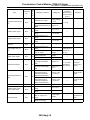
2004 LEGACY SERVICE MANUAL
QUICK REFERENCE INDEX
TRANSMISSION SECTION
This service manual has been prepared
to provide SUBARU service personnel
with the necessary information and data
for the correct maintenance and repair
of SUBARU vehicles.
This manual includes the procedures
for maintenance, disassembling, reassembling, inspection and adjustment of
components and diagnostics for guidance of experienced mechanics.
Please peruse and utilize this manual
fully to ensure complete repair work for
satisfying our customers by keeping
their vehicle in optimum condition.
When replacement of parts during
repair work is needed, be sure to use
SUBARU genuine parts.
CONTROL SYSTEMS
CS
AUTOMATIC TRANSMISSION
4AT
AUTOMATIC TRANSMISSION
(DIAGNOSTICS)
4AT(diag)
AUTOMATIC TRANSMISSION
5AT
AUTOMATIC TRANSMISSION
(DIAGNOSTICS)
5AT(diag)
MANUAL TRANSMISSION AND
DIFFERENTIAL
5MT
CLUTCH SYSTEM
CL
All information, illustration and specifications contained in this manual are
based on the latest product information
available at the time of publication
approval.
FUJI HEAVY INDUSTRIES LTD.
G2320GE5
AUTOMATIC TRANSMISSION
(DIAGNOSTICS)
5AT(diag)
1.
2.
3.
4.
5.
6.
7.
8.
9.
10.
11.
12.
13.
14.
15.
16.
Page
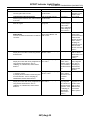
Basic Diagnostics Procedure ......................................................................2
Check List for Interview...............................................................................4
General Description ....................................................................................5
Electrical Component Location ...................................................................7
Transmission Control Module (TCM) I/O Signal .......................................12
Subaru Select Monitor...............................................................................16
Read Diagnostic Trouble Code (DTC) ......................................................19
Inspection Mode........................................................................................20
Clear Memory Mode..................................................................................21
Learning Control........................................................................................22
SPORT Indicator Light Display .................................................................23
Diagnostic Procedure for Select Monitor Communication.........................26
List of Diagnostic Trouble Code (DTC) .....................................................30
Diagnostic Procedure with Diagnostic Trouble Code (DTC) .....................34
Diagnostic Procedure without Diagnostic Trouble Code (DTC) ..............138
General Diagnostic Table........................................................................147
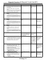
Basic Diagnostics Procedure
AUTOMATIC TRANSMISSION (DIAGNOSTICS)
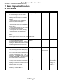
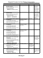
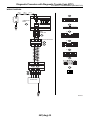
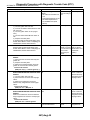
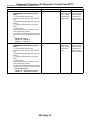
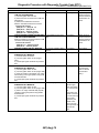
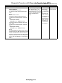
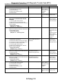
1. Basic Diagnostics Procedure
A: PROCEDURE
1
2
3
4
5
Step
CHECK PRE-INSPECTION.
1) Ask the customer when and how the trouble occurred using the interview checklist.
<Ref. to 5AT(diag)-4, Check List for Interview.>
2) Before performing diagnosis, inspect the
following items which might influence the AT
problems.
• General inspection <Ref. to 5AT(diag)-5,
INSPECTION, General Description.>
• Oil Leakage
• Stall speed test <Ref. to 5AT-31, Stall Test.>
• Line Pressure Test <Ref. to 5AT-34, Line
Pressure Test.>
• Transfer Clutch Pressure Test <Ref. to 5AT36, Transfer Clutch Pressure Test.>
• Time Lag Test <Ref. to 5AT-33, Time Lag
Test.>
• Road Test <Ref. to 5AT-30, Road Test.>
• Inhibitor Switch <Ref. to 5AT-51, Inhibitor
Switch.>
CHECK SPORT INDICATOR LIGHT.
After the ignition switch is turned to “ON”, wait
for at least 2 seconds.
CHECK SPORT INDICATOR LIGHT.
1) Turn the ignition switch to OFF.
2) Check the SPORT indicator light. <Ref. to
5AT(diag)-24, INSPECTION, SPORT Indicator
Light Display.>
3) After the ignition switch is turned to ON,
wait for at least 2 seconds.
CHECK DTC.
Read the DTC. <Ref. to 5AT(diag)-19, OPERATION, Read Diagnostic Trouble Code (DTC).>
Check
Yes
Is the unit that might influence Go to step 2.
the AT problem normal?
No
Repair or replace
each item.
Does the SPORT indicator
light illuminate?
Go to step 4.
Go to step 3.
Does the SPORT indicator
light blink?
Go to step 4.
Go to step 5.
Is DTC displayed?
Go to step 6.
Go to step 5.
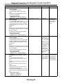
NOTE:
If the communication function of the Subaru Select Monitor cannot be executed normally,
check the communication circuit. <Ref. to
5AT(diag)-26, COMMUNICATION FOR INITIALIZING IMPOSSIBLE, Diagnostic Procedure for Select Monitor Communication.>
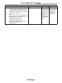
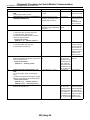
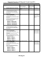
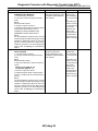
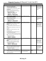
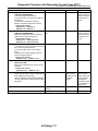
PERFORM THE GENERAL DIAGNOSTICS. Is DTC displayed?
1) Inspect using “Diagnostic Procedure without Diagnostic Trouble Code (DTC)”. <Ref. to
5AT(diag)-138, Diagnostic Procedure without
Diagnostic Trouble Code (DTC).>
2) Perform clear memory mode.
3) Perform the inspection mode. <Ref. to
5AT(diag)-20, Inspection Mode.>
4) Display DTC.
5AT(diag)-2
NOTE:
Record all DTC.
Go to step 6.
Inspect using
“General Diagnostic Table”. <Ref. to
5AT(diag)-147,
General Diagnostic Table.>
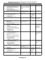
Basic Diagnostics Procedure
AUTOMATIC TRANSMISSION (DIAGNOSTICS)
6
Step
Check
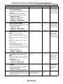
PERFORM THE DIAGNOSIS.
Is DTC displayed?
1) Inspect using the “Diagnostic Procedure
with Diagnostic Trouble Code (DTC)”. <Ref. to
5AT(diag)-34, Diagnostic Procedure with Diagnostic Trouble Code (DTC).>
NOTE:
For DTC table, refer to “List of Diagnostic Trouble Code (DTC)”. <Ref. to 5AT(diag)-30, List of
Diagnostic Trouble Code (DTC).>
2) Repair the trouble cause.
3) Perform clear memory mode.
4) Perform the inspection mode. <Ref. to
5AT(diag)-20, Inspection Mode.>
5) Display DTC.
5AT(diag)-3
Yes
Inspect using the
“Diagnostic Procedure with Diagnostic Trouble Code
(DTC)”. <Ref. to
5AT(diag)-34,
Diagnostic Procedure with Diagnostic Trouble Code
(DTC).>
No
Inspect using
“General Diagnostic Table”. <Ref. to
5AT(diag)-147,
General Diagnostic Table.>
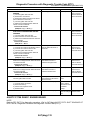
Check List for Interview
AUTOMATIC TRANSMISSION (DIAGNOSTICS)
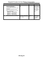
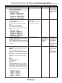
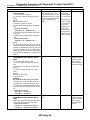
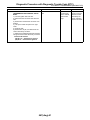
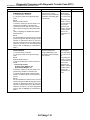
2. Check List for Interview
A: INSPECTION
Check the following items when problem has occurred.
NOTE:
Use copies of this page for interviewing customers.
Customer’s name
Date of sale
Date of repair
Trans. model
Odometer reading
Symptom
Frequency
Weather
Place
Ambient air temperature
Vehicle speed
AT warning light (SPORT indicator
light)
Select lever position
Driving condition
Manual mode
TRANSMISSION
V.I.N.
km (miles)
❏ No up-shift
❏ No down-shift
❏ No kick down
❏ Vehicle does not move (❏ Any position ❏ Particular position)
❏ Lock-up malfunction
❏ Noise or vibration
❏ Shift shock or slip
❏ Select lever does not move
❏ Others
(
)
❏ Continuous ❏ Intermittent (
times a day)
❏ Fine ❏ Cloudy ❏ Rainy ❏ Snowy
❏ Others
(
)
❏ Highland ❏ Suburbs ❏ Inner city ❏ Uphill ❏ Rough road
❏ Others
(
)
❏ Hot ❏ Warm ❏ Cool ❏ Cold
km/h (MPH)
❏ Blinks continuously
❏P ❏R ❏N ❏D
❏ Not affected
❏ At racing
❏ When decelerating
❏ ON ❏ OFF
❏ Not blink
❏ Manual mode
❏ At starting
❏ While idling
❏ When accelerating
❏ While cruising
❏ While turning (❏ RH / ❏ LH)
5AT(diag)-4
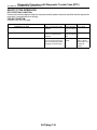
General Description
AUTOMATIC TRANSMISSION (DIAGNOSTICS)
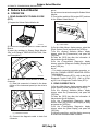
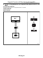
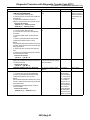
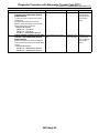
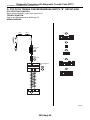
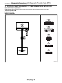
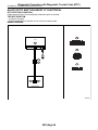
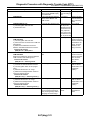
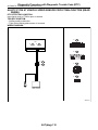
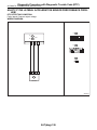
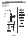
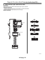
3. ATF LEVEL
A: CAUTION
Make sure that ATF level is in the specification.
<Ref. to 5AT-27, INSPECTION, Automatic Transmission Fluid.>
CAUTION:
• All airbag system wiring harnesses and connectors are colored yellow. Do not use an electric test equipment on these circuits.
• Be careful not to damage the airbag system
wiring harness when performing diagnostics
and servicing the TCM.
• Measurement
When measuring the voltage and resistance of the
ECM, TCM or each sensor, use a tapered pin with
a diameter of less than 0.64 mm (0.025 in) in order
to avoid poor contact. Do not insert a pin more than
0.65 mm (0.026 in) diameter.
(A)
(C)
F
(D)
(E)
Measure battery voltage and specific gravity of
electrolyte.
Standard voltage: 12 V or more
(B)
(C)
(D)
AT-01450
(A)
(B)
(C)
(D)
(E)
B: INSPECTION
1. BATTERY
COLD
L
• Supplemental Restraint System
The airbag system wiring harness is routed near
the TCM.
L
F
HOT
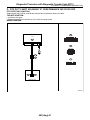
3. General Description
Level gauge
Check position when “HOT”
Upper level
Lower level
Check position when “COLD”
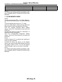
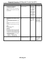
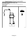
4. FRONT DIFFERENTIAL OIL LEVEL
Make sure the front differential oil level is in the
specification. <Ref. to 5AT-29, INSPECTION, Differential Gear Oil.>
Specific gravity: More than 1.260
2. TRANSMISSION GROUND
L
F
Make sure that the ground terminal bolt is tightened
securely.
• Chassis side
(A)
(B)
Tightening torque:
13 N⋅m (1.3 kgf-m, 9.4 ft-lb)
AT-00317
(A) Upper level
(B) Lower level
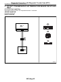
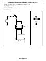
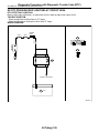
5. OPERATION OF SHIFT SELECT LEVER
Make sure there is no abnormal noise, dragging or
contact pattern in each select lever range.
AT-01464
WARNING:
Stop the engine while checking operation of the
select lever.
5AT(diag)-5
General Description
AUTOMATIC TRANSMISSION (DIAGNOSTICS)
• LHD model
• RHD model
AT-01465
AT-02048
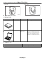
C: PREPARATION TOOL
1. SPECIAL TOOL
ILLUSTRATION
TOOL NUMBER
24082AA230
DESCRIPTION
CARTRIDGE
REMARKS
Troubleshooting for electrical system.
22771AA030
SUBARU SELECT
MONITOR KIT
Troubleshooting for electrical system.
• English: 22771AA030 (Without printer)
• German: 22771AA070 (Without printer)
• French: 22771AA080 (Without printer)
• Spanish: 22771AA090 (Without printer)
ST24082AA230
ST22771AA030
2. GENERAL TOOL
TOOL NAME
Circuit tester
Oscilloscope
REMARKS
Used for measuring resistance, voltage and current.
Used for measuring sensor.
5AT(diag)-6
Electrical Component Location
AUTOMATIC TRANSMISSION (DIAGNOSTICS)
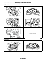
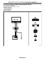
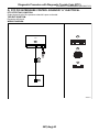
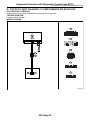
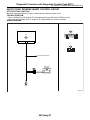
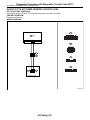
4. Electrical Component Location
A: LOCATION
1. CONTROL MODULE
• LHD model
(1)
(3)
(4) (2)
(5)
AT-02049
(1)
(2)
Engine control module (ECM)
SPORT indicator light (AT warning
light)
(3)
Transmission control module
(TCM)
(4)
(5)
Data link connector
Body integrated unit
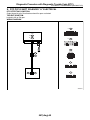
• RHD model
(3)
(2) (4)
(5)
(1)
AT-01467
(1)
(2)
Engine control module (ECM)
SPORT indicator light (AT warning
light)
(3)
Transmission control module
(TCM)
5AT(diag)-7
(4)
(5)
Data link connector
Body integrated unit
Electrical Component Location
AUTOMATIC TRANSMISSION (DIAGNOSTICS)
• LHD model
(1)
(2)
AT-01470
AT-02051
(4)
(3)
AT-02053
AT-02052
(5)
AT-02054
• RHD model
(1)
(2)
AT-01468
5AT(diag)-8
AT-01470
Electrical Component Location
AUTOMATIC TRANSMISSION (DIAGNOSTICS)
(4)
(3)
AT-01469
AT-01471
(5)
AT-01472
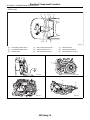
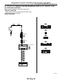
2. SENSOR
• LHD model
(3)
(5),(8)
(1) (2)
(6),(9)
(7)
(4)
AT-02050
5AT(diag)-9
Electrical Component Location
AUTOMATIC TRANSMISSION (DIAGNOSTICS)
• RHD model
(1)
(3)
(5),(8)
(6),(9)
(2)
(7)
(4)
AT-01443
(1)
(2)
(3)
Accelerator position sensor
Front vehicle speed sensor
Inhibitor switch
(4)
(5)
(6)
Rear vehicle speed sensor
Turbine speed sensor 1
ATF temperature sensor 1
(7)
(8)
(9)
Lateral G sensor
Turbine speed sensor 2
ATF temperature sensor 2
(2)
(1)
AT-00375
AT-01447
(5)
(4)
(3)
AT-01445
5AT(diag)-10
AT-01448
Electrical Component Location
AUTOMATIC TRANSMISSION (DIAGNOSTICS)
(7)
(6)
AT-01446
AT-01475
(9)
(8)
AT-01759
AT-01760
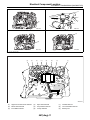
3. SOLENOID
(3)
(2)
(4)
(7)
(8)
(6)
(5)
(1)
(9)
AT-01449
(1)
(2)
(3)
High & low reverse clutch solenoid
Direct clutch solenoid
Front brake solenoid
(4)
(5)
(6)
Input clutch solenoid
Line pressure solenoid
Lock up solenoid
5AT(diag)-11
(7)
(8)
(9)
Transfer solenoid
Low coast brake solenoid
Memory box
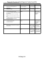
Transmission Control Module (TCM) I/O Signal
AUTOMATIC TRANSMISSION (DIAGNOSTICS)
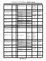
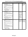
5. Transmission Control Module (TCM) I/O Signal
A: ELECTRICAL SPECIFICATION
B55
B54
1 2 3 4
10 11 12 13
19 20 21
5 6
14 15
7
16
22
1 2 3 4
10 11 12 13
19 20 21
8 9
17 18
23 24
5 6 7
14 15 16
22
8
17
23
9
18
24
AT-01451
NOTE:
The measurement should perform after warming up.
Item
P/L solenoid output
PVIGN power supply
I/C oil pressure switch
input
Power GND
CAN communication line
(+)
CAN communication line
(−)
ATF temperature sensor
1 input
Connector
No.
B54
Termin
al
No.
9
Measuring conditions
Engine ON, “P” range,
Accelerator OFF, Brake
ON
Manual mode 1st, Accelerator OFF, Brake ON
8
Ignition switch ON
7
Ignition switch ON
B54
Approx. 4.0 —
6.0 V
Approx. 2.0 —
4.0 V
Power supply
voltage
Power supply
voltage
5
B54
4
—
—
—
B54
3
—
—
—
2
Ignition switch ON
5AT(diag)-12
2.5 — 2.9 V
(ATF temperature 20°C
(68°F))
0.8 — 1.0 V
(ATF temperature 80°C
(176°F))
Driving frequency 750 —
850 Hz
—
B54
Approx. 0 V
Remarks
—
6
Always
—
3 — 9 Ω (ATF
temperature
20°C (68°F))
B54
B54
—
Voltage (V)
Measure the
resistance
between terminal and chassis
ground.
—
—
4.0 — 5.0 kΩ
(ATF temperature 20°C
(68°F))
0.7 — 0.9 kΩ
(ATF temperature 80°C
(176°F))
The condition
of I/C oil pressure switch
cannot read by
the tester.
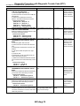
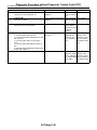
Transmission Control Module (TCM) I/O Signal
AUTOMATIC TRANSMISSION (DIAGNOSTICS)
Item
Battery power supply
I/C solenoid output
H&LR/C solenoid output
Connector
No.
Termin
al
No.
B54
1
B54
B54
Control valve power supply output
B54
LC/B solenoid output
B54
Power GND
Analog GND (Sensor
GND)
LC/B oil pressure switch
input
18
17
16
Measuring conditions
Always
While driving at 1st — 3rd
of manual mode
While driving at 4th or 5th
of manual mode
While driving at 2nd of
manual mode
While driving at 3rd — 5th
of manual mode
Ignition switch ON
B54
14
Ignition switch OFF
While driving at 1st — 2nd
of manual mode
While driving at 3rd — 5th
of manual mode
Always
B54
13
Always
B54
15
12
—
Voltage (V)
Power supply
voltage
Approx. 5.5 —
7.5 V
Approx. 0 V
Approx. 5.5 —
7.5 V
Approx. 0 V
Power supply
voltage
Approx. 0 V
Power supply
voltage
Approx. 0 V
11
Ignition switch ON
PVIGN power supply
relay output
B54
10
Ignition switch ON
0 — 1.5 V
24
While driving at other than
4th of manual mode
While driving at 4th of
manual mode
Approx. 4.5 —
6.5 V
D/C solenoid output
B54
B54
23
22
When lock-up
When not lock-up
While driving at 1st or 5th
of manual mode
While driving at 2nd — 4th
of manual mode
3 — 9 Ω (ATF
temperature
20°C (68°F))
Driving frequency 750 —
850 Hz
—
5 — 17 Ω (ATF
temperature
25°C (77°F))
—
B54
L/U solenoid output
Driving frequency 750 —
850 Hz
Approx. 0 V
ATF temperature sensor
2 input
B54
3 — 9 Ω (ATF
temperature
20°C (68°F))
—
—
Approx. 0 V
Approx. 3.5 —
5.5 V
Approx. 0 V
Approx. 5.5 —
7.5 V
Approx. 0 V
—
The condition
of LC/B oil
pressure switch
cannot read by
the tester.
3.0 — 3.6 kΩ
(ATF temperature 20°C
(68°F))
0.4 — 0.6 kΩ
(ATF temperature 80°C
(176°F))
—
3 — 9 Ω (ATF
temperature
20°C (68°F))
Driving frequency 750 —
850 Hz
3 — 9 Ω (ATF
temperature
20°C (68°F))
Driving frequency 750 —
850 Hz
3 — 9 Ω (ATF
temperature
20°C (68°F))
Driving frequency 750 —
850 Hz
D/C oil pressure switch
input
B54
21
—
—
—
Subaru Select Monitor
communication line
B54
20
—
—
—
5AT(diag)-13
Remarks
—
Approx. 0 V
2.3 — 2.7 V
(ATF temperature 20°C
(68°F))
0.6 — 0.8 V
(ATF temperature 80°C
(176°F))
Fr/B solenoid output
Measure the
resistance
between terminal and chassis
ground.
The condition
of D/C oil pressure switch
cannot read by
the tester.
Transmission Control Module (TCM) I/O Signal
AUTOMATIC TRANSMISSION (DIAGNOSTICS)
Connector
No.
Termin
al
No.
Control GND
B54
19
H&LR/C oil pressure
switch input
B55
8
Item
Front vehicle speed sensor input
Lateral G sensor power
supply
Lateral G sensor signal
input
Inhibitor switch 1 input
Inhibitor switch 2 input
Accessory power supply
B55
7
B55
6
B55
5
B55
4
B55
B55
3
2
Measuring conditions
Always
While driving at 2nd of
manual mode
While driving at 3rd — 5th
of manual mode
While driving at 2nd and
20 km/h (12 MPH) of manual mode
While driving at 4th and 80
km/h (50 MPH) of manual
mode
Approx. 0 V
Power supply
voltage
Ignition switch ON
4.75 — 5.25 V
—
2.0 — 3.0 V
—
Ignition switch ON, Engine
ON, Flat value
Ignition switch ON, “P”
range
Ignition switch ON, “N”
range
Ignition switch ON, “P”
range
Ignition switch ON, “D”
range
Accessory switch ON
Accessory switch OFF
Ignition power supply
B55
Rear vehicle speed sensor input
B55
Fr/B oil pressure switch
input
B55
Turbine speed sensor 1
input
B55
1
18
17
16
Voltage (V)
Measure the
resistance
between terminal and chassis
ground.
—
Ignition switch ON
Ignition switch OFF
While driving at 2nd and
20 km/h (12 MPH) of manual mode
While driving at 4th and 80
km/h (50 MPH) of manual
mode
Ignition switch ON, Engine
ON, While driving at other
than 4th
Ignition switch ON, Engine
ON, While driving at 4th
2nd of manual mode, Turbine speed sensor is
2,000 rpm (Read from
Subaru Select Monitor)
4th of manual mode, Turbine speed sensor is
2,000 rpm (Read from
Subaru Select Monitor)
5AT(diag)-14
Remarks
—
Approx. 0 V
Approx. 140 —
170 Hz
—
Approx. 560 —
680 Hz
4.0 — 5.0 V
—
1.5 V or less
4.0 — 5.0 V
—
1.5 V or less
Power supply
voltage
Approx. 0 V
Power supply
voltage
Approx. 0 V
—
—
Approx. 190 —
230 Hz
—
Approx. 760 —
920 Hz
Approx. 0 V
—
Power supply
voltage
Use an oscilloscope.
Approx. 0 Hz
—
Approx. 1,900
— 2,100 Hz
Use an oscilloscope.
Transmission Control Module (TCM) I/O Signal
AUTOMATIC TRANSMISSION (DIAGNOSTICS)
Item
Range lock solenoid output
Inhibitor switch 3 input
Inhibitor switch 4 input
Control valve communication line
Connector
No.
Termin
al
No.
Ignition switch ON, While
stopping at “D” range
B55
B55
B55
B55
15
14
13
12
Back-up light relay output
B55
11
Ignition power supply
B55
10
AWD solenoid output
Turbine speed sensor 2
input
B55
B55
23
22
Control GND
B55
21
Inhibitor switch 3 open
circuit monitor input
B55
20
PN signal output
Measuring conditions
B55
19
Ignition switch ON, Vehicle
speed at least 20 km/h (12
MPH)
Ignition switch ON, “R”
range
Ignition switch ON, “D”
range
Ignition switch ON, “P”
range
Ignition switch ON, “D”
range
Voltage (V)
About Power
Supply Voltage
− 1.2 V
Ignition switch ON
Ignition switch OFF
Engine ON, “P” range or
“N” range, Accelerator
OFF
Engine ON, “D” range,
Accelerator OFF, Brake
ON
2nd of manual mode, Turbine speed sensor is
2,000 rpm (Read from
Subaru Select Monitor)
4th of manual mode, Turbine speed sensor is
2,000 rpm (Read from
Subaru Select Monitor)
Always
Ignition switch ON, “D”
range
Ignition switch ON, “R”
range
Ignition switch ON, Other
than “P” range or “N”
range
Ignition switch ON, “P”
range or “N” range
5AT(diag)-15
Remarks
7 — 21 Ω
Approx. 0 V
4.0 — 5.0 V
—
1.5 V or less
4.0 — 5.0 V
—
1.5 V or less
—
Ignition switch ON, “R”
range
Ignition switch ON, Other
than “R” range
Measure the
resistance
between terminal and chassis
ground.
—
1.5 V
Power supply
voltage
Power supply
voltage
Approx. 0 V
Approx. 0 V
Approx. 2.0 —
3.0 V
—
Approx. 90 —
110 Ω (ATF temperature 25°C
(77°F))
—
3 — 9 Ω (ATF
temperature
20°C (68°F))
Approx. 1,300
— 1,500 Hz
Driving frequency 750 —
850 Hz
Use an oscilloscope.
Approx. 1,900
— 2,100 Hz
—
Approx. 0 V
—
Use an oscilloscope.
4.0 — 5.0 V
—
Less than 1.5 V
Power supply
voltage
—
0 — 1.0 V
—
ECM should
connected correctly
Subaru Select Monitor
AUTOMATIC TRANSMISSION (DIAGNOSTICS)
6. Subaru Select Monitor
A: OPERATION
1. READ DIAGNOSTIC TROUBLE CODE
(DTC)
NOTE:
Do not connect scan tools except for Subaru Select
Monitor.
5) Turn ignition switch to ON (engine OFF) and turn
on the Subaru Select Monitor.
1) Prepare the Subaru Select Monitor kit.
(A)
AT-00341
AT-00338
2) Connect the diagnosis cable to Subaru Select
Monitor.
3) Insert the cartridge to Subaru Select Monitor.
<Ref. to 5AT(diag)-6, PREPARATION TOOL, General Description.>
AT-00339
4) Connect the Subaru Select Monitor to data link
connector.
(1) Data link connector is located in the lower
portion of the instrument panel (on the driver’s
side).
(1)
AT-01712
(1) Data link connector
(2) Connect the diagnosis cable to data link
connector.
(A) Power switch
6) On the «Main Menu» display screen, select the
{Each System Check} and press the [YES] key.
7) On the «System Selection Menu» display
screen, select the {Transmission} and press the
[YES] key.
8) Press the [YES] key after the information of
transmission type is displayed.
9) On the «Transmission Diagnosis» display
screen, select the {Diagnosis Code(s) Display} and
press [YES] key.
NOTE:
• For details concerning operation procedure, refer to the “SUBARU SELECT MONITOR OPERATION MANUAL”.
• For details concerning DTCs, refer to the List of
Diagnostic Trouble Code (DTC). <Ref. to 5AT(diag)-30, List of Diagnostic Trouble Code (DTC).>
2. READ CURRENT DATA
1) On the «Main Menu» display screen, select the
{Each System Check} and press the [YES] key.
2) On the «System Selection Menu» display
screen, select the {Transmission} and press the
[YES] key.
3) Press the [YES] key after the information of
transmission type is displayed.
4) On the «Transmission Diagnosis» display
screen, select the {Current Data Display & Save}
and press the [YES] key.
5) On the «Transmission Diagnosis» display
screen, select the {Data Display} and press the
[YES] key.
6) Using the scroll key, scroll the display screen up
or down until the desired data is shown.
5AT(diag)-16
Subaru Select Monitor
AUTOMATIC TRANSMISSION (DIAGNOSTICS)
• A list of the support data is shown in the following table.
Item
Engine speed signal
Battery voltage
Accelerator Position Sensor
Front vehicle speed sensor signal
Gear position
Turbine speed sensor signal
Rear vehicle speed sensor signal
Lateral G sensor
ATF Temperature Sensor 1 Signal
ATF Temperature Sensor 2 Signal
Turbine speed sensor 1 signal
Turbine speed sensor 2 signal
High & Low Reverse Clutch Solenoid Indicator Current
Direct Clutch Solenoid Indicator Current
Front Brake Solenoid Indicator Current
Input Clutch Solenoid Indicator Current
Line Pressure Solenoid Indicator Current
Lock-up Solenoid Indicator Current
Transfer Solenoid Indicator Current
High & Low Reverse Clutch Solenoid Target Oil Pressure
Direct Clutch Solenoid Target Oil Pressure
Front Brake Solenoid Target Oil Pressure
Input Clutch Solenoid Target Oil Pressure
Line Pressure Solenoid Target Oil Pressure
Lock-up Solenoid Target Oil Pressure
Transfer Solenoid Target Oil Pressure
Ignition switch
Tip signal
Cruise control On signal
Tip Down Shift Signal
Stop light switch signal
Tip Up Shift Signal
Drive range signal
Reverse range signal
Diagnosis Light Output Signal
Shift lock solenoid signal
Parking range signal
P/N Range Output Signal
Neutral range signal
Inhibitor Switch 1 Input Signal
Inhibitor Switch 2 Input Signal
Inhibitor Switch 3 Input Signal
Inhibitor Switch 4 Input Signal
Inhibitor Switch 3 Monitor Input Signal
Backup light relay output signal
High & Low Reverse Clutch Oil Pressure Switch Input Signal
Direct Clutch Oil Pressure Switch Input Signal
Front Brake Oil Pressure Switch Input Signal
Input Clutch Oil Pressure Switch Input Signal
Display
Engine speed
Battery Voltage
Acceleration opening angle
Front Wheel Speed
Gear Position
Turbine Revolution Speed
Rear Wheel Speed
Lateral G sensor
ATF Temp.
ATF Temp. 2
Turbine Revolution Speed 1
Turbine Revolution Speed 2
H&LR/C Solenoid Current
D/C Solenoid Current
F/B Solenoid Current
I/C Solenoid Current
P/L Solenoid Current
L/U Solenoid Current
AWD Solenoid Current
H&LR/C Solenoid Target Pressure
D/C Solenoid Target Pressure
F/B Solenoid Target Pressure
I/C Solenoid Target Pressure
P/L Solenoid Target Pressure
L/U Solenoid Target Pressure
AWD Solenoid Target Pressure
Ignition SW
Tip Mode SW
Cruise Control Signal
Down SW
Stop Light SW
Up SW
D Range
R Range
Diagnosis Lamp
Shift lock solenoid
P range
P/N Signal
N range
Inhibitor SW1
Inhibitor SW2
Inhibitor SW3
Inhibitor SW4
Inhibitor SW3 Monitor
Back-up light relay
H&LR/C Oil Pressure SW
D/C Oil Pressure SW
Fr/B Oil Pressure SW
I/C Oil Pressure SW
5AT(diag)-17
Unit of measure
rpm
V
%
km/h
—
rpm
km/h
V
°C
°C
rpm
rpm
A
A
A
A
A
A
A
kPa
kPa
kPa
kPa
kPa
kPa
kPa
ON Input or OFF Input
ON or OFF
ON or OFF
ON or OFF
ON or OFF
ON or OFF
ON or OFF
ON or OFF
ON or OFF
ON or OFF
ON or OFF
ON or OFF
ON or OFF
High or Low
High or Low
High or Low
High or Low
High or Low
ON or OFF
ON or OFF
ON or OFF
ON or OFF
ON or OFF
Subaru Select Monitor
AUTOMATIC TRANSMISSION (DIAGNOSTICS)
Item
Low Coast Brake Oil Pressure Switch Input Signal
Low Coast Brake Solenoid Input Signal
Display
LC/B Oil Pressure SW
LC B Solenoid
NOTE:
For details concerning operation procedure, refer
to the “SUBARU SELECT MONITOR OPERATION
MANUAL”.
3. CLEAR MEMORY MODE
NOTE:
To clear the previous DTC, use {Clear Memory},
and to clear the learned value, use {Clear Memory
2}.
1) Check that the select lever is in “P” range.
2) On the «Main Menu» display screen, select the
{Each System Check} and press the [YES] key.
3) On the «System Selection Menu» display
screen, select the {Transmission} and press the
[YES] key.
4) Press the [YES] key after the information of
transmission type is displayed.
5) On the «Transmission Diagnosis» display
screen, select the {Clear Memory} and press the
[YES] key.
NOTE:
If {Clear Memory 2} is selected and performed,
DTC may not be cleared.
6) When the ‘Done’ are shown on the display
screen, turn off the Subaru Select Monitor and turn
the ignition switch to OFF. To turn the ignition
switch ON again, wait for more than 10 seconds.
NOTE:
For details concerning operation procedure, refer
to the “SUBARU SELECT MONITOR OPERATION
MANUAL”.
5AT(diag)-18
Unit of measure
ON or OFF
ON or OFF
Read Diagnostic Trouble Code (DTC)
AUTOMATIC TRANSMISSION (DIAGNOSTICS)
7. Read Diagnostic Trouble
Code (DTC)
A: OPERATION
Refer to “Subaru Select Monitor” for information
about how to obtain and understand the DTC.
<Ref. to 5AT(diag)-16, OPERATION, Subaru Select Monitor.>
NOTE:
DTC can not be read by SPORT indicator light.
5AT(diag)-19
Inspection Mode
AUTOMATIC TRANSMISSION (DIAGNOSTICS)
8. Inspection Mode
A: PROCEDURE
WARNING:
Observe the traffic law during actual driving.
1) Shift the select lever to “D” range, and then drive
the vehicle with changing the gear from 1st to 5th.
2) When driving the vehicle at 5th speed of “D”
range, set the gear to manual mode and drive the
vehicle with shifting down using “−” of steering
switch or “−” of select lever from 5th → 4th, 4th →
3rd, 3rd → 2nd, 2nd → 1st.
NOTE:
At shifting down, drive the vehicle at least 10 seconds in each speed.
3) Shift the select lever to “R” range and drive the
vehicle for more than 2 seconds.
5AT(diag)-20
Clear Memory Mode
AUTOMATIC TRANSMISSION (DIAGNOSTICS)
9. Clear Memory Mode
A: OPERATION
Use “Subaru Select Monitor” to clear DTC. <Ref. to
5AT(diag)-18, CLEAR MEMORY MODE, OPERATION, Subaru Select Monitor.>
NOTE:
DTC cannot be cleared without using Subaru Select Monitor.
5AT(diag)-21
Learning Control
AUTOMATIC TRANSMISSION (DIAGNOSTICS)
10.Learning Control
A: GENERAL DESCRIPTION
Be sure to perform the {Clear Memory 2} only when
the following services are performed. And when the
shifting shock is occurred in total check with vehicle
driving, perform the learning with following procedures. <Ref. to 5AT(diag)-18, CLEAR MEMORY
MODE, OPERATION, Subaru Select Monitor.>
• Replacement of TCM
• Replacement of transmission assembly
• Replacement of TCM and transmission assembly
CAUTION:
When {Clear Memory 2} is executed, DTC may
not be cleared.
B: PROCEDURE
1) Turn the ignition switch to OFF.
2) Turn the air conditioner switch to OFF.
3) Turn the headlight switch to OFF.
4) Turn the rear defogger switch to OFF.
5) Start the engine.
6) Connect the Subaru Select Monitor to the vehicle.
7) Drive the vehicle for 5 — 10 km (3 — 6 miles) to
warm up ATF temperature more than 70 °C (158
°F).
8) With the throttle opening angle on SUBARU select monitor indicates between 10%±2%, shift the
gear from 1st → 2nd, 2nd → 3rd, 3rd → 4th, 4th →
5th while driving the vehicle at “D” range. <Ref. to
5AT(diag)-16, READ CURRENT DATA, OPERATION, Subaru Select Monitor.>
9) Repeat the step 8) until reducing of shifting
shock was felt.
10) Reducing of shifting shock was not felt though
the procedure was repeated 5 cycle, recheck that
the learning conditions (throttle opening angle, ATF
temperature, etc.) are specified and recheck that
other parts are normal.
5AT(diag)-22
SPORT Indicator Light Display
AUTOMATIC TRANSMISSION (DIAGNOSTICS)
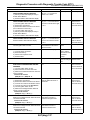
11.SPORT Indicator Light Display
A: OPERATION
When any on-board diagnostics item is malfunctioning, the display on the SPORT indicator light blinks from
the time the malfunction is detected after starting the engine until the ignition switch is turned OFF. The malfunctioning part or unit can be determined by a DTC during the on-board diagnostics operation. Problems
which occurred previously can also be identified through the memory function. If the SPORT indicator light
does not show a problem (although a problem is occurring), the problem can be determined by checking the
performance characteristics of each sensor using the Subaru Select Monitor. Indicator light signal is as
shown in the figure.
When the SPORT indicator light does not operates normally though the DTC is not stored, perform the
SPORT indicator light inspection. <Ref. to 5AT(diag)-24, INSPECTION, SPORT Indicator Light Display.>
(A)
(1)
(2)
(B)
(1)
(3)
(2)
(4)
(C)
(1)
(3)
(2)
(5)
AT-01750
(A)
Ignition switch (Engine OFF)
(B)
Normal (Engine ON)
(C)
Faulty (Engine ON)
(1)
(2)
ON
OFF
(3)
(4)
2 sec.
0.25 sec.
(5)
Blink
5AT(diag)-23
SPORT Indicator Light Display
AUTOMATIC TRANSMISSION (DIAGNOSTICS)
B: INSPECTION
DIAGNOSIS:
SPORT indicator light circuit is open or shorted.
TROUBLE SYMPTOM:
When the ignition switch is turned to ON (engine OFF), SPORT indicator light does not illuminate.
WIRING DIAGRAM:
i10
IGNITION
SWITCH
SBF-1
6 7 8 9 10
1 2 3 4 5
11 12 13 14 15 16 17 18 19 20 21 22
SBF-7
BATTERY
No.12
i77
1 2 3 4 5 6 7 8 9 10 11 12
i84
4
3
A:
1 2
3 4
5 6
7 8
9 10 11 12 13 14 15 16 17 18 19 20 21 22 23
24 25 26 27 28 29 30 31 32 33 34 35
SPORT
E
COMBINATION
METER
B54
i84
22
7
1 2 3
4 5
6 7
8 9 10 11 12 13 14 15 16 17 18 19 20
21 22 23 24 25 26 27 28 29 30
JOINT
CONNECTOR
B54
i77
A27
1 2 3 4
10 11 12 13
19 20 21
5 6
14 15
7
16
22
8
17
23
9
18
24
BODY INTEGRATED UNIT
B30
A:
B: B280
3
4
B20
B: B280
2
21
A26
8
1
i10
TCM
AT-01452
5AT(diag)-24
SPORT Indicator Light Display
AUTOMATIC TRANSMISSION (DIAGNOSTICS)
1
2
3
Step
CHECK SPORT INDICATOR LIGHT.
Turn the ignition switch to ON.
Check
Does the SPORT indicator
light illuminate?
Yes
Go to step 2.
CHECK SPORT INDICATOR LIGHT.
After the ignition switch is “ON”, wait for at least
2 seconds.
CHECK SPORT INDICATOR LIGHT.
Start the engine.
Does the SPORT indicator
light illuminate?
Go to step 3.
4
CHECK SUBARU SELECT MONITOR COMMUNICATION.
Connect the Subaru Select Monitor to data link
connector.
5
CHECK TCM.
Display the current data of TCM using Subaru
Select Monitor.
6
CHECK BODY INTEGRATED UNIT.
Display the current data of body integrated unit
using Subaru Select Monitor. <Ref. to
LAN(diag)-14, OPERATION, Subaru Select
Monitor.>
7
CHECK TCM.
1) Start the engine.
2) Display the current data of TCM using Subaru Select Monitor. <Ref. to 5AT(diag)-16,
OPERATION, Subaru Select Monitor.>
CHECK BODY INTEGRATED UNIT.
Display the current data of body integrated unit
using Subaru Select Monitor. <Ref. to
LAN(diag)-14, OPERATION, Subaru Select
Monitor.>
8
Does the SPORT indicator
light go off?
No
Perform the selfdiagnosis of combination meter.
Go to step 4.
Normal. Go back Go to step 7.
to “Basic Diagnosis Procedure”.
<Ref. to 5AT(diag)2, Basic Diagnostics Procedure.>
Is the communication between Go to step 5.
Check the TCM
Subaru Select Monitor and
power supply
TCM normal?
ground circuit and
Subaru Select
Monitor communication. <Ref. to
5AT(diag)-26,
Diagnostic Procedure for Select
Monitor Communication.>
Is “Diagnosis light” output sig- Go to step 6.
Replace the TCM.
nal set to “ON”?
<Ref. to 5AT-61,
Transmission Control Module
(TCM).>
Is “SPORT light” input signal
Replace the com- Check DTC of
set to “ON”?
bination meter
body integrated
assembly. <Ref. to unit. <Ref. to
IDI-16, Combina- LAN(diag)-14,
tion Meter Assem- OPERATION,
bly.>
Subaru Select
Monitor.>
Is “Diagnosis light” output sig- Replace the TCM. Go to step 8.
nal set to “ON”?
<Ref. to 5AT-61,
Transmission Control Module
(TCM).>
Is “SPORT light” input signal
Check DTC of
Perform the selfset to “ON”?
body integrated
diagnosis for comunit. Perform the bination meter.
diagnosis accord- <Ref. to IDI-3,
ing to DTC. <Ref. INSPECTION,
to LAN(diag)-14, Combination
OPERATION,
Meter System.>
Subaru Select
Monitor.>
5AT(diag)-25
Diagnostic Procedure for Select Monitor Communication
AUTOMATIC TRANSMISSION (DIAGNOSTICS)
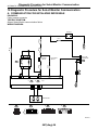
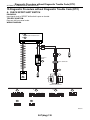
12.Diagnostic Procedure for Select Monitor Communication
A: COMMUNICATION FOR INITIALIZING IMPOSSIBLE
DIAGNOSIS:
Faulty harness connector
TROUBLE SYMPTOM:
Subaru Select Monitor communication failure
WIRING DIAGRAM:
BATTERY
SBF-1
No.13
1
2
3
SBF-7
NO.32
E
10
ACCESSORY
SWITCH
IGNITION
SWITCH
12
B357
DATA LINK
CONNECTOR
B40
NO.31
NO.12
1
4
13
16
B21
B21
A5
E
E
B21
B40
1 2 3 4
5 6 7 8
9 10 11 12
13 14 15 16
1 2 3 4 5 6 7 8
9 10 11 12 13 14 15 16
A20
B2
TCM
B55
E
A14
B:
B54
A19
A:
B1
B10
A10
A7
A8
A1
E2
TRANSMISSION
A:
B54
1 2 3 4
10 11 12 13
19 20 21
5 6
14 15
7
16
22
8 9
17 18
23 24
B:
B55
1 2 3 4
10 11 12 13
19 20 21
5 6
14 15
7
16
22
8
17
23
9
18
24
AT-01453
5AT(diag)-26
Diagnostic Procedure for Select Monitor Communication
AUTOMATIC TRANSMISSION (DIAGNOSTICS)
1
Step
Check
Yes
CHECK SUBARU SELECT MONITOR POW- Is the voltage more than 10 V? Go to step 2.
ER SUPPLY CIRCUIT.
Measure the voltage between data link connector and chassis ground.
Connector & terminal
(B40) No. 1 (+) — Chassis ground (−):
2
CHECK SUBARU SELECT MONITOR
GROUND CIRCUIT.
Measure the resistance of harness between
data link connector and chassis ground.
Connector & terminal
(B40) No. 12 — Chassis ground:
(B40) No. 13 — Chassis ground:
Is the resistance less than 1
Ω?
3
CHECK COMMUNICATION OF SUBARU SELECT MONITOR.
1) Turn the ignition switch to ON.
2) Using the Subaru Select Monitor, check
whether communication to transmission systems can be executed normally.
CHECK COMMUNICATION OF SUBARU SELECT MONITOR.
1) Turn the ignition switch to OFF.
2) Disconnect the TCM connector.
3) Turn the ignition switch to ON.
4) Check whether communication to engine
systems can be executed normally.
CHECK COMMUNICATION OF SUBARU SELECT MONITOR.
1) Turn the ignition switch to OFF.
2) Connect the TCM connector.
3) Disconnect the ECM connector.
4) Turn the ignition switch to ON.
5) Check whether communication to transmission systems can be executed normally.
CHECK HARNESS CONNECTOR BETWEEN
EACH CONTROL UNIT AND DATA LINK
CONNECTOR.
1) Turn the ignition switch to OFF.
2) Disconnect the TCM and ECM connector.
3) Measure the resistance between TCM connector and chassis ground.
Connector & terminal
(B40) No. 10 — Chassis ground:
CHECK OUTPUT SIGNAL OF TCM.
1) Turn the ignition switch to ON.
2) Measure the voltage between TCM and
chassis ground.
Connector & terminal
(B40) No. 10 (+) — Chassis ground (−):
CHECK HARNESS CONNECTOR BETWEEN
TCM AND DATA LINK CONNECTOR.
Measure the resistance between TCM connector and data link connector.
Connector & terminal
(B54) No. 20 — (B40) No. 10:
Are the name and year of sys- Go to step 8.
tem displayed on Subaru
Select Monitor?
4
5
6
7
8
Go to step 3.
No
Repair harness
connector and
connector
between battery
and data link connector, and poor
contact in coupling connector.
Repair the open
circuit in harness
between data link
connector and
ground terminal,
and poor contact
in coupling connector.
Go to step 4.
Are the name and year of sys- Go to step 6.
tem displayed on Subaru
Select Monitor?
Go to step 5.
Are the name and year of sys- Inspect the ECM.
tem displayed on Subaru
Select Monitor?
Go to step 6.
Is the resistance more than 1
MΩ?
Go to step 7.
Check harness
and connector
between each control unit and data
link connector.
Is the voltage more than 1 V?
Check harness
Go to step 8.
and connector
between each control unit and data
link connector.
Is the resistance less than 1
Ω?
Go to step 9.
5AT(diag)-27
Repair the harness and connector between TCM
and data link connector.
Diagnostic Procedure for Select Monitor Communication
AUTOMATIC TRANSMISSION (DIAGNOSTICS)
9
10
11
Step
CHECK INSTALLATION OF TCM CONNECTOR.
Turn the ignition switch to OFF.
CHECK INSTALLATION OF TRANSMISSION
HARNESS CONNECTOR.
Check
Is TCM connector connected
to TCM?
Yes
Go to step 10.
No
Connect the TCM
connector to TCM.
Is the transmission harness
connector connected to bulkhead harness connector?
Go to step 11.
Connect the bulkhead harness connector to
transmission harness connector.
Go to step 12.
CHECK POOR CONTACT IN CONNECTORS. Is there poor contact in control
unit power supply and data link
connector?
Is the voltage 10 — 13 V?
CHECK POWER SUPPLY OF TCM.
1) Disconnect the connector from TCM.
2) Turn the ignition switch to ON.
3) Measure the voltage between TCM connector and chassis ground.
Connector & terminal
(B54) No. 1 (+) — Chassis ground (−):
CHECK FUSE (No. 32).
Is the fuse (No. 32) blown out?
1) Turn the ignition switch to OFF.
2) Remove the fuse (No. 32).
Repair the poor
contact.
14
CHECK HARNESS.
Is the resistance less than 10
Measure the resistance between TCM connec- Ω?
tor and chassis ground.
Connector & terminal
(B54) No. 1 — Chassis ground:
15
CHECK IGNITION POWER SUPPLY CIRCUIT.
1) Turn the ignition switch to ON (engine
OFF).
2) Measure the ignition power supply voltage
between TCM connector and chassis ground.
Connector & terminal
(B55) No. 1 (+) — Chassis ground (−):
(B55) No. 10 (+) — Chassis ground (−):
CHECK FUSE (No. 12).
Remove the fuse (No. 12).
Replace the fuse
(No. 32). If the
replaced fuse (No.
32) has blown out
easily, repair the
short circuit in harness between fuse
(No. 32) and TCM.
Go to step 17.
Go to step 16.
12
13
16
Is the voltage 10 — 13 V?
Go to step 15.
Go to step 13.
Go to step 14.
Repair the open
circuit in harness
between fuse (No.
32) and TCM, or
fuse (No. 32) and
battery, and poor
contact in coupling connector.
Replace the fuse
(No. 32).
Is the fuse (No. 12) blown out? Replace the fuse
(No. 12). If the
replaced fuse (No.
12) has blown out
easily, repair the
short circuit in harness between fuse
(No. 12) and TCM.
5AT(diag)-28
Repair the open
circuit in harness
between fuse (No.
12) and TCM, or
fuse (No. 12) and
battery, and poor
contact in coupling connector.
Diagnostic Procedure for Select Monitor Communication
AUTOMATIC TRANSMISSION (DIAGNOSTICS)
17
18
Step
Check
Yes
CHECK HARNESS CONNECTOR BETWEEN Is the resistance more than 1 Go to step 18.
TCM AND TRANSMISSION.
MΩ?
1) Turn the ignition switch to OFF.
2) Disconnect the connectors from TCM and
transmission.
3) Measure the resistance of harness
between TCM and transmission connector.
Connector & terminal
(B54) No. 19 — Chassis ground:
(B55) No. 21 — Chassis ground:
(B54) No. 5 — Chassis ground:
(B54) No. 14 — Chassis ground:
CHECK POOR CONTACT IN CONNECTORS. Is there poor contact in TCM
Repair the conpower supply, ground and data nector.
link connector?
5AT(diag)-29
No
Repair the short
circuit in harness
between TCM and
transmission harness connector,
and poor contact
in coupling connector.
Replace the TCM.
<Ref. to 5AT-61,
Transmission Control Module
(TCM).>
List of Diagnostic Trouble Code (DTC)
AUTOMATIC TRANSMISSION (DIAGNOSTICS)
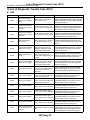
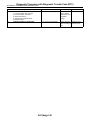
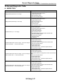
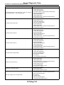
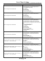
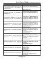
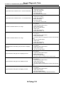
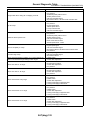
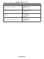
13.List of Diagnostic Trouble Code (DTC)
A: LIST
DTC
Item
Content of diagnosis
P0705
Transmission Range
Sensor Circuit (PRNDL
Input)
Inhibitor switch 1 malfunction,
open or short circuit
P0712
Transmission Fluid Temperature Sensor Circuit
Low Input
ATF temperature sensor 1 malfunction, open input signal circuit
P0713
Transmission Fluid Temperature Sensor Circuit
High Input
ATF temperature sensor 1 malfunction, short input signal circuit
P0715
Input/Turbine Speed
Sensor Circuit
Turbine speed sensor 1 malfunction, short input signal circuit
P0719
Torque Converter/Brake
Switch “B” Circuit Low
P0720
Output Speed Sensor
Circuit
P0724
Torque Converter/Brake
Switch “B” Circuit High
P0725
Engine Speed Input Circuit
P0731
Gear 1 Incorrect Ratio
P0732
Gear 2 Incorrect Ratio
P0733
Gear 3 Incorrect Ratio
Vehicle sensor, turbine speed
sensor, or shift clutch malfunction
P0734
Gear 4 Incorrect Ratio
Vehicle sensor, turbine speed
sensor, or shift clutch malfunction
P0735
Gear 5 Incorrect Ratio
Vehicle sensor, turbine speed
sensor, or shift clutch malfunction
P0736
Reverse Incorrect Ratio
Vehicle sensor, turbine speed
sensor, or shift clutch malfunction
P0741
Torque Converter Clutch
Circuit Performance or
Stuck Off
Lock-up clutch is faulty or valve is
stuck.
Brake switch malfunction, open
input signal circuit, body integrated unit malfunction, CAN
communication malfunction
Front wheel speed sensor is
faulty or input signal circuit,
ground, power supply is open or
shorted.
Brake switch malfunction, short
circuit of input signal, body integrated unit malfunction, CAN
communication malfunction
Open or short engine speed output signal circuit, ECM malfunction, CAN communication
malfunction
Vehicle sensor, turbine speed
sensor, control valve malfunction
or shift clutch malfunction
Vehicle sensor, turbine speed
sensor, control valve malfunction
or shift clutch malfunction
5AT(diag)-30
Reference target
<Ref. to 5AT(diag)-34, DTC P0705 TRANSMISSION RANGE SENSOR CIRCUIT (PRNDL
INPUT), Diagnostic Procedure with Diagnostic
Trouble Code (DTC).>
<Ref. to 5AT(diag)-39, DTC P0712 TRANSMISSION FLUID TEMPERATURE SENSOR
CIRCUIT LOW INPUT, Diagnostic Procedure
with Diagnostic Trouble Code (DTC).>
<Ref. to 5AT(diag)-42, DTC P0713 TRANSMISSION FLUID TEMPERATURE SENSOR
CIRCUIT HIGH INPUT, Diagnostic Procedure
with Diagnostic Trouble Code (DTC).>
<Ref. to 5AT(diag)-45, DTC P0715 INPUT/
TURBINE SPEED SENSOR CIRCUIT, Diagnostic Procedure with Diagnostic Trouble Code
(DTC).>
<Ref. to 5AT(diag)-49, DTC P0719 TORQUE
CONVERTER/BRAKE SWITCH “B” CIRCUIT
LOW, Diagnostic Procedure with Diagnostic
Trouble Code (DTC).>
<Ref. to 5AT(diag)-51, DTC P0720 OUTPUT
SPEED SENSOR CIRCUIT, Diagnostic Procedure with Diagnostic Trouble Code (DTC).>
<Ref. to 5AT(diag)-56, DTC P0724 TORQUE
CONVERTER/BRAKE SWITCH “B” CIRCUIT
HIGH, Diagnostic Procedure with Diagnostic
Trouble Code (DTC).>
<Ref. to 5AT(diag)-58, DTC P0725 ENGINE
SPEED INPUT CIRCUIT, Diagnostic Procedure with Diagnostic Trouble Code (DTC).>
<Ref. to 5AT(diag)-58, DTC P0731 GEAR 1
INCORRECT RATIO, Diagnostic Procedure
with Diagnostic Trouble Code (DTC).>
<Ref. to 5AT(diag)-58, DTC P0732 GEAR 2
INCORRECT RATIO, Diagnostic Procedure
with Diagnostic Trouble Code (DTC).>
<Ref. to 5AT(diag)-58, DTC P0733 GEAR 3
INCORRECT RATIO, Diagnostic Procedure
with Diagnostic Trouble Code (DTC).>
<Ref. to 5AT(diag)-58, DTC P0734 GEAR 4
INCORRECT RATIO, Diagnostic Procedure
with Diagnostic Trouble Code (DTC).>
<Ref. to 5AT(diag)-58, DTC P0735 GEAR 5
INCORRECT RATIO, Diagnostic Procedure
with Diagnostic Trouble Code (DTC).>
<Ref. to 5AT(diag)-59, DTC P0736 REVERSE
INCORRECT RATIO, Diagnostic Procedure
with Diagnostic Trouble Code (DTC).>
<Ref. to 5AT(diag)-60, DTC P0741 TORQUE
CONVERTER CLUTCH CIRCUIT PERFORMANCE OR STUCK OFF, Diagnostic Procedure with Diagnostic Trouble Code (DTC).>
List of Diagnostic Trouble Code (DTC)
AUTOMATIC TRANSMISSION (DIAGNOSTICS)
DTC
Item
P0743
Torque Converter Clutch
Circuit Electrical
P0748
Pressure Control Solenoid “A” Electrical
P0751
Shift Solenoid “A” Performance or Stuck Off
P0753
Shift Solenoid “A” Electrical
P0756
Shift Solenoid “B” Performance or Stuck Off
P0758
Shift Solenoid “B” Electrical
P0761
Shift Solenoid “C” Performance or Stuck Off
P0763
Shift Solenoid “C” Electrical
P0766
Shift Solenoid “D” Performance or Stuck Off
P0768
Shift Solenoid “D” Electrical
P0771
Shift Solenoid “E” Performance or Stuck Off
P0773
Shift Solenoid “E” Electrical
P0801
Reverse Inhibit Control
Circuit
P0817
Starter Disable Circuit
P0882
PVIGN Power Supply
Circuit (Low)
Content of diagnosis
Reference target
<Ref. to 5AT(diag)-61, DTC P0743 TORQUE
L/U solenoid circuit malfunction
CONVERTER CLUTCH CIRCUIT ELECTRIor L/U solenoid body malfunction CAL, Diagnostic Procedure with Diagnostic
Trouble Code (DTC).>
<Ref. to 5AT(diag)-63, DTC P0748 PRESLine pressure solenoid circuit
SURE CONTROL SOLENOID “A” ELECTRImalfunction or line pressure soleCAL, Diagnostic Procedure with Diagnostic
noid body malfunction
Trouble Code (DTC).>
<Ref. to 5AT(diag)-65, DTC P0751 SHIFT
Shift Solenoid “A” performance
SOLENOID “A” PERFORMANCE OR STUCK
malfunction
OFF, Diagnostic Procedure with Diagnostic
Trouble Code (DTC).>
<Ref. to 5AT(diag)-69, DTC P0753 SHIFT
Fr/B solenoid circuit malfunction
SOLENOID “A” ELECTRICAL, Diagnostic Proor Fr/B solenoid body malfunction
cedure with Diagnostic Trouble Code (DTC).>
<Ref. to 5AT(diag)-72, DTC P0756 SHIFT
Shift Solenoid “B” Performance
SOLENOID “B” PERFORMANCE OR STUCK
malfunction
OFF, Diagnostic Procedure with Diagnostic
Trouble Code (DTC).>
<Ref. to 5AT(diag)-75, DTC P0758 SHIFT
I/C solenoid circuit malfunction or
SOLENOID “B” ELECTRICAL, Diagnostic ProI/C solenoid body malfunction
cedure with Diagnostic Trouble Code (DTC).>
<Ref. to 5AT(diag)-78, DTC P0761 SHIFT
SOLENOID “C” PERFORMANCE OR STUCK
H&LR/C solenoid malfunction
OFF, Diagnostic Procedure with Diagnostic
Trouble Code (DTC).>
H&LR/C solenoid circuit malfunc- <Ref. to 5AT(diag)-82, DTC P0763 SHIFT
SOLENOID “C” ELECTRICAL, Diagnostic Protion or H&LR/C solenoid body
cedure with Diagnostic Trouble Code (DTC).>
malfunction
<Ref. to 5AT(diag)-85, DTC P0766 SHIFT
SOLENOID “D” PERFORMANCE OR STUCK
D/C solenoid malfunction
OFF, Diagnostic Procedure with Diagnostic
Trouble Code (DTC).>
<Ref. to 5AT(diag)-88, DTC P0768 SHIFT
D/C solenoid circuit malfunction
SOLENOID “D” ELECTRICAL, Diagnostic Proor D/C solenoid body malfunction
cedure with Diagnostic Trouble Code (DTC).>
<Ref. to 5AT(diag)-91, DTC P0771 SHIFT
SOLENOID “E” PERFORMANCE OR STUCK
LC/B solenoid malfunction
OFF, Diagnostic Procedure with Diagnostic
Trouble Code (DTC).>
• LC/B solenoid circuit malfunction or LC/B solenoid body mal<Ref. to 5AT(diag)-94, DTC P0773 SHIFT
function
SOLENOID “E” ELECTRICAL, Diagnostic Pro• OFF malfunction of PVIGN
cedure with Diagnostic Trouble Code (DTC).>
relay circuit or relay body
• Shift lock solenoid is faulty or
<Ref. to 5AT(diag)-97, DTC P0801 REVERSE
output signal circuit is open or
INHIBIT CONTROL CIRCUIT, Diagnostic Proshorted.
cedure with Diagnostic Trouble Code (DTC).>
• Brown out of TCM+B fuse
• PN signal output circuit is open
or shorted.
<Ref. to 5AT(diag)-100, DTC P0817 STARTER
• ECM Source Voltage Is Abnor- DISABLE CIRCUIT, Diagnostic Procedure with
mal
Diagnostic Trouble Code (DTC).>
• Brown out of TCM+B fuse
PVIGN relay output circuit is
<Ref. to 5AT(diag)-102, DTC P0882 TCM
open, shorted or relay malfuncPOWER INPUT SIGNAL LOW, Diagnostic Protion
cedure with Diagnostic Trouble Code (DTC).>
5AT(diag)-31
List of Diagnostic Trouble Code (DTC)
AUTOMATIC TRANSMISSION (DIAGNOSTICS)
DTC
Item
Content of diagnosis
Back-up relay output circuit is
open, shorted or relay OFF malfunction
Back-up relay output circuit is
open, shorted or relay ON malfunction
P0957
Backup Light Relay Circuit Low
P0958
Backup Light Relay Circuit High
P1601
TCM Communication
Malfunction
Communication Failure between
TCM and Memory Box
P1706
AT Vehicle Speed Sensor Circuit Malfunction
(Rear Wheel)
Rear wheel speed sensor is faulty
or input circuit, ground, power
supply is open or shorted.
P1707
AT AWD Solenoid Valve
Circuit Malfunction
AWD solenoid circuit malfunction
or AWD solenoid body malfunction
P1710
Torque Converter Turbine 2 Speed Signal Circuit 2 Malfunction
Torque converter sensor 2 malfunction, input circuit, ground,
power open, short circuit
P1716
ATF Temp. Sensor 2 Circuit Low
ATF temperature sensor 2 malfunction, open input signal circuit
P1717
ATF Temp. Sensor 2 Circuit High
ATF temperature sensor 2 malfunction, short input signal circuit
P1718
AT CAN Communication
Circuit
CAN communication line bus off
is open, EUM short circuit, ABS/
VDCCM, integrated CU malfunction
P1760
Lateral Acceleration
Sensor Performance
Problem
Lateral G sensor malfunction
P1761
Lateral Acceleration
Sensor Circuit Low
Lateral G sensor is faulty or input
signal circuit is open.
P1762
Lateral Acceleration
Sensor Circuit High
Lateral G sensor is faulty or input
signal circuit is shorted.
P1798
Gear 1 Engine Brake
P1799
Interlock
P1817
SPORTS Mode Switch
Circuit (Manual Switch)
Malfunction of clutch oil pressure
related to 1st engine brake, solenoid current malfunction
Malfunction of clutch oil pressure
which emit interlock, solenoid
current malfunction
Manual mode switch is open or
shorted, or switch malfunction
5AT(diag)-32
Reference target
<Ref. to 5AT(diag)-104, DTC P0957 BACKUP
LIGHT RELAY CIRCUIT LOW, Diagnostic Procedure with Diagnostic Trouble Code (DTC).>
<Ref. to 5AT(diag)-106, DTC P0958 BACKUP
LIGHT RELAY CIRCUIT HIGH, Diagnostic Procedure with Diagnostic Trouble Code (DTC).>
<Ref. to 5AT(diag)-108, DTC P1601 TCM
COMMUNICATION MALFUNCTION, Diagnostic Procedure with Diagnostic Trouble Code
(DTC).>
<Ref. to 5AT(diag)-110, DTC P1706 AT VEHICLE SPEED SENSOR CIRCUIT MALFUNCTION (REAR WHEEL), Diagnostic Procedure
with Diagnostic Trouble Code (DTC).>
<Ref. to 5AT(diag)-114, DTC P1707 AT AWD
SOLENOID VALVE CIRCUIT MALFUNCTION, Diagnostic Procedure with Diagnostic
Trouble Code (DTC).>
<Ref. to 5AT(diag)-116, DTC P1710 TORQUE
CONVERTER TURBINE 2 SPEED SIGNAL
CIRCUIT 2 MALFUNCTION, Diagnostic Procedure with Diagnostic Trouble Code (DTC).>
<Ref. to 5AT(diag)-120, DTC P1716 ATF
TEMP. SENSOR 2 CIRCUIT LOW, Diagnostic
Procedure with Diagnostic Trouble Code
(DTC).>
<Ref. to 5AT(diag)-123, DTC P1717 ATF
TEMP. SENSOR 2 CIRCUIT HIGH, Diagnostic
Procedure with Diagnostic Trouble Code
(DTC).>
<Ref. to 5AT(diag)-125, DTC P1718 AT CAN
COMMUNICATION CIRCUIT, Diagnostic Procedure with Diagnostic Trouble Code (DTC).>
<Ref. to 5AT(diag)-126, DTC P1760 LATERAL
ACCELERATION SENSOR PERFORMANCE
PROBLEM, Diagnostic Procedure with Diagnostic Trouble Code (DTC).>
<Ref. to 5AT(diag)-129, DTC P1761 LATERAL
ACCELERATION SENSOR CIRCUIT LOW,
Diagnostic Procedure with Diagnostic Trouble
Code (DTC).>
<Ref. to 5AT(diag)-131, DTC P1762 LATERAL
ACCELERATION SENSOR CIRCUIT HIGH,
Diagnostic Procedure with Diagnostic Trouble
Code (DTC).>
<Ref. to 5AT(diag)-133, DTC P1798 GEAR 1
ENGINE BRAKE, Diagnostic Procedure with
Diagnostic Trouble Code (DTC).>
<Ref. to 5AT(diag)-134, DTC P1799 INTERLOCK, Diagnostic Procedure with Diagnostic
Trouble Code (DTC).>
<Ref. to 5AT(diag)-135, DTC P1817 SPORTS
MODE SWITCH CIRCUIT (MANUAL
SWITCH), Diagnostic Procedure with Diagnostic Trouble Code (DTC).>
List of Diagnostic Trouble Code (DTC)
AUTOMATIC TRANSMISSION (DIAGNOSTICS)
DTC
Item
Content of diagnosis
P1840
Transmission Fluid Pressure Sensor/Switch A
Circuit
H&LR/C oil pressure switch is
open or shorted, or switch malfunction
P1841
Transmission Fluid Pressure Sensor/Switch B
Circuit
D/C oil pressure switch is open or
shorted, or switch malfunction
P1842
Transmission Fluid Pressure Sensor/Switch C
Circuit
Fr/B oil pressure switch is open or
shorted, or switch malfunction
P1843
Transmission Fluid Pressure Sensor/Switch D
Circuit
I/C oil pressure switch is open or
shorted, or switch malfunction
P1844
Transmission Fluid Pressure Sensor/Switch E
Circuit
LC/B oil pressure switch is open
or shorted, or switch malfunction
5AT(diag)-33
Reference target
<Ref. to 5AT(diag)-137, DTC P1840 TRANSMISSION FLUID PRESSURE SENSOR/
SWITCH A CIRCUIT, Diagnostic Procedure
with Diagnostic Trouble Code (DTC).>
<Ref. to 5AT(diag)-137, DTC P1841 TRANSMISSION FLUID PRESSURE SENSOR/
SWITCH B CIRCUIT, Diagnostic Procedure
with Diagnostic Trouble Code (DTC).>
<Ref. to 5AT(diag)-137, DTC P1842 TRANSMISSION FLUID PRESSURE SENSOR/
SWITCH C CIRCUIT, Diagnostic Procedure
with Diagnostic Trouble Code (DTC).>
<Ref. to 5AT(diag)-137, DTC P1843 TRANSMISSION FLUID PRESSURE SENSOR/
SWITCH D CIRCUIT, Diagnostic Procedure
with Diagnostic Trouble Code (DTC).>
<Ref. to 5AT(diag)-137, DTC P1844 TRANSMISSION FLUID PRESSURE SENSOR/
SWITCH E CIRCUIT, Diagnostic Procedure
with Diagnostic Trouble Code (DTC).>
Diagnostic Procedure with Diagnostic Trouble Code (DTC)
AUTOMATIC TRANSMISSION (DIAGNOSTICS)
14.Diagnostic Procedure with Diagnostic Trouble Code (DTC)
A: DTC P0705 TRANSMISSION RANGE SENSOR CIRCUIT (PRNDL INPUT)
DTC DETECTING CONDITION:
The inhibitor switch is open or short.
TROUBLE SYMPTOM:
• Shift characteristics are erroneous.
• Shift indicator light does not match with select lever.
• Shift indicator light does not illuminate.
• N-D, N-R shock occur.
5AT(diag)-34
Diagnostic Procedure with Diagnostic Trouble Code (DTC)
AUTOMATIC TRANSMISSION (DIAGNOSTICS)
WIRING DIAGRAM:
SBF-1
SBF-7
No.12
BATTERY
4
3
i10
6 7 8 9 10
1 2 3 4 5
11 12 13 14 15 16 17 18 19 20 21 22
COMBINATION
METER
P
R
N
D
i10
i77
E
21
22
1
7
1 2 3 4 5 6 7 8 9 10 11 12
A:
JOINT
CONNECTOR
2
8
A27
A26
i77
BODY INTEGRATED UNIT
A:
B54
B30
i84
B: B280
A3
A4
B20
A:
B:
i84
1 2
3 4
5 6
7 8
9 10 11 12 13 14 15 16 17 18 19 20 21 22 23
24 25 26 27 28 29 30 31 32 33 34 35
B:
B280
1 2 3
4 5
6 7
8 9 10 11 12 13 14 15 16 17 18 19 20
21 22 23 24 25 26 27 28 29 30
A:
B54
1 2 3 4
10 11 12 13
19 20 21
5 6
14 15
B:
B55
1 2 3 4
10 11 12 13
19 20 21
5 6
14 15
7
16
22
8
17
23
9
18
24
7
16
22
8
17
23
9
18
24
TCM
B55
B13
B20
8
1
B3
B14
2
3
B12
4
B4
B12
1 2 3 4
5 6 7 8
T3
TRANSMISSION
E
AT-02073
5AT(diag)-35
Diagnostic Procedure with Diagnostic Trouble Code (DTC)
AUTOMATIC TRANSMISSION (DIAGNOSTICS)
1
Step
CHECK DTC OF TCM.
2
PREPARE SUBARU SELECT MONITOR.
3
CHECK INHIBITOR SWITCH.
1) Shift the select lever to “P” range.
2) Check input signal of inhibitor SW 1 — 4
and inhibitor SW 3 monitor using Subaru
Select Monitor.
CHECK HARNESS CONNECTOR BETWEEN
TCM AND TRANSMISSION.
1) Turn the ignition switch to OFF.
2) Disconnect the connectors from TCM and
transmission.
3) Measure the resistance between TCM connector and chassis ground about the item
which indicated Low on step 3.
Connector & terminal
(B55) No. 4 — Chassis ground:
(B55) No. 3 — Chassis ground:
(B55) No. 14 — Chassis ground:
(B55) No. 13 — Chassis ground:
(B55) No. 20 — Chassis ground:
CHECK INHIBITOR SWITCH.
1) Shift the select lever to “D” range.
2) Check input signal of inhibitor SW 1 — 4
and inhibitor SW 3 monitor using Subaru
Select Monitor.
CHECK HARNESS CONNECTOR BETWEEN
TCM AND TRANSMISSION.
1) Turn the ignition switch to OFF.
2) Disconnect the connectors from TCM and
transmission.
3) Measure the resistance of harness
between TCM and transmission connector
about the item which indicated High on step 5.
Connector & terminal
(B55) No. 4 — (B12) No. 4:
(B55) No. 3 — (B12) No. 3:
(B55) No. 14 — (B12) No. 2:
(B55) No. 13 — (B12) No. 1:
(B55) No. 20 — (B12) No. 8:
CHECK HARNESS CONNECTOR BETWEEN
TCM AND TRANSMISSION.
1) Turn the ignition switch to OFF.
2) Disconnect the connectors from TCM and
transmission.
3) Measure the resistance of harness
between TCM and transmission connector.
Connector & terminal
(B55) No. 4 — (B12) No. 4:
(B55) No. 3 — (B12) No. 3:
(B55) No. 14 — (B12) No. 2:
(B55) No. 13 — (B12) No. 1:
(B55) No. 20 — (B12) No. 8:
4
5
6
7
Check
Yes
No
Is DTC of AT CAN communica- Perform the diag- Go to step 2.
tion circuit displayed?
nosis according to
DTC.
Do you have a Subaru Select Go to step 3.
Go to step 7.
Monitor?
Are all indications High?
Go to step 5.
Go to step 4.
Is the resistance more than 1
MΩ?
Go to step 9.
Repair the short
circuit in harness
between TCM connector and chassis
ground.
Are all indications High?
Go to step 9.
Go to step 6.
Is the resistance less than 1
Ω?
Go to step 9.
Repair the open
circuit in harness
between TCM connector and transmission connector.
Is the resistance less than 1
Ω?
Go to step 8.
Repair the open
circuit in harness
between TCM connector and transmission connector.
5AT(diag)-36
Diagnostic Procedure with Diagnostic Trouble Code (DTC)
AUTOMATIC TRANSMISSION (DIAGNOSTICS)
8
9
10
11
Step
CHECK HARNESS CONNECTOR BETWEEN
TCM AND TRANSMISSION.
Measure the resistance between TCM connector and chassis ground.
Connector & terminal
(B55) No. 4 — Chassis ground:
(B55) No. 3 — Chassis ground:
(B55) No. 14 — Chassis ground:
(B55) No. 13 — Chassis ground:
(B55) No. 20 — Chassis ground:
CHECK INPUT SIGNAL FOR TCM USING
CIRCUIT TESTER.
1) Turn the ignition switch to OFF.
2) Disconnect the transmission connector
(B12).
3) Connect the TCM connector.
4) Turn the ignition switch to ON.
5) Measure the voltage between TCM terminals.
Connector & terminal
(B55) No. 4 — (B54) No. 19:
(B55) No. 3 — (B54) No. 19:
(B55) No. 14 — (B54) No. 19:
(B55) No. 13 — (B54) No. 19:
(B55) No. 20 — (B54) No. 19:
CHECK TCM I/O SIGNAL.
Check I/O signal of power supply, ground and
PVIGN power supply relay.
<Ref. to 5AT(diag)-12, ELECTRICAL SPECIFICATION, Transmission Control Module (TCM)
I/O Signal.>
Check
Is the resistance more than 1
MΩ?
Yes
Go to step 9.
No
Repair the short
circuit in harness
between TCM connector and chassis
ground.
Is the voltage 4 — 6 V for the
inhibitor SW 1 — 4?
Is the voltage 3.5 — 5.5 V for
the inhibitor SW 3 monitor?
Go to step 11.
Go to step 10.
Is TCM I/O signal OK?
Replace the TCM.
<Ref. to 5AT-61,
Transmission Control Module
(TCM).>
Repair the open or
short circuit for
power supply and
ground. Perform
the diagnosis
according to DTC
for PVIGN power
supply relay.
Repair the open
circuit in harness
between control
valve body connector and transmission connector.
CHECK HARNESS CONNECTOR BETWEEN Is the resistance less than 1
Ω?
TRANSMISSION AND CONTROL VALVE
BODY.
1) Turn the ignition switch to OFF.
2) Disconnect the connector from transmission.
3) Remove the transmission connector from
bracket.
4) Lift-up the vehicle and place it on rigid
racks.
NOTE:
Raise all wheels off floor.
5) Drain the ATF.
CAUTION:
Do not drain the ATF until it cools down.
6) Remove the oil pan, and disconnect the
connector from control valve body connector.
7) Measure the resistance between transmission connector and control valve body connector.
Connector & terminal
(T3) No. 4 — (T5) No. 6:
(T3) No. 3 — (T5) No. 5:
(T3) No. 2 — (T5) No. 4:
(T3) No. 1 — (T5) No. 3:
(T3) No. 8 — (T5) No. 2:
5AT(diag)-37
Go to step 12.
Diagnostic Procedure with Diagnostic Trouble Code (DTC)
AUTOMATIC TRANSMISSION (DIAGNOSTICS)
12
13
Step
Check
Yes
CHECK HARNESS CONNECTOR BETWEEN Is the resistance more than 1 Go to step 13.
TRANSMISSION AND CONTROL VALVE
MΩ?
BODY.
Measure the resistance between transmission
ground and control valve body connector.
Connector & terminal
(T5) No. 6 — Transmission ground:
(T5) No. 5 — Transmission ground:
(T5) No. 4 — Transmission ground:
(T5) No. 3 — Transmission ground:
(T5) No. 2 — Transmission ground:
CHECK POOR CONTACT.
Is there any poor contact in
Repair the poor
inhibitor SW 1 — 4 or inhibitor contact.
SW 3 monitor circuit?
5AT(diag)-38
No
Repair the short
circuit in harness
between control
valve body connector and transmission connector.
Replace the control valve body.
<Ref. to 5AT-58,
Control Valve
Body.>
Diagnostic Procedure with Diagnostic Trouble Code (DTC)
AUTOMATIC TRANSMISSION (DIAGNOSTICS)
B: DTC P0712 TRANSMISSION FLUID TEMPERATURE SENSOR CIRCUIT LOW
INPUT
DTC DETECTING CONDITION:
Input signal circuit of TCM to ATF temperature sensor 1 is opened.
TROUBLE SYMPTOM:
Excessive shift shock.
WIRING DIAGRAM:
B54
TCM
1 2 3 4
10 11 12 13
19 20 21
5 6
14 15
7
16
22
8
17
23
9
18
24
2
13
B54
B11
1 2
3 4
6 7
8
9 10
11 12
13
14 15
16
17 18
19 20
B11
5
12
5
T4
T5
16
1
1 2 3
4 5 6
7 8 9 10 11 12 13 14 15 16
T5
TRANSMISSION
AT-02037
5AT(diag)-39
Diagnostic Procedure with Diagnostic Trouble Code (DTC)
AUTOMATIC TRANSMISSION (DIAGNOSTICS)
1
2
3
4
5
Step
CHECK HARNESS CONNECTOR BETWEEN
TCM AND TRANSMISSION.
1) Turn the ignition switch to OFF.
2) Disconnect the connectors from TCM and
transmission.
3) Measure the resistance of harness
between TCM and transmission connector.
Connector & terminal
(B54) No. 13 — (B11) No. 12:
(B54) No. 2 — (B11) No. 5:
CHECK ATF TEMPERATURE SENSOR.
1) Turn the ignition switch to OFF.
2) Connect the connectors to transmission
and TCM.
3) Turn the ignition switch to ON and start
engine.
4) Warm-up the transmission until the ATF
temperature reaches to 80°C (176°F).
NOTE:
If the ambient temperature is below 0°C (32°F),
drive the vehicle until the ATF reaches its operating temperature.
5) Disconnect the connector from transmission.
6) Measure the resistance between transmission connector terminals.
Connector & terminal
(T4) No. 5 — (T4) No. 12:
CHECK ATF TEMPERATURE SENSOR.
Measure the resistance between transmission
connector terminals.
Connector & terminal
(T4) No. 5 — (T4) No. 12:
PREPARE SUBARU SELECT MONITOR.
CHECK INPUT SIGNAL FROM TCM.
1) Connect the connector to transmission.
2) Warm-up the transmission until the ATF
temperature is approx. 80°C (176°F).
Check
Is the resistance less than 1
Ω?
Yes
Go to step 2.
No
Repair the open
circuit in harness
between TCM and
transmission connector.
Is the resistance 500 — 1,200 Go to step 3.
Ω?
Go to step 7.
Does the resistance value
Go to step 4.
increase while the ATF temperature decreases?
Go to step 7.
Do you have a Subaru Select
Monitor?
Is the voltage 0.5 — 1.2 V?
Go to step 5.
NOTE:
If the ambient temperature is below 0°C (32°F),
drive the vehicle until the ATF reaches its operating temperature.
3) Measure the voltage between TCM connector terminals.
Connector & terminal
(B54) No. 2 (+) — (B54) No. 13 (−):
5AT(diag)-40
Go to step 6.
Even if the SPORT Go to step 8.
indicator lights
blinks, the system
is in normal condition. A temporary
poor contact of
connector or harness may be the
cause. Repair the
poor contact of
harness between
ATF temperature
sensor and transmission connector.
Diagnostic Procedure with Diagnostic Trouble Code (DTC)
AUTOMATIC TRANSMISSION (DIAGNOSTICS)
6
7
Step
CHECK INPUT SIGNAL FOR TCM USING
SUBARU SELECT MONITOR.
1) Connect the connector.
2) Turn the ignition switch to ON (engine
OFF).
3) Read the ATF temperature using Subaru
Select Monitor.
Check
Does the ATF temperature
gradually decrease?
CHECK HARNESS CONNECTOR BETWEEN Is the resistance less than 1
Ω?
TRANSMISSION AND CONTROL VALVE
BODY.
1) Turn the ignition switch to OFF.
2) Disconnect the connector from transmission.
3) Remove the transmission connector from
bracket.
4) Lift-up the vehicle and place it on rigid
racks.
Yes
Even if the SPORT
indicator lights
blinks, the system
is in normal condition. A temporary
poor contact of
connector or harness may be the
cause. Repair the
poor contact of
harness between
ATF temperature
sensor and transmission connector.
Replace the control valve body.
<Ref. to 5AT-58,
Control Valve
Body.>
No
Go to step 8.
Repair the poor
contact.
Replace the TCM.
<Ref. to 5AT-61,
Transmission Control Module
(TCM).>
Repair the open
circuit in harness
between control
valve body connector and transmission connector.
NOTE:
Raise all wheels off floor.
5) Drain the ATF.
8
CAUTION:
Do not drain the ATF until it cools down.
6) Remove the oil pan, and disconnect the
connector from control valve body connector.
7) Measure the resistance between transmission connector and control valve body connector.
Connector & terminal
(T4) No. 12 — (T5) No. 1:
(T4) No. 5 — (T5) No. 16:
CHECK POOR CONTACT.
Is there poor contact in ATF
temperature sensor circuit 1?
5AT(diag)-41
Diagnostic Procedure with Diagnostic Trouble Code (DTC)
AUTOMATIC TRANSMISSION (DIAGNOSTICS)
C: DTC P0713 TRANSMISSION FLUID TEMPERATURE SENSOR CIRCUIT HIGH
INPUT
DTC DETECTING CONDITION:
Input signal circuit of TCM to ATF temperature sensor 1 is shorted.
TROUBLE SYMPTOM:
Excessive shift shock.
WIRING DIAGRAM:
B54
TCM
1 2 3 4
10 11 12 13
19 20 21
5 6
14 15
7
16
22
8
17
23
9
18
24
2
13
B54
B11
1 2
3 4
6 7
8
9 10
11 12
13
14 15
16
17 18
19 20
B11
5
12
5
T4
T5
16
1
1 2 3
4 5 6
7 8 9 10 11 12 13 14 15 16
T5
TRANSMISSION
AT-02037
5AT(diag)-42
Diagnostic Procedure with Diagnostic Trouble Code (DTC)
AUTOMATIC TRANSMISSION (DIAGNOSTICS)
1
2
3
4
5
Step
CHECK HARNESS CONNECTOR BETWEEN
TCM AND TRANSMISSION.
1) Turn the ignition switch to OFF.
2) Disconnect the connectors from TCM and
transmission.
3) Measure the resistance of harness
between TCM connector and chassis ground.
Connector & terminal
(B54) No. 13 — Chassis ground:
(B54) No. 2 — Chassis ground:
CHECK ATF TEMPERATURE SENSOR.
1) Turn the ignition switch to OFF.
2) Connect the connectors to transmission
and TCM.
3) Turn the ignition switch to ON and start
engine.
4) Warm-up the transmission until the ATF
temperature reaches to 80°C (176°F).
NOTE:
If the ambient temperature is below 0°C (32°F),
drive the vehicle until the ATF reaches its operating temperature.
5) Disconnect the connector from transmission.
6) Measure the resistance between transmission connector terminals.
Connector & terminal
(T4) No. 5 — (T4) No. 12:
CHECK ATF TEMPERATURE SENSOR.
Measure the resistance between transmission
connector terminals.
Connector & terminal
(T4) No. 5 — (T4) No. 12:
PREPARE SUBARU SELECT MONITOR.
CHECK INPUT SIGNAL FROM TCM.
1) Connect the connector to transmission.
2) Warm-up the transmission until the ATF
temperature is approx. 80°C (176°F).
Check
Is the resistance more than 1
MΩ?
Yes
Go to step 2.
No
Repair the short
circuit in harness
between TCM and
transmission connector.
Is the resistance 500 — 1,200 Go to step 3.
Ω?
Go to step 7.
Does the resistance value
Go to step 4.
increase while the ATF temperature decreases?
Go to step 7.
Do you have a Subaru Select
Monitor?
Is the voltage 0.5 — 1.2 V?
Go to step 5.
NOTE:
If the ambient temperature is below 0°C (32°F),
drive the vehicle until the ATF reaches its operating temperature.
3) Measure the voltage between TCM connector terminals.
Connector & terminal
(B54) No. 2 (+) — (B54) No. 13 (−):
5AT(diag)-43
Go to step 6.
Even if the SPORT Go to step 8.
indicator lights
blinks, the system
is in normal condition. A temporary
poor contact of
connector or harness may be the
cause. Repair the
poor contact of
harness between
ATF temperature
sensor and transmission connector.
Diagnostic Procedure with Diagnostic Trouble Code (DTC)
AUTOMATIC TRANSMISSION (DIAGNOSTICS)
6
7
Step
CHECK INPUT SIGNAL FOR TCM USING
SUBARU SELECT MONITOR.
1) Connect the connector.
2) Turn the ignition switch to ON (engine
OFF).
3) Read the ATF temperature using Subaru
Select Monitor.
Check
Does the ATF temperature
gradually decrease?
CHECK HARNESS CONNECTOR BETWEEN Is the resistance more than 1
MΩ?
TRANSMISSION AND CONTROL VALVE
BODY.
1) Turn the ignition switch to OFF.
2) Disconnect the connector from transmission.
3) Remove the transmission connector from
bracket.
4) Lift-up the vehicle and place it on rigid
racks.
Yes
Even if the SPORT
indicator lights
blinks, the system
is in normal condition. A temporary
poor contact of
connector or harness may be the
cause. Repair the
poor contact of
harness between
ATF temperature
sensor and transmission connector.
Replace the control valve body.
<Ref. to 5AT-58,
Control Valve
Body.>
No
Go to step 8.
Repair the poor
contact.
Replace the TCM.
<Ref. to 5AT-61,
Transmission Control Module
(TCM).>
Repair the short
circuit in harness
between control
valve body connector and transmission connector.
NOTE:
Raise all wheels off floor.
5) Drain the ATF.
8
CAUTION:
Do not drain the ATF until it cools down.
6) Remove the oil pan, and disconnect the
connector from control valve body connector.
7) Measure the resistance between chassis
ground and control valve body connector.
Connector & terminal
(T5) No. 1 — Chassis ground:
(T5) No. 16 — Chassis ground:
CHECK POOR CONTACT.
Is there poor contact in ATF
temperature sensor circuit 1?
5AT(diag)-44
Diagnostic Procedure with Diagnostic Trouble Code (DTC)
AUTOMATIC TRANSMISSION (DIAGNOSTICS)
D: DTC P0715 INPUT/TURBINE SPEED SENSOR CIRCUIT
DTC DETECTING CONDITION:
Input signal circuit of TCM is open or shorted.
TROUBLE SYMPTOM:
• Excessive shift shock.
• Does not shift to 5th
WIRING DIAGRAM:
A:
B54
1 2 3 4
10 11 12 13
19 20 21
5 6
14 15
B:
B55
1 2 3 4
10 11 12 13
19 20 21
5 6
14 15
TCM
B:
B55
7
16
22
8
17
23
9
18
24
7
16
22
8
17
23
9
18
24
B16
B54
A16
A:
T4
7
B12
7
B11
B11
T3
1 2
3 4
6 7
8
9 10
11 12
13
14 15
16
17 18
19 20
5
B12
AT1
3
2
1
1 2 3 4
5 6 7 8
E
TURBINE SPEED SENSOR 1
AT1
1 2 3
AT-02074
5AT(diag)-45
Diagnostic Procedure with Diagnostic Trouble Code (DTC)
AUTOMATIC TRANSMISSION (DIAGNOSTICS)
1
2
3
4
5
6
Step
CHECK HARNESS CONNECTOR BETWEEN
TCM AND TRANSMISSION.
1) Turn the ignition switch to OFF.
2) Disconnect the connectors from TCM and
transmission.
3) Measure the resistance of harness
between TCM and transmission connector.
Connector & terminal
(B55) No. 16 — (B12) No. 7:
(B54) No. 16 — (B11) No. 7:
CHECK HARNESS CONNECTOR BETWEEN
TCM AND TRANSMISSION.
Measure the resistance of harness between
TCM connector and chassis ground.
Connector & terminal
(B55) No. 16 — Chassis ground:
(B54) No. 16 — Chassis ground:
CHECK TCM POWER SUPPLY OUTPUT.
1) Connect the TCM connector. (Transmission
connector is disconnected)
2) Turn the ignition switch to ON. (engine
OFF)
3) Measure the voltage between TCM connector and chassis ground.
Connector & terminal
(B54) No. 16 (+) — Chassis ground (−):
CHECK TURBINE SPEED SENSOR INPUT
CIRCUIT OF TCM.
Measure the voltage between TCM connector
terminals.
Connector & terminal
(B55) No. 16 (+) — (B54) No. 19 (−):
CHECK TCM I/O SIGNAL.
Check I/O signal of power supply, ground and
PVIGN power supply relay.
<Ref. to 5AT(diag)-12, ELECTRICAL SPECIFICATION, Transmission Control Module (TCM)
I/O Signal.>
CHECK HARNESS ASSEMBLY (TURBINE
SPEED SENSOR GROUND).
Check the installing condition of ground connecting harness of harness assembly (used for
both of turbine speed sensor 1, rear vehicle
speed sensor).
Check
Is the resistance less than 1
Ω?
Yes
Go to step 2.
No
Repair the open
circuit in harness
between TCM and
transmission connector.
Is the resistance more than 1
MΩ?
Go to step 3.
Repair the short
circuit in harness
between TCM and
chassis ground.
Is the voltage 10 — 13 V?
Go to step 4.
Go to step 5.
Is the voltage 4 — 6 V?
Go to step 6.
Go to step 5.
Is TCM I/O signal OK?
Replace the TCM.
<Ref. to 5AT-61,
Transmission Control Module
(TCM).>
Is the ground connecting harness connected to transmission body securely?
And there are no excessive
damages on harness and terminal?
Go to step 7.
Repair the open or
short circuit for
power supply and
ground. Perform
the diagnosis
according to DTC
for PVIGN power
supply relay.
If the poor installation of ground
occurs, install it
securely. Replace
the transmission
assembly when
the harness or terminal is damaged.
<Ref. to 5AT-38,
Automatic Transmission Assembly.>
5AT(diag)-46
Diagnostic Procedure with Diagnostic Trouble Code (DTC)
AUTOMATIC TRANSMISSION (DIAGNOSTICS)
7
8
9
10
11
Step
CHECK HARNESS ASSEMBLY.
1) Turn the ignition switch to OFF.
2) Disconnect the connector from transmission.
3) Disconnect the connector from turbine
speed sensor 1.
4) Measure the resistance between transmission connector and turbine speed sensor 1
connector.
Connector & terminal
(T4) No. 7 — (AT1) No. 3:
(T3) No. 7 — (AT1) No. 2:
(AT1) No. 1 — Chassis ground:
CHECK HARNESS ASSEMBLY.
Measure the resistance between transmission
connector and chassis ground.
Connector & terminal
(T4) No. 7 — Chassis ground:
(T3) No. 7 — Chassis ground:
PREPARE SUBARU SELECT MONITOR.
PREPARE OSCILLOSCOPE.
CHECK INPUT SIGNAL FOR TCM USING
SUBARU SELECT MONITOR.
1) Connect all the connectors.
2) Lift-up the vehicle and support with rigid
racks.
Check
Is the resistance less than 1
Ω?
Yes
Go to step 8.
No
Repair the open
circuit in harness
between TCM and
transmission connector, and poor
contact in coupling connector.
Is the resistance more than 1
MΩ?
Go to step 9.
Repair the short
circuit in harness
between TCM and
transmission connector.
Do you have a Subaru Select
Monitor?
Do you have an oscilloscope?
Does the value of the turbine
speed sensor 1 change
depending on the acceleration,
deceleration and shifting range
of the vehicle?
Go to step 11.
Go to step 10.
Go to step 12.
Even if the SPORT
indicator lights
blinks, the system
is in normal condition.
A temporary poor
contact of connector or harness may
be the cause.
Repair the poor
contact of harness between the
ATF temperature
sensor and transmission connector.
Go to step 13.
Replace the turbine speed sensor
1. <Ref. to 5AT-57,
Turbine speed
sensor 1.>
NOTE:
Raise all wheels off floor.
3) Start the engine, and set the vehicle in 4th
speed driving condition of manual mode.
NOTE:
Turbine speed sensor 1 signal can be measured only on 4th speed.
4) Read the current data of turbine speed sensor 1 using the Subaru Select Monitor. <Ref. to
5AT(diag)-16, READ CURRENT DATA,
OPERATION, Subaru Select Monitor.>
NOTE:
The speed difference between front and rear
wheels may light the ABS warning light, but this
indicates no malfunction. When AT control diagnosis is finished, perform the ABS memory
clearance procedure of on-board diagnostics
system. <Ref. to ABS(diag)-27, Clear Memory
Mode.>
5AT(diag)-47
Diagnostic Procedure with Diagnostic Trouble Code (DTC)
AUTOMATIC TRANSMISSION (DIAGNOSTICS)
12
Step
CHECK INPUT SIGNAL FOR TCM USING
OSCILLOSCOPE.
1) Connect all the connectors.
2) Lift-up the vehicle and support with rigid
racks.
Check
Is the frequency of measured
waveform (pulse wave)
changed depending on the
acceleration, deceleration and
shifting range of the vehicle?
Yes
Even if the SPORT
indicator lights
blinks, the system
is in normal condition.
A temporary poor
contact of connector or harness may
be the cause.
Repair the poor
contact of harness between the
ATF temperature
sensor and transmission connector.
No
Replace the turbine speed sensor
1. <Ref. to 5AT-57,
Turbine speed
sensor 1.>
Does the voltage change
within the range of 2 — 3 V
when driving the vehicle with
4th of manual mode? Is the
voltage less than 0.5 V or more
than 4.5 V constantly when the
NOTE:
vehicle is parked with “P”
Raise all wheels off floor.
3) Start the engine, and set the vehicle in 4th range?
speed driving condition of manual mode.
Even if the SPORT
indicator lights
blinks, the system
is in normal condition.
A temporary poor
contact of connector or harness may
be the cause.
Repair the poor
contact of harness between the
ATF temperature
sensor and transmission connector.
Replace the turbine speed sensor
1. <Ref. to 5AT-57,
Turbine speed
sensor 1.>
NOTE:
Raise all wheels off floor.
3) Set the oscilloscope to TCM connector terminals.
Positive probe; (B55) No. 16:
Ground lead; (B54) No. 19:
4) Start the engine, and set the vehicle in 4th
speed driving condition of manual mode.
NOTE:
Turbine speed sensor 1 signal can be measured only on 4th speed.
5) Display the pulse signal of turbine speed
sensor 1 to oscilloscope, and measure the frequency.
13
NOTE:
The speed difference between front and rear
wheels may light the ABS warning light, but this
indicates no malfunction. When AT control diagnosis is finished, perform the ABS memory
clearance procedure of on-board diagnostics
system. <Ref. to ABS(diag)-27, Clear Memory
Mode.>
CHECK INPUT SIGNAL FOR TCM USING
CIRCUIT TESTER.
1) Connect all the connectors.
2) Lift-up the vehicle and support with rigid
racks.
NOTE:
Turbine speed sensor 1 signal can be measured only on 4th speed.
4) Measure the voltage between TCM terminals.
Connector & terminal
(B55) No. 16 (+) — (B54) No. 19 (−):
5) Stop the vehicle, and shift the select lever
to “P” range.
6) Measure the voltage between TCM terminals.
Connector & terminal
(B55) No. 16 (+) — (B54) No. 19 (−):
NOTE:
The speed difference between front and rear
wheels may light the ABS warning light, but this
indicates no malfunction. When AT control diagnosis is finished, perform the ABS memory
clearance procedure of on-board diagnostics
system. <Ref. to ABS(diag)-27, Clear Memory
Mode.>
5AT(diag)-48
Diagnostic Procedure with Diagnostic Trouble Code (DTC)
AUTOMATIC TRANSMISSION (DIAGNOSTICS)
E: DTC P0719 TORQUE CONVERTER/BRAKE SWITCH “B” CIRCUIT LOW
DTC DETECTING CONDITION:
Brake switch malfunction, open input signal circuit
TROUBLE SYMPTOM:
• Brake down control is not operated at SPORT mode.
• No lock-up occurs at braking.
WIRING DIAGRAM:
SBF-3
C: B281
1 2 3
4 5 6 7
8 9 10 11 12 13 14 15 16 17 18 19
20 21 22 23 24 25 26 27 28
No.8
BATTERY
SBF-1
1
B64
1 2
STOP LIGHT
SWITCH
E
B159
B64
9
2
1 2
3 4
5 6 7 8 9
JOINT
CONNECTOR
B: B280
C23
5
B159
BODY INTEGRATED
UNIT
1 2 3
4 5
6 7
8 9 10 11 12 13 14 15 16 17 18 19 20
21 22 23 24 25 26 27 28 29 30
B30
B20
B: B280
B54
C: B281
B54
5 6
14 15
7
16
22
8
17
23
9
18
24
3
4
1 2 3 4
10 11 12 13
19 20 21
TCM
AT-01629
5AT(diag)-49
Diagnostic Procedure with Diagnostic Trouble Code (DTC)
AUTOMATIC TRANSMISSION (DIAGNOSTICS)
Step
Check
Is any of following DTC displayed?
• AT CAN Communication Circuit
• Output Speed Sensor Circuit
• AT Vehicle Speed Sensor
Circuit Malfunction (Rear
Wheel)
Is the ON displayed?
1
CHECK DTC.
2
CHECK BODY INTEGRATED UNIT.
1) Turn the ignition switch to OFF.
2) Connect the Subaru Select Monitor to data
link connector.
3) Turn the ignition switch to ON. (engine
OFF)
4) Turn the Subaru Select Monitor switch to
ON.
5) Depress the brake pedal.
6) Read the data of brake pedal switch using
Subaru Select Monitor. <Ref. to LAN(diag)-14,
OPERATION, Subaru Select Monitor.>
CHECK TCM.
Is the ON displayed?
Read the data of brake pedal switch using
Subaru Select Monitor. <Ref. to 5AT(diag)-16,
OPERATION, Subaru Select Monitor.>
3
4
5
6
7
CHECK BODY INTEGRATED UNIT INPUT
SIGNAL.
1) Disconnect the connector from body integrated unit.
2) Depress the brake pedal.
3) Measure the voltage between body integrated unit connector and chassis ground.
Connector & terminal
(B281) No. 23 (+) — Chassis ground (−):
CHECK HARNESS CONNECTOR BETWEEN
BODY INTEGRATED UNIT AND STOP LIGHT
SWITCH.
1) Turn the ignition switch to OFF.
2) Disconnect the connector from stop light
switch.
3) Measure the resistance of harness
between body integrated unit and stop light
switch.
Connector & terminal
(B281) No. 23 — (B64) No. 2:
CHECK HARNESS CONNECTOR BETWEEN
BODY INTEGRATED UNIT AND STOP LIGHT
SWITCH.
Measure the resistance of harness between
body integrated unit connector and stop light
switch.
Connector & terminal
(B281) No. 23 — Chassis ground:
CHECK POOR CONTACT.
Yes
No
Perform the diag- Go to step 2.
nosis according to
DTC.
Go to step 3.
Go to step 4.
A temporary poor
contact of connector or harness may
be the cause.
Check the poor
contact.
Is the voltage more than 10 V? Go to step 7.
Replace the TCM
<Ref. to 5AT-61,
Transmission Control Module
(TCM).>
Is the resistance less than 1
Ω?
Go to step 6.
Repair the open
circuit of harness
between the body
integrated unit and
stop light switch.
Is the resistance more than 1
MΩ?
Go to step 7.
Repair the short
circuit of harness
between the body
integrated unit and
stop light switch.
Is there poor contact in input
signal of brake switch?
Repair the poor
contact.
Check the body
integrated unit.
5AT(diag)-50
Go to step 5.
Diagnostic Procedure with Diagnostic Trouble Code (DTC)
AUTOMATIC TRANSMISSION (DIAGNOSTICS)
F: DTC P0720 OUTPUT SPEED SENSOR CIRCUIT
DTC DETECTING CONDITION:
• AT vehicle speed signal is abnormal.
• The harness connector between TCM and vehicle speed sensor is in short or open.
TROUBLE SYMPTOM:
• Deterioration of shifting quality.
• Poor driving performance.
WIRING DIAGRAM:
A:
B54
B:
B55
B54
1 2 3 4
10 11 12 13
19 20 21
5 6
14 15
B:
B55
1 2 3 4
10 11 12 13
19 20 21
5 6
14 15
7
16
22
8
17
23
9
18
24
B7
1
7
A16
TCM
A:
B11
7
16
22
8
17
23
9
18
24
B11
1 2
3 4
6 7
8
9 10
11 12
13
14 15
16
17 18
19 20
14
T5
3
2
1
T5
15
5
T7
CONTROL
1 2 3
4 5 6
7 8 9 10 11 12 13 14 15 16
VALVE
FRONT VEHICLE
SPEED SENSOR
T7
TRANSMISSION
3 2 1
AT-02075
5AT(diag)-51
Diagnostic Procedure with Diagnostic Trouble Code (DTC)
AUTOMATIC TRANSMISSION (DIAGNOSTICS)
1
2
3
4
5
Step
CHECK HARNESS CONNECTOR BETWEEN
TCM AND TRANSMISSION.
1) Turn the ignition switch to OFF.
2) Disconnect the connectors from TCM and
transmission.
3) Measure the resistance of harness
between TCM and transmission connector.
Connector & terminal
(B54) No. 16 — (B11) No. 7:
(B55) No. 7 — (B11) No. 1:
CHECK HARNESS CONNECTOR BETWEEN
TCM AND TRANSMISSION.
Measure the resistance of harness between
TCM connector and chassis ground.
Connector & terminal
(B54) No. 16 — Chassis ground:
(B55) No. 7 — Chassis ground:
CHECK TCM POWER SUPPLY OUTPUT.
1) Connect the connector to TCM. (Transmission connector is disconnected)
2) Turn the ignition switch to ON. (engine
OFF)
3) Measure the voltage between TCM connector and chassis ground.
Connector & terminal
(B54) No. 16 (+) — Chassis ground (−):
CHECK TURBINE SPEED SENSOR INPUT
CIRCUIT OF TCM.
Measure the voltage between TCM connector
terminals.
Connector & terminal
(B55) No. 7 (+) — (B54) No. 19 (−):
CHECK TCM I/O SIGNAL.
Check I/O signal of power supply, ground and
PVIGN power supply relay.
<Ref. to 5AT(diag)-12, ELECTRICAL SPECIFICATION, Transmission Control Module (TCM)
I/O Signal.>
6
PREPARE SUBARU SELECT MONITOR.
7
PREPARE OSCILLOSCOPE.
Check
Is the resistance less than 1
Ω?
Yes
Go to step 2.
No
Repair the open
circuit in harness
between TCM and
transmission connector.
Is the resistance more than 1
MΩ?
Go to step 3.
Repair the short
circuit in harness
between TCM and
chassis ground.
Is the voltage 10 — 13 V?
Go to step 4.
Go to step 5.
Is the voltage 4 — 6 V?
Go to step 6.
Go to step 5.
Is TCM I/O signal OK?
Replace the TCM.
<Ref. to 5AT-61,
Transmission Control Module
(TCM).>
Repair the open or
short circuit for
power supply and
ground. Perform
the diagnosis
according to DTC
for PVIGN power
supply relay.
Go to step 7.
Do you have a Subaru Select Go to step 8.
Monitor?
Do you have an oscilloscope? Go to step 9.
5AT(diag)-52
Go to step 10.
Diagnostic Procedure with Diagnostic Trouble Code (DTC)
AUTOMATIC TRANSMISSION (DIAGNOSTICS)
8
Step
CHECK INPUT SIGNAL FOR TCM USING
SUBARU SELECT MONITOR.
1) Connect all the connectors.
2) Lift-up the vehicle and support with rigid
racks.
Check
Does the value of the front
wheel speed depending on the
acceleration and deceleration
of the vehicle?
Yes
No
Even if the SPORT Go to step 11.
indicator lights
blinks, the system
is in normal condition.
A temporary poor
contact of connector or harness may
be the cause.
Repair the poor
contact of harness between the
ATF temperature
sensor and transmission connector.
Is the frequency of measured
waveform (pulse wave)
changed depending on the
acceleration and deceleration
of the vehicle?
Even if the SPORT Go to step 11.
indicator lights
blinks, the system
is in normal condition.
A temporary poor
contact of connector or harness may
be the cause.
Repair the poor
contact of harness between the
ATF temperature
sensor and transmission connector.
NOTE:
Raise all wheels off floor.
3) Start the engine, and drive it.
4) Read the current data of front wheel speed
using Subaru Select Monitor. <Ref. to
5AT(diag)-16, READ CURRENT DATA,
OPERATION, Subaru Select Monitor.>
9
NOTE:
The speed difference between front and rear
wheels may light the ABS warning light, but this
indicates no malfunction. When AT control diagnosis is finished, perform the ABS memory
clearance procedure of on-board diagnostics
system. <Ref. to ABS(diag)-27, Clear Memory
Mode.>
CHECK INPUT SIGNAL FOR TCM USING
OSCILLOSCOPE.
1) Connect all the connectors.
2) Lift-up the vehicle and support with rigid
racks.
NOTE:
Raise all wheels off floor.
3) Set the oscilloscope to TCM connector terminals.
Positive probe; (B55) No. 16:
Ground lead; (B54) No. 19:
4) Start the engine, and drive it.
5) Display the pulse signal of turbine speed
sensor 1 to oscilloscope, and measure the frequency.
NOTE:
The speed difference between front and rear
wheels may light the ABS warning light, but this
indicates no malfunction. When AT control diagnosis is finished, perform the ABS memory
clearance procedure of on-board diagnostics
system. <Ref. to ABS(diag)-27, Clear Memory
Mode.>
5AT(diag)-53
Diagnostic Procedure with Diagnostic Trouble Code (DTC)
AUTOMATIC TRANSMISSION (DIAGNOSTICS)
10
Step
CHECK INPUT SIGNAL FOR TCM USING
CIRCUIT TESTER.
1) Connect all the connectors.
2) Lift-up the vehicle and support with rigid
racks.
NOTE:
Raise all wheels off floor.
3) Start the engine, and drive it.
4) Measure the voltage between TCM terminals.
Connector & terminal
(B55) No. 7 (+) — (B54) No. 19 (−):
5) Stop the vehicle, and shift the select lever
to “P” range.
6) Measure the voltage between TCM terminals.
Connector & terminal
(B55) No. 7 (+) — (B54) No. 19 (−):
11
Check
Does the voltage change
within the range of 2 — 3 V
when vehicle is driving? Is the
voltage less than 0.5 V or more
than 4.5 V constantly when the
vehicle is parked with “P”
range?
NOTE:
The speed difference between front and rear
wheels may light the ABS warning light, but this
indicates no malfunction. When AT control diagnosis is finished, perform the ABS memory
clearance procedure of on-board diagnostics
system. <Ref. to ABS(diag)-27, Clear Memory
Mode.>
CHECK HARNESS CONNECTOR BETWEEN Is the resistance less than 1
Ω?
TRANSMISSION AND CONTROL VALVE
BODY.
1) Turn the ignition switch to OFF.
2) Disconnect the connector from transmission.
3) Remove the transmission connector from
bracket.
4) Lift-up the vehicle and place it on rigid
racks.
Yes
No
Even if the SPORT Go to step 11.
indicator lights
blinks, the system
is in normal condition.
A temporary poor
contact of connector or harness may
be the cause.
Repair the poor
contact of harness between the
ATF temperature
sensor and transmission connector.
Go to step 12.
Repair the open
circuit in harness
between control
valve body connector and transmission connector.
Go to step 13.
Repair the short
circuit in harness
between transmission connector
and transmission
ground.
NOTE:
Raise all wheels off floor.
5) Drain the ATF.
12
CAUTION:
Do not drain the ATF until it cools down.
6) Remove the oil pan, and disconnect the
connector from control valve body connector.
7) Measure the resistance between transmission connector and control valve body connector.
Connector & terminal
(B11) No. 7 — (T5) No. 15:
(B11) No. 1 — (T5) No. 14:
CHECK HARNESS CONNECTOR BETWEEN Is the resistance more than 1
TRANSMISSION AND CONTROL VALVE
MΩ?
BODY.
Measure the resistance between transmission
ground and control valve body connector.
Connector & terminal
(T5) No. 15 — Transmission ground:
(T5) No. 14 — Transmission ground:
5AT(diag)-54
Diagnostic Procedure with Diagnostic Trouble Code (DTC)
AUTOMATIC TRANSMISSION (DIAGNOSTICS)
13
14
Step
CHECK HARNESS CONNECTOR BETWEEN
CONTROL VALVE BODY AND VEHICLE
SPEED SENSOR.
1) Disconnect the connector from vehicle
speed sensor.
2) Measure the resistance of harness
between control valve body connector and
vehicle speed sensor connector.
Connector & terminal
(T5) No. 15 — (T7) No. 3:
(T5) No. 14 — (T7) No. 2:
(T7) No. 1 — Transmission ground:
CHECK HARNESS CONNECTOR BETWEEN
CONTROL VALVE BODY AND VEHICLE
SPEED SENSOR.
Measure the resistance of harness between
control valve body connector and transmission
ground.
Connector & terminal
(T5) No. 15 — Transmission ground:
(T5) No. 14 — Transmission ground:
Check
Is the resistance less than 1
Ω?
Yes
Go to step 14.
No
Replace the control valve body.
<Ref. to 5AT-58,
Control Valve
Body.>
Is the resistance more than 1
MΩ?
Replace the vehicle speed sensor.
Replace the control valve body.
<Ref. to 5AT-58,
Control Valve
Body.>
5AT(diag)-55
Diagnostic Procedure with Diagnostic Trouble Code (DTC)
AUTOMATIC TRANSMISSION (DIAGNOSTICS)
G: DTC P0724 TORQUE CONVERTER/BRAKE SWITCH “B” CIRCUIT HIGH
DTC DETECTING CONDITION:
Brake switch malfunction, open input signal circuit
TROUBLE SYMPTOM:
Gear is not shifted down when climbing a hill.
WIRING DIAGRAM:
SBF-3
C: B281
1 2 3
4 5 6 7
8 9 10 11 12 13 14 15 16 17 18 19
20 21 22 23 24 25 26 27 28
No.8
BATTERY
SBF-1
1
B64
1 2
STOP LIGHT
SWITCH
E
B159
B64
9
2
1 2
3 4
5 6 7 8 9
JOINT
CONNECTOR
B: B280
C23
5
B159
BODY INTEGRATED
UNIT
1 2 3
4 5
6 7
8 9 10 11 12 13 14 15 16 17 18 19 20
21 22 23 24 25 26 27 28 29 30
B30
B20
B: B280
B54
C: B281
B54
5 6
14 15
7
16
22
8
17
23
9
18
24
3
4
1 2 3 4
10 11 12 13
19 20 21
TCM
AT-01629
5AT(diag)-56
Diagnostic Procedure with Diagnostic Trouble Code (DTC)
AUTOMATIC TRANSMISSION (DIAGNOSTICS)
Step
Check
Is any of following DTC
detected?
• AT CAN Communication Circuit
• Output Speed Sensor Circuit
• AT Vehicle Speed Sensor
Circuit Malfunction (Rear
Wheel)
Is OFF displayed?
1
CHECK DTC.
2
CHECK BODY INTEGRATED UNIT.
1) Turn the ignition switch to OFF.
2) Connect the Subaru Select Monitor to data
link connector.
3) Turn the ignition switch to ON. (engine
OFF)
4) Turn the Subaru Select Monitor switch to
ON.
5) Read the data of brake pedal switch using
Subaru Select Monitor. <Ref. to 5AT(diag)-16,
OPERATION, Subaru Select Monitor.>
CHECK TCM.
Is OFF displayed?
Read the data of brake pedal switch using
Subaru Select Monitor. <Ref. to 5AT(diag)-16,
OPERATION, Subaru Select Monitor.>
3
4
5
6
7
CHECK BODY INTEGRATED UNIT INPUT
SIGNAL.
1) Disconnect the connector from body integrated unit.
2) Measure the voltage between body integrated unit connector and chassis ground.
Connector & terminal
(B281) No. 23 (+) — Chassis ground (−):
CHECK STOP LIGHT SWITCH.
1) Turn the ignition switch to OFF.
2) Disconnect the connector from stop light
switch.
3) Measure the resistance of harness
between stop light switch connectors.
Terminals
No. 1 — No. 2:
CHECK HARNESS CONNECTOR BETWEEN
BODY INTEGRATED UNIT AND STOP LIGHT
SWITCH.
1) Turn the ignition switch to ON.
2) Measure the voltage of harness between
the body integrated unit connector and chassis
ground.
Connector & terminal
(B281) No. 23 (+) — Chassis ground (−):
CHECK POOR CONTACT.
Yes
No
Perform the diag- Go to step 2.
nosis according to
DTC.
Go to step 3.
Go to step 4.
A temporary poor
contact of connector or harness may
be the cause.
Check the poor
contact.
Is the voltage more than 10 V? Go to step 5.
Replace the TCM
<Ref. to 5AT-61,
Transmission Control Module
(TCM).>
Is the resistance more than 1
MΩ?
Go to step 6.
Replace stop light
switch.
Is the voltage less than 1 V?
Go to step 7.
Repair the short
circuit in harness
between TCM and
stop light switch.
Is there poor contact in input
signal of brake switch?
Repair the poor
contact.
Check the body
integrated unit.
5AT(diag)-57
Go to step 7.
Diagnostic Procedure with Diagnostic Trouble Code (DTC)
AUTOMATIC TRANSMISSION (DIAGNOSTICS)
H: DTC P0725 ENGINE SPEED INPUT CIRCUIT
DTC DETECTING CONDITION:
Information of engine speed is not correctly received from ECM.
TROUBLE SYMPTOM:
No lock-up (after engine warm-up).
1
Step
CHECK DTC OF ECM.
2
CHECK DTC OF TCM.
3
CHECK DTC OF TCM.
I:
Check
Yes
Is DTC of AT CAN communica- Perform the diagtion circuit detected?
nosis according to
DTC.
Is DTC of AT CAN communica- Perform the diagtion circuit detected?
nosis according to
DTC.
Is any of following DTC
Perform the diagdetected?
nosis according to
• Output Speed Sensor Circuit DTC.
• AT Vehicle Speed Sensor
Circuit Malfunction (Rear
Wheel)
No
Go to step 2.
Go to step 3.
Replace the TCM.
<Ref. to 5AT-61,
Transmission Control Module
(TCM).>
DTC P0731 GEAR 1 INCORRECT RATIO
NOTE:
Refer to DTC P0736 for diagnostic procedure. <Ref. to 5AT(diag)-59, DTC P0736 REVERSE INCORRECT
RATIO, Diagnostic Procedure with Diagnostic Trouble Code (DTC).>
J: DTC P0732 GEAR 2 INCORRECT RATIO
NOTE:
Refer to DTC P0736 for diagnostic procedure. <Ref. to 5AT(diag)-59, DTC P0736 REVERSE INCORRECT
RATIO, Diagnostic Procedure with Diagnostic Trouble Code (DTC).>
K: DTC P0733 GEAR 3 INCORRECT RATIO
NOTE:
Refer to DTC P0736 for diagnostic procedure. <Ref. to 5AT(diag)-59, DTC P0736 REVERSE INCORRECT
RATIO, Diagnostic Procedure with Diagnostic Trouble Code (DTC).>
L: DTC P0734 GEAR 4 INCORRECT RATIO
NOTE:
Refer to DTC P0736 for diagnostic procedure. <Ref. to 5AT(diag)-59, DTC P0736 REVERSE INCORRECT
RATIO, Diagnostic Procedure with Diagnostic Trouble Code (DTC).>
M: DTC P0735 GEAR 5 INCORRECT RATIO
NOTE:
Refer to DTC P0736 for diagnostic procedure. <Ref. to 5AT(diag)-59, DTC P0736 REVERSE INCORRECT
RATIO, Diagnostic Procedure with Diagnostic Trouble Code (DTC).>
5AT(diag)-58
Diagnostic Procedure with Diagnostic Trouble Code (DTC)
AUTOMATIC TRANSMISSION (DIAGNOSTICS)
N: DTC P0736 REVERSE INCORRECT RATIO
DTC DETECTING CONDITION:
Vehicle speed sensor, turbine speed sensor or control valve malfunction
TROUBLE SYMPTOM:
• Shift point is too high or too low.
• Excessive shift shock.
• Tight corner braking phenomenon is occurred.
• Gear is not shifted to reverse.
• Gear position is held by fail safe function.
• Vehicle does not run.
1
2
3
4
Step
CHECK DTC OF TCM.
Check
Is any of following DTC
detected?
• AT CAN Communication Circuit
• Engine Speed Input Circuit
Range/Performance
• Input/Turbine Speed Sensor
Circuit
• Torque Converter Turbine 2
Speed Signal Circuit 2 Malfunction
• Output Speed Sensor Circuit
• AT Vehicle Speed Sensor
Circuit Malfunction (Rear
Wheel)
• Transmission Range Sensor
Circuit (PRNDL Input)
• PVIGN Power Supply Circuit (Low)
PREPARE SUBARU SELECT MONITOR.
Do you have a Subaru Select
Monitor?
CHECK ENGINE SPEED.
Is the indication of Subaru
Compare the meter with Subaru Select Moni- Select Monitor and meter
tor indications.
matches?
CHECK TURBINE SPEED SENSOR.
Is the indication changes
Check the indication of Subaru Select Monitor. according to acceleration,
braking and shifting?
Yes
No
Perform the diag- Go to step 2.
nosis according to
DTC.
Go to step 3.
Go to step 7.
Go to step 4.
Perform the diagnosis according to
DTC P0725.
Perform the diagnosis according to
DTC P0715,
P1710.
Perform the diagnosis according to
DTC P0720,
P1706.
Perform the diagnosis according to
DTC P0705.
Temporary poor
contact occurs.
Go to step 5.
5
CHECK FRONT AND REAR VEHICLE
SPEED SENSOR.
Is the indication of Subaru
Select Monitor and meter
matches?
Go to step 6.
6
CHECK INHIBITOR SWITCH.
Go to step 7.
7
CHECK AFTER REPAIR.
Is the indication of Subaru
Select Monitor and meter
matches?
Is DTC displayed?
5AT(diag)-59
Replace the control valve body.
<Ref. to 5AT-58,
Control Valve
Body.>
Diagnostic Procedure with Diagnostic Trouble Code (DTC)
AUTOMATIC TRANSMISSION (DIAGNOSTICS)
O: DTC P0741 TORQUE CONVERTER CLUTCH CIRCUIT PERFORMANCE OR
STUCK OFF
DTC DETECTING CONDITION:
• Lock up clutch malfunction
• Locking of bulb
TROUBLE SYMPTOM:
No lock-up occurs. (After engine is warmed-up)
1
2
3
4
5
Step
CHECK DTC OF TCM.
Check
Is any of following DTC
detected?
• AT CAN Communication Circuit
• Engine Speed Input Circuit
• Input/Turbine Speed Sensor
Circuit
• Torque Converter Turbine 2
Speed Signal Circuit 2 Malfunction
Is DTC displayed?
Yes
No
Perform the diag- Go to step 2.
nosis according to
each DTC.
CHECK DTC OF TCM.
1) Perform the clear memory mode. <Ref. to
5AT(diag)-18, CLEAR MEMORY MODE,
OPERATION, Subaru Select Monitor.>
2) Read DTC.
CHECK INHIBITOR SWITCH CIRCUIT.
Is there any trouble?
Diagnose according to DTC P0705 procedure.
Perform the diag- Go to step 3.
nosis according to
DTC.
CHECK STOP LIGHT SWITCH CIRCUIT.
Is there any trouble?
Diagnose according to DTC P0719 and P0724
procedure.
CHECK ATF TEMPERATURE SENSOR CIR- Is there any trouble?
CUIT.
Diagnose according to DTC P0712, P0713,
P1716 and P1717 procedure.
Go to step 5.
5AT(diag)-60
Repair or replace
the inhibitor switch
circuit.
Repair or replace
the stop light
switch circuit.
Repair or replace
the ATF temperature sensor circuit.
Go to step 4.
There are malfunctions in TCM,
TCM connector
poor contact or
transmission
assembly mechanical malfunction.
Diagnostic Procedure with Diagnostic Trouble Code (DTC)
AUTOMATIC TRANSMISSION (DIAGNOSTICS)
P: DTC P0743 TORQUE CONVERTER CLUTCH CIRCUIT ELECTRICAL
DTC DETECTING CONDITION:
The output signal circuit of lock up solenoid is open or shorted.
TROUBLE SYMPTOM:
No lock-up (after engine warm-up).
WIRING DIAGRAM:
B54
TCM
1 2 3 4
10 11 12 13
19 20 21
5 6
14 15
7
16
22
8
17
23
9
18
24
5
14
23
B54
B11
1 2
3 4
6 7
8
9 10
11 12
13
14 15
16
17 18
19 20
5
20
E
B11
T4
T6
6
1 2
3 4
5 6 7 8 9 10 11 12
T6
TRANSMISSION
AT-02076
5AT(diag)-61
Diagnostic Procedure with Diagnostic Trouble Code (DTC)
AUTOMATIC TRANSMISSION (DIAGNOSTICS)
1
2
3
4
5
6
7
Step
CHECK HARNESS CONNECTOR BETWEEN
TCM AND TRANSMISSION.
1) Turn the ignition switch to OFF.
2) Disconnect the connectors from TCM and
transmission.
3) Measure the resistance of harness
between TCM and transmission connector.
Connector & terminal
(B54) No. 23 — (B11) No. 20:
(B54) No. 5 — Chassis ground:
(B54) No. 14 — Chassis ground:
CHECK HARNESS CONNECTOR BETWEEN
TCM AND CHASSIS GROUND.
Measure resistance of harness between TCM
connector and chassis ground.
Connector & terminal
(B54) No. 23 — Chassis ground:
CHECK HARNESS CONNECTOR BETWEEN
TRANSMISSION AND CONTROL VALVE
BODY.
1) Turn the ignition switch to OFF.
2) Disconnect the connector from transmission.
3) Remove the transmission connector from
bracket.
4) Lift-up the vehicle and place it on rigid
racks.
5) Drain the ATF.
6) Remove the oil pan, and disconnect the
control valve body connector.
7) Measure the resistance between transmission connector and control valve body connector.
Connector & terminal
(T4) No. 20 — (T6) No. 6:
CHECK HARNESS CONNECTOR BETWEEN
TRANSMISSION AND CONTROL VALVE
BODY.
Measure the resistance between chassis
ground and control valve body connector.
Connector & terminal
(T6) No. 6 — Chassis ground:
CHECK LOCK-UP SOLENOID.
Measure the resistance between transmission
ground and control valve body connector.
Connector & terminal
(T6) No. 6 — Transmission ground:
CHECK POOR CONTACT.
Check that there are no poor contact in TCM
connector, transmission connector and control
valve body connector.
CHECK AFTER REPAIR.
1) Perform the clear memory mode.
2) Drive for a while, read the DTC, and verify
that there is no faulty.
Check
Is the resistance less than 1
Ω?
Yes
Go to step 2.
No
Repair the open
circuit in harness
between TCM connector and transmission connector.
Is the resistance more than 1
MΩ?
Go to step 3.
Repair the short
circuit in harness
between TCM connector and transmission connector.
Is the resistance less than 1
Ω?
Go to step 4.
Repair the open
circuit in harness
between control
valve body connector and transmission connector.
Is the resistance more than 1
MΩ?
Go to step 5.
Repair the short
circuit in harness
between control
valve body connector and transmission ground.
Is the resistance 3 — 9 Ω?
Go to step 6.
Is there any loosing terminal,
entering foreign matter, damaging connector body?
Repair the poor
contact.
Replace the control valve body.
<Ref. to 5AT-58,
Control Valve
Body.>
Go to step 7.
Is DTC displayed?
Replace the TCM.
<Ref. to 5AT-61,
Transmission Control Module
(TCM).>
5AT(diag)-62
Temporary poor
contact or open
circuit occurs.
Recheck that the
harness connector has no faulty.
Diagnostic Procedure with Diagnostic Trouble Code (DTC)
AUTOMATIC TRANSMISSION (DIAGNOSTICS)
Q: DTC P0748 PRESSURE CONTROL SOLENOID “A” ELECTRICAL
DTC DETECTING CONDITION:
Output signal circuit of line pressure solenoid is open or shorted.
TROUBLE SYMPTOM:
Excessive shift shock.
WIRING DIAGRAM:
B54
TCM
1 2 3 4
10 11 12 13
19 20 21
5 6
14 15
7
16
22
8
17
23
9
18
24
9
5
14
B54
B11
1 2
3 4
6 7
8
9 10
11 12
13
14 15
16
17 18
19 20
5
E
19
B11
T4
T6
7
1 2
3 4
5 6 7 8 9 10 11 12
T6
TRANSMISSION
AT-02077
5AT(diag)-63
Diagnostic Procedure with Diagnostic Trouble Code (DTC)
AUTOMATIC TRANSMISSION (DIAGNOSTICS)
1
2
3
4
5
6
7
Step
CHECK HARNESS CONNECTOR BETWEEN
TCM AND TRANSMISSION.
1) Turn the ignition switch to OFF.
2) Disconnect the connectors from TCM and
transmission.
3) Measure the resistance of harness
between TCM and transmission connector.
Connector & terminal
(B54) No. 9 — (B11) No. 19:
(B54) No. 5 — Chassis ground:
(B54) No. 14 — Chassis ground:
CHECK HARNESS CONNECTOR BETWEEN
TCM AND CHASSIS GROUND.
Measure the resistance between TCM connector and chassis ground.
Connector & terminal
(B54) No. 9 — Chassis ground:
CHECK HARNESS CONNECTOR BETWEEN
TRANSMISSION AND CONTROL VALVE
BODY.
1) Turn the ignition switch to OFF.
2) Disconnect the connector from transmission.
3) Remove the transmission connector from
bracket.
4) Lift-up the vehicle and place it on rigid
racks.
5) Drain the ATF.
6) Remove the oil pan, and disconnect the
control valve body connector.
7) Measure the resistance between transmission connector and control valve body connector.
Connector & terminal
(T4) No. 19 — (T6) No. 7:
CHECK HARNESS CONNECTOR BETWEEN
TRANSMISSION AND CONTROL VALVE
BODY.
Measure the resistance between transmission
ground and control valve body connector.
Connector & terminal
(T6) No. 7 — Chassis ground:
CHECK LINE PRESSURE SOLENOID.
Measure the resistance between transmission
ground and control valve body connector.
Connector & terminal
(T6) No. 7 — Transmission ground:
CHECK POOR CONTACT.
Check that there are no poor contact in TCM
connector, transmission connector and control
valve body connector.
CHECK AFTER REPAIR.
1) Perform the clear memory mode.
2) Drive for a while, read the DTC, and verify
that there is no faulty.
Check
Is the resistance less than 1
Ω?
Yes
Go to step 2.
No
Repair the open
circuit in harness
between TCM connector and transmission connector.
Is the resistance more than 1
MΩ?
Go to step 3.
Repair the short
circuit in harness
between TCM connector and transmission connector.
Is the resistance less than 1
Ω?
Go to step 4.
Repair the open
circuit in harness
between control
valve body connector and transmission connector.
Is the resistance more than 1
MΩ?
Go to step 5.
Repair the short
circuit in harness
between control
valve body connector and transmission ground.
Is the resistance 3 — 9 Ω?
Go to step 6.
Is there any loosing terminal,
entering foreign matter, damaging connector body?
Repair the poor
contact.
Replace the control valve body.
<Ref. to 5AT-58,
Control Valve
Body.>
Go to step 7.
Is DTC displayed?
Replace the TCM.
<Ref. to 5AT-61,
Transmission Control Module
(TCM).>
5AT(diag)-64
Temporary poor
contact or open
circuit occurs.
Recheck that the
harness connector has no faulty.
Diagnostic Procedure with Diagnostic Trouble Code (DTC)
AUTOMATIC TRANSMISSION (DIAGNOSTICS)
R: DTC P0751 SHIFT SOLENOID “A” PERFORMANCE OR STUCK OFF
DTC DETECTING CONDITION:
Output signal of front brake solenoid does not match with oil pressure.
TROUBLE SYMPTOM:
Locked to 4th or 5th gear.
WIRING DIAGRAM:
A:
TCM
B54
B:
B55
5
14
B17
A24
A:
B54
1 2 3 4
10 11 12 13
19 20 21
5 6
14 15
B:
B55
1 2 3 4
10 11 12 13
19 20 21
5 6
14 15
E
7
16
22
8
17
23
9
18
24
7
16
22
8
17
23
9
18
24
B11
1 2
3 4
6 7
8
9 10
11 12
13
14 15
16
17 18
19 20
B11
3
17
5
T4
T5
T5
11
10
1 2 3
4 5 6
7 8 9 10 11 12 13 14 15 16
T6
T6
1 2
3 4
5 6 7 8 9 10 11 12
TRANSMISSION
AT-02078
5AT(diag)-65
Diagnostic Procedure with Diagnostic Trouble Code (DTC)
AUTOMATIC TRANSMISSION (DIAGNOSTICS)
1
2
3
4
5
6
7
Step
CHECK HARNESS CONNECTOR BETWEEN
TCM AND TRANSMISSION.
1) Turn the ignition switch to OFF.
2) Disconnect the connectors from TCM and
transmission.
3) Measure the resistance of harness
between TCM and transmission connector.
Connector & terminal
(B54) No. 24 — (B11) No. 17:
(B55) No. 17 — (B11) No. 3:
(B54) No. 5 — Chassis ground:
(B54) No. 14 — Chassis ground:
CHECK HARNESS CONNECTOR BETWEEN
TCM AND CHASSIS GROUND.
Measure resistance of harness between TCM
connector and chassis ground.
Connector & terminal
(B54) No. 24 — Chassis ground:
(B55) No. 17 — Chassis ground:
PREPARE SUBARU SELECT MONITOR.
Check
Is the resistance less than 1
Ω?
Yes
Go to step 2.
No
Repair the open
circuit in harness
between TCM and
transmission connector.
Is the resistance more than 1
MΩ?
Go to step 3.
Repair the short
circuit in harness
between TCM and
transmission connector.
Do you have a Subaru Select
Monitor?
Is OFF displayed?
Go to step 4.
Go to step 7.
Go to step 5.
Go to step 11.
Go to step 6.
Replace the control valve body.
<Ref. to 5AT-58,
Control Valve
Body.>
CHECK INPUT SIGNAL FOR TCM USING
SUBARU SELECT MONITOR.
1) Connect all the connectors.
2) Turn the ignition switch to ON. (engine
OFF)
3) Check input signal of Fr/B oil pressure SW.
CHECK INPUT SIGNAL FOR TCM USING
Is OFF displayed?
SUBARU SELECT MONITOR.
1) Turn the ignition switch to OFF.
2) Turn the ignition switch to ON. (engine ON)
3) Shift to 4th speed with checking current
gear position using Subaru Select Monitor.
4) Check input signal of Fr/B oil pressure SW.
CHECK INPUT SIGNAL FOR TCM USING
Is the ON displayed?
SUBARU SELECT MONITOR.
1) Turn the ignition switch to OFF.
2) Turn the ignition switch to ON. (engine ON)
3) Shift to 1st speed with checking current
gear position using Subaru Select Monitor.
4) Check input signal of Fr/B oil pressure SW.
CHECK INPUT SIGNAL FOR TCM USING
CIRCUIT TESTER.
1) Connect all the connectors.
2) Turn the ignition switch to ON. (engine
OFF)
3) Measure the voltage of harness between
TCM connector and chassis ground.
Connector & terminal
(B55) No. 17 (+) — Chassis ground (−):
Is the voltage 10 — 13 V?
5AT(diag)-66
Even if the SPORT Go to step 10.
indicator lights
blinks, the system
is in normal condition.
A temporary poor
contact of connector or harness may
be the cause.
Repair the poor
contact of harness in the solenoid output and oil
pressure SW
input.
Go to step 8.
Go to step 11.
Diagnostic Procedure with Diagnostic Trouble Code (DTC)
AUTOMATIC TRANSMISSION (DIAGNOSTICS)
8
9
10
Step
Check
Is the voltage 10 — 13 V?
CHECK INPUT SIGNAL FOR TCM USING
CIRCUIT TESTER.
1) Turn the ignition switch to OFF.
2) Turn the ignition switch to ON. (engine ON)
3) Shift to 4th speed of manual mode with
checking indication of gear position in combination meter.
NOTE:
Read the value of gear position indication after
the shifting is completed (approx. 2 seconds
later from shifting).
4) Measure the voltage between TCM connector and chassis ground.
Connector & terminal
(B55) No. 17 (+) — Chassis ground (−):
CHECK INPUT SIGNAL FOR TCM USING
Is the voltage less than 1.5 V?
CIRCUIT TESTER.
1) Turn the ignition switch to OFF.
2) Turn the ignition switch to ON. (engine ON)
3) Shift to 1st speed of manual mode with
checking indication of gear position in combination meter.
NOTE:
Read the value of gear position indication after
the shifting is completed (approx. 2 seconds
later from shifting).
4) Measure the voltage of harness between
TCM connector and chassis ground.
Connector & terminal
(B55) No. 17 (+) — Chassis ground (−):
CHECK HARNESS CONNECTOR BETWEEN Is the resistance less than 1
TRANSMISSION AND CONTROL VALVE
Ω?
BODY.
1) Turn the ignition switch to OFF.
2) Disconnect the connector from transmission.
3) Remove the transmission connector from
bracket.
4) Lift-up the vehicle and place it on rigid
racks.
5) Drain the ATF.
6) Remove the oil pan, and disconnect the
control valve body connector.
7) Measure the resistance between transmission connector and control valve body connector.
Connector & terminal
(B11) No. 17 — (T6) No. 10:
(B11) No. 3 — (T6) No. 11:
5AT(diag)-67
Yes
Go to step 9.
No
Replace the control valve body.
<Ref. to 5AT-58,
Control Valve
Body.>
Even if the SPORT Go to step 10.
indicator lights
blinks, the system
is in normal condition.
A temporary poor
contact of connector or harness may
be the cause.
Repair the poor
contact of harness in the solenoid output and oil
pressure SW
input.
Replace the transmission assembly.
<Ref. to 5AT-38,
Automatic Transmission Assembly.>
Repair the open
circuit in harness
between control
valve body connector and transmission connector.
Diagnostic Procedure with Diagnostic Trouble Code (DTC)
AUTOMATIC TRANSMISSION (DIAGNOSTICS)
11
Step
Check
CHECK HARNESS CONNECTOR BETWEEN Is the resistance more than 1
TRANSMISSION AND CONTROL VALVE
MΩ?
BODY.
1) Turn the ignition switch to OFF.
2) Disconnect the connector from transmission.
3) Remove the transmission connector from
bracket.
4) Lift-up the vehicle and place it on rigid
racks.
5) Drain the ATF.
6) Remove the oil pan, and disconnect the
control valve body connector.
7) Measure the resistance between transmission ground and control valve body connector.
Connector & terminal
(T6) No. 10 — Transmission ground:
(T5) No. 11 — Transmission ground:
5AT(diag)-68
Yes
Replace the control valve body.
<Ref. to 5AT-58,
Control Valve
Body.>
No
Repair the short
circuit in harness
between control
valve body connector and transmission connector.
Diagnostic Procedure with Diagnostic Trouble Code (DTC)
AUTOMATIC TRANSMISSION (DIAGNOSTICS)
S: DTC P0753 SHIFT SOLENOID “A” ELECTRICAL
DTC DETECTING CONDITION:
Output signal circuit of front brake solenoid is open or shorted.
TROUBLE SYMPTOM:
Locked to 4th or 5th gear.
WIRING DIAGRAM:
A:
TCM
B54
B:
B55
5
14
B17
A24
A:
B54
1 2 3 4
10 11 12 13
19 20 21
5 6
14 15
B:
B55
1 2 3 4
10 11 12 13
19 20 21
5 6
14 15
E
7
16
22
8
17
23
9
18
24
7
16
22
8
17
23
9
18
24
B11
1 2
3 4
6 7
8
9 10
11 12
13
14 15
16
17 18
19 20
B11
3
17
5
T4
T5
T5
11
10
1 2 3
4 5 6
7 8 9 10 11 12 13 14 15 16
T6
T6
1 2
3 4
5 6 7 8 9 10 11 12
TRANSMISSION
AT-02078
5AT(diag)-69
Diagnostic Procedure with Diagnostic Trouble Code (DTC)
AUTOMATIC TRANSMISSION (DIAGNOSTICS)
1
2
3
4
5
6
Step
CHECK HARNESS CONNECTOR BETWEEN
TCM AND TRANSMISSION.
1) Turn the ignition switch to OFF.
2) Disconnect the connectors from TCM and
transmission.
3) Measure the resistance of harness
between TCM and transmission connector.
Connector & terminal
(B54) No. 24 — (B11) No. 17:
(B55) No. 17 — (B11) No. 3:
(B54) No. 5 — Chassis ground:
(B54) No. 14 — Chassis ground:
CHECK HARNESS CONNECTOR BETWEEN
TCM AND CHASSIS GROUND.
Measure resistance of harness between TCM
connector and chassis ground.
Connector & terminal
(B54) No. 24 — Chassis ground:
(B55) No. 17 — Chassis ground:
CHECK HARNESS CONNECTOR BETWEEN
TRANSMISSION AND CONTROL VALVE
BODY.
1) Turn the ignition switch to OFF.
2) Disconnect the connector from transmission.
3) Remove the transmission connector from
bracket.
4) Lift-up the vehicle and place it on rigid
racks.
5) Drain the ATF.
6) Remove the oil pan, and disconnect the
control valve body connector.
7) Measure the resistance between transmission connector and control valve body connector.
Connector & terminal
(T4) No. 17 — (T6) No. 9:
(T4) No. 3 — (T5) No. 11:
CHECK HARNESS CONNECTOR BETWEEN
TRANSMISSION AND CONTROL VALVE
BODY.
Measure the resistance between transmission
ground and control valve body connector.
Connector & terminal
(T6) No. 9 — Transmission ground:
(T5) No. 11 — Transmission ground:
CHECK FRONT BRAKE SOLENOID.
Measure the resistance between transmission
ground and control valve body connector.
Connector & terminal
(T6) No. 9 — Transmission ground:
CHECK POOR CONTACT.
Check that there are no poor contact in TCM
connector, transmission connector and control
valve body connector.
Check
Is the resistance less than 1
Ω?
Yes
Go to step 2.
No
Repair the open
circuit in harness
between TCM connector and transmission connector.
Is the resistance more than 1
MΩ?
Go to step 3.
Repair the short
circuit in harness
between TCM connector and transmission connector.
Is the resistance less than 1
Ω?
Go to step 4.
Repair the open
circuit in harness
between control
valve body connector and transmission connector.
Is the resistance more than 1
MΩ?
Go to step 5.
Repair the short
circuit in harness
between control
valve body and
transmission connector.
Is the resistance 3 — 9 Ω?
Go to step 6.
Is there any loosing terminal,
entering foreign matter, damaging connector body?
Repair the poor
contact.
Replace the control valve body.
<Ref. to 5AT-58,
Control Valve
Body.>
Go to step 7.
5AT(diag)-70
Diagnostic Procedure with Diagnostic Trouble Code (DTC)
AUTOMATIC TRANSMISSION (DIAGNOSTICS)
7
Step
CHECK AFTER REPAIR.
1) Perform the clear memory mode.
2) Drive for a while, read the DTC, and verify
that there is no faulty.
Check
Is DTC displayed?
5AT(diag)-71
Yes
Replace the TCM.
<Ref. to 5AT-61,
Transmission Control Module
(TCM).>
No
Temporary poor
contact or open
circuit occurs.
Recheck that the
harness connector has no faulty.
Diagnostic Procedure with Diagnostic Trouble Code (DTC)
AUTOMATIC TRANSMISSION (DIAGNOSTICS)
T: DTC P0756 SHIFT SOLENOID “B” PERFORMANCE OR STUCK OFF
DTC DETECTING CONDITION:
Output signal value of input clutch solenoid and oil pressure does not match.
TROUBLE SYMPTOM:
Locked to 4th gear.
WIRING DIAGRAM:
B54
TCM
1 2 3 4
10 11 12 13
19 20 21
5 6
14 15
7
16
22
8
17
23
9
18
24
6
18
5
14
B54
B11
1 2
3 4
6 7
8
9 10
11 12
13
14 15
16
17 18
19 20
5
E
11
18
B11
T4
T5
1 2 3
4 5 6
7 8 9 10 11 12 13 14 15 16
T6
T5
8
8
1 2
3 4
5 6 7 8 9 10 11 12
T6
TRANSMISSION
AT-02079
5AT(diag)-72
Diagnostic Procedure with Diagnostic Trouble Code (DTC)
AUTOMATIC TRANSMISSION (DIAGNOSTICS)
1
2
3
4
5
Step
CHECK HARNESS CONNECTOR BETWEEN
TCM AND TRANSMISSION.
1) Turn the ignition switch to OFF.
2) Disconnect the connectors from TCM and
transmission.
3) Measure the resistance of harness
between TCM and transmission connector.
Connector & terminal
(B54) No. 18 — (B11) No. 18:
(B54) No. 6 — (B11) No. 11:
(B54) No. 5 — Chassis ground:
(B54) No. 14 — Chassis ground:
CHECK HARNESS CONNECTOR BETWEEN
TCM AND CHASSIS GROUND.
Measure resistance of harness between TCM
connector and chassis ground.
Connector & terminal
(B54) No. 18 — Chassis ground:
(B54) No. 6 — Chassis ground:
CHECK INPUT SIGNAL FOR TCM USING
SUBARU SELECT MONITOR.
1) Connect all the connectors.
2) Turn the ignition switch to ON. (engine
OFF)
3) Check input signal of I/C oil pressure SW.
CHECK INPUT SIGNAL FOR TCM USING
SUBARU SELECT MONITOR.
1) Turn the ignition switch to OFF.
2) Turn the ignition switch to ON. (engine ON)
3) Shift to “D” range and brake ON (1st) with
checking current gear position using Subaru
Select Monitor.
4) Check input signal of I/C oil pressure SW.
CHECK INPUT SIGNAL FOR TCM USING
SUBARU SELECT MONITOR.
1) Turn the ignition switch to OFF.
2) Turn the ignition switch to ON. (engine ON)
3) Drive the vehicle on 4th speed of “D” range
with checking current gear position using Subaru Select Monitor.
4) Check input signal of I/C oil pressure SW.
Check
Is the resistance less than 1
Ω?
Yes
Go to step 2.
No
Repair the open
circuit in harness
between TCM and
transmission connector.
Is the resistance more than 1
MΩ?
Go to step 3.
Repair the short
circuit in harness
between TCM and
transmission connector.
Is OFF displayed?
Go to step 4.
Go to step 7.
Is OFF displayed?
Go to step 5.
Replace the control valve body.
<Ref. to 5AT-58,
Control Valve
Body.>
Is the ON displayed?
Even if the SPORT Go to step 6.
indicator lights
blinks, the system
is in normal condition.
A temporary poor
contact of connector or harness may
be the cause.
Repair the poor
contact of harness in the solenoid output and oil
pressure SW
input.
5AT(diag)-73
Diagnostic Procedure with Diagnostic Trouble Code (DTC)
AUTOMATIC TRANSMISSION (DIAGNOSTICS)
6
7
Step
CHECK HARNESS CONNECTOR BETWEEN
TRANSMISSION AND CONTROL VALVE
BODY.
1) Turn the ignition switch to OFF.
2) Disconnect the connector from transmission.
3) Remove the transmission connector from
bracket.
4) Lift-up the vehicle and place it on rigid
racks.
5) Drain the ATF.
6) Remove the oil pan, and disconnect the
control valve body connector.
7) Measure the resistance between transmission connector and control valve body connector.
Connector & terminal
(T4) No. 18 — (T6) No. 8:
(T4) No. 11 — (T5) No. 8:
CHECK HARNESS CONNECTOR BETWEEN
TRANSMISSION AND CONTROL VALVE
BODY.
1) Turn the ignition switch to OFF.
2) Disconnect the connector from transmission.
3) Remove the transmission connector from
bracket.
4) Lift-up the vehicle and place it on rigid
racks.
5) Drain the ATF.
6) Remove the oil pan, and disconnect the
control valve body connector.
7) Measure the resistance between transmission ground and control valve body connector.
Connector & terminal
(T4) No. 18 — Transmission ground:
(T4) No. 11 — Transmission ground:
Check
Is the resistance less than 1
Ω?
Yes
Replace the transmission assembly.
<Ref. to 5AT-38,
Automatic Transmission Assembly.>
No
Repair the open
circuit in harness
between control
valve body connector and transmission connector.
Is the resistance more than 1
MΩ?
Replace the control valve body.
<Ref. to 5AT-58,
Control Valve
Body.>
Repair the short
circuit in harness
between control
valve body connector and transmission connector.
5AT(diag)-74
Diagnostic Procedure with Diagnostic Trouble Code (DTC)
AUTOMATIC TRANSMISSION (DIAGNOSTICS)
U: DTC P0758 SHIFT SOLENOID “B” ELECTRICAL
DTC DETECTING CONDITION:
Output signal circuit of input clutch solenoid is open or shorted.
TROUBLE SYMPTOM:
Locked to 4th gear.
WIRING DIAGRAM:
B54
TCM
1 2 3 4
10 11 12 13
19 20 21
5 6
14 15
7
16
22
8
17
23
9
18
24
6
18
5
14
B54
B11
1 2
3 4
6 7
8
9 10
11 12
13
14 15
16
17 18
19 20
5
E
11
18
B11
T4
T5
1 2 3
4 5 6
7 8 9 10 11 12 13 14 15 16
T6
T5
8
8
1 2
3 4
5 6 7 8 9 10 11 12
T6
TRANSMISSION
AT-02079
5AT(diag)-75
Diagnostic Procedure with Diagnostic Trouble Code (DTC)
AUTOMATIC TRANSMISSION (DIAGNOSTICS)
1
2
3
4
5
6
Step
CHECK HARNESS CONNECTOR BETWEEN
TCM AND TRANSMISSION.
1) Turn the ignition switch to OFF.
2) Disconnect the connectors from TCM and
transmission.
3) Measure the resistance of harness
between TCM and transmission connector.
Connector & terminal
(B54) No. 18 — (B11) No. 18:
(B54) No. 6 — (B11) No. 11:
(B54) No. 5 — Chassis ground:
(B54) No. 14 — Chassis ground:
CHECK HARNESS CONNECTOR BETWEEN
TCM AND BODY HARNESS.
Measure resistance of harness between TCM
connector and body harness.
Connector & terminal
(B54) No. 18 — Chassis ground:
(B54) No. 6 — Chassis ground:
CHECK HARNESS CONNECTOR BETWEEN
TRANSMISSION AND CONTROL VALVE
BODY.
1) Turn the ignition switch to OFF.
2) Disconnect the connector from transmission.
3) Remove the transmission connector from
bracket.
4) Lift-up the vehicle and place it on rigid
racks.
5) Drain the ATF.
6) Remove the oil pan, and disconnect the
control valve body connector.
7) Measure the resistance between transmission connector and control valve body connector.
Connector & terminal
(T4) No. 18 — (T6) No. 8:
(T4) No. 11 — (T5) No. 8:
CHECK HARNESS CONNECTOR BETWEEN
TRANSMISSION AND CONTROL VALVE
BODY.
Measure the resistance between chassis
ground and control valve body connector.
Connector & terminal
(T6) No. 8 — Chassis ground:
(T5) No. 8 — Chassis ground:
CHECK INPUT CLUTCH SOLENOID.
Measure the resistance between transmission
ground and control valve body connector.
Connector & terminal
(T6) No. 8 — Transmission ground:
CHECK POOR CONTACT.
Check that there are no poor contact in TCM
connector, transmission connector and control
valve body connector.
Check
Is the resistance less than 1
Ω?
Yes
Go to step 2.
No
Repair the open
circuit in harness
between TCM and
transmission connector.
Is the resistance more than 1
MΩ?
Go to step 3.
Repair the short
circuit in harness
between TCM and
transmission connector.
Is the resistance less than 1
Ω?
Go to step 4.
Repair the open
circuit in harness
between control
valve body connector and transmission connector.
Is the resistance more than 1
MΩ?
Go to step 5.
Repair the short
circuit in harness
between control
valve body connector and transmission connector.
Is the resistance 3 — 9 Ω?
Go to step 6.
Is there any loosing terminal,
entering foreign matter, damaging connector body?
Repair the poor
contact.
Replace the control valve body.
<Ref. to 5AT-58,
Control Valve
Body.>
Go to step 7.
5AT(diag)-76
Diagnostic Procedure with Diagnostic Trouble Code (DTC)
AUTOMATIC TRANSMISSION (DIAGNOSTICS)
7
Step
CHECK AFTER REPAIR.
1) Perform the clear memory mode.
2) Drive for a while, read the DTC, and verify
that there is no faulty.
Check
Is DTC displayed?
5AT(diag)-77
Yes
Replace the TCM.
<Ref. to 5AT-61,
Transmission Control Module
(TCM).>
No
Temporary poor
contact or open
circuit occurs.
Recheck that the
harness connector has no faulty.
Diagnostic Procedure with Diagnostic Trouble Code (DTC)
AUTOMATIC TRANSMISSION (DIAGNOSTICS)
V: DTC P0761 SHIFT SOLENOID “C” PERFORMANCE OR STUCK OFF
DTC DETECTING CONDITION:
Output signal value of high & low reverse clutch solenoid and oil pressure does not match.
TROUBLE SYMPTOM:
Locked to 4th gear.
WIRING DIAGRAM:
A:
TCM
B54
B:
B55
A5
A14
B8
A17
A:
B54
1 2 3 4
10 11 12 13
19 20 21
5 6
14 15
B:
B55
1 2 3 4
10 11 12 13
19 20 21
5 6
14 15
E
7
16
22
8
17
23
9
18
24
7
16
22
8
17
23
9
18
24
B11
1 2
3 4
6 7
8
9 10
11 12
13
14 15
16
17 18
19 20
B11
4
15
5
T4
T5
T5
12
12
1 2 3
4 5 6
7 8 9 10 11 12 13 14 15 16
T6
T6
1 2
3 4
5 6 7 8 9 10 11 12
TRANSMISSION
AT-02080
5AT(diag)-78
Diagnostic Procedure with Diagnostic Trouble Code (DTC)
AUTOMATIC TRANSMISSION (DIAGNOSTICS)
1
2
3
4
5
6
Step
CHECK HARNESS CONNECTOR BETWEEN
TCM AND TRANSMISSION.
1) Turn the ignition switch to OFF.
2) Disconnect the connectors from TCM and
transmission.
3) Measure the resistance of harness
between TCM and transmission connector.
Connector & terminal
(B54) No. 17 — (B11) No. 15:
(B55) No. 8 — (B11) No. 4:
(B54) No. 5 — Chassis ground:
(B54) No. 14 — Chassis ground:
CHECK HARNESS CONNECTOR BETWEEN
TCM AND CHASSIS GROUND.
Measure resistance of harness between TCM
connector and chassis ground.
Connector & terminal
(B54) No. 17 — Chassis ground:
(B55) No. 8 — Chassis ground:
PREPARE SUBARU SELECT MONITOR.
Check
Is the resistance less than 1
Ω?
Yes
Go to step 2.
No
Repair the open
circuit in harness
between TCM and
transmission connector.
Is the resistance more than 1
MΩ?
Go to step 3.
Repair the short
circuit in harness
between TCM and
transmission connector.
Do you have a Subaru Select
Monitor?
Is OFF displayed?
Go to step 4.
Go to step 7.
Go to step 5.
Go to step 11.
Go to step 6.
Replace the control valve body.
<Ref. to 5AT-58,
Control Valve
Body.>
CHECK INPUT SIGNAL FOR TCM USING
SUBARU SELECT MONITOR.
1) Connect all the connectors.
2) Turn the ignition switch to ON. (engine
OFF)
3) Check input signal of H&LR/C oil pressure
SW.
CHECK INPUT SIGNAL FOR TCM USING
Is OFF displayed?
SUBARU SELECT MONITOR.
1) Turn the ignition switch to OFF.
2) Turn the ignition switch to ON. (engine ON)
3) Drive the vehicle on 2nd speed of “D” range
with checking current gear position using Subaru Select Monitor.
4) Check input signal of H&LR/C oil pressure
SW.
CHECK INPUT SIGNAL FOR TCM USING
Is the ON displayed?
SUBARU SELECT MONITOR.
1) Turn the ignition switch to OFF.
2) Turn the ignition switch to ON. (engine ON)
3) Shift to “D” range and brake ON (1st) with
checking current gear position using Subaru
Select Monitor.
4) Check input signal of H&LR/C oil pressure
SW.
5AT(diag)-79
Even if the SPORT Go to step 10.
indicator lights
blinks, the system
is in normal condition.
A temporary poor
contact of connector or harness may
be the cause.
Repair the poor
contact of harness in the solenoid output and oil
pressure SW
input.
Diagnostic Procedure with Diagnostic Trouble Code (DTC)
AUTOMATIC TRANSMISSION (DIAGNOSTICS)
7
8
9
10
Step
Check
CHECK INPUT SIGNAL FOR TCM USING
Is the voltage 10 — 13 V?
CIRCUIT TESTER.
1) Connect all the connectors.
2) Turn the ignition switch to ON. (engine
OFF)
3) Measure the voltage between TCM connector and chassis ground.
Connector & terminal
(B55) No. 8 (+) — Chassis ground (−):
CHECK INPUT SIGNAL FOR TCM USING
Is the voltage 10 — 13 V?
CIRCUIT TESTER.
1) Turn the ignition switch to OFF.
2) Turn the ignition switch to ON. (engine ON)
3) Shift to 2nd speed of manual mode with
checking indication of gear position in combination meter.
NOTE:
Read the value of gear position indication after
the shifting is completed (approx. 2 seconds
later from shifting).
4) Measure the voltage between TCM connector and chassis ground.
Connector & terminal
(B55) No. 8 (+) — Chassis ground (−):
Is the voltage less than 1.5 V?
CHECK INPUT SIGNAL FOR TCM USING
CIRCUIT TESTER.
1) Turn the ignition switch to OFF.
2) Turn the ignition switch to ON. (engine ON)
3) Shift to 1st speed of manual mode with
checking indication of gear position in combination meter.
NOTE:
Read the value of gear position indication after
the shifting is completed (approx. 2 seconds
later from shifting).
4) Measure the voltage between TCM connector and chassis ground.
Connector & terminal
(B55) No. 8 (+) — Chassis ground (−):
CHECK HARNESS CONNECTOR BETWEEN Is the resistance less than 1
TRANSMISSION AND CONTROL VALVE
Ω?
BODY.
1) Turn the ignition switch to OFF.
2) Disconnect the connector from transmission.
3) Remove the transmission connector from
bracket.
4) Lift-up the vehicle and place it on rigid
racks.
5) Drain the ATF.
6) Remove the oil pan, and disconnect the
control valve body connector.
7) Measure the resistance between transmission connector and control valve body connector.
Connector & terminal
(T4) No. 15 — (T6) No. 12:
(T4) No. 4 — (T5) No. 12:
5AT(diag)-80
Yes
Go to step 8.
No
Go to step 11.
Go to step 9.
Replace the control valve body.
<Ref. to 5AT-58,
Control Valve
Body.>
Even if the SPORT Go to step 10.
indicator lights
blinks, the system
is in normal condition.
A temporary poor
contact of connector or harness may
be the cause.
Repair the poor
contact of harness in the solenoid output and oil
pressure SW
input.
Replace the transmission assembly.
<Ref. to 5AT-38,
Automatic Transmission Assembly.>
Repair the open
circuit in harness
between control
valve body connector and transmission connector.
Diagnostic Procedure with Diagnostic Trouble Code (DTC)
AUTOMATIC TRANSMISSION (DIAGNOSTICS)
11
Step
Check
CHECK HARNESS CONNECTOR BETWEEN Is the resistance more than 1
TRANSMISSION AND CONTROL VALVE
MΩ?
BODY.
1) Turn the ignition switch to OFF.
2) Disconnect the connector from transmission.
3) Remove the transmission connector from
bracket.
4) Lift-up the vehicle and place it on rigid
racks.
5) Drain the ATF.
6) Remove the oil pan, and disconnect the
control valve body connector.
7) Measure the resistance between transmission ground and control valve body connector.
Connector & terminal
(T4) No. 15 — Transmission ground:
(T4) No. 4 — Transmission ground:
5AT(diag)-81
Yes
Replace the control valve body.
<Ref. to 5AT-58,
Control Valve
Body.>
No
Repair the short
circuit in harness
between control
valve body connector and transmission connector.
Diagnostic Procedure with Diagnostic Trouble Code (DTC)
AUTOMATIC TRANSMISSION (DIAGNOSTICS)
W: DTC P0763 SHIFT SOLENOID “C” ELECTRICAL
DTC DETECTING CONDITION:
Output signal circuit of high & low reverse clutch solenoid is open or shorted.
TROUBLE SYMPTOM:
Locked to 4th gear.
WIRING DIAGRAM:
A:
TCM
B54
B:
B55
A5
A14
B8
A17
A:
B54
1 2 3 4
10 11 12 13
19 20 21
5 6
14 15
B:
B55
1 2 3 4
10 11 12 13
19 20 21
5 6
14 15
E
7
16
22
8
17
23
9
18
24
7
16
22
8
17
23
9
18
24
B11
1 2
3 4
6 7
8
9 10
11 12
13
14 15
16
17 18
19 20
B11
4
15
5
T4
T5
T5
12
12
1 2 3
4 5 6
7 8 9 10 11 12 13 14 15 16
T6
T6
1 2
3 4
5 6 7 8 9 10 11 12
TRANSMISSION
AT-02080
5AT(diag)-82
Diagnostic Procedure with Diagnostic Trouble Code (DTC)
AUTOMATIC TRANSMISSION (DIAGNOSTICS)
1
2
3
4
5
6
Step
CHECK HARNESS CONNECTOR BETWEEN
TCM AND TRANSMISSION.
1) Turn the ignition switch to OFF.
2) Disconnect the connectors from TCM and
transmission.
3) Measure the resistance of harness
between TCM and transmission connector.
Connector & terminal
(B54) No. 17 — (B11) No. 15:
(B55) No. 8 — (B11) No. 4:
(B54) No. 5 — Chassis ground:
(B54) No. 14 — Chassis ground:
CHECK HARNESS CONNECTOR BETWEEN
TCM AND CHASSIS GROUND.
Measure resistance of harness between TCM
connector and chassis ground.
Connector & terminal
(B54) No. 17 — Chassis ground:
(B55) No. 8 — Chassis ground:
CHECK HARNESS CONNECTOR BETWEEN
TRANSMISSION AND CONTROL VALVE
BODY.
1) Turn the ignition switch to OFF.
2) Disconnect the connector from transmission.
3) Remove the transmission connector from
bracket.
4) Lift-up the vehicle and place it on rigid
racks.
5) Drain the ATF.
6) Remove the oil pan, and disconnect the
control valve body connector.
7) Measure the resistance between transmission connector and control valve body connector.
Connector & terminal
(T4) No. 15 — (T6) No. 12:
(T4) No. 4 — (T5) No. 12:
CHECK HARNESS CONNECTOR BETWEEN
TRANSMISSION AND CONTROL VALVE
BODY.
Measure the resistance of harness connector
between control valve body connector and
chassis ground.
Connector & terminal
(T6) No. 12 — Chassis ground:
(T5) No. 12 — Chassis ground:
CHECK HIGH & LOW REVERSE CLUTCH
SOLENOID.
Measure the resistance between transmission
ground and control valve body connector.
Connector & terminal
(T6) No. 12 — Transmission ground:
CHECK POOR CONTACT.
Check that there are no poor contact in TCM
connector, transmission connector and control
valve body connector.
Check
Is the resistance less than 1
Ω?
Yes
Go to step 2.
No
Repair the open
circuit in harness
between TCM connector and transmission connector.
Is the resistance more than 1
MΩ?
Go to step 3.
Repair the short
circuit in harness
between TCM connector and transmission connector.
Is the resistance less than 1
Ω?
Go to step 4.
Repair the open
circuit in harness
between control
valve body connector and transmission connector.
Is the resistance more than 1
MΩ?
Go to step 5.
Repair the open
circuit in harness
between control
valve body connector and transmission ground.
Is the resistance 3 — 9 Ω?
Go to step 6.
Replace the control valve body.
<Ref. to 5AT-58,
Control Valve
Body.>
Is there any loosing terminal,
entering foreign matter, damaging connector body?
Repair the poor
contact.
Go to step 7.
5AT(diag)-83
Diagnostic Procedure with Diagnostic Trouble Code (DTC)
AUTOMATIC TRANSMISSION (DIAGNOSTICS)
7
Step
CHECK AFTER REPAIR.
1) Perform the clear memory mode.
2) Drive for a while, read the DTC, and verify
that there is no faulty.
Check
Is DTC displayed?
5AT(diag)-84
Yes
Replace the TCM.
<Ref. to 5AT-61,
Transmission Control Module
(TCM).>
No
Temporary poor
contact or open
circuit occurs.
Recheck that the
harness connector has no faulty.
Diagnostic Procedure with Diagnostic Trouble Code (DTC)
AUTOMATIC TRANSMISSION (DIAGNOSTICS)
X: DTC P0766 SHIFT SOLENOID “D” PERFORMANCE OR STUCK OFF
DTC DETECTING CONDITION:
Output signal value of direct clutch solenoid and oil pressure does not match.
TROUBLE SYMPTOM:
Locked to 4th gear.
WIRING DIAGRAM:
B54
TCM
1 2 3 4
10 11 12 13
19 20 21
5 6
14 15
7
16
22
8
17
23
9
18
24
21
22
5
14
B54
B11
1 2
3 4
6 7
8
9 10
11 12
13
14 15
16
17 18
19 20
5
E
10
16
B11
T4
T6
T5
9
11
1 2
3 4
5 6 7 8 9 10 11 12
T6
TRANSMISSION
AT-02081
5AT(diag)-85
Diagnostic Procedure with Diagnostic Trouble Code (DTC)
AUTOMATIC TRANSMISSION (DIAGNOSTICS)
1
2
3
4
5
Step
CHECK HARNESS CONNECTOR BETWEEN
TCM AND TRANSMISSION.
1) Turn the ignition switch to OFF.
2) Disconnect the connectors from TCM and
transmission.
3) Measure the resistance of harness
between TCM and transmission connector.
Connector & terminal
(B54) No. 22 — (B11) No. 16:
(B54) No. 21 — (B11) No. 10:
(B54) No. 5 — Chassis ground:
(B54) No. 14 — Chassis ground:
CHECK HARNESS CONNECTOR BETWEEN
TCM AND BODY HARNESS.
Measure resistance of harness between TCM
connector and body harness.
Connector & terminal
(B54) No. 22 — Chassis ground:
(B54) No. 21 — Chassis ground:
CHECK INPUT SIGNAL FOR TCM USING
SUBARU SELECT MONITOR.
1) Connect all the connectors.
2) Turn the ignition switch to ON. (engine
OFF)
3) Check input signal of D/C oil pressure SW.
CHECK INPUT SIGNAL FOR TCM USING
SUBARU SELECT MONITOR.
1) Turn the ignition switch to OFF.
2) Turn the ignition switch to ON. (engine ON)
3) Shift to “D” range and brake ON (1st) with
checking current gear position using Subaru
Select Monitor.
4) Check input signal of D/C oil pressure SW.
CHECK INPUT SIGNAL FOR TCM USING
SUBARU SELECT MONITOR.
1) Turn the ignition switch to OFF.
2) Turn the ignition switch to ON. (engine ON)
3) Shift to 2nd speed of manual mode and
brake ON with checking current gear position
using Subaru Select Monitor.
4) Check input signal of D/C oil pressure SW.
Check
Is the resistance less than 1
Ω?
Yes
Go to step 2.
No
Repair the open
circuit in harness
between TCM and
transmission connector.
Is the resistance more than 1
MΩ?
Go to step 3.
Repair the short
circuit in harness
between TCM and
transmission connector.
Is OFF displayed?
Go to step 4.
Go to step 7.
Is OFF displayed?
Go to step 5.
Replace the control valve body.
<Ref. to 5AT-58,
Control Valve
Body.>
Is the ON displayed?
Even if the SPORT Go to step 6.
indicator lights
blinks, the system
is in normal condition.
A temporary poor
contact of connector or harness may
be the cause.
Repair the poor
contact of harness in the solenoid output and oil
pressure SW
input.
5AT(diag)-86
Diagnostic Procedure with Diagnostic Trouble Code (DTC)
AUTOMATIC TRANSMISSION (DIAGNOSTICS)
6
7
Step
CHECK HARNESS CONNECTOR BETWEEN
TRANSMISSION AND CONTROL VALVE
BODY.
1) Turn the ignition switch to OFF.
2) Disconnect the connector from transmission.
3) Remove the transmission connector from
bracket.
4) Lift-up the vehicle and place it on rigid
racks.
5) Drain the ATF.
6) Remove the oil pan, and disconnect the
control valve body connector.
7) Measure the resistance between transmission connector and control valve body connector.
Connector & terminal
(T4) No. 16 — (T6) No. 10:
(T4) No. 10 — (T5) No. 9:
CHECK HARNESS CONNECTOR BETWEEN
TRANSMISSION AND CONTROL VALVE
BODY.
1) Turn the ignition switch to OFF.
2) Disconnect the connector from transmission.
3) Remove the transmission connector from
bracket.
4) Lift-up the vehicle and place it on rigid
racks.
5) Drain the ATF.
6) Remove the oil pan, and disconnect the
control valve body connector.
7) Measure the resistance between chassis
ground and control valve body connector.
Connector & terminal
(T6) No. 10 — Chassis ground:
(T5) No. 9 — Chassis ground:
Check
Is the resistance less than 1
Ω?
Yes
Replace the transmission assembly.
<Ref. to 5AT-38,
Automatic Transmission Assembly.>
No
Repair the open
circuit in harness
between control
valve body connector and transmission connector.
Is the resistance more than 1
MΩ?
Replace the control valve body.
<Ref. to 5AT-58,
Control Valve
Body.>
Repair the short
circuit in harness
between control
valve body connector and transmission connector.
5AT(diag)-87
Diagnostic Procedure with Diagnostic Trouble Code (DTC)
AUTOMATIC TRANSMISSION (DIAGNOSTICS)
Y: DTC P0768 SHIFT SOLENOID “D” ELECTRICAL
DTC DETECTING CONDITION:
The output signal circuit of direct clutch solenoid is open or shorted.
TROUBLE SYMPTOM:
Locked to 4th gear.
WIRING DIAGRAM:
B54
TCM
1 2 3 4
10 11 12 13
19 20 21
5 6
14 15
7
16
22
8
17
23
9
18
24
21
22
5
14
B54
B11
1 2
3 4
6 7
8
9 10
11 12
13
14 15
16
17 18
19 20
5
E
10
16
B11
T4
T6
T5
9
11
1 2
3 4
5 6 7 8 9 10 11 12
T6
TRANSMISSION
AT-02081
5AT(diag)-88
Diagnostic Procedure with Diagnostic Trouble Code (DTC)
AUTOMATIC TRANSMISSION (DIAGNOSTICS)
1
2
3
4
5
6
Step
CHECK HARNESS CONNECTOR BETWEEN
TCM AND TRANSMISSION.
1) Turn the ignition switch to OFF.
2) Disconnect the connectors from TCM and
transmission.
3) Measure the resistance of harness
between TCM and transmission connector.
Connector & terminal
(B54) No. 22 — (B11) No. 16:
(B54) No. 21 — (B11) No. 10:
(B54) No. 5 — Chassis ground:
(B54) No. 14 — Chassis ground:
CHECK HARNESS CONNECTOR BETWEEN
TCM AND CHASSIS GROUND.
Measure resistance of harness between TCM
connector and chassis ground.
Connector & terminal
(B54) No. 22 — Chassis ground:
(B54) No. 21 — Chassis ground:
CHECK HARNESS CONNECTOR BETWEEN
TRANSMISSION AND CONTROL VALVE
BODY.
1) Turn the ignition switch to OFF.
2) Disconnect the connector from transmission.
3) Remove the transmission connector from
bracket.
4) Lift-up the vehicle and place it on rigid
racks.
5) Drain the ATF.
6) Remove the oil pan, and disconnect the
control valve body connector.
7) Measure the resistance between transmission connector and control valve body connector.
Connector & terminal
(T4) No. 16 — (T6) No. 10:
(T4) No. 10 — (T5) No. 9:
CHECK HARNESS CONNECTOR BETWEEN
TRANSMISSION AND CONTROL VALVE
BODY.
Measure the resistance between chassis
ground and control valve body connector.
Connector & terminal
(T6) No. 10 — Chassis ground:
(T5) No. 9 — Chassis ground:
CHECK DIRECT CLUTCH SOLENOID.
Measure the resistance of harness connector
between control valve body connector and
transmission ground.
Connector & terminal
(T6) No. 10 — Transmission ground:
CHECK POOR CONTACT.
Check that there are no poor contact in TCM
connector, transmission connector and control
valve body connector.
Check
Is the resistance less than 1
Ω?
Yes
Go to step 2.
No
Repair the open
circuit in harness
between TCM connector and transmission connector.
Is the resistance more than 1
MΩ?
Go to step 3.
Repair the short
circuit in harness
between TCM connector and transmission connector.
Is the resistance less than 1
Ω?
Go to step 4.
Repair the open
circuit in harness
between control
valve body connector and transmission connector.
Is the resistance more than 1
MΩ?
Go to step 5.
Repair the short
circuit in harness
between control
valve body connector and transmission ground.
Is the resistance 3 — 9 Ω?
Go to step 6.
Replace the control valve body.
<Ref. to 5AT-58,
Control Valve
Body.>
Is there any loosing terminal,
entering foreign matter, damaging connector body?
Repair the poor
contact.
Go to step 7.
5AT(diag)-89
Diagnostic Procedure with Diagnostic Trouble Code (DTC)
AUTOMATIC TRANSMISSION (DIAGNOSTICS)
7
Step
CHECK AFTER REPAIR.
1) Perform the clear memory mode.
2) Drive for a while, read the DTC, and verify
that there is no faulty.
Check
Is DTC displayed?
5AT(diag)-90
Yes
Replace the TCM.
<Ref. to 5AT-61,
Transmission Control Module
(TCM).>
No
Temporary poor
contact or open
circuit occurs.
Recheck that the
harness connector has no faulty.
Diagnostic Procedure with Diagnostic Trouble Code (DTC)
AUTOMATIC TRANSMISSION (DIAGNOSTICS)
Z: DTC P0771 SHIFT SOLENOID “E” PERFORMANCE OR STUCK OFF
DTC DETECTING CONDITION:
Output signal value of low coast brake solenoid and oil pressure does not match.
TROUBLE SYMPTOM:
• Locked to 2nd gear.
• Engine brake does not function at 1st or 2nd of manual mode.
WIRING DIAGRAM:
B54
TCM
1 2 3 4
10 11 12 13
19 20 21
5 6
14 15
7
16
22
8
17
23
9
18
24
12
15
5
14
B54
B11
1 2
3 4
6 7
8
9 10
11 12
13
14 15
16
17 18
19 20
5
E
9
13
B11
T4
T6
T5
10
13
1 2
3 4
5 6 7 8 9 10 11 12
T6
TRANSMISSION
AT-02082
5AT(diag)-91
Diagnostic Procedure with Diagnostic Trouble Code (DTC)
AUTOMATIC TRANSMISSION (DIAGNOSTICS)
1
2
3
4
5
Step
CHECK HARNESS CONNECTOR BETWEEN
TCM AND TRANSMISSION.
1) Turn the ignition switch to OFF.
2) Disconnect the connectors from TCM and
transmission.
3) Measure the resistance of harness
between TCM and transmission connector.
Connector & terminal
(B54) No. 15 — (B11) No. 13:
(B54) No. 12 — (B11) No. 9:
(B54) No. 5 — Chassis ground:
(B54) No. 14 — Chassis ground:
CHECK HARNESS CONNECTOR BETWEEN
TCM AND CHASSIS GROUND.
Measure the resistance between TCM connector and chassis ground.
Connector & terminal
(B54) No. 15 — Chassis ground:
(B54) No. 12 — Chassis ground:
CHECK INPUT SIGNAL FOR TCM USING
SUBARU SELECT MONITOR.
1) Connect all the connectors.
2) Turn the ignition switch to ON. (engine
OFF)
3) Check input signal of LC/B oil pressure SW.
CHECK INPUT SIGNAL FOR TCM USING
SUBARU SELECT MONITOR.
1) Turn the ignition switch to OFF.
2) Turn the ignition switch to ON. (engine ON)
3) Shift to 3rd speed with checking current
gear position using Subaru Select Monitor.
4) Check input signal of LC/B oil pressure SW.
CHECK INPUT SIGNAL FOR TCM USING
SUBARU SELECT MONITOR.
1) Turn the ignition switch to OFF.
2) Turn the ignition switch to ON. (engine ON)
3) Drive the vehicle on 2nd speed of manual
mode 15 km/h (9 MPH) with checking current
gear position using Subaru Select Monitor.
4) Check input signal of LC/B oil pressure SW.
Check
Is the resistance less than 1
Ω?
Yes
Go to step 2.
No
Repair the open
circuit in harness
between TCM and
transmission connector.
Is the resistance more than 1
MΩ?
Go to step 3.
Repair the short
circuit in harness
between TCM and
transmission connector.
Is OFF displayed?
Go to step 4.
Go to step 7.
Is OFF displayed?
Go to step 5.
Replace the control valve body.
<Ref. to 5AT-58,
Control Valve
Body.>
Is the ON displayed?
Even if the SPORT Go to step 6.
indicator lights
blinks, the system
is in normal condition.
A temporary poor
contact of connector or harness may
be the cause.
Repair the poor
contact of harness in the solenoid output and oil
pressure SW
input.
5AT(diag)-92
Diagnostic Procedure with Diagnostic Trouble Code (DTC)
AUTOMATIC TRANSMISSION (DIAGNOSTICS)
6
7
Step
CHECK HARNESS CONNECTOR BETWEEN
TRANSMISSION AND CONTROL VALVE
BODY.
1) Turn the ignition switch to OFF.
2) Disconnect the connector from transmission.
3) Remove the transmission connector from
bracket.
4) Lift-up the vehicle and place it on rigid
racks.
5) Drain the ATF.
6) Remove the oil pan, and disconnect the
control valve body connector.
7) Measure the resistance between transmission connector and control valve body connector.
Connector & terminal
(T4) No. 13 — (T6) No. 13:
(T4) No. 9 — (T5) No. 10:
CHECK HARNESS CONNECTOR BETWEEN
TRANSMISSION AND CONTROL VALVE
BODY.
1) Turn the ignition switch to OFF.
2) Disconnect the connector from transmission.
3) Remove the transmission connector from
bracket.
4) Lift-up the vehicle and place it on rigid
racks.
5) Drain the ATF.
6) Remove the oil pan, and disconnect the
control valve body connector.
7) Measure the resistance between chassis
ground and control valve body connector.
Connector & terminal
(T6) No. 13 — Chassis ground:
(T5) No. 10 — Chassis ground:
Check
Is the resistance less than 1
Ω?
Yes
Replace the transmission assembly.
<Ref. to 5AT-38,
Automatic Transmission Assembly.>
No
Repair the open
circuit in harness
between control
valve body connector and transmission connector.
Is the resistance more than 1
MΩ?
Replace the control valve body.
<Ref. to 5AT-58,
Control Valve
Body.>
Repair the short
circuit in harness
between control
valve body connector and transmission connector.
5AT(diag)-93
Diagnostic Procedure with Diagnostic Trouble Code (DTC)
AUTOMATIC TRANSMISSION (DIAGNOSTICS)
AA:DTC P0773 SHIFT SOLENOID “E” ELECTRICAL
DTC DETECTING CONDITION:
Output signal circuit of low coast brake solenoid is open or shorted.
TROUBLE SYMPTOM:
• Locked to 2nd gear.
• Engine brake does not function at 1st or 2nd of manual mode.
WIRING DIAGRAM:
B54
TCM
1 2 3 4
10 11 12 13
19 20 21
5 6
14 15
7
16
22
8
17
23
9
18
24
12
15
5
14
B54
B11
1 2
3 4
6 7
8
9 10
11 12
13
14 15
16
17 18
19 20
5
E
9
13
B11
T4
T6
T5
10
13
1 2
3 4
5 6 7 8 9 10 11 12
T6
TRANSMISSION
AT-02082
5AT(diag)-94
Diagnostic Procedure with Diagnostic Trouble Code (DTC)
AUTOMATIC TRANSMISSION (DIAGNOSTICS)
1
2
3
4
5
6
Step
CHECK HARNESS CONNECTOR BETWEEN
TCM AND TRANSMISSION.
1) Turn the ignition switch to OFF.
2) Disconnect the connectors from TCM and
transmission.
3) Measure the resistance of harness
between TCM and transmission connector.
Connector & terminal
(B54) No. 15 — (B11) No. 13:
(B54) No. 12 — (B11) No. 9:
(B54) No. 5 — Chassis ground:
(B54) No. 14 — Chassis ground:
CHECK HARNESS CONNECTOR BETWEEN
TCM AND BODY HARNESS.
Measure resistance of harness between TCM
connector and body harness.
Connector & terminal
(B54) No. 15 — Chassis ground:
(B54) No. 12 — Chassis ground:
CHECK HARNESS CONNECTOR BETWEEN
TRANSMISSION AND CONTROL VALVE
BODY.
1) Turn the ignition switch to OFF.
2) Disconnect the connector from transmission.
3) Remove the transmission connector from
bracket.
4) Lift-up the vehicle and place it on rigid
racks.
5) Drain the ATF.
6) Remove the oil pan, and disconnect the
control valve body connector.
7) Measure the resistance between transmission connector and control valve body connector.
Connector & terminal
(T4) No. 13 — (T6) No. 13:
(T4) No. 9 — (T5) No. 10:
CHECK HARNESS CONNECTOR BETWEEN
TRANSMISSION AND CONTROL VALVE
BODY.
Measure the resistance between chassis
ground and control valve body connector.
Connector & terminal
(T6) No. 13 — Chassis ground:
(T5) No. 10 — Chassis ground:
CHECK LOW COAST BRAKE SOLENOID.
Measure the resistance of harness connector
between control valve body connector and
transmission ground.
Connector & terminal
(T6) No. 13 — Transmission ground:
CHECK POOR CONTACT.
Check that there are no poor contact in TCM
connector, transmission connector and control
valve body connector.
Check
Is the resistance less than 1
Ω?
Yes
Go to step 2.
No
Repair the open
circuit in harness
between TCM connector and transmission connector.
Is the resistance more than 1
MΩ?
Go to step 3.
Repair the short
circuit in harness
between TCM connector and transmission connector.
Is the resistance less than 1
Ω?
Go to step 4.
Repair the open
circuit in harness
between control
valve body connector and transmission connector.
Is the resistance more than 1
MΩ?
Go to step 5.
Repair the short
circuit in harness
between control
valve body connector and transmission ground.
Is the resistance between 5 — Go to step 6.
17 Ω?
Replace the control valve body.
<Ref. to 5AT-58,
Control Valve
Body.>
Is there any loosing terminal,
entering foreign matter, damaging connector body?
Go to step 7.
5AT(diag)-95
Repair the poor
contact.
Diagnostic Procedure with Diagnostic Trouble Code (DTC)
AUTOMATIC TRANSMISSION (DIAGNOSTICS)
7
Step
CHECK AFTER REPAIR.
1) Perform the clear memory mode.
2) Drive for a while, read the DTC, and verify
that there is no faulty.
Check
Is DTC displayed?
5AT(diag)-96
Yes
Replace the TCM.
<Ref. to 5AT-61,
Transmission Control Module
(TCM).>
No
Temporary poor
contact or open
circuit occurs.
Recheck that the
harness connector has no faulty.
Diagnostic Procedure with Diagnostic Trouble Code (DTC)
AUTOMATIC TRANSMISSION (DIAGNOSTICS)
AB:DTC P0801 REVERSE INHIBIT CONTROL CIRCUIT
DTC DETECTING CONDITION:
Shift lock solenoid malfunction, open or short reverse inhibitor control circuit
TROUBLE SYMPTOM:
• Gear is shifted from “N” range to “R” range during driving at 20 km/h 12 MPH) or more.
• Gear can not be shifted from “N” range to “R” range though the vehicle is parked.
WIRING DIAGRAM:
B55
1 2 3 4
10 11 12 13
19 20 21
TCM
7
16
22
8
17
23
9
18
24
15
B55
5 6
14 15
B116
1 2
3 4
5 6 7 8 9 10
BODY INTEGRATED UNIT
SHIFT LOCK
SOLENOID
B116
3
4
E
AT-01536
5AT(diag)-97
Diagnostic Procedure with Diagnostic Trouble Code (DTC)
AUTOMATIC TRANSMISSION (DIAGNOSTICS)
1
2
3
4
5
6
Step
CHECK FUSE (No. 32).
1) Turn the ignition switch to OFF.
2) Remove the fuse (No. 32).
CHECK OUTPUT SIGNAL OF TCM.
1) Turn the ignition switch to ON.
2) With the brake pedal depressed, shift the
select lever to “D” range.
3) Measure the voltage between TCM and
chassis ground.
Connector & terminal
(B55) No. 15 (+) — Chassis ground (−):
CHECK HARNESS CONNECTOR BETWEEN
TCM AND SHIFT LOCK SOLENOID.
1) Turn the ignition switch to OFF.
2) Disconnect the connector from TCM and
shift lock solenoid.
3) Measure the resistance of harness
between TCM and shift lock solenoid connector.
Connector & terminal
(B55) No. 15 — (B116) No. 3:
CHECK HARNESS CONNECTOR BETWEEN
TCM AND SHIFT LOCK SOLENOID.
Measure the voltage of harness between TCM
and chassis ground.
Connector & terminal
(B55) No. 15 — Chassis ground:
CHECK HARNESS BETWEEN SHIFT LOCK
SOLENOID AND CHASSIS GROUND TERMINAL.
Measure the resistance of harness between
shift lock solenoid and chassis ground.
Connector & terminal
(B116) No. 4 — Chassis ground:
CHECK SHIFT LOCK SOLENOID.
Measure the resistance of shift lock solenoid
terminals.
Connector & terminal
(B116) No. 3 — No. 4:
Check
Yes
No
Is the fuse (No. 32) blown out? Replace the fuse Go to step 2.
(No. 32). If the
replaced fuse has
blown out easily,
repair the short circuit in harness
between fuse (No.
32) and TCM.
Is the voltage more than 10.5 Go to step 3.
Replace the TCM.
V?
<Ref. to 5AT-61,
Transmission Control Module
(TCM).>
Is the resistance less than 1
Ω?
Go to step 4.
Repair the open
circuit in harness
between TCM and
shift lock solenoid
connector.
Is the resistance more than 1
MΩ?
Go to step 5.
Repair the short
circuit in harness
between TCM and
shift lock solenoid
connector.
Is the resistance less than 1
Ω?
Go to step 6.
Repair the open
circuit in harness
between chassis
ground and shift
lock solenoid connector.
Is the resistance 7 — 21 Ω?
Go to step 7.
Replace the shift
lock solenoid.
5AT(diag)-98
Diagnostic Procedure with Diagnostic Trouble Code (DTC)
AUTOMATIC TRANSMISSION (DIAGNOSTICS)
7
Step
CHECK OUTPUT SIGNAL OF TCM.
1) Lift-up the vehicle and support with rigid
racks.
Check
Is the voltage less than 1 V?
NOTE:
Raise all wheels off floor.
2) Start the engine.
3) Shift the select lever to “D” range and
slowly increase vehicle speed to 20 km/h (12
MPH).
8
Yes
No
Even if the SPORT Go to step 8.
indicator lights up,
the circuit has
returned to normal condition at
this time. A temporary poor contact
of connector or
harness may be
the cause. Repair
harness or connector in reverse
inhibitor control
circuit.
NOTE:
The speed difference between front and rear
wheels may light the ABS warning light, but this
indicates no malfunction. When AT control diagnosis is finished, perform the ABS memory
clearance procedure of on-board diagnostics
system. <Ref. to ABS(diag)-27, Clear Memory
Mode.>
4) Measure the voltage between TCM and
chassis ground.
Connector & terminal
(B55) No. 15 (+) — Chassis ground (−):
CHECK POOR CONTACT.
Is there poor contact in the
Repair the poor
reverse inhibitor control circuit? contact.
5AT(diag)-99
Replace the TCM.
<Ref. to 5AT-61,
Transmission Control Module
(TCM).>
Diagnostic Procedure with Diagnostic Trouble Code (DTC)
AUTOMATIC TRANSMISSION (DIAGNOSTICS)
AC:DTC P0817 STARTER DISABLE CIRCUIT
DTC DETECTING CONDITION:
Open or short in P/N signal output circuit
TROUBLE SYMPTOM:
• Engine can be started on other than “P” or “N” range
• Engine can not be started on “P” or “N” range
WIRING DIAGRAM:
B55
ECM
1 2 3 4
10 11 12 13
19 20 21
5 6
14 15
7
16
22
8
17
23
9
18
24
9
B137
B137
19
1 2 3 4 5 6 7
8 9 10 11 12 13 14 15 16 17
18 19 20 21 22 23
24 25
28 29
30 31
26 27
B55
TCM
AT-01632
5AT(diag)-100
Diagnostic Procedure with Diagnostic Trouble Code (DTC)
AUTOMATIC TRANSMISSION (DIAGNOSTICS)
1
2
3
4
5
6
7
8
Step
CHECK DTC OF TCM.
Check
Is DTC of Transmission Range
Sensor Circuit (PRNDL Input)
circuit detected?
Is the communication between
Subaru Select Monitor and
ECM normal?
Yes
No
Perform the diag- Go to step 2.
nosis according to
DTC.
CHECK ECM.
Go to step 3.
Perform the diagnosis according to
DTC concerning
ECM.
CHECK FUSE (No. 32).
Is the fuse (No. 32) blown out? Replace the fuse Go to step 4.
1) Turn the ignition switch to OFF.
(No. 32). If the
2) Remove the fuse.
replaced fuse (No.
32) has blown out
easily, repair the
short circuit in harness between fuse
(No. 32) and TCM.
CHECK HARNESS CONNECTOR BETWEEN Is the resistance less than 1
Go to step 5.
Repair the open
TCM AND ECM.
Ω?
circuit in harness
1) Turn the ignition switch to OFF.
between TCM and
2) Disconnect the connectors from TCM and
transmission contransmission.
nector, and poor
3) Measure the resistance of harness
contact in coubetween TCM and transmission connector.
pling connector.
Connector & terminal
(B55) No. 19 — (B137) No. 9:
CHECK HARNESS CONNECTOR BETWEEN Is the resistance more than 1 Go to step 6.
Repair the short
TCM AND ECM.
MΩ?
circuit in harness
Measure the resistance of harness between
between transmisTCM connector and chassis ground.
sion connector
Connector & terminal
and chassis
(B55) No. 19 — Chassis ground:
ground.
Is the voltage more than 10 V? Go to step 7.
Replace the TCM.
CHECK TCM OUTPUT SIGNAL.
<Ref. to 5AT-61,
1) Connect the TCM and ECM connector.
Transmission Con2) Turn the ignition switch to ON. (engine
trol Module
OFF)
(TCM).>
3) Shift the select lever to “P” range.
4) Measure the voltage between TCM connector and chassis ground.
Connector & terminal
(B55) No. 19 (+) — Chassis ground (−):
Is the voltage less than 1 V?
Go to step 8.
Replace the TCM.
CHECK TCM OUTPUT SIGNAL.
<Ref. to 5AT-61,
1) Shift the select lever to “D” range.
Transmission Con2) Measure the voltage between TCM control Module
nector and chassis ground.
(TCM).>
Connector & terminal
(B55) No. 19 (+) — Chassis ground (−):
CHECK POOR CONTACT.
Is there any open or poor con- Repair the poor
Check neutral cirtact of connector (loosing ter- contact.
cuit inside the
minal, entering foreign matter,
ECM.
damaging connector body)?
5AT(diag)-101
Diagnostic Procedure with Diagnostic Trouble Code (DTC)
AUTOMATIC TRANSMISSION (DIAGNOSTICS)
AD:DTC P0882 TCM POWER INPUT SIGNAL LOW
DTC DETECTING CONDITION:
Malfunction of PVIGN power supply relay or open, short circuit of PVIGN power supply circuit.
TROUBLE SYMPTOM:
Gear is not changed.
WIRING DIAGRAM:
IGNITION
SWITCH
SBF-1
SBF-9
No.12
B54
BATTERY
1 2 3 4
10 11 12 13
19 20 21
5 6
14 15
7
16
22
8
17
23
9
18
24
B357
2
3
1 2
3
4
E
B54
8
7
10
4
1
B357
TCM
AT-01630
5AT(diag)-102
Diagnostic Procedure with Diagnostic Trouble Code (DTC)
AUTOMATIC TRANSMISSION (DIAGNOSTICS)
1
2
3
4
5
Step
CHECK FUSE.
1) Turn the ignition switch to OFF.
2) Remove the SBF 1, SBF 2 and fuse (No.
12), and then check those are not blown out.
Check
Is the fuse blown out?
CHECK INPUT VOLTAGE FOR PVIGN RELAY.
Measure the voltage between PVIGN relay and
chassis ground.
Connector & terminal
(B357) No. 2 (+) — Chassis ground (−):
(B357) No. 3 (+) — Chassis ground (−):
CHECK HARNESS BETWEEN PVIGN RELAY OF TCM.
Measure the resistance between TCM connector and PVIGN relay connector.
Connector & terminal
(B54) No. 10 — (B357) No. 1:
(B54) No. 7 — (B357) No. 4:
(B54) No. 8 — (B357) No. 4:
CHECK PVIGN POWER SUPPLY CIRCUIT.
1) Turn the ignition switch to ON. (engine
OFF)
2) Measure the voltage between TCM connector and chassis ground.
Connector & terminal
(B54) No. 7 (+) — Chassis ground (−):
(B54) No. 8 (+) — Chassis ground (−):
Is the voltage 10 — 13 V?
Is the resistance less than 1
Ω?
Is the voltage 10 — 13 V?
Yes
No
Replace the fuse. Go to step 2.
If the replaced
fuse has blown out
easily, repair the
short circuit in harness of each fuse.
Go to step 3.
Check open circuit in harness
between fuse (No.
12) and PVIGN
relay.
Go to step 4.
Repair the open
circuit of harness.
Temporary poor
Go to step 5.
contact. Recheck
the harness
between TCM and
relay. (Lightly
move the harness
and check that the
open or short circuit is not
occurred.)
Is the voltage less than 1.5 V? Replace the
Replace the TCM.
CHECK PVIGN RELAY OUTPUT OF TCM.
PVIGN relay.
<Ref. to 5AT-61,
Measure the voltage between TCM connector
Transmission Conand chassis ground.
trol Module
Connector & terminal
(TCM).>
(B55) No. 11 (+) — Chassis ground (−):
5AT(diag)-103
Diagnostic Procedure with Diagnostic Trouble Code (DTC)
AUTOMATIC TRANSMISSION (DIAGNOSTICS)
AE:DTC P0957 BACKUP LIGHT RELAY CIRCUIT LOW
DTC DETECTING CONDITION:
Short circuit of back-up light relay output circuit
TROUBLE SYMPTOM:
Back-up light does not illuminate in “R” range.
WIRING DIAGRAM:
IGNITION
RELAY
SBF-1
SBF-9
B55
BATTERY
No.18
1 2 3 4
10 11 12 13
19 20 21
5 6
14 15
7
16
22
8
17
23
9
18
24
B356
2
4
1 2
3
4
E
3
1
B356
11
BACKUP LIGHT CIRCUIT
B55
TCM
AT-01631
5AT(diag)-104
Diagnostic Procedure with Diagnostic Trouble Code (DTC)
AUTOMATIC TRANSMISSION (DIAGNOSTICS)
1
2
3
4
Step
CHECK DTC OF TCM.
Check
Is DTC of Transmission Range
Sensor Circuit (PRNDL Input)
circuit detected?
CHECK HARNESS CONNECTOR BETWEEN Is the resistance less than 1
TCM AND BACK-UP LIGHT RELAY.
Ω?
1) Turn the ignition switch to OFF.
2) Disconnect the connector from TCM and
backup light relay.
3) Measure the resistance of harness
between TCM and backup light relay connector.
Connector & terminal
(B55) No. 11 — (B356) No. 1:
CHECK HARNESS CONNECTOR BETWEEN Is the resistance more than 1
TCM AND TRANSMISSION.
MΩ?
Measure the resistance of harness between
TCM connector and chassis ground.
Connector & terminal
(B55) No. 11 — Chassis ground:
CHECK TCM OUTPUT SIGNAL.
Is the voltage more than 10 V?
1) Turn the ignition switch to ON. (engine
OFF)
2) Shift the select lever to “P” range.
5
CHECK TCM OUTPUT SIGNAL.
Shift the select lever to “R” range.
Is the voltage less than 1 V?
6
CHECK INPUT VOLTAGE FOR BACKUP
LIGHT RELAY.
Measure the voltage between back-up light
relay and chassis ground.
Is the voltage 10 — 13 V?
5AT(diag)-105
Yes
No
Perform the diag- Go to step 2.
nosis according to
DTC.
Go to step 3.
Repair the open
circuit in harness
between TCM and
transmission connector, and poor
contact in coupling connector.
Go to step 4.
Go to step 5.
Repair the short
circuit in harness
between TCM and
transmission connector.
Replace the TCM.
<Ref. to 5AT-61,
Transmission Control Module
(TCM).>
Go to step 6.
Replace the TCM.
<Ref. to 5AT-61,
Transmission Control Module
(TCM).>
Replace the back- Check open or
up light relay.
short circuit in harness between fuse
(No. 18) and
backup light relay.
Diagnostic Procedure with Diagnostic Trouble Code (DTC)
AUTOMATIC TRANSMISSION (DIAGNOSTICS)
AF:DTC P0958 BACKUP LIGHT RELAY CIRCUIT HIGH
DTC DETECTING CONDITION:
Back-up light relay malfunction, or open/short circuit in back-up light relay output circuit
TROUBLE SYMPTOM:
• Back-up light does not illuminate in “R” range.
• Back-up light always illuminate in other than “R” range.
WIRING DIAGRAM:
IGNITION
RELAY
SBF-1
SBF-9
B55
BATTERY
No.18
1 2 3 4
10 11 12 13
19 20 21
5 6
14 15
7
16
22
8
17
23
9
18
24
B356
2
4
1 2
3
4
E
3
1
B356
11
BACKUP LIGHT CIRCUIT
B55
TCM
AT-01631
5AT(diag)-106
Diagnostic Procedure with Diagnostic Trouble Code (DTC)
AUTOMATIC TRANSMISSION (DIAGNOSTICS)
1
2
3
4
Step
CHECK DTC OF TCM.
Check
Is DTC of Transmission Range
Sensor Circuit (PRNDL Input)
circuit detected?
CHECK HARNESS CONNECTOR BETWEEN Is the resistance less than 1
TCM AND BACK-UP LIGHT RELAY.
Ω?
1) Turn the ignition switch to OFF.
2) Disconnect the connector from TCM and
back-up light relay.
3) Measure the resistance of harness
between TCM and back-up light relay connector.
Connector & terminal
(B55) No. 11 — (B356) No. 1:
CHECK HARNESS CONNECTOR BETWEEN Is the resistance more than 1
TCM AND TRANSMISSION.
MΩ?
Measure the resistance of harness between
TCM connector and chassis ground.
Connector & terminal
(B55) No. 11 — Chassis ground:
CHECK TCM OUTPUT SIGNAL.
Is the voltage more than 10 V?
1) Turn the ignition switch to ON. (engine
OFF)
2) Shift the select lever to “P” range.
5
CHECK TCM OUTPUT SIGNAL.
Shift the select lever to “R” range.
Is the voltage less than 1 V?
6
CHECK INPUT VOLTAGE FOR BACK-UP
LIGHT RELAY.
Measure the voltage between back-up light
relay and chassis ground.
Is the voltage 10 — 13 V?
5AT(diag)-107
Yes
No
Perform the diag- Go to step 2.
nosis according to
DTC.
Go to step 3.
Repair the open
circuit in harness
between TCM and
transmission connector, and poor
contact in coupling connector.
Go to step 4.
Go to step 5.
Repair the short
circuit in harness
between TCM and
transmission connector.
Replace the TCM.
<Ref. to 5AT-61,
Transmission Control Module
(TCM).>
Go to step 6.
Replace the TCM.
<Ref. to 5AT-61,
Transmission Control Module
(TCM).>
Replace the back- Check open or
up light relay.
short circuit in harness between fuse
(No. 18) and
backup light relay.
Diagnostic Procedure with Diagnostic Trouble Code (DTC)
AUTOMATIC TRANSMISSION (DIAGNOSTICS)
AG:DTC P1601 TCM COMMUNICATION MALFUNCTION
DTC DETECTING CONDITION:
Communication does not complete between control valve memory box.
TROUBLE SYMPTOM:
Shifting quality malfunction
WIRING DIAGRAM:
B54
TCM
1 2 3 4
10 11 12 13
19 20 21
5 6
14 15
7
16
22
8
17
23
9
18
24
6
21
12
B54
B11
1 2
3 4
6 7
8
9 10
11 12
13
14 15
16
17 18
19 20
11
9
10
5
B11
T5
8
9
10
1 2 3
4 5 6
7 8 9 10 11 12 13 14 15 16
T5
TRANSMISSION
AT-01800
1
2
Step
CHECK POOR CONTACT OF TRANSMISSION CONNECTOR.
Check loose connection on TCM connector
(B54).
CHECK DTC OF TCM.
Check
Is there poor contact on connector?
Yes
Go to step 2.
Is DTC of oil pressure switch
detected?
Perform the diag- Go to step 3.
nosis according to
DTC.
5AT(diag)-108
No
Connect it
securely.
Diagnostic Procedure with Diagnostic Trouble Code (DTC)
AUTOMATIC TRANSMISSION (DIAGNOSTICS)
3
4
5
6
7
8
Step
CHECK TCM OUTPUT SIGNAL.
1) Turn the ignition switch to ON. (engine
OFF)
2) Measure the voltage between TCM connector and chassis ground.
Connector & terminal
(B54) No. 16 (+) — Chassis ground (−):
CHECK HARNESS CONNECTOR BETWEEN
TCM AND TRANSMISSION.
1) Turn the ignition switch to OFF.
2) Disconnect the connectors from TCM and
transmission.
3) Measure the resistance of harness
between TCM and transmission connector.
Connector & terminal
(B54) No. 12 — (B11) No. 9:
(B54) No. 21 — (B11) No. 10:
(B54) No. 6 — (B11) No. 11:
CHECK HARNESS CONNECTOR BETWEEN
TCM AND TRANSMISSION.
Measure the resistance of harness between
TCM connector and chassis ground.
Connector & terminal
(B54) No. 12 — Chassis ground:
(B54) No. 21 — Chassis ground:
(B54) No. 6 — Chassis ground:
CHECK HARNESS CONNECTOR BETWEEN
TRANSMISSION CONNECTOR AND CONTROL VALVE BODY CONNECTOR.
Measure the resistance between transmission
connector and control valve body connector.
Connector & terminal
(B54) No. 9 — (T5) No. 10:
(B54) No. 10 — (T5) No. 9:
(B54) No. 11 — (T5) No. 8:
CHECK HARNESS CONNECTOR BETWEEN
TRANSMISSION CONNECTOR AND CONTROL VALVE BODY CONNECTOR.
Measure the resistance between transmission
connector and chassis ground.
Connector & terminal
(B54) No. 9 — Chassis ground:
(B54) No. 10 — Chassis ground:
(B54) No. 11 — Chassis ground:
CHECK POOR CONTACT.
Check
Is the voltage 10 — 13 V?
Yes
Go to step 4.
No
Go to step 5.
Is the resistance less than 1
Ω?
Go to step 5.
Repair the open
circuit in harness
between TCM and
transmission connector, and poor
contact in coupling connector.
Is the resistance more than 1
MΩ?
Go to step 6.
Repair the short
circuit in harness
between TCM and
transmission connector.
Is the resistance less than 1
Ω?
Go to step 7.
Repair the open
circuit in harness
between control
valve body connector and transmission connector.
Is the resistance more than 1
MΩ?
Go to step 8.
Repair the short
circuit in harness
between control
valve body connector and transmission connector.
Is there any open or poor con- Repair the poor
tact of connector (loosing ter- contact.
NOTE:
Data communication malfunction is detected minal, entering foreign matter,
when the malfunction occurred on inspection damaging connector body)?
area above while transmission assembly is replacing or “Clear Memory 2” is performing.
When the repair is performed with following diagnosis above, perform the “Clear Memory 2”,
and then recheck that the DTC of TCM data
communication malfunction is not detected.
5AT(diag)-109
Replace the transmission assembly.
<Ref. to 5AT-38,
Automatic Transmission Assembly.>
Diagnostic Procedure with Diagnostic Trouble Code (DTC)
AUTOMATIC TRANSMISSION (DIAGNOSTICS)
AH:DTC P1706 AT VEHICLE SPEED SENSOR CIRCUIT MALFUNCTION (REAR
WHEEL)
DTC DETECTING CONDITION:
Input signal circuit of TCM is open or shorted.
TROUBLE SYMPTOM:
• Shifting quality malfunction
• Tight corner braking phenomenon is occurred.
WIRING DIAGRAM:
A:
B54
1 2 3 4
10 11 12 13
19 20 21
5 6
14 15
B:
B55
1 2 3 4
10 11 12 13
19 20 21
5 6
14 15
A:
B11
TCM
B54
B:
B55
7
16
22
8
17
23
9
18
24
7
16
22
8
17
23
9
18
24
A7
B5
A16
B18
A:
A:
B11
B:
B12
1 2
3 4
6 7
8
9 10
11 12
13
14 15
16
17 18
19 20
5
B:
B12
1 2 3 4
5 6 7 8
E
REAR VEHICLE
SPEED SENSOR
AT-01537
5AT(diag)-110
Diagnostic Procedure with Diagnostic Trouble Code (DTC)
AUTOMATIC TRANSMISSION (DIAGNOSTICS)
1
2
3
4
5
Step
CHECK HARNESS CONNECTOR BETWEEN
TCM AND TRANSMISSION.
1) Turn the ignition switch to OFF.
2) Disconnect the connectors from TCM and
transmission.
3) Measure the resistance of harness
between TCM and transmission connector.
Connector & terminal
(B54) No. 16 — (B11) No. 7:
(B55) No. 18 — (B12) No. 5:
CHECK HARNESS CONNECTOR BETWEEN
TCM AND TRANSMISSION.
Measure the resistance of harness between
TCM connector and chassis ground.
Connector & terminal
(B54) No. 16 — Chassis ground:
(B55) No. 18 — Chassis ground:
CHECK TCM POWER SUPPLY OUTPUT.
1) Connect the connector to TCM. (Transmission connector is disconnected)
2) Turn the ignition switch to ON. (engine
OFF)
3) Measure the voltage between TCM connector and chassis ground.
Connector & terminal
(B54) No. 16 (+) — Chassis ground (−):
CHECK TURBINE SPEED SENSOR INPUT
CIRCUIT OF TCM.
Measure the voltage between TCM connector
terminals.
Connector & terminal
(B55) No. 18 (+) — (B54) No. 19 (−):
CHECK TCM I/O SIGNAL.
Check TCM I/O signal of power supply, ground
and PVIGN power supply relay.
<Ref. to 5AT(diag)-12, ELECTRICAL SPECIFICATION, Transmission Control Module (TCM)
I/O Signal.>
Check
Is the resistance less than 1
Ω?
Yes
Go to step 2.
No
Repair the open
circuit in harness
between TCM and
transmission connector.
Is the resistance more than 1
MΩ?
Go to step 3.
Repair the short
circuit in harness
between TCM and
chassis ground.
Is the voltage 10 — 13 V?
Go to step 4.
Go to step 5.
Is the voltage 4 — 6 V?
Go to step 6.
Go to step 5.
Is TCM I/O signal OK?
Replace the TCM.
<Ref. to 5AT-61,
Transmission Control Module
(TCM).>
Go to step 7.
Repair the open or
short circuit for
power supply and
ground. Perform
the diagnosis
according to DTC
for PVIGN power
supply relay.
When the poor
installation of
ground connecting harness, install
it securely.
Replace the transmission assembly
when the harness
is damaged. <Ref.
to 5AT-38, Automatic Transmission Assembly.>
Go to step 8.
6
CHECK HARNESS ASSEMBLY (TURBINE
SPEED SENSOR GROUND).
Check the installing condition of ground connecting harness (used for both of turbine
speed sensor 1, rear vehicle speed sensor).
Is the ground connecting harness installed to transmission
body correctly, or the harness
and connector terminals not
damaged?
7
PREPARE SUBARU SELECT MONITOR.
8
PREPARE OSCILLOSCOPE.
Do you have a Subaru Select Go to step 9.
Monitor?
Do you have an oscilloscope? Go to step 10.
5AT(diag)-111
Go to step 11.
Diagnostic Procedure with Diagnostic Trouble Code (DTC)
AUTOMATIC TRANSMISSION (DIAGNOSTICS)
9
Step
CHECK INPUT SIGNAL FOR TCM USING
SUBARU SELECT MONITOR.
1) Connect all the connectors.
2) Lift-up the vehicle and support with rigid
racks.
Check
Does the value of the front
wheel speed depending on the
acceleration and deceleration
of the vehicle?
Yes
No
Even if the SPORT Replace the transindicator lights
mission harness.
blinks, the system
is in normal condition.
A temporary poor
contact of connector or harness may
be the cause.
Repair harness or
contact in the ATF
temperature sensor and transmission connector.
Is the frequency of measured
waveform (pulse wave)
changed depending on the
acceleration and deceleration
of the vehicle?
Even if the SPORT Replace the transindicator lights
mission harness.
blinks, the system
is in normal condition.
A temporary poor
contact of connector or harness may
be the cause.
Repair harness or
contact in the ATF
temperature sensor and transmission connector.
NOTE:
Raise all wheels off floor.
3) Start the engine, and drive the vehicle.
4) Read the current data of front wheel speed
using Subaru Select Monitor.
<Ref. to 5AT(diag)-16, OPERATION, Subaru
Select Monitor.>
10
NOTE:
The speed difference between front and rear
wheels may light the ABS warning light, but this
indicates no malfunction. When AT control diagnosis is finished, perform the ABS memory
clearance procedure of on-board diagnostics
system. <Ref. to ABS(diag)-27, Clear Memory
Mode.>
CHECK INPUT SIGNAL FOR TCM USING
OSCILLOSCOPE.
1) Connect all the connectors.
2) Lift-up the vehicle and support with rigid
racks.
NOTE:
Raise all wheels off floor.
3) Set the oscilloscope to TCM connector terminals.
Connector & terminal
Positive probe; (B55) No. 18:
Ground lead; (B54) No. 19:
4) Start the engine, and drive the vehicle.
5) Display the pulse signal of turbine speed
sensor 1 to oscilloscope, and measure the frequency.
NOTE:
The speed difference between front and rear
wheels may light the ABS warning light, but this
indicates no malfunction. When AT control diagnosis is finished, perform the ABS memory
clearance procedure of on-board diagnostics
system. <Ref. to ABS(diag)-27, Clear Memory
Mode.>
5AT(diag)-112
Diagnostic Procedure with Diagnostic Trouble Code (DTC)
AUTOMATIC TRANSMISSION (DIAGNOSTICS)
11
Step
CHECK INPUT SIGNAL FOR TCM USING
CIRCUIT TESTER.
1) Connect all the connectors.
2) Lift-up the vehicle and support with rigid
racks.
NOTE:
Raise all wheels off floor.
3) Start the engine, and drive the vehicle.
4) Measure the voltage between TCM terminals.
Connector & terminal
(B55) No. 7 (+) — (B54) No. 19 (−):
5) Stop the vehicle, and shift the select lever
to “P” range.
6) Measure the voltage between TCM terminals.
Connector & terminal
(B55) No. 7 (+) — (B54) No. 19 (−):
Check
Does the voltage change
within the range of 2 — 3 V
when vehicle is driving? Is the
voltage less than 0.5 V or more
than 4.5 V constantly when the
vehicle is parked with “P”
range?
NOTE:
The speed difference between front and rear
wheels may light the ABS warning light, but this
indicates no malfunction. When AT control diagnosis is finished, perform the ABS memory
clearance procedure of on-board diagnostics
system. <Ref. to ABS(diag)-27, Clear Memory
Mode.>
5AT(diag)-113
Yes
No
Even if the SPORT Replace the transindicator lights
mission harness.
blinks, the system
is in normal condition.
A temporary poor
contact of connector or harness may
be the cause.
Repair harness or
contact in the ATF
temperature sensor and transmission connector.
Diagnostic Procedure with Diagnostic Trouble Code (DTC)
AUTOMATIC TRANSMISSION (DIAGNOSTICS)
AI: DTC P1707 AT AWD SOLENOID VALVE CIRCUIT MALFUNCTION
DTC DETECTING CONDITION:
Output signal circuit of transfer solenoid is open or shorted.
TROUBLE SYMPTOM:
• Tight corner braking phenomenon is occurred.
• Drivability getting worse.
WIRING DIAGRAM:
B:
B55
B23
B54
A:
B54
1 2 3 4
10 11 12 13
19 20 21
5 6
14 15
B:
B55
1 2 3 4
10 11 12 13
19 20 21
5 6
14 15
7
16
22
8
17
23
9
18
24
7
16
22
8
17
23
9
18
24
A5
A14
TCM
A:
E
8
B11
T4
B11
1 2
3 4
6 7
8
9 10
11 12
13
14 15
16
17 18
19 20
5
11
T6
T6
1 2
3 4
5 6 7 8 9 10 11 12
TRANSMISSION
AT-02083
5AT(diag)-114
Diagnostic Procedure with Diagnostic Trouble Code (DTC)
AUTOMATIC TRANSMISSION (DIAGNOSTICS)
1
2
3
4
5
6
7
Step
CHECK HARNESS CONNECTOR BETWEEN
TCM AND TRANSMISSION.
1) Turn the ignition switch to OFF.
2) Disconnect the connectors from TCM and
transmission.
3) Measure the resistance of harness
between TCM and transmission connector.
Connector & terminal
(B55) No. 23 — (B11) No. 8:
(B54) No. 5 — Chassis ground:
(B54) No. 14 — Chassis ground:
CHECK HARNESS CONNECTOR BETWEEN
TCM AND CHASSIS GROUND.
Measure resistance of harness between TCM
connector and chassis ground.
Connector & terminal
(B55) No. 23 — Chassis ground:
CHECK HARNESS CONNECTOR BETWEEN
TRANSMISSION AND CONTROL VALVE
BODY.
1) Turn the ignition switch to OFF.
2) Disconnect the connector from transmission.
3) Remove the transmission connector from
bracket.
4) Lift-up the vehicle and place it on rigid
racks.
5) Drain the ATF.
6) Remove the oil pan, and disconnect the
control valve body connector.
7) Measure the resistance between transmission connector and control valve body connector.
Connector & terminal
(T4) No. 8 — (T6) No. 11:
CHECK HARNESS CONNECTOR BETWEEN
TRANSMISSION AND CONTROL VALVE
BODY.
Measure the resistance between transmission
ground and control valve body connector.
Connector & terminal
(T6) No. 11 — Transmission ground:
AWD SOLENOID CURRENT.
Measure the resistance between transmission
ground and control valve body connector.
Connector & terminal
(T6) No. 11 — Transmission ground:
CHECK POOR CONTACT.
Check that there are no poor contact in TCM
connector, transmission connector and control
valve body connector.
CHECK AFTER REPAIR.
1) Perform the clear memory mode.
2) Drive for a while, read the DTC, and verify
that there is no faulty.
Check
Is the resistance less than 1
Ω?
Yes
Go to step 2.
No
Repair the open
circuit in harness
between TCM connector and transmission connector.
Is the resistance more than 1
MΩ?
Go to step 3.
Repair the short
circuit in harness
between TCM connector and transmission connector.
Is the resistance less than 1
Ω?
Go to step 4.
Repair the open
circuit in harness
between control
valve body connector and transmission connector.
Is the resistance more than 1
MΩ?
Go to step 5.
Repair the short
circuit in harness
between control
valve body connector and transmission ground.
Is the resistance 3 — 9 Ω?
Go to step 6.
Is there any loosing terminal,
entering foreign matter, damaging connector body?
Repair the poor
contact.
Replace the control valve body.
<Ref. to 5AT-58,
Control Valve
Body.>
Go to step 7.
Is DTC displayed?
Replace the TCM.
<Ref. to 5AT-61,
Transmission Control Module
(TCM).>
5AT(diag)-115
Temporary poor
contact or open
circuit occurs.
Recheck that the
harness connector has no faulty.
Diagnostic Procedure with Diagnostic Trouble Code (DTC)
AUTOMATIC TRANSMISSION (DIAGNOSTICS)
AJ:DTC P1710 TORQUE CONVERTER TURBINE 2 SPEED SIGNAL CIRCUIT 2
MALFUNCTION
DTC DETECTING CONDITION:
Input signal circuit of TCM is open or shorted.
TROUBLE SYMPTOM:
• Excessive shift shock.
• Does not shift to 5th
WIRING DIAGRAM:
TCM
B:
B54
1 2 3 4
10 11 12 13
19 20 21
5 6
14 15
B:
B55
1 2 3 4
10 11 12 13
19 20 21
5 6
14 15
7
16
22
8
17
23
9
18
24
7
16
22
8
17
23
9
18
24
B55
B22
B54
A16
A:
A:
B11
B12
1 2
3 4
6 7
8
9 10
11 12
13
14 15
16
17 18
19 20
7
6
B11
T4
5
T3
3
T5
15
B12
T6
1 2 3 4
5 6 7 8
T5
E
1 2 3
4 5 6
7 8 9 10 11 12 13 14 15 16
TURBINE SPEED SENSOR 2
T6
TRANSMISSION
1 2
3 4
5 6 7 8 9 10 11 12
AT-02084
5AT(diag)-116
Diagnostic Procedure with Diagnostic Trouble Code (DTC)
AUTOMATIC TRANSMISSION (DIAGNOSTICS)
1
2
3
4
5
Step
CHECK HARNESS CONNECTOR BETWEEN
TCM AND TRANSMISSION.
1) Turn the ignition switch to OFF.
2) Disconnect the connectors from TCM and
transmission.
3) Measure the resistance of harness
between TCM and transmission connector.
Connector & terminal
(B55) No. 22 — (B12) No. 6:
(B54) No. 16 — (B11) No. 7:
CHECK HARNESS CONNECTOR BETWEEN
TCM AND TRANSMISSION.
Measure the resistance of harness between
TCM connector and chassis ground.
Connector & terminal
(B55) No. 22 — Chassis ground:
(B54) No. 16 — Chassis ground:
CHECK TCM POWER SUPPLY OUTPUT.
1) Connect the connector to TCM. (Transmission connector is disconnected)
2) Turn the ignition switch to ON. (engine
OFF)
3) Measure the voltage between TCM connector and chassis ground.
Connector & terminal
(B54) No. 16 (+) — (B54) No. 19 (−):
CHECK TURBINE SPEED SENSOR INPUT
CIRCUIT OF TCM.
Measure the voltage between TCM connector
terminals.
Connector & terminal
(B55) No. 22 (+) — (B54) No. 19 (−):
CHECK TCM I/O SIGNAL.
Check TCM I/O signal of power supply, ground
and PVIGN power supply relay.
<Ref. to 5AT(diag)-12, ELECTRICAL SPECIFICATION, Transmission Control Module (TCM)
I/O Signal.>
6
PREPARE SUBARU SELECT MONITOR.
7
PREPARE OSCILLOSCOPE.
Check
Is the resistance less than 1
Ω?
Yes
Go to step 2.
No
Repair the open
circuit in harness
between TCM and
transmission connector.
Is the resistance more than 1
MΩ?
Go to step 3.
Repair the short
circuit in harness
between TCM and
transmission connector.
Is the voltage 10 — 13 V?
Go to step 4.
Go to step 5.
Is the voltage 4 — 6 V?
Go to step 6.
Go to step 5.
Is I/O signal OK?
Replace the TCM.
<Ref. to 5AT-61,
Transmission Control Module
(TCM).>
Repair the open or
short circuit for
power supply and
ground. Perform
the diagnosis
according to DTC
for PVIGN power
supply relay.
Go to step 7.
Do you have a Subaru Select Go to step 8.
Monitor?
Do you have an oscilloscope? Go to step 9.
5AT(diag)-117
Go to step 10.
Diagnostic Procedure with Diagnostic Trouble Code (DTC)
AUTOMATIC TRANSMISSION (DIAGNOSTICS)
8
Step
CHECK INPUT SIGNAL FOR TCM USING
SUBARU SELECT MONITOR.
1) Connect all the connectors.
2) Lift-up the vehicle and support with rigid
racks.
Check
Does the value of the turbine
speed sensor 2 change
depending on the acceleration,
deceleration and shifting gear
of the vehicle?
Yes
No
Even if the SPORT Go to step 11.
indicator lights
blinks, the system
is in normal condition.
A temporary poor
contact of connector or harness may
be the cause.
Repair the poor
contact in harness
of turbine speed
sensor 2 and
transmission connector.
Is the frequency of measured
waveform (pulse wave)
changed depending on the
acceleration and deceleration
of the vehicle?
Even if the SPORT Go to step 11.
indicator lights
blinks, the system
is in normal condition.
A temporary poor
contact of connector or harness may
be the cause.
Repair the poor
contact in harness
of turbine speed
sensor 2 and
transmission connector.
NOTE:
Raise all wheels off floor.
3) Start the engine, and set the vehicle in 1st
speed driving condition of manual mode.
4) Read the current data of torque converter
turbine speed 2 using the Subaru Select Monitor.
<Ref. to 5AT(diag)-16, OPERATION, Subaru
Select Monitor.>
9
NOTE:
The speed difference between front and rear
wheels may light the ABS warning light, but this
indicates no malfunction. When AT control diagnosis is finished, perform the ABS memory
clearance procedure of on-board diagnostics
system. <Ref. to ABS(diag)-27, Clear Memory
Mode.>
CHECK INPUT SIGNAL FOR TCM USING
OSCILLOSCOPE.
1) Connect all the connectors.
2) Lift-up the vehicle and support with rigid
racks.
NOTE:
Raise all wheels off floor.
3) Set the oscilloscope to TCM connector terminals.
Connector & terminal
Positive probe; (B55) No. 22:
Ground lead; (B54) No. 19:
4) Start the engine, and set the vehicle in 1st
speed driving condition of manual mode.
5) Display the pulse signal of turbine speed
sensor 1 to oscilloscope, and measure the frequency.
NOTE:
The speed difference between front and rear
wheels may light the ABS warning light, but this
indicates no malfunction. When AT control diagnosis is finished, perform the ABS memory
clearance procedure of on-board diagnostics
system. <Ref. to ABS(diag)-27, Clear Memory
Mode.>
5AT(diag)-118
Diagnostic Procedure with Diagnostic Trouble Code (DTC)
AUTOMATIC TRANSMISSION (DIAGNOSTICS)
10
Step
CHECK INPUT SIGNAL FOR TCM USING
CIRCUIT TESTER.
1) Connect all the connectors.
2) Lift-up the vehicle and support with rigid
racks.
NOTE:
Raise all wheels off floor.
3) Start the engine, and set the vehicle in 1st
speed driving condition of manual mode.
4) Measure the voltage between TCM terminals.
Connector & terminal
(B55) No. 22 (+) — (B54) No. 19 (−):
5) Stop the vehicle, and shift the select lever
to “P” range.
6) Measure the voltage between TCM terminals.
Connector & terminal
(B55) No. 22 (+) — (B54) No. 19 (−):
11
Check
Does the voltage change
within the range of 2 — 3 V
when vehicle is driving? Is the
voltage less than 0.5 V or more
than 4.5 V constantly when the
vehicle is parked with “P”
range?
NOTE:
The speed difference between front and rear
wheels may light the ABS warning light, but this
indicates no malfunction. When AT control diagnosis is finished, perform the ABS memory
clearance procedure of on-board diagnostics
system. <Ref. to ABS(diag)-27, Clear Memory
Mode.>
CHECK HARNESS CONNECTOR BETWEEN Is the resistance less than 1
Ω?
TRANSMISSION AND CONTROL VALVE
BODY.
1) Turn the ignition switch to OFF.
2) Disconnect the connector from transmission.
3) Remove the transmission connector from
bracket.
4) Lift-up the vehicle and place it on rigid
racks.
Yes
No
Even if the SPORT Go to step 11.
indicator lights
blinks, the system
is in normal condition.
A temporary poor
contact of connector or harness may
be the cause.
Repair the poor
contact in harness
of turbine speed
sensor 2 and
transmission connector.
Go to step 12.
Repair the open
circuit in harness
between control
valve body connector and transmission connector.
Replace the control valve body.
<Ref. to 5AT-58,
Control Valve
Body.>
Repair the short
circuit in harness
between transmission connector
and transmission
ground.
NOTE:
Raise all wheels off floor.
5) Drain the ATF.
12
CAUTION:
Do not drain the ATF until it cools down.
6) Remove the oil pan, and disconnect the
connector from control valve body connector.
7) Measure the resistance between transmission connector and control valve body connector.
Connector & terminal
(T3) No. 6 — (T6) No. 3:
(T4) No. 7 — (T5) No. 15:
CHECK HARNESS CONNECTOR BETWEEN Is the resistance more than 1
TRANSMISSION AND CONTROL VALVE
MΩ?
BODY.
Measure the resistance between transmission
ground and control valve body connector.
Connector & terminal
(T6) No. 3 — Transmission ground:
(T5) No. 15 — Transmission ground:
5AT(diag)-119
Diagnostic Procedure with Diagnostic Trouble Code (DTC)
AUTOMATIC TRANSMISSION (DIAGNOSTICS)
AK:DTC P1716 ATF TEMP. SENSOR 2 CIRCUIT LOW
DTC DETECTING CONDITION:
Input signal circuit of TCM to ATF temperature sensor 2 is open or shorted.
TROUBLE SYMPTOM:
Excessive shift shock.
WIRING DIAGRAM:
B54
TCM
1 2 3 4
10 11 12 13
19 20 21
5 6
14 15
7
16
22
8
17
23
9
18
24
11
13
B54
B11
1 2
3 4
6 7
8
9 10
11 12
13
14 15
16
17 18
19 20
B11
6
12
5
T4
T5
3 4
1 2
5 6 7 8 9 10 11 12
2
T5
1
T6
1 2 3
4 5 6
7 8 9 10 11 12 13 14 15 16
T6
TRANSMISSION
AT-01628
5AT(diag)-120
Diagnostic Procedure with Diagnostic Trouble Code (DTC)
AUTOMATIC TRANSMISSION (DIAGNOSTICS)
1
2
3
4
5
Step
CHECK HARNESS CONNECTOR BETWEEN
TCM AND TRANSMISSION.
1) Turn the ignition switch to OFF.
2) Disconnect the connectors from TCM and
transmission.
3) Measure the resistance of harness
between TCM and transmission connector.
Connector & terminal
(B54) No. 13 — (B11) No. 12:
(B54) No. 11 — (B11) No. 6:
CHECK ATF TEMPERATURE SENSOR.
1) Turn the ignition switch to OFF.
2) Connect the connectors to transmission
and TCM.
3) Turn the ignition switch to ON and start
engine.
4) Warm-up the transmission until the ATF
temperature reaches to 80°C (176°F).
NOTE:
If the ambient temperature is below 0°C (32°F),
drive the vehicle until the ATF reaches its operating temperature.
5) Disconnect the connector from transmission.
6) Measure the resistance between transmission connector terminals.
Connector & terminal
(T4) No. 6 — (T4) No. 12:
CHECK ATF TEMPERATURE SENSOR.
Measure the resistance between transmission
connector terminals.
Connector & terminal
(T4) No. 6 — (T4) No. 12:
PREPARE SUBARU SELECT MONITOR.
CHECK INPUT SIGNAL FOR TCM.
1) Connect the connector to transmission.
2) Warm-up the transmission until the ATF
temperature is approx. 80°C (176°F).
Check
Is the resistance less than 1
Ω?
Yes
Go to step 2.
No
Repair the open
circuit in harness
between TCM and
transmission connector.
Is the resistance 300 — 700
Ω?
Go to step 3.
Go to step 7.
Does the resistance value
Go to step 4.
increase while the ATF temperature decreases?
Go to step 7.
Do you have a Subaru Select
Monitor?
Is the voltage 0.4 — 0.9 V?
Go to step 5.
NOTE:
If the ambient temperature is below 0°C (32°F),
drive the vehicle until the ATF reaches its operating temperature.
3) Measure the voltage between TCM connector terminals.
Connector & terminal
(B54) No. 11 (+) — (B54) No. 13 (−):
5AT(diag)-121
Go to step 6.
Even if the SPORT Go to step 8.
indicator lights
blinks, the system
is in normal condition. A temporary
poor contact of
connector or harness may be the
cause. Repair harness or contact in
the ATF temperature sensor and
transmission connector.
Diagnostic Procedure with Diagnostic Trouble Code (DTC)
AUTOMATIC TRANSMISSION (DIAGNOSTICS)
6
7
Step
CHECK INPUT SIGNAL FOR TCM USING
SUBARU SELECT MONITOR.
1) Connect the connector.
2) Turn the ignition switch to ON. (engine
OFF)
3) Read the ATF temperature using Subaru
Select Monitor.
Check
Does the ATF temperature
gradually decrease?
CHECK HARNESS CONNECTOR BETWEEN Is the resistance less than 1
Ω?
TRANSMISSION AND CONTROL VALVE
BODY.
1) Turn the ignition switch to OFF.
2) Disconnect the connector from transmission.
3) Remove the transmission connector from
bracket.
4) Lift-up the vehicle and place it on rigid
racks.
Yes
Even if the SPORT
indicator lights
blinks, the system
is in normal condition. A temporary
poor contact of
connector or harness may be the
cause. Repair harness or contact in
the ATF temperature sensor and
transmission connector.
Replace the control valve body.
<Ref. to 5AT-58,
Control Valve
Body.>
No
Go to step 8.
Repair the poor
contact.
Replace the TCM.
<Ref. to 5AT-61,
Transmission Control Module
(TCM).>
Repair the open
circuit in harness
between control
valve body connector and transmission connector.
NOTE:
Raise all wheels off floor.
5) Drain the ATF.
8
CAUTION:
Do not drain the ATF until it cools down.
6) Remove the oil pan, and disconnect the
connector from control valve body connector.
7) Measure the resistance between transmission connector and control valve body connector.
Connector & terminal
(T4) No. 12 — (T5) No. 1:
(T4) No. 6 — (T6) No. 2:
CHECK POOR CONTACT.
Is there poor contact?
Check poor contact of ATF temperature sensor
1 circuit.
5AT(diag)-122
Diagnostic Procedure with Diagnostic Trouble Code (DTC)
AUTOMATIC TRANSMISSION (DIAGNOSTICS)
AL:DTC P1717 ATF TEMP. SENSOR 2 CIRCUIT HIGH
DTC DETECTING CONDITION:
Input signal circuit of TCM to ATF temperature sensor 2 is open or shorted.
TROUBLE SYMPTOM:
Excessive shift shock.
WIRING DIAGRAM:
B54
TCM
1 2 3 4
10 11 12 13
19 20 21
5 6
14 15
7
16
22
8
17
23
9
18
24
11
13
B54
B11
1 2
3 4
6 7
8
9 10
11 12
13
14 15
16
17 18
19 20
B11
6
12
5
T4
T5
3 4
1 2
5 6 7 8 9 10 11 12
2
T5
1
T6
1 2 3
4 5 6
7 8 9 10 11 12 13 14 15 16
T6
TRANSMISSION
AT-01628
5AT(diag)-123
Diagnostic Procedure with Diagnostic Trouble Code (DTC)
AUTOMATIC TRANSMISSION (DIAGNOSTICS)
1
2
3
4
5
Step
CHECK HARNESS CONNECTOR BETWEEN
TCM AND TRANSMISSION.
1) Turn the ignition switch to OFF.
2) Disconnect the connectors from TCM and
transmission.
3) Measure the resistance of harness
between TCM connector and chassis ground.
Connector & terminal
(B54) No. 13 — (B11) No. 12:
(B54) No. 11 — (B11) No. 6:
CHECK ATF TEMPERATURE SENSOR.
1) Turn the ignition switch to OFF.
2) Connect the connectors to transmission
and TCM.
3) Turn the ignition switch to ON and start
engine.
4) Warm-up the transmission until the ATF
temperature reaches to 80°C (176°F).
NOTE:
If the ambient temperature is below 0°C (32°F),
drive the vehicle until the ATF reaches its operating temperature.
5) Disconnect the connector from transmission.
6) Measure the resistance between transmission connector terminals.
Connector & terminal
(T4) No. 6 — (T4) No. 12:
CHECK ATF TEMPERATURE SENSOR.
Measure the resistance between transmission
connector terminals.
Connector & terminal
(T4) No. 6 — (T4) No. 12:
PREPARE SUBARU SELECT MONITOR.
CHECK INPUT SIGNAL FOR TCM.
1) Connect the connector to transmission.
2) Warm-up the transmission until the ATF
temperature is approx. 80°C (176°F).
Check
Is the resistance more than 1
MΩ?
Yes
Go to step 2.
No
Repair the short
circuit in harness
between TCM and
transmission connector.
Is the resistance 300 — 700
Ω?
Go to step 3.
Go to step 7.
Does the resistance value
Go to step 4.
increase while the ATF temperature decreases?
Go to step 7.
Do you have a Subaru Select
Monitor?
Is the voltage 0.4 — 0.9 V?
Go to step 5.
NOTE:
If the ambient temperature is below 0°C (32°F),
drive the vehicle until the ATF reaches its operating temperature.
3) Measure the voltage between TCM connector terminals.
Connector & terminal
(B54) No. 11 (+) — (B54) No. 13 (−):
5AT(diag)-124
Go to step 6.
Even if the SPORT Go to step 8.
indicator lights
blinks, the system
is in normal condition. A temporary
poor contact of
connector or harness may be the
cause. Repair harness or contact in
the ATF temperature sensor and
transmission connector.
Diagnostic Procedure with Diagnostic Trouble Code (DTC)
AUTOMATIC TRANSMISSION (DIAGNOSTICS)
6
7
Step
CHECK INPUT SIGNAL FOR TCM USING
SUBARU SELECT MONITOR.
1) Connect the connector.
2) Turn the ignition switch to ON. (engine
OFF)
3) Read the ATF temperature using Subaru
Select Monitor.
Check
Does the ATF temperature
gradually decrease?
CHECK HARNESS CONNECTOR BETWEEN Is the resistance more than 1
MΩ?
TRANSMISSION AND CONTROL VALVE
BODY.
1) Turn the ignition switch to OFF.
2) Disconnect the connector from transmission.
3) Remove the transmission connector from
bracket.
4) Lift-up the vehicle and place it on rigid
racks.
Yes
Even if the SPORT
indicator lights
blinks, the system
is in normal condition. A temporary
poor contact of
connector or harness may be the
cause. Repair harness or contact in
the ATF temperature sensor and
transmission connector.
Replace the control valve body.
<Ref. to 5AT-58,
Control Valve
Body.>
No
Go to step 8.
Repair the poor
contact.
Replace the TCM.
<Ref. to 5AT-61,
Transmission Control Module
(TCM).>
Repair the short
circuit in harness
between control
valve body connector and transmission connector.
NOTE:
Raise all wheels off floor.
5) Drain the ATF.
8
CAUTION:
Do not drain the ATF until it cools down.
6) Remove the oil pan, and disconnect the
connector from control valve body connector.
7) Measure the resistance between transmission ground and control valve body connector.
Connector & terminal
(T5) No. 1 — Chassis ground:
(T6) No. 2 — Chassis ground:
CHECK POOR CONTACT.
Is there poor contact?
Check poor contact of ATF temperature sensor
1 circuit.
AM:DTC P1718 AT CAN COMMUNICATION CIRCUIT
NOTE:
For DTC P1718 AT CAN Communication circuit, Refer to “LAN System”. <Ref. to LAN(diag)-14, READ DIAGNOSTIC TROUBLE CODE (DTC), OPERATION, Subaru Select Monitor.>
5AT(diag)-125
Diagnostic Procedure with Diagnostic Trouble Code (DTC)
AUTOMATIC TRANSMISSION (DIAGNOSTICS)
AN:DTC P1760 LATERAL ACCELERATION SENSOR PERFORMANCE PROBLEM
DTC DETECTING CONDITION:
Faulty lateral G sensor output voltage
WIRING DIAGRAM:
A:
B54
B:
B55
B54
1 2 3 4
10 11 12 13
19 20 21
5 6
14 15
B:
B55
1 2 3 4
10 11 12 13
19 20 21
5 6
14 15
7
16
22
8
17
23
9
18
24
7
16
22
8
17
23
9
18
24
B6
B5
A13
TCM
A:
B359
3
1
2
1 2 3
B359
G SENSOR
AT-01634
5AT(diag)-126
Diagnostic Procedure with Diagnostic Trouble Code (DTC)
AUTOMATIC TRANSMISSION (DIAGNOSTICS)
1
2
3
4
5
6
7
8
9
10
Step
CHECK OUTPUT OF LATERAL G SENSOR
USING SUBARU SELECT MONITOR.
1) Select {Current Data Display & Save} in
Subaru Select Monitor.
2) Read the Subaru Select Monitor display.
CHECK OUTPUT OF LATERAL G SENSOR
USING SUBARU SELECT MONITOR.
1) Turn the ignition switch to OFF.
2) Remove the console box.
3) Remove the lateral G sensor from vehicle.
(Do not disconnect connector.)
4) Turn the ignition switch to ON.
5) Select {Current Data Display & Save} in
Subaru Select Monitor.
6) Read the Subaru Select Monitor display.
CHECK OUTPUT OF LATERAL G SENSOR
USING SUBARU SELECT MONITOR.
Read the Subaru Select Monitor display.
Check
Yes
Is the value on the monitor dis- Go to step 2.
play 2.3 — 2.7 V when the
vehicle is on a level?
No
Go to step 7.
Is the value on the monitor dis- Go to step 3.
play 3.3 — 4.3 V when lateral
G sensor is inclined to the right
to 90°?
Replace the lateral G sensor.
<Ref. to 5AT-63,
Lateral G Sensor.>
Is the value on the monitor display 0.7 — 1.7 V when lateral
G sensor is inclined to the left
to 90°?
CHECK POOR CONTACT IN CONNECTOR. Is there poor contact in conTurn the ignition switch to OFF.
nector between TCM and the
lateral G sensor?
CHECK ABSCM&H/U.
Is the same DTC displayed?
1) Connect all the connectors.
2) Erase the memory.
3) Perform the inspection mode.
4) Read the DTC.
CHECK OTHER DTC DETECTION.
Is any other DTC displayed?
CHECK OPEN CIRCUIT IN LATERAL G SENSOR OUTPUT HARNESS AND GROUND
HARNESS.
1) Turn the ignition switch to OFF.
2) Disconnect the connector from TCM.
3) Measure the resistance between TCM connector terminals.
Connector & terminal
(B54) No. 13 — (B55) No. 6:
CHECK LATERAL G SENSOR.
1) Remove the console box.
2) Remove the lateral G sensor from vehicle.
3) Connect the connector to lateral G sensor.
4) Connect the connector to ABSCM&H/U.
5) Turn the ignition switch to ON.
6) Measure the voltage between lateral G
sensor connector terminals.
Connector & terminal
(B359) No. 3 (+) — No. 2 (−):
CHECK LATERAL G SENSOR.
Measure the voltage between lateral G sensor
connector terminals.
Connector & terminal
(B359) No. 3 (+) — No. 2 (−):
CHECK LATERAL G SENSOR.
Measure the voltage between lateral G sensor
connector terminals.
Connector & terminal
(B359) No. 3 (+) — No. 2 (−):
Is the resistance 5.0 — 6.0
kΩ?
Go to step 4.
Repair the connector.
Replace the TCM.
<Ref. to 5AT-61,
Transmission Control Module
(TCM).>
Perform the diagnosis according to
DTC.
Go to step 8.
Replace the lateral G sensor.
<Ref. to 5AT-63,
Lateral G Sensor.>
Go to step 5.
Go to step 6.
Temporary poor
contact occurs.
Repair the harness connector
between lateral G
sensor and TCM.
Is the voltage 2.3 — 2.7 V
when the lateral G sensor is
horizontal?
Go to step 9.
Replace the lateral G sensor.
<Ref. to 5AT-63,
Lateral G Sensor.>
Is the voltage 3.3 — 4.3 V
when lateral G sensor is
inclined to the right to 90°?
Go to step 10.
Replace the lateral G sensor.
<Ref. to 5AT-63,
Lateral G Sensor.>
Is the voltage 0.7 — 1.7 V
when lateral G sensor is
inclined to the left to 90°?
Go to step 11.
Replace the lateral G sensor.
<Ref. to 5AT-63,
Lateral G Sensor.>
5AT(diag)-127
Diagnostic Procedure with Diagnostic Trouble Code (DTC)
AUTOMATIC TRANSMISSION (DIAGNOSTICS)
11
12
Step
CHECK ABSCM&H/U.
1) Turn the ignition switch to OFF.
2) Connect all the connectors.
3) Erase the memory.
4) Perform the inspection mode.
5) Read the DTC.
CHECK OTHER DTC DETECTION.
Check
Is the same DTC displayed?
Yes
No
Replace the TCM. Go to step 12.
<Ref. to 5AT-61,
Transmission Control Module
(TCM).>
Is any other DTC displayed?
Perform the diag- Temporary poor
nosis according to contact occurs.
DTC.
5AT(diag)-128
Diagnostic Procedure with Diagnostic Trouble Code (DTC)
AUTOMATIC TRANSMISSION (DIAGNOSTICS)
AO:DTC P1761 LATERAL ACCELERATION SENSOR CIRCUIT LOW
DTC DETECTING CONDITION:
Faulty lateral G sensor output voltage
WIRING DIAGRAM:
A:
B54
B:
B55
B54
1 2 3 4
10 11 12 13
19 20 21
5 6
14 15
B:
B55
1 2 3 4
10 11 12 13
19 20 21
5 6
14 15
7
16
22
8
17
23
9
18
24
7
16
22
8
17
23
9
18
24
B6
B5
A13
TCM
A:
B359
3
1
2
1 2 3
B359
G SENSOR
AT-01634
1
2
Step
CHECK OUTPUT OF LATERAL G SENSOR
USING SUBARU SELECT MONITOR.
1) Select {Current Data Display & Save} in
Subaru Select Monitor.
2) Read the lateral G sensor output on the
Subaru Select Monitor display.
CHECK POOR CONTACT IN CONNECTOR.
Turn the ignition switch to OFF.
Check
Yes
Is the value on the monitor dis- Go to step 2.
play 2.3 — 2.7 V when the lateral G sensor is in horizontal
position?
No
Go to step 6.
Is there poor contact in connector between TCM and the
lateral G sensor?
Go to step 3.
5AT(diag)-129
Repair the connector.
Diagnostic Procedure with Diagnostic Trouble Code (DTC)
AUTOMATIC TRANSMISSION (DIAGNOSTICS)
3
4
5
6
7
8
9
10
11
Step
CHECK ABSCM&H/U.
1) Connect all the connectors.
2) Erase the memory.
3) Perform the inspection mode.
4) Read the DTC.
CHECK OTHER DTC DETECTION.
Check
Is the same DTC displayed?
Is any other DTC displayed?
CHECK OPEN CIRCUIT IN LATERAL G SENSOR OUTPUT HARNESS AND GROUND
HARNESS.
1) Turn the ignition switch to OFF.
2) Disconnect the connector from TCM.
3) Measure the resistance between TCM connector terminals.
Connector & terminal
(B54) No. 13 — (B55) No. 6:
CHECK GROUND SHORT OF HARNESS.
Measure the resistance between TCM connector and chassis ground.
Connector & terminal
(B54) No. 13 — Chassis ground:
CHECK LATERAL G SENSOR.
1) Remove the console box.
2) Remove the lateral G sensor from vehicle.
3) Connect the connector to lateral G sensor.
4) Connect the connector to the TCM.
5) Turn the ignition switch to ON.
6) Measure the voltage between lateral G
sensor connector terminals.
Connector & terminal
(B359) No. 3 (+) — No. 2 (−):
CHECK LATERAL G SENSOR.
Measure the voltage between lateral G sensor
connector terminals.
Connector & terminal
(B359) No. 3 (+) — No. 2 (−):
CHECK LATERAL G SENSOR.
Measure the voltage between lateral G sensor
connector terminals.
Connector & terminal
(B359) No. 3 (+) — No. 2 (−):
CHECK TCM.
1) Turn the ignition switch to OFF.
2) Connect all the connectors.
3) Erase the memory.
4) Perform the inspection mode.
5) Read the DTC.
CHECK OTHER DTC DETECTION.
Is the resistance 5.0 — 6.0
kΩ?
Yes
Replace the TCM.
<Ref. to 5AT-61,
Transmission Control Module
(TCM).>
Perform the diagnosis according to
DTC.
Go to step 6.
No
Go to step 4.
Temporary poor
contact occurs.
Repair the harness connector
between lateral G
sensor and TCM.
Is the resistance more than 1
MΩ?
Go to step 7.
Is the voltage 2.3 — 2.7 V
when the lateral G sensor is
horizontal?
Go to step 8.
Is the voltage 3.3 — 4.3 V
when lateral G sensor is
inclined to the right to 90°?
Go to step 9.
Replace the lateral G sensor.
<Ref. to 5AT-63,
Lateral G Sensor.>
Is the voltage 0.7 — 1.7 V
when lateral G sensor is
inclined to the left to 90°?
Go to step 10.
Replace the lateral G sensor.
<Ref. to 5AT-63,
Lateral G Sensor.>
Is the same DTC displayed?
Replace the TCM. Go to step 11.
<Ref. to 5AT-61,
Transmission Control Module
(TCM).>
Is any other DTC displayed?
Perform the diag- Temporary poor
nosis according to contact occurs.
DTC.
5AT(diag)-130
Repair the harness between lateral G sensor and
TCM.
Replace the TCM.
<Ref. to 5AT-61,
Transmission Control Module
(TCM).>
Replace the lateral G sensor.
<Ref. to 5AT-63,
Lateral G Sensor.>
Diagnostic Procedure with Diagnostic Trouble Code (DTC)
AUTOMATIC TRANSMISSION (DIAGNOSTICS)
AP:DTC P1762 LATERAL ACCELERATION SENSOR CIRCUIT HIGH
DTC DETECTING CONDITION:
Faulty lateral G sensor output voltage
WIRING DIAGRAM:
A:
B54
B:
B55
B54
1 2 3 4
10 11 12 13
19 20 21
5 6
14 15
B:
B55
1 2 3 4
10 11 12 13
19 20 21
5 6
14 15
7
16
22
8
17
23
9
18
24
7
16
22
8
17
23
9
18
24
B6
B5
A13
TCM
A:
B359
3
1
2
1 2 3
B359
G SENSOR
AT-01634
5AT(diag)-131
Diagnostic Procedure with Diagnostic Trouble Code (DTC)
AUTOMATIC TRANSMISSION (DIAGNOSTICS)
1
2
3
4
5
6
7
8
9
10
11
Step
CHECK OUTPUT OF LATERAL G SENSOR
USING SUBARU SELECT MONITOR.
1) Select {Current Data Display & Save} in
Subaru Select Monitor.
2) Read the lateral G sensor output on the
Subaru Select Monitor display.
CHECK POOR CONTACT IN CONNECTOR.
CHECK ABSCM&H/U.
1) Connect all the connectors.
2) Erase the memory.
3) Perform the inspection mode.
4) Read the DTC.
CHECK OTHER DTC DETECTION.
No
Go to step 5.
Is there poor contact in connector between TCM and the
lateral G sensor?
Is the same DTC displayed?
Repair the connector.
Go to step 3.
Replace the TCM.
<Ref. to 5AT-61,
Transmission Control Module
(TCM).>
Perform the diagnosis according to
DTC.
Go to step 6.
Go to step 4.
Is any other DTC displayed?
CHECK CONDITIONAL INFORMATION
WHEN FAULTY.
Read the lateral G sensor output on the Subaru Select Monitor display.
CHECK OPEN CIRCUIT IN LATERAL G SENSOR OUTPUT HARNESS AND GROUND
HARNESS.
1) Turn the ignition switch to OFF.
2) Disconnect the connector from TCM.
3) Measure the resistance between TCM connector terminals.
Connector & terminal
(B55) No. 5 — No. 1:
CHECK BATTERY SHORT OF HARNESS.
1) Turn the ignition switch to OFF.
2) Remove the console box.
3) Disconnect the connector from lateral G
sensor.
4) Disconnect the connector from TCM.
5) Measure the voltage between TCM connector and chassis ground.
Connector & terminal
(B55) No. 6 (+) — Chassis ground (−):
CHECK BATTERY SHORT OF HARNESS.
1) Turn the ignition switch to ON.
2) Measure the voltage between TCM connector and chassis ground.
Connector & terminal
(B55) No. 6 (+) — Chassis ground (−):
CHECK POOR CONTACT IN CONNECTOR.
CHECK TCM.
1) Connect all the connectors.
2) Erase the memory.
3) Perform the inspection mode.
4) Read the DTC.
CHECK OTHER DTC DETECTION.
Check
Yes
Is the value on the monitor dis- Go to step 2.
play 2.3 — 2.7 V when the lateral G sensor is in horizontal
position?
Is the reading indicated on
monitor display 4.65 V or
more?
Temporary poor
contact occurs.
Go to step 12.
Is the resistance 4.3 — 4.9
kΩ?
Go to step 7.
Repair the harness connector
between lateral G
sensor and
ABSCM&H/U.
Is the voltage less than 1 V?
Go to step 8.
Repair the harness between lateral G sensor and
TCM.
Is the voltage less than 1 V?
Go to step 9.
Repair the harness between lateral G sensor and
TCM.
Is there poor contact in connector between TCM and the
lateral G sensor?
Is the same DTC displayed?
Repair the connector.
Go to step 10.
Is any other DTC displayed?
5AT(diag)-132
Replace the TCM. Go to step 11.
<Ref. to 5AT-61,
Transmission Control Module
(TCM).>
Perform the diag- Temporary poor
nosis according to contact occurs.
DTC.
Diagnostic Procedure with Diagnostic Trouble Code (DTC)
AUTOMATIC TRANSMISSION (DIAGNOSTICS)
12
13
14
15
16
17
18
19
Step
CHECK INPUT VOLTAGE OF LATERAL G
SENSOR.
1) Turn the ignition switch to OFF.
2) Remove the console box.
3) Remove the lateral G sensor from vehicle.
(Do not disconnect connector.)
4) Turn the ignition switch to ON.
5) Measure the voltage between lateral G
sensor connector terminals.
Connector & terminal
(B359) No. 1 (+) — No. 2 (−):
CHECK OPEN CIRCUIT IN LATERAL G SENSOR OUTPUT HARNESS AND GROUND
HARNESS.
1) Turn the ignition switch to OFF.
2) Disconnect the connector from TCM.
3) Measure the resistance between TCM connector terminals.
Connector & terminal
(B55) No. 5 — No. 6:
CHECK LATERAL G SENSOR.
1) Connect the connector to lateral G sensor.
2) Connect the connector to the TCM.
3) Turn the ignition switch to ON.
4) Measure the voltage between lateral G
sensor connector terminals.
Connector & terminal
(B359) No. 3 (+) — No. 2 (−):
CHECK LATERAL G SENSOR.
Measure the voltage between lateral G sensor
connector terminals.
Connector & terminal
(B359) No. 3 (+) — No. 2 (−):
CHECK LATERAL G SENSOR.
Measure the voltage between lateral G sensor
connector terminals.
Connector & terminal
(B359) No. 3 (+) — No. 2 (−):
CHECK POOR CONTACT IN CONNECTOR.
Turn the ignition switch to OFF.
CHECK ABSCM&H/U.
1) Connect all the connectors.
2) Erase the memory.
3) Perform the inspection mode.
4) Read the DTC.
CHECK OTHER DTC DETECTION.
Check
Is the voltage 4.75 — 5.25 V?
Yes
Go to step 13.
No
Repair the harness connector
between lateral G
sensor and TCM.
Is the resistance 5.0 — 5.6
kΩ?
Go to step 14.
Repair the harness connector
between lateral G
sensor and TCM.
Is the voltage 2.1 — 2.5 V
when the lateral G sensor is
horizontal?
Go to step 15.
Replace the lateral G sensor.
<Ref. to 5AT-63,
Lateral G Sensor.>
Is the voltage 3.3 — 3.7 V
when lateral G sensor is
inclined to the right to 90°?
Go to step 16.
Replace the lateral G sensor.
<Ref. to 5AT-63,
Lateral G Sensor.>
Is the voltage 0.5 — 0.9 V
when lateral G sensor is
inclined to the left to 90°?
Go to step 17.
Replace the lateral G sensor.
<Ref. to 5AT-63,
Lateral G Sensor.>
Is there poor contact in connector between TCM and the
lateral G sensor?
Is the same DTC displayed?
Repair the connector.
Go to step 18.
Is any other DTC displayed?
Replace the TCM. Go to step 19.
<Ref. to 5AT-61,
Transmission Control Module
(TCM).>
Perform the diag- Temporary poor
nosis according to contact occurs.
DTC.
AQ:DTC P1798 GEAR 1 ENGINE BRAKE
NOTE:
Refer to DTC P0773 for diagnostic procedure. <Ref. to 5AT(diag)-94, DTC P0773 SHIFT SOLENOID “E”
ELECTRICAL, Diagnostic Procedure with Diagnostic Trouble Code (DTC).>
5AT(diag)-133
Diagnostic Procedure with Diagnostic Trouble Code (DTC)
AUTOMATIC TRANSMISSION (DIAGNOSTICS)
AR:DTC P1799 INTERLOCK
DTC DETECTING CONDITION:
Perform the interlock judgment when the oil pressure switch pattern detect the specified interlock patterns for
more than 2 seconds other than shifting.
TROUBLE SYMPTOM:
Locked to 2nd, 4th or 5th gear.
1
Step
CHECK DTC OF TCM.
2
CHECK DTC OF TCM.
3
CHECK POOR CONTACT.
Check
Is DTC of oil pressure switch
detected?
Yes
Perform the diagnosis according to
DTC.
Is the DTC related to solenoid Perform the diagfunction or solenoid circuit
nosis according to
detected?
DTC.
Is there any open or poor con- Repair the poor
tact of connector (loosing ter- contact.
minal, entering foreign matter,
damaging connector body)?
5AT(diag)-134
No
Go to step 2.
Go to step 3.
Replace the TCM.
<Ref. to 5AT-61,
Transmission Control Module
(TCM).>
Diagnostic Procedure with Diagnostic Trouble Code (DTC)
AUTOMATIC TRANSMISSION (DIAGNOSTICS)
AS:DTC P1817 SPORTS MODE SWITCH CIRCUIT (MANUAL SWITCH)
DTC DETECTING CONDITION:
Input signal circuit of SPORT shift switch is open or shorted.
TROUBLE SYMPTOM:
• Can not set to manual mode.
• “SPORT” light illuminates when shifting to “N” → “D” range.
WIRING DIAGRAM:
i10
IGNITION
SWITCH
SBF-1
6 7 8 9 10
1 2 3 4 5
11 12 13 14 15 16 17 18 19 20 21 22
SBF-7
BATTERY
No.12
i77
1 2 3 4 5 6 7 8 9 10 11 12
4
3
A:
1 2
3 4
5 6
7 8
9 10 11 12 13 14 15 16 17 18 19 20 21 22 23
24 25 26 27 28 29 30 31 32 33 34 35
SPORT
E
COMBINATION
METER
i84
22
7
1 2 3
4 5
6 7
8 9 10 11 12 13 14 15 16 17 18 19 20
21 22 23 24 25 26 27 28 29 30
JOINT
CONNECTOR
B54
i77
1 2 3 4
10 11 12 13
19 20 21
5 6
14 15
7
16
22
8
17
23
9
18
24
B116
B: B280
BODY INTEGRATED UNIT
1 2
3 4
5 6 7 8 9 10
B30
C26
C: B281
B20
B: B280
A27
8
21
A26
2
1
i10
A:
i84
7
C: B281
SELECT
LEVER
SPORT
SHIFT MODE
SWITCH
1 2 3
4 5 6 7
8 9 10 11 12 13 14 15 16 17 18 19
20 21 22 23 24 25 26 27 28
3
4
8
B116
E
B54
TCM
AT-01539
5AT(diag)-135
Diagnostic Procedure with Diagnostic Trouble Code (DTC)
AUTOMATIC TRANSMISSION (DIAGNOSTICS)
1
2
3
4
5
6
7
8
Step
CHECK BODY INTEGRATED UNIT.
1) Connect the Subaru Select Monitor to data
link connector.
2) Turn the ignition switch to ON. (engine
OFF)
3) Read the DTC of body integrated unit using
Subaru Select Monitor. <Ref. to LAN(diag)-14,
OPERATION, Subaru Select Monitor.>
CHECK BODY INTEGRATED UNIT INPUT
SIGNAL.
1) Shift the select lever to “P” range.
2) Read the TIP mode SW data of body integrated unit using Subaru Select Monitor. <Ref.
to LAN(diag)-14, OPERATION, Subaru Select
Monitor.>
CHECK BODY INTEGRATED UNIT INPUT
SIGNAL.
1) Shift the select lever from “P” to “D” range.
2) Read the TIP mode SW data of body integrated unit using Subaru Select Monitor. <Ref.
to LAN(diag)-14, OPERATION, Subaru Select
Monitor.>
CHECK BODY INTEGRATED UNIT INPUT
SIGNAL.
1) Shift the select lever to manual mode.
2) Shift the select lever to other than “D”
range.
3) Read the TIP mode SW data of body integrated unit using Subaru Select Monitor. <Ref.
to LAN(diag)-14, OPERATION, Subaru Select
Monitor.>
CHECK DTC OF TCM.
Check
Is DTC displayed?
Yes
No
Perform the diag- Go to step 2.
nosis according to
DTC.
Is OFF displayed?
Go to step 3.
Is the indication on each range Go to step 4.
OFF?
Replace the select
lever assembly.
<Ref. to CS-7,
Select Lever.>
Is OFF displayed?
Replace the select
lever assembly.
<Ref. to CS-7,
Select Lever.>
Is DTC of Transmission Range
Sensor Circuit (PRNDL Input)
and AT CAN communication
circuit displayed?
CHECK TCM INPUT SIGNAL.
Is the indication on each range
1) Shift the select lever from “P” to “D” range. OFF?
2) Read the TIP mode SW data of TCM using
Subaru Select Monitor. <Ref. to 5AT(diag)-16,
OPERATION, Subaru Select Monitor.>
CHECK HARNESS BETWEEN BODY INTEGRATED UNIT AND SPORT SHIFT SWITCH.
1) Turn the ignition switch to OFF.
2) Disconnect harness connector from body
integrated unit and select lever.
3) Measure the harness resistance between
the body integrated unit and chassis ground.
Connector & terminal
(B281) No. 26 — Chassis ground:
CHECK SPORT SHIFT SWITCH.
1) Shift the select lever to “P” range.
2) Measure the resistance between harness
connector terminals of SPORT shift switch.
Terminals
(B116) No. 7 — No. 8:
Go to step 7.
Is the resistance more than 1
MΩ?
Is the resistance more than 1
MΩ?
5AT(diag)-136
Go to step 5.
Perform the diag- Go to step 6.
nosis according to
each DTC.
Even if the SPORT
indicator lights
blinks, the circuit is
in normal condition. A temporary
poor contact of
connector or harness may be the
cause.
Go to step 8.
Check the body
integrated unit.
Replace the TCM.
<Ref. to 5AT-61,
Transmission Control Module
(TCM).>
Repair the short
circuit of harness
between the body
integrated unit and
SPORT shift
switch.
Replace the select
lever assembly.
<Ref. to CS-7,
Select Lever.>
Diagnostic Procedure with Diagnostic Trouble Code (DTC)
AUTOMATIC TRANSMISSION (DIAGNOSTICS)
AT:DTC P1840 TRANSMISSION FLUID PRESSURE SENSOR/SWITCH A CIRCUIT
DTC DETECTING CONDITION:
Front brake oil pressure switch malfunction.
TROUBLE SYMPTOM:
Excessive shift shock
NOTE:
Refer to DTC P0751 for diagnostic procedure. <Ref. to 5AT(diag)-65, DTC P0751 SHIFT SOLENOID “A”
PERFORMANCE OR STUCK OFF, Diagnostic Procedure with Diagnostic Trouble Code (DTC).>
AU:DTC P1841 TRANSMISSION FLUID PRESSURE SENSOR/SWITCH B CIRCUIT
DTC DETECTING CONDITION:
Low coast brake oil pressure switch malfunction.
TROUBLE SYMPTOM:
Excessive shift shock
NOTE:
Refer to DTC P0771 for diagnostic procedure. <Ref. to 5AT(diag)-91, DTC P0771 SHIFT SOLENOID “E”
PERFORMANCE OR STUCK OFF, Diagnostic Procedure with Diagnostic Trouble Code (DTC).>
AV:DTC P1842 TRANSMISSION FLUID PRESSURE SENSOR/SWITCH C CIRCUIT
DTC DETECTING CONDITION:
Input clutch oil pressure switch malfunction.
TROUBLE SYMPTOM:
Excessive shift shock.
NOTE:
Refer to DTC P0756 for diagnostic procedure. <Ref. to 5AT(diag)-72, DTC P0756 SHIFT SOLENOID “B”
PERFORMANCE OR STUCK OFF, Diagnostic Procedure with Diagnostic Trouble Code (DTC).>
AW:DTC P1843 TRANSMISSION FLUID PRESSURE SENSOR/SWITCH D CIRCUIT
DTC DETECTING CONDITION:
Direct clutch oil pressure switch malfunction.
TROUBLE SYMPTOM:
Excessive shift shock.
NOTE:
Refer to DTC P0766 for diagnostic procedure. <Ref. to 5AT(diag)-85, DTC P0766 SHIFT SOLENOID “D”
PERFORMANCE OR STUCK OFF, Diagnostic Procedure with Diagnostic Trouble Code (DTC).>
AX:DTC P1844 TRANSMISSION FLUID PRESSURE SENSOR/SWITCH E CIRCUIT
DTC DETECTING CONDITION:
High & low reverse clutch oil pressure switch malfunction.
TROUBLE SYMPTOM:
Excessive shift shock.
NOTE:
Refer to DTC P0761 for diagnostic procedure. <Ref. to 5AT(diag)-78, DTC P0761 SHIFT SOLENOID “C”
PERFORMANCE OR STUCK OFF, Diagnostic Procedure with Diagnostic Trouble Code (DTC).>
5AT(diag)-137
Diagnostic Procedure without Diagnostic Trouble Code (DTC)
AUTOMATIC TRANSMISSION (DIAGNOSTICS)
15.Diagnostic Procedure without Diagnostic Trouble Code (DTC)
A: CHECK SPORT SHIFT SWITCH
DIAGNOSIS:
Input signal circuit of SPORT shift switch is open or shorted.
TROUBLE SYMPTOM:
Does not shift on manual mode.
WIRING DIAGRAM:
A: B280
BODY INTEGRATED UNIT
B25
A20
A30
B15
B: B281
TB
B68
E
9
5
2
7
8
TB
AT SELECT
LEVER
B116
ST3
4
3
4
2
3
6
10
ROLL CONNECTOR
E
TCM
B54
LH
RH
STEERING SHIFT SWITCH
A: B280
B54
1 2 3 4
10 11 12 13
19 20 21
5 6
14 15
7
16
22
8
17
23
9
18
24
B: B281
1 2 3
4 5
6 7
8 9 10 11 12 13 14 15 16 17 18 19 20
21 22
23 24 25
26 27
28 29 30
ST3
B68
1 2 3 4 5
6 7 8 9 10
1
2 3
4 5 6 7 8
4 5 6 7
1 2 3
8 9 10 11 12 13 14 15 16 17 18 19
26
27 28
22 23
24 25
20 21
B116
1 2
3 4
5 6 7 8 9 10
AT-01545
5AT(diag)-138
Diagnostic Procedure without Diagnostic Trouble Code (DTC)
AUTOMATIC TRANSMISSION (DIAGNOSTICS)
1
2
3
4
Step
Check
Yes
CHECK BODY INTEGRATED UNIT.
Both ON/OFF can be detected Go to step 2.
1) Perform the ON/OFF operation on SPORT normally?
shift switch.
2) Read the data of SPORT shift switch signal
using Subaru Select Monitor.
CHECK DTC OF BODY INTEGRATED UNIT. Is DTC of CAN detected?
Perform the diagnosis according to
DTC.
CHECK TCM.
Both ON/OFF can be detected Go to step 4.
1) Perform the ON/OFF operation on SPORT normally?
shift switch.
2) Read the data of SPORT shift switch signal
using Subaru Select Monitor.
CHECK TIP INDICATOR ON COMBINATION Is the TIP indicator OK?
Go to step 6.
METER.
5
CHECK DTC OF TCM.
Is DTC of CAN detected?
6
CHECK DTC OF METER.
Is DTC of CAN detected?
7
CHECK SPORT SHIFT SWITCH GROUND
CIRCUIT.
1) Turn the ignition switch to OFF.
2) Disconnect the connector from SPORT
shift switch.
3) Measure the resistance of harness
between SPORT shift switch connector and
chassis ground.
Connector & terminal
(B116) No. 6 — Chassis ground:
CHECK SPORT SHIFT SWITCH.
Measure the resistance between the SPORT
shift switch terminals.
Connector & terminal
(B116) No. 6 — No. 5:
CHECK SPORT SHIFT SWITCH.
1) Shift the select lever to manual mode.
2) Measure the resistance between the
SPORT shift switch terminals.
Connector & terminal
(B116) No. 6 — No. 5:
CHECK HARNESS CONNECTOR BETWEEN
BODY INTEGRATED UNIT AND SPORT
SHIFT SWITCH.
1) Disconnect the connector from body integrated unit.
2) Measure the resistance of harness
between the body integrated unit and SPORT
shift switch connector.
Connector & terminal
(B116) No. 5 — (B281) No. 15:
Is the resistance less than 1
Ω?
8
9
10
No
Go to step 7.
Go to step 3.
Go to step 5.
Replace the combination meter
assembly. <Ref. to
IDI-16, Combination Meter Assembly.>
Perform the diag- Replace the TCM.
nosis according to <Ref. to 5AT-61,
DTC.
Transmission Control Module
(TCM).>
Perform the diag- Replace the meter.
nosis according to
DTC.
Go to step 8.
Repair the open
circuit in harness
between SPORT
shift switch and
chassis ground.
Is the resistance more than 1
MΩ?
Go to step 9.
Replace the guide
plate assembly.
Is the resistance less than 1
Ω?
Go to step 10.
Replace the guide
plate assembly.
Is the resistance less than 1
Ω?
Go to step 11.
Repair the open
circuit in harness
between SPORT
shift switch connector and TCM
connector, or poor
contact in coupling connector.
5AT(diag)-139
Diagnostic Procedure without Diagnostic Trouble Code (DTC)
AUTOMATIC TRANSMISSION (DIAGNOSTICS)
11
12
13
14
15
16
17
Step
CHECK HARNESS CONNECTOR BETWEEN
BODY INTEGRATED UNIT AND SPORT
SHIFT SWITCH.
1) Disconnect the connector from body integrated unit.
2) Measure the resistance of harness
between SPORT shift switch connector and
chassis ground.
Connector & terminal
(B116) No. 5 — Chassis ground:
CHECK INPUT SIGNAL FOR TCM.
1) Connect all the connectors.
2) Turn the ignition switch to ON (engine
OFF).
3) Measure the signal voltage for TCM.
Connector & terminal
(B281) No. 15 (+) — Chassis ground (−):
CHECK INPUT SIGNAL FOR TCM.
1) Shift and hold the select lever to up side.
2) Measure the signal voltage for TCM.
Connector & terminal
(B281) No. 15 (+) — Chassis ground (−):
CHECK SPORT SHIFT SWITCH GROUND
CIRCUIT.
1) Turn the ignition switch to OFF.
2) Disconnect the connector from SPORT
shift switch.
3) Measure the resistance of harness
between SPORT shift switch connector and
chassis ground.
Connector & terminal
(B116) No. 10 — Chassis ground:
CHECK SPORT SHIFT SWITCH.
Measure the resistance between the SPORT
shift switch terminals.
Connector & terminal
(B116) No. 10 — No. 9:
CHECK SPORT SHIFT SWITCH.
1) Shift the select lever to manual mode.
2) Measure the resistance between the
SPORT shift switch terminals.
Connector & terminal
(B116) No. 10 — No. 9:
CHECK HARNESS CONNECTOR BETWEEN
BODY INTEGRATED UNIT AND SPORT
SHIFT SWITCH.
1) Disconnect the connector from body integrated unit.
2) Measure the resistance of harness
between the body integrated unit and SPORT
shift switch connector.
Connector & terminal
(B116) No. 9 — (B281) No. 25:
Check
Is the resistance more than 1
MΩ?
Yes
Go to step 12.
No
Repair the short
circuit in harness
between SPORT
shift switch connector and TCM
connector.
Is the voltage more than 9 V?
Go to step 13.
Replace the body
integrated unit.
<Ref. to SL-46,
Body Integrated
Unit.>
Is the voltage less than 1 V?
Go to step 26.
Is the resistance less than 1
Ω?
Go to step 15.
Replace the body
integrated unit.
<Ref. to SL-46,
Body Integrated
Unit.>
Repair the open
circuit in harness
between SPORT
shift switch and
chassis ground.
Is the resistance more than 1
MΩ?
Go to step 16.
Replace the guide
plate assembly.
Is the resistance less than 1
Ω?
Go to step 17.
Replace the guide
plate assembly.
Is the resistance less than 1
Ω?
Go to step 18.
Repair the open
circuit in harness
between SPORT
shift switch connector and body
integrated unit
connector, or poor
contact in coupling connector.
5AT(diag)-140
Diagnostic Procedure without Diagnostic Trouble Code (DTC)
AUTOMATIC TRANSMISSION (DIAGNOSTICS)
18
19
20
21
22
23
24
Step
CHECK HARNESS CONNECTOR BETWEEN
BODY INTEGRATED UNIT AND SPORT
SHIFT SWITCH.
1) Disconnect the steering roll connector.
2) Measure the resistance of harness
between SPORT shift switch connector and
chassis ground.
Connector & terminal
(B116) No. 9 — Chassis ground:
CHECK THE INPUT SIGNAL TO BODY INTEGRATED UNIT.
1) Connect all the connectors.
2) Turn the ignition switch to ON (engine
OFF).
3) Check the signal voltage for body integrated unit.
Connector & terminal
(B281) No. 25 (+) — Chassis ground (−):
CHECK THE INPUT SIGNAL TO BODY INTEGRATED UNIT.
1) Shift and hold the select lever to up side.
2) Check the signal voltage for body integrated unit.
Connector & terminal
(B281) No. 25 (+) — Chassis ground (−):
CHECK STEERING SHIFT SWITCH
GROUND CIRCUIT.
1) Turn the ignition switch to OFF.
2) Disconnect the connector from steering roll
connector.
3) Measure the resistance of harness
between steering roll connector and chassis
ground.
Connector & terminal
(ST3) No. 3 — Chassis ground:
CHECK STEERING SHIFT SWITCH.
Measure the resistance between steering roll
connector terminals.
Connector & terminal
(ST3) No. 1 — No. 3:
CHECK STEERING SHIFT SWITCH.
1) Press and hold the steering shift switch to +
side.
2) Measure the resistance between the steering shift switch terminals.
Connector & terminal
(ST3) No. 1 — No. 3:
CHECK HARNESS CONNECTOR BETWEEN
BODY INTEGRATED UNIT AND STEERING
ROLL CONNECTOR.
1) Disconnect the connector from body integrated unit.
2) Measure the resistance of harness
between the body integrated unit connector
and steering roll connector.
Connector & terminal
(B281) No. 15 — (B68) No. 2:
Check
Is the resistance more than 1
MΩ?
Yes
Go to step 19.
No
Repair the short
circuit of harness
between the
SPORT shift
switch connector
and body integrated unit connector.
Is the voltage more than 9 V?
Go to step 20.
Replace the body
integrated unit.
<Ref. to SL-46,
Body Integrated
Unit.>
Is the voltage less than 1 V?
Go to step 26.
Replace the body
integrated unit.
<Ref. to SL-46,
Body Integrated
Unit.>
Is the resistance less than 1
Ω?
Go to step 22.
Repair the open
circuit in harness
between steering
roll connector and
chassis ground.
Is the resistance more than 1
MΩ?
Go to step 23.
Is the resistance less than 1
Ω?
Go to step 24.
Replace the steering roll connector
or steering shift
switch. Or repair
the poor contact in
connector.
Replace the steering roll connector
or steering shift
switch. Or repair
the poor contact in
connector.
Is the resistance less than 1
Ω?
Go to step 25.
5AT(diag)-141
Repair the open
circuit in harness
between body integrated unit connector and
steering roll connector, or poor
contact in connector.
Diagnostic Procedure without Diagnostic Trouble Code (DTC)
AUTOMATIC TRANSMISSION (DIAGNOSTICS)
25
26
Step
Check
Yes
CHECK HARNESS CONNECTOR BETWEEN Is the resistance less than 1
Go to step 26.
BODY INTEGRATED UNIT AND STEERING Ω?
ROLL CONNECTOR.
1) Disconnect the connector from body integrated unit.
2) Measure the resistance of harness
between the body integrated unit connector
and steering roll connector.
Connector & terminal
(B281) No. 25 — (B68) No. 6:
CHECK POOR CONTACT.
Is there poor contact in SPORT Repair the poor
shift switch circuit?
contact.
5AT(diag)-142
No
Repair the open
circuit in harness
between body integrated unit connector and
steering roll connector, or poor
contact in connector.
A temporary poor
contact of SPORT
shift switch connector or harness
Diagnostic Procedure without Diagnostic Trouble Code (DTC)
AUTOMATIC TRANSMISSION (DIAGNOSTICS)
B: CHECK SPORT SHIFT INDICATOR LIGHT
DIAGNOSIS:
Output signal circuit of SPORT shift indicator light is open or shorted.
TROUBLE SYMPTOM:
• SPORT shift indicator light does not illuminate or remains illuminated.
• SPORT shift indicator light display does not change.
WIRING DIAGRAM:
4
No.12
3
i10
6 7 8 9 10
1 2 3 4 5
11 12 13 14 15 16 17 18 19 20 21 22
SPORT SHIFT
INDICATOR
IGNITION
SWITCH
COMBINATION
METER
i77
i10
21
22
7
SBF-7
1
1 2 3 4 5 6 7 8 9 10 11 12
2
8
A27
A26
BATTERY
SBF-1
A:
JOINT
CONNECTOR
i77
B30
1 2
3 4
5 6
7 8
9 10 11 12 13 14 15 16 17 18 19 20 21 22 23
24 25 26 27 28 29 30 31 32 33 34 35
B: B280
BODY INTEGRATED
UNIT
A:
B20
i84
i84
1 2 3
4 5
6 7
8 9 10 11 12 13 14 15 16 17 18 19 20
21 22 23 24 25 26 27 28 29 30
B: B280
B54
E
B54
5 6
14 15
7
16
22
8
17
23
9
18
24
3
4
1 2 3 4
10 11 12 13
19 20 21
TCM
AT-01626
5AT(diag)-143
Diagnostic Procedure without Diagnostic Trouble Code (DTC)
AUTOMATIC TRANSMISSION (DIAGNOSTICS)
1
Step
CHECK BODY INTEGRATED UNIT.
Check DTC of body integrated unit.
Check
Yes
Is DTC of AT CAN communica- Perform the diagtion circuit displayed?
nosis according to
DTC.
Is DTC of AT CAN communica- Perform the diagtion circuit displayed?
nosis according to
DTC.
Is gear position 1 and “▲” dis- Go to step 4.
played?
2
CHECK TCM.
Check DTC of TCM.
3
CHECK TCM.
1) Turn the ignition switch to OFF.
2) Connect the Subaru Select Monitor to data
link connector.
3) Turn the ignition switch to ON. (engine
OFF)
4) Turn the Subaru Select Monitor switch to
ON.
5) Shift the select lever to manual mode side,
and then shift down the select lever.
6) Read the indicator.
CHECK TCM.
Is gear position 2 and “▼” dis- Go to step 5.
1) Shift up the select lever.
played?
2) Read the indicator.
4
5
CHECK BODY INTEGRATED UNIT.
Read the data of gear position using Subaru
Select Monitor.
Is SPORT shift gear position
2?
6
CHECK COMBINATION METER.
Is the SPORT shift indicator
OK?
5AT(diag)-144
Refer to “General
Diagnostic Table”.
<Ref. to 5AT(diag)147, General Diagnostic Table.>
Refer to “General
Diagnostic Table”.
<Ref. to 5AT(diag)147, General Diagnostic Table.>
No
Go to step 2.
Go to step 3.
Replace the TCM.
<Ref. to 5AT-61,
Transmission Control Module
(TCM).>
Replace the TCM.
<Ref. to 5AT-61,
Transmission Control Module
(TCM).>
Check the body
integrated unit.
<Ref. to SL-46,
Body Integrated
Unit.>
Replace the combination meter
assembly. <Ref. to
IDI-16, Combination Meter Assembly.>
Diagnostic Procedure without Diagnostic Trouble Code (DTC)
AUTOMATIC TRANSMISSION (DIAGNOSTICS)
C: CHECK BUZZER
DIAGNOSIS:
Output signal circuit of buzzer is open or shorted.
TROUBLE SYMPTOM:
Buzzer remains beeping.
WIRING DIAGRAM:
IGNITION
SWITCH
SBF-7
No.12
SBF-1
i10
4
3
BATTERY
6 7 8 9 10
1 2 3 4 5
11 12 13 14 15 16 17 18 19 20 21 22
i77
SPORT
SHIFT
BUZZER
E
COMBINATION
METER
1 2 3 4 5 6 7 8 9 10 11 12
i10
A:
22
7
i84
1 2
3 4
5 6
7 8
9 10 11 12 13 14 15 16 17 18 19 20 21 22 23
24 25 26 27 28 29 30 31 32 33 34 35
JOINT
CONNECTOR
i77
B: B280
1 2 3
4 5
6 7
8 9 10 11 12 13 14 15 16 17 18 19 20
21 22 23 24 25 26 27 28 29 30
A27
8
21
A26
2
1
A:
i84
B54
BODY INTEGRATED UNIT
B54
B30
1 2 3 4
10 11 12 13
19 20 21
5 6
14 15
7
16
22
8
17
23
9
18
24
3
4
B20
B: B280
TCM
AT-01627
5AT(diag)-145
Diagnostic Procedure without Diagnostic Trouble Code (DTC)
AUTOMATIC TRANSMISSION (DIAGNOSTICS)
1
2
3
4
5
Step
CHECK BODY INTEGRATED UNIT.
Check DTC of body integrated unit.
Check
Yes
Is DTC of CAN communication Perform the diagdisplayed?
nosis according to
DTC.
CHECK TCM.
Is DTC of CAN communication Perform the diagCheck DTC of TCM.
displayed?
nosis according to
DTC.
CHECK BUZZER STOP.
Does the buzzer stop?
Replace the TCM.
Disconnect the connector (B54).
<Ref. to 5AT-61,
Transmission Control Module
(TCM).>
CHECK BODY INTEGRATED UNIT.
Is the SPORT shift buzzer dis- Replace the body
1) Turn the ignition switch to OFF.
play “ON”?
integrated unit.
2) Connect the Subaru Select Monitor to data
<Ref. to SL-46,
link connector.
Body Integrated
3) Turn the ignition switch to ON. (engine
Unit.>
OFF)
4) Turn the Subaru Select Monitor switch to
ON.
5) Read the data of SPORT shift buzzer using
Subaru Select Monitor.
CHECK COMBINATION METER.
Is the buzzer OK?
Refer to “General
Diagnostic Table”.
<Ref. to 5AT(diag)147, General Diagnostic Table.>
5AT(diag)-146
No
Go to step 2.
Go to step 5.
Go to step 4.
Replace the combination meter
assembly. <Ref. to
IDI-16, Combination Meter Assembly.>
Replace the combination meter
assembly. <Ref. to
IDI-16, Combination Meter Assembly.>
General Diagnostic Table
AUTOMATIC TRANSMISSION (DIAGNOSTICS)
16.General Diagnostic Table
A: INSPECTION
Symptom
Shifting vehicle speed is low on “D” range.
Shifting vehicle speed is high on “D” range.
Excessive shock. (“N” → “D” range)
Excessive shift shock on 1st of “D” range → 2nd of “D” range or
“1st of manual mode” → “2nd of manual mode”.
Excessive shift shock on 2nd of “D” range → 3rd of “D” range or
“2nd of manual mode” → “3rd of manual mode”.
Excessive shift shock on 3rd of “D” range → 4th of “D” range or
“3rd of manual mode” → “4th of manual mode”.
Problem parts
• Vehicle speed sensor 1 and Vehicle speed sensor 2
• Accelerator pedal position sensor
• Throttle position sensor
• ATF temperature sensor
• CAN communication signal
• Vehicle speed sensor 1 and Vehicle speed sensor 2
• Accelerator pedal position sensor
• Throttle position sensor
• CAN communication signal
• Brake switch signal
• Lateral G sensor
• ATF temperature sensor
• Engine idle speed
• Engine speed signal
• Accelerator pedal position sensor
• Throttle position sensor
• Control cable adjustment
• ATF temperature sensor
• Oil pressure switch 1 and Front brake solenoid valve
• CAN communication signal
• Fluid level and condition
• TCM power supply
• PVIGN relay
• Accelerator pedal position sensor
• Throttle position sensor
• Control cable adjustment
• Oil pressure switch 4 and Direct clutch solenoid valve
• CAN communication signal
• Engine speed signal
• Turbine speed sensor
• Vehicle speed sensor 1 and Vehicle speed sensor 2
• Fluid level and condition
• Accelerator pedal position sensor
• Throttle position sensor
• Control cable adjustment
• Oil pressure switch 5 and High & low reverse clutch solenoid
valve
• CAN communication signal
• Engine speed signal
• Turbine speed sensor
• Vehicle speed sensor 1 and Vehicle speed sensor 2
• Fluid level and condition
• Accelerator pedal position sensor
• Throttle position sensor
• Control cable adjustment
• Oil pressure switch 3 and Input clutch solenoid valve
• CAN communication signal
• Engine speed signal
• Turbine speed sensor
• Vehicle speed sensor 1 and Vehicle speed sensor 2
• Fluid level and condition
5AT(diag)-147
General Diagnostic Table
AUTOMATIC TRANSMISSION (DIAGNOSTICS)
Symptom
Excessive shift shock on 4th of “D” range → 5th of “D” range or
“4th of manual mode” → “5th of manual mode”.
Excessive shock at kick down.
Excessive shock at shift up.
Excessive shock at lock up.
Excessive shock at engine brake.
Judder is occurred at lock up.
Noise at “R”, “N” and “D” range.
Hold at “D” range or 1st on manual mode.
•
•
•
•
•
•
•
•
•
•
•
•
•
•
•
•
•
•
•
•
•
•
•
•
•
•
•
•
•
•
•
•
•
•
•
•
•
•
•
•
•
•
•
•
•
•
•
•
•
•
•
•
•
•
•
•
•
•
•
Problem parts
Accelerator pedal position sensor
Throttle position sensor
Control cable adjustment
Oil pressure switch 1 and Front brake solenoid valve
CAN communication signal
Engine speed signal
Turbine speed sensor
Vehicle speed sensor 1 and Vehicle speed sensor 2
Fluid level and condition
Accelerator pedal position sensor
Throttle position sensor
Control cable adjustment
CAN communication signal
Engine speed signal
Turbine speed sensor
Vehicle speed sensor 1 and Vehicle speed sensor 2
Fluid level and condition
Accelerator pedal position sensor
Throttle position sensor
Control cable adjustment
Engine speed signal
CAN communication signal
Turbine speed sensor
Vehicle speed sensor 1 and Vehicle speed sensor 2
Fluid level and condition
Accelerator pedal position sensor
Throttle position sensor
Control cable adjustment
Engine speed signal
CAN communication signal
Turbine speed sensor
Lock up solenoid valve
Vehicle speed sensor 1 and Vehicle speed sensor 2
Fluid level and condition
Accelerator pedal position sensor
Throttle position sensor
Control cable adjustment
CAN communication signal
Fluid level and condition
Line pressure
Low coast brake solenoid valve
Fluid level and condition
Engine speed signal
Turbine speed sensor
Vehicle speed sensor 1 and Vehicle speed sensor 2
Accelerator pedal position sensor
Throttle position sensor
Lock up solenoid valve
ATF temperature sensor 1 and 2
Fluid level and condition
Engine speed signal
ATF temperature sensor 1 and 2
Fluid level and condition
Vehicle speed sensor 1 and Vehicle speed sensor 2
Direct clutch solenoid valve
Line pressure
Up switch signal
CAN communication signal
Accelerator pedal position sensor
5AT(diag)-148
General Diagnostic Table
AUTOMATIC TRANSMISSION (DIAGNOSTICS)
Symptom
Hold at “D” range or 2nd on manual mode.
Hold at “D” range or 3rd on manual mode.
Hold at “D” range or 4th on manual mode.
Hold at “D” range or 5th on manual mode.
Gear does not shift 1st of “D” range → 2nd of “D” range or “1st
of manual mode” → “2nd of manual mode”.
Gear does not shift 2nd of “D” range → 3rd of “D” range or “2nd
of manual mode” → “3rd of manual mode”.
Gear does not shift 3rd of “D” range → 4th of “D” range or “3rd
of manual mode” → “4th of manual mode”.
Problem parts
• Fluid level and condition
• Vehicle speed sensor 1 and Vehicle speed sensor 2
• Low coast brake solenoid valve
• Line pressure
• Up switch signal
• Down switch signal
• CAN communication signal
• Accelerator pedal position sensor
• Fluid level and condition
• Vehicle speed sensor 1 and Vehicle speed sensor 2
• Line pressure
• Up switch signal
• Down switch signal
• CAN communication signal
• Accelerator pedal position sensor
• Fluid level and condition
• Vehicle speed sensor 1 and Vehicle speed sensor 2
• Oil pressure switch 3 and Input clutch solenoid valve
• Oil pressure switch 4 and Direct clutch solenoid valve
• Oil pressure switch 5 and High & low reverse clutch solenoid
valve
• Low coast brake solenoid valve
• Front brake solenoid valve
• Line pressure
• Up switch signal
• Down switch signal
• CAN communication signal
• Accelerator pedal position sensor
• TCM power supply
• PVIGN relay
• Fluid level and condition
• Vehicle speed sensor 1 and Vehicle speed sensor 2
• Oil pressure switch 1 and Front brake solenoid valve
• Line pressure
• Down switch signal
• CAN communication signal
• Accelerator pedal position sensor
• Fluid level and condition
• Vehicle speed sensor 1 and Vehicle speed sensor 2
• Oil pressure switch 4 and Direct clutch solenoid valve
• Line pressure
• Up switch
• CAN communication signal
• Accelerator pedal position sensor
• Fluid level and condition
• Vehicle speed sensor 1 and Vehicle speed sensor 2
• Oil pressure switch 5 and High & low reverse clutch solenoid
valve
• Line pressure
• Up switch signal
• CAN communication signal
• Accelerator pedal position sensor
• Fluid level and condition
• Vehicle speed sensor 1 and Vehicle speed sensor 2
• Oil pressure switch 3 and Input clutch solenoid valve
• Oil pressure switch 1 and Front brake solenoid valve
• Line pressure
• Up switch signal
• CAN communication signal
• Accelerator pedal position sensor
5AT(diag)-149
General Diagnostic Table
AUTOMATIC TRANSMISSION (DIAGNOSTICS)
Symptom
Gear does not shift 4th of “D” range → 5th of “D” range or “4th
of manual mode” → “5th of manual mode”.
Gear does not shift down to 4th on “D” range or manual mode.
Gear does not shift down to 3rd on “D” range or manual mode.
Gear does not shift down to 2nd on “D” range or manual mode.
Gear does not shift down to 1st on “D” range or manual mode.
No lock-up occurs.
No shift shock occurred when shifting 1st of “D” range → 2nd of
“D” range or “1st of manual mode” → “2nd of manual mode”. Or
clutch slipping occurred.
•
•
•
•
•
•
•
•
•
•
•
•
•
•
•
•
•
•
•
•
•
•
•
•
•
•
•
•
•
•
•
•
•
•
•
•
•
•
•
•
•
•
•
•
•
•
•
•
•
•
•
•
•
•
•
•
•
Problem parts
Fluid level and condition
Vehicle speed sensor 1 and Vehicle speed sensor 2
Oil pressure switch 1 and Front brake solenoid valve
Oil pressure switch 4 and Direct clutch solenoid valve
Turbine speed sensor
ATF temperature sensor
Line pressure
Up switch signal
CAN communication signal
Accelerator pedal position sensor
Fluid level and condition
Vehicle speed sensor 1 and Vehicle speed sensor 2
Oil pressure switch 1 and Front brake solenoid valve
Oil pressure switch 4 and Direct clutch solenoid valve
Line pressure
Down switch signal
CAN communication signal
Accelerator pedal position sensor
Fluid level and condition
Vehicle speed sensor 1 and Vehicle speed sensor 2
Oil pressure switch 3 and Input clutch solenoid valve
Oil pressure switch 1 and Front brake solenoid valve
Line pressure
Down switch signal
CAN communication signal
Accelerator pedal position sensor
TCM power supply
PVIGN relay
Fluid level and condition
Vehicle speed sensor 1 and Vehicle speed sensor 2
Oil pressure switch 5 and High & low reverse clutch solenoid
Line pressure
Down switch signal
CAN communication signal
Accelerator pedal position sensor
Fluid level and condition
Vehicle speed sensor 1 and Vehicle speed sensor 2
Oil pressure switch 4 and Direct clutch solenoid valve
Line pressure
Down switch signal
CAN communication signal
Accelerator pedal position sensor
Fluid level and condition
Line pressure
Engine speed signal
Turbine speed sensor
Lock up solenoid valve
CAN communication signal
ATF temperature sensor 1 and 2
Accelerator pedal position sensor
Brake switch signal
Range signal
Fluid level and condition
Vehicle speed sensor 1 and Vehicle speed sensor 2
Oil pressure switch 4 and Direct clutch solenoid valve
Line pressure
CAN communication signal
5AT(diag)-150
General Diagnostic Table
AUTOMATIC TRANSMISSION (DIAGNOSTICS)
Symptom
No shift shock occurred when shifting 2nd of “D” range → 3rd of
“D” range or “2nd of manual mode” → “3rd of manual mode”. Or
clutch slipping occurred.
No shift shock occurred when shifting 3rd of “D” range → 4th of
“D” range or “3rd of manual mode” → “4th of manual mode”. Or
clutch slipping occurred.
No shift shock occurred when shifting 4th of “D” range → 5th of
“D” range or “4th of manual mode” → “5th of manual mode”. Or
clutch slipping occurred.
Engine skids when shifting 5th of “D” range → 4th of “D” range
or “5th of manual mode” → “4th of manual mode”. Or slipping
occurred.
Engine skids when shifting 4th of “D” range → 3rd of “D” range
or “4th of manual mode” → “3rd of manual mode”. Or slipping
occurred.
Engine skids when shifting 3rd of “D” range → 2nd of “D” range
or “3rd of manual mode” → “2nd of manual mode”. Or slipping
occurred.
Engine skids when shifting 2nd of “D” range → 1st of “D” range
or “2nd of manual mode” → “1st of manual mode”. Or slipping
occurred.
Engine brake does not function at 5th → 4th of manual mode.
Engine brake does not function at 4th → 3rd of manual mode.
Problem parts
• Fluid level and condition
• Vehicle speed sensor 1 and Vehicle speed sensor 2
• Oil pressure switch 5 and High & low reverse clutch solenoid
valve
• Line pressure
• CAN communication signal
• Fluid level and condition
• Vehicle speed sensor 1 and Vehicle speed sensor 2
• Oil pressure switch 3 and Input clutch solenoid valve
• Oil pressure switch 1 and Front brake solenoid valve
• Line pressure
• CAN communication signal
• Fluid level and condition
• Vehicle speed sensor 1 and Vehicle speed sensor 2
• Oil pressure switch 1 and Front brake solenoid valve
• Oil pressure switch 4 and Direct clutch solenoid valve
• Line pressure
• Accelerator pedal position sensor
• Throttle position sensor
• Fluid level and condition
• Vehicle speed sensor 1 and Vehicle speed sensor 2
• Oil pressure switch 1 and Front brake solenoid valve
• Oil pressure switch 4 and Direct clutch solenoid valve
• Line pressure
• Accelerator pedal position sensor
• Throttle position sensor
• Fluid level and condition
• Vehicle speed sensor 1 and Vehicle speed sensor 2
• Oil pressure switch 3 and Input clutch solenoid valve
• Oil pressure switch 1 and Front brake solenoid valve
• Line pressure
• Accelerator pedal position sensor
• Throttle position sensor
• Fluid level and condition
• Vehicle speed sensor 1 and Vehicle speed sensor 2
• Oil pressure switch 5 and High & low reverse clutch solenoid
valve
• Oil pressure switch 4 and Direct clutch solenoid valve
• Line pressure
• Accelerator pedal position sensor
• Throttle position sensor
• Fluid level and condition
• Vehicle speed sensor 1 and Vehicle speed sensor 2
• Oil pressure switch 4 and Direct clutch solenoid valve
• Line pressure
• Accelerator pedal position sensor
• Throttle position sensor
• Inhibitor switch
• Fluid level and condition
• Control cable adjustment
• Manual mode switch
• Oil pressure switch 1
• Down switch signal
• Inhibitor switch
• Fluid level and condition
• Control cable adjustment
• Manual mode switch
• Oil pressure switch 1 and Oil pressure switch 3
• Down switch signal
5AT(diag)-151
General Diagnostic Table
AUTOMATIC TRANSMISSION (DIAGNOSTICS)
Symptom
Engine brake does not function at 3rd → 2nd of manual mode.
Engine brake does not function at 2nd → 1st of manual mode.
Excessive acceleration failure on “D” range.
Excessive acceleration failure on “R” range.
Engine skids when start driving (1st) the vehicle. Or slipping
occurred.
Engine skids when driving at 2nd. Or slipping occurred.
Engine skids when driving at 3rd. Or slipping occurred.
Engine skids when driving at 4th. Or slipping occurred.
Problem parts
• Inhibitor switch
• Fluid level and condition
• Control cable adjustment
• Manual mode switch
• Oil pressure switch 5
• Low coast brake solenoid valve
• Inhibitor switch
• Fluid level and condition
• Control cable adjustment
• Manual mode switch
• Oil pressure switch 4
• Low coast brake solenoid valve
• Fluid level and condition
• Line pressure
• Accelerator pedal position sensor
• Throttle position sensor
• CAN communication signal
• Inhibitor switch
• Control cable adjustment
• Vehicle speed sensor 1, 2
• Fluid level and condition
• Line pressure
• Accelerator pedal position sensor
• Throttle position sensor
• Oil pressure switch 5 and High & low reverse clutch solenoid
valve
• CAN communication signal
• Inhibitor switch
• Control cable adjustment
• Vehicle speed sensor 1, 2
• Fluid level and condition
• Line pressure
• Accelerator pedal position sensor
• Throttle position sensor
• CAN communication signal
• Fluid level and condition
• Line pressure
• Accelerator pedal position sensor
• Throttle position sensor
• CAN communication signal
• Oil pressure switch 4 and Direct clutch solenoid valve
• Fluid level and condition
• Line pressure
• Accelerator pedal position sensor
• Throttle position sensor
• CAN communication signal
• Oil pressure switch 5 and High & low reverse clutch solenoid
valve
• Fluid level and condition
• Line pressure
• Accelerator pedal position sensor
• Throttle position sensor
• CAN communication signal
• Oil pressure switch 3 and Input clutch solenoid valve
5AT(diag)-152
General Diagnostic Table
AUTOMATIC TRANSMISSION (DIAGNOSTICS)
Symptom
5Engine skids when driving 5th. Or slipping occurred.
Slip at lock up.
Maximum vehicle speed is low.
There is completely no creep.
Excessive large creep.
Vehicle cannot be parking condition on “P” range. Parking condition is not released though shifting to other ranges.
Vehicle can drive on “P” range.
Vehicle can drive on “N” range.
Vehicle cannot drive at any range.
Vehicle cannot drive on “D” range.
Vehicle cannot drive on “R” range.
•
•
•
•
•
•
•
•
•
•
•
•
•
•
•
•
•
•
•
•
•
•
•
•
•
•
•
•
•
•
•
•
•
•
•
•
•
•
•
•
•
•
•
•
•
•
•
•
•
•
•
•
•
•
•
Problem parts
Fluid level and condition
Line pressure
Accelerator pedal position sensor
Throttle position sensor
CAN communication signal
Oil pressure switch 1 and Front brake solenoid valve
Fluid level and condition
Line pressure
Engine speed signal
Turbine speed sensor
Lock up solenoid valve
CAN communication signal
Fluid level and condition
Line pressure
Accelerator pedal position sensor
Throttle position sensor
CAN communication signal
Direct clutch solenoid valve
Vehicle speed sensor 1 and 2
Fluid level and condition
Engine speed signal
CAN communication signal
Oil pressure switch 4 and Direct clutch solenoid valve
Line pressure
Engine speed signal
CAN communication signal
Oil pressure switch 4
Inhibitor switch
Control cable adjustment
Inhibitor switch
Fluid level and condition
Control cable adjustment
Line pressure
Inhibitor switch
Fluid level and condition
Control cable adjustment
Line pressure
Fluid level and condition
Line pressure
Inhibitor switch
Control cable adjustment
Loosing or damaging of propeller shaft.
Loosing or damaging of drive shaft.
Fluid level and condition
Line pressure
Inhibitor switch
Control cable adjustment
Loosing or damaging of propeller shaft.
Loosing or damaging of drive shaft.
Fluid level and condition
Line pressure
Inhibitor switch
Control cable adjustment
Loosing or damaging of propeller shaft.
Loosing or damaging of drive shaft.
5AT(diag)-153
General Diagnostic Table
AUTOMATIC TRANSMISSION (DIAGNOSTICS)
Symptom
Engine cannot start on “P” or “N” range
Engine start other than “P” or “N” range
Engine stalls.
Engine stalls when shifting to “N” → “D” and “R” range.
•
•
•
•
•
•
•
•
•
•
•
•
•
•
•
•
•
•
•
Problem parts
Key switch and Starter
Control cable adjustment
Inhibitor switch
CAN communication line
TCM
Key switch and Starter
Control cable adjustment
Inhibitor switch
TCM
Fluid level and condition
Engine speed signal
Turbine speed sensor
Lock up solenoid valve
Line pressure
Fluid level and condition
Engine speed signal
Turbine speed sensor
Lock up solenoid valve
Line pressure
5AT(diag)-154