1
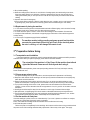
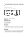
IN STRUC TION MANUA L Laboratory Equipment Pty Ltd email: [email protected] Ph: 02 9560 2811 • Fax: 02 9560 6131 www.labec.com.au 2014 USER MANUAL Low-speed Table-top Centrifuge L-450 Introduction Using Environment of Equipment In order to ensure the safety of using the machines, the centrifuge may be damaged by following factors: -Chemical effects; -Environmental impacts, including radiation of natural UV; -The corrosion and abrasion and wear of shield and other security components. * Indoor use; * Altitude: ≤2000m; * The applicable temperature range for the instrument is: +5º ~ +40º; * Relative humidity is ≤80%; * The scope of power supply for the instrument is AC240V, 50HZ/60 (marked behind machine); * Adequate ventilation should be available indoor; * There isn't any vibration or airflow around which maybe effect the performance of the instrument; * There isn't any conductive explosive dust or corrosive dust around; Safety Tips * Please read this manual carefully for the first-time using! * The maintenance of the instrument can only be done by Our Company or authorized dealers of Our Company; * Please NEVER use the following materials in the centrifuges: -Inflammable and explosive materials; -Strengthen chemical materials; -Toxic or radioactive substances or pathogenic micro-organisms and so on. * If there is any situation that not mentioned in this manual, please kindly contact Our Company or authorized dealers to ask for best way of dealing with it. * Please try to use the accessories from Our Company, and if you need use the ones from others, Our Company will not be responsible for any adverse effects caused by it. * You must do the inspection and maintenance for the Low-speed table-top centrifuge at the stated interval. Security warning signs Note: Before using this instrument, please read this manual carefully. Note: The high pressure is dangerous! Catalogue 1st Terms of safety using 1.1 Notes of Operation 4 5 2nd Introduction of Low-speed table-top centrifuge 2.1 Overview 2.2 Introduction of Equipment 2.3 Security structure 2.4 Requirement of placing the machine 5 5 6 7 8 3rd Preparation before using 3.1 Transportation and installation 3.2 Choose suitable place to place 3.3 Put the machine at fixed place 3.4 Connect the power supply in correct way 8 8 9 9 9 4th Operating instructions 4.1 Introduction of control panel and display interface 4.2 Boot 4.3 Open the door 4.4 Close the door 4.5 Installation of the rotor 4.6 calculation of rotor load 4.7 Filling of sample in the centrifuge 4.8 Use the rotor in safe way 4.9 Example of operating of parameter setting 10 10 10 11 11 11 12 12 13 13 5th Items of maintenance 5.1 Cleansing and purification 5.2 Maintenance responsible by Our company 15 15 16 6th Fault Handling 6.1 Open the cover in case of emergencies 6.2 Alarm Information of fault 18 18 18 7th Packing list 22 8th Certificate 23 Appendix 1 Type of rotor and technical parameters Appendix 2 Technical Data 24 25 1st. Terms of safety using User’s better use it in accordance with the design of it; it may result in equipment damage or personal injury if there is any incorrect or inappropriate way when using the machine: ● Not used in accordance with design requirements; ● Operators and maintainers use it without training; ● Users change the contents of the design without authorization; ● Users don't pay attention or understand the rules of safe-using. Every people who involving the use or maintenance of Low-speed centrifuge should read and understand the using way and rules of safe-using of this manual. You must totally enforce the following rules to avoid accidences: The "Manual" is part of accessories of “Low-speed table-top centrifuge”, it must be put together with the machine for the operator to check. Low-speed centrifuge of general air-cooled is designed for clinical medicine, biology, chemistry, genetic engineering, immunology and so on. The density of the separated sample can not exceed 1.2g/cm ³ under the maximum speed, when the density of the sample exceeds 1.2g/cm ³, the maximum speed of the rotor must be reduced accordingly. When Low-speed centrifuge is running (separating the sample or the rotor is rotating), please make sure that nobody or any hazardous materials can be existed within 30cm away from centrifuge, and no materials block the vent of the centrifuge. The centrifuge will injure the operator or other staff or there's damage on the centrifuge and separated sample inside if the user don't follow the following safety measures when operating the Low-speed Table-top centrifuge: ● The centrifuge can't be used in the environment of corrosion or there is possibility of explosion because the design of the centrifuge is neither anti-corrosion, nor is anti-explosion (proof); ● Do not use following materials in the centrifuge: - Flammable and explosive materials; - Strong chemical materials; - Toxic or radioactive. ● For the separation of corrosive substances and pathogenic micro-organisms cells, please take effective measures of seal in advance, and do the sterilization in time after separation. For more details, please check from "issues of repair and maintenance". ● The internal part of the centrifuge will be damaged and the mechanical strength of the rotor will be weaken when using it for separating corrosive materials. In this case, corrosive materials should be put in the protective container. 1.1 Notes of operation ● Please ensure that proper rotor are installed tighten before the running of the centrifuge (separating the samples) ● Don't open the door manually if the centrifuge is still running (rotor is turning) or the rotors don't stop to turn. ● The accessories of Low-speed centrifuge should be provided by Our company. For some general accessories, such as glass and plastic containers used for the separation should be confirmed to meet the requirements. It shall conform to requirement of the use of maximum turning speed and maximum centrifugal force of the corresponding rotor. ● Do not use centrifuges or separate the sample with the door is open. ● The replacement of mechanical accessories and electronic device of centrifuge should be implemented by designated person of Our company. ● When operators are using the centrifuge, they shall choose rotor with appropriate load and shall not use the rotor overload; ● Check rotor regularly. Stop to use it once there is obvious corrosion or obvious damaged signs on the rotor; ● After a period of using, Please do the maintenance according to the rules of "cleansing and disinfection". 2nd Introduction of Low-speed centrifuge 2.1 Overview Low-speed table-top centrifuge can be widely used in fields of clinical medical, biology, chemistry, genetic engineering, and immunology and so on. It is the conventional device for centrifugation and sedimentation in the laboratory. 2.2 Profile of the structure of the device This equipment is consisting of portal system, chamber system, drive system, rotor system, engine bed, power supply system, control systems, display systems and alarm systems. 2.2.1 Portal system includes Door cover, door hinge, air spring, door lock, door alarm, Cord for emergency locks etc. The door hinge is behind the rack. The door lock is in front of rack and only in the case of that the door lock is locked tighten, you can start the centrifuge, or the door alarm system will work (BUZZ Sounds) and the machine don't work. If you want to open the door cover, just press “DOOR/STOP” key on the control panel. When the door cover opens to certain height, gas spring can support the door cover. If the power fails or the “DOOR/STOP” key doesn't work, but the samples should be removed in time, then you need special tools to get the cord pry with which connects a rope to car lock. Pull it manually please and then you can open the door cover. When the rotors of the device is turning or the power supply is on, Don't open the door cover manually ! 2.2.2 Cavity system can provide a stable working environment. 2.2.3 This equipment is using DC direct brushless motor which can drive rotor of sample with load. Driving system adopts cone-connection to make high quality of fit between rotor and rotor shaft and runs smoothly. 2.2.4 Rotor system consists of Angle rotors and Swing-out Rotor (Check "types of rotors and technical parameters") and centrifuge test-tube. The role of rotor is to load the sample and rotate with certain speed to make a relative centrifugal force field, and to achieve the purpose of separation of the samples. As the centrifuge which is caused by the high-speed of the rotor is thousands of times more than the Earth's gravitational accelerationg, it's important to use the machine safety and do the maintenance carefully. 2.2.5 Engine bed consists of rack, protective steel ring, backplane, fuselage shell and rubber support-leg, 2.2.6 Power Supply System includes power outlet and switch, and it's responsible for the supply of Utility Power required by the machine. 2.2.7 Control System includes the setting of the speed, centrifugal force, operation time, the choice of lifting speed, display system of complete machine, control or alarm system and so on. In order to ensure the normal operation of the machine and the operator's safety, please do not open front electrical enclosures of the device. 2.2.8 Display System consists of display panel and PVC keyboard panel ( control panel ). It's medium of human-computer dialogue. It can display the parameters of settings simultaneously, trace and display actual changes in the parameters. In addition, it can show various of failures and alarm. 2.2.9 Alarm system includes over speed alarm and alarm of fault of door cover. when the machine is over speed, or there is problem with opening the door cover, the system will give an alarm, at this time, the red light of the control panel will flash and buzzer will buzz, the machine can't start (not allow to start ). And the running machine will stop working automatically and it can't restart until troubleshooting. P.S: If you want to erasure the sound of the buzzer, please press ENTER key of the control panel. 2.3 Security structure ● The rack and protective steel ring are made of steel plates. The internal cavity is made of stainless steel inner container. Front frame is made of plastic. ● The structure of the door cover is explosion-proof, and there is viewing port in the middle of the top of door cover, and there is locking mechanism in the front of the door cover. Until the centrifuge is electrified and the rotor stops, you can press “DOOR/STOP” key of the control panel to open the door of the centrifuge. Only in the case of that the door cover of the centrifuge is locked, you can start the machine! ● Stop it while speeding. ● When the rotating speed of the rotor is over 250r/min of setting speed, the machine will give an alarm; When the rotating speed is over 300r/min of maximum rated speed of the rotor, the rotor will stop to rotating automatically and you can open the door until the rotor stops totally. And restart it after trouble clearing. ● Open the door when it's emergency If there is power failure suddenly or there is trouble when the rotor is rotating, and you can't open the door by pressing keys, please open the door manually (please check troubleshooting for more details) 2.4 Requirement of placing the machine 2.4.1 The device should be placed in horizontal table-board with sufficient rigidity, and it should be far away from vibration shock device. Keep it away from heat and direct sunshine. 2.4.2 There should be space of 10cm to 15cm around the centrifuge for the ventilation of the machine. 2.4.3 Adjust it after installation, and make the 4 supporting legs of the bottom of the machine support the machine evenly. 2.4.4 The scope of equipment supply AC220V 50HZ/60HZ. The machine must be totally grounding and power ground lead should be connected to ground lead of electricity grid. Don't cut the electricity when the rotor is running, or it will damage the control circuit. 3rd Preparation before Using 3.1 Transportation and installation Low-speed centrifuge of general air-cooled is transported with packing container with buffer protective materials inside. When you open the package, please remove the buffer materials. The net weight of the machine is 15 kg. Please lift the machine from left and right sides balanced. Please move it vertically and don't swing it. For long-distance transportation, please use special packing chest and fix it firmly and keep it vertically. Please handle with care. 3.2 Choose proper place to place Low-speed centrifuge can only be used indoors, and the requirement for placement is as following: ● Keep 30cm safe distance for the centrifuge, and don't put any hazardous substances or let anybody stay within 30cm around the machine. ● Please fix the bracket of the machine and don't swag. If you are using removable brackets or trolley, please ensure that there is locking device for the brackets or trolley for the safe-using of the centrifuge. ● If you put the centrifuge in the wall or corner, please make sure there distance from the wall to the posterior is 10cm and from the wall to the left and right sides is 15cm, It's good for air circulation and heat elimination. ● Centrifuge should be keep far away from the windows to avoid origin of heat and direct sunlight. ● After placement, 4 supporting legs of it should sustain on the table-board evenly and adjust the level. ● The environmental temperature for the room keeping the centrifuge should be between 5º~40º, and the environmental humidity should be ≤80%. Please keep the environment clean. 3.3 Put the machine at fixed place Once the centrifuge is placed, don't move it discretionarily. If you move it, please re-confirmed or re-adjust, and make the 4 supporting legs sustain evenly on the tableboard, ensure that the mounting bracket and the table-board are fixed and don't swag. 3.4 Connect the power correctly Please use power cord separately for the centrifuge. And make sure of that the cord is grounded well and the power cords of the centrifuge meet the safety requirement of the country or the region. The supply voltage and supply frequency should meet the requirements of this manual or the specifications of mark of the centrifuge. Please use the power cord attached with the machine, connect to electric outlet correctly and connect to main power supply fixed. When the switch of power supply is closed, it's: “︱”;and when it's switch off, it's “O”. 4th Operating instructions 4.1 Introduction of control panel and display interface SPEED RCF TI M E 4000 10 SPEED SHORT ENTER TI M E RCF START DOOR STOP Figure5: schematic drawing of control panel Introduction of Figure 5,Function of control display panel: ▲:Move up button ▼:Move down button ENTER:Confirm the Enter button DOOR/STOP:Open / stop button START:Start button RCF: Relative centrifugal force TIME: Centrifugation time setting button SHORT: Centrifugal button moments SPEED: Speed setting button SPEED/RCF: Speed / centrifugal force display TIME: Time display 4.2 Start the machine Connect one side of the power cord which is attached with the machine to the power outlet of posterior of the left side of the machine; and connect another side to mains supply which should be separate outlet. Power range of this device is AC220V 50Hz/60Hz. After connection, switch on the bottom left of the right side of the machine. After a short buzz of the buzzer, the red light on the control panel will be on. It will enter display of main interface after self-examination. Then we can do next step. 4.3 Open the door Press “DOOR/STOP “button of the control panel and the door cover will eject automatically to a certain height, and then you need lift the cover to open the door completely. You will see the cavity of the centrifuge. You can remove the rotor and package for the first-using of the new machine. Note: While opening, the door cover will spring to certain height automatically, please prevent your head or any thing else from the upward side of the door cover to avoid dangers! If it goes wrong and door cover can't open automatically, but you have to remove the materials out from the cavity, you can open the door manually. Please check “troubleshooting” for more details. 4.4 Close the door Press the door cover until door hook of front upper of door cover hooks the lock dowel and you can hear sound like "crack" twice. The bottom of door hook will touch the over travel-limit switch and then the door is locked. Please press the door cover properly. Don't overexert, or the hook will be damaged. 4.5 Installing the rotor The rotors should be confirmed and designated by our company, otherwise it may cause problem. The list of types of rotors designated by our company is attached in this manual. We suggest users using the designated rotors of this manual. (Please check "rotor type and technical parameters" for more details) Inappropriate type of rotors and centrifuge tubes will lead to poor effect, or even the damage of the centrifuge. Steps to install the rotor is as following (indicated in Figure 5): ● Switch on and wait until finish the self-examination. ● Press“ DOOR/STOP” button, and open the door cover and make sure the cleaning and non-foreign body of the cavity ● Clean the surface of the motor spindle. ● Prepare the rotor you will need, hold the rotor in hand, aim the Rotor central bore at the motor spindle, lower vertically until it reaches the bottom of the cone. Let your hands go and press the rotor downward. ● Please use tool to disassembly the rotor, just tighten up the locknut in a direction of clockwise. 4.6 Calculation of rotor load ● Calculation of maximum rotor load There is huge centrifugal force when the Low-speed table-top centrifuge is running with high-speed. The design of each rotor requires sufficient mechanical strength under maximum rated speed. That is "safety factor ", however, this "safety factor" requires that the load of the rotor shouldn't exceed its maximum rated load. If you are separating the sample, please put the sample into the container and then put them into rotor. If the sum of sample and container exceed the maximum rated load of the rotor, you shall reduce the weight of the sample or calculate the allowed-speed of the rotor (NPERM) to make sure that the load of the rotor won't exceed its maximum rated load. The calculating way of allowed-speed of rotor is as following: NPERM=Nmax×(maximum permissible load÷actual load)×0.5 Nmax:Maximum rated speed Don't use the rotor overload, or it will cause explosion of the rotor and the debris will damage the centrifuge. 4.7 Filling of sample in the centrifuge Please carefully examine that whether the centrifuge container using (centrifuge tubes, etc.)is consistent with its rated maximum allowed acceleration (centrifugal force), if possible, please lower the speed. When the centrifuge is running, if the balance performance is better, the separated area of the separating samples won't interface with each other because of the vibration, and then the effect of centrifuge will be better. Please try to keep balance when filling centrifuge with samples to get good effect of balance during running. Choose proper container for placing samples please. Please note the using life of the centrifugal container. Check whether the centrifugal container (plastic, glass) is damaged or not when it's under maximum allowed load and maximum allowed speed. If there's anything damaged, please replace in time. 4.8 Use the rotor in safe way 4.8.1 Fill samples and place the test-tubes exactly and symmetrically before the running of rotor. 4.8.2 Angle rotor shouldn't run in the critical speed area of 800r/min for long time, otherwise the big vibration caused by the machine will impact using life. 4.8.3 When replacing rotors, loose the locknut anti-clockwise with the wrench attached, and then you can replace rotor. Don't start the machine before the screw is tighten on the shaft. 4.8.4 If you need use the centrifuge repeatedly, please check whether the rotor locknut loose or not after several times. If the locknut is loose, you must tighten the screw and then start the machine 4.8.5 The centrifuge tubes can load the samples at different time but it must be symmetric loading of samples (the weight of error allowed ≤ 1.5g). Start the machine with asymmetric loading is not allowed! 4.9 Example of operating of parameter setting 4.9.1 The operation is as following if the rotor is No. 0001: power on→switch on the right side of the device, and at this time the control panel will light on. Setting the parameters as following: Rotor No. 1 Speed r/min 4000 Time: min/sec. 10 4.9.3 Setting of speed: Press the SPEED button→make the number flash on the SPEED →Press the ▲ ▼button to set the speed 4000. 4.9.4 Time setting: Press the TIME button→make the number flash on the TIME →Press ▲ ▼button to set the time 10. 4.9.5Setting RCF: Press RCF button→SPEED / RCF value is displayed as the centrifugal force →Press the ▲ ▼button to set. Just set a centrifugal force or speed can be. 4.9.6 During the process of setting parameters, if there is alarm caused by machine fault or incorrect setting on the parameters, press the ENTER stop key to cancel the alarm. 4.9.7 Press the START key, the machine will begin to run (if you need stop it halfway, please press DOOR/STOP key), time setting will reduce from set value to zero, when it shows zero, the centrifuge will stop working. And at this time, the speed will reduce from set value to zero (the time for speed reduce from set value to zero has nothing to do with the setting of speed down) when the speed is zero, the door cover will open automatically and the machine will buzz for 5 times, please press the ENTER key to stop the buzz and centrifugal process is completed. 4.9.8 If you need short time centrifugal, please press start key SHORT for long time, and the speed will increase gradually. It will stop when you release and the maximum speed is the setting speed of the rotor. 4.9.9 The machine speed is stable, can be modify the speed / centrifugal force and time parameters, Press ENTER key to set the parameters to confirm. Note: ● Install the rotor on the shaft correctly before setting parameters on the control panel. ● You can reset the parameters if the operation of parameters-setting is wrong. 4.9.10 About calculation of the centrifugal force Relative centrifugal force is usually thousands of times of gravity (g). It's unit items to measure the efficiency of variety of instrument separation or precipitation. The calculation of centrifugal force has something to do with centrifugal speed and centrifugal radius. It's based on the following equation: 5th Items of Maintenance 5.1 Cleansing and purification If the hazardous materials spill out or into the device, users have the responsibility to do appropriate purification. Users should do the cleansing and purification according to the manual to ensure no damage to the machine. If you use inappropriate cleaning agents or wrong steps to do disinfection, it maybe leads to damage of the centrifuge or internal components. 5.1.1 Steps to do cleansing and purification. Please turn off the power switch and unplug the power cord before the doing cleaning or maintenance of the centrifuge. The contents of regular (or according to using situation ) cleaning and maintenance is for the shell of centrifuge, cavity, rotor, container used for separation etc. It's for preventing contaminants left and corrosion caused by used components and environmental pollution. Don't use organic solvents because it can break down lubricants inside the motor bearing. During the process of cleaning, don't exposure liquid especially organic solvents to motor bearing spindle and bearing ball inside. 5.1.2 The implementation of steam sterilizer The life of components has something to do with times of sterilization. If there are obvious signs of corrosion or damage on the rotor or container of separation, please stop to use immediately. Table 2: Table of sterilization parameters 5.1.3 Accessories Glass tube PC tube PP tube PA tube Maximum temperature( ) 134—138 115—118 115—118 115—118 Minimum Time(min) Maximum Time(min) Maximum frequency 3 30 30 30 5 40 40 40 — 20 30 20 Maintenance 5.1.3.1 Don't collide the rotor with sharp objects. Prevent bumping during moving and disassembling. Prevent scratches caused by cracks of rotor during using. 5.1.3.2 Check the rotor components regularly (especially the test-tube bottom). Check whether there are corrosion spots, grooves or small cracks. If you find any situation as above, please stop to use the rotor and contact our company. For the demolition of the rotor, please grasp the rotor and lift it vertically. Don't swing or shake. 5.1.3.3 Usually, rotor should be cleaned once a week. For separating salts or corrosive samples, please clean immediately after using. If the sample spills out or drip in the rotor, please blot it and do partial cleaning. 5.1.3.4 Please wash the rotor with sponge or cotton bedewed with the neutral detergent, wash off the neutral detergent with distilled water. Don't sprinkle or spray water on the rotor. Because the stay of liquid will result in corrosion. To bottom up and dry is allowed after cleaning. 5.1.3.5 Remove the fragment out from centrifugal room with rags or tweezers. 5.1.3.6 Please paint the grease on the spindle motor and connect part between rotor and axle hole. 5.1.3.7 Please cut off the power and unplug the power connected to the backside of the machine before removing the front shell of the machine. Power operation is not allowed. Prevent electric shock to any people or damage of the machine. Note: This operation can only be done by specially trained maintainer from our company. 5.1.3.8 Only accessories provided by our company can be used for this machine. 5.1.3.9 Please cut off the power when you needn't use the centrifuge. 5.1.3.10 The machine is a precision instrument and please keeps it away from moisture, shock, traverse or rewind. Fragile Upward Moisture-proof Figure 7: Terms of transportation and storage 5.2 Maintenance responsible by our company. low-speed table-top centrifuge made by our company will be maintenance once a year by special maintainer from our company. And the content of maintenance is as following: l Examination of electrical part.(Examination of internal circuit functions) l Examination of stability of the resettlement of the centrifuge. l Examination of electromagnetic locks and other security circuits. l Examination of rotor locking device and spindle motor (driveshaft) l Maintenance staff clean the rotor and check the performance. l our company will charge when they provide on-site repair & maintenance service. Details of charging amount will be told on the sales contract by both parties. On the process of maintenance, if we find parts need to be replaced, it will be free of charge if in the warranty period. Otherwise it will be charged. 6th Troubleshooting 6.1 Open the cover in case of emergencies In the process of normal usage, sometimes there's accidental power failure or fail to open the door, you can't open the door but you have to remove the samples, in this case, you can open the door cover manually, and remove the sample. Note: This way can be only used for emergencies. Don’t use it as you like. When there is power failure, it will take long time to let the rotor stop totally because rotor hasn't break function when it stops to run. Please wait patiently. Steps to open the door for emergencies: 6.1.1 Make sure that the rotor stops completely (You can observe that from observe hole of top of door cover) 6.1.2 Cut off the electricity. 6.1.3 There is a plastic plug under the bottom plate of the foreside of the machine; you can pull out the plug with knife or screwdriver. And there is a rope behind the plastic plug, once you pull the rope, the door cover can be open, and then you can remove the centrifugal samples out from the machine. 6.1.4 You must put the rope back in the machine and put the plastic plug back to original position after you open the door cover. 6.2 Information of trouble alarm The table shows the alarm information of the machine and the reason as well as the way to solve; you can rule it out according to the table. IF users still can't solve the problem or the alarm information is not included, please contact maintainer from our company immediately. Please turn off the electricity first when there is any problem. And start it until the problem is solved. Table 3: Data of trouble alarm Symbols Information of abnormal phenomenon E2 Over speed. It stops to work because of detection of over speed of rotor E3 Door cover protecting E5 parameter setting is wrong E7 Fault of driving ● contact our company please E8 Parameter setting error ●Follow the parameter settings to re-set in part Troubleshooting ● Problem of microcomputer control system, please contact us. ● Problem of speed sensor. Please contact us. ● Re-close the door cover ● Please contact us if the door cover is broken ● Please re-set according to content of parameter setting Table 4: Fault phenomenon, causes and troubleshooting Fault phenomenon No display Stop to work suddenly Causes and Troubleshooting 1. Check whether the power outlet and the connection is ok; is the power supply on.. 2. Whether the switch is ok. 3. If you can't solve it, please contact staff of our company. 1. The speed extends the maximum rated speed of the rotor. 2. Once the speed of the rotor extends rated speed of 250r/mi, the alarm of over speed will work. Then, You should wait until the machine stops and reset the speed. 3. The speed extends setting speed of the rotor. 4. If the motor is overheating, power supply will be cut inside the machine, and then the machine will stop working. 5. If there isn't any display on the keyboard panel, please check the power supply system of the machine. 6. Maybe the voltage is low; please check whether the voltage of the power supply is ok. Door can’t open 1. The door can't open until the rotor finishes stopping turning. 2. Check the assembly of the door lock. 3. Check the electrical wires of the door lock. 4. Open the door manually. 5. If you can't solve it, please contact staff of our company. Vibration of machine is a bit heavy 1. The following situation is normal: The speed of rotor is over the critical speed and the machine vibrates. 2. Check whether the rotor is locked tightens or not. 3. Check the symmetry of the load of the rotor; check the working situation of the machine. 4. Check whether the rotor is installed correctly. 5. Check the shaft: rotate it with hand and if it can't rotate smoothly, then maybe there's problem with shaft or motor. If you can't solve it, please contact staff of our company. Indicator light of panel LED isn’t up after switch on. 1. Power supply is not connected, please check the power. 2. The fuse of PCB board and power outlet is broken; please ask professional staff change the fuse. 3. If you can't solve it, please contact staff of our company. Unusual display of operating panel 1. Maybe it's because of the interference of power grid, please shut down and starts it after 1 minute, and then the display will be ok. The motor doesn’t work after pressing start key 1. Electric control circuit is broken. Please change the electric control board. Smell of burnt from the machine 1. Cut off the power. 2. whether the motor is burnt 3.whether the electrical components are burnt 4. Rotate the driving shaft with hand, if it can't drive smoothly, please contact professional staff of manufacturer to solve it. Not the problems above 1. Please contact the professional staff of manufacturer to solve. 7th Packing List Packing list of Low-speed centrifuge of general air-cooled Number 1 2 3 4 Name low-speed table-top centrifuge power cord Angle rotor 24×15ml English service manual Qty 1set 1pc 1pc 1pc Note When you open the package, please check in time, if there's anything wrong, please kindly contact our company or authorized dealers in time. 8th Certificate of Compliance Low-speed table-top centrifuge L-450 Certificate of Compliance Maximum rotate speed: 4000r/min Maximum relative centrifugal force: 2010×g Factory Number: This product is qualified after examination. It can be sold in the market. Inspection Date: Appendix 1 Optional Accessories If you need buy the optional auxiliary parts, please contact and ask manufacturer or our company or authorized dealers. Function/ Parameter Technical Data Ambient Temperature ● House supply ● There isn't any vibration or airflow around which maybe effect the performance of the instrument. There isn't any conductive explosive dust or corrosive dust around ● Altitude: ≤2000m ● Relative humidity: ≤80% ● +5ºC ~ +40ºC Applicable voltage ● AC240V 50HZ/60HZ Setting Time range ● 0~99min, Maximum RPM ● 4000 r/min Environment of Use Maximum relative centrifugal force Maximum capacity ● 2010×g ● 24×15ml Climbing Speed ● Lowering Speed ● Noise (maximum speed) ● ≤62dB(A) Dimensions (machine) ● 500 ㎜(L)*400 ㎜(W)*310 ㎜(H) Net Weight ● 18 ㎏ Dimensions (package) ● 675 ㎜(L)*560 ㎜(W)*490 ㎜(H) Gross Weight ● 20 ㎏ Appendix 2 Technical data Rotor No. (Rotor) Capacity (tubes × ml) Maximum speed (r/min) Maximum relative centrifugal force(×g) #01 Angle rotor 18×5ml 4000 2220 #02 Angle rotor 18×10ml 4000 2220 #03 Angle rotor 24×15ml 4000 2220 #04 Angle rotor 12×20ml 4000 2220 #05 swing-out rotor 8×15ml 4000 2510