1
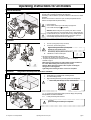
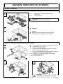
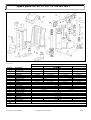
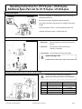
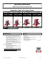
Operating Instructions Read it before commencement please Version 1.5 from 108.08.07 Hydraulic Jacks JH G-plus Series JH 5 G-plus LxWxH Weight Capacity Lifting height Workingpress. mm kg kg mm bar 311x233x280 23 5500 140 520 JH 10 G-plus LxWxH Weight Capacity Lifting height Workingpress. mm kg kg mm bar 330x247x310 29 10000 150 520 JH 15 G-plus LxWxH Weight Capacity Lifting height Workingpress. mm kg kg mm bar 415x300x310 48 15000 175 520 JH 20 G-plus LxWxH Weight Capacity Lifting height Workingpress. mm kg kg mm bar 435x330x340 60 20000 190 520 = with slide shoe guiding Recommended Use Contents These jacks are designed specifically for lifting heavy loads vertically. They should only be used on solid level ground. Do not use on a slope. The load must have a suitable strong pick-up point which will accept the full surface of the lifting toe. The centre of gravity must be in the under half of the load Do not exceed the maximum load recommended in this document and shown on the identification plate on the jack. Always lower the jack slowly and carefully. Otherwise the guide of the housing may be damaged due to high friction forces. Every other use than recommended must be avoid. The manufacturer or supplier is not liable for any damage resulting from improper use of the jack. Accidences resulting from improper use are the responsibility of the user. These products are not designed: For lifting and moving people or mobile devices. For use in extreme environment (i.e. under hazardous, explosive, flammable or corrosive conditions) Materials and lubricants used may not meet local food and agricultural industry regulations The user should read these operating and service instructions carefully before attempting to use the jacks. Particular attention should be paid to the safety instructions on page 8. © Jung Hebe- und Transporttechnik Technical Data…..…………………………………………………… 1 Appointed application.................................................................... 1 General information, service instruction for all models…………… 2-3 Maintenance, assembly, repair…..………………………………… 4-5 Spare parts for all models….………………………………………… 6 Operating hints and additional spare parts for fast lift unit ………. 7 Special hints, Safety instructions……………………………………. 8 CE, Declaration of Conformity………………………………… See Enclosure Operating Instruction JH G plus Page 1 Operating instructions for all models General Information In purchasing the JUNG jack, you have made a wise decision. This small power package makes your lifting and transport jobs child’s play. The drawing on the left illustrates a possible combination for the ideal use of JUNG equipment. All units can be stored in a minimum of space, are easily transportable and are therefore an indispensable help when travelling. A Recommendation: Work in tandem with two jacks when lifting very large loads. Use a JUNG central pump ( in picture A). Attention: When working with two hydraulic jacks, fitted to a central pump, please note that is only one hydraulic circuit i.e. the hydraulic fluid can flow between the jacks. The jacks should be very carefully positioned under the load, keeping in mind the location of the centre of gravity to ensure stability and prevent the load from tipping over. Operation 1. 2. B Lift loads. zwe (moving pump lever up and down) Lower loads. (loosen lowering screw) Retighten lowering screw when job completed! Otherwise the next load will not lift. 3. 4. Fitted in this way, the pump lever can be used as a handle bar for castor-mounted jacks The following description applies to the models: JH 5 G plus, JH 10 G plus, JH 15 G plus, JH 20 G plus. The special operational features of Model JH 15 G plus, JH 20 G plus is described on page 7. Before starting to work pull the pin of the breather screw for ventilation of the oil tank. After finishing work close the pin (see picture) Attention: When lowering the goods too fast oil sputter could happen. Lifting speed = Lowering speed! Light leakage when lowering too fast is no reason for complains! Variation 1 The goods to be transported have floor clearance C 1. 2. 3. Insert lifting toe in suitable hole on sliding column. Fix it with holding bracket. Align swivelling feet of the jack with goods to be transported. Place the jack always on flat, solid subsoil: D 1, 2, 3 Lift rear end of load step by step (in 30 mm steps), then pushing the adjustable rear skate underneath. 4-5 Lower jack slowly and remove it. Don’t forget: Tighten lowering screw when job completed! © Jung Hebe- und Transporttechnik Operating Instruction JH G-plus page 2 Operating Instructions for all models Operation (Continuation) Variation 1 Goods to be transported have floor clearance (continuation) E Lift front of loads to be transported and push the steerable skate underneath. Lower jack and remove it. 6, 7, 8 9, 10 Don’t forget: Tighten lowering screw when job is completed! F Transport Attention: Transport only on flat and solid subsoil; when using a tractor vehicle the tensile force and brake force must be attended. Variation 2 Goods to be transported have no floor clearance. G H Place the lifting toe of your jack under a suitable place of the loads to be transported. ( e.g. Picture G) 1 Swivel feet of the jack to the side 2, 3 Lift loads to be transported slightly and insert a strong packing piece underneath (e.g. steel, hardwood). 4, 5 Now you can place the lifting toe under the loads to be transported and swivel the feet of the jack underneath the load. 6, 7, 8 Lift loads more, remove the packing and drive the steerable carriage underneath the load. 9, 10 Lower jack and remove it. I Don’t forget: Tighten lowering screw when job is completed! © Jung Hebe- und Transporttechnik Operating instruction JH G plus page 3 Maintenance, Assembly, Repair Maintenance We recommend a yearly maintenance of your jack (see annexed sheet). 6 6 You have purchased a very safe and reliable unit. Observing the following maintenance instruction will ensure that the jack will provide long service to your entire satisfaction. Grease guides regularly as they are exposed to high friction forces! 1, 2 Pull off bracket and remove lifting toe. 3 Lift slide lightly. 4 Loosen screw. 5 Pull out slide. 6 Oil bolt Clean guidance and slide shoes Oil bolt regularly Assembling: return steps 6 Control and renew slide shoes regularly if wear o Jacks never use: - without slide shoes - with less than 4 slide shoes - when slide shoes are worn out What to do if? FAULT CAUSE REMEDY Load is not fully 1 Lack of oil First lower lifting piston fully lifted Lifting piston not Add oil completely Oil level – see picture extended Change hydraulic oil yearly. We recommend JUNGhydraulic oil for reliable function. (Part-No. 94 040 028-E including oil change instruction) Dispose the waste hydraulic oil in accordance with environmental regulations. Load is not lifted at all 2 3 4 5 If a pump repair has to be carried out please return on consultation with us: Only the pump unit of JH 5, 10, 15, 20 G-plus The complete jack of JH 5, 10, 15, 20 G plus. We recommend a yearly maintenance of your jack by our quick service (see annexed sheet) 6 7 8 Admissible Capacity exceeded Lowering screw open Use additional or larger jack Pressure screw loose Ball seat of lowering screw not seating - Caused by foreign body Tighten it Valve dirty Valve defective Breather valve defective Tighten it Press ball in seat Tighten lowering screw cautiously several times (with pliers) Remove it, clean it Remove it, displace it Displace it If you carry out the maintenance by yourself, please dispose of your waste oil in accordance with environmental regulations. © Jung Hebe- und Transporttechnik Operating Instruction JH G plus Page 4 Maintenance, Assembly, Repair Valve Assembly remove and install 1 4 3 1. 2. 3. 4. 5. 6. 6 2 5 Then remove valve assembly 12 7 8 Pull off bracket Remove lifting toe Loosen screw Pull out slide Loosen screws on bottom plate Pull out pump unit 13 11 10 7. Lower lifting piston and loosen lowering screw 8. Loosen oil reservoir valve 9. Drain oil => Tilt unit and let oil drain in suitable container 10. Drive out transverse dowel pin 11. Unscrew hexagon nut 12. Remove pump rods 13. Loosen hexagon nut and pull out pressure piston with pressure cylinder 14. Turn unit upside down, shaking out the valve assembly 14 9 INSTALL VALVE ASSEMBLY 6 9 11 8 1 7 2 3 12 © Jung Hebe- und Transporttechnik 5 4 1. 2. 3. 4. Blow out valve seat with compressed air! Insert valve assembly with sealing ring and ball Remove copper sealing Insert pressure piston from the bottom into the pressure cylinder 5. Reinsert copper sealing 6. Insert pressure piston and pressure cylinder into the guiding pipe 7. Screw on intermediate ring and pressure screw 8. Insert pump rod, securing it by means of the nut 9. Drive in transverse dowel pin 10. Fill with oil 11. Screw in oil reservoir valve 12. Reinstall the pump unit (not pictured) Operating Instructions JH G plus.doc page 5 Spare parts for JH 5 / 10 / 15 / 20 G-Plus 1 Version 1.5 from 08.8.07 Item-No. 1 2+11-35 without 16, 29 3 4 5 4-5 6 789 10 11 12 13 14 15 16 17 23 24 25 26 27 28 29 8 9 25 27 33 34 35 Designation Housing without feet Pump unit / Tank completely Slide assy. Swivelling toe Bracket Swivelling Toe and Bracket Set Slide Shoe, 1 piece Lifting Piston assy. Guide nut Lowering Screw Swiveling Foot Pump Rod assy. Oil reservoir breather valve Wheel with circlip lock ring Handle bar assembly Valve complete Pressure Cylinder Pressure Screw assy. Pressure Piston Pump Lever Seal kit Hydraulic Nipple JUNG hydr. Oil 1 litre JH 5 G plus 1 Models JH 10 G plus 1 JH 15 G plus 1 Part-Numbers JH 20 G plus 1 91 056 251-B 91 106 251-B 91 156 251-B 91 206 251-B 91 056 450-B 91 106 450-B 91 156 450-B 91 206 450-B 91 056 300-B 91 056 525-B 91 056 515-B 91 056 550-B 91 106 300-B 91 106 525-B 91 106 515-B 91 106 550-B 91 156 300-B 91 156 525-B 91 156 515-B 91 156 550-B 91 206 300-B 91 206 525-B 91 206 515-B 91 206 550-B 91 106 435-B 91 114 043-E 91 156 435-B 91 154 043-E 91 206 435-B 91 254 043-E 91 152 411-B 91 206 210-B 91 103 420-E 91 056 435-B 91 056 243-E 91 153 020-E 91 106 446-B 91 102 411-B 91 010 004-B 94 040 086-B 95 050 086-E 91 106 260-B 95 050 087-E On request 91 010 016-B 91 010 012-B 91 010 110-B 91 106 463-B 91 106 480-B 99 066 505-L 99 060 410-L 99 066 515-L 99 060 425-L 94 040 002-E 94 040 028-E JH 5 G plus/ JH 10 G plus new version 04/2005 © Jung Hebe- und Transporttechnik Operating Instructions JH G plus.doc Page 6 Operating Instructions for JH 15 G-plus / JH 20 G-plus Additional Spare Part List for JH 15 G-plus / JH 20 G-plus General Information Load lifting quick lifting The jacks JH 15 G plus und JH 20 G plus lift heavy loads through an inbuilt hydraulic pump unit. Due to the power ratio the lifting piston raises the load slowly. A fast stroke is provided to bring the toe to the underside of the load to be lifted. Fast stroke: big piston surface => for fast toe positioning without load Load lifting: small piston surface => for lifting under load OPERATION 1. Quick lifting: Raise quick-lifting toe until it touches the bottom of the load. 2. Lift the load: Insert pump lever into the other pump rod assembly for load lifting. 3. Lower the load: Loosen lowering screw slowly and carefully. Tighten lowering screw Additional Spare Parts for JH 15 G PLUS / JH 20 G PLUS Version 1.3 from 03.05.2006 The jacks JH 15 G plus / JH 20 G plus are additionally equipped with following spare parts for quick lifting function: © Jung Hebe- und Transporttechnik Pos.-No.: Designation 13 Pump rod assembly 91 010 004-B 23 Valve complete 91 010 016-B 41-42 Pressure cylinder fast lift unit 91 206 480-B 25-26 Pressure screw assembly 91 010 110-B 43-46 Pressure cylinder fast lift unit 91 206 466-B Operating Instruction JH-G plus 1 Order-No. Page 7 Additional Notes, Safety Instructions GUARANTEE PROTECTIVE EQUIPMENT All JUNG jacks are guaranteed against materials or manufacturing faults for a period of 12 month from delivery to the customer. Unauthorised interference with the working parts of the jack during this period will invalidate this guarantee. SAFETY WORKING INSTRUCTIONS 1. Read instructions Before the jack is used, these instructions must be read in their entirety by all operating staff (i.e. all personnel who have received instructions to carry out the lifting and transport operations). 2. Communication and organisation The communication between all operating stuff must be guaranteed, especially when the visibility between each other is interrupted. One non-operating person has to be responsible for control and clear advice to all operating personnel. 3. Danger Zone The operator must ensure that other persons should remain at a safe distance of 1.5 times the height of the load (i.e. clear of the danger zone). No unauthorised person or anyone not familiar with its operation should attempt to use the jack. 4. Load and Centre of gravity The complete net weight and the position of the centre of gravity of the load have to be found out before any operation. Use of jacks and hydraulic pumps without knowing these facts is dangerous and can be lead to damaged equipment and/or damage to the load and operating personnel. The choice of an adequate jack can be done with this formula: Minimum jack capacity = (Load weight in kg) x 1. 25 (security factor) (I.e. load weight 4000 kg x 1.25 = 5000kg; the jack must have a minimum capacity of 5000 kg.) While using more than one jack with one load it is important that the jacks are placed under the load in positions where it is guaranteed that all of them will have to lift the part of the weight. Therefore the part of the load plus security factor must not exceed the capacity of the single jack. In order to place the jacks correctly as requested it is absolutely necessary to know where the position of the centre of gravity is located. Lowering the jacks without a central pump the lowering speed has to be slow and absolutely synchronised on all jacks deployed. For security purpose use of Jacks with different capacities isn’t allowed. 5. Recommended use These jacks are designed specifically for lifting heavy loads vertically. They should be used on solid level ground only. Do not use on a slope or slippery ground. The load must be stable enough for lifting on a single point and must not be tip over while lifted. The surface where the jack will be attached must be suitable for lifting referring size, stability and non-slippery. Size means that there must be enough room to lift up with the full surface of the lifting toe or top plate, only partial connection between the lifting surface of jack and load is not enough. For working with 2 or more jacks we recommend the use of a central pump when the weight of the load: 1. exceeds the capacity of one jack for more then 1.5 x or 2. the height of the load exceeds the length of the side of the load which is to be lifted. While working with more than one jack the knowledge of the centre of gravity determines the position of the jacks. (See 4 above “load and centre of gravity”). Important: If the height of the load exceeds the length of the side being lifted and/or the centre of gravity is located in the upper half of the load appropriate precautions must be taken to prevent the load from tipping. 6. Lifting and lowering: After preparing the a.m. steps the initial lifting should be done slowly and carefully. Examine the load carefully after the first few mm of lift to ensure there is no exceptional slipping or bending in the load. If this safety check is done, the lifting operation can be continued. When the jack is in the raised position under the load: No-one should attempt to work on or in the close vicinity of the load or handle under the load. The jack should not be left unattended when supported on the raised jack. No unauthorised person or anyone not familiar with its operation should attempt to use the jack. 7. Lifting height: For security reasons the load has to be lifted and lowered step by step. Steps causing more than 30 mms of height difference on one side have to be avoided. Use suitable pads, i.e. hard wood or steel to secure the load when changing the side. For your own safety do this when lifting tall loads with a high centre of gravity. All members of operating personnel must wear safety footwear with steel toecaps. SAFETY MECHANISM Each jack is fitted with a safety valve which restricts the permissible operating pressure of its internal pump to 520 bar, thus limiting the maximum load to the weight permissible for the device in question. WARNINGS When working with 2 or more hydraulic jacks and 2 or more hydraulic pumps on one load there is a danger that individual jacks could become overload and damaged if lowering is performed unevenly. This could result in the load being dropped suddenly or tipped over, creating considerable risk of personal injury to the operator as well as risking damage to the load and anything else in within the danger zone. It is of the utmost importance when working with a jack and while lowering the load, that no part of the jack other than the lowering screw is touched. When using single or multiple jacks neither the operator nor anyone else should allow any body part to enter the area beneath the load, beneath the lifting toe or close to the jack body and sliding column. When lowering the load, the toe and sliding column move in relation to the body of the jack and the floor, clothing and operator’s body parts could be trapped and personal injury result if proper caution is not exercised. GENERAL SAFETY INSTRUCTIONS For safe working it is necessary to know the local general safety regulations of your country. Furthermore you have to pay attention to the regulations depending to your branch of industry, operational area and operation purpose. Jung-Equipment is designed for use under usual atmospherically conditions and temperatures between -5° and 45° C. All operational personnel working with the JUNG equipment must be instructed regularly in safe working conditions by a security instructor or a safety expert. This must be done personally as training, delivery of written regulations or manuals and/or announcement on signs is not enough. Before each use of the jack you must check that it is in good working condition and a valid inspection badge is on the jack. If there is no badge or the jack seems obviously defective, i.e. deformations or cracks in the main housing, wear or oil leaks on moving parts, the jacks should be inspected before use and a valid control badge has to be put on. REPAIRS Any repairs which may become necessary after years of rigorous use can be carried out promptly and economically by us after supplying an estimate SERVICE At your request we will, if you so wish, carry out a fixed-price, annual service on your lifting device. Please contact us in writing or by telephone. If you require information quickly, have questions you would like answered or wish to place an order rapidly, please call us: We will be happy to provide you with any further assistance you may require. We reserve the right to make any technical modifications to improve the equipment. © Jung Hebe- und Transporttechnik Operating Instruction JH G plus.doc Page 8