1
ESIE13-02
Service Manual
Hybrid
- Gas boiler
- EHYKOMB33AA / EHYKOMB33AA
- Hydro-box
- EHYHBH05AAV3 / RHYHBH05AAV3
- EHYHBH08AAV3 / RHYHBH08AAV3
- EHYHBX08AAV3 / RHYHBX08AAV3
- Outdoor unit
- EVLQ05CAV3 / RVLQ05CAV3
- EVLQ08CAV3 / RVLQ08CAV3
ESIE13-02
1
1
Introduction
1.1
1.2
1.3
1.4
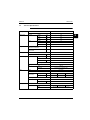
About This Manual .......................................................................................
About the Documentation ............................................................................
For the User .................................................................................................
For the Installer ............................................................................................
6
8
9
10
1.1
1.2
System Build-up...........................................................................................
Components and Connections ....................................................................
18
19
2.1
System Operation ........................................................................................
22
PCB Description ..........................................................................................
Overview Switch Box ...................................................................................
Cable Dimensions........................................................................................
Piping Diagram ............................................................................................
32
34
38
40
Part 1
System Outline
3
1
Description
4
2
Functionality
5
3
Wiring Diagrams
3.1
3.2
3.3
3.4
Part 2
Specifications
1
2
Gas Condensing Boiler
1.1
Technical Specifications ..............................................................................
42
2.1
Technical Specifications ..............................................................................
44
Hydro-box
Table of Contents
2
ESIE13-02
3
Outdoor Unit
1
3.1
3.2
Nominal Capacity and Nominal Input...........................................................
Technical Specifications ..............................................................................
46
47
Part 3
Commissioning
Part 4
Troubleshooting
3
1
4
Troubleshooting
1.1
1.2
1.3
1.4
1.5
1.6
1.7
1.8
2
54
55
75
76
79
80
83
84
Error Codes: Gas Condensing Boiler
2.1
2.2
2.3
2.4
3
General Troubleshooting Flowchart .............................................................
Overview of General Problems ....................................................................
Fault-diagnosis by Remote Controller..........................................................
Fault-diagnosis Manual Reset in the Memory..............................................
Troubleshooting by LED on the Hydro-box PCB .........................................
Overview of Error Codes..............................................................................
Overview of the Outdoor Safety Devices .....................................................
Overview of the Hydro-box Safety Devices .................................................
General Guidelines ......................................................................................
Solving Problems Based on Symptoms .......................................................
Solving Problems Based on Error Codes ....................................................
Symptoms ....................................................................................................
85
86
87
89
Error Codes: Hydro-box
3.1
3.2
3.3
3.4
3.5
3.6
3.7
“A1” Malfunctioning Hydro-box PCB ............................................................. 94
“89” Water Heat Exchanger Frozen ............................................................. 95
“CJ, C4, 81, 80, HC, H1” Thermistor or Related Abnormality (Hydro-box) .......... 96
“7H” Hydro-box: Flow Error........................................................................... 97
“C0” Hydro-box: Flow Sensor Failure ........................................................... 100
“EC” Hydro-box: Domestic Hot Water Tank Temperature too High (> 89°C) 101
Warning “AH” Tank Disinfection Function Not Completed Correctly ............ 102
3
Table of Contents
5
ESIE13-02
1
4
Error Codes: Outdoor Units
4.1
4.2
4.3
4.4
4.5
4.6
4.7
4.8
4.9
4.10
4.11
4.12
4.13
4.14
4.15
4.16
3
4.17
4.18
4.19
4
5
Error Codes: System Malfunctions
5.1
5.2
5.3
5.4
5.5
5
5.6
5.7
6
“E1” Outdoor Unit PCB Abnormality.............................................................. 103
“E3” Abnormal High Pressure (Detected by the HPS).................................. 104
“E4” Actuation of Low Pressure Sensor ....................................................... 106
“E5” Compressor Motor Lock ....................................................................... 109
“E7” Malfunction of Outdoor Unit Fan Motor................................................. 111
“E9” Malfunction of Electronic Expansion Valve........................................... 114
“F3” Malfunctioning in Discharge Pipe Temperature .................................... 117
“H3” Malfunctioning HPS System ................................................................. 119
“H9, J3, J5, J6, J7, J8” Thermistor or Related Abnormality (Outdoor Unit) .... 121
“J1” Malfunction of Pressure Sensor ............................................................ 122
“L1” Faulty Outdoor PC Board ...................................................................... 124
“L4” Radiation Fin Temperature Increased .................................................. 126
“L5” DC Output Overcurrent (Instantaneous)............................................... 128
“L8” DC Output Overcurrent (Instantaneous)............................................... 130
“L9” Stall Prevention (Time Lag) .................................................................. 132
“LC” Malfunction of Transmission System (Between Control PCB and Inverter
PCB) ...................................................................................................... 134
“P1” Open Phase or Power Supply Voltage Imbalance ................................ 136
“P4” Malfunction of Radiator Fin Temperature Thermistor........................... 137
“PJ” Malfunction of Radiator Fin Temperature Thermistor........................... 138
“U0” Gas Shortage (Malfunction) ................................................................. 139
“U2” Abnormal Power Supply Voltage.......................................................... 141
“U3” Underfloor Heating Screed Dry-out Failure .......................................... 143
“U4” Malfunction of Transmission between Hydro-box and Outdoor Unit .... 144
“UF” Malfunction of Transmission between Hydro-box and Outdoor Unit or Gas
Shortage ................................................................................................ 146
“U5” Malfunction of Transmission between Hydro-box and Remote Controller
148
“UA” Indoor-Outdoor Combination Problem ................................................. 149
Additional Checks for Troubleshooting
6.1
6.2
6.3
6.4
6.5
6.6
6.7
6.8
6.9
6.10
6.11
6.12
6.13
6.14
Table of Contents
Check No.1 - Outdoor Unit: Checking the Installation Condition ................. 150
Check No.2 - Outdoor Unit: Checking the Expansion Valve........................ 151
Check No.3 - Checking the Thermistors ...................................................... 152
Check No.4 - Resistance Conversion Table (Ambient, Coil, Fin) ................ 153
Check No.5 - Resistance Conversion Table (Discharge Pipe Sensor)........ 155
Check No.6 - Evaluation of Abnormal High Pressure .................................. 156
Check No.7 - Evaluation of Abnormal Low Pressure................................... 157
Check No.8 - Clogged Points ...................................................................... 158
Check No.10 - Outdoor Unit: Fan Speed Pulse ........................................... 159
Check No.11 - Outdoor Unit: Check for Power Transistor ........................... 160
Check No.13 - Check for Inadequate Refrigerant........................................ 161
Check No.14 - Check for Excessive Refrigerant Charging .......................... 162
Check No.15 - Check for Factors Causing Wet Operation .......................... 163
Check No.16 - Troubleshooting Yonos Para Inverter Pump (Only for EH/VB004008)........................................................................................................ 164
4
ESIE13-02
Part 5
Repair
1
1
Tips and Tricks
Part 6
Maintenance
3
1
Maintenance Schedule
1.1
Maintenance ................................................................................................ 168
4
5
5
Table of Contents
Introduction
1
3
ESIE13-02
1
Introduction
1.1
About This Manual
Target group
This service manual is intended for and should only be used by qualified engineers.
Purpose of this
manual
This service manual contains all the information you need to carry out the necessary repair and
maintenance tasks for the Daikin Altherma Hybrid.
Six parts
This service manual consists of an introduction and six parts:
4
5
Part
See page
Part 1–System Outline
17
Part 2–Specifications
41
Part 3–Commissioning
51
Part 4–Troubleshooting
53
Part 5–Repair
165
Part 6–Maintenance
167
Note
Gas
boiler
section
Heat
pump
section
Outdoor
unit
x
Manual
Contents
ECPEN13-729_Daikin Altherma
hybrid heat pump_tcm135-285966
general system
explanations
x
x
EEDEN14-729_EHYHBH-AV3_EHY
HBX-AV3_EHYKOMB-AA_LR_tcm13
5-304475
technical data book
x
x
EEDEN14-729_EVLQ-CV3_LR_tcm1
35-304456
technical data book
ECPEN13-732_Daikin Altherma
hybrid heat pump engineering
guide_tcm135-298162
engineering guide
x
x
x
AD130276-1_EHYKOMB33AA_tcm1
35-290423
CE declaration
x
x
x
4P349694-1_tcm135-290654
addendum book for
optional equipment
4PEN349693-1_2013_05_tcm135-29
0662
general safety precautions
x
x
x
4PEN349695-1_tcm135-290651
installation in a nutshell
x
x
x
6
x
x
ESIE13-02
Introduction
Gas
boiler
section
Heat
pump
section
Manual
Contents
4PEN349587-1A_2013_05_tcm135-2
90364
installation manual
4PEN353067-1_2013_07_tcm135-29
0386
installation and
operation manual
4PEN344906-1_2013_02_tcm135-29
0349
installation manual
4PEN353731_1B_2013_10_tcm135304271
field setting table
x
4PEN349588-1_2013_05_tcm135-29
0399
operation manual
x
Outdoor
unit
x
x
x
3
4
5
7
Introduction
1
1.2
1.2.1
3
ESIE13-02
About the Documentation
The original documentation is written in English. All other languages are translations.
The precautions described in this document cover very important topics, follow them carefully.
All activities described in the installation manual must be performed by an authorized installer.
Meaning of warnings and symbols
DANGER
Indicates a situation that results in death or serious injury.
DANGER: RISK OF ELECTROCUTION
Indicates a situation that could result in electrocution.
4
DANGER: RISK OF BURNING
Indicates a situation that could result in burning because of extreme hot or cold temperatures.
WARNING
Indicates a situation that could result in death or serious injury.
CAUTION
5
Indicates a situation that could result in minor or moderate injury.
NOTICE
Indicates a situation that could result in equipment or property damage.
INFORMATION
Indicates useful tips or additional information.
DANGER: RISK OF EXPLOSION
Indicates a situation that could result in explosion.
DANGER: RISK OF POISONING
Indicates a situation that could result in poisoning.
WARNING: PROTECT AGAINST FROST
Indicates a situation that could result in equipment or property damage.
8
ESIE13-02
1.3
Introduction
For the User
If you are not sure how to operate the unit, contact your installer.
The appliance is not intended for use by persons, including children, with reduced physical,
sensory or mental capabilities, or lack of experience and knowledge, unless they have been given
supervision or instruction concerning use of the appliance by a person responsible for their safety.
Children must be supervised to ensure that they do not play with the product.
CAUTION
Do NOT rinse the unit. This may cause electric shocks or fire.
3
NOTICE
Do NOT place any objects or equipment on top of the unit.
Do NOT sit, climb or stand on the unit.
Units are marked with the following symbol:
4
This means that electrical and electronic products may not be mixed with unsorted household
waste. Do NOT try to dismantle the system yourself: the dismantling of the system, treatment of
the refrigerant, of oil and of other parts must be done by an authorized installer and must comply
with applicable legislation. Units must be treated at a specialized treatment facility for reuse,
recycling and recovery. By ensuring this product is disposed of correctly, you will help to prevent
potential negative consequences for the environment and human health. For more information,
contact your installer or local authority.
Batteries are marked with the following symbol:
This means that the batteries may not be mixed with unsorted household waste. If a chemical
symbol is printed beneath the symbol, this chemical symbol means that the battery contains a
heavy metal above a certain concentration. Possible chemical symbols are: Pb: lead (>0.004%).
Waste batteries must be treated at a specialized treatment facility for reuse. By ensuring waste
batteries are disposed of correctly, you will help to prevent potential negative consequences for the
environment and human health.
9
5
Introduction
1
ESIE13-02
1.4
For the Installer
1.4.1
General
If you are not sure how to install or operate the unit, contact your dealer.
NOTICE
Improper installation or attachment of equipment or accessories could result in electric shock, short-circuit, leaks, fire or other damage to the equipment. Only use accessories, optional equipment and spare parts made or approved by Daikin.
WARNING
3
Make sure installation, testing and applied materials comply with applicable legislation (on top of the instructions described in the Daikin documentation).
CAUTION
Wear adequate personal protective equipment (protective gloves, safety glasses, ...)
when installing, maintaining or servicing the system.
WARNING
4
Tear apart and throw away plastic packaging bags so that nobody, especially children, can play with them. Possible risk: suffocation.
DANGER: RISK OF BURNING
5
Do NOT touch the refrigerant piping, water piping or internal parts during and
immediately after operation. It could be too hot or too cold. Give it time to return to
normal temperature. If you must touch it, wear protective gloves.
Do NOT touch any accidental leaking refrigerant.
NOTICE
Provide adequate measures to prevent that the unit can be used as a shelter by small
animals. Small animals that make contact with electrical parts can cause malfunctions, smoke or fire.
CAUTION
Do NOT touch the air inlet or aluminium fins of the unit.
NOTICE
Do NOT place any objects or equipment on top of the unit.
Do NOT sit, climb or stand on the unit.
In accordance with the applicable legislation, it might be necessary to provide a logbook with the
product containing at least: information on maintenance, repair work, results of tests, stand-by
periods, ...
Also, at least, following information must be provided at an accessible place at the product:
Instructions for shutting down the system in case of an emergency.
Name and address of fire department, police and hospital.
Name, address and day and night telephone numbers for obtaining service.
In Europe, EN378 provides the necessary guidance for this logbook.
10
ESIE13-02
1.4.2
Introduction
Installation site
Provide sufficient space around the unit for servicing and air circulation.
Make sure the installation site withstands the unit’s weight and vibration.
Make sure the area is well ventilated.
Make sure the unit is level.
Make sure that the floor, where the unit will be installed, is level.
Make sure walls sensitive to heat (e.g. wood) are protected by suitable insulation.
ONLY operate the gas boiler if a sufficient supply of combustion air is ensured. In case of a
concentric air/flue gas system dimensioned according to the specifications of this manual, this is
fulfilled automatically and there are no other conditions for the equipment installation room. This
method of operation applies exclusively.
This gas boiler is NOT designed for room air dependent operation.
3
Do NOT install the unit in the following places:
1.4.3
In potentially explosive atmospheres.
In places where there is machinery that emits electromagnetic waves. Electromagnetic waves may
disturb the control system, and cause malfunction of the equipment.
In places where there is a risk of fire due to the leakage of flammable gases (example: thinner or
gasoline), carbon fibre, ignitable dust.
In places where corrosive gas (example: sulphurous acid gas) is produced. Corrosion of copper
pipes or soldered parts may cause the refrigerant to leak.
In bathrooms.
In places where frost is possible. Ambient temperature around the indoor unit should be >5°C.
Refrigerant
NOTICE
Make sure refrigerant piping installation complies with applicable legislation. In
Europe, EN378 is the applicable standard.
NOTICE
Make sure the field piping and connections are not subjected to stress.
WARNING
During tests, NEVER pressurize the product with a pressure higher than the maximum allowable pressure (as indicated on the nameplate of the unit).
WARNING
Take sufficient precautions in case of refrigerant leakage. If refrigerant gas leaks,
ventilate the area immediately. Possible risks:
Excessive refrigerant concentrations in a closed room can lead to oxygen
deficiency.
Toxic gas may be produced if refrigerant gas comes into contact with fire.
WARNING
Always recover the refrigerants. Do NOT release them directly into the environment.
Use a vacuum pump to evacuate the installation.
Only use phosphoric acid deoxidised seamless copper with annealed temper grade.
11
4
5
Introduction
1
1.4.4
ESIE13-02
Brine
If applicable. See the installation manual or installer reference guide of your application for more
information.
WARNING
The selection of the brine MUST be in accordance with the applicable legislation.
WARNING
Take sufficient precautions in case of brine leakage. If brine leaks, ventilate the area
immediately and contact your local dealer.
3
1.4.5
4
Water
NOTICE
Make sure water quality complies with EU directive 98/83 EC.
Avoid damages caused by deposits and corrosion. To prevent corrosion products and deposits,
observe the applicable regulations of technology.
5
Measures for desalination, softening or hardness stabilization are necessary if the filling and top-up
water have a high total hardness (>3 mmol/l-sum of the calcium and magnesium concentrations,
calculated as calcium carbonate).
Using filling water and top-up water which does NOT meet the stated quality requirements can cause
a considerably reduced service life of the equipment. The responsibility for this is entirely that of the
user.
12
ESIE13-02
1.4.6
Introduction
Electrical
DANGER: RISK OF ELECTROCUTION
Turn OFF all power supply before removing the switch box cover, connecting
electrical wiring or touching electrical parts.
Disconnect the power supply for more than 1 minute, and measure the voltage at
the terminals of main circuit capacitors or electrical components before servicing.
The voltage MUST be less than 50 V DC before you can touch electrical
components. For the location of the terminals, see the wiring diagram.
Do NOT touch electrical components with wet hands.
Do NOT leave the unit unattended when the service cover is removed.
WARNING
If NOT factory installed, a main switch or other means for disconnection, having a
contact separation in all poles providing full disconnection under overvoltage category III condition, shall be installed in the fixed wiring.
WARNING
ONLY use copper wires.
All field wiring must be performed in accordance with the wiring diagram supplied
with the product.
NEVER squeeze bundled cables and make sure they do not come in contact with
the piping and sharp edges. Make sure no external pressure is applied to the
terminal connections.
Make sure to install earth wiring. Do NOT earth the unit to a utility pipe, surge
absorber, or telephone earth. Incomplete earth may cause electrical shock.
Make sure to use a dedicated power circuit. NEVER use a power supply shared by
another appliance.
Make sure to install the required fuses or circuit breakers.
Make sure to install an earth leakage protector. Failure to do so may cause electric
shock or fire.
When installing the earth leakage protector, make sure it is compatible with the
inverter (resistant to high frequency electric noise) to avoid unnecessary opening
of the earth leakage protector.
Install power cables at least 1 meter away from televisions or radios to prevent interference.
Depending on the radio waves, a distance of 1 meter may not be sufficient.
WARNING
After finishing the electrical work, confirm that each electrical component and
terminal inside the electrical components box is connected securely.
Make sure all covers are closed before starting up the unit.
13
3
4
5
Introduction
1
1.4.7
ESIE13-02
Gas
The gas boiler is factory set to:
The type of gas quoted on the type identification plate or on the setting type identification plate.
The quitted gas pressure.
Operate the unit ONLY with the gas type and gas pressure indicated on these type identification plates.
Installation and adaptation of the gas system MUST be conducted by:
3
Personnel qualified for this work.
In compliance with valid gas installation related guidelines.
In accordance with applicable regulations of the gas supply company.
In accordance with local and national regulations.
Boilers that use natural gas MUST be connected to a governed meter.
Boilers that use liquid petroleum gas (LPG) MUST be connected to a regulator.
4
The size of the gas supply pipe should under no circumstance be less than 22 mm.
The meter or regulator and pipe work to the meter MUST be checked preferably by the gas supplier.
This is to ensure that the equipment works good and meets the gas flow and pressure requirements.
DANGER
5
If you smell gas:
1.4.8
Call immediately your local gas supplier and your installer.
Call the suppliers's number on the side of the LPG tank (if applicable).
Turn off the emergency control valve at the meter/regulator.
Do NOT turn electrical switches ON or OFF.
Do NOT strike matches or smoke.
Put out naked flames.
Open doors and windows immediately.
Keep people away from the affected area.
Gas exhaust
Flue systems must NOT be modified or installed in any way other than as described in the fitting
instructions. Any misuses or unauthorized modifications to the appliance, flue or associated
components and systems could invalidate the warranty. The manufacturer accepts no liability arising
from any such actions, excluding statutory rights.
It is NOT allowed to combine flue system parts purchased from different suppliers.
14
ESIE13-02
1.4.9
Introduction
Local legislation
Local regulations
for UK
It is law that all gas appliances are installed by a gas safe registered competent engineer and in
accordance with the following recommendations:
Current Gas Safety (Installation and Use) Regulations.
All current building regulations.
Building Standards (Scotland) Consolidated.
This appliance MUST be installed in accordance with the Gas (Safety and Use) Regulations,
current Building Regulations, Building Standards (Scotland), I.S.813 Installation of Gas Appliances
(Ireland), IEE Wiring Regulations (BS 7671), Health and Safety Document No. 635 (Electricity at
Work Regulations) and Local Water Authority Bye Laws.
UK Water Regulations and Bye Laws.
Health & Safety.
3
The installation MUST comply with the following British Standards codes of practice:
BS 5440: Flues and Ventilation for gas appliances of rated input NOT exceeding 70 kW (Part 1
Flues).
BS 5440: Flues and Ventilation for gas appliances of rated input NOT exceeding 70 kW (Part 2 Air
Supply).
BS 5546: 2000 Installation of gas hot water supplies for domestic purposes.
BS 5549: 1990 Forced circulation hot water systems.
BS 6700: 1997 Design, Installation, testing and maintenance of services supplying hot water.
BS 6798: 2000 Specification for installation of gas fired hot water boilers of rated input NOT
exceeding 70 kW.
BS 6891: 1998 Installation of low pressure gas pipe-work installation up to 35 mm (RI).
BS 7593: 1992 Code of practice for treatment of water in heating systems.
BS 7671: 2001 Requirements for electrical installations, IEE Wiring regulations.
BS7074:1: Code of practice for domestic and hot water supply.
EN12828: Central heating for domestic premises.
Potable water: all seals, joints and compounds (including flux and solder) and components used as
part of the secondary domestic water system MUST be approved by WRAS.
15
4
5
Introduction
ESIE13-02
1
3
4
5
16
ESIE13-02
Part 1 14
System Outline
What is in this part?
This part contains the following chapters:
Chapter
See page
1–Description
18
2–Functionality
22
3–Wiring Diagrams
32
3
4
5
17
Part 1 – System Outline
Description
11
ESIE13-02
1
Description
1.1
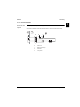
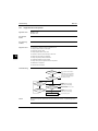
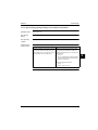
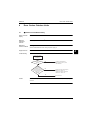
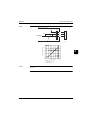
System Build-up
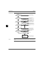
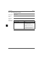
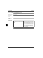
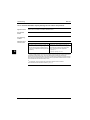
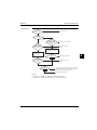
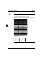
The system combines a gas condensing boiler and a heat pump (hydro-box) for space heating and
domestic hot water. Depending on the position of the 3-way valve, the gas condensing boiler can either
be bypassed or not. The heat pump can either operate or not, depending on the active operation mode
(heat pump only, gas condensing boiler only or hybrid (= heat pump and gas condensing boiler)).
HP hydro-box
3
Wall hung
condensing boiler
4
Outdoor unit
5
Part 1 – System Outline
18
ESIE13-02
Description
1.2
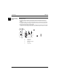
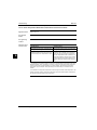
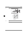
Components and Connections
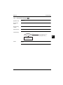
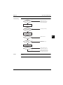
1.2.1
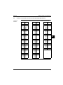
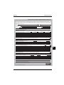
Gas condensing boiler
1
l
k
s
i
3
j
c
e
4
q
a
d
f
g
5
o
n
h
m
t
b
r
p
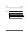
Item
Description
Item
Description
a
Gas valve
k
Air supply cap
b
Boiler control panel
l
Flue pipe adapter (use ONLY in combination
with the accompanying elbow in flue sets)
c
Sensor S1
m
Connection block/terminal strip X4
d
Sensor S2
n
Condensate drain pan
e
Fan
o
Hot water sensor S3
f
Flow sensor
p
Condensate S3
g
Space heating pressure sensor
q
Heat exchanger
h
Mains lead 230 V AC without plug
(stripped)
r
Operating panel and read-out
i
Manual air bleed
s
Ionisation/ignition electrode
j
Sight glass
t
Position of data plate
19
Part 1 – System Outline
Description
11
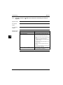
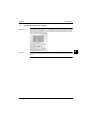
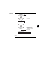
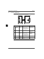
1.2.2
ESIE13-02
Hydro-box
a
g
3
b
4
f
5
Part 1 – System Outline
e
Item
Description
a
Gas in
b
Cold water in
c
Refrigerant gas connection
d
Refrigerant liquid connection
e
Heating return
f
Heating flow
g
Hot water out
20
d
c
ESIE13-02
1.2.3
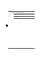
Description
Outdoor unit
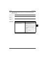
1
a
3
4
d
c
Item
Description
a
Terminal strip with earth terminal
b
Gas stop valve (ø15.9 CuT)
c
Service port
d
Liquid stop valve (ø6.4 CuT)
21
5
b
Part 1 – System Outline
Functionality
11
ESIE13-02
2
Functionality
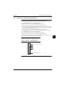
2.1
System Operation
2.1.1
Heating Mode
Heat pump only
operation
The heat pump and pump are enabled, the gas boiler is bypassed.
Space heating is enabled.
3
Allowable outdoor temperature range: -25 to 25°C.
a
4
b
5
d
e
PUMP
c
Part 1 – System Outline
a
Outdoor unit
b
Indoor unit
c
Plate heat exchanger
d
Gas boiler
e
3-way valve
22
RADIATOR
ESIE13-02
Functionality
Quick heatup
1
HEATPUMP MODE
heatpump operation
1
0
1
boiler operation at highest setpoint
0
SP+2
SP+1
set in weather dependent
SP
(or 60 C if fixed heating water temp. control) (*)
SP-1
SP-2
Time
3
4
5
23
Part 1 – System Outline
Functionality
11
Hybrid operation
mode
ESIE13-02
The heat pump, pump and gas boiler are enabled.
Space heating is enabled.
Allowable outdoor temperature range: -25 to 25°C.
a
b
d
e
3
PUMP
c
4
a
Outdoor unit
b
Indoor unit
c
Plate heat exchanger
d
Gas boiler
e
3-way valve
5
Part 1 – System Outline
24
RADIATOR
ESIE13-02
Functionality
HYBRID MODE
1
heatpump operation
1
0
boiler operation (*)
1
0
SP+2
SP+1
room temperature
SP
SP-1
SP-2
Time
3
4
5
25
Part 1 – System Outline
Functionality
11
Gas boiler only
mode
ESIE13-02
The pump and gas boiler are enabled.
Space heating is enabled. It works alternating depending on the demand of domestic hot water. If there
is a domestic hot water demand, the unit stops serving the heating and turns in domestic hot water
mode.
Allowable outdoor temperature range: max 25°C.
a
b
d
e
3
PUMP
4
c
5
Part 1 – System Outline
a
Outdoor unit
b
Indoor unit
c
Plate heat exchanger
d
Gas boiler
e
3-way valve
26
RADIATOR
ESIE13-02
2.1.2
Functionality
Domestic Hot Water
Domestic hot water
only mode
1
The heat pump and the pump are idle, the gas boiler is enabled.
Space heating is disabled. It works alternating depending on the demand of domestic hot water.
a
b
d
e
c
3
PUMP
RADIATOR
c
a
Outdoor unit
b
Indoor unit
c
Plate heat exchanger
d
Gas boiler
e
3-way valve
4
5
27
Part 1 – System Outline
Functionality
11
Domestic hot water
and space heating
mode
ESIE13-02
Depending on the mode (heat pump only / hybrid / gas boiler only) we can generate domestic hot water
and heating as follows:
During heat pump only operation, the heat pump remains operational and the gas boiler is
bypassed / domestic hot water will be generated by boiler only on demand. Both can happen
parallel.
During hybrid operation, the system will automatically switch one or both units to ON for heating
accordantly to the settings in ecological / economical / domestic hot water will be generated by
boiler only on demand. Both can happen parallel.
During gas boiler only operation, the internal pump is running and the gas boiler will serve heating
/ domestic hot water will be generated by boiler only on demand. Only one mode can be in time.
3
a
b
d
e
c
4
PUMP
c
5
Part 1 – System Outline
a
Outdoor unit
b
Indoor unit
c
Plate heat exchanger
d
Gas boiler
e
3-way valve
28
RADIATOR
ESIE13-02
Functionality
1
Return temperature below 18°C
DURING DEFROST
1
0
boiler operation
1
heatpump operation (defrosting)
0
return
temp.
hysteresis of ~ 10°C
3
25°C
Time
4
NOT DURING DEFROST : start up of heatpump mode, return <15°C
1
heatpump operation
0
18°C
5
15°C
inlet
temp.
1
boiler operation (*)
0
Time
NOT DURING DEFROST : heatpump mode, return <15°C
heatpump
1
0
1
boiler
0
18°C
15°C
Time
29
Part 1 – System Outline
Functionality
ESIE13-02
11
Economical mode, capacity shortage
heatpump
1
0
1
boiler
0
leaving
water
3
setpoint
leaving
water
leaving water will drop
below setpoint due to
capacity shortage of the
heatpump.
Time
±13 min.
4
Equilibrium point
(operation of the equilibrium point is independant of ecological or economical operation)
1
0
5
boiler
operation possible
1
boiler
operation not allowed
boiler operation
allowance
0
ambient
temp.
1
0
Time
Equilibrium point and capacity shortage
heatpump
1
0
1
boiler
0
leaving
water
setpoint
±13 min.
Part 1 – System Outline
30
Time
[ 5-01 ]
[ 5-00 ] = 1 (equilibrium enabled)
ESIE13-02
Functionality
Economic
When the heat pump operates at the break-even COP, the cost of 1kWh thermal output produced by
the heat pump is equal to the cost of 1kWh thermal output produced by the boiler. The break-even
COP is dependent on the electricity price [€/kWh], the gas price [€/kWh] and the boiler’s thermal
efficiency [%] (considered as a fixed value, independent of flow temperature, return temperature and
ambient temperature). The energy prices are set by the user or installer and can be adjusted.
Electricity price
COP Break-even, ECONO =
kWh
Gas price
Ecologic
x
boiler
kWh
When the heat pump operates at the break-even COP, the primary energy use to produce 1kWh
thermal output by the heat pump is equal to the primary energy use to produce 1kWh thermal output
by the boiler. The break-even COP is dependent on the Primary Energy coefficient (the amount of
primary energy input that is needed to generate a kWh of electricity, here assumed to be 2,5) and the
boiler’s thermal efficiency.
x
COP Break-even, ECO =
1
boiler
3
4
5
31
Part 1 – System Outline
Wiring Diagrams
11
ESIE13-02
3
Wiring Diagrams
3.1
PCB Description
3.1.1
Gas condensing boiler
3
4
5
Part 1 – System Outline
Part number
Description
a
Earth connections heat exchanger
b
Spark plug cover
c
Boiler controller
d
Earth connections boiler controller
e
Fuse (3.15 A T)
f
Gas valve and ignition unit
g
Ionisation/ignition probe
h
Main voltage
i
Fan
S1
Flow sensor
S2
Return sensor
S3
Domestic hot water sensor
S5
Flow switch
S7
Space heating water pressure sensor
X2 (1-3)
Room thermostat 230 V AC (1= Switch live, 3= Live (fused)) (not used)
X2 (1-3)
Frost thermostat 230 V AC (1= Switch live, 3= Live (fused)) (not used)
X2 (3-6)
Power supply (230 V) fan
X2 (2-4)
Mains (2= L (BRN), 4= N (BLU))
S5
Boiler communication cable
32
ESIE13-02
3.1.2
Wiring Diagrams
External connection diagram
1
3
4
5
For more details check unit wiring diagram.
33
Part 1 – System Outline
Wiring Diagrams
11
3.2
ESIE13-02
Overview Switch Box
TR1
TR2
X2M
X6Y
A4P
X1M
A1P
A8P
X5M
3
4
5
Part number
Description
A4P
Digital I/O PCB, receiver PCB (wireless ON/OFF thermostat, PC= power circuit)
(optional)
A8P
Demand PCB (optional)
TR1, TR2
Power supply transformer
A1P
Main PCB (hydro)
X*Y
Connector
X*M
Terminal strip
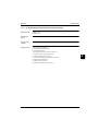
The next two figures ("PCB: part 1" and "PCB: part 2") show the wiring diagram of the hybrid PCB. The
different components are mentioned either on "PCB: part 1" or on "PCB: part 2”. The legend that is
attached mentions the description of each part number and can help to understand these two figures.
Some additional information on the PCB figures:
Part 1 – System Outline
The contacts S1S, S2S and S3S, shown on PCB PART 1, fulfil the following functions:
S1S: Preferential kWh rate: can force the outdoor heat pump to switch off.
S2S: Electric power meter pulse input (for the purpose of energy metering).
S3S: Gas meter pulse input (for the purpose of energy metering).
The user interface (A2P, see drawing "PCB: PART 1"): is delivered as an accessory within the
unit. The connection diagram (see further) shows how to connect it to the PCB.
34
13a
21
28
29
X2M
X3 X4
KFR
SS1
YC
KHR
F2U
KHUR
F1U
Y3
Y4
1 2
A3P
Space C/H
On/OFF output (*)
Y2
PHC1
3
4
5
6
CN2:1
2
only for solar option
Alarm
output (*)
Y1
CN1:1 3
A4P
(*)
Max. load
0.3 A - 250 V AC
Min. load
20 mA - 5 V DC
Only for digital I/O PCB option
Options: solar pump connection, alarm output, On/OFF output
X2M.9
X24A.5
X1 X2
KCR
ON
OFF
Digital I/O PCB
A4P
Gas pulse meter input:
5 V DC pulse detection
(voltage supplied by PCB)
Electric pulse meter input:
5 V DC pulse detection
(voltage supplied by PCB)
S3S
S2S
A2P
Preferential kWh rate PS contact:
16 V DC detection
(voltage supplied by PCB)
S1S
10
X5M
3
4
7
8
9
GAS BOILER X5
*HYKOMB*
PCB: PART 1
BSK
35
User interface
-t°
-t°
Remote
user interface
R1T
P1 P2
A2P
1 2 X5M
R1T
P1 P2
A2P
2 3 4 5 6 7 8
X18A:1 2
Switch
box
7
8
5
6
3
4
2
X40A:1
5
6
2
3
4
X33A:1
2
3
4
X39A:1
X70A:1
M
1234
Only for demand PCB option
Demand PCB
ON
OFF
DS1
A8P
Power limitation
digital inputs:
12 V DC / 12 mA detection
(voltage supplied by PCB)
1 2 3 4 5 X801M
X80A:1 2 3 4 5 6 7 8 9 10 11 12
X85A:1 2 3 4 5 6
A1P
S6S
S7S
S8S
S9S
-t°
-t°
R4T
-t°
R3T
-t°
R2T
-t°
R1T
R6T
A8P
1
2
5 6 X5M
X4A:1
2
3
X22A:1 2 4
X9A:1
2
X8A:1
2
X7A:1
2
X6A:1
2
X5A:1
2
A1P
4
4
only for instant hot water
(recirculation) without tank
-t°
R5T
only for domestic
hot water tank option
-t°
R5T
ext. ambient
sensor option
(indoor or
outdoor)
Switch box
B1L
M4S
ESIE13-02
Wiring Diagrams
1
3
Part 1 – System Outline
4
5
X2M.1
-t°
X1M
R1T R1H
-t° %H20
PC
L N
X2M.2
X2M.1
A3P
A3P
A4P
A3P
A4P
X11M 3 4 5 6
Add LWT zone
A3P
6
Heatpump convector
A3P
PC
L N
X1M
R1T R1H
-t° %H20
H C COM
only for wireless
On/OFF thermostat
6
Main LWT zone
X11M 3 4 5 6
only for ext.
sensor
(floor or
ambient)
-t°
R2T
A4P
-t°
R1T
A3P
-t°
R2T
Q1DI
only for ext.
sensor
(floor or
ambient)
only for wired On/OFF thermostat
C COM H
X2M.1a
Heatpump convector
A3P
5
X2M.4
X2M.2a
X2M.1a
X2M.4
X2M.2
H C COM
X2M.3
only for wireless
On/OFF thermostat
5
X2M.1
X2M.4
X2M.2a
only for wired On/OFF thermostat
X2M.32
X2M.3
R1T
X2M.4
X2M.4
A3P
X2M.32
C COM H
X2M.33
6
X2M.33
5
X2M.4
30 31
32
33
3
4
1a
2a
X2M
1
2
X6YB
X6Y
X2M
X2M.8
X2M.7
X1M
A1P
1
3
X14A:1
3
5
7
X24A:1
3
5
7
X2M.4
NC valve
M2S
Shut-off valve
3
3
NO valve
M2S
X2M 5 6 7
X2M.3
X2A:1 3 5
K4R
FU1
1
30 31
X2M
N
8a
NO
10
NC
9
L
M3S
only for domestic
hot water tank option
3 wire type
(SPST)
N
M3S
2
2
1
X26A:1 2
FU2
KPR
X31A:1 3
TR1
X25A:1 2 3 4 5 6 X16A:5 3
Switch box
X2M.28
A1P
X19A:1 3 5
3 wire type
(SPDT)
X2M 8
X1M
1 2 3 X1M
1 2 3
X20A:1 3 5
X6YA
X6Y
X6YB
OUTDOOR
UNIT
Only for normal power supply (standard)
Indoor unit supplied from outdoor
X17A:1 X1A:3
1 2 3 X1M
1 2 3
OUTDOOR
UNIT
X6YA
1N~, 50 Hz
230 V AC
Normal kWh rate
power supply
X2M.13a
PCB: PART 2
X2M.1a
KCR
X2M.5
KVR
L N
X2M.7
36
X2M.8
Part 1 – System Outline
3~
MS
GND
PWM
L
N
5
X2M.9
M1P
1
X2M
M
M2P 1~
34 35
E
X30A:1 3
X15A:1 3
K6R
X27A:1 2
TR2
DHW pump output
Max. load:
2 A (inrush) - 230 V AC
1 A (continuous)
11
X2M.10
3
PE
4
Only for preferential kWh rate power supply (outdoor)
Use normal kWh rate power supply for indoor unit
Wiring Diagrams
ESIE13-02
ESIE13-02
Wiring Diagrams
For the description of each part number, refer to the table below (note that the options that go together
with the hybrid are the same options as those for Altherma LT):
Part number
Description
A1P
Main PCB (hydro)
A2P
User interface PCB
A3P
*
ON/OFF thermostat
A3P
*
Heat pump convector
A3P
*
Solar pumpstation PCB
A4P
*
Digital I/O PCB
A4P
*
Receiver PCB (wireless ON/OFF thermostat, PC= power circuit)
A8P
*
Demand PCB
B1L
Flow sensor
DS1 (A8P)
*
Dipswitch
F1U, F2U
*
Fuse 5 A 250 V for digital I/O PCB (A4P)
FU1
3
Fuse T 6.3 A 250 V for main PCB (A1P)
K*R
Relay on PCB
M1P
Main water supply pump
M2P
#
Domestic hot water pump
M2S
#
2-way valve for cooling mode
4
M3S
3-way valve for floor heating / domestic hot water tank
M4S
Bypass valve gas boiler
PHC1
*
PS
Q*DI
Optocoupler input circuit
#
Earth leakage circuit breaker
Outlet water heat exchanger thermistor
R1T (A2P)
Ambient sensor user interface
*
R2T (A1P)
R2T (A4P)
5
Switching power supply
R1T (A1P)
R1T (A3P)
1
Ambient sensor ON/OFF thermostat
Outlet gas boiler thermistor
*
External sensor (floor or ambient)
R3T (A1P)
Refrigerant liquid side thermistor
R4T (A1P)
Inlet water thermistor
R5T (A1P)
*
Domestic hot water thermistor
R6T (A1P)
*
External indoor or outdoor ambient thermistor
R1H (A3P)
*
Humidity sensor
S1S
#
Preferential kWh rate PS contact
S2S
#
Electrical meter pulse input
S3S
#
Gas meter pulse input
S6S-S9S
#
Digital power limitation inputs
SS1 (A4P)
*
Selector switch
TR1, TR2
Power supply transformer
X*M
Terminal strip
X*Y
Connector
*: optional
#: field supply
37
Part 1 – System Outline
Part 1 – System Outline
all Hybrid Types
HPU Hybrid 5 kw
HPU Hybrid 8 kw H
HPU Hybrid 8 kw H/K
Nominal
capacity
4
8
8
X
X
X
230 V
Voltage
3G 1,5
(≤35m)
38
Cable type
4 G 1,5
Voltage
230 V
16 A (B)
Fuse
230 V
Voltage
G 3 1,5
Cable type
[5]
cable to 3 port valve
3G2,5
(≤35m)
Cable type
[4]
Cable between indoor
unit and outdoor unit
2A
Current
[1] Supply line to the indoor unit
when HT/NT/EVU [7] is connected
18 A
Current
Cable type
3 G 1,5
Voltage
230 V
Cable type
3 G 1,5
Cable type
2 G 0,75
Voltage
SELV 15 V
[11]
optional
DHW sensor
230 V
Voltage
3G 4
(≤75m)
20 A (C)
Fuse
230 V
Voltage
230 V
Voltage
SELV 15 V
Voltage
if additional outdoor sensor installed
2 G 0,75
Cable type
16 A (C)
Fuse
intern
Voltage
intern
Cable type
[10)
Cable between heat
pump section and gas
boiler section
3G 2,5
(≤35m)
Cable type
3G 1,5
(≤10m)
[9]
Optional
outdoor sensor
13 A
Current
[3] Supply to the gas boiler
if separate storage tank is installed
3 G 0,75
Cable type
[7]
(8)
Optional
Optional
cable for benfit power Remote Alarm or Solar
supply contact
BSK
3G 2,5
(≤35m)
Cable type
[2] Supply line to the outdoor unit
[6]
Cable to the user
interface
230 V
Voltage
5
Cable dimensioning Hybrid
4
Type
outdoor
unit
3
Single phase
3.3
Tri-phase
11
HPU Hybrid 08.2013
Wiring Diagrams
ESIE13-02
Cable Dimensions
Electric meter cabinet
[3]
[1]
[2]
[Optional if [7] connected]
[6]
31 + 32 + PE
X 5M 5 + 6
39
A1P / X9A
if (1) then
X6YA – X6Y disconnect
and connect X6YB – X6Y
X 1 M: 1 + 2 + 3
outdoor unit
X 1 M L + N + PE
X1M: 1 + 2 + 3
X2M: 8 + 9 + 10
X2
heat pump section
(indoor unit)
X1M
X5M 1+2
optional A4P pcb
user
interface
[4]
[8]
Alarm or
Solar
(optional)
[9]
[10]
outdoor
sensor
(optional)
[5]
[11]
X39A
3 port
valve
DHW
sensor
A1P
X2 2+4
gas boiler section
DHW
storage
[3]
ESIE13-02
Wiring Diagrams
1
3
4
5
Part 1 – System Outline
Wiring Diagrams
11
3.4
ESIE13-02
Piping Diagram
3
4
5
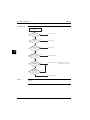
Part 1 – System Outline
Item
Description
1
Space heating / water in
2
Space heating / water out
3
Shut off valve with drain / fill valve (field installation)
4
Expansion vessel
5
Filter
6
Pump
7
Plate heat exchanger
8
Air purge
9
Flow sensor
10
3-way valve
11
Safety valve
12
Boiler
13
Domestic hot water out
14
Gas connection
15
Cold water in
16
R1T - Water OUT PHE
17
R2T - Water OUT
18
R3T - Liquid
19
R4T - Water IN
40
ESIE13-02
Part 2
Specifications
4
2
What is in this part?
This part contains the following chapters:
Chapter
See page
1–Gas Condensing Boiler
42
2–Hydro-box
44
3–Outdoor Unit
46
3
4
5
41
Part 2 – Specifications
Gas Condensing Boiler
1
ESIE13-02
1
Gas Condensing Boiler
1.1
Technical Specifications
2
GAS MODULE
INDOOR UNIT
*EHYKOMB33AA
Function
3
5
Heating only
Thermal load (Hi)
Min. - Max.
kW
7,5-32,7
Heating power CH
Min. - Max.
80/60
kW
7,9-31,9
Efficiency CH
NCV
80/60
%
98
Efficiency CH
NCV
40/30 (30%)
%
107
Heating power DHW
Min. - Max.
kW
7,9-31,9
Efficiency DHW
NCV
%
105
Casing
Colour
Dimensions
Unit
Weight
Unit
RAL9010
Height x width x depth
mm
710x450x240
kg
36
Gas categories
Pressure (mBar)
Brand
Country
Gas category
G20
G25
DAIKIN
UK
II2H3P
20
FR
II2Esi3B/P
20
25
BE
I2E(S)B
20
25
G30
30-37
30
I3P
ROTEX
Part 2 – Specifications
G31
30
SP
II2H3P
20
30-37
IT
II2H3B/P
20
30
DE
II2ELL3P
20
42
25
50
G37
ESIE13-02
Gas Condensing Boiler
Gas type
Natural gas H
Propane P
2H
3P
G20
G31 (propane)
20 mBar
29 mBar
8.4 - 9.6
9.4 - 10.8
8.6 - 9.6
9.8 - 10.8
Gas supply pressure (mBar)
20-30
25-35
ø gas metering ring (mm) (HRE36/30)
6.95
5.25
Minimum rpm (% of max) (parameter d)
25
40
Minimum start rpm (% of max) (parameter F)
70
50
Gas category
CO2% at low setting (L) (
and
2x)
4
2
(with opened casing)
CO2% at high setting (L) (
and
2x)
(with opened casing)
3
4
Sensor
characteristics
NTC 12 kOhm
T [°C]
R [ohm]
T [°C]
R [ohm]
T [°C]
R [ohm]
-15
76020
25
12000
65
2752
-10
58880
30
9805
70
2337
-5
45950
35
8055
75
1994
0
36130
40
6653
80
1707
5
28600
45
5522
85
1467
10
22800
50
4609
90
1266
15
18300
55
3863
95
1096
20
14770
60
3253
100
952
43
Part 2 – Specifications
5
Hydro-box
1
ESIE13-02
2
Hydro-box
2.1
Technical Specifications
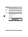
2
EHYHBH05
Casing
3
Dimensions
Colour
Unit
Weight
Net weight
Main components
Pump
Height
mm
900
Width
mm
450
Depth
mm
165
kg
28
Type
DC motor
Inverter controlled
Power input
5
W
Water filter
Brazed plate
Qty
1
Water volume
l
0,9
1,3
Water flow rate
min.
l/min
5,0
11,0
Green felt
l
10
Max. water
pressure
bar
3
Pre-pressure
bar
1
Diameter perforations
mm
1
Part 2 – Specifications
Elastomeric
foam
Body: copper + brass / filter element: stainless
steel
22 mm CU
Piping connections ø
Safety valve
Refrigerant circuit
Green felt
Volume
Material
Heating circuit
45
Type
Insulation material
Expansion vessel
EHYHBX08
White
Nr. of speed
Water side heat
exchanger
EHYHBH08
bar
3
Manometer
Yes
Drain valve / Fill valve
Yes
Shut off valves
Yes
Air purge valve
Yes
Gas side ø
mm
15,9
Liquid side ø
mm
6,35
44
ESIE13-02
Operation range
(heat pump operation)
Hydro-box
Outdoor temperature
Space cooling
°C
Space heating
(heat pump)
°C
Water temperature
Space cooling
°C
Space heating
°C
-
-
10 ~ 43
-25 ~ 25
-
-
4
5 ~ 22
15 ~ 55
2
3
4
5
45
Part 2 – Specifications
Outdoor Unit
1
2
ESIE13-02
3
Outdoor Unit
3.1
Nominal Capacity and Nominal Input
For combination
indoor units and
outdoor units
Outdoor units
3
5
Indoor units
Indoor H/P module
Condition 1
Heating
capacity
Condition 2
EHYRLQ005
EHYRLQ008
EHYRLQ008
EHYHBH05
EHYHBH08
EHYHBX08
Minimum
kW
1,80
1,80
1,80
Nominal
kW
4,40
7,40
7,40
Maximum
kW
5,12
10,02
10,02
Cooling
capacity
Minimum
kW
---
---
2,50
Nominal
kW
---
---
6,86
Heating PI
Nominal
kW
0,87
1,66
1,66
Cooling PI
Nominal
kW
---
---
2,01
COP
Nominal
-
5,04
4,45
4,45
EER
Nominal
-
---
---
3,42
Heating
capacity
Minimum
kW
1,80
1,80
1,80
Nominal
kW
4,03
6,89
6,89
Maximum
kW
4,90
9,53
9,53
Cooling
capacity
Minimum
kW
---
---
2,50
Nominal
kW
---
---
5,36
Heating PI
Nominal
kW
1,13
2,01
2,01
Cooling PI
Nominal
kW
---
---
2,34
COP
Nominal
-
3,58
3,42
3,42
EER
Nominal
-
---
---
2,29
Notes
Part 2 – Specifications
Condition 1
Cooling Ta 35°C - LWE 18°C (DT= 5°C)
Heating Ta DB/WB 7°C/6°C - LWC 35°C (DT= 5°C)
Condition 2
Cooling Ta 35°C - LWE 7°C (DT= 5°C)
Heating Ta DB/WB 7°C/6°C - LWC 45°C (DT= 5°C)
46
ESIE13-02
3.2
Outdoor Unit
Technical Specifications
Casing
4
Colour
Ivory white
Material
Dimensions
Packing
Unit
Weight
Packing
<Polyester painted galvanised steel>
Height
mm
797
Width
mm
990
Depth
mm
390
Height
mm
735
Width
mm
832
Depth
mm
307
Machine weight: ERLQ004* /
ERLQ006* & ERLQ008*
kg
54 / 56
Gross weight: ERLQ004* / ERLQ006*
& ERLQ008*
kg
57 / 59
Material
Heat exchanger
Specifications
Length
kg
3
mm
845
N° of rows
Fin pitch
mm
32
<Hi-Xa(8)>
Type
<WF fin>
Treatment
<Anti-corrosion treatment (PE)>
Type
<Propeller>
Quantity
Air flow rate (nominal at 230V)
1
Heating
m³/min
45
47
47
Cooling
m³/min
52,5
52,5
52,5
Discharge direction
Motor
<Horizontal>
Quantity
Output
Compressor
1
W
53
Quantity
Motor
5
1,8
Tube type
Fan
4
2
N° of stages
Fin
3
EPS, CARTON
Weight
1
Model
2YC36BXD#C
Type
2YC45DXD#C
2YC45DXD#C
<Hermetically sealed swing compressor>
47
2
Part 2 – Specifications
Outdoor Unit
1
2
Operation
range(1)
Sound level
(nominal)
ESIE13-02
Heating (heat
pump)
Min
°CDB
-25
Max
°CDB
25
Cooling
Min
°CWB
10
Max
°CWB
43
Sound power
(4/6/8)
dBA
61 / 61 / 62
Sound pressure
(4/6/8)(2)
dBA
48 / 48 / 49
Sound power
dBA
63 / 63 / 63
Sound pressure
(4/6/8)(2)
dBA
48 / 49 / 50
Heating (heat
pump)
Cooling
3
Refrigerant
Type
<R-410A>
Charge EHYRLQ005 / EHYRLQ008
kg
Control
<Expansion valve (electronic type)>
N° of circuits
Refrigerant oil
1
Type
<FVC50K>
Charged volume
5
Piping connections
Liquid
l
Type
Diameter (OD)
Gas
mm
<6,35>
<Flare connection>
mm
Quantity
<15,9>
2
Type
Piping length
0,75
<Flare connection>
Type
Diameter (OD)
Drain
1.45 / 1.60
Hole
Diameter (OD)
mm
Minimum
m
3
Maximum
m
30
Additional refrigerant charge
kg/m
Height difference
between outdoor
unit and indoor
unit
m
Maximum
1xØ15 + 1xØ20
0,02 IF > 10 m
20
Defrost method
<Reverse cycle>
Defrost control
<Sensor for outdoor heat exchanger temperature>
Capacity control method
<Inverter controlled>
Standard accessories
<Installation manual>
Part 2 – Specifications
Item
Quantity
1
48
ESIE13-02
Outdoor Unit
Notes
(1) See operation range drawing. (*) Range increase by support backup heater. (**) Range increase
by support booster heater or backup heater.
(2) The sound pressure level is measured via a microphone at a certain distance from the unit. It is a
relative value depending on the distance and acoustic environment. Refer to sound spectrum drawing
for more information.
4
2
3
4
5
49
Part 2 – Specifications
Outdoor Unit
ESIE13-02
1
2
3
5
Part 2 – Specifications
50
ESIE13-02
Part 3
Commissioning
4
See ‘Note’ on page 6.
33
4
5
51
Part 3 – Commissioning
ESIE13-02
1
33
5
Part 3 – Commissioning
52
ESIE13-02
Part 4
Troubleshooting
What is in this part?
4
This part contains the following chapters:
Chapter
See page
1–Troubleshooting
54
2–Error Codes: Gas Condensing Boiler
85
3–Error Codes: Hydro-box
94
4–Error Codes: Outdoor Units
103
5–Error Codes: System Malfunctions
139
6–Additional Checks for Troubleshooting
150
3
44
5
53
Part 4 – Troubleshooting
Troubleshooting
1
ESIE13-02
1
Troubleshooting
1.1
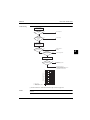
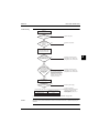
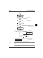
General Troubleshooting Flowchart
Wait until
power failure
is over.
3
YES
YES
Doesn't run at all
Is there a
power
failure?
NO
The power supply switch is NO
OFF or the switch's fuse is
burnt.
YES
Is the remote
controller's operation
lamp blinking?
Runs
The pump comes
on but the
compressor
doesn't run.
YES
Set the remote
controller's temperature
setting to:
(1)When
cooling:Minimum
(2)When
heating:Maximum
Is the remote
controller's operation
NO
lamp blinking?
Machines equipped with
wireless remote
controllers only.
Doesn't run
YES
Cooling starts but
stops right away.
Is the remote
controller's operation
lamp blinking?
(1) The operation circuit fuse is
disconnected or is making poor
contact.
(2) The operation swich is broken or its
contact is defective.
(3) The high pressure switch is broken.
(4) The fan motor's magnetic switch is
broken.
(5) The fan motor's overcurrent relay is
being actuated or is broken.
(6) The compressor's overcurrent relay is
broken.
(7) The compressor's protective
thermostat is broken.
(8) The electrical system insulation is
defective.
(9) The compressor's magnetic switch's
contact is defective.
(10) The compressor is broken.
(11)
(12)
(13)
(14)
Thermostat is broken.
The cool/heat selector is broken.
The operation switch is broken.
The compressor's magnetic swich is
broken.
(15) Over-charged with refrigerant.
(16) Air is mixed inside the refrigerant
circuit.
(17) The pressure switch is broken.
(18) The outdoor unit fan motor's
magnetic switch is broken.
(19) The outdoor unit fan motor's
auxiliary relay is broken.
Ask for the character
code of the malfunction
code.
5
NO
Troubleshooting by
remote controller
malfunction code.
Normal
4
Refer to "Remote controller display
malfunction code and contents".
Troubleshooting by
remote controller
malfunction code.
Turn the power supply
switch ON or replace
the fuse.
NO
Cooling
(20) The outdoor unit's heat exchanger
is dirty.
(21) There is something blocking the
outdoor unit's air flow.
(22) Malfunction of the outdoor unit's
fan.
Heating
(23) flow error
Nomal
The unit won't run
again for a while
after stopping.
Try turning the
Operation switch OFF
and On.
Did you allow 3 minutes to
elapse after turning ON?
YES
NO
Runs
(24)
(25)
(26)
(26)-1
Operation is
normal.
Is there something causing the
indoor load to be large, such as
an open window or door?
The unit runs but
doesn't cool the
room.
YES
Temperature
differential is 8~18˚C
Measure the suction
/disharge temperature.
NO
(26)-2
(26)-3
(26)-4
(27)
(27)-1
(27)-2
(27)-3
(Temperature differential
=suction temperature - discharge temperature)
(27)-4
(27)-5
Overcurrent relay (for compressor)
Compressor's protective themostat
The causes for the overcurrent
relay (for compressor) being
actuated are:
Power supply voltage is lower than
prescribed.
High pressure is too high.
The power supply cord is too small.
The compressor is broken.
The causes for the compressor's
protective thermostat
Internal leak of the-4way valve
(No substantial difference between
suction and discharge temperature.
Unsatisfactory compression from
the compressor
Different kind of refrigerant is
charged.
Malfunction of the expansion valve
Unsatisfactory refrigerant circulation
Operation is
normal.
Is there something causing the
indoor heat load to be large, such
as an open window or door?
The units runs but
doesn't heat the
room.
YES
Temperature
differential is 14~30˚C
Measure the suction
/disharge temperature.
(Temperature differential
=discharge temperature - suction temperature)
Part 4 – Troubleshooting
54
NO
OK.We'll be right over.
(Service work required)
ESIE13-02
1.2
Troubleshooting
Overview of General Problems
General guidelines
4
Before starting the troubleshooting procedure, carry out a thorough visual inspection of the unit and
look for obvious defects such as loose connections or defective wiring.
Before contacting your local Daikin dealer, read this chapter carefully, it will save you time and money.
Warning! When carrying out an inspection on the switch box of the unit, always make sure that the
main switch of the unit is switched off.
When a safety device was activated, stop the unit and find out why the safety device was activated
before resetting it. Under no circumstances safety devices may be bridged or changed to a value other
than the factory setting. If the cause of the problem cannot be found, call your local Daikin dealer.
If the pressure relief valve is not working correctly and is to be replaced, always reconnect the flexible
hose attached to the pressure relief valve, to avoid water dripping out of the unit!
3
General symptoms
Error codes
Equipment Condition
Remedy
1.2.1
Equipment does not Operate
See page 56
1.2.2
Indoor Pump Operates, but Compressor does not
See page 57
1.2.3
Cooling/Heating Operation Starts but Stops Immediately
See page 59
1.2.4
After Unit Shuts Down, It cannot be Restarted for a While
See page 61
1.2.5
Equipment Produces Loud Noise or Shakes
See page 63
1.2.6
User Interface Displays “Busy”
See page 65
1.2.7
The Unit is Turned on (d LED is lit) but the Unit is not Heating
or Cooling as Expected
See page 66
1.2.8
The Unit is Turned on but the Compressor is not Starting
(Space Heating or Domestic Heating)
See page 67
1.2.9
Pump is Making Noise (Cavitation)
See page 68
1.2.10
The Water Pressure Relief Valve Opens
See page 69
1.2.11
The Water Pressure Relief Valve Leaks
See page 70
1.2.12
The User Interface Does Not Display Certain Screens (RT,
LWT, Tank, Ext RT)
See page 71
1.2.13
Domestic Hot Water Capacity Shortage at Low Outdoor Temperatures
See page 72
1.2.14
Space Heating Capacity Shortage at Low Outdoor Temperatures
See page 73
1.2.15
Room Temperature Set Point Isn’t Reached or Increases Too
Slow
See page 74
When a safety device is activated, the user interface will display the t-icon on the home screen. When
pushing the t-button, the error code and a brief description of the error will be shown.
A short list of all errors and corrective actions can be found in the installer reference guide. More
detailed information on how to solve these errors can be found in the next pages.
55
Part 4 – Troubleshooting
44
5
Troubleshooting
1
1.2.1
ESIE13-02
Equipment does not Operate
Applicable model
ERHQ011~016*
ERLQ004~016*
Error detection
method
Error generating
condition
3
Supposed causes
4
5
Fuse blown or disorder of contact in operation circuit
Faulty operation switch or contact point
Faulty high pressure switch
Faulty magnetic switch for fan motor
Activation or fault of overcurrent relay for fan motor
Faulty overcurrent relay for compressor
Faulty compressor protection thermostat
Insufficient insulation in electric system
Faulty contact point of magnetic switch for compressor
Malfunction of compressor
Defective remote controller
Troubleshooting
Is power switch
OFF or fuse for power switch
blown?
YES
NO
Is there power
failure?
YES
Turn on power switch or replace
fuse.
If high-harmonics circuit breaker is
not used on inverter compressor,
have the circuit breaker replaced.
Wait until power returns.
NO
Is operation
switch pressed
repeatedly?
YES
Is
operation lamp on
LCD remote controller
flashing?
NO
Is
thermostat changed and
reset again?
YES
NO
NO
NO
Possibly faulty electric
component
Caution
Part 4 – Troubleshooting
Normal.
Equipment starts operation 3
minutes later (3-min standby).
YES
Diagnose based on error code on
remote controller.
Normal.
Equipment starts operation 3
minutes later (3-min standby).
Check electric system.
Be sure to turn off power switch before connect or disconnect connector, or parts damage may be
occurred.
56
ESIE13-02
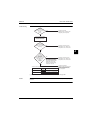
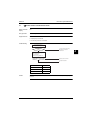
1.2.2
Troubleshooting
Indoor Pump Operates, but Compressor does not
Applicable model
4
ERHQ011~016*
ERLQ004~016*
Error detection
method
Error generating
condition
Supposed causes
3
Faulty thermistor
Faulty indoor/outdoor unit PC board
Faulty magnetic switch
Faulty power transistor
Faulty compressor
Continuous pump operation enabled by setting
44
5
57
Part 4 – Troubleshooting
Troubleshooting
1
ESIE13-02
Troubleshooting
· Hydro-box pump runs at set flow rate.
Is setting A.2.1.9
pump operation mode set to
(0) = continuous pump
operation?
YES
Normal operation.
NO
Is the power
switch OFF or the fuse for
power switch
blown?
3
YES
Turn on the power
switch or replace fuse.
NO
Is the heating
switch turned on at outdoor
temperature
>35°C
4
YES
NO
1
Is rated
voltage applied at the
compressor
terminals?
YES
NO
2
Is rated
voltage output from the
magnetic switch or power
transistor?
5
Normal.
(Thermostat OFF by
outdoor temperature)
Replace the compressor.
YES
NO
3
Is rated
voltage output from the
PC board?
Replace the magnetic
switch or power transistor.
YES
Replace the PC board.
NO
Check the thermistor.
Sensor
Hydro-box
PC board
Input
to PC
board
Caution
Part 4 – Troubleshooting
Output
from
PC
board
Outdoor unit
PC board
Magnetic
switch
Relay
Input
to PC
board
3
Output from
relay or
microcomputer
COMP
2
Output from
magnetic
switch or SW
circuit of
power
transistor
1
Output from
magnetic
switch or
U,V,W of
power
transistor
Be sure to turn off power switch before connect or disconnect connector, or parts damage may be
occurred.
58
ESIE13-02
1.2.3
Troubleshooting
Cooling/Heating Operation Starts but Stops Immediately
Applicable model
4
ERHQ011~016*
ERLQ004~016*
Error detection
method
Error generating
condition
Supposed causes
3
Excess charge of refrigerant
Air intrudes into refrigerant system
Faulty pressure switch
Faulty magnetic switch for outdoor unit fan motor
Faulty aux. relay for outdoor unit fan motor
Soiled heat exchanger of outdoor unit
There is an interfering item in air flow of outdoor unit
Malfunction of outdoor unit fan
Soiled air filter of hydro-box
Malfunction of hydro-box pump (flow error)
59
44
5
Part 4 – Troubleshooting
Troubleshooting
1
ESIE13-02
Troubleshooting
Is the
type of remote controller
wired or wireless?
Hydro-box
[ Heating:
Cooling: Outdoor unit ]
Is the remote
controller displaying the
t-symbol?
NO
Does the pump/fan rotate?
NO
Is there
any item disturbing
air/waterflow?
NO
3
Is the heat
exchanger soiled?
Diagnose based on the
error code on remote
controller
NO
Malfunction of fan motor
Check the magnetic
switch and aux. switch for
pump/fan motor
YES
Is the filter soiled?
YES
YES
Hydro-box flow error
YES
Hydro-box flow error
YES
Cleaning
Remove the disturbing
item.
Cleaning of the heat
exchanger
NO
Possible causes as follows:
* Refrigerant overcharge
* Mixing of air in refrigerant
system
* Faulty pressure switch
4
5
Caution
Part 4 – Troubleshooting
After vacuum drying,
charge correct amount of
refrigerant
Check the pressure
switch.
Be sure to turn off power switch before connect or disconnect connector, or parts damage may be
occurred.
60
ESIE13-02
1.2.4
Troubleshooting
After Unit Shuts Down, It cannot be Restarted for a While
Applicable model
4
ERHQ011~016*
ERLQ004~016*
Error detection
method
Error generating
condition
Supposed causes
Overcurrent relay (for compressor)
Compressor protection thermostat
Overcurrent relay may act due to the following reasons:
Lower voltage of power supply
Excess level of high pressure
Insufficient size of power cable
Malfunction of compressor
3
44
Compressor protection thermostat may act due to the following reasons:
Internal leakage of four-way valve (There is no difference between suction and discharge
temperature)
Insufficient compression of compressor
Incorrect refrigerant
Faulty expansion valve
Insufficient circulation of refrigerant
61
5
Part 4 – Troubleshooting
Troubleshooting
1
ESIE13-02
Troubleshooting
Turn the operation switch
ON and OFF, then wait at
ON side.
Does the unit
start operation after 3
minutes?
YES
Power supply
voltage is within ±10 % of
specified voltage.
NO
Is the
discharge side of
compressor hot after
unit stop?
3
Normal. Unit is in 3-min
standby mode
[Electric system]
NO Not so hot
Check on the cause why
overcurrent relay (for
compressor) or compressor
protection thermostat acted.
YES
Is the
size of power cable
through total length
correct?
YES
NO
[Refrigerant circuit]
Contact power company.
Check compressor.
NO
Replace power cable.
YES
After vacuum drying, charge
correct amount of refrigerant. Then,
start operation again.
4
Is there any
temperature difference
between inlet and outlet of
expansion
valve?
YES
Is
there any
temperature difference
between suction side and
discharge side of fourway valve?
5
NO
NO
Expansion valve
malfunction
Four-way valve
malfunction
YES
Malfunction of compressor
Caution
Part 4 – Troubleshooting
Check compressor.
Be sure to turn off power switch before connect or disconnect connector, or parts damage may be
occurred.
62
ESIE13-02
1.2.5
Troubleshooting
Equipment Produces Loud Noise or Shakes
Applicable model
4
ERHQ011~016*
ERLQ004~016*
Error detection
method
Error generating
condition
Supposed causes
3
Faulty installation
Excess charge of refrigerant
Air intrudes into refrigerant system
Flushing noise due to refrigerant shortage. (Sound of shoo...)
44
5
63
Part 4 – Troubleshooting
Troubleshooting
1
ESIE13-02
Troubleshooting
[Installation work side]
Does the
YES
noise generate with
vibration of whole ceilings
and walls?
Correction of installation
Reinforcement for ceilings or
walls
NO
Does the
YES
noise generate with
vibration of unit mounting
section?
Insert shock absorber in
mounting section, or strengthen
the mounting section.
Continuous
slight noise of "shoo..." during
cooling or defrosting
NO
3
Is the piping
secured?
NO
Sound of
"shoo..." generates
just after operation start or
stop, or defrosting start
or stop.
YES
4
YES
Normal. The sound is flushing
noise of gas (refrigerant) inside
air conditioning unit
Insert cushion materials to the
pipe support such as saddle.
NO
[Power supply side]
Does
the fan contact with
other parts?
YES
YES
NO
Normal. The noise is a sound
generated at the time of gas
(refrigerant) flow change or stop
Disassemble and remove parts
contact.
NO
Does
the pipe contact with
casing?
5
YES
Correct piping manually or
attach a dead weight to pipe
NO
Creak during
heating and after operation
stop
Is
the noise flushing
YES
sound from pressure reducing
valve or capillary
tube?
YES
NO
Is
this an impact
noise at the start/end of
defrosting?
NO
Normal. Creak generates by
shrinkage of resin parts due to
temperature change.
Normal.
YES
It is normal.
NO
∗ Excess charge of refrigerant
∗ Air intrudes into refrigerant
YES
system
After vacuum drying, charge
∗ Flushing noise due to
correct amount of refrigerant.
refrigerant shortage.
(Sound of shoo...)
Caution
Part 4 – Troubleshooting
Be sure to turn off power switch before connect or disconnect connector, or parts damage may be
occurred.
64
ESIE13-02
1.2.6
Troubleshooting
User Interface Displays “Busy”
Applicable model
4
EHB/V*CA
Error detection
method
Error generating
condition
Supposed causes
3
Troubleshooting
Trouble generates
just after power supply ON
YES
The unit is checking to confirm that
remote controller is normal.
Indication appears for short time.
NO
44
Check the unit based on
hydro-box LED and outdoor unit
LED. (Troubleshooting)
Caution
Be sure to turn off power switch before connect or disconnect connector, or parts damage may have
occurred.
65
Part 4 – Troubleshooting
5
Troubleshooting
1
1.2.7
ESIE13-02
The Unit is Turned on (d LED is lit) but the Unit is not Heating or Cooling as
Expected
Applicable models
EHB*CA, EHV*CA, ERHQ011~016*, ERLQ004~016*
Error detection
method
Error generating
condition
3
Supposed causes corrective action
Possible causes
Corrective action
The temperature setting is not correct.
Check the controller set point.
The water flow is too low.
Check that all shut off valves of the water
circuit are completely open.
Check if the water filter needs cleaning.
Make sure there is no air in the system (purge
air).
Check on the manometer that there is
sufficient water pressure. The water pressure
must be >1.5 bar.
Check that the pump speed setting is on the
highest speed.
Make sure that the expansion vessel is not
broken.
Check that the resistance in the water circuit
is not too high for the pump.
4
5
The water volume in the installation is too low.
Part 4 – Troubleshooting
66
Make sure that the water volume in the installation is above the minimum required value (refer
to the “Specifications” in databook).
ESIE13-02
1.2.8
Troubleshooting
The Unit is Turned on but the Compressor is not Starting (Space Heating or
Domestic Heating)
Applicable models
4
EHB*CA, EHV*CA, ERHQ011~016*, ERLQ004~016*
Error detection
method
Error generating
condition
Supposed causes corrective action
3
Possible causes
Corrective action
The unit must start up out of its operation range
(the water temperature is too low).
In case of low water temperature, the system utilizes the backup heater to reach the minimum
water temperature first (18°C).
67
Check that the backup heater power supply is
correct.
Check that faston terminals are connected
correctly (instruction can be found in the
Installer Reference Guide in Appendix on
page 35).
Check that the backup heater thermal fuse is
closed.
Check that the thermal protector backup
heater is not activated.
Check that the backup heater contactors are
not broken.
Part 4 – Troubleshooting
44
5
Troubleshooting
1
1.2.9
ESIE13-02
Pump is Making Noise (Cavitation)
Applicable models
EHB*CA, EHV*CA
Error detection
method
Error generating
condition
3
Supposed causes corrective action
Possible causes
Corrective action
There is air in the system.
Purge air.
Water pressure at pump inlet is too low.
Check on the manometer on the unit that
there is sufficient water pressure. The water
pressure must be >1.5 bar.
Check that the manometer is not broken.
Check that the expansion vessel is not
broken.
Check that the setting of the pre-pressure of
the expansion vessel is correct (refer to the
installer reference guide attached in
Appendix to this Service Manual on page 23).
4
5
Part 4 – Troubleshooting
68
ESIE13-02
Troubleshooting
1.2.10 The Water Pressure Relief Valve Opens
Applicable models
4
EHB*CA, EHV*CA
Error detection
method
Error generating
condition
Supposed causes corrective action
3
Possible causes
Corrective action
The expansion vessel is broken.
Replace the expansion vessel.
The water volume in the installation is too high.
Make sure that the water volume in the installation is under the maximum allowed value (refer
to the “Specifications” in databook).
44
5
69
Part 4 – Troubleshooting
Troubleshooting
1
ESIE13-02
1.2.11 The Water Pressure Relief Valve Leaks
Applicable models
EHB*CA, EHV*CA
Error detection
method
Error generating
condition
3
Supposed causes corrective action
Possible causes
Corrective action
Dirt is blocking the water pressure relief valve
outlet.
Check for correct operation of the pressure relief
valve by turning the red knob on the valve counter clockwise:
4
5
Part 4 – Troubleshooting
70
If you do not hear a clacking sound, contact
your local Daikin dealer.
In case the water keeps running out of the
unit, close both the water inlet and outlet
shut-off valves first and then contact your
local Daikin dealer.
ESIE13-02
Troubleshooting
1.2.12 The User Interface Does Not Display Certain Screens (RT, LWT, Tank, Ext RT)
Applicable models
4
EHB*CA, EHV*CA
Error detection
method
Error generating
condition
Supposed causes corrective action
3
Possible causes
Corrective action
The tank-screen is not visible.
Check if there is a tank connected? Then setting
A.2.2.1. should be set to yes.
The RT-screen is not visible.
Check setting A.2.1. to see if unit control method
is set to Room Thermostat control.
The ext RT-screen is not visible.
Check setting A.2.1. to see if unit control method
is set to ext Room Thermostat control.
The LWT-screen is not visible.
1. Check setting A.2.1. to see if unit control
method is set to LWT.
44
2. Check 7.4.1 (user settings - available home
page if LWT screen is enabled).
5
71
Part 4 – Troubleshooting
Troubleshooting
1
ESIE13-02
1.2.13 Domestic Hot Water Capacity Shortage at Low Outdoor Temperatures
Applicable models
EHB*CA, EHV*CA, ERHQ011~016B/CA, ERLQ004~016CA
Error detection
method
Error generating
condition
3
Supposed causes corrective action
4
Possible causes
Corrective action
The settings related to domestic hot water operation at low Ta - space heating priority [5-02]
and space heating priority temperature [5-03] are not set or not optimized according to the site
application(1).
Optimize the settings related to domestic hot
water operation at low Ta - space heating priority
[5-02] and space heating priority temperature
[5-03] - according to the site application:
[5-02] = “1”
[5-03] = “[5-01](2) + 3~5°C”
(1)
In case the Daikin Altherma LT has no spare capacity compare to the space heating load at low Ta
(see equilibrium temperature [5-01]), the priority shall be given towards space heating (see
anti-recycling timer [8-02] and maximum running timer for domestic hot water [8-01]) and domestic hot
water shall be covered/supported by the electrical heater (To guarantee sufficient domestic hot water
and reasonable domestic hot water heat-up times).
5
(2)
The applicable Ta can be determined via the Daikin Altherma simulation software
(extranet/software/downloads/altherma/altherma_new_LT).
Part 4 – Troubleshooting
72
ESIE13-02
Troubleshooting
1.2.14 Space Heating Capacity Shortage at Low Outdoor Temperatures
Applicable models
4
EHB*CA, EHV*CA
Error detection
method
Error generating
condition
Supposed causes corrective action
A. General: independent from DHW - setpoint mode
3
Possible causes
Corrective action
The settings related to space heating operation
at low Ta - equilibrium temperature status
(backup heater allowance) [5-00] and equilibrium temperature [5-01] - are not set or not optimized according to the site application(1).
Optimize the settings related to space heating
operation at low Ta - equilibrium temperature
status (backup heater allowance) [5-00] and
equilibrium temperature [5-01] - according to the
site application:
[5-00] = “1”
[5-01] = the applicable Ta where the heating
load and Altherma Hybrid available heating
capacity are in balance*.
Other related settings to optimize:
73
[5-02] = “1”
[5-03] =
“[5-01](2)
+ 3~5°C”
Part 4 – Troubleshooting
44
5
Troubleshooting
1
ESIE13-02
1.2.15 Room Temperature Set Point Isn’t Reached or Increases Too Slow
Applicable models
EHB*CA, EHV*CA
Error detection
method
Error generating
condition
3
Supposed causes corrective action
4
Possible causes
Corrective action
See possible causes of item “2 Possible space
heating capacity shortage at low Ta”.
See corrective actions of item “2 Possible space
heating capacity shortage at low Ta”.
The leaving water temperature set point
(weather dependent or fixed) is too low in relation with the target room temperature set point.
Select the desired leaving water temperature(1)
in balance with the desired room temperature(2)
and/or the capacity. Secondly the desired leaving water temperature shall be in relation to the
temperature difference between inlet and outlet
water temperature of the heat emitters (according to the design and selection of the heat emitters).
(1)
5
The desired leaving water temperature is the result of several settings (preset values, shift values,
weather dependent curves, modulation). As a result, too high or too low leaving water temperature
could occur which lead to overtemperatures or capacity shortage. By limiting the leaving water
temperature range to adequate values (depending on the heat emitter), such situations can be
avoided.
(2)
The feasible room temperature dependents on the average heat emitter surface temperature. The
average heat emitter surface temperature is determined by the temperature difference between the
inlet and outlet water temperature of the heat emitter.
Part 4 – Troubleshooting
74
ESIE13-02
1.3
Troubleshooting
Fault-diagnosis by Remote Controller
Explanation
4
If operation stops due to malfunction (error or warning), the user interface home screen will indicate
the t-symbol. The malfunction code plus a short description of the error is displayed when pushing
the t-button on the user interface. In case of a warning, the unit will continue operation. In case of an
error, the unit will preventively shut down.
3
Attention!
Some errors can only be reset when in installer level! The malfunction code enables you to tell what
kind of malfunction caused operation to stop. See next pages for malfunction code and malfunction
contents.
44
5
75
Part 4 – Troubleshooting
Troubleshooting
1
1.4
ESIE13-02
Fault-diagnosis Manual Reset in the Memory
Explanation
In order to reset the malfunction code in the remote controller memory, follow actions has to be
performed.
Remark
For some malfunction codes it’s required to manually reset the malfunction code in the memory before
the unit can be restarted.
3
4
5
Part 4 – Troubleshooting
76
ESIE13-02
1.4.1
Troubleshooting
Remote Controller Display Malfunction Code and Contents
Malfunction code
Outdoor Unit
Hydro-box
80
Contents/Processing
4
Remarks
Inlet water temperature thermistor abnormality
81
Outlet water temperature thermistor abnormality
89
Water heat exchanger freeze-up abnormality
7H
Water flow abnormality
8F
Outlet water temperature too high
8H
Outlet water temperature too high
AA
Booster or back-up heater thermal protector is open
AC
Booster heater thermal protector is open
AH
Warning tank disinfection function not completed correctly
A1
Hydro-box PCB abnormality
CJ
Room temperature thermistor error
C0
Flow switch abnormality
C4
Heat exchanger thermistor abnormality
EC
Domestic hot water temperature too high
HC
Domestic hot water temperature thermistor abnormality
H1
External temperature sensor error
E1
Outdoor unit PC board malfunction
3
44
E3
High pressure malfunction (outdoor unit)
E4
Abnormality of low pressure (outdoor)
Failure of low pressure sensor system. Check if
the stop valve is open.
E5
Compressor motor lock malfunction
Compressor motor lock, incorrect wiring.
E7
Outdoor fan motor lock or outdoor fan instantaneous
overcurrent malfunction
E9
Malfunction of electronic expansion valve (outdoor unit)
F3
Discharge pipe temperature malfunction (outdoor unit)
H3
Failure of high pressure switch (outdoor unit)
H9
Malfunction of outdoor air temperature sensor system
(outdoor unit)
J1
Malfunction of pressure sensor
J3
Malfunction of discharge pipe temperature sensor system
(outdoor unit)
J3
Malfunction of discharge pipe temperature sensor system
(outdoor unit)
J5
Suction pipe thermistor malfunction
J6
Malfunction of heat exchanger temperature sensor system
(outdoor unit)
J7
Malfunction of subcooling heat exchanger thermistor
(outdoor unit)
J8
Malfunction of liquid pipe thermistor (outdoor unit)
L1
Outdoor PC board malfunction
5
L4
Radiation fin temperature rise
Malfunction of inverter cooling
L5
Instantaneous over current
Possibility of compressor motor grounding or
shortage of motor winding
L8
Electronic thermal
Possibility of compressor overload, open circuit
in compressor motor
L9
Stall prevention
Possibility of compressor seizing
LC
Malfunction of transmission system (between control PCB
and inverter PCB)
P1
Open phase or voltage unbalance
P4
Abnormal radiation fin temperature sensor (outdoor unit)
PJ
Failure of capacity setting (outdoor unit)
77
Either capacity data is set incorrectly, or
capacity has not been set for the data IC
Part 4 – Troubleshooting
Troubleshooting
ESIE13-02
Malfunction code
1
Contents/Processing
U0
Remarks
Lack of gas malfunction
U0
Abnormal suction pipe temperature
U0
U2
Abnormal power supply voltage
Including malfunction of K10R, K11R
U3
Underfloor heating screed dry-out error
Can only be reset when in installer level
Failure of transmission (between hydro-box and outdoor
unit)
Transmission between hydro-box and outdoor
Failure of transmission (between hydro-box and outdoor
unit)
Transmission between hydro-box and outdoor
unit is not being carried out correctly.
System
malfunctions
U4/UF
UF
or
or
3
unit is not being carried out correctly. (1)
Gas shortage
There is very little or no refrigerant flow within
the hydro-box.
U5
Failure of transmission (between hydro-box and remote
controller)
Transmission between hydro-box and remote
controller is not being carried out correctly.
UA
Incorrect hydro-box connected to the system
or unit type connection not confirmed
In case of spare part PCB.
Legend
4
Colour
Meaning
Error code displays automatically and system stops.
Inspect and repair it.
In case of shaded error codes, ‘inspection’ is not displayed. The system operates
but be sure to inspect and repair it.
5
Error code displayed on user interface.
The system operates, but be sure to inspect and repair it.
Note
Part 4 – Troubleshooting
(1)
There is a possibility of open phase power supply, check power supply also.
78
ESIE13-02
1.5
Overview
Troubleshooting
Troubleshooting by LED on the Hydro-box PCB
4
Troubleshooting can be carried out by HAP LED (green). (Blinks when normal)
w: LED on / x : LED off / c : LED blinks
Microcomputer Normal
Monitor
Contents/Processing
HAP (LED-A)
w
x
Notes
Failure of hydro-box PC board assembly (Note 5)
Malfunction of power supply or failure of PC board assembly or broken
transmission wire between indoor and outdoor unit. (Note 5)
1
Operation halts due to malfunction depending on the model or condition.
2
Troubleshoot by turning off the power supply for a minimum of 5 seconds, turning it back on, and
then rechecking the LED display.
3
44
5
79
Part 4 – Troubleshooting
Troubleshooting
1
1.6
ESIE13-02
Overview of Error Codes
Abbreviations
DHW= domestic hot water
SPH= space heating
BUH= back-up heater
BSH= booster heater
PHE= plate heat exchanger
3
1.6.1
Hydro-box Malfunction
Overview
Remote
Controller
Display
4
80
81
89
7H
AH
A1
CJ
C0
C4
EC
H1
HC
5
Part 4 – Troubleshooting
Contents of Malfunction
Return water temperature thermistor abnormality
Leaving water temperature thermistor abnormality
PHE freeze-up protection control
Water flow abnormality
Tank disinfection function not completed correctly
Zero cross detection problem. Power reset required
Room temperature sensor problem
Flow sensor abnormality
Heat exchanger thermistor abnormality
Abnormal increase tank temperature
External temperature sensor problem
Tank temperature thermistor problem
80
Details of
Malfunction
(Reference
Page)
96
96
95
97
102
94
96
100
96
101
96
96
ESIE13-02
1.6.2
Troubleshooting
Outdoor Unit Malfunction
4
Overview
Remote
Controller
Display
Contents of Malfunction
E1
E3
E4
E5
E7
E9
F3
H3
H9
J1
J3
J5
J6
J7
Outdoor unit PC board malfunction
Abnormality of high pressure (HPS)
Abnormality of low pressure (outdoor)
Compressor motor lock malfunction
Malfunction of outdoor unit fan motor
Malfunction of Electronic expansion valve
Discharge pipe temperature malfunction
Faulty high pressure switch (HPS)
Malfunction of outdoor air temperature sensor system
Malfunction of pressure sensor
Malfunction of discharge pipe temperature sensor system
Suction pipe thermistor malfunction
Malfunction of heat exchanger temperature sensor system
Malfunction of subcooling heat exchanger temperature sensor
system (outdoor unit)
Malfunction of liquid pipe thermistor (outdoor unit)
Outdoor PC board malfunction
High temperature of radiation fin
Overcurrent of DC output (instantaneous)
Electronic thermal switch (time lag)
Stall prevention (time lag)
Malfunction of transmission system (between control PCB and
inverter PCB)
Open phase or voltage unbalance
Malfunction of radiator fin temperature thermistor
Error in capacity setting
J8
L1
L4
L5
L8
L9
LC
P1
P4
PJ
81
Details of
Malfunction
(Reference
Page)
103
104
106
109
111
114
117
119
121
122
121
121
121
121
121
124
126
128
130
132
134
136
137
138
Part 4 – Troubleshooting
3
44
5
Troubleshooting
1
1.6.3
ESIE13-02
System Malfunction
Overview
Remote
Controller
Display
U0
U2
U3
U4
or UF
UF
3
4
U5
UA
Note
(1)
Contents of Malfunction
Gas shortage
Abnormal power supply voltage
Underfloor heating screed dry-out error
Transmission error (between hydro-box and outdoor unit) (1)
139
141
143
144
Malfunction of transmission (between hydro-box and outdoor
unit) or gas shortage
Transmission error (between hydro-box and user interface)
Incorrect hydro-box connected to this system or unit type
connection not confirmed
146
Possibility of open phase power supply.
5
Part 4 – Troubleshooting
Details of
Malfunction
(Reference
Page)
82
148
149
ESIE13-02
1.7
Troubleshooting
Overview of the Outdoor Safety Devices
4
High pressure switch
Fuse
Open
Close
ERHQ011~016BA
4.0 MPa +0/-0.15
3.0 +/-0.15
6.3A/250V
ERLQ-CA
4.17 MPa +0/-0.15
3.2 +/-0.15
6.3A/250V
3
44
5
83
Part 4 – Troubleshooting
Troubleshooting
1
1.8
ESIE13-02
Overview of the Hydro-box Safety Devices
Hydro-box
EVLQXXCAV3
Protector
Cut-out condition
Reference
Q1L (Clixon)
85 +0/-6°C
4P312728
F1T (Thermal fuse)
134°C +3/-2°C
AD120151
B1L004
Min 5l/min in hp operation. If
3V BUH: min 12l/min
AD120120
B1L008~016
Min 11l/min in hp operation.
If 3V BUH: min 12l/min
If 9W BUH: min 15l/min
AD120120
3
Tank
4
Protector (Clixon)
Cut-out condition
Reference
EKSWW
Q2L
85°C ± 3°C
4SW03476-1
EKSWWU
Q2L
85°C ± 3°C
4SW03476-1
Q3L
85°C ± 3°C
Q2L
85°C ± 3°C
Q3L
85°C ± 3°C
Q2L
91°C ± 3°C
4SW05637-2
Q3L
85°C ± 3°C
4SW05637-1
Q2L
85°C ± 3°C
4SW05637-3
Q3L
85°C ± 3°C
EKHWE - V3
Q2L
89°C +0 / -8°C
4SW05724-1
EKWE - Z2
Q2L
89°C +0 / -8°C
4SW05724-1
Q3L
89°C +0 / -8°C
EKHWS - V3
5
EKHWS - Z2
EKHWSU - V3
EHV - CA
Part 4 – Troubleshooting
4SW05637-1
No clixon on tank since no BSH in tank. Only relevant clixon is clixon
from BUH.
84
ESIE13-02
Error Codes: Gas Condensing Boiler
2
Error Codes: Gas Condensing Boiler
2.1
General Guidelines
4
Before starting the troubleshooting procedure, carry out a thorough visual inspection of the unit and
look for obvious defects such as loose connections or defective wiring.
Warning
When carrying out an inspection on the switch box of the unit, always make sure that the unit is
disconnected from the mains. Turn off the respective circuit breaker.
When a safety device was activated, stop the unit and find out why the safety device was activated
before resetting it. NEVER bridge safety devices or change their values to a value other than the
factory default setting. If you are unable to find the cause of the problem, call your dealer.
Danger
RISK OF ELECTROCUTION.
Warning
Prevent hazard due to the inadvertent resetting of the thermal cut-out: this appliance must NOT be
supplied through an external switching device, such as a timer, or connected to a circuit that is
regularly turned ON and OFF by the utility.
Danger
RISK OF BURNING.
3
44
5
85
Part 4 – Troubleshooting
Error Codes: Gas Condensing Boiler
1
2.2
ESIE13-02
Solving Problems Based on Symptoms
Not available at this moment.
3
4
5
Part 4 – Troubleshooting
86
ESIE13-02
2.3
Error Codes: Gas Condensing Boiler
Solving Problems Based on Error Codes
4
When a problem happens, an error code appears on the user interface. It is important to understand
the problem and to take countermeasure before resetting the error code. This should be done by a
licensed installer or by your local dealer.
This chapter gives you an overview of all error codes and the content of the error code as it appears
on the user interface.
For a more detailed troubleshooting guideline for each error, please see the service manual.
2.3.1
3
Error codes: Overview
Error codes of the
gas boiler
The controller on the gas boiler detects faults and indicates them on the display by error codes.
44
If the LED is flashing, the controller has detected a problem. Once the problem is rectified, the
controller can be restarted by pressing the f button.
Following table shows a list of error codes and the possible solutions.
Error
code
10, 11,
12, 13,
14
Cause
Possible solution
Sensor fault S1.
Check wiring.
Replace S1.
Flow sensor cannot close.
Check flow switch.
20, 21,
22, 23,
24
Sensor fault S2.
Check wiring.
Replace S2.
0
Sensor fault after self-check.
Replace S1 and/or S2.
1
Temperature too high.
Air in installation.
Pump is NOT running.
Insufficient flow in installation.
Radiators are closed.
Pump setting is too low.
Flow switch is sticking.
Check cable set.
Replace S1 and S2.
Gas tap is closed.
No or incorrect ignition gap.
Gas supply pressure is too low or fails.
Gas valve or ignition unit is NOT powered.
2
4
S1 and S2 interchanged.
No flame signal.
87
Part 4 – Troubleshooting
5
Error Codes: Gas Condensing Boiler
1
Error
code
Cause
Possible solution
5
Poor flame signal.
Condensate drain blocked.
Check adjustment of gas valve.
6
Flame detection fault.
Replace ignition cable and spark plug cap.
Replace ignition unit.
Replace boiler controller.
Fan catching on casing.
Wiring between fan and casing.
Check wiring for poor wire contact.
Replace fan.
8
3
ESIE13-02
29, 30
Incorrect fan speed.
Gas valve relay fault.
Replace boiler controller.
4
5
Part 4 – Troubleshooting
88
ESIE13-02
Error Codes: Gas Condensing Boiler
2.4
Symptoms
2.4.1
Burner does not ignite
4
Possible causes:
Solution:
Gas tap is closed.
Yes
Open gas tap.
No
Air in the gas pipe.
Yes
Remove air from gas pipe.
3
No
Gas supply pressure too low.
Yes
Contact the gas company.
No
No ignition.
Yes
Replace ignition pin.
44
No
No spark. Ignition unit on gas block
faulty.
Yes
Check the cabling. Check the spark
plug cap. Replace the ignition unit.
No
Gas/air adjustment not correctly set.
Yes
Check adjustment. See gas/air adjustment.
Yes
Check the wiring. Check the fuse, if
necessary, replace the fan.
No
Fan faulty.
No
Fan dirty.
Yes
Clean the fan.
No
Gas block faulty.
Yes
89
Replace the gas block. Re-adjust the
gas block, see gas/air adjustment.
Part 4 – Troubleshooting
5
Error Codes: Gas Condensing Boiler
1
2.4.2
ESIE13-02
Burner ignites noisily
Possible causes:
Solution:
Gas supply pressure too high.
Yes
The house pressure switch may be
faulty. Contact the gas company.
Yes
Replace the ignition pin. Check the
ignition pin gap.
Yes
Check the setting. See gas/air adjustment.
Yes
Check the ignition gap. Replace the
ignition pin. Replace the ignition unit
(transformer) on the gas block.
No
Incorrect ignition gap.
No
3
Gas/air adjustment not correctly set.
No
Weak spark.
28.3~30.2 mm
4
5
Spark gap (±4.5 mm)
2.4.3
Burner resonating
Possible causes:
Solution:
Gas supply pressure too low.
Yes
The house pressure switch may be
faulty. Contact the gas company.
No
Recirculation of combustion gasses.
Yes
Check the gas flue and the air supply.
No
Gas/air adjustment not correctly set.
Part 4 – Troubleshooting
90
Yes
Check the setting. See gas/air adjustment.
ESIE13-02
2.4.4
Error Codes: Gas Condensing Boiler
No heating (CH)
4
Possible causes:
Solution:
Room thermostat / weather-dependent
adjustment not closed or faulty.
Yes
Check the wiring. Replace the thermostat. Replace the weather-dependant
adjustment.
Yes
Check the wiring against the diagram.
Check the connector X4. Replace the
faulty manager.
Yes
Check the power supply. Check connector X2. Replace faulty pump.
Replace faulty manager.
Yes
Replace sensor S1 or S2. See fault
code, temperature display: 1 or 2.
No
No current (24 V).
No
Pump not running.
3
No
Burner not firing on CH: sensor S1 or
S2 faulty.
No
Burner does not ignite.
2.4.5
44
See burner does not ignite.
Yes
5
Symptom: No space heating
Possible causes
Corrective action
Heat pump error.
Check the user interface.
Communication problem with the heat pump.
Make sure the communication cable is properly
installed.
Incorrect heat pump settings.
Check the settings in the heat pump manual.
The service display displays "_", the gas boiler is
switched off.
Switch on the gas boiler with f.
No current (24 V).
Check the wiring.
Check the connector X4.
Replace the faulty pump.
The burner does NOT fire on space heating:
sensor S1 or S2 faulty.
Replace sensor S1 or S2. See "Error codes of
the gas boiler" on page 87.
Burner does NOT ignite.
See "2.4.1-Burner does not ignite" on page 89.
91
Part 4 – Troubleshooting
Error Codes: Gas Condensing Boiler
1
3
2.4.6
2.4.7
ESIE13-02
Symptom: The power is reduced
Possible causes
Corrective action
At high rpm, the power has fallen by more than
5%.
Check the appliance and flue system for
fouling.
Clean the appliance and flue system.
Symptom: Space heating does NOT reach the temperature
4
Possible causes
Corrective action
Weather-dependent setpoint setting is incorrect.
Check the setting on the user interface and
adjust if necessary.
Temperature is too low.
Increase the space heating temperature.
No circulation in the installation.
Check whether there is circulation. At least 2 or
3 radiators MUST be open.
The boiler power has NOT been correctly set for
the installation.
Adjust the power. See installation and operation
manual "HPU hybrid gas boiler module".
No heat transfer as a result of lime scale or foul- Descale or flush the heat exchanger on the
ing in the heat exchanger.
space heating side.
5
2.4.8
Symptom: No domestic hot water
Part 4 – Troubleshooting
Possible causes
Corrective action
No current at the flow switch (5 V DC).
Check the wiring according to the diagram.
The burner is NOT firing on domestic hot water:
S3 faulty.
Replace S3.
The burner does NOT ignite.
See "2.4.1-Burner does not ignite" on page 89.
92
ESIE13-02
2.4.9
Error Codes: Gas Condensing Boiler
Symptom: Hot water does NOT reach the temperature
4
Possible causes
Corrective action
Domestic hot water flow is too high.
Adjust the inlet assembly.
Temperature setting for water circuit is too low.
Set the hot water circuit on the heat pump user
interface, depending on the desired temperature.
No heat transfer as a result of lime scale or fouling in the heat exchanger domestic hot water
side.
Descale or flush the exchanger domestic hot
water side.
Cold water temperature <10°C.
The water inlet temperature is too low.
3
44
5
93
Part 4 – Troubleshooting
Error Codes: Hydro-box
1
3
Error Codes: Hydro-box
3.1
“A1” Malfunctioning Hydro-box PCB
User interface
display
Error generation
3
4
ESIE13-02
A1
The error is generated when the data from the EEPROM is not received correctly.
EEPROM (Electrically Erasable Programmable Read Only Memory): A memory chip that holds its
content without power. It can be erased, either within the computer or externally and usually requires
more voltage for erasure than the common +5 volts used in logic circuits. It functions like non-volatile
RAM, but writing to EEPROM is slower than writing to RAM.
Supposed causes
The possible cause is a malfunctioning hydro-box PCB.
Troubleshooting
Switch the power off
and on again to restart.
5
Normal reset?
No
Replace
hydro-box PCB.
Yes
The malfunction may be caused by an external
factor, rather than damaged parts.
Locate the cause and correct the situation.
Caution
Part 4 – Troubleshooting
Be sure to turn off power switch before connect or disconnect connector, or parts damage may be
occurred.
94
ESIE13-02
3.2
Error Codes: Hydro-box
“89” Water Heat Exchanger Frozen
User interface
display
4
89
Method of
malfunction
detection
The freeze-up protection control (operation halt) is activated during cooling operation according to the
temperature detected by the hydro-box heat exchanger thermistor.
Malfunction
decision conditions
Freeze-up protection:
When the hydro-box heat exchanger temperature is below 0°C during cooling operation.
Supposed causes
Detection error due to faulty hydro-box heat exchanger thermistor.
Detection error due to faulty hydro-box PCB.
3
Troubleshooting
44
Check No. 04
Hydro-box heat exchanger
thermistor check
Is it
conform to the thermistor
characteristic
chart?
YES
Replace the hydro-box PCB.
NO
Replace the thermistor (replace the
hydro-box PCB).
See also "Check No.4 - Resistance Conversion Table (Ambient, Coil, Fin)" on page 153.
Caution
Be sure to turn off power switch before connecting or disconnecting connector, otherwise parts may
be damaged.
95
Part 4 – Troubleshooting
5
Error Codes: Hydro-box
1
3.3
ESIE13-02
“CJ, C4, 81, 80, HC, H1” Thermistor or Related Abnormality (Hydro-box)
User interface
display
CJ, C4, 81, 80, HC, H1
Method of
malfunction
detection
The temperatures detected by the thermistors are used to determine thermistor errors.
Malfunction
decision conditions
When the thermistor input is more than 4.96 V or less than 0.04 V during compressor operation*.
* (reference)
3
When above about 212°C (less than 120 ohms) or below about –50°C (more than 1,860 kOhms).
Note: The values vary slightly in some models.
Supposed causes
4
Faulty connector connection
Faulty thermistor
Faulty PCB
Troubleshooting
Check the connector connection.
5
NO
Is it normal?
Correct the connection.
YES
Check No. 04
Thermistor resistance check
NO
Is it normal?
YES
CJ :
HC:
C4:
81:
80:
Replace the thermistor.
(Replace the hydro-box PCB.)
Replace the hydro-box PCB.
Room temperature thermistor
Tank temperature thermistor
Hydro-box heat exchanger thermistor
Leaving water temperature thermistor
Return water temperature thermistor
(*) See also "Check No.4 - Resistance Conversion Table (Ambient, Coil, Fin)" on page 153.
Part 4 – Troubleshooting
96
ESIE13-02
3.4
Error Codes: Hydro-box
“7H” Hydro-box: Flow Error
User interface
display
4
7H
Method of
malfunction
detection
The malfunction is detected by the flow sensor.
Malfunction
decision conditions
The error is generated in case the water flow is too low or no water flow at all for 15 seconds.
Supposed causes
Closed shut off valve
Air in the system
Clogged water filter
Insufficient water pressure
Too high external static pressure (pump speed setting)
Malfunction of hydro-box pump
Hydro-box pump fuse open [FU2]
During defrost
Malfunction of the backup heater [Q1L]
Backup heater fuse [F1B]
44
5
In case of EKSWW(U) / EKHWS(U) / EKHWE
3
Malfunction of the 3-way valve
In case of the EKSWWU / EKHWSU
Malfunction of the tank thermostat [Q1T, Q3L]
Malfunction of 2-way valve
Malfunction of flow sensor (damaged membrane)
7H-01 waterflow problem
97
Part 4 – Troubleshooting
Error Codes: Hydro-box
1
ESIE13-02
Troubleshooting
Check the installation
conditions
Open shut-OFF valves
No
Open the shut-OFF valve
No
Make sure that the
pump signal is displayed
on the interface [2]
No
Charge additional water to the system
Yes
Hydro-box pump runs
[1]
A
Yes
3
Water pressure is sufficient
[3]
Yes
Water circuit is sufficiently
airpurged / Airpurge valve is open
4
No
Purge the water circuit
Open the airpurge valve
Yes
Is the water filter clogged / dirty
Yes
Clean the water filter
No
5
External static pressure is in range
of the hydro-box pump range
[4]
No
Correct water circuit
Yes
Domestic hot water
tank is installed
No
B
Yes
Correct operation of
the 3-way valve
3-way valve is correct
connected
No
Yes
Yes
No
Tank type is
EKSWWU/EKHWSU
No
B
Yes
2-way valve on the flow
inlet operates correctly
No
Change the 2-way valve
Yes
B
Part 4 – Troubleshooting
98
Check the 3-way valve position
Replace in case required
Connect the wires correctly according
the installation manual
ESIE13-02
Error Codes: Hydro-box
B
Flow error occured during
defrost operation
Malfunction of the
backup heater
Yes
Check the thermal protector (Q1L)
of the backup heater
Yes
No
No
[5]
when the pump is running
check the flowsensor
Yes
Is there 5V
between pin 3 & 4?
4
Check the backup heater fuse F1B
No
Replace hydrobox PCB
Yes
Check flow signal.
Pin 2-3 004: 0,7~2,3V
008-016: 0,6~2V
Yes
Check circuit for blockage
No
3
Replace the flow sensor
A
Power supply (230V) towards
the hydro-box pump is OK
No
Check if value for
fuse FU2 is OK
Yes
Replace the hydro-box PCB (A1P)
44
No
Yes
Replace the fuse (FU2)
Hydro-box pump
is blocked
[1]:
[2]:
[3]:
[4]:
[5]:
No
Replace the hydro-box pump
When the pump starts (push the ON/OFF button), manometer needle moves, pump vibrations
can be detect. In case unclear perform item A.
When the pump runs, pump signal is displayed on the interface controller. The pump will run for
15 seconds before error code 7H will be displayed.
In order perform item A completely, several pump restarts can be required.
Check the installation manual for the minimum required water pressure in the system.
Check the installation manual for the external static pressure values of the different pump
speeds.
Disconnect the connector of the flow sensor on the PCB (X4A) and measure the resistance value
on the connector of the flow sensor.
At a restart of the system, the pump will operate for 15 seconds before error code occurs.
Use these 15 seconds to confirm the voltages of the flow sensor before the pump will be stopped
due to error 7H.
99
Part 4 – Troubleshooting
5
Error Codes: Hydro-box
1
3.5
“C0” Hydro-box: Flow Sensor Failure
Remote controller
display
3
ESIE13-02
C0
Method of
malfunction
detection
The protection device circuit checks the flow input signal during pump stop operation.
Malfunction
decision conditions
The error is generated in case flow input signal during pump stop operation occurs.
Supposed causes
Malfunction of the flow sensor
Water flow caused by external source
Troubleshooting
4
Check the installation conditions
Is there an external pump installed
in the water circuit of the hydro-box
5
Yes
Remove the external pump or separate the external pump
hydraulically from the hydro-box via a balance vessel.
No
Check on connector if
pin 2-3 > 0,6V
No
Replace hydro-box PCB.
Yes
Replace flow sensor
[1]:
Part 4 – Troubleshooting
Do not disconnect the connector of the flow sensor on the PCB (X4A). Measure the voltage value
on the connector of the flow sensor between pin 2 and 3.
100
ESIE13-02
3.6
Error Codes: Hydro-box
“EC” Hydro-box: Domestic Hot Water Tank Temperature too High (> 89°C)
Remote controller
display
4
EC
Method of
malfunction
detection
The malfunction is detected by domestic hot water tank thermistor (R5T).
Malfunction
decision conditions
The error is generated in case the domestic hot water temperature rise above 89°C.
Supposed causes
Malfunction of the domestic hot water tank thermistor [R5T]
Incorrect parameters on the solar pump station
3
Troubleshooting
44
Check N . 04
Thermistor resistance check
Replace the thermistor
No
Is it Normal?
Yes
Solar panels are connected
to the tank via EKSOLHWAV1
No
5
Replace the applicable relay
Yes
Maximum tank temperature set point via
the solar pump station thermistor is correct?
[1]
No
Adapt the maximum tank set point
via the solar pump station to the correct value [1]
Yes
Replace the hydro-box PCB (A1P)
[1]:
Confirm the maximum allowed tank temperature via solar panels in the installation manual of
EKSOLHWAV1.
101
Part 4 – Troubleshooting
Error Codes: Hydro-box
1
3.7
Warning “AH” Tank Disinfection Function Not Completed Correctly
Remote controller
display
3
4
ESIE13-02
AH (warning)
Method of
malfunction
detection
The malfunction is detected by thermistor and timer-check.
Malfunction
decision conditions
The error is generated when disinfection function is not completed correctly. Either tank temperature
for disinfection [A.4.4.4.] is not reached or temperature is not kept for required time [A.4.4.5.].
Supposed causes
Disinfection function was interrupted by DHW tapping
Large DHW tapping happened recent before the programmed start-up of disinfection
BSH is restricted during disinfection
Troubleshooting
Are any of the above
supposed causes
happening?
Yes
Adapt the schedule/settings so disinfection can work correctly
Yes
Change thermistor
No
5
Is tank thermistor faulty?
(Check no. 4)
Part 4 – Troubleshooting
102
ESIE13-02
Error Codes: Outdoor Units
4
Error Codes: Outdoor Units
4.1
“E1” Outdoor Unit PCB Abnormality
Remote controller
display
4
E1
Method of
malfunction
detection
Microcomputer checks whether E2PROM is normal.
Malfunction
decision conditions
E2PROM:
When E2PROM malfunctions when turning the power supply on
Supposed causes
Faulty outdoor unit PCB
3
44
Troubleshooting
Turn the power supply
off once and
then back on
Is normal reset
possible?
5
YES
NO
Turn
the power
supply off and
disconnect the fan motor
connector from the PCB, then
turn the power supply on
again. Is "E1"
displayed?
YES
NO
Caution
Problem could be caused by
external factor (noise, etc.) other
than malfunction.
Replace the outdoor PC board (A1P)
ERHQ***V3* / ERLQ***V3
Replace the control PC board (A1P)
ERHQ***W1* / ERLQ***W1
Fan motor check
Be sure to turn off power switch before connect or disconnect connector, or parts damage may be
occurred.
103
Part 4 – Troubleshooting
Error Codes: Outdoor Units
1
4.2
“E3” Abnormal High Pressure (Detected by the HPS)
Remote controller
display
3
E3
Method of
malfunction
detection
The protection device circuit checks continuity in the high pressure switch.
Malfunction
decision conditions
When the high pressure switch is actuated
Actuating pressure:
Supposed causes
Faulty high pressure switch
Disconnection in high pressure switch harness
Faulty connection of high pressure switch connector
Clogged hydro-box suction filter (in heating operation)
Dirty outdoor unit heat exchanger
Faulty outdoor unit fan
Refrigerant overcharge
Stop valve is left in closed
4
5
ESIE13-02
HPS settings
The table below contains the preset HPS values.
High pressure switch
Part 4 – Troubleshooting
Open
Close
4.0 MPa +0/-0.15
3.0 +/-0.15
104
Fuse
6.3A/250V
ESIE13-02
Error Codes: Outdoor Units
4
Troubleshooting
Check the installation
conditions.
Is the
stop valve
open?
NO
Open the stop valve.
YES
Are control
and protection HPS
connected to outdoor unit
PC board?
(Note)
NO
Connect correctly.
YES
3
Turn off the power supply.
Wait for 10 minutes after
compressor stops operating,
then check the following.
Is there
continuity in control and
protection HPS?
NO
YES
Replace HPS with no
continuity.
Is high pressure
abnormally high?
(*)
YES
44
Correct the high pressure.
NO
Set the remote controller and
turn on again.
5
Is the
malfunction code of “H3”
displayed?
YES
Replace the high pressure
switch (HPS).
NO
* Replace the outdoor unit
PC board (A1P) ERHQ***V3* / ERLQ***V3*
* Replace the inverter PC board
(A2P) ERHQ***W1* / ERLQ***W1*
3.5
3.0
Detected pressure PH (MPa)
P
2.5
2.0
1.5
1.0
0.5
0
P = 1.38V - 0.69
P : Detected pressure (MPa)
V : Output voltage
0.5
0.5
0
0.5
1
1.5
Output voltage V
2
2.5
3
3.5
(VDC)
(*) See also "Check No.6 - Evaluation of Abnormal High Pressure" on page 156.
Caution
Be sure to turn off power switch before connect or disconnect connector, or parts damage may be
occurred.
105
Part 4 – Troubleshooting
Error Codes: Outdoor Units
1
4.3
ESIE13-02
“E4” Actuation of Low Pressure Sensor
Remote controller
display
Method of
malfunction
detection
E4
[In cooling]
Detect malfunctions by the pressure sensor (S1NPH).
[In heating]
3
4
Malfunction
decision conditions
Supposed causes
5
Part 4 – Troubleshooting
Detect malfunctions by the heat exchanger distribution pipe thermistor (R4T).
[In cooling]
When the detection pressure is the following value:
0.12 MPa or less continues for 5 minutes
When the saturated pressure equivalent to the detection temperature is the following value:
0.12 MPa or less continues for 5 minutes
The stop valve remains closed
Faulty pressure sensor and intermittent harness
Faulty outdoor PC board
Abnormal drop of low pressure
(inadequate refrigerant)
(Abnormal refrigerant piping system (liquid pipe system))
(Faulty electronic expansion valve)
106
ESIE13-02
Error Codes: Outdoor Units
4
Troubleshooting
Is the
stop valve open?
NO
Open the stop valve.
YES
Is it in
cooling operation?
NO
Is
the heat
exchanger distribution
pipe thermistor (connector :
X12A) properly connected
to the outdoor PC
board?
YES
(In cooling operation)
Is the
pressure sensor
(connector X17A)
properly connected to the
(A1p) PC board?
Connect the connector properly.
Replace the low pressure
sensor.
3
Remove the thermistor from the
outdoor PC board and measure
resistance between the pins (5)
and (6).
YES
Measure the voltage
between the connector pins
(1) and (3) above.
(refer to *1)
Is the
relation
between low pressure
and voltage normal?
(refer to *2)
NO
Is it
normal?
Check 11
NO
NO
Replace the group thermistor.
44
Replace the low pressure
sensor.
YES
5
YES
Is low
pressure
abnormally low?
Check 7
NO
* Replace the outdoor PC board (A1P) ERHQ***V3* / ERLQ***V3*
* Replace the Control PC board (A1P) ERHQ***W1* / ERLQ***W1*
[* Replace the PC board equipped with resin case.]
NO
Correct the refrigerant system defect
See also
"Check No.7 - Evaluation of Abnormal Low Pressure" on page 157.
"Check No.11 - Outdoor Unit: Check for Power Transistor" on page 160.
107
Part 4 – Troubleshooting
Error Codes: Outdoor Units
1
ESIE13-02
Graphs
Outdoor unit PC board A1P
+5V
GND
Microcomputer
A/D input
4
Red
3
Black
2
White
1
3
Detected pressure PL (MPa)
*2 Measure voltage here.
4
5
1.5
Pressure sensor
X17A
(V2809)
PL
1.0
0.5
0
-0.5
-0.5 0
0.5
1
1.5
2
2.5
Output voltage V
3
3.5 4
Vcc
PL=0.57V-0.28
PL: detected pressure (Mpa)
V: output voltage (V)
Caution
Part 4 – Troubleshooting
Be sure to turn off power switch before connect or disconnect connector, or parts damage may be
occurred.
108
ESIE13-02
4.4
Error Codes: Outdoor Units
“E5” Compressor Motor Lock
Remote controller
display
4
E5
Method of
malfunction
detection
Inverter PC board takes the position signal from UVW line connected between the inverter and
compressor, and detects the position signal pattern.
Malfunction
decision conditions
The position signal with 3 times cycle as imposed frequency is detected when compressor motor
operates normally, but 2 times cycle when compressor motor locks. When the position signal in 2 times
cycle is detected.
Supposed causes
Compressor lock
High differential pressure (2.6MPa or more) starting
Incorrect UVW wiring
Faulty inverter PC board
Stop valve is left in closed.
3
44
5
109
Part 4 – Troubleshooting
Error Codes: Outdoor Units
1
ESIE13-02
Troubleshooting
Check the installation
conditions.
Is the
stop valve
open?
NO
Open the stop valve.
YES
Is the
UVW wiring
normal?
3
NO
Connect correctly.
YES
Is
high pressure
higher than 2.6 MPa at
starting?
4
YES
Remedy the cause.
NO
Check
and see whether
compressor is short-circuited
or ground.
5
YES
Replace the compressor.
NO
Are
inverter output
voltages the same for
3 phases?
NO
Replace the inverter PC board (A1P) ERHQ***V3* / ERLQ***V3*
(A2P) ERHQ***W1* / ERLQ***W1*
YES
Does low
or high pressure
vary even instantaneously
when restarting
compressor?
YES
NO
Replace the compressor.
Caution
Part 4 – Troubleshooting
Be sure to turn off power switch before connect or disconnect connector, or parts damage may be
occurred.
110
ESIE13-02
4.5
Error Codes: Outdoor Units
“E7” Malfunction of Outdoor Unit Fan Motor
Remote controller
display
4
E7
Method of
malfunction
detection
Abnormality of fan motor system is detected according to the fan speed detected by hall IC when the
fan motor runs.
Malfunction
decision conditions
When the fan runs with speed less than a specified one for 15 seconds or more when the fan motor
running conditions are met
When connector detecting fan speed is disconnected
When malfunction is generated 4 times, the system shuts down.
Malfunction of fan motor
The harness connector between fan motor and PC board is left in disconnected, or faulty connector
Fan does not run due to foreign matters tangled
Malfunction of the outdoor (inverter) PC board
Blowout of fuse
Supposed causes
3
44
5
111
Part 4 – Troubleshooting
Error Codes: Outdoor Units
1
ESIE13-02
Troubleshooting
Is the supply
voltage within the range 180
to 220 VAC ?
NO
Ask repair so that the
supply voltage will be within
the normal range.
YES
Turn OFF the power again (and
wait for 10 minutes).
-
Is
the fan
motor connector
correctly connected to
the outdoor PC board?
Is the connector X191A of
reactor coil (L4R) correctly
connected?
3
NO
Properly connect the
connector.
YES
4
Is there any
foreign matter around the
fan?
NO
Remove the foreign
matter.
YES
5
Remove the fan motor connector.
Is the fan
rotatable easily
by hand?
NO
Replace the fan motor.
YES
Check 10 check the fan motor.
A
(*) See also "Check No.10 - Outdoor Unit: Fan Speed Pulse" on page 159.
Part 4 – Troubleshooting
112
ESIE13-02
Error Codes: Outdoor Units
4
A
Is the
fan motor normal?
NO
Replace the fan motor.
YES
Is the fuse
conductive?
(*1)
NO
Replace the fuse.
YES
3
Properly plug the fan motor
connector and then turn ON
the power again.
Does "E7"
appear again?
YES
NO
Caution
* Replace the outdoor PC
board (A1P) ERHQ***V3* / ERLQ***V3*
* Replace the inverter PC
board (A2P) ERHQ***W1* / ERLQ***W1*
There is no problem with
the unit. An external
factor (noise, etc.) other
than unit failure may be a
cause of the malfunction.
Be sure to turn off power switch before connect or disconnect connector, or parts damage may be
occurred.
(*1): FUSE CONDUCTIVE
ERHQ011~016*V3
F6U (A1P) [outdoor pc board]
ERLQ011~016*V3
ERHQ011~016*W1
F7U (A2P) [inverter pc board]
ERLQ011~016*W1
113
Part 4 – Troubleshooting
44
5
Error Codes: Outdoor Units
1
4.6
ESIE13-02
“E9” Malfunction of Electronic Expansion Valve
Remote controller
display
E9
Method of
malfunction
detection
Method is determined according to the suction pipe superheat degree and electronic expansion valve
opening degree calculated by values of low pressure sensor and suction pipe temperature thermistor.
Malfunction
decision conditions
When the following conditions are met for 10 minutes
3
Supposed causes
4
5
Part 4 – Troubleshooting
Suction pipe superheat degree < 4°C
Minimum electronic expansion valve opening degree
Connector of electronic expansion valve is missing when the power is on.
Faulty electronic expansion valve
Faulty solenoid valve
Faulty check valve
Disconnection of electronic expansion valve harness
Faulty connection of electronic expansion valve connector
Faulty each thermistor
Faulty mounting
Faulty pressure sensor
Faulty Outdoor control PC board
114
ESIE13-02
Error Codes: Outdoor Units
4
Troubleshooting
Turn OFF the power supply once
and then turn it ON again.
NO
Does the
malfunction code "E9"
recur?
YES
Is the
electronic
expansion valve
connector properly connected
to the outdoor PC
board?
(*1)
YES
Is the coil
resistance of the
electronic expansion valve
normal?
(*2)
NO
Connect properly.
NO
Replace the coil of the
electronic expansion valve.
44
YES
Is the
temperature sensor of
each thermistor (suction pipe,
discharge pipe, intermediate heat exchanger
and heat exchanger distribution pipe
thermistors) mounted
properly?
NO
Mount properly.
5
YES
Are the
characteristics of each
thermistor normal?
(*3)
NO
Replace the abnormal
thermistor.
YES
Are the
pressure sensor
characteristics normal?
(*4)
3
NO
Replace the pressure
sensor.
YES
A
115
Part 4 – Troubleshooting
Error Codes: Outdoor Units
ESIE13-02
1
A
Actually, it is in wet operation.
Refer to Check 13,14,15 to eliminate
the causes of wet operation.
Restart operation.
Does the
malfunction code "E9"
recur?
3
YES
* Replace the outdoor PC board
(A1P) ERHQ***V3* / ERLQ***V3*
* Replace the control PC board
(A1P) ERHQ***W1* / ERLQ***W1*
NO
It is believed that factors
(noise, etc.,) other than failure
caused the malfunction.
*1: Electronic expansion valve and connector No. → X21A
*2: Electronic expansion valve connector and
coil resistance criteria
4
(Orange) 1
(Red) 2
(Yellow) 3
(Black) 4
Measurement spot
1-5
2-5
3-5
4-5
(Gray) 5
Criteria
40 ~ 50Ω
40 ~ 50Ω
40 ~ 50Ω
40 ~ 50Ω
3.5
(White) 6
5
3.0
P
Detected pressure PH (MPa)
*3: For thermistor temperature and
resistance characteristics, see
Check 4,5 .
*4: For voltage characteristics of the
pressure sensor, see the right
figure.
2.5
2.0
1.5
1.0
0.5
0
P = 1.38V – 0.69
P : Detected pressure (MPa)
V : Output voltage
–0.5
–0.5
0
0.5
1
1.5
2
2.5
Output voltage V
3
3.5
(VDC)
See also
Caution
Part 4 – Troubleshooting
"Check No.4 - Resistance Conversion Table (Ambient, Coil, Fin)" on page 153.
"Check No.5 - Resistance Conversion Table (Discharge Pipe Sensor)" on page 155.
"Check No.13 - Check for Inadequate Refrigerant" on page 161.
"Check No.14 - Check for Excessive Refrigerant Charging" on page 162.
"Check No.15 - Check for Factors Causing Wet Operation" on page 163.
Be sure to turn off power switch before connect or disconnect connector, or parts damage may be
occurred.
116
ESIE13-02
4.7
Error Codes: Outdoor Units
“F3” Malfunctioning in Discharge Pipe Temperature
Remote controller
display
4
F3
Method of
malfunction
detection
Abnormality is detected according to the temperature detected by the discharge pipe temperature
sensor.
Malfunction
decision conditions
When the discharge pipe temperature rises to an abnormally high level
When the discharge pipe temperature rises suddenly
Supposed causes
Faulty discharge pipe thermistor
Faulty connection of discharge pipe thermistor
Insufficient refrigerant amount
Faulty compressor
Disconnection of discharge pipe thermistor
3
44
5
117
Part 4 – Troubleshooting
Error Codes: Outdoor Units
1
ESIE13-02
Troubleshooting
Is the
discharge pipe
temperature high?
(115°C)
YES
Abnormality in refrigerant system such as
gas shortage, faulty compressor, etc.
Conduct inspection
NO
Is the
discharge pipe
thermistor correctly connected
to PCB (A1P)?
NO
Connect correctly, and operate the unit
again.
YES
Is the
discharge pipe
thermistor attached to the
discharge pipe?
3
NO
Attach the thermistor, and operate the unit
again.
YES
Is the
discharge pipe
thermistor characteristic
normal?
(*)
4
NO
Replace the discharge pipe thermistor.
YES
* Replace the outdoor unit PC board (A1P) ERHQ***V3* / ERLQ***V3*
* Replace the control PC board (A1P) ERHQ***W1* / ERLQ***W1*
5
(*) See also "Check No.5 - Resistance Conversion Table (Discharge Pipe Sensor)" on page 155.
Caution
Part 4 – Troubleshooting
Be sure to turn off power switch before connect or disconnect connector, or parts damage may be
occurred.
118
ESIE13-02
4.8
Error Codes: Outdoor Units
“H3” Malfunctioning HPS System
Remote controller
display
4
H3
Method of
malfunction
detection
The protection device circuit checks continuity in the high pressure switch.
Malfunction
decision conditions
When there is no continuity in the high pressure switch during compressor stops operating.
Supposed causes
Incomplete high pressure switch
Disconnection in high pressure switch harness
Faulty connection of high pressure switch connector
Faulty outdoor unit PC board
Disconnected lead wire
3
44
5
119
Part 4 – Troubleshooting
Error Codes: Outdoor Units
1
ESIE13-02
Troubleshooting
Is
protection
HPS connector (*1)
correctly connected to
outdoor unit PC
board?
NO
Connect correctly.
YES
Wait for 10 minutes after
the unit stops operating,
then check the following.
3
Is
there continuity in
each protection
HPS?
NO
YES
Is there
continuity in lead
wire?
4
NO
Replace the lead wire.
YES
* Replace the outdoor unit PC board
(A1P) ERHQ***V3* / ERLQ***V3*
* Replace the inverter PC board (A2P )
ERHQ***W1* / ERLQ***W1*
5
*1 Connector symbol
ERLQ011~016*V3 / ERHQ011~016*V3: X32A (A1P)
ERLQ011~016*W1 / ERHQ011~016*W1: X32A (A2P)
Caution
Part 4 – Troubleshooting
Be sure to turn off power switch before connect or disconnect connector, or parts damage may be
occurred.
120
ESIE13-02
4.9
Error Codes: Outdoor Units
“H9, J3, J5, J6, J7, J8” Thermistor or Related Abnormality (Outdoor Unit)
Remote controller
display
H9, J3, J5, J6, J7, J8
Method of
malfunction
detection
Abnormality is detected according to the temperature detected by each individual thermistor.
Malfunction
decision conditions
When thermistor is disconnected or short-circuited during operation
Supposed causes
Faulty thermistor
Faulty connection of connector
Faulty outdoor unit PC board (control PC board)
3
44
Troubleshooting
Check connectors for
connection.
Normal?
NO
Connect correctly.
5
YES
Remove thermistor from
outdoor unit PC board,
then measure the
resistance using a tester.
Normal?
NO
Replace the thermistor.
YES
* Replace the outdoor unit PC board
(A1P) ERHQ***V3* / ERLQ***V3*
* Replace the control PC board (A1P)
ERHQ***W1* / ERLQ***W1*
H9 : Malfunction of outdoor temperature thermistor system
J3 : Malfunction of discharge pipe thermistor system
J5 : Malfunction of suction pipe thermistor system
J6 : Malfunction of heat exchange thermistor
J7: Malfunction of subcooling heat exchanger thermistor
J8: Malfunction of liquid thermistor
(*) See also "Check No.4 - Resistance Conversion Table (Ambient, Coil, Fin)" on page 153.
Caution
4
Be sure to turn off power switch before connect or disconnect connector, or parts damage may be
occurred.
121
Part 4 – Troubleshooting
Error Codes: Outdoor Units
1
4.10
“J1” Malfunction of Pressure Sensor
Remote controller
display
J1
Method of
malfunction
detection
The malfunction is detected by the pressure measured with pressure sensor (S1NPH)
Malfunction
decision conditions
When the defect pressure becomes following:
3
Supposed causes
4
ESIE13-02
Detected pressure ≤ -0.05MPa continues 185 s.
Detected pressure ≥ -0.05MPa continues 185 s.
Faulty pressure sensor
Faulty outdoor unit PC board
Incorrect connection of connector
Troubleshooting
Check if the connector for the
pressure sensor (X17A) is
correctly connected to the
outdoor unit PC board (A1P)
5
Is it
connected
correctly?
NO
Connect correctly.
YES
Measure the voltage (V)
between the pins # (2) and
(3) of the above connector
(*1).
YES
Is the
relation between
the pressure and the
voltage normal?
(*2).
NO
YES
Part 4 – Troubleshooting
Replace the pressure
sensor (S1NPH).
* Replace outdoor unit PC
board (A1P) ERHQ***V3* / ERLQ***V3*
* Replace the control PC
board (A1P) ERHQ***W1* / ERLQ***W1*
122
ESIE13-02
Error Codes: Outdoor Units
4
Graphs
Outdoor unit PC board A1P
+5V
GND
Microcomputer
A/D input
4
Red
3
Black
2
White
1
Detected pressure PL (MPa)
*2 Measure voltage here.
1.5
Pressure sensor
X17A
(V2809)
PL
44
1.0
0.5
0
-0.5
-0.5 0
0.5
1
1.5
2
2.5
Output voltage V
3
5
3.5 4
Vcc
PL=0.57V-0.28
PL: detected pressure (Mpa)
V: output voltage (V)
Caution
3
Be sure to turn off power switch before connect or disconnect connector, or parts damage may be
occurred.
123
Part 4 – Troubleshooting
Error Codes: Outdoor Units
1
4.11
“L1” Faulty Outdoor PC Board
Remote controller
display
Method of
malfunction
detection
3
4
ESIE13-02
Malfunction
decision conditions
Supposed causes
L1
Detect malfunctions by current value during waveform output before compressor startup.
Detect malfunctions by current sensor value during synchronized operation at the time of startup.
Detect malfunctions using an MP-PAM series capacitor overvoltage sensor.
When over-current is detected at the time of waveform output before operating the compressor
When the current sensor malfunctions during synchronized operation
When overvoltage occurs in MP-PAM
In case of IGBT malfunction
In case of faulty jumper setting
Faulty outdoor PC board (A1P)
IPM failure
Current sensor failure
MP-PAM failure
Failure of IGBT or drive circuit
5
Part 4 – Troubleshooting
124
ESIE13-02
Error Codes: Outdoor Units
4
Troubleshooting
Is the
power supply voltage
between 180 and 220
VAC?
NO
Request an improvement to
make the power supply voltage
fall within the standard range.
YES
Turn OFF the power supply
once.
Is the
lead wire for
compressor connected to
PC board and compressor
without becoming
loose?
NO
Connect tightly and correctly.
3
YES
Check the resistance value for
the fan motor.
Is the
resistance value of the
fan motor normal?
NO
Replace the fan motor.
44
YES
Does the
fuse F6U have
continuity?
NO
Replace the fuse. Use only
specified fuses.
YES
Power ON again.
Does "L1"
malfunction reoccur?
YES
NO
Caution
Replace the outdoor PC board
(A2P) ERHQ***V3* / ERLQ***V3*
There is no problem with the unit.
An external factor (noise, etc.) other
than unit failure may be the cause.
Be sure to turn off power switch before connect or disconnect connector, or parts damage may be
occurred.
125
Part 4 – Troubleshooting
5
Error Codes: Outdoor Units
1
4.12
“L4” Radiation Fin Temperature Increased
Remote controller
display
3
ESIE13-02
L4
Method of
malfunction
detection
Fin temperature is detected by the thermistor of the radiation fin.
Malfunction
decision conditions
When the temperature of the inverter radiation fin increases abnormally due to faulty heat dissipation.
Supposed causes
Activation of fin thermal switch
Faulty fin thermistor
High outside air temperature
Insufficient cooling of inverter radiation fin
Blocked suction opening
Dirty radiation fin
Faulty outdoor inverter PCB
4
5
Part 4 – Troubleshooting
126
ESIE13-02
Error Codes: Outdoor Units
4
Troubleshooting
Can it be
considered that the fin
temperature was high?
(*1)
YES
Eliminate the cause.
NO
Is the
connector of the fin
thermistor correctly connected to
the outdoor PC board?
(*1)
NO
Connect correctly.
YES
3
Check the resistance value of the
thermistor according to the
Troubleshooting "P4".
Is it normal?
44
YES
Does the
malfunction code "L4" recur
when the unit starts
operation?
YES
* Replace the outdoor PC board
(A1P) ERHQ***V3* / ERLQ***V3*
* Replace the inverter PC board
(A2P) ERHQ***W1* / ERLQ***W1*
NO
5
Continue operation.
* Fin temperature detection value
Detection
ERHQ 011 ~ 016*V3
ERHQ 011 ~ 016*W1
Caution
88
88
Reset
78
85
Be sure to turn off power switch before connect or disconnect connector, or parts damage may be
occurred.
127
Part 4 – Troubleshooting
Error Codes: Outdoor Units
1
4.13
“L5” DC Output Overcurrent (Instantaneous)
Remote controller
display
3
ESIE13-02
L5
Method of
malfunction
detection
Malfunction is detected by converting the current flowing to power transistor into voltage with CT1 (DC
current sensor).
Malfunction
decision conditions
When overcurrent has run to power transistor.
(Actuated even by instantaneous overcurrent)
Supposed causes
Faulty compressor coil (disconnection, poor insulation)
Compressor startup malfunction (mechanical lock)
Faulty inverter PC board
Instantaneous fluctuation of power supply voltage
Faulty compressor (if bearing is scratched)
The stop valve is left in closed.
4
5
Part 4 – Troubleshooting
128
ESIE13-02
Error Codes: Outdoor Units
4
Troubleshooting
Check the
installation conditions.
NO
Is the stop valve open?
Open the stop valve.
YES
Is the
compressor coil
disconnected or is the
insulation
defective?
YES
Replace the compressor.
3
NO
Turn the main power supply
off, and then disconnect the
connection between the
compressor and inverter.
Continuity check
in the power transistor
(IGBT) Is the continuity
normal? (*)
NO
Replace the inverter PC board.
(A1P) ERHQ***V3* / ERLQ***V3*
(A2P) ERHQ***W1* / ERLQ***W1*
44
YES
Is the
inverter
output voltage
generated approximately
NO
at the same increasing speed
for each phase after
* When operating compressor
turning on again?
with compressor output line
(1) (U-V, V-W,
disconnected, the compressor
W-U)
stops due to malfunction after
elapsed time of 5 seconds.
Therefore, check the voltage
increase for 5 seconds.
YES
5
Replace the inverter PC board.
(A1P) ERHQ***V3* / ERLQ***V3*
(A2P) ERHQ***W1* / ERLQ***W1*
Check the power
supply voltage.
Is
instantaneous voltage
drop generated?
YES
Correct the power supply.
NO
(1) Approximate value
Instantaneous overcurrent
detection value
ERHQ011~016*V3
51.7 A
ERHQ011~016*W1
32.7 A
Compressor inspection
Inspect according to the diagnosis
procedure for abnormal noise,
vibration, operating status, etc. of
the compressor.
(*) See also "Check No.11 - Outdoor Unit: Check for Power Transistor" on page 160.
Caution
Be sure to turn off power switch before connect or disconnect connector, or parts damage may be
occurred.
129
Part 4 – Troubleshooting
Error Codes: Outdoor Units
1
4.14
“L8” DC Output Overcurrent (Instantaneous)
Remote controller
display
3
ESIE13-02
L8
Method of
malfunction
detection
Malfunction is detected by converting the current flowing to power transistor into voltage with CT1
(DC current sensor).
Inverter PC board detects the disorder of position signal.
Malfunction
decision conditions
When compressor overload (except for when startup) is detected.
Supposed causes
Compressor overload (during operation)
Disconnected compressor coil
Faulty inverter
Faulty compressor (if bearing is scratched)
4
5
Part 4 – Troubleshooting
130
ESIE13-02
Error Codes: Outdoor Units
4
Troubleshooting
Is the
secondary
current of the inverter
higher than * A (see below)
for each
phase?
YES
Compressor overload
Inspection of the compressor and
refrigerant system is required.
NO
Turn the main power supply
off, and then disconnect the
connection between the
compressor and inverter.
Continuity check
in the power transistor
(IGBT) Is the continuity
normal? (*)
3
NO
Replace the inverter PC board
(A1P) ERHQ***V3*
. / ERLQ***V3*
(A2P) ERHQ***W1* / ERLQ***W1*
44
YES
Is the
inverter
output voltage
generated
approximately at the same
increasing speed on each
phase after turning
on again? (* )
(U-V, V-W,
W-U)
NO
* When operating compressor
with compressor output line
disconnected, the compressor
stops due to malfunction after
elapsed time of 5 seconds.
Therefore, check the voltage
increase for 5 seconds.
Replace the inverter PC board
(A1P) ERHQ***V3*
. / ERLQ***V3*
(A2P) ERHQ***W1* / ERLQ***W1*
YES
Compressor inspection
Inspect according to the diagnosis
procedure for abnormal noises,
vibration, operating status, etc.
of the compressor.
* Electronic thermal detection value
Detection value
ERHQ011~016*V3
Cooling
Heating
ERHQ011~016*W1
Cooling
Heating
31A
5 seconds or 20.1A
260 seconds
17A
5 seconds or 10.6A
260 seconds
17A
5 seconds or 12.6A
260 seconds
(*) See also "Check No.11 - Outdoor Unit: Check for Power Transistor" on page 160.
Caution
Be sure to turn off power switch before connect or disconnect connector, or parts damage may be
occurred.
131
Part 4 – Troubleshooting
5
Error Codes: Outdoor Units
1
4.15
ESIE13-02
“L9” Stall Prevention (Time Lag)
Remote controller
display
L9
Method of
malfunction
detection
Malfunction is detected by converting the current flowing to power transistor into voltage with CT1
(DC current sensor).
Inverter PC board detects the disorder of position signal.
Malfunction
decision conditions
When compressor overload (except for when startup) is detected
When position signal is disordered
Supposed causes
Faulty compressor (lock)
Pressure differential startup
Faulty inverter
The stop valve is left in closed.
3
4
5
Part 4 – Troubleshooting
132
ESIE13-02
Error Codes: Outdoor Units
4
Troubleshooting
Check the
installation conditions.
Is the stop valve open?
NO
Open the stop valve.
YES
Is the
difference between
high and low pressure
before startup not more
than 0.2MPa?
NO
Insufficient pressure equalization
Check refrigerant system.
3
YES
Turn the main power supply
off, and then disconnect the
connection between the
compressor and inverter.
Continuity check
in the power transistor
(IGBT) Is the continuity
normal? (*)
44
NO
* Replace the inverter PC board (A1P)
ERHQ***V3* / ERLQ***V3*
* Replace the inverter PC Board (A2P)
ERHQ***W1* / ERLQ***W1*
5
YES
Is the
inverter output
voltage generated
approximately at the same
increasing speed on each
phase after turning
on again? (* )
(U-V, V-W,
W-U)
NO
* When operating compressor
with compressor output line
disconnected, the compressor
stops due to malfunction after
elapsed time of 5 seconds.
Therefore, check the voltage
increase for 5 seconds.
* Replace the inverter PC board (A1P)
ERHQ***V3* / ERLQ***V3*
* Replace the inverter PC Board (A2P)
ERHQ***W1* / ERLQ***W1*
YES
Compressor inspection
Inspect according to the diagnosis
procedure for abnormal noises,
vibration, operating status, etc. of the
compressor.
(*) See also "Check No.11 - Outdoor Unit: Check for Power Transistor" on page 160.
Caution
Be sure to turn off power switch before connect or disconnect connector, or parts damage may be
occurred.
133
Part 4 – Troubleshooting
Error Codes: Outdoor Units
1
4.16
“LC” Malfunction of Transmission System (Between Control PCB and Inverter
PCB)
Remote controller
display
3
ESIE13-02
LC
Method of
malfunction
detection
Checks and sees whether transmission between control and inverter PC board is carried out normally.
Malfunction
decision conditions
When the transmission is not carried out in a specified period of time or longer.
Supposed causes
Incorrect transmission wiring between control and inverter PC board/insufficient contact in wiring
Faulty control and inverter PC board
External factors (noise, etc.)
Faulty outdoor fan motor
Faulty of fan motor connector contact
4
5
Part 4 – Troubleshooting
134
ESIE13-02
Error Codes: Outdoor Units
4
Troubleshooting
Is the fan
motor connector
connected?
NO
Connect the connector, and turn
on again.
YES
Are
connectors
connecting the
control and inverter PC
board connected
securely?
NO
Connect the transmission wiring,
and turn on again.
YES
Is the
transmission
wiring between the
control and inverter
PC board
disconnected?
3
YES
Fix the disconnection, and turn
on again.
NO
44
Disconnect the fan motor
connector, and turn on again.
Is “E7” displayed
on the remote controller?
(Is “LC” not displayed?)
YES
Replace the fan motor.
Inverter transmission
malfunctioned due to the
malfunction of fan motor.
NO
Is the
microcomputer
normal monitor (green) on
inverter PC board
blinking?
NO
* Replace the outdoor PC board
(A1P) ERHQ***V3* / ERLQ***V3*
* Replace the inverter PC Board
(A2P) ERHQ***W1* / ERLQ***W1*
YES
Is the
microcomputer
normal LED on control
PC board blinking?
NO
* Replace the outdoor PC board
(A1P) ERHQ***V3* / ERLQ***V3*
* Replace the control PC Board
(A1P) ERHQ***W1* / ERLQ***W1*
YES
Check for faulty connector
connection in the transmission
wiring and for clamps with high
tension line.
Caution
Be sure to turn off power switch before connect or disconnect connector, or parts damage may be
occurred.
135
Part 4 – Troubleshooting
5
Error Codes: Outdoor Units
1
4.17
“P1” Open Phase or Power Supply Voltage Imbalance
Remote controller
display
3
ESIE13-02
P1
Method of
malfunction
detection
Malfunction is detected according to the voltage waveform of main circuit capacitor built in inverter.
Malfunction
decision conditions
When the aforementioned voltage waveform becomes identical with the waveform of the power supply
open phase.
Supposed causes
Open phase
Voltage imbalance between phases
Faulty outdoor inverter PC board
4
Faulty main circuit capacitor
Power unit (Disconnection in diode module)
Faulty magnetic relay (K11R, K12R)
Improper main circuit wiring
Troubleshooting
5
Check LED on
the outdoor unit PC board
(Open phase?)
NO
Other factors than open
phase
YES
Open
phase of power supply
voltage?
YES
Field factors
NO
Is the
voltage imbalance
between phases
large?
YES
Field factors
NO
(Note)
Target : ±10V between phases,
R-S, S-T, T-R
Caution
Part 4 – Troubleshooting
* Replace the outdoor PC board
(A1P) ERHQ***V3* / ERLQ***V3*
* Replace the inverter PC board
(A2P) ERHQ***W1* / ERLQ***W1*
Be sure to turn off power switch before connect or disconnect connector, or parts damage may be
occurred.
136
ESIE13-02
4.18
Error Codes: Outdoor Units
“P4” Malfunction of Radiator Fin Temperature Thermistor
Remote controller
display
4
P4
Method of
malfunction
detection
Detection by open or short circuit of the radiator fin temperature thermistor during the compressor
stops operating.
Malfunction
decision conditions
When open or short circuit of the radiator fin temperature thermistor is detected during the compressor
stops operating
Supposed causes
Faulty radiator fin temperature thermistor
Faulty outdoor unit PC board
3
Troubleshooting
44
Check LED on the
outdoor unit PC board.
Does the radiator
fin temperature thermistor
malfunction?
NO
Probe other factors than the malfunction.
5
YES
Disconnect the connector
from X111A on inverter PC
board, then check the
thermistor resistance at the
ordinary temperature.
Normal?
(*)
NO
* Replace the inverter PC board (A2P) ERHQ***W1* / ERLQ***W1*
* Replace the outdoor PC board (A1P) ERHQ***V3* / ERLQ***V3*
YES
Is reset possible?
NO
* Replace the outdoor PC board (A1P) ERHQ***V3* / ERLQ***V3*
* Replace the inverter PC board (A2P) ERHQ***W1* / ERLQ***W1*
YES
Reset
(*) See also "Check No.4 - Resistance Conversion Table (Ambient, Coil, Fin)" on page 153.
Caution
Be sure to turn off power switch before connect or disconnect connector, or parts damage may be
occurred.
137
Part 4 – Troubleshooting
Error Codes: Outdoor Units
1
4.19
“PJ” Malfunction of Radiator Fin Temperature Thermistor
Remote controller
display
PJ
Method of
malfunction
detection
Check whether set value written in E2PROM (at factory) or set value of capacity setting adaptor (for
replacement) is the same as outdoor unit capacity.
Malfunction
decision conditions
When the set value on E2PROM differs from the outdoor unit capacity or a capacity setting adaptor
except for PC board applicable models is installed. (Malfunction decision is made only when turning
the power supply on.)
Supposed causes
Improper set value of E2PROM
Improper capacity setting adaptor
Faulty outdoor unit PC board
3
4
ESIE13-02
Troubleshooting
Is the
capacity setting
adapter (CN26)
connected to outdoor unit
PC board?
(*)
5
NO
Connect the adapter for the applicable model.
YES
Make sure that the
combination of connected
capacity setting adapter
(CN26) is correct.
If incorrect, correct the combination.
(*) Capacity setting adapter is not connected at factory. (Capacity is written in E²PROM.) Capacity
setting adapter is required only when the PC board was replaced with spare PC board.
Caution
Part 4 – Troubleshooting
Be sure to turn off power switch before connect or disconnect connector, or parts damage may be
occurred.
138
ESIE13-02
Error Codes: System Malfunctions
5
Error Codes: System Malfunctions
5.1
“U0” Gas Shortage (Malfunction)
Remote controller
display
Method of
malfunction
detection
4
U0
(In cooling operation)
Detection based on difference in temperature between temperature preset by remote controller and
indoor suction air temperature, motorized valve opening degree, compressor frequency and low
pressure.
(In heating operation)
Detection based on difference in temperature between temperature preset by remote controller and
indoor suction air temperature, motorized valve opening degree during the control of suction air
superheating, high pressure, indoor heat exchanger temperature and indoor suction air temperature.
Malfunction
decision conditions
(In cooling operation)
When compressor frequency does not increase even though the load is heavy because the motorized
valve is opened to the fullest extent
[If low pressure drops when the compressor is at 41Hz, malfunction is confirmed.]
(In heating operation)
When suction gas superheat degree is large, compressor frequency is low and the motorized valve is
opened to the fullest extent even though heating load is heavy
[If high pressure is lower than saturated pressure for indoor heat exchanger temperature (or indoor
suction air temperature), malfunction is confirmed.]
Supposed causes
Refrigerant shortage (out of gas)
Clogged refrigerant piping system
Mismatching of wiring and piping
139
Part 4 – Troubleshooting
3
44
5
Error Codes: System Malfunctions
1
ESIE13-02
Troubleshooting
Check for refrigerant
shortage. (*1)
Is the
refrigerant level
proper?
NO
YES
Collect refrigerant and
recharge a proper amount
of refrigerant after vacuum
drying.
Check the inter-unit wiring and
piping between the indoor and
outdoor units.
3
Is wiring
and piping connection
matched?
NO
Match wiring and piping
connection.
YES
Check the refrigerant piping
system for clogging. (*2)
4
See also:
5
Caution
Part 4 – Troubleshooting
(*1) "Check No.13 - Check for Inadequate Refrigerant" on page 161.
(*2) "Check No.8 - Clogged Points" on page 158.
Be sure to turn off power switch before connect or disconnect connector, or parts damage may be
occurred.
140
ESIE13-02
5.2
Error Codes: System Malfunctions
“U2” Abnormal Power Supply Voltage
Remote controller
display
4
U2
Method of
malfunction
detection
Malfunction is detected according to the voltage of main circuit capacitor built in the inverter and power
supply voltage.
Malfunction
decision conditions
When the voltage of main circuit capacitor built in the inverter and power supply voltage drop:
for V3 only: 150-170 VAC or when the power failure of several tons of ms or longer is generated
or DC voltage is not in range of 305~380 VDC.
for W1 only: 300-320 VAC or when the power failure of several tons of ms or longer is generated
or DC voltage is not in scope of 508~620 VDC.
3
* Remote controller does not decide the abnormality.
Supposed causes
Drop in power supply voltage (180 V or less)
Instantaneous power failure
Inverter open phase (Phase T)
Faulty main circuit wiring
Faulty outdoor inverter PC board
Main circuit parts damaged
44
5
141
Part 4 – Troubleshooting
Error Codes: System Malfunctions
1
ESIE13-02
Troubleshooting
Check LED on
outdoor unit PC board. (Is the
voltage insufficient?)
NO
Other factors
YES
Is
the power supply
voltage between 220~240
VAC ±10%?
NO
Field factors
YES
3
Is the wiring correct?
(*)
NO
When the compressor is running,
measure the voltage between
+ and - of electrolytic capacitor
(C+, C-).
4
Correct the wiring.
Is the
measured voltage 220
VDC or more?
YES
Monitor the voltage
(Instantaneous voltage drop)
NO
5
* Replace the outdoor PC board
(A1P) ERHQ***V3* / ERLQ***V3*
* Replace the inverter PC board
(A2P) ERHQ***W1* / ERLQ***W1*
(*) Check the several connections according to wiring diagram.
Caution
Part 4 – Troubleshooting
V3/W1: Reactor coil resistance value ±0,2 ~ 1 ohm.
V3: Capacitor C4 is correctly connected. GREY cable is connected at the side of the grey stroke
on the capacitor.
W1: Confirm the conditions of F1U & F2U.
Be sure to turn off power switch before connect or disconnect connector, or parts damage may be
occurred.
142
ESIE13-02
5.3
Error Codes: System Malfunctions
“U3” Underfloor Heating Screed Dry-out Failure
Remote controller
display
4
U3
Method of
malfunction
detection
An interruption during the underfloor heating screed dry-out program is detected.
Malfunction
decision conditions
Screed dry-out program was interrupted incorrectly (ex. by accident by end user).
Supposed causes
Another error, U3 only generated when other error is solved.
Operation OFF button pushed
Power failure
3
44
Troubleshooting
5
Attention!
Check if dry-out schedule was interrupted.
If schedule was interrupted by mistake reset error and continue dry-out again.
If schedule was interrupted deliberately, reset U3 error and start operation (dry-out is responsibility
of the installer according to instructions of screed manufacturer)
U3 error can only be reset in installer level, to avoid that the installer is not informed that the dry-out
schedule was interrupted.
143
Part 4 – Troubleshooting
Error Codes: System Malfunctions
1
5.4
ESIE13-02
“U4” Malfunction of Transmission between Hydro-box and Outdoor Unit
Remote controller
display
U4
Error generation
The error is generated when the microprocessor detects that the transmission between the indoor and
the outdoor unit is not normal over a certain amount of time.
Supposed causes
The possible causes are:
3
Troubleshooting
4
Wiring indoor-outdoor transmission wire is incorrect
Malfunctioning hydro-box PCB
Malfunctioning outdoor unit PCB
Outside cause (noise...).
Diagnosis of incorrect or broken/disconnected wiring. If the LEDs on the hydro-box PC board are off,
it indicates that the transmission wiring between indoor and outdoor units may be incorrect or
broken/disconnected.
Is the power
supply voltage between
180 and 220 VAC?
NO
Field factor
YES
5
Is there
miswiring, a
wrong wire type,
loose terminal or contact
failure in the inter-unit wiring
between the hydro-box
and outdoor
units?
(*)
YES
Wire correctly and securely
fasten the terminal screws.
Replace fuse. Use only
specified fuses.
NO
Is HAP on the
outdoor PC board blinking?
(Outdoor PC
board)
YES
B
NO
Turn OFF the power supply and
disconnect the connector of the
outdoor fan motor.
Then power ON again.
Is HAP
blinking? (Outdoor PC
board)
YES
Replace the outdoor
fan motor.
NO
A
(*) ERHQ***V3* / ERLQ***V3*
Does the fuse F3U on the communicator PC board (A4P) have No continuity?
ERHQ***W1* / ERLQ***W1*
Does the fuse F6U on the control PC board (A1P) have No continuity?
Part 4 – Troubleshooting
144
ESIE13-02
Error Codes: System Malfunctions
4
A
YES
Check the resistance value of
the outdoor fan motor.
Is the
resistance value of the
outdoor fan motor
normal
NO
Replace the outdoor fan
motor.
YES
Does the
fuse have continuity?
(*)
NO
Replace the fuse.
Use only specified fuses.
3
YES
Check the fan output voltage. (*)
Is the
output voltage
normal?
NO
* Replace the outdoor PC board
(A1P) ERHQ***V3* / ERLQ***V3*
* Replace the inverter PC board
(A2P) ERHQ***W1* / ERLQ***W1*
YES
After turning OFF the power
supply, correctly insert the
connector of the fan motor and
then restore the power.
YES
B
Does "U4"
malfunction
reoccur?
5
YES
NO
Replace the outdoor PC
board (A1P) ERHQ***V3* / ERLQ***V3*
After turning OFF the power
supply, correctly insert the
connector of the fan motor and
then restore the power.
Does
malfunction "U4" or "UF"
reoccur?
YES
Replace the indoor PC
board.
NO
There is no problem with
the unit. An external factor
(noise, etc.) other than unit
failure may be the cause.
(*) FUSE Conductive
ERLQ***V3* / ERHQ***V3*
F6U
ERLQ***W1* / ERHQ***W1*
F7U
(*) See also "Check No.10 - Outdoor Unit: Fan Speed Pulse" on page 159.
Caution
Be sure to turn off power switch before connect or disconnect connector, or parts damage may be
occurred.
145
44
Part 4 – Troubleshooting
Error Codes: System Malfunctions
1
5.5
ESIE13-02
“UF” Malfunction of Transmission between Hydro-box and Outdoor Unit or Gas
Shortage
Remote controller
display
Method of
malfunction
detection
UF
Check the transmission between the indoor and outdoor units with a microcomputer when the power
turned ON.
Detect by checking the following temperature differences during compressor operation.
A: Difference in temperature detected by the indoor liquid thermistor (R3T) and the indoor suction
air thermistor (R1T)
3
4
B: Difference in evaporation temperature (Te) (or condensation temperature (Tc) during heating
operation) detected by the indoor heat exchanger thermistor (R2T) and the compressor sensor
Malfunction
decision conditions
When the inter-unit wiring between the indoor and outdoor units is incorrect
When the following conditions continue for 20 minutes during compressor operation
A: R2T – R1T < 4ºC, and
B: R2T – Te (or Tc during heating operation) > 14ºC (24ºC during heating operation)
5
Supposed causes
Part 4 – Troubleshooting
Faulty inter-unit wiring between the indoor and outdoor units
Refrigerant shortage (out of gas)
Clogged refrigerant piping system
146
ESIE13-02
Error Codes: System Malfunctions
4
Troubleshooting
Does "UF"
appear when the power is
turned ON?
YES
The phase of inter-unit wiring
between the indoor and outdoor
units is incorrect.
NO
Is the
connection of
inter-unit wiring and piping
between the hydro-box and
outdoor units
matched?
NO
Correctly connect inter-unit
wiring between the indoor
and outdoor units.
Match the connection of
the inter-unit wiring and
piping between the indoor
and outdoor units.
3
YES
Is the refrigerant level
proper?
(*1)
NO
Recharge a proper amount
of refrigerant after
refrigerant collection and
vacuum drying.
YES
Check the refrigerant
piping system for clogging.
(*2)
44
See also:
Caution
(*1) "Check No.13 - Check for Inadequate Refrigerant" on page 161.
(*2) "Check No.8 - Clogged Points" on page 158.
5
Be sure to turn off power switch before connect or disconnect connector, or parts damage may be
occurred.
147
Part 4 – Troubleshooting
Error Codes: System Malfunctions
1
5.6
ESIE13-02
“U5” Malfunction of Transmission between Hydro-box and Remote Controller
Remote controller
display
U5
Error generation
The error is generated when the microprocessor detects that the transmission between the hydro-box
and the remote controller is not normal over a certain amount of time.
Supposed causes
The possible causes are:
3
Malfunctioning remote controller
Malfunctioning indoor PCB
Outside cause (noise...)
Connection of two master remote controllers (when using two remote controllers).
Troubleshooting
4
All
indoor unit PCB
microcomputer normal
monitors
flashing
NO
Resets
normally when
power supply is turned
off temporarily.
YES
YES
5
Is "U5"
displayed
constantly?
NO
NO
Indoor unit PC board
replacement.
Malfunction could be
produced by noise.
Check the surrounding
area and restart operation.
Failure of remote controller
PC board or replacement
of defective indoor unit PC
board.
YES
Problem could be caused
by external factor (noise
etc.) other than
malfunction.
Caution
Part 4 – Troubleshooting
Be sure to turn off power switch before connect or disconnect connector, or parts damage may be
occurred.
148
ESIE13-02
5.7
Error Codes: System Malfunctions
“UA” Indoor-Outdoor Combination Problem
Remote controller
display
4
UA
Error generation
The error is generated when there is a combination mismatch between indoor/outdoor.
Supposed causes
Incorrect unit model.
Option [D-04] not confirmed.
Functionality of X14A for *AB models.
3
Troubleshooting
Check field setting [E-01]
(compressor type).
NO
Is it according below
table?
YES
Correct and confirm this setting
in the first 3 minutes after
POWER ON.
44
Turn space cooling/heating AND
DHW operation OFF.
Turn power OFF.
G After 15 sec put POWER ON.
G
G
YES
Error again?
Replace outdoor main PCB.
NO
Procedure completed.
Caution
Model
[E-01] value
EHB/VH/X004CA
0
EHB/VH/X008CA
0
EHB/VH/X016CA
1
Be sure to turn off power switch before connect or disconnect connector, or parts damage may be
occurred.
149
Part 4 – Troubleshooting
5
Additional Checks for Troubleshooting
1
ESIE13-02
6
Additional Checks for Troubleshooting
6.1
Check No.1 - Outdoor Unit: Checking the Installation Condition
Check No.01
1
To check the installation condition, proceed as follows:
Check the spaces for all air
passage around the suction
and discharge areas.
3
Is the
minimum space respected?
No
Change the
installation location.
No
Is the
heat exchanger
clean?
Yes
4
Does the
discharged air from
other outdoor units cause an
increase of the suction
temperature?
5
Clean the heat
exchanger.
No
Change the
installation location
or direction.
Yes
Yes
Change the
installation location.
Is there enough
air flow?
Yes
Check the outdoor ambient
temperature R1T.
This temperature must be
lower than 43°C.
.
Part 4 – Troubleshooting
No
150
ESIE13-02
6.2
Checking
Additional Checks for Troubleshooting
Check No.2 - Outdoor Unit: Checking the Expansion Valve
4
To check the electronic expansion valve, proceed as follows:
Step
Action
1
Check if the expansion valve connector is correctly inserted in the X12A of A1P.
2
Compare the expansion valve unit with the number of the connector to make sure it is correctly connected.
3
Switch the power OFF.
4
Switch the power ON to check whether the expansion valve is producing a clicking sound.
5
3
If...
Then...
The expansion valve has no clicking
sound
Disconnect the valve connector without the
clicking sound and proceed to step 5.
44
Check the coil current: Open circuit < normal < short circuit
The table below contains the reference resistance values.
—
White
Grey
Black
Yellow
Red
Orange
White
—
∞
45 Ω
∞
45 Ω
∞
Grey
∞
—
∞
45 Ω
∞
45 Ω
Black
45 Ω
∞
—
∞
90 Ω
∞
Yellow
∞
45 Ω
∞
—
∞
90 Ω
45 Ω
∞
90 Ω
∞
—
∞
∞
45 Ω
∞
90 Ω
∞
—
Red
Orange
6
Check the clicking sound again.
If...
Then...
There is a clicking sound
The expansion valve works properly.
There is no clicking sound
Replace the expansion valve unit.
There is still no clicking sound
Replace outdoor PCB A1P.
151
Part 4 – Troubleshooting
5
Additional Checks for Troubleshooting
1
6.3
ESIE13-02
Check No.3 - Checking the Thermistors
Thermistors
If the cause of the problem is related to the thermistors, then the thermistors should be checked prior
to changing the PCB.
For more information about these thermistors, see:
Overview of
thermistors
"External connection diagram" (outdoor unit)
"System Operation" on page 22
The table below contains an overview of the thermistors:
Thermistor
3
Hydro-box
4
5
Outdoor
Description
R1T
Outlet water after PHE thermistor
R1T (A2P)
Ambient sensor user interface
R1T (A3P)*
Ambient sensor ON/OFF thermistor
R2T
Outlet water after BUH thermistor
R2T*
External sensor (floor or ambient)
R3T
Refrigerant liquid thermistor
R4T
Inlet water thermistor
R5T*
Domestic hot water tank thermistor
R6T*
External indoor or outdoor ambient thermistor
R1T
Ambient air thermistor
R2T
Discharge pipe thermistor
R3T
Suction pipe thermistor
R4T
Heat exchanger thermistor
R5T
Intermediate heat exchanger thermistor
R6T
Liquid pipe thermistor
R10T
Power module fin thermistor ERHQ V3* / ERLQ V3*
R7T
Power module fin thermistor ERHQ W1* / ERLQ W1*
* = optional
Checking
Part 4 – Troubleshooting
To check the thermistors, proceed as follows:
Step
Action
1
Disconnect the thermistor from the PCB.
2
Read the temperature and the resistor value.
3
Check if the measured values correspond with the values in the table on the next pages.
152
ESIE13-02
6.4
Additional Checks for Troubleshooting
Check No.4 - Resistance Conversion Table (Ambient, Coil, Fin)
Temperature –
resistance
The table below is the thermistor (Hydro-box: Suction air, Coil / Outdoor: Ambient, Coil, Pipe
without discharge, Fin) temperature – resistance conversion table.
Temp.
(°C)
Applicable sensors
4
A (kΩ)
B (kΩ)
-20
197.81
192.08
-19
-18
-17
-16
-15
-14
-13
-12
-11
186.53
175.97
166.07
156.80
148.10
139.94
132.28
125.09
118.34
-10
Temp.
(°C)
A (kΩ)
B (kΩ)
20
25.01
24.45
181.16
170.94
161.36
152.38
143.96
136.05
128.63
121.66
115.12
21
22
23
24
25
26
27
28
29
23.91
22.85
21.85
20.90
20.00
19.14
18.32
17.54
16.80
111.99
108.96
30
-9
-8
-7
-6
-5
-4
-3
-2
-1
106.03
100.41
95.14
90.17
85.49
81.08
76.93
73.01
69.32
103.18
97.73
92.61
87.79
83.25
78.97
74.94
71.14
67.56
0
65.84
1
2
3
4
5
6
7
8
9
Temp.
(°C)
A (kΩ)
B (kΩ)
60
4.96
4.87
23.37
22.35
21.37
20.45
19.56
18.73
17.93
17.17
16.45
61
62
63
64
65
66
67
68
69
4.79
4.62
4.46
4.30
4.16
4.01
3.88
3.75
3.62
4.70
4.54
4.38
4.23
4.08
3.94
3.81
3.68
3.56
16.10
15.76
70
3.50
3.44
31
32
33
34
35
36
37
38
39
15.43
14.79
14.18
13.59
13.04
12.51
12.01
11.52
11.06
15.10
14.48
13.88
13.31
12.77
12.25
11.76
11.29
10.84
71
72
73
74
75
76
77
78
79
3.38
3.27
3.16
3.06
2.96
2.86
2.77
2.68
2.60
3.32
3.21
3.11
3.01
2.91
2.82
2.72
2.64
2.55
64.17
40
10.63
10.41
80
2.51
2.47
62.54
59.43
56.49
53.71
51.09
48.61
46.26
44.05
41.95
60.96
57.94
55.08
52.38
49.83
47.42
45.14
42.98
40.94
41
42
43
44
45
46
47
48
49
10.21
9.81
9.42
9.06
8.71
8.37
8.05
7.75
7.46
10.00
9.61
9.24
8.88
8.54
8.21
7.90
7.60
7.31
10
39.96
39.01
50
7.18
7.04
11
12
13
14
15
16
17
18
19
38.08
36.30
34.62
33.02
31.50
30.06
28.70
27.41
26.18
37.18
35.45
33.81
32.25
30.77
29.37
28.05
26.78
25.59
51
52
53
54
55
56
57
58
59
6.91
6.65
6.41
6.65
6.41
6.18
5.95
5.74
5.14
6.78
6.53
6.53
6.53
6.29
6.06
5.84
5.43
5.05
—
A: Outdoor: Ambient, Coil, Pipe without discharge
B: Outdoor: Fin
153
Part 4 – Troubleshooting
3
44
5
Additional Checks for Troubleshooting
1
ESIE13-02
Be careful when ordering spare part sensor for tank thermistor.
Thermistor
resistance check
Remove the connectors of the thermistors on the PCB, and measure the resistance of each thermistor
using tester.
The tank thermistor is for EKHWS-B and EKHWE domestic hot water tanks.
The relationship between normal temperature and resistance is shown in the graph and the table
below:
Hydro-box
3SA48002
3
R25°C=20kΩ
B=3990
4
5
-20
197.8 kΩ
-15
148.2 kΩ
-10
112.0 kΩ
-5
85.52 kΩ
0
65.84 kΩ
5
51.05 kΩ
10
39.91 kΩ
15
31.44 kΩ
20
24.95 kΩ
25
19.94 kΩ
30
16.04 kΩ
35
12.99 kΩ
40
10.58 kΩ
45
8.669 kΩ
50
7.143 kΩ
Tank thermistor for EHV*CA* domestic hot water tanks.
NTC-curve tank thermistor
Part 4 – Troubleshooting
T°C
Resistance value
-20
197.81 kΩ
0
65.84 kΩ
25
20 kΩ
154
ESIE13-02
6.5
Additional Checks for Troubleshooting
Check No.5 - Resistance Conversion Table (Discharge Pipe Sensor)
Temperature –
resistance
4
The table below is the discharge pipe thermistor temperature – resistance conversion table.
Temp.
(°C)
Resist.
(kΩ)
—
Temp.
(°C)
Resist.
(kΩ)
Temp.
(°C)
Resist.
(kΩ)
—
60.0
52.8
130.0
5.4
—
-6.0
-4.0
-2.0
—
1120.0
1002.5
898.6
62.0
64.0
66.0
68.0
48.9
45.3
42.0
39.0
132.0
134.0
136.0
138.0
5.4
4.8
4.6
4.3
0.0
806.5
70.0
36.3
140.0
4.1
2.0
4.0
6.0
8.0
724.8
652.2
587.6
530.1
72.0
74.0
76.0
78.0
33.7
31.4
29.2
27.2
142.0
144.0
146.0
148.0
3.9
3.7
3.5
3.3
10.0
478.8
80.0
25.4
150.0
3.2
12.0
14.0
16.0
18.0
432.9
392.0
355.3
322.4
82.0
—
—
—
23.7
—
—
—
152.0
154.0
156.0
158.0
3.0
2.9
2.7
2.6
20.0
292.9
—
—
160.0
2.5
22.0
24.0
26.0
28.0
266.3
242.5
221.0
201.6
92.0
94.0
96.0
98.0
16.9
15.8
14.8
13.9
162.0
164.0
166.0
168.0
2.3
2.5
2.1
2.0
30.0
184.1
100.0
13.1
170.0
1.9
32.0
34.0
36.0
38.0
168.3
154.0
141.0
129.3
102.0
104.0
106.0
108.0
12.3
11.5
10.8
10.2
172.0
174.0
176.0
178.0
1.9
1.8
1.7
1.6
40.0
118.7
110.0
9.6
180.0
1.5
42.0
44.0
46.0
48.0
109.0
100.2
92.2
84.9
112.0
114.0
116.0
118.0
9.0
8.5
8.0
7.6
50.0
78.3
120.0
7.1
52.0
54.0
56.0
58.0
72.2
66.7
61.6
57.0
122.0
124.0
126.0
128.0
6.7
6.4
6.0
5.7
155
—
Part 4 – Troubleshooting
3
44
5
Additional Checks for Troubleshooting
1
6.6
ESIE13-02
Check No.6 - Evaluation of Abnormal High Pressure
Abnormally high pressure level is mostly caused by the condenser side. The following contents are
provided by service engineer based on their field checks. Further, the number is listed in the order of
degree of influence.
In cooling operation
3
Check items (Possible causes)
Judgment
Does the outdoor unit fan run normally?
Visual inspection
Is the outdoor unit heat exchanger clogged?
Visual inspection
Is there clogging before or after the EV
(capillary)?
Check if there is a temperature difference
before and after EV (capillary).
Check if the main valve unit of EV operates (by
noise, vibration).
Is the check valve clogged?
Check if there is a temperature difference
before and after check valve.
*Heat pump model only
4
5
If YES, the check valve is caught.
Is the HPS normal?
Check continuity by using a tester.
Is the outdoor unit installed under such
conditions that short circuit easily occurs?
Visual inspection
Is the piping length 5 meters or less?
Visual inspection
Does air enter the refrigerant system?
Conduct refrigerant collection and vacuum
drying, and then add proper amount refrigerant.
Is the refrigerant overcharged?
Conduct refrigerant collection and vacuum
drying, and then add proper amount refrigerant.
Check items (Possible causes)
Judgment
Is the hydro-box heat exchanger clogged?
Visual inspection
Is there clogging before or after the EV
(capillary)?
Check if there is a temperature difference
before and after EV (capillary).
In heating operation
Check if the main valve unit of EV operates (by
noise, vibration).
Is the check valve clogged?
Check if there is a temperature difference
before and after check valve.
Part 4 – Troubleshooting
If YES, the check valve is caught.
Is the HPS normal?
Check continuity using a tester.
Is the piping length 5 meters or less?
Visual inspection
Does air enter the refrigerant system?
Conduct refrigerant collection and vacuum
drying, and then add proper amount refrigerant.
Is the refrigerant overcharged?
Conduct refrigerant collection and vacuum
drying, and then add proper amount refrigerant.
156
ESIE13-02
6.7
Additional Checks for Troubleshooting
Check No.7 - Evaluation of Abnormal Low Pressure
4
Abnormally low pressure level is mostly caused by the evaporator side. The following contents are
provided based on field checking of service engineer. Further, the number is listed in the order of
degree of influence.
In cooling operation
Check items (Possible causes)
Judgment
Does the outdoor unit fan run normally?
Visual inspection
Is the hydro-box filter clogged?
Visual inspection
Is there clogging before or after the EV
(capillary)?
Check if there is a temperature difference
before and after EV (capillary).
Check if the main valve unit of EV operates (by
noise, vibration).
Is the check valve clogged?
3
Check if there is a temperature difference
before and after check valve.
*Heat pump model only
If YES, the check valve is caught.
Is the LPS normal?
Check continuity using a tester.
Is the hydro-box installed under such conditions
that short circuit easily occurs?
Visual inspection
Is the refrigerant gas short?
Conduct refrigerant collection and vacuum
drying, and then add proper amount refrigerant.
In heating operation
Check items (Possible causes)
Judgment
Does the outdoor unit fan run normally?
Visual inspection
Is the outdoor unit heat exchanger clogged?
Visual inspection
Is the outdoor unit installed under such
conditions that short circuit easily occurs?
Visual inspection
Is there clogging before or after the EV
(capillary)?
Check if there is a temperature difference
before and after EV (capillary).
Check if the main valve unit of EV operates (by
noise, vibration).
Is the check valve clogged?
Check if there is a temperature difference
before and after check valve.
If YES, the check valve is caught.
Is the LPS normal?
Check continuity using a tester.
Is the refrigerant gas short?
Conduct refrigerant collection and vacuum
drying, and then add proper amount refrigerant.
157
Part 4 – Troubleshooting
44
5
Additional Checks for Troubleshooting
1
6.8
ESIE13-02
Check No.8 - Clogged Points
Temperature differences must occur before or after the clogged points!
1
3
3
4
5
3
2
RAC
Indoor Unit
4
Outdoor Unit
Check points
Check factor
Causes
1
Temperature
difference
Dust
Choked moisture
Reduced effective pipe
diameter due to adherent
contamination, etc.
Around
expansion
mechanism
5
Part 4 – Troubleshooting
COMP
Remedies
Replace the
expansion valve.
2
Accumulator
Frosting
Choked moisture
Blow a nitrogen gas,
and then replace the
refrigerant.
3
Distributor
Temperature
difference
Dust
Choked moisture
Reduced effective pipe
diameter due to adherent
contamination, etc.
Replace the heat
exchanger or
distributor.
4
Field piping
Temperature
difference
Collapsed pipe
Replace the pipe.
5
Stop valve
Temperature
difference
The stop valve is not fully
open.
Open the stop valve
fully.
158
ESIE13-02
6.9
Additional Checks for Troubleshooting
Check No.10 - Outdoor Unit: Fan Speed Pulse
4
1
Disconnect the connector X106A with the power supply OFF and Operation OFF.
2
Is the voltage between pins 4 and 3 of X106A about 15 VDC after turning the power supply on?
3
Is the voltage between pins 4 and 1 of X106A about 5 VDC?
4
Is the voltage between pins 4 and 7 of X106A about 325 VDC ± 30 VDC?
5
Connect the connector X106A with the power supply OFF and Operation OFF.
6
When making one turn of the upper fan motor by hand after turning the power supply on, is a pulse
(0 and 5 V) generated 2 times between pins 4 and 1 of X106A? (Measure at the contact terminal
on the harness side with the connector connected.)
7
Disconnect the connector X107A with the power supply OFF and Operation OFF.
8
Is the voltage between pins 4 and 3 of X107A about 15 VDC after turning the power supply on?
9
Is the voltage between pins 4 and 1 of X107A about 5 VDC?
3
10 Is the voltage between pins 4 and 7 of X107A about 325 VDC ± 30 VDC?
11 Connect the connector X107A with the power supply OFF and Operation OFF.
12 When making one turn of the lower fan motor by hand after turning the power supply on, is a pulse
(0 and 5 V) generated 2 times between pins 4 and 1 of X107A?
44
(2) (7): NO → Faulty PC board → Replace the PC board.
(3) (8): NO → Faulty PC board → Replace the PC board.
(5)(10): NO → Faulty hall IC → Replace the DC fan motor.
5
(2) (3) (5) (7) (8) (10): YES → Replace the PC board.
1
Fan speed pulse input (0V and 5V)
2
0V
3
15V
4
GND
5
NC
6
NC
250~350V(during operation)
7
(S2679)
159
Part 4 – Troubleshooting
Additional Checks for Troubleshooting
1
6.10
ESIE13-02
Check No.11 - Outdoor Unit: Check for Power Transistor
Judgment according to the continuity check by using an analog tester:
3
4
1
Do not touch the charged area (high voltage) for 10 minutes after turning the power supply off.
2
If you must touch such an area, make sure that the power supply voltage of power transistor is 50 V
or less.
3
Disconnect the connector of the outdoor unit fan motor.
When the outdoor unit fan is rotating against a strong wind, the condenser is charged and electric
shock may result. Therefore, disconnect the connector from the outdoor unit fan motor after confirming that the outdoor unit fan has stopped.
4
Before measuring the continuity, disconnect the connection between compressor and power
transistor.
5
Measure the continuity in the following procedure.
[Judgment] Normal if the continuity check results in the following.
Power transistor
(on inverter PC
board)
5
P —U
Continuity
U —P
P —V
Continuity
V —P
P —W
Continuity
W —P
∞
∞
∞
U —P
∞
∞
∞
P —U
Continuity
P —V
Continuity
P —W
Continuity
V —P
W —P
*
*
(S2678)
*
*
Part 4 – Troubleshooting
If there is continuity, the resistance should be the same as each phase.
If a digital tester is used for the measurement of continuity, ∞ and continuity may be reversed.
160
ESIE13-02
6.11
Additional Checks for Troubleshooting
Check No.13 - Check for Inadequate Refrigerant
4
As criteria for judging whether refrigerant is inadequate or not, refer to the following operating
conditions.
<Diagnosis of inadequate refrigerant>
In cooling operation
1
As suction superheat degree increases due to gas shortage, the electronic expansion valve tends
to open (opens fully) in order to avoid overheat operation.
2
In response to decreased evaporator capacity caused by gas shortage, capacity is controlled in
the inverter in order to maintain low pressure, which results in a decrease in frequency.
3
Because of (1) and (2) above, the compressor frequency decreases despite a large difference
(large load) between temperature set by the remote controller and indoor suction temperature,
resulting that cooling capacity becomes unavailable.
4
If gas shortage worsens, the electronic expansion valve remains fully open and suction superheat
degree further increases. In addition, because the compressor frequency drops to the level of the
lowest frequency (52 Hz) and the refrigerant flow rate decrease, low pressure cannot be
maintained.
44
<Diagnosis of inadequate refrigerant>
In heating operation
1
As suction superheat degree increases due to gas shortage, the electronic expansion valve tends
to open (opens fully) to avoid overheat operation.
2
As suction superheat degree increases due to gas shortage, compressor frequency decreases
because suction superheat degree is controlled in order to prevent oil to the outdoor heat
exchanger from being retained.
3
Because of (1) and (2) above, evaporator capacity and compressor frequency decrease despite a
large difference (large load) between temperature set by the remote controller and indoor suction
temperature, resulting that high pressure cannot be maintained and heating capacity becomes
unavailable. Also a decrease in evaporator capacity frequently puts the system in defrost
operation.
4
If gas shortage worsens, high pressure becomes smaller than saturated pressure equivalent to
indoor heat exchanger temperature (or indoor suction temperature).
161
3
Part 4 – Troubleshooting
5
Additional Checks for Troubleshooting
1
6.12
ESIE13-02
Check No.14 - Check for Excessive Refrigerant Charging
As criteria for judging whether refrigerant is excessively charged or not, refer to the following operating
conditions.
<Diagnosis of excessive refrigerant charging>
In cooling operation
1
Because high pressure rises due to excessive charging, overload control is carried out and
capacity tends to run short.
2
Considering pressure load, compressor discharge pipe temperature is low.
3
Subcooled degree of condensate liquid becomes large. Therefore, temperature of blown air
passing through subcooled part decreases in heating operation.
3
4
5
Part 4 – Troubleshooting
162
ESIE13-02
6.13
Note
Additional Checks for Troubleshooting
Check No.15 - Check for Factors Causing Wet Operation
4
Reference values for superheat degree to be used in the judgement of wet operation:
1
Suction pipe superheat degree: 4°C or more
2
Discharge pipe superheat degree: 5°C or less
(The values above must be used only for reference purposes. Even it is operated within the range
above, operation may be normal in other conditions)
3
44
5
163
Part 4 – Troubleshooting
Additional Checks for Troubleshooting
1
6.14
ESIE13-02
Check No.16 - Troubleshooting Yonos Para Inverter Pump (Only for
EH/VB004-008)
LED
Meaning
Diagnostic
Cause
Lights
green
Pump in operation
Pump runs according its
setting
Normal operation
Blinks
quick
green
RKA model:
Pump runs during 10 min
in air venting function.
Afterwards the targeted
performance must be
adjusted.
Normal operation
PWM model:
Pump in standby
Normal operation
Pump in function
but stopped
Pump restarts by itself
after the fault is disappeared
1. Undervoltage U<160 V
3
Blinks red/
green
or
1. Check voltage supply
195 V < U < 253 V
Overvoltage U>253 V
4
5
Remedy
2. Module overheating:
temperature inside motor
too high
2. Check water and ambient temperature
Blinks red
Pump out of function
Pump stopped (blocked)
Pump does not restart by
itself due to a permanent
failure
Change pump
LED off
No power supply
No voltage on electronics
1. Pump is not connected
to power supply
1. Check cable connection
2. LED is damaged
2. Check if pump is running
3. Electronics are damaged
3. Change pump
If the fault cannot be remedied, please consult the specialist technician or the Wilo factory after-sales
service.
Part 4 – Troubleshooting
164
ESIE13-02
Part 5
Repair
What is in this part?
4
This part contains the following chapters:
Chapter
See page
1–Tips and Tricks
166
3
4
55
165
Part 5 – Repair
Tips and Tricks
1
1
ESIE13-02
Tips and Tricks
Not available at this moment
3
55
Part 5 – Repair
166
ESIE13-02
Part 6
Maintenance
What is in this part?
4
This part contains the following chapters:
Chapter
See page
1–Maintenance Schedule
168
3
4
4
65
167
Part 6 – Maintenance
Maintenance Schedule
1
ESIE13-02
1
Maintenance Schedule
1.1
Maintenance
Introduction
In order to ensure optimal availability of the unit, a number of checks and inspections on the unit and
the field wiring have to be carried out at regular intervals.
Precaution
Before carrying out any maintenance or repair activity, always switch off the circuit breaker on the
supply panel, remove the fuses or open the protection devices of the unit.
Make sure that before starting any maintenance or repair activity, also the power supply to the
outdoor unit is switched off.
3
Overview
The described checks must be executed at least once a year.
1
Water pressure
Check if the water pressure in the hydro-box is above 1.5 bar. If necessary add water.
2
Water filter
Clean the water filter.
3
Water pressure relief valve
Check for correct operation of the pressure relief valve by turning the red knob on the valve
counter-clockwise:
4
If you do not hear a clacking sound, contact your local Daikin dealer.
In case the water keeps running out of the unit, close both the water inlet and outlet shut-off
valves first and then contact your local Daikin dealer.
Pressure relief valve hose
Check that the pressure relief valve hose is positioned appropriately to drain the water.
6
If the (optional) drain pan kit is installed, make sure that the pressure relief valve hose end is
positioned in the drain pan.
5
Backup heater vessel insulation cover
Check that the backup heater insulation cover is fastened tightly around the backup heater vessel.
6
Domestic hot water tank pressure relief valve (field supply)
Applies only to installations with a domestic hot water tank.
Check for correct operation of the pressure relief valve on the domestic hot water tank.
7
Domestic hot water tank booster heater
Applies only to installations with a domestic hot water tank.
It is advisable to remove lime buildup on the booster heater to extend its life span, especially in
regions with hard water. To do so, drain the domestic hot water tank, remove the booster heater
from the domestic hot water tank and immerse in a bucket (or similar) with lime-removing product
for 24 hours.
8
Part 6 – Maintenance
Hydro-box switch box
Carry out a thorough visual inspection of the switch box and look for obvious defects such as
loose connections or defective wiring.
Check for correct operation of contactors K1M, K2M, K3M, K5M (applications with domestic hot
water tank only) and K4M by use of an ohmmeter. All contacts of these contactors must be in
open position.
168
ESIE13-02
Maintenance Schedule
GAS BOILER SYSTEM COMMISSIONING CHECKLIST
4
This Commissioning Checklist is to be completed in full by the competent person who commissioned the boiler as a means of
demonstrating compliance with the appropriate Building Regulations and then handed to the customer to keep for future reference.
Failure to install and commission according to the manufacturer s instructions and complete this Benchmark Commissioning Checklist will invalidate the warranty. This does
not affect the customer s statutory rights.
Customer Name
Adress
Telephone Number
Boiler Make and Model
Commissioned by (print name)
Gas Safe Register Number
Company Name
Company Adress
Telephone Number
Commissioning Date
To be completed by the customer on receipt of a Building Regulations Compliance Certificate*:
Buiding Regulations Notification Number (if applicable)
3
CONTROLS Tick the appropriate boxes
Time and Temperature Control to Heating
Room Thermostat and
Programmer/Timer
Programmable
Room Thermostat
Time and Temperature Control to Hot Water
Heating Zone Valves
Hot Water Zone Valves
Load/Weather
Compensation
Optimum Start
Control
Cylinder Thermostat and Programmer/Timer
Combination Boiler
Fitted
Fitted
Fitted
Fitted
Not Required
Not Required
Not Required
Not Required
Thermostatic Radiator Valves
Automatic Bypass to System
Boiler Interlock
4
Provided
ALL SYSTEMS
The system has been flushed and cleaned in accordance with BS7593 and boiler manufacturer s instructions
What system cleaner was used?
Yes
Quantity
litres
Gas Inlet Pressure
mbar
C
What inhibitor was used?
CENTRAL HEATING MODE Measure and record:
Gas Rate
OR
OR
m3/hr
mbar
Burner Operating Pressure (if applicable)
Central Heating Flow Temperature
ft3/hr
Central Heating Return Temperature
4
C
COMBINATION BOILERS ONLY
Is the installation in a hard water area (above 200ppm)?
If yes, and if required by the manufacturer, has a water scale reducer been fitted?
Yes
Yes
No
No
What type of scale reducer has been fitted?
DOMESTIC HOT WATER MODE Measure and Record:
Gas Rate
Burner Operating Pressure (at maximum rate)
m3/hr
mbar
OR
OR
ft3/hr
Gas inlet Pressure (at maximum rate)
mbar
Temperature
C
C
l/min
Cold Water Inlet Temperature
Hot water has been checked at all outlets
Water Flow Rate
Yes
Condensing Boilers Only
The Condensate drain has been installed in accordance with the manufacturer s instructions and/or BS5546/BS6798
If the condensate pipe terminates externally has the pipe diameter been increased and waterproof insulation fitted?
Yes
Yes
ALL INSTALLATIONS
CO2
% OR CO
ppm
If required by the manufacturer, record the following
The heating and hot water system complies with the appropriate Building Regulations
The boiler and associated products have been installed and commissioned in accordance with the manufacturer s instructions
The operation of the boiler and system controls have been demonstrated to and understood by the customer
The manufacturer s literature, including Benchmark Checklist and Service Record, has been explained and left with the the customer
OR
co/co2ratio
Yes
Yes
Yes
Yes
Commissioning Engineer s Signature
Customer s Signature
(To confirm satisfactory demonstration and receipt of manufacturer s literature)
*All installations in England and Wales must be notified to Local Authority Building Control (LABC) either directly or through a Competent Persons Scheme.
A Building Regulations Compliance Certificate will then be issued to the customer.
'Heating and Hotwater Industry Council (HHIC)
www.centralheating.co.uk
169
Part 6 – Maintenance
65
Maintenance Schedule
ESIE13-02
1
Service Record
It is recommended that your heating system is serviced regularly and that the appropriate Service Interval Record is completed.
Service Provider
Before completing the appropriate Service Record below, please ensure you have carried out the service as described in the
manufacturer’s instructions.
Always use the manufacturer’s specified spare part when replacing controls.
3
6
Service 1 Date:
Engineer Name:
Company Name:
Telephone No.
Gas Safe Register No.
Comments:
Service 2 Date:
Engineer Name:
Company Name:
Telephone No.
Gas Safe Register No.
Comments:
Signature:
Signature:
Service 3
Date:
Engineer Name:
Company Name:
Telephone No.
Gas Safe Register No.
Comments:
Service 4 Date:
Engineer Name:
Company Name:
Telephone No.
Gas Safe Register No.
Comments:
Signature:
Signature:
Service 5
Date:
Engineer Name:
Company Name:
Telephone No.
Gas Safe Register No.
Comments:
Service 6 Date:
Engineer Name:
Company Name:
Telephone No.
Gas Safe Register No.
Comments:
Signature:
Signature:
Service 7
Date:
Engineer Name:
Company Name:
Telephone No.
Gas Safe Register No.
Comments:
Service 8 Date:
Engineer Name:
Company Name:
Telephone No.
Gas Safe Register No.
Comments:
Signature:
Signature:
Service 9
Date:
Engineer Name:
Company Name:
Telephone No.
Gas Safe Register No.
Comments:
Service 10 Date:
Engineer Name:
Company Name:
Telephone No.
Gas Safe Register No.
Comments:
Signature:
Signature:
Part 6 – Maintenance
170