1
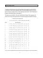
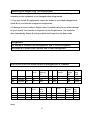
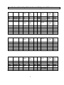
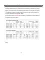
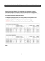
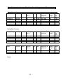
Entrée LLC
Refrigeration Products Service Manual
Entree
Freezer & Refrigerators
Installation, Specifications, Service, Electrical Diagrams, Service
Troubleshooting Guidelines, Warranty Guidelines
Table of Content
Section
Page Numbers
Electrical Requirements-----------------------------------------3
Wire Sizing Chart------------------------------------------------4
Serial Number Information-------------------------------------5
Receiving & Inspection-----------------------------------------6
Equipment Specifications---------------------------------------6 thru 11
Installation of Refrigeration Equipment-----------------------12 thru 13
Equipment Operating Temperatures---------------------------13
Defrost Section--------------------------------------------------14 thru 20
Temperature Controllers----------------------------------------21 thru 25
Sequence of Operation -----------------------------------------25
Compressor Section---------------------------------------------26 thru 31
Refrigeration Section--------------------------------------------32 thru 36
Information About Polyol Ester Oil-----------------------------37
Doors & Hardware-----------------------------------------------38 thru 42
Wiring Diagrams-------------------------------------------------43 thru 66
Warranty Guidelines ---------------------------------------------67 thru 70
Maintenance and Care -------------------------------------------71 thru 73
Lamp Replacement on Merchandiser----------------------------74
2
Electrical Requirements
There are several electrical factors that can affect the operation
of an Entrée Refrigerator or Freezer. Listed below are items that
need to checked prior to installation of your refrigeration
equipment? If not checked prior to installation can cause
needless service calls and voided warranty.
Entrée only uses two types of electrical plugs on their
equipment. Your outlets should match
NEMA 5-15R Used on units except the 3 Door Freezers
NEMA 5-20R Used on All 3 Door Freezers
1-Make sure circuit is a dedicated circuit exclusively for that
equipment.
2- No Extension Cords, Use of an extension cord WILL VOID
WARRANTY
3-All electrical complies with city electrical codes
4- Check for proper voltage at receptacle prior to plugging in
equipment.
5- Voltage drops must not exceed more than 10% on
compressor start up.
6-Alteration to electrical plug or cord WILL VOID WARRANTY
3
Wire Sizing Chart
To prevent voltage drops in the electrical power being supplied to a given Entrée
unit, below is a wire size to amperage chart. To prevent voltage drops of no more
than 2% wire size, length of wire run by amperage must match. Volts & Amperage is
located on the label location shown page 3
This chart is for only 105 to 120 volts, as all Entrée & Centaur Plus equipment are
based on 115 volts. The highest load on any Entrée Equipment would be 20 amps
Distance in feet to Center Load
20’
30’ 40’ 50’ 60’ 70’ 80’ 90’ 100’ 120’ 140’ 160’
Amps
Wire Gauge Size
2
14
14
14
14
14
14 14
14
14
14
14
14
3
14
14
14
14
14
14 14
14
14
14
14
12
4
14
14
14
14
14
14 14
14
14
12
12
12
5
14
14
14
14
14
14 14
12
12
12
10
10
6
14
14
14
14
14
14 12
12
12
10
10
10
7
14
14
14
14
14
12 12
12
10
10
10
8
8
14
14
14
14
12
12 12
10
10
10
8
8
9
14
14
14
12
12
12 10
10
10
8
8
8
10
14
14
14
12
12
10 10
10
10
8
8
8
12
14
14
12
12
10
10 10
8
8
8
8
6
14
14
14
12
10 10
10
8
8
8
6
6
6
16
14
12
12
10 10
8
8
8
8
6
6
6
18
14
12
10
10
8
8
8
8
6
6
6
5
20
14
12
10
10
8
8
8
6
6
6
5
5
Warning: Any compressor failing to start due to wire size for length of run, will not be warrantied
4
Serial Number Information:
The Model & Serial numbers and other information label are located on the left
interior wall at eye level.
You will need this information when placing a warranty service call or for warranty
parts
Serial Numbers: The first 2 numbers are the year the second 2 numbers are the month
1301ENTH00000 = year 2013 Month January
For Warranty Service:
Entrée Call------------------- 866-417-6140
Centaur Plus Call------------ 866-392-0792
For Tech Support Call------- 570-752-4602
To Purchase Parts Call------ 800-877-2662
5
Receiving & Inspecting The Equipment
Even though most equipment is shipped crated, care should be taken during
unloading so the equipment is not damaged when being moved.
1: Once you uncrate the equipment, inspect for hidden or concealed damages both
inside & out, and also the compressor compartment.
2: If damage is found, notify to freight carrier. If possible take pictures of the damage
for your records. And request an inspection by the freight carrier. This should be
done immediately. Retain all crating material until inspection has been made.
Refrigerants
All Entrée & Centaur Plus Refrigerators use R-134A Refrigerant
All Entrée & Centaur Plus Freezers use R-404A Refrigerant
SPECIFICATIONS For Entrée Reach-In Refrigerators & Freezers
Model
V/Hz/PH
Amps
Capacity
Cu-Ft’
CR1
CR2
CR3
115/60/1
115/60/1
115/60/1
6
9
10
23
49
72
Model
V/Hz/PH
Amps
Capacity
Cu-Ft
CF1
CF2
CF3
115/60/1
115/60/1
115/60/1
9
12
17
23
49
72
Capacity
Shelf Sq.
Ft.
14.0
28.1
42.1
Capacity
Shelf
Sq.-Ft.
14.0
28.1
42.1
Note:
6
HP
BTU
Refrigerant
Charge
3/8
½
¾
3200
5800
7625
12 R-134A
18.7 R-134A
21.2 R134A
HP
BTU
Refrigerant
Charge
5/8
1
2325
3650
4500
15.2 R-404A
1-1/4
26.6 R-404A
28.2 R-404A
Shipping
weight
LBS
350
518
669
Shipping
Weight
LBS
364
568
776
NEMA
Plug
Type
5-15P
5-15P
5-15P
NEMA
Plug
Type
5-15P
5-15P
5-20P
Specifications Entrée Prep & Under Counter Refrigerator & Freezers
Model
V/Hz/PH
Amps
Capacity
CU-Ft
P47
P70
P94
Model
115/60/1
115/60/1
115/60/1
V/Hz/PH
7.5
7.5
9
Amps
12
22
32
Capacity
CU-Ft
S29
S48
S61
S29-MT
S48-MT
S61-MT
115/60/1
115/60/1
115/60/1
115/60/1
115/60/1
115/60/1
5
7
7
5
7
7
7
12
15.5
7
12
15.5
Model
V/Hz/PH
Amps
Capacity
CU-Ft
UR27
UR48
UR61
WTR27
WTR48
WTR61
115/60/1
115/60/1
115/60/1
115/60/1
115/60/1
115/60/1
5
5
5
5
5
5
6.5
12
15.5
6.5
12
15.5
Model
V/Hz/PH
Amps
Capacity
CU-Ft
UF27
UF48
UF61
WTF27
WTF48
WTF61
115/60/1
115/60/1
115/60/1
115/60/1
115/60/1
115/60/1
7
9
10
7
9
10
6.5
12
15.5
6.5
12
15.5
Capacity
Shelf
Sq. Ft.
16
34
54
Capacity
Shelf
Sq. Ft.
14
26
30
14
26
30
HP
BTU
Refrigerant
Charge
½
½
¾
HP
5600
6200
6800
BTU
9.9 R-134A
3/8
½
1/2
3/8
½
½
3200
5400
5800
3200
5400
5800
9.5 R-134A
Capacity
Shelf
Sq. Ft.
14
26
30
14
26
30
HP
BTU
Refrigerant
Charge
3/8
3/8
3/8
3/8
3/8
3/8
2800
3000
3200
2800
3000
3200
9.5 R-134A
Capacity
Shelf
Sq. Ft.
14
26
30
14
26
30
HP
BTU
Refrigerant
Charge
1/2
1/2
5/8
1/2
1/2
5/8
3500
3800
4200
3500
3800
4200
12.3 R-4-04A
Note:
7
10.6 R-134A
13.8 R-134A
Refrigerant
Charge
9.5 R-134A
10.6 R-134A
9.5 R-134A
9.5 R-134A
10.6 R-134A
9.5 R-134A
10.6 R-134A
9.5 R-134A
9.5 R-134A
10.6 R-134A
14.5 R-404A
15.2 R-404A
12.3 R-404A
14.5 R-4044A
15.2 R-4044A
Shipping
Weight
LBS
348
432
582
Shipping
Weight
LBS
276
313
362
276
313
362
NEMA
Plug
Type
5-15P
5-15P
5-15P
NEMA
Plug
Type
5-15P
5-15P
5-15P
5-15P
5-15P
5-15P
Shipping
Weight
LBS
243
300
348
243
300
348
NEMA
Plug
Type
5-15P
5-15P
5-15P
5-15P
5-15P
5-15P
Shipping
Weight
LBS
243
300
348
243
300
348
NEMA
Plug
Type
5-15P
5-15P
5-15P
5-15P
5-15P
5-15P
Specifications for Centaur Plus Reach-in Refrigerators & Freezers Top Mount
Top Mount Units Meaning: The condensing unit (compressor) is located on top of the
cabinet. The benefit to this is the condenser stays cleaner as it is not near floor traffic.
1-The drawback is the air is warmer closer to the top of a room and the customer is
not able to stack things on top of the cabinet.
2- Customer should be WARNED when purchasing a Top Mount unit that nothing can
be stacked on top of the cabinet.
Notes:
8
Specification for Centaur Plus Refrigerators & Freezers – Bottom Mount
Bottom Mount Units Meaning: The condensing unit (compressor) is located
underneath the cabinet. The benefit to this is the air intake for the condenser is
located near the floor where the intake air for the condenser is cooler. The condenser
coil is easier accessed for cleaning and service.
The drawback to Bottom Mount unit is the air intake to the condenser is more
susceptible to dirty & lint being drawn on to the condenser surface.
WARNING: All Condenser should be check and cleaned every 30 Days
Note:
9
Specifications for Centaur Plus Prep & Under Counter
Refrigerators & Freezers
Notes:
10
Specifications for Centaur Plus Glass Door Refrigerators & Freezers
Swing Door Refrigerators
Model
V/Hz/PH
AMPS
Capacity
CU.-FT.
HP
BTU
Refrigerant &
Charge OZ
Shipping
Weight
CGD-1DR-12
CGD-1DR-16
CGD-1DR-23
CGD-2DR-48
CGD-3DR-70
115/60/1
115/60/1
115/60/1
115/60/1
115/60/1
6
6
6
7
10
12
16
23
48
72
3/8
3/8
3/8
½
¾
2800
3000
3200
5800
7625
12 R-134A
12 R-134A
12 R-134A
18.7 R-134A
21.2 R-134A
254
282
331
540
741
NEMA
Plug
Type
5-15P
5-15P
5-15P
5-15P
5-15P
Swing Door Freezers
Model
V/Hz/PH
AMPS
Capacity
CU.-FT.
HP
BTU
Refrigerant &
Charge OZ
Shipping
Weight
CSD-1DF-12
CGD-1DF-16
CGD-1DF-23
CGD-2DF-48
CGD-3DF-70
115/60/1
115/60/1
115/60/1
115/60/1
115/60/1
11
11
11
12
16
12
16
23
48
72
3/8
5/8
5/8
1
1¼
2325
2800
3000
3650
4500
10.6 R-404A
11.3 R-404A
14.1 R-404A
25.0 R-404A
28.9 R-404A
258
289
353
567
829
NEMA
Plug
Type
5-15P
5-15P
5-15P
5-15P
5-20P
Model
V/Hz/PH
AMPS
Capacity
CU.-FT.
HP
BTU
Refrigerant &
Charge OZ
CGD-2DR-47
115/60/1
7
47
½
5800
18.7 R-134A
Shipping
Weight
LBS
540
NEMA
Plug
Type
5-15P
Notes:
11
Installation of all Refrigeration Products
Location:
Units represented in this manual are intended for indoor use only. Be sure the
location chosen has a floor strong enough to support the loaded weight of the
cabinet and its contents. A fully loaded cabinet can weight can be as high as 1500
pounds. Reinforce floor as necessary to provide for maximum weight. For the most
efficient operation of the refrigeration system be sure to provide good air circulation
inside and out. Check specification sheet for unloaded weights
Inside The Cabinet:
Do not pack the cabinet in such a way to prevent good air circulation. This is
important to provide good heat recovery from all the product and prevent freeze ups
or damage to the compressor. This will also cause overflow of evaporator drain pans
and loss of temperature. The shelves are wire type to allow good air circulation
through the product. DO NOT cover shelves with any type of covering such as
aluminum foil. Boxes or packages should be placed in such a way to allow air flow
through them. DO NOT stack package or boxes against the interior back wall, as this
will stop air flow or against the intake air inlet to the evaporator coil.
Outside The Cabinet:
Cabinet should have access to ample fresh air. ALL Cabinets should be at least 2
inches off any interior wall to prevent re-circulation of hot air into the condenser coil.
If the unit is not provided with proper air circulation to the condenser coil, an
increase in temperature will occur. This could also cause damage to the compressor
and refrigeration system.
Leveling:
A level cabinet looks better and will perform better because the doors will be aligned
properly. Improperly leveled cabinet can cause condensate water to overflow either
the evaporator or condensate drain pans.
Use a level to properly level you refrigeration unit, to ensure proper operation of the
cabinet.
12
Stabilizing:
All models are supplied with casters for your convenience, ease of cleaning
underneath and for mobility. It is very important, however, that the cabinet be
installed in a stable condition with the front wheels locked while in use. Should it
become necessary to lay the unit on its side or back for any reason, allow at least 24
hours before start-up so as to allow compressor oil to flow back to the sump. Failure
to meet these requirements can cause compressor failure and unit damage.
Laying a cabinet on its side or back can also cause the motor mounting springs inside
the compressor to come off. This will cause the compressor to make a banging sound
at start up or shut down.
Warning: Unit repairs will not be subject to standard unit
warranties due to improper installation procedures.
Warning: The unit should always be disconnected or unplugged
when performing any kind of service or maintenance.
Operating Temperatures:
Refrigerators
All Entrée products refrigerators have a set point setting of 34 degrees F, At 34
degree the compressor will cycle off. The refrigerator has a differential setting of 4
degrees F. The refrigerator will cycle the compressor back on when the temperature
rises to 38 degrees. This should maintain a product temperature of approximately 35
degrees continually.
Freezers
All Entrée products freezers have a set point setting of -7 degrees F. At -7 degrees the
compressor will cycle off. The freezer has a differential setting of 4 degrees F. The
freezer cycle the compressor back on when the temperature rises to -3 degrees. This
should a product temperature of approximately -5 degrees continually.
13
Defrost Section
Refrigerator
Defrost Frequency:
6 hours from the time power is first applied to the cabinet
the first defrost will occur and every 6 hours of continual use. If power is interrupted
by a short power outage this will cause the unit to restart its count and the unit will
go into defrost 6 hours after power is restored.
This could cause the unit to miss a defrost cycle, and could cause a freeze up of the
defrost coil. You can place the unit into a manual defrost by pressing the snow flake
to the left of the “set” button on the controller and hold down for 4 seconds.
Defrost Duration: Maximum of 20 minutes factory setting or when the
evaporator probe reaches a temperature of 41 degrees F. or whichever comes first.
Freezer
Defrost Frequency: Defrost Frequency:
6 hours from the time power is first
applied to the cabinet the first defrost will occur and every 6 hours of continual use. If
power is interrupted by a short power outage this will cause the unit to restart its
count and the unit will go into defrost 6 hours after power is restored.
This could cause the unit to miss a defrost cycle, and could cause a freeze up of the
defrost coil. You can place the unit into a manual defrost by pressing the snow flake
to the left of the “set” button on the controller and hold down for 4 seconds.
Defrost Duration: Maximum of 20 minutes factory setting or when the
evaporator probe reaches a temperature of 45 degrees F. or whichever comes first.
Defrost is controlled by the controller and can be changed by going into the
parameters. This is not recommended, but can be change to fit the volume of the use
of the refrigerator or freezer. The number of times the door is opened is the volume
of the use.
NOTE: More about defrost is cover in the Controller Section
14
Drain Tube Heater
Note: All Entrée & Centaur Plus have drain tube heaters that operates only during
the defrost cycle. The drain tube heater part number H00211 is used on all freezers,
and it is 115v at 13 watts and approximately .007 Amps
Defrost Heater Amperage per Model
Note: None of the refrigerator models in either Entrée or Centaur Plus have defrosts
heaters. All refrigerators are off cycle defrost, the compressor is turned off a
maximum of 20 minutes.
All Entrée & Centaur Plus Freezers have electric defrost heaters, listed below is the
amperage for each model.
Entrée Reach-ins
Model
CF1
CF2
CF3
Volts and Watts
115 V at 550 watts
115 V at 800 watts
115 V at 1100 watts
Total Defrost Amps
4.85
7.03
9.63
Part number
H00201
H00202
H00203
Total Defrost Amps
2.98
4.09
4.10
Part Number
H01201
H01202
H02201
Total Defrost Amps
4.85
7.03
9.63
Part Number
H00201
H00202
H00203
Entrée Under Counters & Worktops
Model
UF27 & WTF27
UF48 & WTF48
UF61 & WTF61
Volts and Watts
115 V at 335 watts
115 V at 463 watts
115 V at 464 watts
Centaur Plus Bottom Mount Freezers
Model
CSD-1DF-BAL
CSD-2DF-BAL
CSD-3DF-BAL
Volts and Watts
115 V at 550 watts
115 V at 800 watts
115 V at 110 watts
15
Centaur Plus Top Mount Freezers
Model
CSD-1DF-TSI
CSD-2DF-TSI
CSD-3DF-TSI
Volts and Watts
115 V at 550 watts
115 V at 800 watts
115 V at 110 watts
Total Defrost Amps
4.85
7.03
9.63
Part Number
H00201
H00202
H00203
Total Defrost Amps
2.98
4.09
4.10
Part Number
H01201
H01202
H02201
Centaur Plus Undercounter & Worktop
Model
CUF27 & CWF27
CUF48 & CWF48
CUF61 & CWF61
Volts and Watts
115 V at 335 watts
115 V at 463 watts
115 V at 464 watts
Troubleshooting Defrost Related Problems:
How to Initiate a Manual Defrost: Push the snowflake to the left of the set button and
hold down for 4 seconds to activate a defrost cycle.
Note: A freezer temperature must be below 20 degrees F. for it
activate a defrost cycle. A refrigerator must be below 38
degrees F. to activate a defrost cycle.
After 4 seconds the compressor and interior fan motors should
shut off and the LED light under the snowflake with droplets
should light up.
16
Once unit is in defrost:
Step 1- If the unit is a 2 door or 3 door reach-in there will be a defrost contactor
located behind the shroud the controller is mounted on. To open shroud, remove
screws above the doors, the top of the shroud is hinged so the shroud can be swung
up to give you easy access to wiring & components.
Step 2- Identify the defrost contactor; it will be the contactor that is energized. If
neither contactor is energized, then go to the # 7 terminal on the controller, with a
volt meter check voltage to a neutral (white) wire.
A- No voltage, controller is bad replace it.
B- If you have voltage at #7, then check voltage at the defrost contactor coil, if you
have voltage to the coil, but the contactor is not energized the contactor coil is open,
replace the contactor.
C- If the contactor is energized check the terminals across the contactor, no
voltage reading the contactor is closed. If you get a voltage reading the contactor
terminals are open, replace the contactor.
D- If you determine the contactor is good, place an Amp Meter cross the terminal
or load side terminal. If you get an amp reading check one of the charts to match the
model number in defrost amp section of this book to determine if it correct.
E- No amp reading, then either you have an open defrost heater, an open thermal
cutoff or a loose connector.
F- Pictured below is the Thermal Cutoff, it should be bypassed to determined that
the defrost & drain tube heaters are both okay
G- If defrost heater and drain tube heater test okay, replace thermal cutoff
17
Defrost continued;
Note: The same procedure above will apply as a troubleshooting guide for the single
door reach-in and the Undercounter & Worktop Freezer. There is no defrost
contactor on the single door reach-in or the undercounter or worktop units. Defrost
circuit to defrost heaters comes directly off the #7 terminal of the controller.
Defrost Heater: Is located underneath the evaporator coil.
Step 3- Changing Defrost Settings
Note: Changing the defrost setting will not always cure the evaporator freeze up
problem. Be sure steps 1 & 2 have been accomplished prior to making any changes
in the defrost settings. They should only be changed when the unit is in a high
volume kitchen or high humidity area. If it is determined a change must be done to
the settings:
A- The controller controls all defrost settings.
18
Defrost Continued:
B- To get into the parameters see instructions on the picture above. Once “HY”
appears release both the down arrow & set buttons, then push and release” set” only
to go through the parameters.
C-The Defrost Parameters:
Parameter code
Description
dtE
idF
MdF
Defrost Termination Temp
Intervals between Defrost
Minutes of the Defrost
Default
Setting
45
6
20
Maximum Setting
52
4
30
Causes of Evaporator Freeze Ups for Freezer:
1- Thermal Cutoff open – Defrost Heaters will not operate in the defrost cycle if the
thermal cutoff is open.
2- Defrost Heater Open- Have voltage at the defrost heater wires, but no amp draw.
Determine with an Ohm meter if heater has an open circuit.
3- Failed Defrost Contactor- Either open coil or contacts
4- Failed Controller- open contactor at terminal #7 on controller
5-Failed Drain Tube Heater- This will cause the drain to freeze up stopping the flow of
condensate water during defrost cycle.
6-Clogged Drain- Trash or left over particles from manufacturing can clog drain
7-Poor air circulation inside the cabinet.
8- Door left ajar
9- Failed Evaporator Fan Motors- No air moving across the evaporator coil to gain
heat.
10- Bad door switch (only on the Centaur Plus Units) this will keep the evaporator fan
motors from operating.
11- Loose or burnt wire connectors12- Dirty evaporator coil- No air movement through the evaporator coil.
19
Defrost continued;
13-Evaporator Fan Blade loose or on backward
14- Bad Door Gaskets
Causes of Evaporator Freeze Ups for Refrigerators:
Note: Refrigerators do not use defrost heaters or contactors; they are strictly turn off
the compressor for up to 20 minutes.
1- Low Refrigerant Charge- If the unit cannot reach set point setting of 34 degrees F.
The P2 evaporator sensor will not allow the unit to go into a defrost cycle. The will
never reach the 34 degree set point. The unit runs continually until it freezes up.
2- Dirty condenser or poor air circulation around the condenser. The results will be as
described as in step 1.
3- Clogged drain
4-Failed controller: Will not go into manual defrost even with the temperature at 34
degrees.
5- Bad evaporator fan motor
6-Evaporator fan blade is loose or on backward.
7- On Sandwich / Salad or Pizza Prep units the condiment pans have to be in place on
the rails to keep warm air from entering the unit. If they are left out overnight or long
periods of time or don’t fit properly on the rails, this can also cause an evaporator
freeze up. Make sure all pans set completely down on the rail to make a good seal.
8- Bad Door Gaskets
9- The Controller’s set point is set to cold. Set point on refrigerators should never be
set below 33 degree F.
Notes:
20
Controllers
Note: Listed below are the specifications for the Dixell Controllers. Entrée only uses
the Dixell XR20C for Refrigerator units and the XR60C for the Freezer units.
Sometimes you may receive a Dixel XR02CX as a replacement for the refrigerators.
The parameters will be the same as the XR20C.
Set Point – Is the temperature the compressor will cycle off
Differential – Added to the Set Point is the temperature the compressor will cycle
back on.
Example: Refrigerator factory Set Point 34 degree F. plus 4 degree differential = 38
degree F
ALL REPLACEMENT CONTROLLERS ARE PRE-PROGRAMMED
AND A “HOT KEY” IS NOT NECESSARY.
Trouble Shooting Tips for Controller:
1- Do you have a temperature reading on the controller. If no then you have no
power to the controller. Check the power switch, power cord and breaker.
2- Controller has a temperature reading, but nothing is running. Are any of the LEDS
lite up.
21
a- Check set point setting, Freezers should be at -7 degrees and refrigerators at 34
degrees.
b- If set points are correct, check output voltage to fans & compressor. No output
voltage, replace controller.
Alarm Display:
P1 is flashing on the controller. This is an indication of failure in the thermostat
probe located near the intake air of the evaporator. To resolve this failure:
1- Inspect for a loose connection at the controller on terminal 11 or 12.
2- Inspect that it is wired properly as this happens often when replacing the
controller.
3- Inspect for cut or nicks in the probe wire.
4- If all the above check okay, replace probe
P2- is flashing on the controller. This is an indication of failure in the evaporator
probe located on the front side of the evaporator coil. To resolve this failure:
1- Inspect for a loose connection at the controller on terminal 10 or 11.
2- Inspect that it is wired properly as this happens often when replacing the
controller.
3- Inspect for cuts or nicks in the probe wire.
4- If all the above checks okay, replace probe
Both P1 & P2 are flashing on the controller. This will occur, but rarely.
1- Inspect all wire connections of 9, 10, 11& 12 terminals.
Note: The “11” terminal is the common terminal for all probes.
2- Best advise if you are getting an indication of failure on all probes
Replace the controller and probes
22
P3- is flashing on the controller. This is an indication of failure in the condenser
probe located on the compressor discharge line at the condenser coil. Use the same
steps as for P1-P2 probes, except the terminals will be 9 & 11. Note: The P3 probe is
not used on all units, only those with only one condenser fan motor.
CSd- is flashing on the controller. This is an indication of high compressor discharge
temperatures.
1- The condenser coil is clogged with trash or dirt. Clean
2- The condenser fan motor has failed. Replace
3- Bad air circulation, inspect the location of the unit and determine if it is getting the
proper air flow to the condenser coil. All cabinet should be at least 2” off any interior
wall. Units are not designed to operate in ambient temperature above
95
degrees F.
Controller Alarms continued:
HA – is flashing on the controller. This is an indication the unit has reached the high
temperature alarm setting, and has remained there for more than 90 minutes.
This could be caused by several conditions. Inspect the unit this may require putting
refrigeration gauges on the system.
LA- is flashing on the controller. This is an indication the unit has reached the low
temperature alarm setting, and remained there for more than 90 minutes.
This could be cause by several conditions, such as a bad controller or stuck contactor.
Warning: Prior to changing any parameters on the controller, you need to check
with Entrée Technical Support, by changing any setting can change the set up of the
engineering design.
23
Controller Terminals:
Refrigerator Controller Terminals
Freezer Controller Terminals
Location of Contactors and Terminal Boards
Located behind upper shroud
Notes:
24
Dixell Specification:
25
Compressor Troubleshooting Section
Quick Check Reference:
A) Compressor not operating:
1) Is the compressor extremely hot?
a) If the compressor is not operating and the condenser fans are operating,
Compressor is extreme hot, the compressor is off on the overload.
b) Is the condenser coil clean? You should be able to see light through the
condenser coil.
c) Compressor tries to start but trips overload.
1) What is the amp draw at the common terminal?
2) What is the startup voltage at the common & run compressor terminals.
3) Have you checked for burnt wire connection?
4) Have you tried a hard start kit, Start Cord or Compressor analyzer?
B) Compressor is cool to touch & not operating, condenser fan is operating
1) Have you checked voltage at the compressor terminals?
2) Have you taken Ohm readings across the terminals?
3) Checked for burnt or loose connections?
C) Neither compressor or condenser fan motor operated. Compressor is cool to
touch.
1) Checked voltage at the compressor contactor coil?
Continued on the next page
26
Compressor Trouble shooting continued
Contactor & Terminal locate behind shroud in right hand picture
Compressor Contactor
Upper shroud is hinged
a) Is the controller giving a digital reading? Is the snow flake lite up at the top
of the temperature readings?
b) If no power go to back of the controller and check power on the
compressor terminal. Terminal # 5 for refrigerators and terminal #3 for freezers
c) Checked voltage at the terminal board terminals that feed power to the
condensing unit.
Compressor Troubleshooting continued:
d) Loose wire or connector
D) Compressor Operating, but no cooling
a) Is the condenser clean?
b) Is the compressor discharge line hot or cool?
c) Is the there any heat on condenser coil?
d) Is the drier or cap tube sweating?
e) Is the evaporator coil iced up?
27
Embraco Aspera Compressors for Entrée & Centaur Plus
Typical Compressor wiring diagrams
For the models of Embraco/Aspera compressor used for Entrée / Centaur Plus
28
Compressors continued:
The Potential Start Relay:
The potential (voltage sensing) start relay places the starting capacitor in series with
the start windings. It does so by sensing voltage across the start winding, rather than
line current as does the current relay.
The contacts of the potential relay are normally closed and the start capacitor is
connected to the start winding as soon as power is applied to the compressor motor.
The relay’s coil senses the voltage dropped across the start winding. It is designed to
pick up, open its contacts, and disconnect the start capacitor from the start winding,
WHEN SUFFICIENT VOLTAGE IS GENERATED. Since the voltage or back-EMF
generated by the start winding is proportional to the motor speed, the relay will open
only when the motor has started and is approaching normal running speed.
EMF= Electromotive Force
This is why it is very important to have units with larger compressor such
as 3 door freezers being supplied with sufficient voltage and no voltage
drops at the compressor terminals. Any voltage drop at the compressor
of more than 10% will cause continual circuit breaker trips.
The Current Relay
Current Starting Relays are used on the smaller compressor motors. The current relay
contacts are normal open when de-energized, unlike the potential relay with closed
contacts. Current relay its coil is wound with heavy wire and is placed in series with
the incoming power line. The connections to the current relay are L, M, and S
alternate connections are 1, 5, and 2. When the compressor is energized in –rush
currents pass through the current relay coil, its contacts close and connect the start
winding to the motor circuit. The start winding is wound with a higher resistance than
the run winding, this changes its phase current with respect to the run windings, and
produces the torque requires for the motor to start. The relays contacts open when
current drops as the compressor comes up to speed, and the start windings is
disconnected from the motor circuit.
A current or potential relays can be tested with an Ohm meter for open or closed
contacts or open coils.
29
Compressors continued
Most Common Compressor Failures:
Locked Up or Seized Motors: What is the Locked Rotor Amps (LRA), check
nameplate LRA to see if they match. This can only be tested with an Amp meter on
the Common or Run terminals. Cause is normally by loss of good lubricating oils,
liquid refrigerant flood back or high discharge temperatures. Refrigerant oils, high
discharge temperatures and flood back are covered in the refrigeration section.
Open Windings: This can only be tested with a good Ohm meter.
Causes of open windings are normally caused by spot burns in either the start or run
windings and the breakdown of the motor insulation.
Shorts to Ground: Can be tested with a good Ohm meter, by checking each
terminal to the compressor case or copper lines attached to the compressor.
Listed below is the most common cause of open windings or burnt compressors
1- Mis-wired
2- Solid contaminants in the refrigeration system
3- High acid in the refrigeration, due to previously poor clean ups of the refrigeration
system.
4-Operating out of specification
5- Loss of lubrication
6- Flood backs causing liquid refrigerant to be in crankcase
7-High discharge temperatures and inadequate sub-cooling for the compressor
motor
8-Short cycling
9- Failed starting components
30
Compressors continued;
Inefficient or Non pumping Compressor : Can only be determine with
the installation of refrigerant gauges on both the high side and low side of the
system. This cannot be determined by Amperage.
Determining if a compressor is inefficient, normally with both gauges on the system,
the system is operating at low head pressure, high suction and low amperage.
Sometimes when the compressor is turned off the suction line will get hot quickly.
Most common cause:
1- Poor maintenance: Condenser coil is dirty or clogged, condensers coils should be
cleaned at every 60 days.
2- Liquid Refrigerant Flood Back: Evaporator freezes ups is one of the most common
cause of liquid flood back, due to no heat gain to boil off refrigerant. Over charging
with refrigerant is a very common failure with a capillary system, all refrigerant
charges should be weighted in to the factory name plate spec. Refrigerator or freezer
doors are open for long periods, keeping the evaporator fan motors from operating.
Internal Noise:
Compressors are not designed to be laid on their side or turned
upside down. A hermetic compressor has internal mounting springs, which can come
off the mountings when this occurs. When this occurs the compressor will make a
banging sound at start up or shut down.
Liquid refrigerant is the other thing that can cause a compressor to be noisy.
A well trained refrigeration technician should take time to
investigate the cause of compressor failures. Often this is not
done, causing repeated callbacks they expect the customer or
manufacture to pay. Make it right the first time.
Notes:
31
Refrigeration Section
All of the Entrée & Centaur Plus Refrigeration Systems are capillary type systems, as
in the refrigeration diagram below.
THE CAPILLARY TUBE REFRIGERATION SYSTEM
Basics how a capillary system operates:
Starting at the motor compressor the refrigerant from a low pressure gas is compressed to a high
pressure gas and pumped into the condenser. In the condenser with the condenser fan motor
circulating air over the refrigerant inside the condenser coil, the refrigerant is condensed from a high
pressure gas to a high pressure liquid. The high pressure liquid then leaves the condenser and enters
the drier, which is designed to remove moisture & contaminants that maybe in the system. Liquid
refrigerant enters the capillary tube, the pressure is reduced as it enters the evaporator coil, the liquid
refrigerant starts to boil as heat is picked up in the evaporator and the refrigerant changes to a low
pressure gas. The low pressure gas enters the accumulator to boil off any liquid refrigerant prior to
returning to the compressor through the suction line.
32
Refrigeration continued:
The Capillary Tube:
The capillary tube is probably the simplest of all metering devises. The capillary tube
is commonly used as a metering devise used on self-contained refrigerators and
freezers. It is constructed of a single tube with inside diameter in the range of .026 to
.090 inches. It is between the drier & the evaporator coil, and a large portion of it
maybe coiled either at the evaporator or in the condensing unit section. See picture
to the below, most generally the capillary tube is either soldered or foil taped to the
suction line to create a heat exchanger. The size of the cap tube and the length are
carefully selected to match the pumping capacity of the compressor, saturation of the
evaporator and sub-cooling to the compressor motor
Advantages of a capillary tube system are no mechanical parts to fail and the
pressure equalize quickly after the compressor shut down.
Disadvantages of a capillary system are they can become plugged due the size of the
inside diameter. The evaporator can be filled with liquid when the compressor is shut
down. Some manufactures install liquid line solenoids in the liquid line to prevent this
from occurring.
With today’s refrigerants & polyester oils being used with capillary tubes it is very
important not to operate a system with high discharge temperatures above 250
degrees, as POE oil start to become gummy at approximately 275 degrees. This will
cause the drier to get plugged and a breakdown of the desiccant beads. If you inspect
a restricted capillary lined with WHITE POWDER inside, this has occurred.
33
Refrigeration continued:
Causes of High Discharge Temperature:
High discharge temperature is when the temperature at the discharge valve inside the
reach temperature high enough to do damage to the system.
1- Dirty or clogged condenser coil is the most common, poor maintenance by the
owner of the equipment.
2- System operating with no or low refrigerant charge, this will cause the overheating
of the compressor motor by no sub-cooling at the compressor.
3-Restricted capillary tube or kinked suction line will cause the same results as
previous note in low refrigerant.
Testing: Remember a refrigeration system has 2 sides. When testing for restriction
or low refrigerant charge, always install both the refrigerant high side & low side
gauges. You can add 4 ounces of refrigerant to the system to check if both pressures
increase. If the unit has some refrigerant in the system, cover up the front of the
condenser coil, as the high side pressure starts to increase the low side pressure
should also start to increase, if the unit is low of charge. If the unit is restricted, you’ll
not see an increase in pressure from the low side, and only a slight increase on the
high side. A sweating drier or capillary tube is good indication of a restriction.
Testing for Leaks: Once you have determined the unit is low of refrigerant. The
unit definitely has a refrigrant leak, systems are not shipped out low of refrigerant.
You can add a blend of nitrogen & refrigerant to the system, and increase the
pressure up to 175 PSI. Pressure above 175 can do damage to the system. Using a
(sniffer type) leak detector go over the system thoroughly. None of the Entrée
products line sets are inside the foamed walls and all are accessible. But remember
the foam will set off a leak detector. Once a leak is located and repaired (if repairable)
replace the drier, vacuum to 200 microns, test to see if vacuum holds, recharge the
system to the factory specs.
The drier capacity is equal to 032 drier.
34
Refrigeration continued
Warning: Do not install only low side gauges and start adding refrigerant to the
system, as this can do damage to the compressor. And never add liquid refrigerant to
the low side, this will damage the low side reed valves in the compressor. Always use
good refrigeration practices.
4- Oil Logged Evaporators: This is something that rarely happens on small systems. If
you do encounter this failure, place the system into a prolonged defrost, or heat the
evaporator up with a hot air gun. This will warm the refrigerant oil to increase the
viscosity of the oil and allow it to return once the compressor starts up. If this fails to
remedy the problem, then the evaporator and accumulator will have to be removed
and drained of the oil and then purged with nitrogen. Remember to fill a cup with the
drained oil and add that amount back into the compressor.
Good Refrigeration Practices:
Being a good refrigeration technician is being a good investigator. We in technical
support may ask you many questions. We are not questioning your abilities as tech,
but investigating to find a remedy to the problem. We in tech support are only as
good as the technician on the end of the phone line.
A good technician will find the cause of the problem, and remedy the problem to
eliminate it from happening again.
Before going into any refrigeration system, remember that POE oil is very
hydroscopic and absorbs moisture. Never leave a system open to the atmosphere for
more than 15 minutes. Always make sure you have every tool, etc. required to do the
job prior to opening a system. Prior to going into a system a technician can tell a lot
by feel. Feeling of the side of the condenser can tell if any heat is present and starting
at the top and running your hand top to bottom will tell you if you are condensing
refrigerant or moving refrigerant. Feeling of the suction line at the compressor will
tell the tech if there is sub-cooling at the compressor or if ice is present. If ice is
present at the suction line at the compressor, you are not gaining heat from the
evaporator coil. Look at your drier and capillary tube in the condensing section, is
there sweating present. These are simple test prior to tapping into a system. Tapping
into a system is the last thing a tech should do. Entrée will not kill a warranty if you
tap into a system after all these things have been tested.
35
Refrigeration continued
If you tap into a system, always tap into both the high & low sides. There are ¼”
processing tubes on both sides. Never call tech support to ask for refrigeration help
without having both readings, as we cannot help. We’ll only ask you to go back to get
both.
Once you have tapped into the refrigeration system. For testing purposes refer back
to testing earlier in this refrigeration section.
Replacing Refrigeration Components:
Never heat up or unsolder a drier when removing it from the system, this
releases contaminates into the system. Cut it out with tubing cutters.
Inspect the drier for gummy oil buildup or broken down desiccant beads.
Prior to installing a new refrigeration component into a system, it is our
recommendation the system is flushed, either by nitrogen a designated flush.
If the system has a burn out on the compressor windings, an acid test is good means
to test the refrigerant oil. Acid in the system is a compressor failure waiting to
happen. You can acquire an acid test kit from any local refrigeration supply.
A clean refrigeration system is system that will work properly with no return calls.
Notes:
36
Polyol Ester Oil:
After 20 years of using this lubricant in the refrigeration system, it has not improved.
HFC refrigerants require the use of POE oil for all Entrée compressors. This is
necessary for two specific reasons. First, mineral oils are not readily miscible in HFCs.
When using HFCs mineral oils will not return to the compressor. Secondly, the
chlorine contained in CFCs and HCFCs aids in the lubricity of the mineral oil.
POE oil has its drawbacks, first it is hydroscopic, moisture rapidly builds in this oil
when left to the atmosphere. Fifteen minutes is the longest any system should be left
open. Once moisture is mixed with the POE oil it is impossible to remove. Drain the
compressor crankcase, flush the system and install a new drier. Even this may not be
enough. Second, POE oil breaks down at high discharge temperatures, causing it to
become gummy. This will cause restrictions in the drier and metering devise. Once
this occurs it is almost impossible to remove. Again drain the compressor crankcase
by pouring it into a measuring cup, add fresh oil to the crankcase. Flush the system
with a good flush that is purchased from your local refrigeration supply. Replace the
drier. Cleaning up a system is very important when using POE oils. It is not as
forgiving as mineral oils.
Notes:
37
Doors & Hardware
Casters:
There are only two size of casters used on Entrée refrigeration products. All casters
are of the platform type. Below is the bolt holes pattern, at 2 3/8” centers.
a- The H01316 is used on all the salad/sandwich and under counter units. This is a
2.5 inch wheel, which will increase the cabinet height approximately 3.5 inches
b- The H00316 is used on all reach-in and pizza prep units. This is a 4” wheel, which
will increase the cabinet height approximately 5.5 inches.
Entrée does not at this time provide caster shims to level the cabinet.
Legs are not available for any of the Entrée or Centaur Plus units at this time.
Notes:
38
Door Gasket Replacement
There should be no tools required to replace a door gasket on any of the Entrée or
Centaur Plus Refrigeration units.
The door gaskets backside has a dart with a barbed end. The dart inserts into a plastic
groove on the inside of the door. The barbed end holds the gasket in place.
To remove the old gasket is very simple as show in the picture below. Garb the old
gasket and pullout until enough of the gasket is out to place your hand under it, you
can pull out the reminder of the old gasket.
Installing the new gasket by start in the upper corner and pressing the dart into the
groove on the inside of the door, then across the top, down each side and across the
bottom.
Note: Some gaskets have been rolled up for storage in the parts bins. They maybe
twisted and difficult to work with. These storage memories in the rubber gasket can
be taken out by place the gaskets in hot water for a few minute. Once the new gasket
has been installed, check to make sure it is sealing good against the cabinet. If an
area is not sealing good, warm that area up with a hair dryer and light pull out on the
gasket at the same time, this will allow the magnet then to seal against the cabinet.
Once the gasket has been installed a few days, re-check that no frost or sweating is
on the inside of the door or face of the cabinet. No frost or sweating means you have
a good seal.
39
Doors and Hardware continued:
Pictured (picture 1) below on the left is part of the hinge assemblies mounted to the
door. Both inserted into a square openings in the top and bottom of the door.
The longer of the two is called the hinge cartridge. The hinge cartridge has the spring
inside which makes the door self-closing. When replacing this component always
preload the spring by place a wrench on the square stub and turning it the direction
the door closes until resistance from the spring is met. This will ensure the door to
work properly after it is back on the cabinet.
The other part is the carrier for the Axis Hinge Pin. It is mounted to either the top or
bottom of the door depending on the application.
Pictured ( picture 2) below on the right is a picture of the Axis Hinge Pin bracket new
style, which is used on most all of the Entrée and Centaur Plus units.
Picture 1
Picture 2
Note: Door replacement parts are available for all Entrée,
Centaur Plus and Centaur Plus Glass Door Merchandisers.
40
Doors and Hardware continued:
Pictured (picture 3) below is the old style Axis Hinge Pin, this was used on Entrée
units only prior to 2010. These can still be ordered under part number H00327A. The
new style are pictured in picture number 2 on the previous page.
Picture 3
When replacing these old style Axis hinge pins, always use liquid lock tight on the
threads to keep the nut from backing off.
Note: You cannot replace the old style hinge pin (H00327A) with the new style
H00327).
Centaur Plus Doors
There is no replacement handle available at this time, the entire door must be
replaced.
41
Glass Door Replacement & Adjustments
Centaur Plus Glass Doors, there no replacement glass insert available door will need
to be replaced.
Swing Door Replacement and Adjustment
1. Open the bottom shroud and support the door weight. Loosen bottom hinge’s screws and
remove the door
2. Prepare new door. Insert door top pin into top hinge. Insert the bottom hinge onto the door’s
bottom hinge and secure to the frame
3. Allow the door to freely swing, make sure it swings close by itself with no restriction
4. Plug the unit in and make sure the lock is in the right location. Exercise the lock to ensure the
cam engagement
5. If not, adjust the door until proper lock cam engagement
Slide Door Replacement and Adjustment
1. Remove the hook of counterweight on the top of the door
2. Lift the door up until its bottom edge over the channel. Slide it out and down away from the
cabinet.
3. Reverse the procedures to install new door
Remove the shroud
1. Open the door/s.
2. Loosen and remove the top screws
3. Slide the shroud up and out of their keyhole shape slots
Light Bulb Replacement
1. Top display light bulb replacement: Loose the screws in the bottom of top shroud, swing the
top shroud
up until it is hold by the top of the cabinet, now light bulb can be replaced;
2. Interior light bulb replacement: Open door and remove the cover. Twist and remove the bulb.
42
Wiring Diagrams
Reach-in Refrigerator; CR1, CR2, CR3
43
Freezers Wiring Diagrams; CF1, CF2, CF3
44
Salad/Sandwich, Pizza Prep, Undercounters, Worktop
45
Undercounter, Worktop Freezers
46
Wiring Diagrams
Centaur Plus Bottom Mount One Door Refrigerators
47
Bottom Mount Two Door Refrigerator
48
Bottom Mount Three Door Refrigerator
49
Bottom Mount One Door Freezer
50
Bottom Mount Two Door Freezer
51
Bottom Mount Three Door Freezer
52
Top Mount One Door Refrigerator
53
Top Mount Two Door Refrigerator
54
Top Mount Three Door Refrigerator
55
Top Mount One Door Freezer
56
Top Mount Two Freezer
57
Top Mount Three Door Freezer
58
Salad/Sandwich, Undercounters,
Pizza Prep & Worktop Refrigerators
59
Undercounter & Worktop Freezers
60
Glass Door Merchandisers Single Door Refrigerator
MODEL: CGD-1DR-12/CGD-1DR-16/CGD-1DR-23
61
Glass Door Merchandiser Two Door Refrigerator
MODEL: CGD-2DR-48/CGD-2DR-47
62
Glass Door Merchandiser Three Door
MODEL: CGD-3DR-70
63
Glass Door Merchandisers Freezers
MODEL: CGD-1DF-12/CGD-1DF-16/CGD-1DF-23
64
Glass Door Merchandiser Two Door Freezer
MODEL: CGD-2DF-48
65
Glass Door Merchandiser Three Door Freezer
MODEL: CGD-3DF-70
66
Warranty Section
Warranty Allowances for all Entrée Refrigeration Products
Including Entrée, Centaur Plus®, CCK, Better Build.
All warranty claim invoices must include the following information for the invoice to be
processed. If this information is not included on the invoice, it will be denied and returned with
a letter of explanation.
A.
B.
C.
D.
E.
F.
G.
H.
Serial Number
Model Number
End User (Customer) business name, location and phone number.
Invoice must be signed by the customer or a person in their employment.
The National Service Coop Service Request number.
All invoices that are determined not to be a manufacturing defect will be denied.
All invoices that are not readable will be returned with a denial letter.
All invoices out of the guidelines of these allowances will be adjusted to the allowance,
unless prior approval and accompanied by authorized number from the Entrée Technical
Service Department.
Entrée does not pay for Helper charges or Trainee charges. All work can be performed by
one technician. Any Helper charges will have to be prior approved by Entrée Technical
Service Department. Entrée Technical Support 1-704-464-3008 ext. 2
End Users (Customers) Responsibilities:
A. To verify through NSC the unit is under warranty. A Bill of Sale may be required.
B. Pay for normal maintenance and adjustment. Entrée does not pay for adjustments, unless
prior approved.
C. To reimburse the service company for all non-warranty issues at the rates, travel time, etc.
set by the service company. Failure to do so could result in a void warranty.
D. Entree does not pay overtime or holiday charges, additional travel charges not covered by
warranty, equipment or tool charges not covered by warranty allowances.
Entrée is not responsible for the loss of any product or economic loss as a result
of failure of this product, caused by either, poor maintenance, acts of nature or
defects.
67
Payment for Warranty Travel:
A $100.00 charge for the first trip and $85.00 for the second trip with approval.
A $120.00 charge for the first trip and $100.00 for the second trip with approval for the
following high traffic areas within the metro areas.
Atlanta, Boston, Chicago, Dallas-Ft. Worth, Ft. Lauderdale, Houston, Los Angeles, Miami, New
York City, Philadelphia, San Diego, San Francisco or any area that would be considered a metro
area.
Warranty Parts Orders & Shipping Charges:
All warranty parts sent out by Entrée parts department are shipped UPS ground at no charge
to the Customer or the Service Company. All warranty parts that the customer request for Next
Day Delivery will be paid for by the Customer. The Service Company will be required to secure
payment of these charges from the Customer, and arrange for payment to Entrée for these
shipping charges.
Entrée will send a replacement part at no charge for commonly used parts that are held in
inventory by the Service Company and are used to repair a unit.
For non-inventory parts, we will ship at no charge. If we do not have the part in stock and it can
be acquired locally, Entrée will pay for the purchase cost of the part and $45.00 travel fee to
acquire the part. A copy of the invoice for the part must be submitted with the warranty claim.
Warranty Parts Return:
Entrée does not require at this time warranty defective parts to be returned. Entrée does not
pay any handling fees for parts return. If a warranty part is required to be returned, Entrée
Technical Department will notify the Service Company and pay shipping charges of all returned
parts.
Warranty Hourly Rates:
Please refer to the National Service Coop Rate Structure.
Labor Allowances for Reach-in Freezers, Refrigerators, Sandwich/Salad, Pizza
Tables, Work Tops, Under Counter Units.
Any labor hours out of these guidelines without prior approval by Entrée will be
adjusted to the guidelines. These time guidelines are based on the national
average of other manufactures of the same type of equipment.
68
Refrigeration System:
A. Diagnose and replace a defective compressor. This includes the starting components, drier,
recovery, welding, vacuum and recharge & test system…………………………………… 4.5 Hours
B. Diagnose and replace a defective evaporator coil. This includes drier, welding, recovery,
vacuum, recharge & test…………………………………………………………………………………… 5 Hours
C. Diagnose and replace a defective condenser coil. This includes drier, welding, recovery,
vacuum, recharge & test……………………………………………………………………………………..4 Hours
D. Diagnose and replace a defective or restricted capillary tube. This includes drier, welding,
recovery, vacuum, recharge & test……………………………………………………………………..5 Hours
E. Diagnose and locate a refrigerant leak. Leak location must be entered on the service
invoice. Entrée does not install Schrader or tap valves on its systems. Any leak located on
these components WILL NOT be considered a defect, but a call back on the service
company……………………………………………………………………………………………………………..4 Hours
F. All other defective refrigeration components. This includes drier, welding, recovery,
vacuum, recharge & test……………………………………………………………………………………..4 Hours
Cabinet:
A.
B.
C.
D.
E.
F.
G.
Replace a defective door gasket…………………………………………………………………………...1 Hour
Replace a defective door…………………………………………………………………………………… 1.5 Hours
Replace a defective caster…………………………………………………………………………………….1 Hour
Replace a bottom shroud………………………………………………………………………………………1 Hour
Replace a top shroud with controller mounted on it………………………………………….1.5 Hours
Replace a defective door hinge …………………………………………………………………………….2 Hours
Replace a defective door lock………………………………………………………………………………..1 Hour
Electrical Components:
A.
B.
C.
D.
E.
F.
G.
H.
I.
J.
K.
L.
Diagnose and replace compressor starting components………………………………………..3 Hours
Diagnose and replace a contactor………………………………………………………………………….2 Hours
Diagnose and locate an electrical short………………………………………………………………….3 Hours
Diagnose and replace a terminal board………………………………………………………………….2 Hours
Diagnose and replace a controller………………………………………………………………………….2 Hours
Diagnose and replace a controller with sensors……………………………………………………..3 Hours
Diagnose and replace a defrost heater …………………………………………………………………3.5 Hours
Diagnose and replace a drain line heater ……………………………………………………………..3.5 Hours
Diagnose and replace a thermal cutoff ………………………………………………………………… 3 Hours
Diagnose and replace a power switch ……………………………………………………………………2 Hours
Diagnose and replace a door (light & fan) switch ………………………………………………….2 Hours
Diagnose and replace a power cord……………………………………………………………………….2 Hours
69
Motors:
A. Diagnose and replace a condenser fan motor…………………………………………………………2 Hours
B. Diagnose and replace a evaporator fan motor ……………………………………………………1.5 Hours
C. Diagnose and replace a condenser or evaporator fan blade………………………………..1.5 Hours
Other Allowance:
Entrée will allow a $45.00 miscellaneous charge. This to include all of the following: recovery
unit, vacuum pump use, welding use, nitrogen, electrical test equipment, electrical fittings, rags
and cleaning supplies. All other will be adjusted out.
Entrée will pay a reasonable price for any tap valves, driers, etc. used in the repair of the
refrigeration system.
Refrigerant Allowance:
Entrée will pay the following price per ounce of refrigerant. We will also allow a few extra
ounces for leak testing, etc.
Refrigerant R-134a = $0.59 per ounce
Refrigerant R-404a =$0.83 per ounce
Any other refrigerant blends used other than those called for on the name plate of the unit will
VOID the warranty on that unit.
Multiple Repairs on the Same Unit:
A system that has more than one component failure. The service company can use the highest
time for the first component plus 1 hour for the additional component. Entrée will pay only one
trip charge for the first component.
Any items not covered by this warranty allowances you can call the:
Technical Support Department @ 704-464-3008 ext.2
70
Maintenance and Care
71
72
Drains and other Maintenance
Drain Maintenance
Each unit has a drain located inside the unit which removes the condensation from the
evaporator coil and evaporates it at an external condensate evaporator pan. Each drain can
become loose or disconnected from moving or bumping the drain. If you notice excessive water
accumulation on the inside of the unit, be sure the drain tube is connected from the evaporator
housing to the condensate evaporator drain pan. If water is collected underneath the unit you
may want to check the condensate evaporator drain tube to be sure it is still located inside the
drain pan. The leveling of the unit is important as the units are designed to drain properly when
on a level surface, if your floor is not level this can also cause drain problems. Be sure all drain
lines are free of obstructions typically food product is found blocking drain lines causing water to
back up and overflow the drain pans.
Salad/ Sandwich and Pizza Prep Condiment Pans
Pictured below is an example of how condiment pans should be used on a prep unit.
Condiment pans must be in place at all times, even if they are empty. Rails and divider
bars must be free of damage so the condiment pans will makes a good seal to prevent
warm air from entering the cabinet. Metal condiment pans should not be used as the
corners get damaged and allows warm air to enter into the cabinet. Damage rails or
dividers can cause the evaporator to freeze up. To maintain a trouble free unit take care
of the pans, rails and divider bars to make a good seal.
73
Replacing Lamps for Glass Door Merchandisers
1. Top display light bulb replacement: Loose the screws in the bottom of top shroud, swing
the top shroud up until it is hold by the top of the cabinet, now light bulb can be replaced;
2. Interior light bulb replacement: Open door and remove the cover. Twist and remove the
bulb.